EP3757960A1 - Server, monitor system, terminal, monitor device, and method, for monitoring oxygen concentration device - Google Patents
Server, monitor system, terminal, monitor device, and method, for monitoring oxygen concentration device Download PDFInfo
- Publication number
- EP3757960A1 EP3757960A1 EP19757466.8A EP19757466A EP3757960A1 EP 3757960 A1 EP3757960 A1 EP 3757960A1 EP 19757466 A EP19757466 A EP 19757466A EP 3757960 A1 EP3757960 A1 EP 3757960A1
- Authority
- EP
- European Patent Office
- Prior art keywords
- usage data
- oxygen concentrator
- oxygen
- operation data
- display
- Prior art date
- Legal status (The legal status is an assumption and is not a legal conclusion. Google has not performed a legal analysis and makes no representation as to the accuracy of the status listed.)
- Pending
Links
Images



Classifications
-
- G—PHYSICS
- G08—SIGNALLING
- G08B—SIGNALLING SYSTEMS, e.g. PERSONAL CALLING SYSTEMS; ORDER TELEGRAPHS; ALARM SYSTEMS
- G08B21/00—Alarms responsive to a single specified undesired or abnormal condition and not otherwise provided for
- G08B21/02—Alarms for ensuring the safety of persons
-
- G—PHYSICS
- G16—INFORMATION AND COMMUNICATION TECHNOLOGY [ICT] SPECIALLY ADAPTED FOR SPECIFIC APPLICATION FIELDS
- G16H—HEALTHCARE INFORMATICS, i.e. INFORMATION AND COMMUNICATION TECHNOLOGY [ICT] SPECIALLY ADAPTED FOR THE HANDLING OR PROCESSING OF MEDICAL OR HEALTHCARE DATA
- G16H40/00—ICT specially adapted for the management or administration of healthcare resources or facilities; ICT specially adapted for the management or operation of medical equipment or devices
- G16H40/60—ICT specially adapted for the management or administration of healthcare resources or facilities; ICT specially adapted for the management or operation of medical equipment or devices for the operation of medical equipment or devices
- G16H40/67—ICT specially adapted for the management or administration of healthcare resources or facilities; ICT specially adapted for the management or operation of medical equipment or devices for the operation of medical equipment or devices for remote operation
-
- A—HUMAN NECESSITIES
- A61—MEDICAL OR VETERINARY SCIENCE; HYGIENE
- A61B—DIAGNOSIS; SURGERY; IDENTIFICATION
- A61B5/00—Measuring for diagnostic purposes; Identification of persons
- A61B5/0002—Remote monitoring of patients using telemetry, e.g. transmission of vital signals via a communication network
- A61B5/0015—Remote monitoring of patients using telemetry, e.g. transmission of vital signals via a communication network characterised by features of the telemetry system
-
- A—HUMAN NECESSITIES
- A61—MEDICAL OR VETERINARY SCIENCE; HYGIENE
- A61B—DIAGNOSIS; SURGERY; IDENTIFICATION
- A61B5/00—Measuring for diagnostic purposes; Identification of persons
- A61B5/08—Measuring devices for evaluating the respiratory organs
-
- A—HUMAN NECESSITIES
- A61—MEDICAL OR VETERINARY SCIENCE; HYGIENE
- A61B—DIAGNOSIS; SURGERY; IDENTIFICATION
- A61B5/00—Measuring for diagnostic purposes; Identification of persons
- A61B5/08—Measuring devices for evaluating the respiratory organs
- A61B5/0816—Measuring devices for examining respiratory frequency
-
- A—HUMAN NECESSITIES
- A61—MEDICAL OR VETERINARY SCIENCE; HYGIENE
- A61B—DIAGNOSIS; SURGERY; IDENTIFICATION
- A61B5/00—Measuring for diagnostic purposes; Identification of persons
- A61B5/103—Measuring devices for testing the shape, pattern, colour, size or movement of the body or parts thereof, for diagnostic purposes
- A61B5/11—Measuring movement of the entire body or parts thereof, e.g. head or hand tremor or mobility of a limb
- A61B5/113—Measuring movement of the entire body or parts thereof, e.g. head or hand tremor or mobility of a limb occurring during breathing
-
- A—HUMAN NECESSITIES
- A61—MEDICAL OR VETERINARY SCIENCE; HYGIENE
- A61B—DIAGNOSIS; SURGERY; IDENTIFICATION
- A61B5/00—Measuring for diagnostic purposes; Identification of persons
- A61B5/145—Measuring characteristics of blood in vivo, e.g. gas concentration or pH-value ; Measuring characteristics of body fluids or tissues, e.g. interstitial fluid or cerebral tissue
- A61B5/1455—Measuring characteristics of blood in vivo, e.g. gas concentration or pH-value ; Measuring characteristics of body fluids or tissues, e.g. interstitial fluid or cerebral tissue using optical sensors, e.g. spectral photometrical oximeters
-
- A—HUMAN NECESSITIES
- A61—MEDICAL OR VETERINARY SCIENCE; HYGIENE
- A61B—DIAGNOSIS; SURGERY; IDENTIFICATION
- A61B5/00—Measuring for diagnostic purposes; Identification of persons
- A61B5/145—Measuring characteristics of blood in vivo, e.g. gas concentration or pH-value ; Measuring characteristics of body fluids or tissues, e.g. interstitial fluid or cerebral tissue
- A61B5/1455—Measuring characteristics of blood in vivo, e.g. gas concentration or pH-value ; Measuring characteristics of body fluids or tissues, e.g. interstitial fluid or cerebral tissue using optical sensors, e.g. spectral photometrical oximeters
- A61B5/14551—Measuring characteristics of blood in vivo, e.g. gas concentration or pH-value ; Measuring characteristics of body fluids or tissues, e.g. interstitial fluid or cerebral tissue using optical sensors, e.g. spectral photometrical oximeters for measuring blood gases
-
- A—HUMAN NECESSITIES
- A61—MEDICAL OR VETERINARY SCIENCE; HYGIENE
- A61M—DEVICES FOR INTRODUCING MEDIA INTO, OR ONTO, THE BODY; DEVICES FOR TRANSDUCING BODY MEDIA OR FOR TAKING MEDIA FROM THE BODY; DEVICES FOR PRODUCING OR ENDING SLEEP OR STUPOR
- A61M16/00—Devices for influencing the respiratory system of patients by gas treatment, e.g. ventilators; Tracheal tubes
- A61M16/0051—Devices for influencing the respiratory system of patients by gas treatment, e.g. ventilators; Tracheal tubes with alarm devices
-
- A—HUMAN NECESSITIES
- A61—MEDICAL OR VETERINARY SCIENCE; HYGIENE
- A61M—DEVICES FOR INTRODUCING MEDIA INTO, OR ONTO, THE BODY; DEVICES FOR TRANSDUCING BODY MEDIA OR FOR TAKING MEDIA FROM THE BODY; DEVICES FOR PRODUCING OR ENDING SLEEP OR STUPOR
- A61M16/00—Devices for influencing the respiratory system of patients by gas treatment, e.g. ventilators; Tracheal tubes
- A61M16/021—Devices for influencing the respiratory system of patients by gas treatment, e.g. ventilators; Tracheal tubes operated by electrical means
- A61M16/022—Control means therefor
-
- A—HUMAN NECESSITIES
- A61—MEDICAL OR VETERINARY SCIENCE; HYGIENE
- A61M—DEVICES FOR INTRODUCING MEDIA INTO, OR ONTO, THE BODY; DEVICES FOR TRANSDUCING BODY MEDIA OR FOR TAKING MEDIA FROM THE BODY; DEVICES FOR PRODUCING OR ENDING SLEEP OR STUPOR
- A61M16/00—Devices for influencing the respiratory system of patients by gas treatment, e.g. ventilators; Tracheal tubes
- A61M16/06—Respiratory or anaesthetic masks
- A61M16/0666—Nasal cannulas or tubing
- A61M16/0672—Nasal cannula assemblies for oxygen therapy
-
- A—HUMAN NECESSITIES
- A61—MEDICAL OR VETERINARY SCIENCE; HYGIENE
- A61M—DEVICES FOR INTRODUCING MEDIA INTO, OR ONTO, THE BODY; DEVICES FOR TRANSDUCING BODY MEDIA OR FOR TAKING MEDIA FROM THE BODY; DEVICES FOR PRODUCING OR ENDING SLEEP OR STUPOR
- A61M16/00—Devices for influencing the respiratory system of patients by gas treatment, e.g. ventilators; Tracheal tubes
- A61M16/10—Preparation of respiratory gases or vapours
- A61M16/1005—Preparation of respiratory gases or vapours with O2 features or with parameter measurement
- A61M16/101—Preparation of respiratory gases or vapours with O2 features or with parameter measurement using an oxygen concentrator
-
- G—PHYSICS
- G08—SIGNALLING
- G08B—SIGNALLING SYSTEMS, e.g. PERSONAL CALLING SYSTEMS; ORDER TELEGRAPHS; ALARM SYSTEMS
- G08B25/00—Alarm systems in which the location of the alarm condition is signalled to a central station, e.g. fire or police telegraphic systems
- G08B25/01—Alarm systems in which the location of the alarm condition is signalled to a central station, e.g. fire or police telegraphic systems characterised by the transmission medium
- G08B25/04—Alarm systems in which the location of the alarm condition is signalled to a central station, e.g. fire or police telegraphic systems characterised by the transmission medium using a single signalling line, e.g. in a closed loop
-
- G—PHYSICS
- G16—INFORMATION AND COMMUNICATION TECHNOLOGY [ICT] SPECIALLY ADAPTED FOR SPECIFIC APPLICATION FIELDS
- G16H—HEALTHCARE INFORMATICS, i.e. INFORMATION AND COMMUNICATION TECHNOLOGY [ICT] SPECIALLY ADAPTED FOR THE HANDLING OR PROCESSING OF MEDICAL OR HEALTHCARE DATA
- G16H20/00—ICT specially adapted for therapies or health-improving plans, e.g. for handling prescriptions, for steering therapy or for monitoring patient compliance
- G16H20/40—ICT specially adapted for therapies or health-improving plans, e.g. for handling prescriptions, for steering therapy or for monitoring patient compliance relating to mechanical, radiation or invasive therapies, e.g. surgery, laser therapy, dialysis or acupuncture
-
- G—PHYSICS
- G16—INFORMATION AND COMMUNICATION TECHNOLOGY [ICT] SPECIALLY ADAPTED FOR SPECIFIC APPLICATION FIELDS
- G16H—HEALTHCARE INFORMATICS, i.e. INFORMATION AND COMMUNICATION TECHNOLOGY [ICT] SPECIALLY ADAPTED FOR THE HANDLING OR PROCESSING OF MEDICAL OR HEALTHCARE DATA
- G16H40/00—ICT specially adapted for the management or administration of healthcare resources or facilities; ICT specially adapted for the management or operation of medical equipment or devices
- G16H40/40—ICT specially adapted for the management or administration of healthcare resources or facilities; ICT specially adapted for the management or operation of medical equipment or devices for the management of medical equipment or devices, e.g. scheduling maintenance or upgrades
-
- G—PHYSICS
- G16—INFORMATION AND COMMUNICATION TECHNOLOGY [ICT] SPECIALLY ADAPTED FOR SPECIFIC APPLICATION FIELDS
- G16H—HEALTHCARE INFORMATICS, i.e. INFORMATION AND COMMUNICATION TECHNOLOGY [ICT] SPECIALLY ADAPTED FOR THE HANDLING OR PROCESSING OF MEDICAL OR HEALTHCARE DATA
- G16H40/00—ICT specially adapted for the management or administration of healthcare resources or facilities; ICT specially adapted for the management or operation of medical equipment or devices
- G16H40/60—ICT specially adapted for the management or administration of healthcare resources or facilities; ICT specially adapted for the management or operation of medical equipment or devices for the operation of medical equipment or devices
-
- G—PHYSICS
- G16—INFORMATION AND COMMUNICATION TECHNOLOGY [ICT] SPECIALLY ADAPTED FOR SPECIFIC APPLICATION FIELDS
- G16H—HEALTHCARE INFORMATICS, i.e. INFORMATION AND COMMUNICATION TECHNOLOGY [ICT] SPECIALLY ADAPTED FOR THE HANDLING OR PROCESSING OF MEDICAL OR HEALTHCARE DATA
- G16H40/00—ICT specially adapted for the management or administration of healthcare resources or facilities; ICT specially adapted for the management or operation of medical equipment or devices
- G16H40/60—ICT specially adapted for the management or administration of healthcare resources or facilities; ICT specially adapted for the management or operation of medical equipment or devices for the operation of medical equipment or devices
- G16H40/63—ICT specially adapted for the management or administration of healthcare resources or facilities; ICT specially adapted for the management or operation of medical equipment or devices for the operation of medical equipment or devices for local operation
-
- A—HUMAN NECESSITIES
- A61—MEDICAL OR VETERINARY SCIENCE; HYGIENE
- A61M—DEVICES FOR INTRODUCING MEDIA INTO, OR ONTO, THE BODY; DEVICES FOR TRANSDUCING BODY MEDIA OR FOR TAKING MEDIA FROM THE BODY; DEVICES FOR PRODUCING OR ENDING SLEEP OR STUPOR
- A61M16/00—Devices for influencing the respiratory system of patients by gas treatment, e.g. ventilators; Tracheal tubes
- A61M16/021—Devices for influencing the respiratory system of patients by gas treatment, e.g. ventilators; Tracheal tubes operated by electrical means
- A61M16/022—Control means therefor
- A61M16/024—Control means therefor including calculation means, e.g. using a processor
-
- A—HUMAN NECESSITIES
- A61—MEDICAL OR VETERINARY SCIENCE; HYGIENE
- A61M—DEVICES FOR INTRODUCING MEDIA INTO, OR ONTO, THE BODY; DEVICES FOR TRANSDUCING BODY MEDIA OR FOR TAKING MEDIA FROM THE BODY; DEVICES FOR PRODUCING OR ENDING SLEEP OR STUPOR
- A61M16/00—Devices for influencing the respiratory system of patients by gas treatment, e.g. ventilators; Tracheal tubes
- A61M16/0003—Accessories therefor, e.g. sensors, vibrators, negative pressure
- A61M2016/0015—Accessories therefor, e.g. sensors, vibrators, negative pressure inhalation detectors
- A61M2016/0018—Accessories therefor, e.g. sensors, vibrators, negative pressure inhalation detectors electrical
-
- A—HUMAN NECESSITIES
- A61—MEDICAL OR VETERINARY SCIENCE; HYGIENE
- A61M—DEVICES FOR INTRODUCING MEDIA INTO, OR ONTO, THE BODY; DEVICES FOR TRANSDUCING BODY MEDIA OR FOR TAKING MEDIA FROM THE BODY; DEVICES FOR PRODUCING OR ENDING SLEEP OR STUPOR
- A61M2202/00—Special media to be introduced, removed or treated
- A61M2202/02—Gases
- A61M2202/0208—Oxygen
-
- A—HUMAN NECESSITIES
- A61—MEDICAL OR VETERINARY SCIENCE; HYGIENE
- A61M—DEVICES FOR INTRODUCING MEDIA INTO, OR ONTO, THE BODY; DEVICES FOR TRANSDUCING BODY MEDIA OR FOR TAKING MEDIA FROM THE BODY; DEVICES FOR PRODUCING OR ENDING SLEEP OR STUPOR
- A61M2205/00—General characteristics of the apparatus
- A61M2205/18—General characteristics of the apparatus with alarm
-
- A—HUMAN NECESSITIES
- A61—MEDICAL OR VETERINARY SCIENCE; HYGIENE
- A61M—DEVICES FOR INTRODUCING MEDIA INTO, OR ONTO, THE BODY; DEVICES FOR TRANSDUCING BODY MEDIA OR FOR TAKING MEDIA FROM THE BODY; DEVICES FOR PRODUCING OR ENDING SLEEP OR STUPOR
- A61M2205/00—General characteristics of the apparatus
- A61M2205/33—Controlling, regulating or measuring
- A61M2205/332—Force measuring means
-
- A—HUMAN NECESSITIES
- A61—MEDICAL OR VETERINARY SCIENCE; HYGIENE
- A61M—DEVICES FOR INTRODUCING MEDIA INTO, OR ONTO, THE BODY; DEVICES FOR TRANSDUCING BODY MEDIA OR FOR TAKING MEDIA FROM THE BODY; DEVICES FOR PRODUCING OR ENDING SLEEP OR STUPOR
- A61M2205/00—General characteristics of the apparatus
- A61M2205/35—Communication
-
- A—HUMAN NECESSITIES
- A61—MEDICAL OR VETERINARY SCIENCE; HYGIENE
- A61M—DEVICES FOR INTRODUCING MEDIA INTO, OR ONTO, THE BODY; DEVICES FOR TRANSDUCING BODY MEDIA OR FOR TAKING MEDIA FROM THE BODY; DEVICES FOR PRODUCING OR ENDING SLEEP OR STUPOR
- A61M2205/00—General characteristics of the apparatus
- A61M2205/35—Communication
- A61M2205/3546—Range
- A61M2205/3553—Range remote, e.g. between patient's home and doctor's office
-
- A—HUMAN NECESSITIES
- A61—MEDICAL OR VETERINARY SCIENCE; HYGIENE
- A61M—DEVICES FOR INTRODUCING MEDIA INTO, OR ONTO, THE BODY; DEVICES FOR TRANSDUCING BODY MEDIA OR FOR TAKING MEDIA FROM THE BODY; DEVICES FOR PRODUCING OR ENDING SLEEP OR STUPOR
- A61M2205/00—General characteristics of the apparatus
- A61M2205/35—Communication
- A61M2205/3576—Communication with non implanted data transmission devices, e.g. using external transmitter or receiver
- A61M2205/3592—Communication with non implanted data transmission devices, e.g. using external transmitter or receiver using telemetric means, e.g. radio or optical transmission
-
- A—HUMAN NECESSITIES
- A61—MEDICAL OR VETERINARY SCIENCE; HYGIENE
- A61M—DEVICES FOR INTRODUCING MEDIA INTO, OR ONTO, THE BODY; DEVICES FOR TRANSDUCING BODY MEDIA OR FOR TAKING MEDIA FROM THE BODY; DEVICES FOR PRODUCING OR ENDING SLEEP OR STUPOR
- A61M2205/00—General characteristics of the apparatus
- A61M2205/50—General characteristics of the apparatus with microprocessors or computers
-
- A—HUMAN NECESSITIES
- A61—MEDICAL OR VETERINARY SCIENCE; HYGIENE
- A61M—DEVICES FOR INTRODUCING MEDIA INTO, OR ONTO, THE BODY; DEVICES FOR TRANSDUCING BODY MEDIA OR FOR TAKING MEDIA FROM THE BODY; DEVICES FOR PRODUCING OR ENDING SLEEP OR STUPOR
- A61M2205/00—General characteristics of the apparatus
- A61M2205/58—Means for facilitating use, e.g. by people with impaired vision
- A61M2205/583—Means for facilitating use, e.g. by people with impaired vision by visual feedback
-
- A—HUMAN NECESSITIES
- A61—MEDICAL OR VETERINARY SCIENCE; HYGIENE
- A61M—DEVICES FOR INTRODUCING MEDIA INTO, OR ONTO, THE BODY; DEVICES FOR TRANSDUCING BODY MEDIA OR FOR TAKING MEDIA FROM THE BODY; DEVICES FOR PRODUCING OR ENDING SLEEP OR STUPOR
- A61M2205/00—General characteristics of the apparatus
- A61M2205/60—General characteristics of the apparatus with identification means
- A61M2205/6009—General characteristics of the apparatus with identification means for matching patient with his treatment, e.g. to improve transfusion security
-
- A—HUMAN NECESSITIES
- A61—MEDICAL OR VETERINARY SCIENCE; HYGIENE
- A61M—DEVICES FOR INTRODUCING MEDIA INTO, OR ONTO, THE BODY; DEVICES FOR TRANSDUCING BODY MEDIA OR FOR TAKING MEDIA FROM THE BODY; DEVICES FOR PRODUCING OR ENDING SLEEP OR STUPOR
- A61M2209/00—Ancillary equipment
- A61M2209/08—Supports for equipment
- A61M2209/088—Supports for equipment on the body
-
- A—HUMAN NECESSITIES
- A61—MEDICAL OR VETERINARY SCIENCE; HYGIENE
- A61M—DEVICES FOR INTRODUCING MEDIA INTO, OR ONTO, THE BODY; DEVICES FOR TRANSDUCING BODY MEDIA OR FOR TAKING MEDIA FROM THE BODY; DEVICES FOR PRODUCING OR ENDING SLEEP OR STUPOR
- A61M2230/00—Measuring parameters of the user
- A61M2230/04—Heartbeat characteristics, e.g. ECG, blood pressure modulation
- A61M2230/06—Heartbeat rate only
-
- A—HUMAN NECESSITIES
- A61—MEDICAL OR VETERINARY SCIENCE; HYGIENE
- A61M—DEVICES FOR INTRODUCING MEDIA INTO, OR ONTO, THE BODY; DEVICES FOR TRANSDUCING BODY MEDIA OR FOR TAKING MEDIA FROM THE BODY; DEVICES FOR PRODUCING OR ENDING SLEEP OR STUPOR
- A61M2230/00—Measuring parameters of the user
- A61M2230/20—Blood composition characteristics
- A61M2230/205—Blood composition characteristics partial oxygen pressure (P-O2)
-
- A—HUMAN NECESSITIES
- A61—MEDICAL OR VETERINARY SCIENCE; HYGIENE
- A61M—DEVICES FOR INTRODUCING MEDIA INTO, OR ONTO, THE BODY; DEVICES FOR TRANSDUCING BODY MEDIA OR FOR TAKING MEDIA FROM THE BODY; DEVICES FOR PRODUCING OR ENDING SLEEP OR STUPOR
- A61M2230/00—Measuring parameters of the user
- A61M2230/40—Respiratory characteristics
- A61M2230/42—Rate
-
- A—HUMAN NECESSITIES
- A61—MEDICAL OR VETERINARY SCIENCE; HYGIENE
- A61M—DEVICES FOR INTRODUCING MEDIA INTO, OR ONTO, THE BODY; DEVICES FOR TRANSDUCING BODY MEDIA OR FOR TAKING MEDIA FROM THE BODY; DEVICES FOR PRODUCING OR ENDING SLEEP OR STUPOR
- A61M2230/00—Measuring parameters of the user
- A61M2230/40—Respiratory characteristics
- A61M2230/43—Composition of exhalation
- A61M2230/435—Composition of exhalation partial O2 pressure (P-O2)
Definitions
- the present invention relates to a server, a monitoring system, a terminal, a monitoring device and a method for monitoring of an oxygen concentrator.
- respiration gas supply devices hereunder also referred to as "oxygen concentrators”
- oxygen concentrators have been developed for separating and concentrating oxygen in air for a patient with respiratory disease to obtain oxygen-enriched gas, and oxygen therapy using them has also become common.
- Such oxygen therapy is often carried out while the patient is admitted to a medical institution, but when the patient's respiratory disease exhibits chronic symptoms making it necessary to carry out the oxygen therapy over long periods of time to mitigate and stabilize the symptoms, a treatment method is sometimes carried out in which the oxygen concentrator is set in the patient's home, and a tube called a cannula is used to deliver oxygen-enriched gas supplied by the oxygen concentrator near the nasal cavity of the patient to be inhaled by the patient.
- This type of treatment method is known as Home Oxygen Therapy, or "HOT”.
- Home Oxygen Therapy can be carried out by the steps of: (1) examination of the patient by a physician, (2) issuing of Home Oxygen Therapy instructions by the physician, while also indicate the prescription for the patient based on the examination, (3) setting of an oxygen concentrator in the home of the patient, as indicated in the instructions, (4) continuous inhalation of oxygen-enriched gas using the oxygen concentrator, and (5) periodic examination, such as once a month, by hospital visitation.
- the physician issues the instructions which contain the prescription for the oxygen therapy to be undergone by the patient.
- the prescription indicates (1) the oxygen concentration of oxygen-enriched gas to be supplied to the patient, and (2) the flow rate and usage time for the oxygen-enriched gas to be supplied to the patient. Since inhalation of the oxygen-enriched gas is done at the patient's home, the physician cannot directly confirm that inhalation is performed with the indicated gas supply conditions, at the location where the inhalation is being performed.
- the prescription specifies the oxygen flow rate when the patient is at rest during the day or is under exertion while moving, as well as during nighttime sleeping periods.
- PTL 1 therefore proposes an oxygen concentrator that holds a recorded history of the supply conditions for oxygen-enriched gas supplied to a patient in Home Oxygen Therapy where oxygen-enriched gas is continuously inhaled at home, as supply history data, thus allowing the supply history data to be confirmed at a medical institution.
- the oxygen concentrator may be effective to monitor usage data indicating the state of use by the patient using the oxygen concentrator, and operation data indicating the state of operation of the oxygen concentrator, and to let the monitoring person know when the predetermined monitoring conditions are not satisfied.
- the object of the present specification is provision of a server, monitoring system, terminal, monitoring device and method for monitoring usage data that indicate the state of use by a patient using an oxygen concentrator and operation data indicating the state of operation of the oxygen concentrator.
- the server disclosed herein is a server for monitoring of the state of use of an oxygen concentrator that concentrates oxygen in air and supplies it to a user, the server having a communication unit, and a processing unit that uses the communication unit to receive operation data indicating the state of operation of the oxygen concentrator and usage data for the state of use by the user using the oxygen concentrator, measured by a measuring apparatus, while also generating message information when either or both the usage data and operation data fail to satisfy the monitoring conditions, and sending the message information together with the usage data and operation data, using the communication unit.
- the monitoring system disclosed herein is a monitoring system for monitoring of the state of use of an oxygen concentrator that concentrates oxygen in air and supplies it to a user, the monitoring system having an oxygen concentrator that sends operation data indicating the state of operation, a measuring apparatus that measures and sends usage data indicating the state of use by the user using the oxygen concentrator, a server that receives the usage data and operation data, and when either or both the usage data and operation data fail to satisfy the monitoring conditions, generates message information and sends the message information together with the usage data and operation data, and a terminal that has a display and receives the message information together with the usage data and operation data, displaying them on the display.
- the terminal disclosed herein is a terminal for monitoring of the state of use of an oxygen concentrator that concentrates oxygen in air and supplies it to a user, the terminal having a communication unit, a display, and a processing unit that uses the communication unit to receive from a server, message information generated by the server that has received operation data indicating the state of operation of the oxygen concentrator and usage data for the state of use by the user using the oxygen concentrator, measured by the measuring apparatus, when either or both the usage data and operation data fail to satisfy the monitoring conditions, and also the usage data and operation data, and displays the message information together with the usage data and operation data on the display.
- the monitoring device disclosed herein is a monitoring device for monitoring of the state of use of an oxygen concentrator that concentrates oxygen in air and supplies it to a user, the monitoring device having an input unit, an output unit, and a processing unit which carries out to input operation data indicating the state of operation of the oxygen concentrator and usage data for the state of use by the user using the oxygen concentrator using the input unit, and when either or both the usage data and operation data fail to satisfy the monitoring conditions, carries out to generate message information and output the message information together with the usage data and operation data using the output unit.
- the method disclosed herein is a monitoring method for monitoring of the state of use of an oxygen concentrator that concentrates oxygen in air and supplies it to a user, wherein the method includes obtaining input operation data indicating the state of operation of the oxygen concentrator and usage data for the state of use by the user using the oxygen concentrator, generating message information when either or both the usage data and operation data fail to satisfy the monitoring conditions, and displaying the message information together with the usage data and operation data on a display.
- the server disclosed herein can monitor usage data indicating the state of use by a patient using the oxygen concentrator and operation data indicating the state of operation of the oxygen concentrator, and can notify a monitoring person by generation of a message, when predetermined monitoring conditions fail to be satisfied.
- the monitoring system disclosed herein can also monitor usage data indicating the state of use by a patient using the oxygen concentrator and operation data indicating the state of operation of the oxygen concentrator, and can notify a monitoring person by generation of a message, when predetermined monitoring conditions fail to be satisfied.
- the terminal disclosed herein can likewise monitor usage data indicating the state of use by a patient using the oxygen concentrator and operation data indicating the state of operation of the oxygen concentrator, and can notify a monitoring person by generation of a message, when predetermined monitoring conditions fail to be satisfied.
- the monitoring device disclosed herein can also monitor usage data indicating the state of use by a patient using the oxygen concentrator and operation data indicating the state of operation of the oxygen concentrator, and can notify a monitoring person by generation of a message, when predetermined monitoring conditions fail to be satisfied.
- the method disclosed herein can likewise monitor usage data indicating the state of use by a patient using the oxygen concentrator and operation data indicating the state of operation of the oxygen concentrator, and can notify a monitoring person by generation of a message, when predetermined monitoring conditions fail to be satisfied.
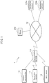
- Fig. 1 is a diagram showing an embodiment of the monitoring system disclosed herein.
- Fig. 2 is a diagram showing a patient using an oxygen concentrator and a measuring apparatus.
- Fig. 3 is a diagram showing a state where an SpO 2 measuring apparatus is fitted onto the finger of a patient.
- the monitoring system 1 of this embodiment comprises an oxygen concentrator 10, a respiration detector 11, a percutaneous arterial blood oxygen saturation meter (SpO 2 meter) 12, a communication terminal 13, a server 20 and monitoring terminals 30a, 30b.
- a patient 40 uses the oxygen concentrator 10 to carry out Home Oxygen Therapy, by continuous inhalation of oxygen-enriched gas at home.
- the oxygen concentrator 10 is an apparatus that separates nitrogen in the air to supply high-concentration oxygen (oxygen-enriched gas), for use mainly in Home Oxygen Therapy.
- the oxygen concentrator 10 may be a pressure fluctuation adsorption-type oxygen concentrator which has an adsorption tube (not shown) packed with molecular sieve zeolite or lithium-based zeolite, as an adsorbent capable of selectively adsorbing nitrogen over oxygen, and supplies the pressurized air created by an air compressor (not shown) to extract the oxygen.
- the oxygen produced by the oxygen concentrator 10 is supplied to the patient 40 using a cannula 14.
- the flow rate of the oxygen supplied by the oxygen concentrator 10 can be controlled using an operating unit (not shown).
- the flow rate of oxygen supplied by the oxygen concentrator 10 can usually be set based on a physician's prescription.
- the oxygen concentrator 10 uses a communication terminal 13 to send operation data indicating the state of operation of the apparatus, through a network N to the server 20.
- the oxygen concentrator 10 communicates with the communication terminal 13 through a communication line, for example.
- the communication terminal 13 sends the operation data received from the oxygen concentrator 10 to the server 20, through the network N by wired or wireless communication.
- the state of operation of the oxygen concentrator 10 may include, for example, the set value for the oxygen flow rate, and a cannula bend alarm notification.
- the set value for the oxygen flow rate is the oxygen flow rate that has been set for the oxygen concentrator 10.
- a cannula bend alarm notification is a notification indicating a state in which the patient 40 cannot be supplied with sufficient generated oxygen through the cannula due to bending of the cannula.
- the oxygen concentrator 10 may also detect the respiration rate of the patient 40 as a state of operation.
- a respiration detector 11 is provided within the cannula 14.
- the respiration detector 11 detects movement of gas through the cannula 14 and measures the state of use of the patient 40 who is using the oxygen concentrator, such as the respiration rate of the patient 40.
- the respiration detector 11 sends the measured usage data to the server 20 through the network N, using the communication terminal 13.
- the respiration detector 11 communicates with the communication terminal 13 via short-range wireless communication, for example.
- the communication terminal 13 sends the usage data received from the respiration detector 11 to the server 20, through the network N by either wired or wireless communication.
- the usage data measured by the respiration detector 11 may be, for example, a respiration detection notification, notifying that respiration of the user has been detected, a cannula dislocation notification, notifying that the cannula has been dislocated, and the respiration rate.
- a respiration detection notification means detection of a state in which oxygen is being supplied to the patient 40 through the cannula 14 and respiration by the patient 40 has been detected.
- a cannula dislocation notification means detection of a state in which oxygen is being supplied to the patient 40 through the cannula 14, but respiration by the patient 40 is not detected.
- the respiration rate is the respiration rate per unit time.
- the SpO 2 meter 12 has a device body 12a, a probe section 12b, and a cable 12c connecting the device body 12a and the probe section 12b.
- the SpO 2 meter 12 has the probe section 12b fitted onto a finger of the patient 40, and measures the state of use by the patient 40 using the oxygen concentrator, as the SpO 2 value for blood flowing through the artery of the finger.
- the SpO 2 meter 12 sends the measured usage data to the server 20 through the network N, using the communication terminal 13.
- the SpO 2 meter 12 communicates with the communication terminal 13 using short-range wireless communication, for example.
- the communication terminal 13 sends the usage data received from the SpO 2 meter 12, to the server 20 through the network N, by wired or wireless communication.
- the usage data measured by the SpO 2 meter 12 may include the SpO 2 value, pulse rate and acceleration, for example.
- the SpO 2 meter 12 measures the median or mean value for the SpO 2 as the recorded SpO 2 value.
- the pulse rate is the pulse rate per unit time.
- the acceleration is measured using an accelerometer in the SpO 2 meter 12, the server 20 determining the physical activity of the patient 40 based on the acceleration.
- the server 20 receives usage data and operation data for the patient 40, and generates message information when either or both the usage data and operation data fail to satisfy the predetermined monitoring conditions.
- the server 20 also generates display information for the message information together with the usage data and operation data relating to the patient 40, and sends it to the monitoring terminals 30a, 30b through the network N.
- the monitoring terminals 30a, 30b receive the display information for the message information together with the usage data and operation data relating to the patient 40, and display it.
- the monitoring terminal 30a is installed at the medical institution and is used by the physician in charge of the patient 40.
- the physician in charge of the patient 40 can focus on the usage data or operation data for which message information was generated, which is displayed by the monitoring terminal 30a, to easily understand the state of use of the oxygen concentrator 10 and the condition of the patient 40.
- the physician may also compare the prescription written for the patient 40 with the usage data and operation data to confirm the state of use of the oxygen concentrator 10, the health condition of the patient 40 and compliance of the patient 40.
- the physician can thus confirm the therapeutic effect of the Home Oxygen Therapy for the patient 40, as support for devising future treatment policy for the patient 40.
- the monitoring terminal 30b may also be used by medical personnel, for example, instead of a physician. Medical personnel other than a physician can also focus on the usage data or operation data for which message information was generated, to easily understand the condition of the patient 40. This will allow them to determine the necessary support or environment to be provided for the patient 40.
- the physician in charge of the patient 40 using the monitoring terminal 30a, can authorize reception of the messages and the usage data and operation data for the patient 40 from the server 20, by the monitoring terminal 30b. This can prevent third parties from accessing personal information of the patient 40.
- Fig. 4 is a diagram showing a server configuration.
- the server 20 has a processing unit 21, a memory 22, a display 23, an operating unit 24 and a communication unit 25.
- the processing unit 21 has one or more processors, and a peripheral circuit.
- the processing unit 21 performs control of the hardware components of the server 20, and various processing, according to a predetermined computer program prestored in the memory 22, and uses the memory 22 for temporary storage of the data produced during processing.
- the memory 22 may have a semiconductor memory such as a random access memory (RAM) or read-only memory (ROM), or a magnetic disk or flash memory.
- the memory 22 may also have a drive that is able to read a storage medium with non-temporary storage of a predetermined computer program.
- the memory 22 stores and associates identifying information for identification of the patient (patient ID), such as the patient name, birth date and gender, prescription information such as the oxygen flow rate, and future outpatient scheduling.
- the display 23 is controlled by the processing unit 21 to display the various information.
- a liquid crystal display for example, may be used as the display 23.
- the operating unit 24 is operated by the user, allowing input operation.
- a keyboard or mouse, for example, may be used as the operating unit 24.
- the communication unit 25 sends and receives information between the communication terminal 13 and the monitoring terminals 30a, 30b via the network N.
- the processing unit 21 carries out various processing based on the information received using the communication unit 25.
- the processing unit 21 sends results of the various processing using the communication unit 25.
- the communication unit 25 may have a communication circuit and communication line for sending and receiving.
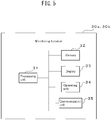
- Fig. 5 is a diagram showing monitoring terminals 30a, 30b.
- the monitoring terminals 30a, 30b have a processing unit 31, a memory 32, a display 33, an operating unit 34 and a communication unit 35.
- the processing unit 31 has one or more processors, and a peripheral circuit.
- the processing unit 31 performs control of the hardware components of the monitoring terminals 30a, 30b, and various processing, according to a predetermined computer program prestored in the memory 32, and uses the memory 32 for temporary storage of the data produced during processing.
- the memory 32 may have a semiconductor memory such as a random access memory (RAM) or read-only memory (ROM), or a magnetic disk or flash memory.
- the memory 32 may also have a drive that is able to read a storage medium with non-temporary storage of a predetermined computer program.
- the display 33 is controlled by the processing unit 31 to display the various information.
- a liquid crystal display for example, may be used as the display 33.
- the operating unit 34 is operated by the user, allowing input operation.
- a keyboard or mouse, for example, may be used as the operating unit 34.
- the communication unit 35 sends and receives information with the server 20 via the network N.
- the processing unit 31 carries out various processing based on the information received using the communication unit 35.
- the processing unit 21 sends results of the various processing using the communication unit 35.
- the communication unit 35 may have a communication circuit and communication line for sending and receiving.
- a physician at a medical institution operates the monitoring terminal 30a and inputs a direction guide threshold for a patient.
- the monitoring terminal 30a sends the direction guide threshold that the physician has input, together with the patient ID, for example, through the network N to the server 20.
- the direction guide threshold is an example of patient monitoring conditions relating to usage data and operation data.
- the direction guide threshold can be set for different individual patients.
- the direction guide threshold can also be set to be a common value for all patients overseen by the physician.
- the direction guide threshold can even be set to be a common value for all patients at the medical institution to which the physician belongs.
- the direction guide threshold may be set for all of the usage data and operation data, or set for only a portion of the usage data or operation data.
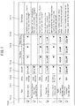
- Fig. 7 is a screen 700 for the display 33 of the monitoring terminal 30a.
- the screen 700 displays a screen for input of direction guide thresholds.
- the screen 700 has an item column 701, a units column 702, an overall direction guide threshold column 703 spanning a predetermined period during which the oxygen concentrator 10 has been used, a direction guide threshold column 704 during resting periods during each day of use, a direction guide threshold column 705 for exertion periods during each day of use, a direction guide threshold column 706 for sleeping periods during each day of use, a direction guide threshold definition column 707, and a check column 708.
- Each item in the item column 701 is an item of information that can be obtained or calculated by the server 20 based on the operation data or usage data.
- the direction guide thresholds for each item are input with the units indicated in the units column 702.
- the "inhalation time" in the item column 701 is the time during which the patient has inhaled oxygen using the oxygen concentrator 10.
- a direction guide threshold for the inhalation time is set as a lower limit for the daily use average, obtained by dividing the sum of the inhalation times for each day of use during the predetermined period during which the oxygen concentrator 10 has been used, by the number of days of use (direction guide threshold column 703).
- 20 hours is set as the direction guide threshold for the inhalation time.
- a direction guide threshold for the inhalation time is also set as a lower limit for the daily use average for inhalation time when the oxygen concentrator 10 has been operated at the oxygen flow rate during resting periods, within the predetermined period during which the oxygen concentrator 10 is used (direction guide threshold column 704).
- a direction guide threshold for the inhalation time is similarly set as a lower limit for the daily use average for inhalation time when the oxygen concentrator 10 has been operated at the oxygen flow rate for exertion periods, within the predetermined period during which the oxygen concentrator 10 is used (direction guide threshold column 705).
- a direction guide threshold for the inhalation time is also set as a lower limit for the daily use average for inhalation time when the oxygen concentrator 10 has been operated at the oxygen flow rate for sleeping periods, within the predetermined period during which the oxygen concentrator 10 is used (direction guide threshold column 706).
- the server 20 generates message information when the inhalation time falls below any of the direction guide thresholds.
- the non-prescription flow rate operating time in the item column 701 is the time during which the oxygen concentrator 10 has been operated at an oxygen flow rate outside of the flow rate prescribed by the physician.
- the physician's prescription determines the oxygen flow rate during resting periods, the oxygen flow rate during exertion periods and the oxygen flow rate during sleeping periods for each patient.
- the memory 22 of the server 20 stores the oxygen flow rate during resting periods, the oxygen flow rate during exertion periods and the oxygen flow rate during sleeping periods, in association with the patient ID.
- the server 20 assesses that the oxygen concentrator 10 is being operated at a non-prescription flow rate.
- the direction guide threshold for the non-prescription flow rate operating time is set as the upper limit for the daily use average of operating time in which the oxygen concentrator 10 has been operated at a non-prescription flow rate, within the predetermined period during which the oxygen concentrator 10 is used. In the example shown in Fig. 7 , 30 minutes is set as the direction guide threshold for the non-prescription flow rate operating time.
- the server 20 generates message information when the non-prescription flow rate operating time is above the direction guide threshold for the non-prescription flow rate operating time.
- the operation time in item column 701 is the time during which the oxygen concentrator 10 has been operated.
- a direction guide threshold for the operation time is first set as a lower limit for the daily use average for operation time when the oxygen concentrator 10 has been operated, within the predetermined period during which the oxygen concentrator 10 is used (direction guide threshold column 703).
- a direction guide threshold for the operation time is also set as a lower limit for the daily use average for operation time when the oxygen concentrator 10 has been operated at the oxygen flow rate during resting periods, within the predetermined period during which the oxygen concentrator 10 is used (direction guide threshold column 704).
- a direction guide threshold for the operation time is also set as a lower limit for the daily use average for operation time when the oxygen concentrator 10 has been operated at the oxygen flow rate during oxygen flow rate during exertion periods, within the predetermined period during which the oxygen concentrator 10 is used (direction guide threshold column 705).
- a direction guide threshold for the operation time is similarly set as a lower limit for the daily use average for operation time when the oxygen concentrator 10 has been operated at the oxygen flow rate during sleeping periods, within the predetermined period during which the oxygen concentrator 10 is used (direction guide threshold column 706).
- the server 20 generates message information when the operation time falls below any of the direction guide thresholds for the operation time.
- a direction guide threshold for the cannula dislocation time in item column 701 is first set as an upper limit for the daily use average for operation time when the oxygen concentrator 10 has been operated in a state where cannula dislocation has been detected, within the predetermined period during which the oxygen concentrator 10 is used (direction guide threshold column 703). In the example shown in Fig. 7 , 2 hours is set as the direction guide threshold for the cannula dislocation time.
- a direction guide threshold for the cannula dislocation time is also set as an upper limit for the daily use average for operation time when the oxygen concentrator 10 has been operated at the oxygen flow rate during resting periods in a state where cannula dislocation has been detected, within the predetermined period during which the oxygen concentrator 10 is used (direction guide threshold column 704).
- 30 minutes is set as the direction guide threshold for the cannula dislocation time.
- a direction guide threshold for the cannula dislocation time is also set as an upper limit for the daily use average for operation time when the oxygen concentrator 10 has been operated at the oxygen flow rate during exertion periods in a state where cannula dislocation has been detected, within the predetermined period during which the oxygen concentrator 10 is used (direction guide threshold column 705).
- 30 minutes is set as the direction guide threshold for the cannula dislocation time.
- a direction guide threshold for the cannula dislocation time is also set as an upper limit for the daily use average for operation time when the oxygen concentrator 10 has been operated at the oxygen flow rate during sleeping periods in a state where cannula dislocation has been detected, within the predetermined period during which the oxygen concentrator 10 is used (direction guide threshold column 706).
- 1 hour is set as the direction guide threshold for the cannula dislocation time.
- the server 20 generates message information when the cannula dislocation time is above any of the direction guide thresholds for the cannula dislocation time.
- the cannula bend alarm count in the item column 701 is the number of cannula bend alarms that have been generated during the predetermined period during which the oxygen concentrator 10 is used.
- a direction guide threshold for the cannula bend alarm count is first set as the upper limit for the number of cannula bend alarms that have been generated during the predetermined period during which the oxygen concentrator 10 is used (direction guide threshold column 703).
- a direction guide threshold for the cannula bend alarm count is also set as an upper limit for the number of cannula bend alarms generated when the oxygen concentrator 10 has been operated at the oxygen flow rate during resting periods, within the predetermined period during which the oxygen concentrator 10 is used (direction guide threshold column 704).
- a direction guide threshold for the cannula bend alarm count is also set as an upper limit for the number of cannula bend alarms generated when the oxygen concentrator 10 has been operated at the oxygen flow rate during exertion periods, within the predetermined period during which the oxygen concentrator 10 is used (direction guide threshold column 705).
- a direction guide threshold for the cannula bend alarm count is similarly set as an upper limit for the number of cannula bend alarms generated when the oxygen concentrator 10 has been operated at the oxygen flow rate during sleeping periods, within the predetermined period during which the oxygen concentrator 10 is used (direction guide threshold column 706).
- the server 20 generates message information when the cannula bend alarm count is above any of the direction guide thresholds for the cannula bend alarm count.
- the SpO 2 value in the item column 701 can be set as a median value or an average value.
- the direction guide threshold for the SpO 2 value is first set as the lower limit for the daily use average of the SpO 2 value, within the predetermined period during which the oxygen concentrator 10 is used (direction guide threshold column 703). In the example shown in Fig. 7 , the direction guide threshold for the SpO 2 value is set to 85%.
- the direction guide threshold for the SpO 2 value is also set as a lower limit for the daily use average for the SpO 2 value measured when the oxygen concentrator 10 has been operated at the oxygen flow rate during resting periods, within the predetermined period during which the oxygen concentrator 10 is used (direction guide threshold column 704). In the example shown in Fig.
- the direction guide threshold for the SpO 2 value is set to 85%.
- the direction guide threshold for the SpO 2 value is also set as a lower limit for the daily use average for the SpO 2 value measured when the oxygen concentrator 10 has been operated at the oxygen flow rate during exertion periods, within the predetermined period during which the oxygen concentrator 10 is used (direction guide threshold column 705).
- the direction guide threshold for the SpO 2 value is set to 85%.
- the direction guide threshold for the SpO 2 value is also set as a lower limit for the daily use average for the SpO 2 value measured when the oxygen concentrator 10 has been operated at the oxygen flow rate during sleeping periods, within the predetermined period during which the oxygen concentrator 10 is used (direction guide threshold column 706).
- the direction guide threshold for the SpO 2 value is set to 85%.
- the server 20 generates message information when the SpO 2 value falls below any of the direction guide thresholds for the SpO 2 value.
- the pulse rate in the item column 701 can be set as a median value or an average value.
- a direction guide threshold for the pulse rate is first set as a lower limit for the daily use average for the pulse rate within the predetermined period during which the oxygen concentrator 10 is used (direction guide threshold column 703).
- 80 bpm is set as the direction guide threshold for the pulse rate.
- the direction guide threshold for the SpO 2 value is also set as a lower limit for the daily use average for the SpO 2 value measured when the oxygen concentrator 10 has been operated at the oxygen flow rate during resting periods, within the predetermined period during which the oxygen concentrator 10 is used (direction guide threshold column 704).
- the direction guide threshold for the SpO 2 value is also set as a lower limit for the daily use average for the SpO 2 value measured when the oxygen concentrator 10 has been operated at the oxygen flow rate during exertion periods, within the predetermined period during which the oxygen concentrator 10 is used (direction guide threshold column 705).
- 80 bpm is set as the direction guide threshold for the pulse rate.
- the direction guide threshold for the SpO 2 value is also set as a lower limit for the daily use average for the pulse rate measured when the oxygen concentrator 10 has been operated at the oxygen flow rate during sleeping periods, within the predetermined period during which the oxygen concentrator 10 is used (direction guide threshold column 706).
- 80 bpm is set as the direction guide threshold for the pulse rate.
- the server 20 generates message information when the pulse rate falls below any of the direction guide thresholds for the pulse rate.
- the check column 708 indicates whether or not a direction guide threshold has been set for each item in the item column 708. An item that is checked in the check column 708 has a direction guide threshold set, and one that is not checked does not have any direction guide threshold set.
- direction guide thresholds are set for the inhalation time, the non-prescription flow rate operating time, the cannula dislocation time, the SpO 2 value and the pulse rate.
- No direction guide threshold is set for the operation time and cannula bend alarm count.
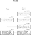
- step S603 the server 20 stores the received direction guide thresholds for each item in a memory 22 associated with the patient ID.
- the oxygen concentrator 10 begins sending the patient ID and operation data to the server 20 through the network N, using the communication terminal 13. For example, the oxygen concentrator 10 sends operation data to the server 20 at predetermined intervals, or after a change in the state of operation has taken place.
- the server 20 stores the received operation data in association with the patient ID.
- the server 20 assesses that the patient has used the oxygen concentrator 10, and adds it as a day of use.
- the server 20 also discriminates between resting period operation, exertion period operation and sleeping period operation, based on the set value for the oxygen flow rate received from the oxygen concentrator 10.
- the server 20 also calculates the operation time of the oxygen concentrator 10 based on the date and time of the operation data received from the oxygen concentrator 10.
- the server 20 further calculates the non-prescription flow rate operating time based on the set value for the oxygen flow rate received from the oxygen concentrator 10, and the reception date and time.
- the server 20 still further calculates the flow switching count, which is the number of times that setting of the oxygen flow rate has been changed, based on the set values for the oxygen flow rate received from the oxygen concentrator 10.
- the server 20 determines the cannula bend alarm count during a predetermined period, based on cannula bend alarm notifications received from the oxygen concentrator 10.
- the respiration detector 11 begins sending the patient ID and the measured usage data to the server 20 through the network N, using the communication terminal 13. For example, the respiration detector 11 sends usage data to the server 20 at predetermined intervals, or when a change in usage data has occurred.
- the server 20 stores the received usage data in association with the patient ID.
- the server 20 calculates the oxygen inhalation time based on the date and time when the respiration detection notification has been received as usage data.
- the server 20 also calculates the cannula dislocation time, based on the date and time when the cannula dislocation notification has been received, as usage data.
- the cannula dislocation time is presumed to be the time of the state in which the patient 40 has not inhaled oxygen.
- the SpO 2 meter 12 begins sending the patient ID and the measured usage data to the server 20 through the network N, using the communication terminal 13. For example, the SpO 2 meter 12 sends usage data to the server 20 at predetermined intervals, or when a change in usage data has occurred.
- the server 20 stores the received usage data in association with the patient ID.
- the server 20 calculates the amount of movement of the patient based on the acceleration, as received usage data, and estimates the physical activity of the patient based on the amount of movement.
- the server 20 analyzes the usage data and operation data for each patient by comparing it with the direction guide thresholds stored in the memory 22, and generates message information when the usage data fails to satisfy the conditions stipulated by the direction guide thresholds and/or when the operation data fails to satisfy the conditions stipulated by the direction guide thresholds.
- the message information may also include, for example, a notification that usage data and/or operation data has fallen outside the conditions stipulated by the direction guide threshold, or a proposal to monitor the condition of the patient, or a proposal to re-evaluate the manner in which the oxygen concentrator 10 is to be used by the patient.
- Generation of the message information may also include generating display information in which usage data or operation data that does not satisfy the conditions stipulated by the direction guide thresholds is displayed in a visibly enhanced manner.
- Generation of the message information may also include selecting one or more items of message information from among previously prepared message information items, based on the usage data or operation data that does not satisfy the conditions stipulated by the direction guide thresholds.
- the server 20 may also generate message information based on the usage data and operation data. For example, when the inhalation time has fallen below the direction guide threshold and the non-prescription flow rate operating time is above the direction guide threshold, the server 20 may generate message information reading: "Please confirm patient compliance, or re-evaluate prescription if necessary". When the non-prescription flow rate operating time has fallen below the direction guide threshold and the non-prescription flow rate operating time is above the direction guide threshold, it is possible that the patient is not carrying out oxygen inhalation based on the prescription, and therefore presumably compliance should be ensured, or it may be necessary to re-evaluate the prescription.
- the server 20 may generate message information reading: "Confirm condition of patient immediately".
- the SpO 2 value has fallen below the direction guide threshold and the pulse rate has fallen below the direction guide threshold, it is possible that the patient may be in a dangerous state of health, and therefore it may be necessary for the physician or medical personnel to immediately confirm the condition of the patient.
- message information to be generated by the server 20 when the non-prescription flow rate operating time is above the direction guide threshold, the server 20 may generate message information reading: "Excessive time operating at non-prescription flow rate”. When the pulse rate is above the direction guide threshold, the server 20 may generate message information reading: "Pulse rate exceeds target value”. When the non-prescription flow rate operating time is above the direction guide threshold and the SpO 2 value has fallen below the direction guide threshold, the server 20 may generate message information reading: "SpO 2 value has fallen. Please take note of non-prescription flow rate operating time”.
- the server 20 may generate message information reading: "SpO 2 value is low and respiration rate has increased. Please confirm patient compliance, or re-evaluate prescription if necessary".
- the generated message information is not limited to the particular instances described above.
- step S613 the physician at the medical institution uses the monitoring terminal 30a to send a review request to review the message information together with the usage data and operation data for the patient in their charge, along with the desired review period and the patient ID, to the server 20 through the network N.
- the server 20 In the following step S615, the server 20 generates display information that, based on the received review request, displays message information together with the usage data and operation data for the patient under the charge of the physician, and sends it to the monitoring terminal 30a through the network N.
- the monitoring terminal 30a displays the message information, together with the usage data and operation data of the patient under the charge of the physician, on the display 33, based on the received display information.
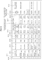
- Fig. 8 is a diagram showing the screen 800 of a display 33 that displays the overall situation for the state of operation and state of use for a patient under the charge of a physician.
- the screen 800 shows information of different items over a predetermined period during which an oxygen concentrator 10 has been used, for each of the patients under the charge of the physician.
- the screen 800 has a patient ID column 801, a patient name column 802, a patient gender column 803, a used day count column 804 for the oxygen concentrator 10, an operating time column 805 for the oxygen concentrator 10, a cannula dislocation time column 806, a cannula bend alarm count column 807, a non-prescription flow rate operating time column 808, an SpO 2 value column 809, a patient next scheduled outpatient date column 810 and a check column 811.
- the patient ID and patient birth date are displayed in the patient ID column 801.
- the server 20 accesses information stored in the memory 22, based on the patient ID in the review request, reads out the patient ID and patient birth date that are to be displayed in the patient ID column 801, and generates the display information in the patient ID column 801.
- the server 20 generates display information for the patient name column 802 and patient gender column 803 in a similar manner.
- the used day count column 804 the number of days of use of the oxygen concentrator 10 is displayed for each patient.
- the server 20 accesses information stored in the memory 22, based on the patient ID, and generates display information for the number of days of use over the predetermined period during which the oxygen concentrator 10 has been used.
- the daily use average for the operation time over the predetermined period during which the oxygen concentrator 10 has been used is displayed, for each patient.
- the server 20 accesses information stored in the memory 22, based on the patient ID, and generates display information for the daily use average for the operation time of the oxygen concentrator 10.
- the daily use average for cannula dislocation time over the predetermined period during which the oxygen concentrator 10 has been used is displayed, for each patient.
- the server 20 accesses information stored in the memory 22, based on the patient ID, and generates display information for the daily use average for cannula dislocation time.
- the cannula bend alarm count column 807 the cannula bend alarm count over the predetermined period during which the oxygen concentrator 10 has been used is displayed, for each patient.
- the server 20 accesses information stored in the memory 22, based on the patient ID, and generates display information for the cannula bend alarm count.
- the daily use average for the non-prescription flow rate operating time over the predetermined period during which the oxygen concentrator 10 has been used is displayed, for each patient.
- the server 20 accesses information stored in the memory 22, based on the patient ID, and generates display information for the daily use average for non-prescription flow rate operating time.
- the daily use average for the SpO 2 value over the predetermined period during which the oxygen concentrator 10 has been used is displayed, for each patient.
- the server 20 accesses information stored in the memory 22, based on the patient ID, and generates display information for the daily use average for the SpO 2 value.
- next scheduled outpatient date column 810 the next scheduled outpatient date is displayed for each patient.
- the server 20 accesses information stored in the memory 22, based on the patient ID, and generates display information for the next scheduled outpatient date.
- the generated message information is displayed on the screen 800, for each item of each patient.
- the message information is generated as display information to be displayed with the item information visibly enhanced.
- the screen 800 shown in Fig. 8 is merely an example, and the invention is not limited to the screen 800 example shown in Fig. 8 .
- step S619 when it is desired to confirm the details of the operation data and usage data relating to use of the oxygen concentrator 10 for one patient, the physician checks the check column 811 of that patient using the monitoring terminal 30a.
- the monitoring terminal 30a sends the checked patient ID and a detailed review request, requesting detailed display information for the message information, usage data and operation data, to the server 20.
- step S621 upon receiving the patient ID and the detailed review request, the server 20 generates detailed display information for the message information, usage data and operation data relating to the patient identified by the patient ID, and sends it to the monitoring terminal 30a.
- the monitoring terminal 30a displays the detailed display information for the message information, usage data and operation data of the patient on the display 33, based on the received detailed display information.
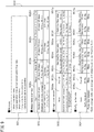
- Fig. 9 is a diagram showing a display screen 900 of a display 33 that displays the detailed situation for the state of operation and state of use for a patient.
- the screen 900 has a message column 901, a usage overview table 902, a usage details table 903 and an SpO 2 ⁇ pulse rate table 904.
- Generated message information is displayed in the message column 901.
- the message information displayed in the message column 901 has been generated for items that fail to satisfy the conditions stipulated by the overall direction guide threshold column 703 for the predetermined period during which the oxygen concentrator 10 has been used, shown in the screen 700, as a number of messages that can be displayed in an easily visible manner in the message column 901.
- the number of message information items displayed in the message column 901 may be set as appropriate for the dimensions of the message column 901, for example. For example, all of the generated message information items may be displayed in the message column 901.
- message information items generated for the inhalation time, the non-prescription flow rate operating time, the operation time, the cannula dislocation time and the cannula bend alarm count are displayed in the message column 901.
- the usage overview table 902 has an item column 902a, a first period column 902b, a second period column 902c and a third period column 902d.
- the number of days of use of the oxygen concentrator 10, the inhalation time, the flow switching count and the non-prescription flow rate operating time for a predetermined period are displayed in the item column 902a.
- the information items other than the number of days of use displayed in the usage overview table 902 are daily use averages for the predetermined period during which the oxygen concentrator 10 has been used.
- Each information item for the period from March 1 to March 30 is displayed in the first period column 902b.
- Message information for the inhalation time and non-prescription flow rate operating time is generated, and the information items are displayed in a visibly enhanced manner in the first period column 902.
- Information for each item during the period of January 30 to February 28 is displayed in the second period column 902c.
- Information for each item during the period of December 31 to January 29 is displayed in the third period column 902d.
- the usage details table 903 has an item column 903a, an overall information column 903b in which the daily use average or cumulative value for each item during the predetermined period during which the oxygen concentrator 10 has been used is displayed, a resting period information column 903c in which the daily use average or cumulative value for each item during resting periods is displayed, an exertion period information column 903d in which the daily use average or cumulative value for each item during exertion periods is displayed, an "other information column” 903e in which the daily use average or cumulative value for each item during other periods of the day is displayed, a sleeping period information column 903f in which the daily use average or cumulative value for each item during sleeping periods is displayed, and an “other information column” 903g in which the daily use average or cumulative value for each item during other periods of the night is displayed.
- the operation time, the cannula dislocation time and the cannula bend alarm count are displayed in the item column 903a.
- the daily use average or cumulative value for each item during periods other than resting periods and exertion periods is displayed.
- the daily use average or cumulative value for each item with an oxygen flow rate in periods other than sleeping periods is displayed.
- “night” is defined as the period from 10:00 pm to 5:00 am
- “day” is defined as the period from 5:00 am to 10:00 pm.
- message information is generated for the operation time, the cannula dislocation time and the cannula bend alarm count, and the item information is displayed in a visibly enhanced manner.
- the SpO 2 pulse rate table 904 has an item column 904a, an overall information column 904b in which the daily use average for each item in the predetermined period during which the oxygen concentrator 10 has been used is displayed, a resting period information column 904c in which the daily use average for each item during resting periods is displayed, an exertion period information column 904d in which the daily use average 4 for each item during exertion periods is displayed, an "other information column” 904e in which the daily use average 4 for each item during other periods of the day is displayed, a sleeping period information column 904f in which the daily use average 4 for each item during sleeping periods is displayed, and an "other information column” 904g in which the daily use average 4 for each item during other periods of the night is displayed.
- the physician is able to confirm, on the same screen, both the message information and the usage data and/or operation data for which message information has been generated, thus facilitating overall observation of the condition of the patient.
- the screen 900 shown in Fig. 9 is merely an example, and the invention is not limited to the screen 900 example shown in Fig. 9 .
- step S625 if it is desired to confirm the time series information for the message information, usage data and operation data relating to use of the oxygen concentrator 10 by a single patient, the physician sends a time series review request, requesting review of the time series information, together with the patient ID.
- step S627 upon receiving the patient ID and the time series review request, the server 20 generates display information for the time series information for the message information, usage data and operation data relating to the patient identified by the patient ID, and sends it to the monitoring terminal 30a.
- the monitoring terminal 30a displays the display information for the time series information for the message information, usage data and operation data of the patient identified by the patient ID, on the display 33, based on the received display information for the time series information.
- Fig. 10 is a diagram showing a screen 1000 of a display 33 that displays the state of operation and state of use for a patient, in a time series.
- the screen 1000 has a first time series information region 1001 and a second time series information region 1002.
- a time series is displayed horizontally for the dates for which usage data and operation data have been acquired, with the set values for the oxygen flow rate being displayed vertically in a time series for each date of acquisition.
- the set values for the oxygen flow rate are classified by resting period 1001a, exertion period 1001b, sleeping period 1001c and non-prescription 1001d.
- usage data and operation data are displayed vertically in a time series for each date of acquisition.
- cannula dislocation occurrence 1001e, cannula bend alarm occurrence 1001f and generation of SpO 2 value message information 1001g are displayed in a time series.
- a date 1001h in which the prescription for the patient was changed is displayed.
- the dates of acquisition for which usage data and operation data have been acquired are displayed in a time series, showing whether or not message information has been generated for a predetermined item for each date of acquisition.
- the non-prescription flow rate operating time, cannula dislocation time and cannula bend alarm count are displayed as items.
- Dates of acquisition without generation of message information are displayed as being outside of the direction guide threshold 1002b, and dates of acquisition with generation of message information are displayed as being within the direction guide threshold 1002a.
- no direction guide threshold value has been set for the cannula dislocation time, it is displayed as having an unset direction guide threshold 1002d. Dates for which usage data and operation data items have not been acquired are indicated as having no data 1002c.
- the screen 1000 shown in Fig. 10 is merely an example, and the invention is not limited to the screen 1000 example shown in Fig. 10 .
- the monitoring system of the embodiment described above can monitor usage data indicating the state of use by a patient using the oxygen concentrator and operation data indicating the state of operation of the oxygen concentrator, and can notify a monitoring person, such as a physician, by generation of a message when predetermined monitoring conditions fail to be satisfied.
- the monitoring terminal 30a is used by the physician in charge of the patient.
- the monitoring terminal 30b may also be used by medical personnel instead of the physician, under the supervision of the physician. Medical personnel other than the physician can also operate the monitoring terminal 30b to observe the usage data and operation data shown in Fig. 8 to Fig. 11 . This will allow the physician and medical personnel other than the physician to share patient information, thus aiding them in efficiently establishing future treatment policy for the patient and providing the necessary support and environment for the patient.
- the server, monitoring system, terminal, monitoring device and method of the embodiment described above according to the invention may implement appropriate modifications such as are within the scope of the gist thereof.
- the operation data for the oxygen concentrator and the usage data for the measuring apparatus are merely examples, and the invention is not limited to those oxygen concentrator operation data and measuring apparatus usage data.
- the monitoring system in the embodiment described above comprises two monitoring terminals, but the number of monitoring terminals is not limited to two. It is sufficient for the monitoring system to comprise at least one monitoring terminal, or it may comprise three or more monitoring terminals.
- a plurality of monitoring terminals may also be disposed at different medical institutions to allow their use by different physicians. This will allow the condition of the patient to be examined by more than one physician with different specialties.
- the monitoring terminal displays message information, usage data and operation data on a display
- the server functioning as a monitoring device, may instead output the message information, usage data and operation data using an output device such as a server display.
- the embodiment described above also has the server generate message information when either or both the usage data and operation data fail to satisfy the monitoring conditions, but the monitoring terminal or server, as a monitoring device, may instead input the usage data and operation data using an input device such as a communication unit, the processing unit of the monitoring terminal or server generating message information when either or both the usage data and operation data fail to satisfy the monitoring conditions, and using an output device such as a monitoring terminal or server display to output the message information, usage data and operation data.
- an input device such as a communication unit
- the processing unit of the monitoring terminal or server generating message information when either or both the usage data and operation data fail to satisfy the monitoring conditions
- an output device such as a monitoring terminal or server display to output the message information, usage data and operation data.
Landscapes
- Health & Medical Sciences (AREA)
- Engineering & Computer Science (AREA)
- Life Sciences & Earth Sciences (AREA)
- Biomedical Technology (AREA)
- Public Health (AREA)
- General Health & Medical Sciences (AREA)
- Veterinary Medicine (AREA)
- Heart & Thoracic Surgery (AREA)
- Animal Behavior & Ethology (AREA)
- Pulmonology (AREA)
- Emergency Medicine (AREA)
- Physics & Mathematics (AREA)
- Medical Informatics (AREA)
- Hematology (AREA)
- Anesthesiology (AREA)
- Business, Economics & Management (AREA)
- Surgery (AREA)
- Pathology (AREA)
- Molecular Biology (AREA)
- Biophysics (AREA)
- General Business, Economics & Management (AREA)
- Epidemiology (AREA)
- Primary Health Care (AREA)
- Otolaryngology (AREA)
- Physiology (AREA)
- General Physics & Mathematics (AREA)
- Emergency Management (AREA)
- Spectroscopy & Molecular Physics (AREA)
- Optics & Photonics (AREA)
- Computer Networks & Wireless Communication (AREA)
- Dentistry (AREA)
- Oral & Maxillofacial Surgery (AREA)
- Nuclear Medicine, Radiotherapy & Molecular Imaging (AREA)
- Urology & Nephrology (AREA)
- Measuring And Recording Apparatus For Diagnosis (AREA)
- Measurement Of The Respiration, Hearing Ability, Form, And Blood Characteristics Of Living Organisms (AREA)
- Alarm Systems (AREA)
- Medical Treatment And Welfare Office Work (AREA)
Abstract
Description
- The present invention relates to a server, a monitoring system, a terminal, a monitoring device and a method for monitoring of an oxygen concentrator.
- Conventionally, respiration gas supply devices (hereunder also referred to as "oxygen concentrators") have been developed for separating and concentrating oxygen in air for a patient with respiratory disease to obtain oxygen-enriched gas, and oxygen therapy using them has also become common.
- Such oxygen therapy is often carried out while the patient is admitted to a medical institution, but when the patient's respiratory disease exhibits chronic symptoms making it necessary to carry out the oxygen therapy over long periods of time to mitigate and stabilize the symptoms, a treatment method is sometimes carried out in which the oxygen concentrator is set in the patient's home, and a tube called a cannula is used to deliver oxygen-enriched gas supplied by the oxygen concentrator near the nasal cavity of the patient to be inhaled by the patient. This type of treatment method is known as Home Oxygen Therapy, or "HOT".
- Home Oxygen Therapy can be carried out by the steps of: (1) examination of the patient by a physician, (2) issuing of Home Oxygen Therapy instructions by the physician, while also indicate the prescription for the patient based on the examination, (3) setting of an oxygen concentrator in the home of the patient, as indicated in the instructions, (4) continuous inhalation of oxygen-enriched gas using the oxygen concentrator, and (5) periodic examination, such as once a month, by hospital visitation.
- When Home Oxygen Therapy is begun, the physician issues the instructions which contain the prescription for the oxygen therapy to be undergone by the patient. The prescription indicates (1) the oxygen concentration of oxygen-enriched gas to be supplied to the patient, and (2) the flow rate and usage time for the oxygen-enriched gas to be supplied to the patient. Since inhalation of the oxygen-enriched gas is done at the patient's home, the physician cannot directly confirm that inhalation is performed with the indicated gas supply conditions, at the location where the inhalation is being performed. For example, the prescription specifies the oxygen flow rate when the patient is at rest during the day or is under exertion while moving, as well as during nighttime sleeping periods.
- Periodically, such as once a month, the physician must directly meet with the patient during outpatient visitation to confirm whether or not inhalation is being carried out as prescribed, but responses by the patient to the physician's inquiry may in fact differ from the actual state of inhalation.
- Since confirmation of the therapeutic effect of the Home Oxygen Therapy or planning of treatment policy are based on the results of meeting, examining, and questioning the patient by the physician on an outpatient basis, this opens up a risk if the response of the patient to physician inquiry differs from actuality.
-
PTL 1, for example, therefore proposes an oxygen concentrator that holds a recorded history of the supply conditions for oxygen-enriched gas supplied to a patient in Home Oxygen Therapy where oxygen-enriched gas is continuously inhaled at home, as supply history data, thus allowing the supply history data to be confirmed at a medical institution. - [PTL 1] International Patent Publication No.
WO2005/016426 - Because of the many different types of supply history data for supply conditions of oxygen-enriched gas, it is a time-consuming and non-simple procedure for the physician to confirm all of the supply history data at the medical institution.
- From the viewpoint of the physician, it is preferable to not have all of the supply history data of the patient constantly monitored, but rather to have a notification raised only when a certain monitoring parameter does not satisfy the monitoring conditions, so that the physician can study how to respond for the patient who has received the notification.
- Therefore, it may be effective to monitor usage data indicating the state of use by the patient using the oxygen concentrator, and operation data indicating the state of operation of the oxygen concentrator, and to let the monitoring person know when the predetermined monitoring conditions are not satisfied.
- The object of the present specification is provision of a server, monitoring system, terminal, monitoring device and method for monitoring usage data that indicate the state of use by a patient using an oxygen concentrator and operation data indicating the state of operation of the oxygen concentrator.
- The server disclosed herein is a server for monitoring of the state of use of an oxygen concentrator that concentrates oxygen in air and supplies it to a user, the server having a communication unit, and a processing unit that uses the communication unit to receive operation data indicating the state of operation of the oxygen concentrator and usage data for the state of use by the user using the oxygen concentrator, measured by a measuring apparatus, while also generating message information when either or both the usage data and operation data fail to satisfy the monitoring conditions, and sending the message information together with the usage data and operation data, using the communication unit.
- The monitoring system disclosed herein is a monitoring system for monitoring of the state of use of an oxygen concentrator that concentrates oxygen in air and supplies it to a user, the monitoring system having an oxygen concentrator that sends operation data indicating the state of operation, a measuring apparatus that measures and sends usage data indicating the state of use by the user using the oxygen concentrator, a server that receives the usage data and operation data, and when either or both the usage data and operation data fail to satisfy the monitoring conditions, generates message information and sends the message information together with the usage data and operation data, and a terminal that has a display and receives the message information together with the usage data and operation data, displaying them on the display.
- The terminal disclosed herein is a terminal for monitoring of the state of use of an oxygen concentrator that concentrates oxygen in air and supplies it to a user, the terminal having a communication unit, a display, and a processing unit that uses the communication unit to receive from a server, message information generated by the server that has received operation data indicating the state of operation of the oxygen concentrator and usage data for the state of use by the user using the oxygen concentrator, measured by the measuring apparatus, when either or both the usage data and operation data fail to satisfy the monitoring conditions, and also the usage data and operation data, and displays the message information together with the usage data and operation data on the display.
- The monitoring device disclosed herein is a monitoring device for monitoring of the state of use of an oxygen concentrator that concentrates oxygen in air and supplies it to a user, the monitoring device having an input unit, an output unit, and a processing unit which carries out to input operation data indicating the state of operation of the oxygen concentrator and usage data for the state of use by the user using the oxygen concentrator using the input unit, and when either or both the usage data and operation data fail to satisfy the monitoring conditions, carries out to generate message information and output the message information together with the usage data and operation data using the output unit.
- The method disclosed herein is a monitoring method for monitoring of the state of use of an oxygen concentrator that concentrates oxygen in air and supplies it to a user, wherein the method includes obtaining input operation data indicating the state of operation of the oxygen concentrator and usage data for the state of use by the user using the oxygen concentrator, generating message information when either or both the usage data and operation data fail to satisfy the monitoring conditions, and displaying the message information together with the usage data and operation data on a display.
- The server disclosed herein can monitor usage data indicating the state of use by a patient using the oxygen concentrator and operation data indicating the state of operation of the oxygen concentrator, and can notify a monitoring person by generation of a message, when predetermined monitoring conditions fail to be satisfied.
- The monitoring system disclosed herein can also monitor usage data indicating the state of use by a patient using the oxygen concentrator and operation data indicating the state of operation of the oxygen concentrator, and can notify a monitoring person by generation of a message, when predetermined monitoring conditions fail to be satisfied.
- The terminal disclosed herein can likewise monitor usage data indicating the state of use by a patient using the oxygen concentrator and operation data indicating the state of operation of the oxygen concentrator, and can notify a monitoring person by generation of a message, when predetermined monitoring conditions fail to be satisfied.
- The monitoring device disclosed herein can also monitor usage data indicating the state of use by a patient using the oxygen concentrator and operation data indicating the state of operation of the oxygen concentrator, and can notify a monitoring person by generation of a message, when predetermined monitoring conditions fail to be satisfied.
- The method disclosed herein can likewise monitor usage data indicating the state of use by a patient using the oxygen concentrator and operation data indicating the state of operation of the oxygen concentrator, and can notify a monitoring person by generation of a message, when predetermined monitoring conditions fail to be satisfied.
-
-
FIG. 1 is a diagram showing an embodiment of the monitoring system disclosed herein. -
FIG. 2 is a diagram showing a patient using an oxygen concentrator and a measuring apparatus. -
FIG. 3 is a diagram showing a state where an SpO2 measuring apparatus is fitted onto the finger of a patient. -
FIG. 4 is a diagram showing a server configuration. -
FIG. 5 is a diagram showing a monitoring terminal configuration. -
FIG. 6A is a sequence diagram (1) for a monitoring system. -
FIG. 6B is a sequence diagram (2) for a monitoring system. -
FIG. 7 is a diagram showing a display screen for setting of direction guide thresholds. -
FIG. 8 is a diagram showing a display screen that displays the overall situation for the state of operation and state of use for a patient. -
FIG. 9 is a diagram showing a display screen that displays the detailed situation for the state of operation and state of use for a patient. -
FIG. 10 is a diagram showing a display screen that displays the state of operation and state of use for a patient, in a time series. - A referred embodiment of the monitoring system disclosed herein will now be described with reference to the accompanying drawings. However, the technical scope of the invention is not limited to this embodiment, and includes the invention and its equivalents as laid out in the Claims.
-
Fig. 1 is a diagram showing an embodiment of the monitoring system disclosed herein.Fig. 2 is a diagram showing a patient using an oxygen concentrator and a measuring apparatus.Fig. 3 is a diagram showing a state where an SpO2 measuring apparatus is fitted onto the finger of a patient. - The
monitoring system 1 of this embodiment comprises anoxygen concentrator 10, arespiration detector 11, a percutaneous arterial blood oxygen saturation meter (SpO2 meter) 12, acommunication terminal 13, aserver 20 andmonitoring terminals - As shown in
Fig. 2 , apatient 40 uses theoxygen concentrator 10 to carry out Home Oxygen Therapy, by continuous inhalation of oxygen-enriched gas at home. - The
oxygen concentrator 10 is an apparatus that separates nitrogen in the air to supply high-concentration oxygen (oxygen-enriched gas), for use mainly in Home Oxygen Therapy. Theoxygen concentrator 10 may be a pressure fluctuation adsorption-type oxygen concentrator which has an adsorption tube (not shown) packed with molecular sieve zeolite or lithium-based zeolite, as an adsorbent capable of selectively adsorbing nitrogen over oxygen, and supplies the pressurized air created by an air compressor (not shown) to extract the oxygen. - The oxygen produced by the
oxygen concentrator 10 is supplied to thepatient 40 using acannula 14. The flow rate of the oxygen supplied by theoxygen concentrator 10 can be controlled using an operating unit (not shown). The flow rate of oxygen supplied by theoxygen concentrator 10 can usually be set based on a physician's prescription. - The
oxygen concentrator 10 uses acommunication terminal 13 to send operation data indicating the state of operation of the apparatus, through a network N to theserver 20. Theoxygen concentrator 10 communicates with thecommunication terminal 13 through a communication line, for example. - The
communication terminal 13 sends the operation data received from theoxygen concentrator 10 to theserver 20, through the network N by wired or wireless communication. - The state of operation of the
oxygen concentrator 10 may include, for example, the set value for the oxygen flow rate, and a cannula bend alarm notification. The set value for the oxygen flow rate is the oxygen flow rate that has been set for theoxygen concentrator 10. A cannula bend alarm notification is a notification indicating a state in which thepatient 40 cannot be supplied with sufficient generated oxygen through the cannula due to bending of the cannula. Theoxygen concentrator 10 may also detect the respiration rate of the patient 40 as a state of operation. - A
respiration detector 11 is provided within thecannula 14. Therespiration detector 11 detects movement of gas through thecannula 14 and measures the state of use of the patient 40 who is using the oxygen concentrator, such as the respiration rate of thepatient 40. - The
respiration detector 11 sends the measured usage data to theserver 20 through the network N, using thecommunication terminal 13. Therespiration detector 11 communicates with thecommunication terminal 13 via short-range wireless communication, for example. - The
communication terminal 13 sends the usage data received from therespiration detector 11 to theserver 20, through the network N by either wired or wireless communication. - The usage data measured by the
respiration detector 11 may be, for example, a respiration detection notification, notifying that respiration of the user has been detected, a cannula dislocation notification, notifying that the cannula has been dislocated, and the respiration rate. A respiration detection notification means detection of a state in which oxygen is being supplied to the patient 40 through thecannula 14 and respiration by thepatient 40 has been detected. A cannula dislocation notification means detection of a state in which oxygen is being supplied to the patient 40 through thecannula 14, but respiration by thepatient 40 is not detected. The respiration rate is the respiration rate per unit time. - As shown in
Fig. 3 , the SpO2 meter 12 has a device body 12a, aprobe section 12b, and acable 12c connecting the device body 12a and theprobe section 12b. The SpO2 meter 12 has theprobe section 12b fitted onto a finger of thepatient 40, and measures the state of use by the patient 40 using the oxygen concentrator, as the SpO2 value for blood flowing through the artery of the finger. - The SpO2 meter 12 sends the measured usage data to the
server 20 through the network N, using thecommunication terminal 13. The SpO2 meter 12 communicates with thecommunication terminal 13 using short-range wireless communication, for example. - The
communication terminal 13 sends the usage data received from the SpO2 meter 12, to theserver 20 through the network N, by wired or wireless communication. - The usage data measured by the SpO2 meter 12 may include the SpO2 value, pulse rate and acceleration, for example. The SpO2 meter 12 measures the median or mean value for the SpO2 as the recorded SpO2 value. The pulse rate is the pulse rate per unit time. The acceleration is measured using an accelerometer in the SpO2 meter 12, the
server 20 determining the physical activity of the patient 40 based on the acceleration. - The
server 20 receives usage data and operation data for the patient 40, and generates message information when either or both the usage data and operation data fail to satisfy the predetermined monitoring conditions. Theserver 20 also generates display information for the message information together with the usage data and operation data relating to thepatient 40, and sends it to themonitoring terminals - The
monitoring terminals patient 40, and display it. The monitoring terminal 30a is installed at the medical institution and is used by the physician in charge of thepatient 40. - The physician in charge of the patient 40 can focus on the usage data or operation data for which message information was generated, which is displayed by the monitoring terminal 30a, to easily understand the state of use of the
oxygen concentrator 10 and the condition of thepatient 40. The physician may also compare the prescription written for the patient 40 with the usage data and operation data to confirm the state of use of theoxygen concentrator 10, the health condition of thepatient 40 and compliance of thepatient 40. The physician can thus confirm the therapeutic effect of the Home Oxygen Therapy for the patient 40, as support for devising future treatment policy for thepatient 40. - The monitoring terminal 30b may also be used by medical personnel, for example, instead of a physician. Medical personnel other than a physician can also focus on the usage data or operation data for which message information was generated, to easily understand the condition of the
patient 40. This will allow them to determine the necessary support or environment to be provided for thepatient 40. - The physician in charge of the
patient 40, using themonitoring terminal 30a, can authorize reception of the messages and the usage data and operation data for the patient 40 from theserver 20, by the monitoring terminal 30b. This can prevent third parties from accessing personal information of thepatient 40. -
Fig. 4 is a diagram showing a server configuration. - The
server 20 has aprocessing unit 21, amemory 22, adisplay 23, an operatingunit 24 and acommunication unit 25. - The
processing unit 21 has one or more processors, and a peripheral circuit. Theprocessing unit 21 performs control of the hardware components of theserver 20, and various processing, according to a predetermined computer program prestored in thememory 22, and uses thememory 22 for temporary storage of the data produced during processing. - The
memory 22 may have a semiconductor memory such as a random access memory (RAM) or read-only memory (ROM), or a magnetic disk or flash memory. Thememory 22 may also have a drive that is able to read a storage medium with non-temporary storage of a predetermined computer program. Thememory 22 stores and associates identifying information for identification of the patient (patient ID), such as the patient name, birth date and gender, prescription information such as the oxygen flow rate, and future outpatient scheduling. - The
display 23 is controlled by theprocessing unit 21 to display the various information. A liquid crystal display, for example, may be used as thedisplay 23. - The operating
unit 24 is operated by the user, allowing input operation. A keyboard or mouse, for example, may be used as the operatingunit 24. - The
communication unit 25 sends and receives information between thecommunication terminal 13 and themonitoring terminals processing unit 21 carries out various processing based on the information received using thecommunication unit 25. Theprocessing unit 21 sends results of the various processing using thecommunication unit 25. Thecommunication unit 25 may have a communication circuit and communication line for sending and receiving. -
Fig. 5 is a diagram showingmonitoring terminals - The
monitoring terminals processing unit 31, amemory 32, adisplay 33, an operatingunit 34 and acommunication unit 35. - The
processing unit 31 has one or more processors, and a peripheral circuit. Theprocessing unit 31 performs control of the hardware components of themonitoring terminals memory 32, and uses thememory 32 for temporary storage of the data produced during processing. - The
memory 32 may have a semiconductor memory such as a random access memory (RAM) or read-only memory (ROM), or a magnetic disk or flash memory. Thememory 32 may also have a drive that is able to read a storage medium with non-temporary storage of a predetermined computer program. - The
display 33 is controlled by theprocessing unit 31 to display the various information. A liquid crystal display, for example, may be used as thedisplay 33. - The operating
unit 34 is operated by the user, allowing input operation. A keyboard or mouse, for example, may be used as the operatingunit 34. - The
communication unit 35 sends and receives information with theserver 20 via the network N. Theprocessing unit 31 carries out various processing based on the information received using thecommunication unit 35. Theprocessing unit 21 sends results of the various processing using thecommunication unit 35. Thecommunication unit 35 may have a communication circuit and communication line for sending and receiving. - Operation of the
monitoring system 1 described above will now be described with reference toFig. 6A andFig. 6B . - First, in step S601, a physician at a medical institution operates the monitoring terminal 30a and inputs a direction guide threshold for a patient. The monitoring terminal 30a sends the direction guide threshold that the physician has input, together with the patient ID, for example, through the network N to the
server 20. The direction guide threshold is an example of patient monitoring conditions relating to usage data and operation data. The direction guide threshold can be set for different individual patients. The direction guide threshold can also be set to be a common value for all patients overseen by the physician. The direction guide threshold can even be set to be a common value for all patients at the medical institution to which the physician belongs. The direction guide threshold may be set for all of the usage data and operation data, or set for only a portion of the usage data or operation data. -
Fig. 7 is ascreen 700 for thedisplay 33 of themonitoring terminal 30a. Thescreen 700 displays a screen for input of direction guide thresholds. Thescreen 700 has anitem column 701, aunits column 702, an overall directionguide threshold column 703 spanning a predetermined period during which theoxygen concentrator 10 has been used, a directionguide threshold column 704 during resting periods during each day of use, a directionguide threshold column 705 for exertion periods during each day of use, a directionguide threshold column 706 for sleeping periods during each day of use, a direction guidethreshold definition column 707, and acheck column 708. - Each item in the
item column 701 is an item of information that can be obtained or calculated by theserver 20 based on the operation data or usage data. - The direction guide thresholds for each item are input with the units indicated in the
units column 702. - The "inhalation time" in the
item column 701 is the time during which the patient has inhaled oxygen using theoxygen concentrator 10. First, a direction guide threshold for the inhalation time is set as a lower limit for the daily use average, obtained by dividing the sum of the inhalation times for each day of use during the predetermined period during which theoxygen concentrator 10 has been used, by the number of days of use (direction guide threshold column 703). In the example shown inFig. 7 , 20 hours is set as the direction guide threshold for the inhalation time. A direction guide threshold for the inhalation time is also set as a lower limit for the daily use average for inhalation time when theoxygen concentrator 10 has been operated at the oxygen flow rate during resting periods, within the predetermined period during which theoxygen concentrator 10 is used (direction guide threshold column 704). A direction guide threshold for the inhalation time is similarly set as a lower limit for the daily use average for inhalation time when theoxygen concentrator 10 has been operated at the oxygen flow rate for exertion periods, within the predetermined period during which theoxygen concentrator 10 is used (direction guide threshold column 705). A direction guide threshold for the inhalation time is also set as a lower limit for the daily use average for inhalation time when theoxygen concentrator 10 has been operated at the oxygen flow rate for sleeping periods, within the predetermined period during which theoxygen concentrator 10 is used (direction guide threshold column 706). Theserver 20 generates message information when the inhalation time falls below any of the direction guide thresholds. - The non-prescription flow rate operating time in the
item column 701 is the time during which theoxygen concentrator 10 has been operated at an oxygen flow rate outside of the flow rate prescribed by the physician. The physician's prescription determines the oxygen flow rate during resting periods, the oxygen flow rate during exertion periods and the oxygen flow rate during sleeping periods for each patient. Thememory 22 of theserver 20 stores the oxygen flow rate during resting periods, the oxygen flow rate during exertion periods and the oxygen flow rate during sleeping periods, in association with the patient ID. When the oxygen flow rate received as operation data does not match with the oxygen flow rate during resting periods, the oxygen flow rate during exertion periods or the oxygen flow rate during sleeping periods associated with the patient ID, theserver 20 assesses that theoxygen concentrator 10 is being operated at a non-prescription flow rate. The direction guide threshold for the non-prescription flow rate operating time is set as the upper limit for the daily use average of operating time in which theoxygen concentrator 10 has been operated at a non-prescription flow rate, within the predetermined period during which theoxygen concentrator 10 is used. In the example shown inFig. 7 , 30 minutes is set as the direction guide threshold for the non-prescription flow rate operating time. Theserver 20 generates message information when the non-prescription flow rate operating time is above the direction guide threshold for the non-prescription flow rate operating time. - The operation time in
item column 701 is the time during which theoxygen concentrator 10 has been operated. A direction guide threshold for the operation time is first set as a lower limit for the daily use average for operation time when theoxygen concentrator 10 has been operated, within the predetermined period during which theoxygen concentrator 10 is used (direction guide threshold column 703). A direction guide threshold for the operation time is also set as a lower limit for the daily use average for operation time when theoxygen concentrator 10 has been operated at the oxygen flow rate during resting periods, within the predetermined period during which theoxygen concentrator 10 is used (direction guide threshold column 704). A direction guide threshold for the operation time is also set as a lower limit for the daily use average for operation time when theoxygen concentrator 10 has been operated at the oxygen flow rate during oxygen flow rate during exertion periods, within the predetermined period during which theoxygen concentrator 10 is used (direction guide threshold column 705). A direction guide threshold for the operation time is similarly set as a lower limit for the daily use average for operation time when theoxygen concentrator 10 has been operated at the oxygen flow rate during sleeping periods, within the predetermined period during which theoxygen concentrator 10 is used (direction guide threshold column 706). Theserver 20 generates message information when the operation time falls below any of the direction guide thresholds for the operation time. - A direction guide threshold for the cannula dislocation time in
item column 701 is first set as an upper limit for the daily use average for operation time when theoxygen concentrator 10 has been operated in a state where cannula dislocation has been detected, within the predetermined period during which theoxygen concentrator 10 is used (direction guide threshold column 703). In the example shown inFig. 7 ,2 hours is set as the direction guide threshold for the cannula dislocation time. A direction guide threshold for the cannula dislocation time is also set as an upper limit for the daily use average for operation time when theoxygen concentrator 10 has been operated at the oxygen flow rate during resting periods in a state where cannula dislocation has been detected, within the predetermined period during which theoxygen concentrator 10 is used (direction guide threshold column 704). In the example shown inFig. 7 , 30 minutes is set as the direction guide threshold for the cannula dislocation time. A direction guide threshold for the cannula dislocation time is also set as an upper limit for the daily use average for operation time when theoxygen concentrator 10 has been operated at the oxygen flow rate during exertion periods in a state where cannula dislocation has been detected, within the predetermined period during which theoxygen concentrator 10 is used (direction guide threshold column 705). In the example shown inFig. 7 , 30 minutes is set as the direction guide threshold for the cannula dislocation time. A direction guide threshold for the cannula dislocation time is also set as an upper limit for the daily use average for operation time when theoxygen concentrator 10 has been operated at the oxygen flow rate during sleeping periods in a state where cannula dislocation has been detected, within the predetermined period during which theoxygen concentrator 10 is used (direction guide threshold column 706). In the example shown inFig. 7 ,1 hour is set as the direction guide threshold for the cannula dislocation time. Theserver 20 generates message information when the cannula dislocation time is above any of the direction guide thresholds for the cannula dislocation time. - The cannula bend alarm count in the
item column 701 is the number of cannula bend alarms that have been generated during the predetermined period during which theoxygen concentrator 10 is used. A direction guide threshold for the cannula bend alarm count is first set as the upper limit for the number of cannula bend alarms that have been generated during the predetermined period during which theoxygen concentrator 10 is used (direction guide threshold column 703). A direction guide threshold for the cannula bend alarm count is also set as an upper limit for the number of cannula bend alarms generated when theoxygen concentrator 10 has been operated at the oxygen flow rate during resting periods, within the predetermined period during which theoxygen concentrator 10 is used (direction guide threshold column 704). A direction guide threshold for the cannula bend alarm count is also set as an upper limit for the number of cannula bend alarms generated when theoxygen concentrator 10 has been operated at the oxygen flow rate during exertion periods, within the predetermined period during which theoxygen concentrator 10 is used (direction guide threshold column 705). A direction guide threshold for the cannula bend alarm count is similarly set as an upper limit for the number of cannula bend alarms generated when theoxygen concentrator 10 has been operated at the oxygen flow rate during sleeping periods, within the predetermined period during which theoxygen concentrator 10 is used (direction guide threshold column 706). Theserver 20 generates message information when the cannula bend alarm count is above any of the direction guide thresholds for the cannula bend alarm count. - The SpO2 value in the
item column 701 can be set as a median value or an average value. The direction guide threshold for the SpO2 value is first set as the lower limit for the daily use average of the SpO2 value, within the predetermined period during which theoxygen concentrator 10 is used (direction guide threshold column 703). In the example shown inFig. 7 , the direction guide threshold for the SpO2 value is set to 85%. The direction guide threshold for the SpO2 value is also set as a lower limit for the daily use average for the SpO2 value measured when theoxygen concentrator 10 has been operated at the oxygen flow rate during resting periods, within the predetermined period during which theoxygen concentrator 10 is used (direction guide threshold column 704). In the example shown inFig. 7 , the direction guide threshold for the SpO2 value is set to 85%. The direction guide threshold for the SpO2 value is also set as a lower limit for the daily use average for the SpO2 value measured when theoxygen concentrator 10 has been operated at the oxygen flow rate during exertion periods, within the predetermined period during which theoxygen concentrator 10 is used (direction guide threshold column 705). In the example shown inFig. 7 , the direction guide threshold for the SpO2 value is set to 85%. The direction guide threshold for the SpO2 value is also set as a lower limit for the daily use average for the SpO2 value measured when theoxygen concentrator 10 has been operated at the oxygen flow rate during sleeping periods, within the predetermined period during which theoxygen concentrator 10 is used (direction guide threshold column 706). In the example shown inFig. 7 , the direction guide threshold for the SpO2 value is set to 85%. Theserver 20 generates message information when the SpO2 value falls below any of the direction guide thresholds for the SpO2 value. - The pulse rate in the
item column 701 can be set as a median value or an average value. A direction guide threshold for the pulse rate is first set as a lower limit for the daily use average for the pulse rate within the predetermined period during which theoxygen concentrator 10 is used (direction guide threshold column 703). In the example shown inFig. 7 , 80 bpm is set as the direction guide threshold for the pulse rate. The direction guide threshold for the SpO2 value is also set as a lower limit for the daily use average for the SpO2 value measured when theoxygen concentrator 10 has been operated at the oxygen flow rate during resting periods, within the predetermined period during which theoxygen concentrator 10 is used (direction guide threshold column 704). In the example shown inFig. 7 , 80 bpm is set as the direction guide threshold for the pulse rate. The direction guide threshold for the SpO2 value is also set as a lower limit for the daily use average for the SpO2 value measured when theoxygen concentrator 10 has been operated at the oxygen flow rate during exertion periods, within the predetermined period during which theoxygen concentrator 10 is used (direction guide threshold column 705). In the example shown inFig. 7 , 80 bpm is set as the direction guide threshold for the pulse rate. The direction guide threshold for the SpO2 value is also set as a lower limit for the daily use average for the pulse rate measured when theoxygen concentrator 10 has been operated at the oxygen flow rate during sleeping periods, within the predetermined period during which theoxygen concentrator 10 is used (direction guide threshold column 706). In the example shown inFig. 7 , 80 bpm is set as the direction guide threshold for the pulse rate. Theserver 20 generates message information when the pulse rate falls below any of the direction guide thresholds for the pulse rate. - The
check column 708 indicates whether or not a direction guide threshold has been set for each item in theitem column 708. An item that is checked in thecheck column 708 has a direction guide threshold set, and one that is not checked does not have any direction guide threshold set. - In the example shown in
Fig. 7 , direction guide thresholds are set for the inhalation time, the non-prescription flow rate operating time, the cannula dislocation time, the SpO2 value and the pulse rate. No direction guide threshold is set for the operation time and cannula bend alarm count. - Next, in step S603, the
server 20 stores the received direction guide thresholds for each item in amemory 22 associated with the patient ID. - In the following step S605, the
oxygen concentrator 10 begins sending the patient ID and operation data to theserver 20 through the network N, using thecommunication terminal 13. For example, theoxygen concentrator 10 sends operation data to theserver 20 at predetermined intervals, or after a change in the state of operation has taken place. Theserver 20 stores the received operation data in association with the patient ID. When operation data is received from theoxygen concentrator 10 even once in a single day, theserver 20 assesses that the patient has used theoxygen concentrator 10, and adds it as a day of use. Theserver 20 also discriminates between resting period operation, exertion period operation and sleeping period operation, based on the set value for the oxygen flow rate received from theoxygen concentrator 10. Theserver 20 also calculates the operation time of theoxygen concentrator 10 based on the date and time of the operation data received from theoxygen concentrator 10. Theserver 20 further calculates the non-prescription flow rate operating time based on the set value for the oxygen flow rate received from theoxygen concentrator 10, and the reception date and time. Theserver 20 still further calculates the flow switching count, which is the number of times that setting of the oxygen flow rate has been changed, based on the set values for the oxygen flow rate received from theoxygen concentrator 10. Theserver 20 determines the cannula bend alarm count during a predetermined period, based on cannula bend alarm notifications received from theoxygen concentrator 10. - In the following step S607, the
respiration detector 11 begins sending the patient ID and the measured usage data to theserver 20 through the network N, using thecommunication terminal 13. For example, therespiration detector 11 sends usage data to theserver 20 at predetermined intervals, or when a change in usage data has occurred. Theserver 20 stores the received usage data in association with the patient ID. Theserver 20 calculates the oxygen inhalation time based on the date and time when the respiration detection notification has been received as usage data. Theserver 20 also calculates the cannula dislocation time, based on the date and time when the cannula dislocation notification has been received, as usage data. The cannula dislocation time is presumed to be the time of the state in which thepatient 40 has not inhaled oxygen. - In the following step S609, the SpO2 meter 12 begins sending the patient ID and the measured usage data to the
server 20 through the network N, using thecommunication terminal 13. For example, the SpO2 meter 12 sends usage data to theserver 20 at predetermined intervals, or when a change in usage data has occurred. Theserver 20 stores the received usage data in association with the patient ID. Theserver 20 calculates the amount of movement of the patient based on the acceleration, as received usage data, and estimates the physical activity of the patient based on the amount of movement. - This order of processing of steps S605 to S609 is just an example, and a different order may be used.
- In the following step S611, the
server 20 analyzes the usage data and operation data for each patient by comparing it with the direction guide thresholds stored in thememory 22, and generates message information when the usage data fails to satisfy the conditions stipulated by the direction guide thresholds and/or when the operation data fails to satisfy the conditions stipulated by the direction guide thresholds. - The message information may also include, for example, a notification that usage data and/or operation data has fallen outside the conditions stipulated by the direction guide threshold, or a proposal to monitor the condition of the patient, or a proposal to re-evaluate the manner in which the
oxygen concentrator 10 is to be used by the patient. - Generation of the message information may also include generating display information in which usage data or operation data that does not satisfy the conditions stipulated by the direction guide thresholds is displayed in a visibly enhanced manner. Generation of the message information may also include selecting one or more items of message information from among previously prepared message information items, based on the usage data or operation data that does not satisfy the conditions stipulated by the direction guide thresholds.
- The
server 20 may also generate message information based on the usage data and operation data. For example, when the inhalation time has fallen below the direction guide threshold and the non-prescription flow rate operating time is above the direction guide threshold, theserver 20 may generate message information reading: "Please confirm patient compliance, or re-evaluate prescription if necessary". When the non-prescription flow rate operating time has fallen below the direction guide threshold and the non-prescription flow rate operating time is above the direction guide threshold, it is possible that the patient is not carrying out oxygen inhalation based on the prescription, and therefore presumably compliance should be ensured, or it may be necessary to re-evaluate the prescription. When the SpO2 value has fallen below the direction guide threshold and the pulse rate has fallen below the direction guide threshold, theserver 20 may generate message information reading: "Confirm condition of patient immediately". When the SpO2 value has fallen below the direction guide threshold and the pulse rate has fallen below the direction guide threshold, it is possible that the patient may be in a dangerous state of health, and therefore it may be necessary for the physician or medical personnel to immediately confirm the condition of the patient. - The following are other specific examples of message information to be generated by the
server 20. For example, when the non-prescription flow rate operating time is above the direction guide threshold, theserver 20 may generate message information reading: "Excessive time operating at non-prescription flow rate". When the pulse rate is above the direction guide threshold, theserver 20 may generate message information reading: "Pulse rate exceeds target value". When the non-prescription flow rate operating time is above the direction guide threshold and the SpO2 value has fallen below the direction guide threshold, theserver 20 may generate message information reading: "SpO2 value has fallen. Please take note of non-prescription flow rate operating time". When the SpO2 value has fallen below the direction guide threshold, the respiration rate is above the direction guide threshold, and the operation time has fallen below the direction guide threshold, theserver 20 may generate message information reading: "SpO2 value is low and respiration rate has increased. Please confirm patient compliance, or re-evaluate prescription if necessary". The generated message information is not limited to the particular instances described above. - Next, in step S613, the physician at the medical institution uses the
monitoring terminal 30a to send a review request to review the message information together with the usage data and operation data for the patient in their charge, along with the desired review period and the patient ID, to theserver 20 through the network N. - In the following step S615, the
server 20 generates display information that, based on the received review request, displays message information together with the usage data and operation data for the patient under the charge of the physician, and sends it to the monitoring terminal 30a through the network N. - In the following step S617, the monitoring terminal 30a displays the message information, together with the usage data and operation data of the patient under the charge of the physician, on the
display 33, based on the received display information. -
Fig. 8 is a diagram showing thescreen 800 of adisplay 33 that displays the overall situation for the state of operation and state of use for a patient under the charge of a physician. - The
screen 800 shows information of different items over a predetermined period during which anoxygen concentrator 10 has been used, for each of the patients under the charge of the physician. - The
screen 800 has apatient ID column 801, apatient name column 802, apatient gender column 803, a usedday count column 804 for theoxygen concentrator 10, anoperating time column 805 for theoxygen concentrator 10, a cannuladislocation time column 806, a cannula bendalarm count column 807, a non-prescription flow rateoperating time column 808, an SpO2 value column 809, a patient next scheduledoutpatient date column 810 and acheck column 811. - The patient ID and patient birth date are displayed in the
patient ID column 801. Theserver 20 accesses information stored in thememory 22, based on the patient ID in the review request, reads out the patient ID and patient birth date that are to be displayed in thepatient ID column 801, and generates the display information in thepatient ID column 801. Theserver 20 generates display information for thepatient name column 802 andpatient gender column 803 in a similar manner. - In the used
day count column 804, the number of days of use of theoxygen concentrator 10 is displayed for each patient. Theserver 20 accesses information stored in thememory 22, based on the patient ID, and generates display information for the number of days of use over the predetermined period during which theoxygen concentrator 10 has been used. - In the
operating time column 805, the daily use average for the operation time over the predetermined period during which theoxygen concentrator 10 has been used is displayed, for each patient. Theserver 20 accesses information stored in thememory 22, based on the patient ID, and generates display information for the daily use average for the operation time of theoxygen concentrator 10. - In the cannula
dislocation time column 806, the daily use average for cannula dislocation time over the predetermined period during which theoxygen concentrator 10 has been used is displayed, for each patient. Theserver 20 accesses information stored in thememory 22, based on the patient ID, and generates display information for the daily use average for cannula dislocation time. - In the cannula bend
alarm count column 807, the cannula bend alarm count over the predetermined period during which theoxygen concentrator 10 has been used is displayed, for each patient. Theserver 20 accesses information stored in thememory 22, based on the patient ID, and generates display information for the cannula bend alarm count. - In the non-prescription flow rate
operating time column 808, the daily use average for the non-prescription flow rate operating time over the predetermined period during which theoxygen concentrator 10 has been used is displayed, for each patient. Theserver 20 accesses information stored in thememory 22, based on the patient ID, and generates display information for the daily use average for non-prescription flow rate operating time. - In the SpO2 value column 809, the daily use average for the SpO2 value over the predetermined period during which the
oxygen concentrator 10 has been used is displayed, for each patient. Theserver 20 accesses information stored in thememory 22, based on the patient ID, and generates display information for the daily use average for the SpO2 value. - In the next scheduled
outpatient date column 810, the next scheduled outpatient date is displayed for each patient. Theserver 20 accesses information stored in thememory 22, based on the patient ID, and generates display information for the next scheduled outpatient date. - The generated message information is displayed on the
screen 800, for each item of each patient. In the example on thisscreen 800, the message information is generated as display information to be displayed with the item information visibly enhanced. - This will allow the physician to quickly observe the items for which message information was generated, for the predetermined period during which the
oxygen concentrator 10 has been used, for each patient. - The
screen 800 shown inFig. 8 is merely an example, and the invention is not limited to thescreen 800 example shown inFig. 8 . - In the following step S619, when it is desired to confirm the details of the operation data and usage data relating to use of the
oxygen concentrator 10 for one patient, the physician checks thecheck column 811 of that patient using themonitoring terminal 30a. The monitoring terminal 30a sends the checked patient ID and a detailed review request, requesting detailed display information for the message information, usage data and operation data, to theserver 20. - Next, in step S621, upon receiving the patient ID and the detailed review request, the
server 20 generates detailed display information for the message information, usage data and operation data relating to the patient identified by the patient ID, and sends it to themonitoring terminal 30a. - In the following step S623, the monitoring terminal 30a displays the detailed display information for the message information, usage data and operation data of the patient on the
display 33, based on the received detailed display information. -
Fig. 9 is a diagram showing adisplay screen 900 of adisplay 33 that displays the detailed situation for the state of operation and state of use for a patient. - The
screen 900 has amessage column 901, a usage overview table 902, a usage details table 903 and an SpO2·pulse rate table 904. - Generated message information is displayed in the
message column 901. In the example shown inFig. 9 , the message information displayed in themessage column 901 has been generated for items that fail to satisfy the conditions stipulated by the overall directionguide threshold column 703 for the predetermined period during which theoxygen concentrator 10 has been used, shown in thescreen 700, as a number of messages that can be displayed in an easily visible manner in themessage column 901. The number of message information items displayed in themessage column 901 may be set as appropriate for the dimensions of themessage column 901, for example. For example, all of the generated message information items may be displayed in themessage column 901. - Specifically, in the example shown in
Fig. 9 , message information items generated for the inhalation time, the non-prescription flow rate operating time, the operation time, the cannula dislocation time and the cannula bend alarm count are displayed in themessage column 901. - The usage overview table 902 has an
item column 902a, afirst period column 902b, asecond period column 902c and athird period column 902d. - The number of days of use of the
oxygen concentrator 10, the inhalation time, the flow switching count and the non-prescription flow rate operating time for a predetermined period are displayed in theitem column 902a. The information items other than the number of days of use displayed in the usage overview table 902 are daily use averages for the predetermined period during which theoxygen concentrator 10 has been used. - Each information item for the period from March 1 to March 30 is displayed in the
first period column 902b. Message information for the inhalation time and non-prescription flow rate operating time is generated, and the information items are displayed in a visibly enhanced manner in thefirst period column 902. - Detailed information for each item during the same period as the
first period column 902b is displayed in the usage details table 903 and SpO2·pulse rate table 904. - Information for each item during the period of January 30 to February 28 is displayed in the
second period column 902c. Information for each item during the period of December 31 to January 29 is displayed in thethird period column 902d. - The usage details table 903 has an item column 903a, an
overall information column 903b in which the daily use average or cumulative value for each item during the predetermined period during which theoxygen concentrator 10 has been used is displayed, a restingperiod information column 903c in which the daily use average or cumulative value for each item during resting periods is displayed, an exertionperiod information column 903d in which the daily use average or cumulative value for each item during exertion periods is displayed, an "other information column" 903e in which the daily use average or cumulative value for each item during other periods of the day is displayed, a sleepingperiod information column 903f in which the daily use average or cumulative value for each item during sleeping periods is displayed, and an "other information column" 903g in which the daily use average or cumulative value for each item during other periods of the night is displayed. - The operation time, the cannula dislocation time and the cannula bend alarm count are displayed in the item column 903a.
- In the "other information column" 903e for other periods of the day, the daily use average or cumulative value for each item during periods other than resting periods and exertion periods is displayed. In the "other information column" 903g for other periods of the night, the daily use average or cumulative value for each item with an oxygen flow rate in periods other than sleeping periods is displayed. Here, "night" is defined as the period from 10:00 pm to 5:00 am, and "day" is defined as the period from 5:00 am to 10:00 pm.
- In the example shown in
Fig. 9 , message information is generated for the operation time, the cannula dislocation time and the cannula bend alarm count, and the item information is displayed in a visibly enhanced manner. - The SpO2 pulse rate table 904 has an item column 904a, an
overall information column 904b in which the daily use average for each item in the predetermined period during which theoxygen concentrator 10 has been used is displayed, a restingperiod information column 904c in which the daily use average for each item during resting periods is displayed, an exertionperiod information column 904d in which thedaily use average 4 for each item during exertion periods is displayed, an "other information column" 904e in which thedaily use average 4 for each item during other periods of the day is displayed, a sleepingperiod information column 904f in which thedaily use average 4 for each item during sleeping periods is displayed, and an "other information column" 904g in which thedaily use average 4 for each item during other periods of the night is displayed. - Information for the SpO2 value and pulse rate is displayed in the item column 904a.
- In the "other information column" 904e for other periods of the day, the
daily use average 4 for each item during periods other than resting periods and exertion periods is displayed. In the "other information column" 903g for other periods of the night, the daily use average for each item with an oxygen flow rate in periods other than sleeping periods is displayed. - This will allow the physician to quickly observe detailed information for items with generated message information for the predetermined period during which the
oxygen concentrator 10 has been used, for a single patient. - By displaying message information at the top end of the
screen 900 of thedisplay 33 while displaying usage data and operation data at the lower end of thescreen 900 of thedisplay 33, as shown inFig. 9 , the physician is able to confirm, on the same screen, both the message information and the usage data and/or operation data for which message information has been generated, thus facilitating overall observation of the condition of the patient. - The
screen 900 shown inFig. 9 is merely an example, and the invention is not limited to thescreen 900 example shown inFig. 9 . - Next, in step S625, if it is desired to confirm the time series information for the message information, usage data and operation data relating to use of the
oxygen concentrator 10 by a single patient, the physician sends a time series review request, requesting review of the time series information, together with the patient ID. - Next, in step S627, upon receiving the patient ID and the time series review request, the
server 20 generates display information for the time series information for the message information, usage data and operation data relating to the patient identified by the patient ID, and sends it to themonitoring terminal 30a. - In the following step S629, the monitoring terminal 30a displays the display information for the time series information for the message information, usage data and operation data of the patient identified by the patient ID, on the
display 33, based on the received display information for the time series information. -
Fig. 10 is a diagram showing ascreen 1000 of adisplay 33 that displays the state of operation and state of use for a patient, in a time series. - The
screen 1000 has a first timeseries information region 1001 and a second timeseries information region 1002. - In the first time
series information region 1001, a time series is displayed horizontally for the dates for which usage data and operation data have been acquired, with the set values for the oxygen flow rate being displayed vertically in a time series for each date of acquisition. The set values for the oxygen flow rate are classified by restingperiod 1001a,exertion period 1001b, sleepingperiod 1001c and non-prescription 1001d. In the first timeseries information region 1001, usage data and operation data are displayed vertically in a time series for each date of acquisition. In the example shown inFig. 10 ,cannula dislocation occurrence 1001e, cannulabend alarm occurrence 1001f and generation of SpO2value message information 1001g are displayed in a time series. In the first timeseries information region 1001, adate 1001h in which the prescription for the patient was changed is displayed. - In the second time
series information region 1002, the dates of acquisition for which usage data and operation data have been acquired are displayed in a time series, showing whether or not message information has been generated for a predetermined item for each date of acquisition. In the example shown inFig. 10 , the non-prescription flow rate operating time, cannula dislocation time and cannula bend alarm count are displayed as items. Dates of acquisition without generation of message information are displayed as being outside of thedirection guide threshold 1002b, and dates of acquisition with generation of message information are displayed as being within the direction guide threshold 1002a. Incidentally, since no direction guide threshold value has been set for the cannula dislocation time, it is displayed as having an unsetdirection guide threshold 1002d. Dates for which usage data and operation data items have not been acquired are indicated as having nodata 1002c. - This allows the physician to easily observe the time series information for items with generated message information in the predetermined period during which the
oxygen concentrator 10 has been used, for a single patient, thus aiding in understanding time-related changes in the condition of the patient. - The
screen 1000 shown inFig. 10 is merely an example, and the invention is not limited to thescreen 1000 example shown inFig. 10 . - The monitoring system of the embodiment described above can monitor usage data indicating the state of use by a patient using the oxygen concentrator and operation data indicating the state of operation of the oxygen concentrator, and can notify a monitoring person, such as a physician, by generation of a message when predetermined monitoring conditions fail to be satisfied.
- In the embodiment described above, the monitoring terminal 30a is used by the physician in charge of the patient. The monitoring terminal 30b may also be used by medical personnel instead of the physician, under the supervision of the physician. Medical personnel other than the physician can also operate the monitoring terminal 30b to observe the usage data and operation data shown in
Fig. 8 to Fig. 11 . This will allow the physician and medical personnel other than the physician to share patient information, thus aiding them in efficiently establishing future treatment policy for the patient and providing the necessary support and environment for the patient. - The server, monitoring system, terminal, monitoring device and method of the embodiment described above according to the invention may implement appropriate modifications such as are within the scope of the gist thereof.
- The operation data for the oxygen concentrator and the usage data for the measuring apparatus are merely examples, and the invention is not limited to those oxygen concentrator operation data and measuring apparatus usage data.
- Furthermore, the monitoring system in the embodiment described above comprises two monitoring terminals, but the number of monitoring terminals is not limited to two. It is sufficient for the monitoring system to comprise at least one monitoring terminal, or it may comprise three or more monitoring terminals.
- A plurality of monitoring terminals may also be disposed at different medical institutions to allow their use by different physicians. This will allow the condition of the patient to be examined by more than one physician with different specialties.
- In the embodiment described above, the monitoring terminal displays message information, usage data and operation data on a display, but the server, functioning as a monitoring device, may instead output the message information, usage data and operation data using an output device such as a server display.
- The embodiment described above also has the server generate message information when either or both the usage data and operation data fail to satisfy the monitoring conditions, but the monitoring terminal or server, as a monitoring device, may instead input the usage data and operation data using an input device such as a communication unit, the processing unit of the monitoring terminal or server generating message information when either or both the usage data and operation data fail to satisfy the monitoring conditions, and using an output device such as a monitoring terminal or server display to output the message information, usage data and operation data.
-
- 1 Monitoring system
- 10 Oxygen concentrator
- 11 Respiration detector
- 12 SpO2 meter
- 12a Device body
- 12b Probe section
- 12c Cable
- 13 Communication terminal
- 14 Cannula
- 20 Server
- 21 Processing unit
- 22 Memory
- 23 Display (output device)
- 24 Operating unit
- 25 Communication unit (input device, output device)
- 30a, 30b Monitoring terminal
- 31 Processing unit
- 32 Memory
- 33 Display (output device)
- 34 Operating unit
- 35 Communication unit (input device, output device)
- 40 Patient
- 700 Screen
- 701 Item column
- 702 Units column
- 703 Overall direction guide threshold column
- 704 Resting period direction guide threshold column
- 705 Exertion period direction guide threshold column
- 706 Sleeping period direction guide threshold column
- 707 Definition column
- 708 Check column
- 800 Screen
- 801 Patient ID column
- 802 Patient name column
- 803 Gender column
- 804 Used day count column
- 805 Operating time column
- 806 Cannula dislocation time column
- 807 Cannula bend alarm count column
- 808 Non-prescription flow rate operating time column
- 809 SpO2 column
- 810 Next scheduled outpatient date column
- 811 Check column
- 900 Screen
- 901 Message column
- 902 Usage state overview table
- 902a Item column
- 902b First period column
- 902c Second period column
- 902d Third period column
- 903 Usage state details table
- 903a Item column
- 903b Overall information column
- 903c Resting period information column
- 903d Exertion period information column
- 903e Other daytime information column
- 903f Sleeping period information column
- 903g Other nighttime information column
- 904 SpO2 pulse rate table
- 904a Item column
- 904b Overall information column
- 904c Resting period information column
- 904d Exertion period information column
- 904e Other daytime information column
- 904f Sleeping period information column
- 904g Other nighttime information column
- 1000 Screen
- 1001 First time series information region
- 1002 Second time series information region
Claims (14)
- A server for monitoring of the state of use of an oxygen concentrator that concentrates oxygen in air and supplies it to a user, the server comprising:a communication unit; anda processing unit that uses the communication unit to receive operation data indicating the state of operation of the oxygen concentrator and usage data for the state of use by the user using the oxygen concentrator, measured by a measuring apparatus, while also generating message information when either or both the usage data and operation data fail to satisfy the monitoring conditions, and sending the message information together with the usage data and operation data, using the communication unit.
- The server according to claim 1, wherein the processing unit generates the message information based on the usage data and operation data.
- The server according to claim 1 or 2, wherein the message information includes:
a notification that the usage data has fallen outside the monitoring conditions, or a proposal to monitor the condition of the user, or a proposal to re-evaluate the manner in which the oxygen concentrator is to be used by the user. - The server according to any one of claims 1 to 3, wherein the processing unit:
uses the communication unit to send display information for display of the message information on the first side of the screen of a display, and display of the usage data and operation data on the second side of the screen of the display, to a terminal comprising the display. - The server according to any one of claims 1 to 3, wherein the processing unit:
uses the communication unit to send display information for display of a time series for the message information and the usage data and operation data on the display, to a terminal comprising the display. - The server according to claim 5, wherein the processing unit:
uses the communication unit to send the display information for display of the usage data and operation data to the terminal in a time series, for each of a plurality of dates of acquisition for which the usage data and operation data have been acquired. - The server according to any one of claims 1 to 6, wherein the operation data includes an oxygen flow rate setting value or a cannula bend alarm notification.
- The server according to any one of claims 1 to 7, wherein the usage data includes a respiration detection notification notifying that respiration of the user has been detected, a cannula dislocation notification, a respiration rate, an arterial blood oxygen saturated concentration or a pulse rate.
- A monitoring system for monitoring of the state of use of an oxygen concentrator that concentrates oxygen in air and supplies it to a user, comprising:an oxygen concentrator that sends operation data indicating the state of operation;a measuring apparatus that measures and sends usage data indicating the state of use by the user using the oxygen concentrator;a server that receives the usage data and operation data, and when either or both the usage data and operation data fail to satisfy the monitoring conditions, generates message information and sends the message information together with the usage data and operation data; anda terminal that has a display and receives the message information together with the usage data and operation data, displaying them on the display.
- The monitoring system according to claim 9, which comprises a plurality of terminals,
wherein one of the terminals is able to authorize reception of the message, the usage data and the operation data from the server by one of the other terminals. - A terminal for monitoring of the state of use of an oxygen concentrator that concentrates oxygen in air and supplies it to a user, comprising:a communication unit;a display; anda processing unit that uses the communication unit to receive from a server message information generated by the server that has received operation data indicating the state of operation of the oxygen concentrator and usage data for the state of use by the user using the oxygen concentrator, measured by a measuring apparatus, when either or both the usage data and operation data fail to satisfy the monitoring conditions, and also the usage data and operation data, and displays the message information together with the usage data and operation data on the display.
- A monitoring device for monitoring of the state of use of an oxygen concentrator that concentrates oxygen in air and supplies it to a user, comprising:an input unit;an output unit; anda processing unit which carries out to input operation data indicating the state of operation of the oxygen concentrator and usage data for the state of use by the user using the oxygen concentrator using the input unit, and when either or both the usage data and operation data fail to satisfy the monitoring conditions, carries out to generate message information and output the message information together with the usage data and operation data using the output unit.
- The monitoring device according to claim 12,comprising a display as the output unit,wherein the processing unit carries out to display the message information together with the usage data and operation data on the display.
- A method for monitoring the state of use of an oxygen concentrator that concentrates oxygen in air and supplies it to a user, wherein the method comprises:obtaining operation data indicating the state of operation of the oxygen concentrator and usage data for the state of use by the user using the oxygen concentrator;generating message information when either or both the usage data and operation data fail to satisfy the monitoring conditions; anddisplaying the message information together with the usage data and operation data, on a display.
Applications Claiming Priority (2)
| Application Number | Priority Date | Filing Date | Title |
|---|---|---|---|
| JP2018028861 | 2018-02-21 | ||
| PCT/JP2019/005135 WO2019163609A1 (en) | 2018-02-21 | 2019-02-13 | Server, monitor system, terminal, monitor device, and method, for monitoring oxygen concentration device |
Publications (2)
| Publication Number | Publication Date |
|---|---|
| EP3757960A1 true EP3757960A1 (en) | 2020-12-30 |
| EP3757960A4 EP3757960A4 (en) | 2021-04-07 |
Family
ID=67687588
Family Applications (1)
| Application Number | Title | Priority Date | Filing Date |
|---|---|---|---|
| EP19757466.8A Pending EP3757960A4 (en) | 2018-02-21 | 2019-02-13 | Server, monitor system, terminal, monitor device, and method, for monitoring oxygen concentration device |
Country Status (6)
| Country | Link |
|---|---|
| US (1) | US11386765B2 (en) |
| EP (1) | EP3757960A4 (en) |
| JP (1) | JP6910529B2 (en) |
| KR (1) | KR102388223B1 (en) |
| CN (1) | CN111712860A (en) |
| WO (1) | WO2019163609A1 (en) |
Families Citing this family (6)
| Publication number | Priority date | Publication date | Assignee | Title |
|---|---|---|---|---|
| EP4712098A2 (en) | 2019-05-16 | 2026-03-18 | ResMed Pty Ltd | Two-way communication in a medical device |
| CN115916312A (en) * | 2020-06-25 | 2023-04-04 | 瑞思迈亚洲私人有限公司 | Connected Oxygen Therapy System for Maintaining Patient Participation in Chronic Respiratory Disease Treatment |
| KR20230116794A (en) | 2020-10-30 | 2023-08-04 | 레스메드 피티와이 엘티디 | Two-way communication in medical devices |
| KR102617889B1 (en) * | 2021-10-28 | 2023-12-27 | 주식회사 기원솔루텍 | oxygen supply chamber management system with internet of things based |
| JP2024071047A (en) * | 2022-11-14 | 2024-05-24 | 日本光電工業株式会社 | Management device, management status information generating method, and computer program for generating management status information |
| WO2026058923A1 (en) * | 2024-09-12 | 2026-03-19 | 帝人ファーマ株式会社 | Medical device, medical computer program, medical terminal, and medical system |
Family Cites Families (22)
| Publication number | Priority date | Publication date | Assignee | Title |
|---|---|---|---|---|
| US6371114B1 (en) * | 1998-07-24 | 2002-04-16 | Minnesota Innovative Technologies & Instruments Corporation | Control device for supplying supplemental respiratory oxygen |
| JPH11314903A (en) * | 1998-05-08 | 1999-11-16 | Teijin Ltd | Medical oxygen concentrator |
| US6839753B2 (en) | 2001-02-23 | 2005-01-04 | Cardiopulmonary Corporation | Network monitoring systems for medical devices |
| US20030208465A1 (en) * | 2002-04-12 | 2003-11-06 | Respironics, Inc. | Method for managing medical information and medical information management system |
| JP2004287494A (en) | 2003-03-19 | 2004-10-14 | Teijin Ltd | Home therapy support system |
| WO2005016426A1 (en) | 2003-08-14 | 2005-02-24 | Teijin Pharma Limited | Oxygen enrichment device and method of supporting home oxygen therapy execution using same |
| US20060154642A1 (en) * | 2004-02-20 | 2006-07-13 | Scannell Robert F Jr | Medication & health, environmental, and security monitoring, alert, intervention, information and network system with associated and supporting apparatuses |
| US20090126736A1 (en) * | 2007-07-16 | 2009-05-21 | Brenton Taylor | In-home medical data collection and reporting system |
| US10255647B2 (en) * | 2009-09-28 | 2019-04-09 | Caire Inc. | Controlling and communicating with respiratory care devices |
| US8499252B2 (en) | 2009-12-18 | 2013-07-30 | Covidien Lp | Display of respiratory data graphs on a ventilator graphical user interface |
| JP2011143107A (en) * | 2010-01-15 | 2011-07-28 | Terumo Corp | Oxygen concentrator |
| JP2012228415A (en) | 2011-04-27 | 2012-11-22 | Air Water Inc | Oxygen concentrator |
| US9669177B2 (en) * | 2011-05-19 | 2017-06-06 | Dennis R. Coleman | Voice responsive fluid delivery, controlling and monitoring system and method |
| US20140150796A1 (en) | 2012-11-30 | 2014-06-05 | Covidien Lp | System and method for detecting minimal ventilation support with proportional assist ventilation plus software and remote monitoring |
| AU2013364131B2 (en) | 2012-12-21 | 2019-07-04 | Deka Products Limited Partnership | System, method, and apparatus for electronic patient care |
| WO2014144510A2 (en) * | 2013-03-15 | 2014-09-18 | Evermind, Inc. | Passive monitoring system |
| US9440179B2 (en) * | 2014-02-14 | 2016-09-13 | InovaLabs, LLC | Oxygen concentrator pump systems and methods |
| CN104399164A (en) | 2014-12-01 | 2015-03-11 | 北京神鹿腾飞医疗科技有限公司 | Intelligent respirator and aerating method of using the respirator |
| CN105311721B (en) * | 2015-09-10 | 2019-04-02 | 广州弘凯物联网服务有限公司 | A kind of oxygen therapy method for quality control and its system |
| JP6744706B2 (en) * | 2015-10-30 | 2020-08-19 | 秀雄 高野 | Monitoring support system |
| JP2017124096A (en) | 2016-01-15 | 2017-07-20 | 日本特殊陶業株式会社 | Data management device and data management method |
| EP3510519B1 (en) * | 2016-09-06 | 2022-10-26 | Addi Medical AB | Healthcare monitoring method and system for secure communication of patient data |
-
2019
- 2019-02-13 CN CN201980014649.XA patent/CN111712860A/en active Pending
- 2019-02-13 JP JP2020501704A patent/JP6910529B2/en active Active
- 2019-02-13 US US16/959,608 patent/US11386765B2/en active Active
- 2019-02-13 KR KR1020207009074A patent/KR102388223B1/en active Active
- 2019-02-13 EP EP19757466.8A patent/EP3757960A4/en active Pending
- 2019-02-13 WO PCT/JP2019/005135 patent/WO2019163609A1/en not_active Ceased
Also Published As
| Publication number | Publication date |
|---|---|
| KR20200047633A (en) | 2020-05-07 |
| EP3757960A4 (en) | 2021-04-07 |
| WO2019163609A1 (en) | 2019-08-29 |
| US11386765B2 (en) | 2022-07-12 |
| JPWO2019163609A1 (en) | 2020-10-08 |
| CN111712860A (en) | 2020-09-25 |
| KR102388223B1 (en) | 2022-04-18 |
| US20200388131A1 (en) | 2020-12-10 |
| JP6910529B2 (en) | 2021-07-28 |
Similar Documents
| Publication | Publication Date | Title |
|---|---|---|
| US11386765B2 (en) | Server, monitoring system, terminal, monitoring device and method for monitoring of oxygen concentrator | |
| CN1964666B (en) | Physiological event handling system and method, inspecting apparatus and program thereof | |
| EP2691897B1 (en) | System and method for providing family mode for monitoring devices | |
| CN111372506B (en) | System and computer program for predicting thyrotoxicosis using wearable devices | |
| US20170293728A1 (en) | Central Station Integration of Patient Data | |
| US20040236188A1 (en) | Method and apparatus for monitoring using a mathematical model | |
| US20180261322A1 (en) | Smart syringe: monitoring medical intervention information | |
| US20160012199A1 (en) | Health care network system using smart communicator and method thereof | |
| US9402585B2 (en) | Biological information monitor and biological information monitoring system | |
| US11622734B2 (en) | Methods and systems for monitoring compliance | |
| JP2002224053A (en) | Telemedicine management system | |
| WO2014087296A1 (en) | A system and method for optimizing the frequency of data collection and thresholds for deterioration detection algorithm | |
| JP2012130688A (en) | Medication intake analyzer | |
| US20130314522A1 (en) | Patient monitoring system | |
| JP2019032775A (en) | Data processing apparatus, data processing method, and data processing program | |
| EP3520000B1 (en) | Patient monitoring system and method configured to suppress an alarm | |
| KR20140090448A (en) | Medical management systeme and medical management method thereof | |
| JP2008176473A (en) | Patient condition change prediction device and patient condition change management system | |
| WO2020126081A1 (en) | System and method for predicting an exacerbation | |
| CN116018086B (en) | Detection of changes in patient health status based on peak and non-peak patient activity data | |
| WO2026058923A1 (en) | Medical device, medical computer program, medical terminal, and medical system | |
| KR101563965B1 (en) | System and Method of Sensing information sharing | |
| JP2020077015A (en) | Patient information management device | |
| Muhammad et al. | Al-Mansour University College, Department of Medical Instrumentation Techniques Engineering, Iraq |
Legal Events
| Date | Code | Title | Description |
|---|---|---|---|
| STAA | Information on the status of an ep patent application or granted ep patent |
Free format text: STATUS: THE INTERNATIONAL PUBLICATION HAS BEEN MADE |
|
| PUAI | Public reference made under article 153(3) epc to a published international application that has entered the european phase |
Free format text: ORIGINAL CODE: 0009012 |
|
| STAA | Information on the status of an ep patent application or granted ep patent |
Free format text: STATUS: REQUEST FOR EXAMINATION WAS MADE |
|
| 17P | Request for examination filed |
Effective date: 20200629 |
|
| AK | Designated contracting states |
Kind code of ref document: A1 Designated state(s): AL AT BE BG CH CY CZ DE DK EE ES FI FR GB GR HR HU IE IS IT LI LT LU LV MC MK MT NL NO PL PT RO RS SE SI SK SM TR |
|
| AX | Request for extension of the european patent |
Extension state: BA ME |
|
| REG | Reference to a national code |
Ref country code: DE Ref legal event code: R079 Free format text: PREVIOUS MAIN CLASS: G08B0025040000 Ipc: G16H0020400000 |
|
| A4 | Supplementary search report drawn up and despatched |
Effective date: 20210304 |
|
| RIC1 | Information provided on ipc code assigned before grant |
Ipc: G16H 20/40 20180101AFI20210226BHEP Ipc: A61B 5/113 20060101ALI20210226BHEP Ipc: A61B 5/11 20060101ALI20210226BHEP Ipc: G16H 40/63 20180101ALI20210226BHEP Ipc: A61M 16/10 20060101ALI20210226BHEP Ipc: G08B 25/04 20060101ALI20210226BHEP Ipc: G16H 40/60 20180101ALI20210226BHEP Ipc: A61M 16/00 20060101ALI20210226BHEP Ipc: G16H 40/67 20180101ALI20210226BHEP Ipc: G08B 21/02 20060101ALI20210226BHEP Ipc: A61B 5/1455 20060101ALI20210226BHEP |
|
| DAV | Request for validation of the european patent (deleted) | ||
| DAX | Request for extension of the european patent (deleted) | ||
| STAA | Information on the status of an ep patent application or granted ep patent |
Free format text: STATUS: EXAMINATION IS IN PROGRESS |
|
| 17Q | First examination report despatched |
Effective date: 20240208 |