EP3757949A1 - Fingerprint module, fingerprint recognition system, control method, and smart lock - Google Patents
Fingerprint module, fingerprint recognition system, control method, and smart lock Download PDFInfo
- Publication number
- EP3757949A1 EP3757949A1 EP19912775.4A EP19912775A EP3757949A1 EP 3757949 A1 EP3757949 A1 EP 3757949A1 EP 19912775 A EP19912775 A EP 19912775A EP 3757949 A1 EP3757949 A1 EP 3757949A1
- Authority
- EP
- European Patent Office
- Prior art keywords
- moc
- fingerprint
- key member
- power
- control unit
- Prior art date
- Legal status (The legal status is an assumption and is not a legal conclusion. Google has not performed a legal analysis and makes no representation as to the accuracy of the status listed.)
- Granted
Links
Images



Classifications
-
- G—PHYSICS
- G07—CHECKING-DEVICES
- G07C—TIME OR ATTENDANCE REGISTERS; REGISTERING OR INDICATING THE WORKING OF MACHINES; GENERATING RANDOM NUMBERS; VOTING OR LOTTERY APPARATUS; ARRANGEMENTS, SYSTEMS OR APPARATUS FOR CHECKING NOT PROVIDED FOR ELSEWHERE
- G07C9/00—Individual registration on entry or exit
- G07C9/00174—Electronically operated locks; Circuits therefor; Nonmechanical keys therefor, e.g. passive or active electrical keys or other data carriers without mechanical keys
- G07C9/00563—Electronically operated locks; Circuits therefor; Nonmechanical keys therefor, e.g. passive or active electrical keys or other data carriers without mechanical keys using personal physical data of the operator, e.g. finger prints, retinal images, voicepatterns
-
- G—PHYSICS
- G07—CHECKING-DEVICES
- G07C—TIME OR ATTENDANCE REGISTERS; REGISTERING OR INDICATING THE WORKING OF MACHINES; GENERATING RANDOM NUMBERS; VOTING OR LOTTERY APPARATUS; ARRANGEMENTS, SYSTEMS OR APPARATUS FOR CHECKING NOT PROVIDED FOR ELSEWHERE
- G07C9/00—Individual registration on entry or exit
- G07C9/20—Individual registration on entry or exit involving the use of a pass
- G07C9/22—Individual registration on entry or exit involving the use of a pass in combination with an identity check of the pass holder
- G07C9/25—Individual registration on entry or exit involving the use of a pass in combination with an identity check of the pass holder using biometric data, e.g. fingerprints, iris scans or voice recognition
- G07C9/26—Individual registration on entry or exit involving the use of a pass in combination with an identity check of the pass holder using biometric data, e.g. fingerprints, iris scans or voice recognition using a biometric sensor integrated in the pass
-
- A—HUMAN NECESSITIES
- A61—MEDICAL OR VETERINARY SCIENCE; HYGIENE
- A61B—DIAGNOSIS; SURGERY; IDENTIFICATION
- A61B5/00—Measuring for diagnostic purposes; Identification of persons
- A61B5/02—Detecting, measuring or recording for evaluating the cardiovascular system, e.g. pulse, heart rate, blood pressure or blood flow
- A61B5/024—Measuring pulse rate or heart rate
-
- A—HUMAN NECESSITIES
- A61—MEDICAL OR VETERINARY SCIENCE; HYGIENE
- A61B—DIAGNOSIS; SURGERY; IDENTIFICATION
- A61B5/00—Measuring for diagnostic purposes; Identification of persons
- A61B5/145—Measuring characteristics of blood in vivo, e.g. gas concentration or pH-value ; Measuring characteristics of body fluids or tissues, e.g. interstitial fluid or cerebral tissue
- A61B5/14542—Measuring characteristics of blood in vivo, e.g. gas concentration or pH-value ; Measuring characteristics of body fluids or tissues, e.g. interstitial fluid or cerebral tissue for measuring blood gases
-
- G—PHYSICS
- G06—COMPUTING OR CALCULATING; COUNTING
- G06F—ELECTRIC DIGITAL DATA PROCESSING
- G06F1/00—Details not covered by groups G06F3/00 - G06F13/00 and G06F21/00
- G06F1/26—Power supply means, e.g. regulation thereof
- G06F1/32—Means for saving power
- G06F1/3203—Power management, i.e. event-based initiation of a power-saving mode
- G06F1/3206—Monitoring of events, devices or parameters that trigger a change in power modality
-
- G—PHYSICS
- G06—COMPUTING OR CALCULATING; COUNTING
- G06F—ELECTRIC DIGITAL DATA PROCESSING
- G06F1/00—Details not covered by groups G06F3/00 - G06F13/00 and G06F21/00
- G06F1/26—Power supply means, e.g. regulation thereof
- G06F1/32—Means for saving power
- G06F1/3203—Power management, i.e. event-based initiation of a power-saving mode
- G06F1/3206—Monitoring of events, devices or parameters that trigger a change in power modality
- G06F1/3231—Monitoring the presence, absence or movement of users
-
- G—PHYSICS
- G06—COMPUTING OR CALCULATING; COUNTING
- G06F—ELECTRIC DIGITAL DATA PROCESSING
- G06F1/00—Details not covered by groups G06F3/00 - G06F13/00 and G06F21/00
- G06F1/26—Power supply means, e.g. regulation thereof
- G06F1/32—Means for saving power
- G06F1/3203—Power management, i.e. event-based initiation of a power-saving mode
- G06F1/3234—Power saving characterised by the action undertaken
- G06F1/325—Power saving in peripheral device
-
- G—PHYSICS
- G06—COMPUTING OR CALCULATING; COUNTING
- G06F—ELECTRIC DIGITAL DATA PROCESSING
- G06F1/00—Details not covered by groups G06F3/00 - G06F13/00 and G06F21/00
- G06F1/26—Power supply means, e.g. regulation thereof
- G06F1/32—Means for saving power
- G06F1/3203—Power management, i.e. event-based initiation of a power-saving mode
- G06F1/3234—Power saving characterised by the action undertaken
- G06F1/3287—Power saving characterised by the action undertaken by switching off individual functional units in the computer system
-
- G—PHYSICS
- G06—COMPUTING OR CALCULATING; COUNTING
- G06F—ELECTRIC DIGITAL DATA PROCESSING
- G06F21/00—Security arrangements for protecting computers, components thereof, programs or data against unauthorised activity
- G06F21/30—Authentication, i.e. establishing the identity or authorisation of security principals
- G06F21/31—User authentication
- G06F21/32—User authentication using biometric data, e.g. fingerprints, iris scans or voiceprints
-
- G—PHYSICS
- G06—COMPUTING OR CALCULATING; COUNTING
- G06F—ELECTRIC DIGITAL DATA PROCESSING
- G06F21/00—Security arrangements for protecting computers, components thereof, programs or data against unauthorised activity
- G06F21/30—Authentication, i.e. establishing the identity or authorisation of security principals
- G06F21/44—Program or device authentication
-
- G—PHYSICS
- G06—COMPUTING OR CALCULATING; COUNTING
- G06V—IMAGE OR VIDEO RECOGNITION OR UNDERSTANDING
- G06V40/00—Recognition of biometric, human-related or animal-related patterns in image or video data
- G06V40/10—Human or animal bodies, e.g. vehicle occupants or pedestrians; Body parts, e.g. hands
- G06V40/12—Fingerprints or palmprints
- G06V40/1365—Matching; Classification
-
- G—PHYSICS
- G06—COMPUTING OR CALCULATING; COUNTING
- G06V—IMAGE OR VIDEO RECOGNITION OR UNDERSTANDING
- G06V40/00—Recognition of biometric, human-related or animal-related patterns in image or video data
- G06V40/10—Human or animal bodies, e.g. vehicle occupants or pedestrians; Body parts, e.g. hands
- G06V40/12—Fingerprints or palmprints
- G06V40/1382—Detecting the live character of the finger, i.e. distinguishing from a fake or cadaver finger
-
- G—PHYSICS
- G06—COMPUTING OR CALCULATING; COUNTING
- G06V—IMAGE OR VIDEO RECOGNITION OR UNDERSTANDING
- G06V40/00—Recognition of biometric, human-related or animal-related patterns in image or video data
- G06V40/10—Human or animal bodies, e.g. vehicle occupants or pedestrians; Body parts, e.g. hands
- G06V40/12—Fingerprints or palmprints
- G06V40/1382—Detecting the live character of the finger, i.e. distinguishing from a fake or cadaver finger
- G06V40/1394—Detecting the live character of the finger, i.e. distinguishing from a fake or cadaver finger using acquisition arrangements
-
- G—PHYSICS
- G06—COMPUTING OR CALCULATING; COUNTING
- G06V—IMAGE OR VIDEO RECOGNITION OR UNDERSTANDING
- G06V40/00—Recognition of biometric, human-related or animal-related patterns in image or video data
- G06V40/40—Spoof detection, e.g. liveness detection
- G06V40/45—Detection of the body part being alive
-
- G—PHYSICS
- G07—CHECKING-DEVICES
- G07C—TIME OR ATTENDANCE REGISTERS; REGISTERING OR INDICATING THE WORKING OF MACHINES; GENERATING RANDOM NUMBERS; VOTING OR LOTTERY APPARATUS; ARRANGEMENTS, SYSTEMS OR APPARATUS FOR CHECKING NOT PROVIDED FOR ELSEWHERE
- G07C9/00—Individual registration on entry or exit
-
- G—PHYSICS
- G07—CHECKING-DEVICES
- G07C—TIME OR ATTENDANCE REGISTERS; REGISTERING OR INDICATING THE WORKING OF MACHINES; GENERATING RANDOM NUMBERS; VOTING OR LOTTERY APPARATUS; ARRANGEMENTS, SYSTEMS OR APPARATUS FOR CHECKING NOT PROVIDED FOR ELSEWHERE
- G07C9/00—Individual registration on entry or exit
- G07C9/00174—Electronically operated locks; Circuits therefor; Nonmechanical keys therefor, e.g. passive or active electrical keys or other data carriers without mechanical keys
- G07C9/00571—Electronically operated locks; Circuits therefor; Nonmechanical keys therefor, e.g. passive or active electrical keys or other data carriers without mechanical keys operated by interacting with a central unit
-
- G—PHYSICS
- G07—CHECKING-DEVICES
- G07C—TIME OR ATTENDANCE REGISTERS; REGISTERING OR INDICATING THE WORKING OF MACHINES; GENERATING RANDOM NUMBERS; VOTING OR LOTTERY APPARATUS; ARRANGEMENTS, SYSTEMS OR APPARATUS FOR CHECKING NOT PROVIDED FOR ELSEWHERE
- G07C9/00—Individual registration on entry or exit
- G07C9/00174—Electronically operated locks; Circuits therefor; Nonmechanical keys therefor, e.g. passive or active electrical keys or other data carriers without mechanical keys
- G07C9/00944—Details of construction or manufacture
-
- G—PHYSICS
- G07—CHECKING-DEVICES
- G07C—TIME OR ATTENDANCE REGISTERS; REGISTERING OR INDICATING THE WORKING OF MACHINES; GENERATING RANDOM NUMBERS; VOTING OR LOTTERY APPARATUS; ARRANGEMENTS, SYSTEMS OR APPARATUS FOR CHECKING NOT PROVIDED FOR ELSEWHERE
- G07C9/00—Individual registration on entry or exit
- G07C9/30—Individual registration on entry or exit not involving the use of a pass
- G07C9/32—Individual registration on entry or exit not involving the use of a pass in combination with an identity check
- G07C9/37—Individual registration on entry or exit not involving the use of a pass in combination with an identity check using biometric data, e.g. fingerprints, iris scans or voice recognition
-
- G—PHYSICS
- G06—COMPUTING OR CALCULATING; COUNTING
- G06V—IMAGE OR VIDEO RECOGNITION OR UNDERSTANDING
- G06V40/00—Recognition of biometric, human-related or animal-related patterns in image or video data
- G06V40/10—Human or animal bodies, e.g. vehicle occupants or pedestrians; Body parts, e.g. hands
- G06V40/15—Biometric patterns based on physiological signals, e.g. heartbeat, blood flow
-
- G—PHYSICS
- G07—CHECKING-DEVICES
- G07C—TIME OR ATTENDANCE REGISTERS; REGISTERING OR INDICATING THE WORKING OF MACHINES; GENERATING RANDOM NUMBERS; VOTING OR LOTTERY APPARATUS; ARRANGEMENTS, SYSTEMS OR APPARATUS FOR CHECKING NOT PROVIDED FOR ELSEWHERE
- G07C9/00—Individual registration on entry or exit
- G07C9/00174—Electronically operated locks; Circuits therefor; Nonmechanical keys therefor, e.g. passive or active electrical keys or other data carriers without mechanical keys
- G07C9/00309—Electronically operated locks; Circuits therefor; Nonmechanical keys therefor, e.g. passive or active electrical keys or other data carriers without mechanical keys operated with bidirectional data transmission between data carrier and locks
- G07C2009/00365—Electronically operated locks; Circuits therefor; Nonmechanical keys therefor, e.g. passive or active electrical keys or other data carriers without mechanical keys operated with bidirectional data transmission between data carrier and locks in combination with a wake-up circuit
-
- G—PHYSICS
- G07—CHECKING-DEVICES
- G07C—TIME OR ATTENDANCE REGISTERS; REGISTERING OR INDICATING THE WORKING OF MACHINES; GENERATING RANDOM NUMBERS; VOTING OR LOTTERY APPARATUS; ARRANGEMENTS, SYSTEMS OR APPARATUS FOR CHECKING NOT PROVIDED FOR ELSEWHERE
- G07C9/00—Individual registration on entry or exit
- G07C9/00174—Electronically operated locks; Circuits therefor; Nonmechanical keys therefor, e.g. passive or active electrical keys or other data carriers without mechanical keys
- G07C2009/00579—Power supply for the keyless data carrier
-
- G—PHYSICS
- G07—CHECKING-DEVICES
- G07C—TIME OR ATTENDANCE REGISTERS; REGISTERING OR INDICATING THE WORKING OF MACHINES; GENERATING RANDOM NUMBERS; VOTING OR LOTTERY APPARATUS; ARRANGEMENTS, SYSTEMS OR APPARATUS FOR CHECKING NOT PROVIDED FOR ELSEWHERE
- G07C9/00—Individual registration on entry or exit
- G07C9/00174—Electronically operated locks; Circuits therefor; Nonmechanical keys therefor, e.g. passive or active electrical keys or other data carriers without mechanical keys
- G07C2009/00634—Power supply for the lock
-
- G—PHYSICS
- G07—CHECKING-DEVICES
- G07C—TIME OR ATTENDANCE REGISTERS; REGISTERING OR INDICATING THE WORKING OF MACHINES; GENERATING RANDOM NUMBERS; VOTING OR LOTTERY APPARATUS; ARRANGEMENTS, SYSTEMS OR APPARATUS FOR CHECKING NOT PROVIDED FOR ELSEWHERE
- G07C9/00—Individual registration on entry or exit
- G07C9/00174—Electronically operated locks; Circuits therefor; Nonmechanical keys therefor, e.g. passive or active electrical keys or other data carriers without mechanical keys
- G07C9/00944—Details of construction or manufacture
- G07C2009/0096—Electronic keys comprising a non-biometric sensor
-
- G—PHYSICS
- G07—CHECKING-DEVICES
- G07C—TIME OR ATTENDANCE REGISTERS; REGISTERING OR INDICATING THE WORKING OF MACHINES; GENERATING RANDOM NUMBERS; VOTING OR LOTTERY APPARATUS; ARRANGEMENTS, SYSTEMS OR APPARATUS FOR CHECKING NOT PROVIDED FOR ELSEWHERE
- G07C2209/00—Indexing scheme relating to groups G07C9/00 - G07C9/38
- G07C2209/60—Indexing scheme relating to groups G07C9/00174 - G07C9/00944
- G07C2209/63—Comprising locating means for detecting the position of the data carrier, i.e. within the vehicle or within a certain distance from the vehicle
- G07C2209/65—Comprising locating means for detecting the position of the data carrier, i.e. within the vehicle or within a certain distance from the vehicle using means for sensing the user's hand
-
- Y—GENERAL TAGGING OF NEW TECHNOLOGICAL DEVELOPMENTS; GENERAL TAGGING OF CROSS-SECTIONAL TECHNOLOGIES SPANNING OVER SEVERAL SECTIONS OF THE IPC; TECHNICAL SUBJECTS COVERED BY FORMER USPC CROSS-REFERENCE ART COLLECTIONS [XRACs] AND DIGESTS
- Y02—TECHNOLOGIES OR APPLICATIONS FOR MITIGATION OR ADAPTATION AGAINST CLIMATE CHANGE
- Y02D—CLIMATE CHANGE MITIGATION TECHNOLOGIES IN INFORMATION AND COMMUNICATION TECHNOLOGIES [ICT], I.E. INFORMATION AND COMMUNICATION TECHNOLOGIES AIMING AT THE REDUCTION OF THEIR OWN ENERGY USE
- Y02D10/00—Energy efficient computing, e.g. low power processors, power management or thermal management
-
- Y—GENERAL TAGGING OF NEW TECHNOLOGICAL DEVELOPMENTS; GENERAL TAGGING OF CROSS-SECTIONAL TECHNOLOGIES SPANNING OVER SEVERAL SECTIONS OF THE IPC; TECHNICAL SUBJECTS COVERED BY FORMER USPC CROSS-REFERENCE ART COLLECTIONS [XRACs] AND DIGESTS
- Y02—TECHNOLOGIES OR APPLICATIONS FOR MITIGATION OR ADAPTATION AGAINST CLIMATE CHANGE
- Y02D—CLIMATE CHANGE MITIGATION TECHNOLOGIES IN INFORMATION AND COMMUNICATION TECHNOLOGIES [ICT], I.E. INFORMATION AND COMMUNICATION TECHNOLOGIES AIMING AT THE REDUCTION OF THEIR OWN ENERGY USE
- Y02D30/00—Reducing energy consumption in communication networks
- Y02D30/70—Reducing energy consumption in communication networks in wireless communication networks
Definitions
- the present application relates to the field of fingerprint identification technologies, and in particular, to a fingerprint module, a fingerprint identification system, a control method and a smart lock.
- Smart locks are ubiquitous in people's lives, which can be unlocked in various ways, such as an unlocking method based on Near Field Communication (NFC), a digital password unlocking method, a fingerprint password unlocking method, etc.
- NFC Near Field Communication
- a smart lock can involve one or more unlocking methods.
- a smart lock with fingerprint identification function includes: a main control unit, a fingerprint sensor and a flash (FLASH).
- a fingerprint identification process of the smart lock is: the fingerprint sensor collects a fingerprint image and sends the fingerprint image to the main control unit, the main control unit matches the acquired fingerprint image with a fingerprint template in the flash to obtain a matching result, and when matching is successful, the main control unit in the smart lock controls an actuator to drive the smart lock to be in an open state.
- the fingerprint identification process is mainly implemented by the main control unit, which will cause a problem of excessive power consumption of the main control unit.
- the present application provides a fingerprint module, a fingerprint identification system, a control method and a smart lock, so that power consumption of the smart lock can be reduced.
- the present application provides a fingerprint module connected to a main control unit, the fingerprint module includes: a fingerprint sensor, a match on chip (MOC), and a key member, and the key member is connected to the fingerprint sensor.
- the fingerprint sensor is configured to collect fingerprint information of a verification target, and output the fingerprint information to the MOC.
- the MOC is configured to authenticate the fingerprint information, and output an authentication result to the main control unit.
- the key member is configured to generate an interrupt signal according to a touch operation of a user on the key member, to wake up the main control unit.
- the MOC and/or the fingerprint sensor is further configured to receive a first control instruction sent by the main control unit, and enter a power-up state according to the first control instruction.
- the MOC is further configured to control the key member to be in a power-down state.
- the MOC is connected to the key member through a control switch.
- the MOC is specifically configured to control the key member to be in the power-down state through the control switch when the MOC is in the power-up state.
- the MOC and/or the fingerprint sensor is further configured to receive a second control instruction sent by the main control unit, and enter a power-down state according to the second control instruction.
- the MOC is further configured to control the key member to be in a power-up state.
- the MOC is connected to the key member through a control switch.
- the MOC is configured to trigger the control switch to output a low-level signal, when the MOC is in the power-down state, where the low-level signal is used to trigger the key member to be in the power-up state.
- the fingerprint module further includes: a flash.
- the flash includes at least one fingerprint template.
- the MOC is specifically configured to match the fingerprint information with the at least one fingerprint template, and output an authentication result.
- the authentication result is a result of successful authentication or a result of failed authentication.
- the fingerprint module further includes a living body detection module.
- the living body detection module is configured to detect at least one living body index of the verification target, and output the at least one living body index to the MOC.
- the MOC is further configured to determine whether the verification target is a living body according to the at least one living body index.
- the MOC is configured to output an authentication result of successful authentication when the fingerprint information is successfully authenticated and the verification target is the living body.
- the living body index includes at least one of: blood oxygen or heart rate.
- the present application provides a fingerprint identification system, including: a main control unit and the fingerprint module as described in the first aspect or optional manners of the first aspect.
- the main control unit is specifically configured to: send a second control instruction to the MOC and/or the fingerprint sensor when the main control unit does not receive information within a preset period of time, and the second control instruction is configured to control the MOC and/or the fingerprint sensor to enter a power-down state.
- the present application provides a control method based on a fingerprint identification system
- the fingerprint identification system includes: a main control unit and a fingerprint module
- the fingerprint module includes: a fingerprint sensor, a match on chip (MOC) and a key member
- the key member is connected to the fingerprint sensor.
- the method includes: the key member generates an interrupt signal according to a touch operation of a user on the key member, to wake up the main control unit, the main control unit controls the fingerprint sensor and/or the MOC to power up, the fingerprint sensor collects fingerprint information of a verification target, and outputs the fingerprint information to the MOC, and the MOC authenticates the fingerprint information and outputs an authentication result to the main control unit.
- the present application provides a smart lock, including: the fingerprint identification system as described in the third aspect or optional manners of the third aspect.
- the present application provides a fingerprint module, a fingerprint identification system, a control method and a smart lock, including: a fingerprint sensor, an MOC and a key member, and the key member is connected to the fingerprint sensor.
- the key member is configured to generate an interrupt signal according to a touch operation of a user on the key member, to wake up the main control unit. That is, the MOC can implement a fingerprint identification process, and thus power consumption of the main control unit can be reduced.
- the main control unit sends a first control instruction to the MOC and/or the fingerprint sensor, so that the MOC and/or the fingerprint sensor enters a power-up state according to the first control instruction.
- a smart lock including the fingerprint module can perform a fingerprint identification process, etc.
- the MOC is configured to control the key member to be in a power-down state, when the MOC is in the power-up state, which can further reduce power consumption of the smart lock.
- the main control unit does not receive information within a preset period of time, the main control unit sends a second control instruction to the MOC and/or fingerprint sensor, so that the MOC and/or the fingerprint sensor enters the power-down state according to the second control instruction.
- the MOC is further configured to control the key member to be in the power-up state, thereby ensuring that the smart lock can obtain the operation of a user at any time.
- a process, a method, a system, a product or an apparatus that includes a series of steps or units do not have to be limited to those steps or units expressly listed, but may instead include other steps or units not expressly listed, or steps or units inherent to the process, method, product or apparatus.
- the fingerprint identification process is implemented by a main control unit, which will cause a problem of excessive power consumption of the main control unit.
- the present application provides a fingerprint module, a fingerprint identification system, a control method and a smart lock.
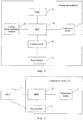
- FIG. 1 is a schematic diagram of a fingerprint module according to an embodiment of the present application, and the fingerprint module is connected to a main control unit.
- a fingerprint module 22 includes a fingerprint sensor 11, a match on chip (Match On Chip, MOC) 12 and a key member 13, and the key member 13 is connected to the fingerprint sensor 11.
- the fingerprint sensor 11 is configured to collect fingerprint information of a verification target and output the fingerprint information to the MOC 12.
- the MOC 12 is configured to authenticate the fingerprint information and output an authentication result to the main control unit.
- the key member 13 is configured to generate an interrupt signal according to a touch operation of a user on the key member 13, to wake up the main control unit.
- the main control unit does not receive information, for example, the authentication result sent by the MOC 12, within a preset period of time, the main control unit enters a sleep state.
- the key member 13 acquires a touch operation of a user, the key member 13 generates an interrupt signal, which is used to wake up the main control unit, so that the main control unit enters a working state.
- the main control unit may have a GPIO interface, and the key member 13 may transmit the interrupt signal to the main control unit through the GPIO interface.
- the main control unit When the main control unit is woken up, in this case, if the MOC 12 and/or fingerprint sensor 11 is in a power-off state, the main control unit sends a first control instruction to the MOC and/or fingerprint sensor to cause the MOC 12 and /or the fingerprint sensor 11 to enter a power-up state according to the first control instruction.
- the MOC 12 is configured to control the key member 13 to be in the power-down state, when the MOC 12 is in the power-up state. Specifically, when the MOC 12 is in the power-up state, the MOC 12 can perform a fingerprint identification process. In this case, the key member 13 does not need to work. In order to save the power consumption of the smart lock, the MOC 12 can control the key member 13 to be in a power-down state.
- the main control unit may be a micro controller unit (Micro Controller Unit, MCU).
- MCU Micro Controller Unit
- the main control unit has a universal asynchronous receiver transmitter (Universal Asynchronous Receiver Transmitter, UART) interface, and communicates with the MOC 12 through the UART interface.
- UART Universal Asynchronous Receiver Transmitter
- LDO Low Dropout Regulator
- GPIO General Purpose Input Output
- the MOC 12 and the fingerprint sensor 11 are connected through a serial peripheral interface (Serial Peripheral Interface, SPI) interface, and the MOC 12 and the fingerprint sensor 11 can communicate through the SPI interface.
- SPI Serial Peripheral Interface
- FIG. 2 is a schematic diagram of a fingerprint module according to another embodiment of the present application, where the MOC 12 is connected to the key member 13 through a control switch 14.
- the MOC 12 is connected to the key member 13 through the control switch 14, and the MOC 12 is specifically configured to control the key member 13 to be in a power-down state through the control switch 14, when the MOC 12 is in a power-up state.
- the MOC 12 has a GPIO interface, and the MOC 12 can control a state of the control switch 14 between the MOC 12 and the key member 13 through the GPIO interface.
- the embodiment of the present application provides a fingerprint module, including: a fingerprint sensor, an MOC and a key member.
- the key member is connected to the fingerprint sensor.
- the fingerprint sensor is configured to collect fingerprint information of a verification target, and output the fingerprint information to the MOC.
- the MOC is configured to authenticate the fingerprint information, and output an authentication result to the main control unit.
- the key member is configured to generate an interrupt signal according to a touch operation of a user on the key member, to wake up the main control unit. That is, the MOC can implement a fingerprint identification process, so that power consumption of the main control unit can be reduced.
- the main control unit sends a first control instruction to the MOC and/or the fingerprint sensor, so that the MOC and/or the fingerprint sensor enters a power-up state according to the first control instruction.
- a smart lock including the fingerprint module can perform the fingerprint identification process, etc.
- the MOC is configured to control the key member to be in a power-down state, when the MOC 12 is in the power-up state. Therefore, when the fingerprint module is applied to the smart lock, power consumption of the smart lock can be reduced.
- the main control unit when the main control unit does not receive information, for example, the authentication result sent by the MOC 12, within a preset period of time, the main control unit sends a second control instruction to the MOC 12 and/or the fingerprint sensor 11, so that the MOC 12 and/or the fingerprint sensor 11 enters the power-down state according to the second control instruction.
- the above preset period of time may be set according to an actual condition, for example, the preset period of time is set to 10 minutes, 15 minutes, etc., which is not limited in the present application.
- the MOC 12 when the MOC 12 enters the power-down state, the MOC 12 is further configured to control the key member 13 to be in the power-up state.
- the MOC 12 is connected to the key member 13 through the control switch 14; when the MOC 12 is in the power-down state, the MOC 12 is configured to trigger the control switch 14 to output a low-level signal, where the low-level signal is used to trigger the key member to be in the power-up state.
- the MOC 12 when the MOC 12 is in the power-down state, the MOC 12 is configured to trigger the control switch 14 to output a high-level signal, where the high-level signal is used to trigger the key member to be in the power-up state.
- the MOC 12 is configured to control the key member 13 to be in the power-up state.
- the main control unit may also directly control the key member 13 to be in the power-up state.
- the main control unit is connected to the key member through the control switch.
- the main control unit triggers the control switch to output a low-level signal, where the low-level signal is used to trigger the key member to be in the power-up state.
- the main control unit when the main control unit is in the sleep state, the main control unit triggers the control switch to output a high-level signal; where the high-level signal is used to trigger the key member to be in the power-up state.
- the embodiment of the present application provides a fingerprint module, including: a fingerprint sensor, an MOC and a key member, and the key member is connected to the fingerprint sensor.
- the main control unit does not receive information within a preset period of time, the main control unit sends a second control instruction to the MOC and/or fingerprint sensor, so that the MOC and/or the fingerprint sensor enters the power-down state according to the second control instruction.
- the fingerprint module is applied to the smart lock, power consumption of the smart lock can be reduced.
- the MOC enters the power-down state
- the MOC is further configured to control the key member to be in the power-up state, thereby ensuring that the smart lock can obtain an operation of a user at any time.
- the fingerprint module further includes: a flash (FLASH) and/or a living body detection module.
- a flash FLASH
- FIG. 3 is a schematic diagram of a fingerprint module according to still another embodiment of the present application.
- the fingerprint module includes: a flash 15 and a living body detection module 16, where the flash 15 includes at least one fingerprint template; and correspondingly, the MOC 12 is specifically configured to match the fingerprint information with the at least one fingerprint template, and output an authentication result to the main control unit.
- the authentication result is a result of successful authentication or a result of failed authentication.
- the living body detection module is configured to detect at least one living body index of the verification target, and output the at least one living body index to the MOC.
- the MOC is further configured to determine whether the verification target is a living body according to the at least one living body index.
- the living body index includes at least one of: blood oxygen or heart rate. For example: when determining that a heart rate of the verification target is within a preset range, the MOC determines the verification target is a living body.
- the MOC When the fingerprint information is successfully authenticated and the verification target is the living body, the MOC may output an authentication result of successful authentication to the main control unit. Conversely, when the fingerprint information fails to be authenticated or the verification target is not the living body, the MOC may output an authentication result of failed authentication to the main control unit.
- the main control unit after the main control unit is woken up, if at least one of the MOC 12, the fingerprint sensor 11, the flash 15 and the living body detection module 16 is in the power-off state, the main control unit will send a first control instruction to at least one of the MOC 12, the fingerprint sensor 11, the flash 15 and the living body detection module 16, so that the at least one of the MOC 12, the fingerprint sensor 11, the flash 15 and the living body detection module 16 will enter the power-up state according to the first control instruction.
- the main control unit may send a second control instruction at least one of the MOC 12, the fingerprint sensor 11, the flash 15 and the living body detection module 16, so that at least one of the MOC 12, the fingerprint sensor 11, the flash 15 and the living body detection module 16 enters the power-down state according to the second control instruction.
- the embodiment of the present application provides a fingerprint module, which includes a fingerprint sensor, an MOC, a key member, a FLASH and a living body detection module.
- the main control unit may send a first control instruction to at least one of the MOC, the fingerprint sensor, the flash and the living body detection module, so that at least one of the MOC, the fingerprint sensor, the flash and the living body detection module will enter the power-up state according to the first control instruction.
- a smart lock including the fingerprint module can perform a fingerprint identification process, etc.
- the MOC is configured to control the key member to be in a power-down state, when the MOC is in the power-up state, which can further reduce power consumption of the smart lock.
- the main control unit When the main control unit does not receive information within a preset period of time, the main control unit will send a second control instruction to at least one of the MOC, the fingerprint sensor, the flash and the living body detection module, so that at least one of the MOC, the fingerprint sensor, the flash and the living body detection module enters the power-down state according to the second control instruction.
- the fingerprint module is applied to the smart lock, power consumption of the smart lock can be reduced.
- the MOC when the MOC enters the power-down state, the MOC is further configured to control the key member to be in the power-up state, thereby ensuring that the smart lock can obtain an operation of a user at any time.
- FIG. 4 is a schematic diagram of a fingerprint identification system according to an embodiment of the present application, where the fingerprint identification system may be applied to but not limited to a smart lock.
- the fingerprint identification system includes: a main control unit 21 and a fingerprint module 22.
- the fingerprint module 22 includes a fingerprint sensor 11, a MOC 12 and a key member 13, and the key member 13 is connected to the fingerprint sensor 11.
- the fingerprint sensor 11 is configured to collect fingerprint information of a verification target and output the fingerprint information to the MOC 12.
- the MOC 12 is configured to authenticate the fingerprint information and output an authentication result to the main control unit 21.
- the key member 13 is configured to generate an interrupt signal according to a touch operation of a user on the key member 13, to wake up the main control unit 21.
- the main control unit 21 does not receive information, for example, the authentication result sent by the MOC 12, within a preset period of time, the main control unit 21 enters a sleep state.
- the key member 13 acquires the touch operation of a user, the key member 13 generates an interrupt signal, and the interrupt signal is used to wake up the main control unit 21 so that the main control unit 21 enters a working state.
- the main control unit 21 may have a GPIO interface, and the key member 13 may transmit the interrupt signal to the main control unit 21 through the GPIO interface.
- the main control unit 21 When the main control unit 21 is woken up, in this case, if the MOC 12 and/or fingerprint sensor 11 is in a power-off state, the main control unit 21 sends a first control instruction to the MOC and/or fingerprint sensor, so that the MOC 12 and /or the fingerprint sensor 11 enters a power-up state according to the first control instruction.
- the MOC 12 is configured to control the key member 13 to be in the power-down state, when the MOC 12 is in the power-up state. Specifically, when the MOC 12 is in the power-up state, the MOC 12 can perform a fingerprint identification process. In this case, the key member 13 does not need to work. In order to save the power consumption of the smart lock, the MOC 12 can control the key member 13 to be in a power-down state.
- the main control unit 21 may be a MCU.
- the main control unit 21 has a UART interface, and communicates with the MOC 12 through the UART interface.
- the main control unit 21 has a GPIO interface, and controls a state of the LDO switch through the GPIO interface.
- the MOC 12 and the fingerprint sensor 11 are connected through an SPI interface, and the MOC 12 and the fingerprint sensor 11 can communicate through the SPI interface.
- FIG. 5 is a schematic diagram of an indication identification system according to another embodiment of the present application, where the MOC 12 is connected to the key member 13 through a control switch 14 as shown in FIG. 5 .
- the MOC 12 is connected to the key member 13 through the control switch 14.
- the MOC 12 is specifically configured to control the key member 13 to be in a power-down state through the control switch 14, when the MOC is in a power-up state.
- the MOC 12 has a GPIO interface, and the MOC 12 can control a state of the control switch 14 between the MOC 12 and the key member 13 through the GPIO interface.
- the embodiment of the present application provides a fingerprint identification system, where the fingerprint identification system includes the fingerprint module described in the above embodiments, and reference can be made to the embodiments of the fingerprint module for effects of the fingerprint identification system, which will not be repeated here.
- the main control unit when the main control unit does not receive information, for example, the authentication result sent by the MOC 12, within a preset period of time, the main control unit sends a second control instruction to the MOC 12 and/or the fingerprint sensor 11, so that the MOC 12 and/or the fingerprint sensor 11 enters the power-down state according to the second control instruction.
- the above preset period of time can be set according to an actual condition, for example, the preset period is set to 10 minutes, 15 minutes, etc., which is not limited in the present application.
- the MOC 12 when the MOC 12 enters the power-down state, the MOC 12 is further configured to control the key member 13 to be in the power-up state.
- the MOC 12 is connected to the key member 13 through the control switch 14, and when the MOC 12 is in the power-down state, the MOC 12 is configured to trigger the control switch 14 to output a low-level signal, where the low-level signal is used to trigger the key member to be in the power-up state.
- the MOC 12 when the MOC 12 is in the power-down state, the MOC 12 is configured to trigger the control switch 14 to output a high-level signal; where the high-level signal is used to trigger the key member to be in the power-up state.
- the MOC 12 is configured to control the key member 13 to be in the power-up state.
- the main control unit may also directly control the key member 13 to be in the power-up state.
- the main control unit is connected to the key member through the control switch, and when the main control unit is in the sleep state, the main control unit triggers the control switch to output a low-level signal, where the low-level signal is used to trigger the key member to be in the power-up state.
- the main control unit when the main control unit is in the sleep state, the main control unit triggers the control switch to output a high-level signal, where the high-level signal is used to trigger the key member to be in the power-up state.
- the embodiment of the present application provides a fingerprint identification system, where the fingerprint identification system includes the fingerprint module described in the above embodiments, and reference can be made to the embodiments of the fingerprint module for effects of the fingerprint identification system, which will not be repeated here.
- the fingerprint module further includes: a flash and/or a living body detection module.
- a flash and/or a living body detection module The following is a detailed description of the fingerprint module including a flash and/or a living body detection module.
- FIG. 6 is a schematic diagram of an indication identification system according to still another embodiment of the present application.
- the fingerprint module in the system further includes: a flash 15 and a living body detection module 16.
- the flash 15 includes at least one fingerprint template, and correspondingly, the MOC 12 is specifically configured to match the fingerprint information with the at least one fingerprint template, and output an authentication result to the main control unit.
- the authentication result is a result of successful authentication or a result of failed authentication.
- the living body detection module 16 is configured to detect at least one living body index of the verification target, and output the at least one living body index to the MOC 12.
- the MOC 12 is further configured to determine whether the verification target is a living body according to the at least one living body index.
- the living body index includes at least one of: blood oxygen or heart rate. For example: when determining that a heart rate of the verification target is within a preset range, the MOC 12 determines the verification target is a living body.
- the MOC 12 may output an authentication result of successful authentication to the main control unit 21. Conversely, when the fingerprint information fails to be authenticated or the verification target is not the living body, the MOC 12 may output an authentication result of failed authentication to the main control unit.
- the main control unit 21 after the main control unit 21 is woken up, in this case, if at least one of the MOC 12, the fingerprint sensor 11, the flash 15 and the living body detection module 16 is in the power-off state, the main control unit 21 will send a first control instruction to at least one of the MOC 12, the fingerprint sensor 11, the flash 15 and the living body detection module 16, so that at least one of the MOC 12, the fingerprint sensor 11, the flash 15 and the living body detection module 16 will enter the power-up state according to the first control instruction.
- the main control unit 21 may send a second control instruction to at least one of the MOC 12, the fingerprint sensor 11, the flash 15 and the living body detection module 16, so that at least one of the MOC 12, the fingerprint sensor 11, the flash 15 and the living body detection module 16 enters the power-down state according to the second control instruction.
- the embodiment of the present application provides a fingerprint identification system, where the fingerprint identification system includes the fingerprint module described in the above embodiments, and reference can be made to the embodiments of the fingerprint module for effects of the fingerprint identification system, which will not be repeated here.
- FIG. 7 is a flowchart of a control method based on a fingerprint identification system according to an embodiment of the present application.
- the fingerprint identification system includes: a main control unit and a fingerprint module.
- the fingerprint module includes: a fingerprint sensor, a match on chip (MOC) and a key member.
- the key member is connected to the fingerprint sensor.
- the method includes the following process:
- step S702 includes: the main control unit sends a first control instruction to the MOC and/or the fingerprint sensor, so that the MOC and/or the fingerprint sensor enters a power-up state according to the first control instruction.
- the method further includes: the MOC controls the key member to be in a power-down state, when the MOC is in a power-up state.
- the MOC is connected to the key member through a control switch; and the MOC controlling, the key member to be in a power-down state includes: the MOC controls the key member to be in the power-down state through the control switch, when the MOC is in the power-up state.
- the method may be executed by the above fingerprint identification system, and for contents and effects thereof, reference may be made to the embodiments of the above fingerprint identification system, which will not be repeated here.
- FIG. 8 is a flowchart of a control method based on a fingerprint identification system according to another embodiment of the present application.
- the fingerprint identification system includes: a main control unit and a fingerprint module.
- the fingerprint module includes: a fingerprint sensor, an MOC and a key member.
- the key member is connected to the fingerprint sensor.
- the method includes the following process:
- Step S801 The main control unit sends a second control instruction to the MOC and/or the fingerprint sensor when the main control unit does not receive information within a preset period of time.
- Step S802 The MOC and/or the fingerprint sensor enters a power-down state according to the second control instruction.
- the method when the MOC is in the power-down state, the method further includes: the MOC controls the key member to be in a power-up state.
- the MOC is connected to the key member through a control switch, and the MOC controlling the key member to be in a power-up state includes: the MOC triggers the control switch to output a low-level signal when the MOC is in the power-down state, where the low-level signal is used to trigger the key member to be in the power-up state.
- the fingerprint module further includes: a flash; the flash includes at least one fingerprint template; the MOC authenticating the fingerprint information and outputting the authentication result to the main control unit includes: the MOC matches the fingerprint information with the at least one fingerprint template, and outputs the authentication result.
- the authentication result is a result of successful authentication or a result of failed authentication.
- the fingerprint module further includes a living body detection module; and correspondingly, the method further includes: the living body detection module detects at least one living body index of the verification target, and outputs the at least one living body index to the MOC; and the MOC determines whether the verification target is a living body according to the at least one living body index.
- the MOC outputs an authentication result of successful authentication when the fingerprint information is successfully authenticated and the verification target is a living body.
- the living body index includes at least one of: blood oxygen or heart rate.
- the method may be performed by the above fingerprint identification system, and for contents and effects thereof, reference may be made to the embodiments of the above fingerprint identification system, which will not be repeated here.
- the present application further provides a smart lock, including: the above fingerprint identification system.
- a smart lock including: the above fingerprint identification system.
- an unlocking method of the smart lock may include a fingerprint password recognition method.
- the smart lock may further include at least one unlocking method as follows: an unlocking method based on NFC, a digital password unlocking method, and the like.
- the foregoing program may be stored in a computer readable storage medium.
- the foregoing storage medium may include a ROM, a RAM, a magnetic disk, or an optical disk and other media that can store program codes.
Landscapes
- Engineering & Computer Science (AREA)
- Physics & Mathematics (AREA)
- Theoretical Computer Science (AREA)
- General Physics & Mathematics (AREA)
- General Engineering & Computer Science (AREA)
- Health & Medical Sciences (AREA)
- Human Computer Interaction (AREA)
- Computer Security & Cryptography (AREA)
- Life Sciences & Earth Sciences (AREA)
- Computer Hardware Design (AREA)
- Multimedia (AREA)
- Software Systems (AREA)
- Surgery (AREA)
- Pathology (AREA)
- General Health & Medical Sciences (AREA)
- Biophysics (AREA)
- Heart & Thoracic Surgery (AREA)
- Biomedical Technology (AREA)
- Veterinary Medicine (AREA)
- Molecular Biology (AREA)
- Animal Behavior & Ethology (AREA)
- Medical Informatics (AREA)
- Public Health (AREA)
- Cardiology (AREA)
- Physiology (AREA)
- Optics & Photonics (AREA)
- Computing Systems (AREA)
- Manufacturing & Machinery (AREA)
- Collating Specific Patterns (AREA)
- Image Input (AREA)
- Measurement Of The Respiration, Hearing Ability, Form, And Blood Characteristics Of Living Organisms (AREA)
Abstract
Description
- The present application relates to the field of fingerprint identification technologies, and in particular, to a fingerprint module, a fingerprint identification system, a control method and a smart lock.
- Smart locks are ubiquitous in people's lives, which can be unlocked in various ways, such as an unlocking method based on Near Field Communication (NFC), a digital password unlocking method, a fingerprint password unlocking method, etc. A smart lock can involve one or more unlocking methods.
- At present, a smart lock with fingerprint identification function includes: a main control unit, a fingerprint sensor and a flash (FLASH). A fingerprint identification process of the smart lock is: the fingerprint sensor collects a fingerprint image and sends the fingerprint image to the main control unit, the main control unit matches the acquired fingerprint image with a fingerprint template in the flash to obtain a matching result, and when matching is successful, the main control unit in the smart lock controls an actuator to drive the smart lock to be in an open state.
- In the prior art, the fingerprint identification process is mainly implemented by the main control unit, which will cause a problem of excessive power consumption of the main control unit.
- The present application provides a fingerprint module, a fingerprint identification system, a control method and a smart lock, so that power consumption of the smart lock can be reduced.
- In a first aspect, the present application provides a fingerprint module connected to a main control unit, the fingerprint module includes: a fingerprint sensor, a match on chip (MOC), and a key member, and the key member is connected to the fingerprint sensor. The fingerprint sensor is configured to collect fingerprint information of a verification target, and output the fingerprint information to the MOC. The MOC is configured to authenticate the fingerprint information, and output an authentication result to the main control unit. The key member is configured to generate an interrupt signal according to a touch operation of a user on the key member, to wake up the main control unit.
- In a possible design, the MOC and/or the fingerprint sensor is further configured to receive a first control instruction sent by the main control unit, and enter a power-up state according to the first control instruction.
- In a possible design, the MOC is further configured to control the key member to be in a power-down state.
- In a possible design, the MOC is connected to the key member through a control switch. The MOC is specifically configured to control the key member to be in the power-down state through the control switch when the MOC is in the power-up state.
- In a possible design, the MOC and/or the fingerprint sensor is further configured to receive a second control instruction sent by the main control unit, and enter a power-down state according to the second control instruction.
- In a possible design, the MOC is further configured to control the key member to be in a power-up state.
- In a possible design, the MOC is connected to the key member through a control switch. The MOC is configured to trigger the control switch to output a low-level signal, when the MOC is in the power-down state, where the low-level signal is used to trigger the key member to be in the power-up state.
- In a possible design, the fingerprint module further includes: a flash. The flash includes at least one fingerprint template. The MOC is specifically configured to match the fingerprint information with the at least one fingerprint template, and output an authentication result.
- In a possible design, the authentication result is a result of successful authentication or a result of failed authentication.
- In a possible design, the fingerprint module further includes a living body detection module. The living body detection module is configured to detect at least one living body index of the verification target, and output the at least one living body index to the MOC. The MOC is further configured to determine whether the verification target is a living body according to the at least one living body index.
- In a possible design, the MOC is configured to output an authentication result of successful authentication when the fingerprint information is successfully authenticated and the verification target is the living body.
- In a possible design, the living body index includes at least one of: blood oxygen or heart rate.
- In a second aspect, the present application provides a fingerprint identification system, including: a main control unit and the fingerprint module as described in the first aspect or optional manners of the first aspect.
- In a possible design, the main control unit is specifically configured to: send a second control instruction to the MOC and/or the fingerprint sensor when the main control unit does not receive information within a preset period of time, and the second control instruction is configured to control the MOC and/or the fingerprint sensor to enter a power-down state.
- In a third aspect, the present application provides a control method based on a fingerprint identification system, the fingerprint identification system includes: a main control unit and a fingerprint module, and the fingerprint module includes: a fingerprint sensor, a match on chip (MOC) and a key member, the key member is connected to the fingerprint sensor. Correspondingly, the method includes: the key member generates an interrupt signal according to a touch operation of a user on the key member, to wake up the main control unit, the main control unit controls the fingerprint sensor and/or the MOC to power up, the fingerprint sensor collects fingerprint information of a verification target, and outputs the fingerprint information to the MOC, and the MOC authenticates the fingerprint information and outputs an authentication result to the main control unit.
- In a fourth aspect, the present application provides a smart lock, including: the fingerprint identification system as described in the third aspect or optional manners of the third aspect.
- The present application provides a fingerprint module, a fingerprint identification system, a control method and a smart lock, including: a fingerprint sensor, an MOC and a key member, and the key member is connected to the fingerprint sensor. The key member is configured to generate an interrupt signal according to a touch operation of a user on the key member, to wake up the main control unit. That is, the MOC can implement a fingerprint identification process, and thus power consumption of the main control unit can be reduced. When the MOC and/or the fingerprint sensor is in a power-off state, the main control unit sends a first control instruction to the MOC and/or the fingerprint sensor, so that the MOC and/or the fingerprint sensor enters a power-up state according to the first control instruction. Based on this, a smart lock including the fingerprint module can perform a fingerprint identification process, etc. Optionally, the MOC is configured to control the key member to be in a power-down state, when the MOC is in the power-up state, which can further reduce power consumption of the smart lock. When the main control unit does not receive information within a preset period of time, the main control unit sends a second control instruction to the MOC and/or fingerprint sensor, so that the MOC and/or the fingerprint sensor enters the power-down state according to the second control instruction. When the fingerprint module is applied to the smart lock, power consumption of the smart lock can thus be reduced. Optionally, when the MOC enters the power-down state, the MOC is further configured to control the key member to be in the power-up state, thereby ensuring that the smart lock can obtain the operation of a user at any time.
- In order to describe the technical solutions in embodiments of the present application or in the prior art more clearly, the following briefly introduces the accompanying drawings needed for describing the embodiments or the prior art. Apparently, the accompanying drawings in the following description are merely some embodiments of the present application, and persons of ordinary skill in the art may still derive other accompanying drawings from these accompanying drawings without creative effort.
-
FIG. 1 is a schematic diagram of a fingerprint module according to an embodiment of the present application; -
FIG. 2 is a schematic diagram of a fingerprint module according to another embodiment of the present application; -
FIG. 3 is a schematic diagram of a fingerprint module according to a still another embodiment of the present application; -
FIG. 4 is a schematic diagram of a fingerprint identification system according to an embodiment of the present application; -
FIG. 5 is a schematic diagram of an indication identification system according to another embodiment of the present application; -
FIG. 6 is a schematic diagram of an indication identification system according to still another embodiment of the present application; -
FIG. 7 is a flowchart of a control method based on a fingerprint identification system according to an embodiment of the present application; and -
FIG. 8 is a flowchart of a control method based on a fingerprint identification system according to another embodiment of the present application. - In order to make the purposes, technical solutions and advantages in embodiments of the present application more clearly, the technical solutions in the embodiments of the present application will be described clearly and completely below in combination with accompanying drawings in the embodiments of the present application. Apparently, the described accompanying drawings in the following description are merely some embodiments of the present application, rather than all of them. All other embodiments obtained by those skilled in the art without paying creative effort shall fall within the scope of protection of the present application.
- The terms "first", "second", "third", "fourth" and/or the like (if any) in the description, claims and the drawings of the present application are used to distinguish similar objects, and are not necessarily used to describe specific order or sequence. It should be understood that the numerals used as such are interchangeable under appropriate circumstances, so that the embodiments described herein, for example, can be implemented in alternative order other than those illustrated or described herein. In addition, the terms "include" and "have" and any variations thereof are intended to cover non-exclusive inclusion. For example, a process, a method, a system, a product or an apparatus that includes a series of steps or units do not have to be limited to those steps or units expressly listed, but may instead include other steps or units not expressly listed, or steps or units inherent to the process, method, product or apparatus.
- As mentioned above, in the prior art, the fingerprint identification process is implemented by a main control unit, which will cause a problem of excessive power consumption of the main control unit. In order to solve this technical problem, the present application provides a fingerprint module, a fingerprint identification system, a control method and a smart lock.
-
FIG. 1 is a schematic diagram of a fingerprint module according to an embodiment of the present application, and the fingerprint module is connected to a main control unit. As shown inFIG. 1 , afingerprint module 22 includes afingerprint sensor 11, a match on chip (Match On Chip, MOC) 12 and akey member 13, and thekey member 13 is connected to thefingerprint sensor 11. Thefingerprint sensor 11 is configured to collect fingerprint information of a verification target and output the fingerprint information to theMOC 12. TheMOC 12 is configured to authenticate the fingerprint information and output an authentication result to the main control unit. - The
key member 13 is configured to generate an interrupt signal according to a touch operation of a user on thekey member 13, to wake up the main control unit. When the main control unit does not receive information, for example, the authentication result sent by theMOC 12, within a preset period of time, the main control unit enters a sleep state. When the above fingerprint module is applied to a smart lock, power consumption of the smart lock can be reduced in this way. When thekey member 13 acquires a touch operation of a user, thekey member 13 generates an interrupt signal, which is used to wake up the main control unit, so that the main control unit enters a working state. - In a possible design, the main control unit may have a GPIO interface, and the
key member 13 may transmit the interrupt signal to the main control unit through the GPIO interface. - When the main control unit is woken up, in this case, if the
MOC 12 and/orfingerprint sensor 11 is in a power-off state, the main control unit sends a first control instruction to the MOC and/or fingerprint sensor to cause theMOC 12 and /or thefingerprint sensor 11 to enter a power-up state according to the first control instruction. - In a possible design, the
MOC 12 is configured to control thekey member 13 to be in the power-down state, when theMOC 12 is in the power-up state. Specifically, when theMOC 12 is in the power-up state, theMOC 12 can perform a fingerprint identification process. In this case, thekey member 13 does not need to work. In order to save the power consumption of the smart lock, theMOC 12 can control thekey member 13 to be in a power-down state. - In a possible design, the main control unit may be a micro controller unit (Micro Controller Unit, MCU).
- In a possible design, the main control unit has a universal asynchronous receiver transmitter (Universal Asynchronous Receiver Transmitter, UART) interface, and communicates with the
MOC 12 through the UART interface. - In a possible design, there is a low dropout regulator (Low Dropout Regulator, LDO) switch connected between the main control unit and the fingerprint module, and the main control unit has a general purpose input output (General Purpose Input Output, GPIO) interface, and controls a state of the LDO switch through the GPIO interface.
- In a possible design, the
MOC 12 and thefingerprint sensor 11 are connected through a serial peripheral interface (Serial Peripheral Interface, SPI) interface, and theMOC 12 and thefingerprint sensor 11 can communicate through the SPI interface. - In a possible design, the
key member 13 may be a ring key, which surrounds thefingerprint sensor 11. In a possible design,FIG. 2 is a schematic diagram of a fingerprint module according to another embodiment of the present application, where theMOC 12 is connected to thekey member 13 through acontrol switch 14. - In a possible design, the
MOC 12 is connected to thekey member 13 through thecontrol switch 14, and theMOC 12 is specifically configured to control thekey member 13 to be in a power-down state through thecontrol switch 14, when theMOC 12 is in a power-up state. - In a possible design, the
MOC 12 has a GPIO interface, and theMOC 12 can control a state of thecontrol switch 14 between theMOC 12 and thekey member 13 through the GPIO interface. - The embodiment of the present application provides a fingerprint module, including: a fingerprint sensor, an MOC and a key member. The key member is connected to the fingerprint sensor. The fingerprint sensor is configured to collect fingerprint information of a verification target, and output the fingerprint information to the MOC. The MOC is configured to authenticate the fingerprint information, and output an authentication result to the main control unit. The key member is configured to generate an interrupt signal according to a touch operation of a user on the key member, to wake up the main control unit. That is, the MOC can implement a fingerprint identification process, so that power consumption of the main control unit can be reduced. Optionally, when the MOC and/or the fingerprint sensor is in a power-off state, the main control unit sends a first control instruction to the MOC and/or the fingerprint sensor, so that the MOC and/or the fingerprint sensor enters a power-up state according to the first control instruction. Based on this, a smart lock including the fingerprint module can perform the fingerprint identification process, etc. Optionally, the MOC is configured to control the key member to be in a power-down state, when the
MOC 12 is in the power-up state. Therefore, when the fingerprint module is applied to the smart lock, power consumption of the smart lock can be reduced. - On the basis of the previous embodiment, further, when the main control unit does not receive information, for example, the authentication result sent by the
MOC 12, within a preset period of time, the main control unit sends a second control instruction to theMOC 12 and/or thefingerprint sensor 11, so that theMOC 12 and/or thefingerprint sensor 11 enters the power-down state according to the second control instruction. The above preset period of time may be set according to an actual condition, for example, the preset period of time is set to 10 minutes, 15 minutes, etc., which is not limited in the present application. - In a possible design, when the
MOC 12 enters the power-down state, theMOC 12 is further configured to control thekey member 13 to be in the power-up state. - In a possible design, the
MOC 12 is connected to thekey member 13 through thecontrol switch 14; when theMOC 12 is in the power-down state, theMOC 12 is configured to trigger thecontrol switch 14 to output a low-level signal, where the low-level signal is used to trigger the key member to be in the power-up state. - Or, in another possible design, when the
MOC 12 is in the power-down state, theMOC 12 is configured to trigger thecontrol switch 14 to output a high-level signal, where the high-level signal is used to trigger the key member to be in the power-up state. - In the above solution, the
MOC 12 is configured to control thekey member 13 to be in the power-up state. Actually, the main control unit may also directly control thekey member 13 to be in the power-up state. - In a possible design, the main control unit is connected to the key member through the control switch. When the main control unit is in the sleep state, the main control unit triggers the control switch to output a low-level signal, where the low-level signal is used to trigger the key member to be in the power-up state.
- Or, in another possible design, when the main control unit is in the sleep state, the main control unit triggers the control switch to output a high-level signal; where the high-level signal is used to trigger the key member to be in the power-up state.
- The embodiment of the present application provides a fingerprint module, including: a fingerprint sensor, an MOC and a key member, and the key member is connected to the fingerprint sensor. When the main control unit does not receive information within a preset period of time, the main control unit sends a second control instruction to the MOC and/or fingerprint sensor, so that the MOC and/or the fingerprint sensor enters the power-down state according to the second control instruction. When the fingerprint module is applied to the smart lock, power consumption of the smart lock can be reduced. Optionally, when the MOC enters the power-down state, the MOC is further configured to control the key member to be in the power-up state, thereby ensuring that the smart lock can obtain an operation of a user at any time.
- On the basis of any of the previous embodiments, further, the fingerprint module further includes: a flash (FLASH) and/or a living body detection module. The following is a detailed description of the fingerprint module including a flash and a living body detection module.
FIG. 3 is a schematic diagram of a fingerprint module according to still another embodiment of the present application. As shown inFIG. 3 , the fingerprint module includes: aflash 15 and a livingbody detection module 16, where theflash 15 includes at least one fingerprint template; and correspondingly, theMOC 12 is specifically configured to match the fingerprint information with the at least one fingerprint template, and output an authentication result to the main control unit. The authentication result is a result of successful authentication or a result of failed authentication. - In a possible design, the living body detection module is configured to detect at least one living body index of the verification target, and output the at least one living body index to the MOC. The MOC is further configured to determine whether the verification target is a living body according to the at least one living body index. The living body index includes at least one of: blood oxygen or heart rate. For example: when determining that a heart rate of the verification target is within a preset range, the MOC determines the verification target is a living body.
- When the fingerprint information is successfully authenticated and the verification target is the living body, the MOC may output an authentication result of successful authentication to the main control unit. Conversely, when the fingerprint information fails to be authenticated or the verification target is not the living body, the MOC may output an authentication result of failed authentication to the main control unit.
- In a possible design, after the main control unit is woken up, if at least one of the
MOC 12, thefingerprint sensor 11, theflash 15 and the livingbody detection module 16 is in the power-off state, the main control unit will send a first control instruction to at least one of theMOC 12, thefingerprint sensor 11, theflash 15 and the livingbody detection module 16, so that the at least one of theMOC 12, thefingerprint sensor 11, theflash 15 and the livingbody detection module 16 will enter the power-up state according to the first control instruction. - When the main control unit does not receive information, for example, the authentication result sent by the
MOC 12, within a preset period of time, and at least one of theMOC 12, thefingerprint sensor 11, theflash 15 and the livingbody detection module 16 is in the power-up state, the main control unit may send a second control instruction at least one of theMOC 12, thefingerprint sensor 11, theflash 15 and the livingbody detection module 16, so that at least one of theMOC 12, thefingerprint sensor 11, theflash 15 and the livingbody detection module 16 enters the power-down state according to the second control instruction. - The embodiment of the present application provides a fingerprint module, which includes a fingerprint sensor, an MOC, a key member, a FLASH and a living body detection module. After the main control unit is woken up, the main control unit may send a first control instruction to at least one of the MOC, the fingerprint sensor, the flash and the living body detection module, so that at least one of the MOC, the fingerprint sensor, the flash and the living body detection module will enter the power-up state according to the first control instruction. Based on this, a smart lock including the fingerprint module can perform a fingerprint identification process, etc. Optionally, the MOC is configured to control the key member to be in a power-down state, when the MOC is in the power-up state, which can further reduce power consumption of the smart lock. When the main control unit does not receive information within a preset period of time, the main control unit will send a second control instruction to at least one of the MOC, the fingerprint sensor, the flash and the living body detection module, so that at least one of the MOC, the fingerprint sensor, the flash and the living body detection module enters the power-down state according to the second control instruction. When the fingerprint module is applied to the smart lock, power consumption of the smart lock can be reduced. Optionally, when the MOC enters the power-down state, the MOC is further configured to control the key member to be in the power-up state, thereby ensuring that the smart lock can obtain an operation of a user at any time.
-
FIG. 4 is a schematic diagram of a fingerprint identification system according to an embodiment of the present application, where the fingerprint identification system may be applied to but not limited to a smart lock. As shown inFIG. 4 , the fingerprint identification system includes: amain control unit 21 and afingerprint module 22. Thefingerprint module 22 includes afingerprint sensor 11, aMOC 12 and akey member 13, and thekey member 13 is connected to thefingerprint sensor 11. Thefingerprint sensor 11 is configured to collect fingerprint information of a verification target and output the fingerprint information to theMOC 12. TheMOC 12 is configured to authenticate the fingerprint information and output an authentication result to themain control unit 21. - The
key member 13 is configured to generate an interrupt signal according to a touch operation of a user on thekey member 13, to wake up themain control unit 21. When themain control unit 21 does not receive information, for example, the authentication result sent by theMOC 12, within a preset period of time, themain control unit 21 enters a sleep state. When the above fingerprint module is applied to a smart lock, power consumption of the smart lock can be reduced in this way. However, when thekey member 13 acquires the touch operation of a user, thekey member 13 generates an interrupt signal, and the interrupt signal is used to wake up themain control unit 21 so that themain control unit 21 enters a working state. - In a possible design, the
main control unit 21 may have a GPIO interface, and thekey member 13 may transmit the interrupt signal to themain control unit 21 through the GPIO interface. - When the
main control unit 21 is woken up, in this case, if theMOC 12 and/orfingerprint sensor 11 is in a power-off state, themain control unit 21 sends a first control instruction to the MOC and/or fingerprint sensor, so that theMOC 12 and /or thefingerprint sensor 11 enters a power-up state according to the first control instruction. - In a possible design, the
MOC 12 is configured to control thekey member 13 to be in the power-down state, when theMOC 12 is in the power-up state. Specifically, when theMOC 12 is in the power-up state, theMOC 12 can perform a fingerprint identification process. In this case, thekey member 13 does not need to work. In order to save the power consumption of the smart lock, theMOC 12 can control thekey member 13 to be in a power-down state. - In a possible design, the
main control unit 21 may be a MCU. - In a possible design, the
main control unit 21 has a UART interface, and communicates with theMOC 12 through the UART interface. - In a possible design, there is a LDO switch connected between the
main control unit 21 and the fingerprint module, and themain control unit 21 has a GPIO interface, and controls a state of the LDO switch through the GPIO interface. - In a possible design, the
MOC 12 and thefingerprint sensor 11 are connected through an SPI interface, and theMOC 12 and thefingerprint sensor 11 can communicate through the SPI interface. - In a possible design, the
key member 13 may be a ring key, which surrounds thefingerprint sensor 11. In a possible design,FIG. 5 is a schematic diagram of an indication identification system according to another embodiment of the present application, where theMOC 12 is connected to thekey member 13 through acontrol switch 14 as shown inFIG. 5 . - In a possible design, the
MOC 12 is connected to thekey member 13 through thecontrol switch 14. TheMOC 12 is specifically configured to control thekey member 13 to be in a power-down state through thecontrol switch 14, when the MOC is in a power-up state. - In a possible design, the
MOC 12 has a GPIO interface, and theMOC 12 can control a state of thecontrol switch 14 between theMOC 12 and thekey member 13 through the GPIO interface. - The embodiment of the present application provides a fingerprint identification system, where the fingerprint identification system includes the fingerprint module described in the above embodiments, and reference can be made to the embodiments of the fingerprint module for effects of the fingerprint identification system, which will not be repeated here.
- On the basis of the previous embodiment, further, when the main control unit does not receive information, for example, the authentication result sent by the
MOC 12, within a preset period of time, the main control unit sends a second control instruction to theMOC 12 and/or thefingerprint sensor 11, so that theMOC 12 and/or thefingerprint sensor 11 enters the power-down state according to the second control instruction. The above preset period of time can be set according to an actual condition, for example, the preset period is set to 10 minutes, 15 minutes, etc., which is not limited in the present application. - In a possible design, when the
MOC 12 enters the power-down state, theMOC 12 is further configured to control thekey member 13 to be in the power-up state. - In a possible design, the
MOC 12 is connected to thekey member 13 through thecontrol switch 14, and when theMOC 12 is in the power-down state, theMOC 12 is configured to trigger thecontrol switch 14 to output a low-level signal, where the low-level signal is used to trigger the key member to be in the power-up state. - Or, in another possible design, when the
MOC 12 is in the power-down state, theMOC 12 is configured to trigger thecontrol switch 14 to output a high-level signal; where the high-level signal is used to trigger the key member to be in the power-up state. - In the above solution, the
MOC 12 is configured to control thekey member 13 to be in the power-up state. Actually, the main control unit may also directly control thekey member 13 to be in the power-up state. - In a possible design, the main control unit is connected to the key member through the control switch, and when the main control unit is in the sleep state, the main control unit triggers the control switch to output a low-level signal, where the low-level signal is used to trigger the key member to be in the power-up state.
- Or, in another possible design, when the main control unit is in the sleep state, the main control unit triggers the control switch to output a high-level signal, where the high-level signal is used to trigger the key member to be in the power-up state.
- The embodiment of the present application provides a fingerprint identification system, where the fingerprint identification system includes the fingerprint module described in the above embodiments, and reference can be made to the embodiments of the fingerprint module for effects of the fingerprint identification system, which will not be repeated here.
- On the basis of any of the previous embodiments, further, the fingerprint module further includes: a flash and/or a living body detection module. The following is a detailed description of the fingerprint module including a flash and/or a living body detection module.
FIG. 6 is a schematic diagram of an indication identification system according to still another embodiment of the present application. As shown inFIG. 6 , the fingerprint module in the system further includes: aflash 15 and a livingbody detection module 16. Theflash 15 includes at least one fingerprint template, and correspondingly, theMOC 12 is specifically configured to match the fingerprint information with the at least one fingerprint template, and output an authentication result to the main control unit. The authentication result is a result of successful authentication or a result of failed authentication. - In a possible design, the living
body detection module 16 is configured to detect at least one living body index of the verification target, and output the at least one living body index to theMOC 12. TheMOC 12 is further configured to determine whether the verification target is a living body according to the at least one living body index. The living body index includes at least one of: blood oxygen or heart rate. For example: when determining that a heart rate of the verification target is within a preset range, theMOC 12 determines the verification target is a living body. - When the fingerprint information is successfully authenticated and the verification target is the living body, the
MOC 12 may output an authentication result of successful authentication to themain control unit 21. Conversely, when the fingerprint information fails to be authenticated or the verification target is not the living body, theMOC 12 may output an authentication result of failed authentication to the main control unit. - In a possible design, after the
main control unit 21 is woken up, in this case, if at least one of theMOC 12, thefingerprint sensor 11, theflash 15 and the livingbody detection module 16 is in the power-off state, themain control unit 21 will send a first control instruction to at least one of theMOC 12, thefingerprint sensor 11, theflash 15 and the livingbody detection module 16, so that at least one of theMOC 12, thefingerprint sensor 11, theflash 15 and the livingbody detection module 16 will enter the power-up state according to the first control instruction. - When the
main control unit 21 does not receive information, for example, the authentication result sent by theMOC 12, within a preset period of time, and at least one of theMOC 12, thefingerprint sensor 11, theflash 15 and the livingbody detection module 16 is in the power-up state, themain control unit 21 may send a second control instruction to at least one of theMOC 12, thefingerprint sensor 11, theflash 15 and the livingbody detection module 16, so that at least one of theMOC 12, thefingerprint sensor 11, theflash 15 and the livingbody detection module 16 enters the power-down state according to the second control instruction. - The embodiment of the present application provides a fingerprint identification system, where the fingerprint identification system includes the fingerprint module described in the above embodiments, and reference can be made to the embodiments of the fingerprint module for effects of the fingerprint identification system, which will not be repeated here.
-
FIG. 7 is a flowchart of a control method based on a fingerprint identification system according to an embodiment of the present application. The fingerprint identification system includes: a main control unit and a fingerprint module. The fingerprint module includes: a fingerprint sensor, a match on chip (MOC) and a key member. The key member is connected to the fingerprint sensor. As shown inFIG.7 , the method includes the following process: - Step S701: The key member generates an interrupt signal according to a touch operation of a user on the key member, to wake up the main control unit.
- Step S702: The main control unit controls the fingerprint sensor and/or the MOC to power up.
- Step S703: The fingerprint sensor collects fingerprint information of a verification target, and outputs the fingerprint information to the MOC.
- Step S704: The MOC authenticates the fingerprint information and outputs an authentication result to the main control unit.
- In a possible design, step S702 includes: the main control unit sends a first control instruction to the MOC and/or the fingerprint sensor, so that the MOC and/or the fingerprint sensor enters a power-up state according to the first control instruction.
- In a possible design, the method further includes: the MOC controls the key member to be in a power-down state, when the MOC is in a power-up state.
- In a possible design, the MOC is connected to the key member through a control switch; and the MOC controlling, the key member to be in a power-down state includes: the MOC controls the key member to be in the power-down state through the control switch, when the MOC is in the power-up state.
- The method may be executed by the above fingerprint identification system, and for contents and effects thereof, reference may be made to the embodiments of the above fingerprint identification system, which will not be repeated here.
-
FIG. 8 is a flowchart of a control method based on a fingerprint identification system according to another embodiment of the present application. The fingerprint identification system includes: a main control unit and a fingerprint module. The fingerprint module includes: a fingerprint sensor, an MOC and a key member. The key member is connected to the fingerprint sensor. As shown inFIG.8 , the method includes the following process: - Step S801: The main control unit sends a second control instruction to the MOC and/or the fingerprint sensor when the main control unit does not receive information within a preset period of time.
- Step S802: The MOC and/or the fingerprint sensor enters a power-down state according to the second control instruction.
- In a possible design, when the MOC is in the power-down state, the method further includes: the MOC controls the key member to be in a power-up state.
- In a possible design, the MOC is connected to the key member through a control switch, and the MOC controlling the key member to be in a power-up state includes: the MOC triggers the control switch to output a low-level signal when the MOC is in the power-down state, where the low-level signal is used to trigger the key member to be in the power-up state.
- In a possible design, the fingerprint module further includes: a flash; the flash includes at least one fingerprint template; the MOC authenticating the fingerprint information and outputting the authentication result to the main control unit includes: the MOC matches the fingerprint information with the at least one fingerprint template, and outputs the authentication result.
- In a possible design, the authentication result is a result of successful authentication or a result of failed authentication.
- In a possible design, the fingerprint module further includes a living body detection module; and correspondingly, the method further includes: the living body detection module detects at least one living body index of the verification target, and outputs the at least one living body index to the MOC; and the MOC determines whether the verification target is a living body according to the at least one living body index.
- In a possible design, there further includes: the MOC outputs an authentication result of successful authentication when the fingerprint information is successfully authenticated and the verification target is a living body.
- In a possible design, the living body index includes at least one of: blood oxygen or heart rate.
- The method may be performed by the above fingerprint identification system, and for contents and effects thereof, reference may be made to the embodiments of the above fingerprint identification system, which will not be repeated here.
- The present application further provides a smart lock, including: the above fingerprint identification system. For functions and effects of the system, reference may be made to the above embodiments, which will not be repeated in the present application.
- It should be noted that an unlocking method of the smart lock may include a fingerprint password recognition method. Optionally, the smart lock may further include at least one unlocking method as follows: an unlocking method based on NFC, a digital password unlocking method, and the like.
- Persons of ordinary skill in the art could understand that all or part of the steps in the above method embodiments may be implemented by a program instructing relevant hardware. The foregoing program may be stored in a computer readable storage medium. When the program is executed, the steps including the above method embodiments are executed. The foregoing storage medium may include a ROM, a RAM, a magnetic disk, or an optical disk and other media that can store program codes.
- Finally, it should be noted that the above embodiments are merely used to describe the technical solutions of the present invention other than limiting the present invention. Although the present invention is described in detail with reference to the foregoing embodiments, persons of ordinary skill in the art should understand that they may still make modifications to the technical solutions described in the foregoing embodiments or make equivalent substitutions to all or some technical features thereof. However, these modifications and substitutions do not cause the corresponding technical solutions departing from the technical solutions of the embodiments of the present invention.
Claims (27)
- A fingerprint module, connected to a main control unit, wherein the fingerprint module comprises: a fingerprint sensor, a match on chip MOC and a key member, and the key member is connected to the fingerprint sensor;
the fingerprint sensor is configured to collect fingerprint information of a verification target, and output the fingerprint information to the MOC;
the MOC is configured to authenticate the fingerprint information, and output an authentication result to the main control unit; and
the key member is configured to generate an interrupt signal according to a touch operation of a user on the key member, to wake up the main control unit. - The fingerprint module according to claim 1, wherein:
the MOC and/or the fingerprint sensor is further configured to receive a first control instruction sent by the main control unit, and enter a power-up state according to the first control instruction. - The fingerprint module according to claim 2, wherein:
the MOC is further configured to control the key member to be in a power-down state. - The fingerprint module according to claim 3, wherein the MOC is connected to the key member through a control switch; and
the MOC is specifically configured to control the key member to be in the power-down state through the control switch when the MOC is in the power-up state. - The fingerprint module according to claim 1, wherein:
the MOC and/or the fingerprint sensor is further configured to receive a second control instruction sent by the main control unit, and enter a power-down state according to the second control instruction. - The fingerprint module according to claim 5, wherein:
the MOC is further configured to control the key member to be in a power-up state. - The fingerprint module according to claim 6, wherein the MOC is connected to the key member through a control switch; and
the MOC is configured to trigger the control switch to output a low-level signal, when the MOC is in the power-down state;
wherein the low-level signal is used to trigger the key member to be in the power-up state. - The fingerprint module according to any one of claims 1-7, further comprising: a flash;
the flash comprising at least one fingerprint template;
the MOC being specifically configured to match the fingerprint information with the at least one fingerprint template, and output an authentication result. - The fingerprint module according to claim 8, wherein:
the authentication result is a result of successful authentication or a result of failed authentication. - The fingerprint module according to claim 1, wherein the fingerprint module further comprises a living body detection module;
the living body detection module is configured to detect at least one living body index of the verification target, and output the at least one living body index to the MOC; and
the MOC is further configured to determine whether the verification target is a living body according to the at least one living body index. - The fingerprint module according to claim 10, wherein the MOC is configured to output an authentication result of successful authentication when the fingerprint information is successfully authenticated and the verification target is the living body.
- The fingerprint module according to claim 10 or 11, wherein the living body index comprises at least one of: blood oxygen or heart rate.
- A fingerprint identification system, comprising: a main control unit and the fingerprint module according to any one of claims 1-12.
- The system according to claim 13, wherein:
the main control unit is specifically configured to: send a second control instruction to the MOC and/or the fingerprint sensor when the main control unit does not receive information within a preset period of time, and the second control instruction is configured to control the MOC and/or the fingerprint sensor to enter a power-down state. - A control method based on a fingerprint identification system, wherein the fingerprint identification system comprises: a main control unit and a fingerprint module, and the fingerprint module comprises: a fingerprint sensor, a match on chip MOC and a key member, and the key member is connected to the fingerprint sensor; and correspondingly, the method comprises:generating, by the key member, an interrupt signal according to a touch operation of a user on the key member, to wake up the main control unit;controlling, by the main control unit, the fingerprint sensor and/or the MOC to power up;collecting, by the fingerprint sensor, fingerprint information of a verification target, and outputting the fingerprint information to the MOC; andauthenticating, by the MOC, the fingerprint information and outputting an authentication result to the main control unit.
- The method according to claim 15, wherein the controlling, by the main control unit, the fingerprint sensor and/or the MOC to power up comprises:
sending, by the main control unit, a first control instruction to the MOC and/or the fingerprint sensor, so that the MOC and/or the fingerprint sensor enters a power-up state according to the first control instruction. - The method according to claim 16, further comprising:
controlling, by the MOC, the key member to be in a power-down state. - The method according to claim 17, wherein the MOC is connected to the key member through a control switch; and the controlling, by the MOC, the key member to be in a power-down state comprises:
controlling, through the control switch, the key member to be in the power-down state, when the MOC is in the power-up state. - The method according to claim 15, further comprising:sending, by the main control unit, a second control instruction to the MOC and/or the fingerprint sensor, when the main control unit does not receive information within a preset period of time; andentering, by the MOC and/or the fingerprint sensor, a power-down state according to the second control instruction.
- The method according to claim 19, further comprising:
controlling, by the MOC, the key member to be in a power-up state. - The method according to claim 20, wherein the MOC is connected to the key member through a control switch, and the controlling, by the MOC, the key member to be in a power-up state comprises:triggering, by the MOC, the control switch to output a low-level signal, when the MOC is in the power-down state;wherein the low-level signal is used to trigger the key member to be in the power-up state.
- The method according to any one of claims 15-21, wherein the fingerprint module further comprises: a flash; the flash comprises at least one fingerprint template; and
the authenticating, by the MOC, the fingerprint information and outputting an authentication result to the main control unit, comprises:
matching, by the MOC, the fingerprint information with the at least one fingerprint template, and outputting the authentication result. - The method according to claim 22, wherein:
the authentication result is a result of successful authentication or a result of failed authentication. - The method according to claim 15, wherein the fingerprint module further comprises a living body detection module; and correspondingly, the method further comprises:detecting, by the living body detection module, at least one living body index of the verification target, and outputting the at least one living body index to the MOC; anddetermining, by the MOC, whether the verification target is a living body according to the at least one living body index.
- The method according to claim 24, further comprising:
outputting, by the MOC, an authentication result of successful authentication, when the fingerprint information is successfully authenticated and the verification target is a living body. - The method according to claim 24 or 25, wherein the living body index comprises at least one of: blood oxygen or heart rate.
- A smart lock, comprising: the fingerprint identification system according to claim 13 or 14.
Applications Claiming Priority (1)
| Application Number | Priority Date | Filing Date | Title |
|---|---|---|---|
| PCT/CN2019/074496 WO2020155122A1 (en) | 2019-02-01 | 2019-02-01 | Fingerprint module, fingerprint recognition system, control method, and smart lock |
Publications (3)
| Publication Number | Publication Date |
|---|---|
| EP3757949A1 true EP3757949A1 (en) | 2020-12-30 |
| EP3757949A4 EP3757949A4 (en) | 2021-07-07 |
| EP3757949B1 EP3757949B1 (en) | 2023-05-24 |
Family
ID=66979136
Family Applications (1)
| Application Number | Title | Priority Date | Filing Date |
|---|---|---|---|
| EP19912775.4A Active EP3757949B1 (en) | 2019-02-01 | 2019-02-01 | Fingerprint module, fingerprint recognition system, control method, and smart lock |
Country Status (4)
| Country | Link |
|---|---|
| US (1) | US20210004445A1 (en) |
| EP (1) | EP3757949B1 (en) |
| CN (2) | CN109923593B (en) |
| WO (1) | WO2020155122A1 (en) |
Families Citing this family (3)
| Publication number | Priority date | Publication date | Assignee | Title |
|---|---|---|---|---|
| TWI794749B (en) | 2020-05-03 | 2023-03-01 | 神盾股份有限公司 | Fingerprint sensing device and operation method thereof |
| CN117475534A (en) * | 2022-07-22 | 2024-01-30 | 深圳长城开发科技股份有限公司 | Wireless energy-saving smart door lock and its control method |
| CN117173816A (en) * | 2023-08-30 | 2023-12-05 | 业泓科技(成都)有限公司 | Power-saving fingerprint recognition device |
Family Cites Families (26)
| Publication number | Priority date | Publication date | Assignee | Title |
|---|---|---|---|---|
| US5627962A (en) * | 1994-12-30 | 1997-05-06 | Compaq Computer Corporation | Circuit for reassigning the power-on processor in a multiprocessing system |
| KR200314708Y1 (en) * | 2003-03-07 | 2003-06-02 | (주) 위트젠 | Education Matters Information Management Apparatus Using Fingerprint Recognition Function |
| US7176902B2 (en) * | 2003-10-10 | 2007-02-13 | 3M Innovative Properties Company | Wake-on-touch for vibration sensing touch input devices |
| US9251329B2 (en) * | 2012-03-27 | 2016-02-02 | Synaptics Incorporated | Button depress wakeup and wakeup strategy |
| CN202995859U (en) * | 2012-12-20 | 2013-06-12 | 成都飞狗科技有限公司 | Safe box capable of being unlocked by fingerprint identification |
| CN103064816B (en) * | 2013-01-07 | 2016-04-06 | 华为终端有限公司 | SIM card hot plug is protected and SIM card shutdown in place is swiped the card method, terminal |
| GB2517775B (en) * | 2013-08-30 | 2016-04-06 | Cylon Global Technology Inc | Apparatus and methods for identity verification |
| US9230150B1 (en) * | 2014-07-28 | 2016-01-05 | Google Technology Holdings LLC | Finger print sensor and auxiliary processor integration in an electronic device |
| CN204087229U (en) * | 2014-09-25 | 2015-01-07 | 武汉华和机电技术有限公司 | A kind of intelligent fingerprint recognition device |
| CN106156568B (en) * | 2015-03-24 | 2020-03-24 | 联想(北京)有限公司 | Biological information identification module and electronic equipment |
| TW201705031A (en) * | 2015-07-22 | 2017-02-01 | Egalax_Empia Tech Inc | Biometric identification device a fingerprint identification region and a pulse and blood flow identification region together having a total area about a press area of a single finger |
| CN106469014B (en) * | 2015-08-17 | 2019-08-30 | 小米科技有限责任公司 | Terminal, fingerprint Identification sensor awakening method and device |
| CN105388993B (en) * | 2015-11-09 | 2018-09-18 | 小米科技有限责任公司 | A kind of terminal with fingerprint identification function |
| KR102028269B1 (en) * | 2017-05-03 | 2019-11-04 | 선전 구딕스 테크놀로지 컴퍼니, 리미티드 | Method for determining vital sign information, identity authentication method and apparatus |
| CN107204059A (en) * | 2017-06-05 | 2017-09-26 | 王力安防科技股份有限公司 | A kind of fingerprint recognition system and smart lock |
| WO2019000294A1 (en) * | 2017-06-29 | 2019-01-03 | 深圳市汇顶科技股份有限公司 | Fingerprint recognition device and terminal device |
| CN107358696A (en) * | 2017-07-11 | 2017-11-17 | 上海与德科技有限公司 | A kind of unlocking method of shared bicycle |
| CN107544798A (en) * | 2017-08-17 | 2018-01-05 | 联想(北京)有限公司 | Electronic equipment and its awakening method |
| CN107508987A (en) * | 2017-08-24 | 2017-12-22 | 珠海市魅族科技有限公司 | A kind of tripper, terminal device and unlocking method |
| WO2019047048A1 (en) * | 2017-09-06 | 2019-03-14 | 深圳市汇顶科技股份有限公司 | Fingerprint event processing device and method |
| CN108337473A (en) * | 2017-12-20 | 2018-07-27 | 王力安防科技股份有限公司 | A kind of low power-consumption intelligent lock monitoring system |
| US10713343B2 (en) * | 2018-05-10 | 2020-07-14 | Lenovo (Singapore) Pte. Ltd. | Methods, devices and systems for authenticated access to electronic device in a closed configuration |
| CN108898704A (en) * | 2018-06-07 | 2018-11-27 | 深圳市小石安防科技有限公司 | The method and device of smart lock control power consumption |
| CN108961492B (en) * | 2018-06-19 | 2023-11-07 | 广州征安电子科技有限公司 | Fingerprint intelligent lock and control method |
| TWI676137B (en) * | 2018-11-01 | 2019-11-01 | 廣達電腦股份有限公司 | Electronic device and method for preserving electronic device |
| US11610425B2 (en) * | 2018-11-05 | 2023-03-21 | Hewlett-Packard Development Company, L.P. | Fingerprint sensor controls based on operating states |
-
2019
- 2019-02-01 CN CN201980000289.8A patent/CN109923593B/en active Active
- 2019-02-01 EP EP19912775.4A patent/EP3757949B1/en active Active
- 2019-02-01 CN CN202110915924.4A patent/CN113724421B/en active Active
- 2019-02-01 WO PCT/CN2019/074496 patent/WO2020155122A1/en not_active Ceased
-
2020
- 2020-09-23 US US17/029,428 patent/US20210004445A1/en not_active Abandoned
Also Published As
| Publication number | Publication date |
|---|---|
| CN113724421B (en) | 2023-07-07 |
| EP3757949A4 (en) | 2021-07-07 |
| CN109923593B (en) | 2021-11-02 |
| US20210004445A1 (en) | 2021-01-07 |
| CN109923593A (en) | 2019-06-21 |
| CN113724421A (en) | 2021-11-30 |
| EP3757949B1 (en) | 2023-05-24 |
| WO2020155122A1 (en) | 2020-08-06 |
Similar Documents
| Publication | Publication Date | Title |
|---|---|---|
| US20210357488A1 (en) | Fingerprint Recognition Method and Apparatus, and Touchscreen Terminal | |
| EP3509040B1 (en) | Mobile terminal unlocking method based on fingerprint recognition and nfc | |
| CN103838992B (en) | A kind of fingerprint identification method and terminal | |
| JP5816693B2 (en) | Method and system for accessing secure resources | |
| JP5259400B2 (en) | Mass storage device with near-field communication | |
| JP6775626B2 (en) | Multi-function authentication device and its operation method | |
| AU2019403389B2 (en) | Audio-based access control | |
| US20210004445A1 (en) | Fingerprint module, fingerprint identification system, control method, and smart lock | |
| CN101271500B (en) | Biological recognition starting device and method | |
| AU2013201778B1 (en) | Facial feature detection | |
| US20220368520A1 (en) | Access control device, key device and key holder | |
| EP3608808A1 (en) | Fingerprint identification-based boot method and apparatus | |
| US20190121954A1 (en) | Electronic device and method of starting the same | |
| US20140230026A1 (en) | Biometric-Based Access Control System Comprising a Near Field Communication Link | |
| CN106250747B (en) | Information processing method and electronic equipment | |
| CN111641751B (en) | Screen unlocking method and device of terminal equipment, terminal equipment and storage medium | |
| CN110502882A (en) | A kind of control method and electronic equipment | |
| CN115604707B (en) | Natural language user interface | |
| CN108974192A (en) | A kind of electric vehicle fingerprint recognition intelligent anti-theft system | |
| CN110867002A (en) | Door opening mode setting method, intelligent lock and storage medium | |
| CN116152958A (en) | Intelligent lock control method, mobile terminal, intelligent lock and readable medium | |
| CN106789072A (en) | A kind of the FIDO equipment and its method of work of confirmation of being swiped the card with button confirmation and NFC | |
| CN114987387A (en) | Control system and vehicle based on biological identification | |
| CN109063429B (en) | Intelligent home security control system based on gestures and control method thereof | |
| CN111968271A (en) | Unlocking method and system |
Legal Events
| Date | Code | Title | Description |
|---|---|---|---|
| STAA | Information on the status of an ep patent application or granted ep patent |
Free format text: STATUS: THE INTERNATIONAL PUBLICATION HAS BEEN MADE |
|
| PUAI | Public reference made under article 153(3) epc to a published international application that has entered the european phase |
Free format text: ORIGINAL CODE: 0009012 |
|
| STAA | Information on the status of an ep patent application or granted ep patent |
Free format text: STATUS: REQUEST FOR EXAMINATION WAS MADE |
|
| 17P | Request for examination filed |
Effective date: 20200923 |
|
| AK | Designated contracting states |
Kind code of ref document: A1 Designated state(s): AL AT BE BG CH CY CZ DE DK EE ES FI FR GB GR HR HU IE IS IT LI LT LU LV MC MK MT NL NO PL PT RO RS SE SI SK SM TR |
|
| AX | Request for extension of the european patent |
Extension state: BA ME |
|
| A4 | Supplementary search report drawn up and despatched |
Effective date: 20210609 |
|
| RIC1 | Information provided on ipc code assigned before grant |
Ipc: G07C 9/00 20200101AFI20210602BHEP Ipc: G07C 9/26 20200101ALI20210602BHEP Ipc: G07C 9/37 20200101ALI20210602BHEP Ipc: G06F 21/32 20130101ALI20210602BHEP Ipc: G06K 9/00 20060101ALI20210602BHEP |
|
| STAA | Information on the status of an ep patent application or granted ep patent |
Free format text: STATUS: EXAMINATION IS IN PROGRESS |
|
| 17Q | First examination report despatched |
Effective date: 20220412 |
|
| DAV | Request for validation of the european patent (deleted) | ||
| DAX | Request for extension of the european patent (deleted) | ||
| GRAP | Despatch of communication of intention to grant a patent |
Free format text: ORIGINAL CODE: EPIDOSNIGR1 |
|
| STAA | Information on the status of an ep patent application or granted ep patent |
Free format text: STATUS: GRANT OF PATENT IS INTENDED |
|
| INTG | Intention to grant announced |
Effective date: 20221205 |
|
| GRAS | Grant fee paid |
Free format text: ORIGINAL CODE: EPIDOSNIGR3 |
|
| GRAA | (expected) grant |
Free format text: ORIGINAL CODE: 0009210 |
|
| STAA | Information on the status of an ep patent application or granted ep patent |
Free format text: STATUS: THE PATENT HAS BEEN GRANTED |
|
| AK | Designated contracting states |
Kind code of ref document: B1 Designated state(s): AL AT BE BG CH CY CZ DE DK EE ES FI FR GB GR HR HU IE IS IT LI LT LU LV MC MK MT NL NO PL PT RO RS SE SI SK SM TR |
|
| REG | Reference to a national code |
Ref country code: GB Ref legal event code: FG4D |
|
| REG | Reference to a national code |
Ref country code: CH Ref legal event code: EP |
|
| REG | Reference to a national code |
Ref country code: DE Ref legal event code: R096 Ref document number: 602019029405 Country of ref document: DE |
|
| REG | Reference to a national code |
Ref country code: AT Ref legal event code: REF Ref document number: 1570022 Country of ref document: AT Kind code of ref document: T Effective date: 20230615 |
|
| REG | Reference to a national code |
Ref country code: IE Ref legal event code: FG4D |
|
| REG | Reference to a national code |
Ref country code: LT Ref legal event code: MG9D |
|
| REG | Reference to a national code |
Ref country code: NL Ref legal event code: MP Effective date: 20230524 |
|
| REG | Reference to a national code |
Ref country code: AT Ref legal event code: MK05 Ref document number: 1570022 Country of ref document: AT Kind code of ref document: T Effective date: 20230524 |
|
| PG25 | Lapsed in a contracting state [announced via postgrant information from national office to epo] |
Ref country code: SE Free format text: LAPSE BECAUSE OF FAILURE TO SUBMIT A TRANSLATION OF THE DESCRIPTION OR TO PAY THE FEE WITHIN THE PRESCRIBED TIME-LIMIT Effective date: 20230524 Ref country code: PT Free format text: LAPSE BECAUSE OF FAILURE TO SUBMIT A TRANSLATION OF THE DESCRIPTION OR TO PAY THE FEE WITHIN THE PRESCRIBED TIME-LIMIT Effective date: 20230925 Ref country code: NO Free format text: LAPSE BECAUSE OF FAILURE TO SUBMIT A TRANSLATION OF THE DESCRIPTION OR TO PAY THE FEE WITHIN THE PRESCRIBED TIME-LIMIT Effective date: 20230824 Ref country code: NL Free format text: LAPSE BECAUSE OF FAILURE TO SUBMIT A TRANSLATION OF THE DESCRIPTION OR TO PAY THE FEE WITHIN THE PRESCRIBED TIME-LIMIT Effective date: 20230524 Ref country code: ES Free format text: LAPSE BECAUSE OF FAILURE TO SUBMIT A TRANSLATION OF THE DESCRIPTION OR TO PAY THE FEE WITHIN THE PRESCRIBED TIME-LIMIT Effective date: 20230524 Ref country code: AT Free format text: LAPSE BECAUSE OF FAILURE TO SUBMIT A TRANSLATION OF THE DESCRIPTION OR TO PAY THE FEE WITHIN THE PRESCRIBED TIME-LIMIT Effective date: 20230524 |
|
| PG25 | Lapsed in a contracting state [announced via postgrant information from national office to epo] |
Ref country code: RS Free format text: LAPSE BECAUSE OF FAILURE TO SUBMIT A TRANSLATION OF THE DESCRIPTION OR TO PAY THE FEE WITHIN THE PRESCRIBED TIME-LIMIT Effective date: 20230524 Ref country code: PL Free format text: LAPSE BECAUSE OF FAILURE TO SUBMIT A TRANSLATION OF THE DESCRIPTION OR TO PAY THE FEE WITHIN THE PRESCRIBED TIME-LIMIT Effective date: 20230524 Ref country code: LV Free format text: LAPSE BECAUSE OF FAILURE TO SUBMIT A TRANSLATION OF THE DESCRIPTION OR TO PAY THE FEE WITHIN THE PRESCRIBED TIME-LIMIT Effective date: 20230524 Ref country code: LT Free format text: LAPSE BECAUSE OF FAILURE TO SUBMIT A TRANSLATION OF THE DESCRIPTION OR TO PAY THE FEE WITHIN THE PRESCRIBED TIME-LIMIT Effective date: 20230524 Ref country code: IS Free format text: LAPSE BECAUSE OF FAILURE TO SUBMIT A TRANSLATION OF THE DESCRIPTION OR TO PAY THE FEE WITHIN THE PRESCRIBED TIME-LIMIT Effective date: 20230924 Ref country code: HR Free format text: LAPSE BECAUSE OF FAILURE TO SUBMIT A TRANSLATION OF THE DESCRIPTION OR TO PAY THE FEE WITHIN THE PRESCRIBED TIME-LIMIT Effective date: 20230524 Ref country code: GR Free format text: LAPSE BECAUSE OF FAILURE TO SUBMIT A TRANSLATION OF THE DESCRIPTION OR TO PAY THE FEE WITHIN THE PRESCRIBED TIME-LIMIT Effective date: 20230825 |
|
| PG25 | Lapsed in a contracting state [announced via postgrant information from national office to epo] |
Ref country code: FI Free format text: LAPSE BECAUSE OF FAILURE TO SUBMIT A TRANSLATION OF THE DESCRIPTION OR TO PAY THE FEE WITHIN THE PRESCRIBED TIME-LIMIT Effective date: 20230524 |
|
| PG25 | Lapsed in a contracting state [announced via postgrant information from national office to epo] |
Ref country code: SK Free format text: LAPSE BECAUSE OF FAILURE TO SUBMIT A TRANSLATION OF THE DESCRIPTION OR TO PAY THE FEE WITHIN THE PRESCRIBED TIME-LIMIT Effective date: 20230524 |
|
| PG25 | Lapsed in a contracting state [announced via postgrant information from national office to epo] |
Ref country code: SM Free format text: LAPSE BECAUSE OF FAILURE TO SUBMIT A TRANSLATION OF THE DESCRIPTION OR TO PAY THE FEE WITHIN THE PRESCRIBED TIME-LIMIT Effective date: 20230524 Ref country code: SK Free format text: LAPSE BECAUSE OF FAILURE TO SUBMIT A TRANSLATION OF THE DESCRIPTION OR TO PAY THE FEE WITHIN THE PRESCRIBED TIME-LIMIT Effective date: 20230524 Ref country code: RO Free format text: LAPSE BECAUSE OF FAILURE TO SUBMIT A TRANSLATION OF THE DESCRIPTION OR TO PAY THE FEE WITHIN THE PRESCRIBED TIME-LIMIT Effective date: 20230524 Ref country code: EE Free format text: LAPSE BECAUSE OF FAILURE TO SUBMIT A TRANSLATION OF THE DESCRIPTION OR TO PAY THE FEE WITHIN THE PRESCRIBED TIME-LIMIT Effective date: 20230524 Ref country code: DK Free format text: LAPSE BECAUSE OF FAILURE TO SUBMIT A TRANSLATION OF THE DESCRIPTION OR TO PAY THE FEE WITHIN THE PRESCRIBED TIME-LIMIT Effective date: 20230524 Ref country code: CZ Free format text: LAPSE BECAUSE OF FAILURE TO SUBMIT A TRANSLATION OF THE DESCRIPTION OR TO PAY THE FEE WITHIN THE PRESCRIBED TIME-LIMIT Effective date: 20230524 |
|
| REG | Reference to a national code |
Ref country code: DE Ref legal event code: R097 Ref document number: 602019029405 Country of ref document: DE |
|
| PLBE | No opposition filed within time limit |
Free format text: ORIGINAL CODE: 0009261 |
|
| STAA | Information on the status of an ep patent application or granted ep patent |
Free format text: STATUS: NO OPPOSITION FILED WITHIN TIME LIMIT |
|
| 26N | No opposition filed |
Effective date: 20240227 |
|
| PG25 | Lapsed in a contracting state [announced via postgrant information from national office to epo] |
Ref country code: SI Free format text: LAPSE BECAUSE OF FAILURE TO SUBMIT A TRANSLATION OF THE DESCRIPTION OR TO PAY THE FEE WITHIN THE PRESCRIBED TIME-LIMIT Effective date: 20230524 |
|
| PG25 | Lapsed in a contracting state [announced via postgrant information from national office to epo] |
Ref country code: SI Free format text: LAPSE BECAUSE OF FAILURE TO SUBMIT A TRANSLATION OF THE DESCRIPTION OR TO PAY THE FEE WITHIN THE PRESCRIBED TIME-LIMIT Effective date: 20230524 Ref country code: IT Free format text: LAPSE BECAUSE OF FAILURE TO SUBMIT A TRANSLATION OF THE DESCRIPTION OR TO PAY THE FEE WITHIN THE PRESCRIBED TIME-LIMIT Effective date: 20230524 |
|
| PG25 | Lapsed in a contracting state [announced via postgrant information from national office to epo] |
Ref country code: MC Free format text: LAPSE BECAUSE OF FAILURE TO SUBMIT A TRANSLATION OF THE DESCRIPTION OR TO PAY THE FEE WITHIN THE PRESCRIBED TIME-LIMIT Effective date: 20230524 |
|
| REG | Reference to a national code |
Ref country code: CH Ref legal event code: PL |
|
| PG25 | Lapsed in a contracting state [announced via postgrant information from national office to epo] |
Ref country code: LU Free format text: LAPSE BECAUSE OF NON-PAYMENT OF DUE FEES Effective date: 20240201 |
|
| PG25 | Lapsed in a contracting state [announced via postgrant information from national office to epo] |
Ref country code: CH Free format text: LAPSE BECAUSE OF NON-PAYMENT OF DUE FEES Effective date: 20240229 |
|
| PG25 | Lapsed in a contracting state [announced via postgrant information from national office to epo] |
Ref country code: LU Free format text: LAPSE BECAUSE OF NON-PAYMENT OF DUE FEES Effective date: 20240201 Ref country code: CH Free format text: LAPSE BECAUSE OF NON-PAYMENT OF DUE FEES Effective date: 20240229 |
|
| PG25 | Lapsed in a contracting state [announced via postgrant information from national office to epo] |
Ref country code: BG Free format text: LAPSE BECAUSE OF FAILURE TO SUBMIT A TRANSLATION OF THE DESCRIPTION OR TO PAY THE FEE WITHIN THE PRESCRIBED TIME-LIMIT Effective date: 20230524 |
|
| PG25 | Lapsed in a contracting state [announced via postgrant information from national office to epo] |
Ref country code: BG Free format text: LAPSE BECAUSE OF FAILURE TO SUBMIT A TRANSLATION OF THE DESCRIPTION OR TO PAY THE FEE WITHIN THE PRESCRIBED TIME-LIMIT Effective date: 20230524 |
|
| REG | Reference to a national code |
Ref country code: BE Ref legal event code: MM Effective date: 20240229 |
|
| PG25 | Lapsed in a contracting state [announced via postgrant information from national office to epo] |
Ref country code: BE Free format text: LAPSE BECAUSE OF NON-PAYMENT OF DUE FEES Effective date: 20240229 |
|
| PG25 | Lapsed in a contracting state [announced via postgrant information from national office to epo] |
Ref country code: IE Free format text: LAPSE BECAUSE OF NON-PAYMENT OF DUE FEES Effective date: 20240201 |
|
| PG25 | Lapsed in a contracting state [announced via postgrant information from national office to epo] |
Ref country code: IE Free format text: LAPSE BECAUSE OF NON-PAYMENT OF DUE FEES Effective date: 20240201 Ref country code: BE Free format text: LAPSE BECAUSE OF NON-PAYMENT OF DUE FEES Effective date: 20240229 |
|
| PG25 | Lapsed in a contracting state [announced via postgrant information from national office to epo] |
Ref country code: CY Free format text: LAPSE BECAUSE OF FAILURE TO SUBMIT A TRANSLATION OF THE DESCRIPTION OR TO PAY THE FEE WITHIN THE PRESCRIBED TIME-LIMIT; INVALID AB INITIO Effective date: 20190201 |
|
| PG25 | Lapsed in a contracting state [announced via postgrant information from national office to epo] |
Ref country code: HU Free format text: LAPSE BECAUSE OF FAILURE TO SUBMIT A TRANSLATION OF THE DESCRIPTION OR TO PAY THE FEE WITHIN THE PRESCRIBED TIME-LIMIT; INVALID AB INITIO Effective date: 20190201 |
|
| PG25 | Lapsed in a contracting state [announced via postgrant information from national office to epo] |
Ref country code: TR Free format text: LAPSE BECAUSE OF FAILURE TO SUBMIT A TRANSLATION OF THE DESCRIPTION OR TO PAY THE FEE WITHIN THE PRESCRIBED TIME-LIMIT Effective date: 20230524 |
|
| PGFP | Annual fee paid to national office [announced via postgrant information from national office to epo] |
Ref country code: GB Payment date: 20260216 Year of fee payment: 8 |
|
| PGFP | Annual fee paid to national office [announced via postgrant information from national office to epo] |
Ref country code: DE Payment date: 20260211 Year of fee payment: 8 |
|
| PGFP | Annual fee paid to national office [announced via postgrant information from national office to epo] |
Ref country code: FR Payment date: 20260209 Year of fee payment: 8 |