EP3757880A1 - Procédé et dispositif électronique de vérification d'un caractère à afficher sur un écran par rapport à un caractère de référence, produit programme d'ordinateur, et processeur graphique associé - Google Patents
Procédé et dispositif électronique de vérification d'un caractère à afficher sur un écran par rapport à un caractère de référence, produit programme d'ordinateur, et processeur graphique associé Download PDFInfo
- Publication number
- EP3757880A1 EP3757880A1 EP20182084.2A EP20182084A EP3757880A1 EP 3757880 A1 EP3757880 A1 EP 3757880A1 EP 20182084 A EP20182084 A EP 20182084A EP 3757880 A1 EP3757880 A1 EP 3757880A1
- Authority
- EP
- European Patent Office
- Prior art keywords
- character
- displayed
- characteristic points
- geometric
- reference character
- Prior art date
- Legal status (The legal status is an assumption and is not a legal conclusion. Google has not performed a legal analysis and makes no representation as to the accuracy of the status listed.)
- Granted
Links
Images

Classifications
-
- G—PHYSICS
- G06—COMPUTING OR CALCULATING; COUNTING
- G06T—IMAGE DATA PROCESSING OR GENERATION, IN GENERAL
- G06T1/00—General purpose image data processing
- G06T1/20—Processor architectures; Processor configuration, e.g. pipelining
-
- G—PHYSICS
- G06—COMPUTING OR CALCULATING; COUNTING
- G06V—IMAGE OR VIDEO RECOGNITION OR UNDERSTANDING
- G06V20/00—Scenes; Scene-specific elements
- G06V20/60—Type of objects
- G06V20/62—Text, e.g. of license plates, overlay texts or captions on TV images
- G06V20/63—Scene text, e.g. street names
-
- G—PHYSICS
- G06—COMPUTING OR CALCULATING; COUNTING
- G06T—IMAGE DATA PROCESSING OR GENERATION, IN GENERAL
- G06T3/00—Geometric image transformations in the plane of the image
- G06T3/60—Rotation of whole images or parts thereof
-
- G—PHYSICS
- G06—COMPUTING OR CALCULATING; COUNTING
- G06T—IMAGE DATA PROCESSING OR GENERATION, IN GENERAL
- G06T7/00—Image analysis
- G06T7/60—Analysis of geometric attributes
-
- G—PHYSICS
- G06—COMPUTING OR CALCULATING; COUNTING
- G06V—IMAGE OR VIDEO RECOGNITION OR UNDERSTANDING
- G06V30/00—Character recognition; Recognising digital ink; Document-oriented image-based pattern recognition
- G06V30/10—Character recognition
- G06V30/18—Extraction of features or characteristics of the image
- G06V30/1801—Detecting partial patterns, e.g. edges or contours, or configurations, e.g. loops, corners, strokes or intersections
-
- G—PHYSICS
- G06—COMPUTING OR CALCULATING; COUNTING
- G06V—IMAGE OR VIDEO RECOGNITION OR UNDERSTANDING
- G06V30/00—Character recognition; Recognising digital ink; Document-oriented image-based pattern recognition
- G06V30/10—Character recognition
- G06V30/18—Extraction of features or characteristics of the image
- G06V30/186—Extraction of features or characteristics of the image by deriving mathematical or geometrical properties from the whole image
-
- G—PHYSICS
- G06—COMPUTING OR CALCULATING; COUNTING
- G06V—IMAGE OR VIDEO RECOGNITION OR UNDERSTANDING
- G06V30/00—Character recognition; Recognising digital ink; Document-oriented image-based pattern recognition
- G06V30/10—Character recognition
- G06V30/19—Recognition using electronic means
- G06V30/19007—Matching; Proximity measures
- G06V30/19013—Comparing pixel values or logical combinations thereof, or feature values having positional relevance, e.g. template matching
- G06V30/1902—Shifting or otherwise transforming the patterns to accommodate for positional errors
- G06V30/19067—Matching configurations of points or features, e.g. constellation matching
-
- G—PHYSICS
- G06—COMPUTING OR CALCULATING; COUNTING
- G06V—IMAGE OR VIDEO RECOGNITION OR UNDERSTANDING
- G06V30/00—Character recognition; Recognising digital ink; Document-oriented image-based pattern recognition
- G06V30/10—Character recognition
- G06V30/19—Recognition using electronic means
- G06V30/19007—Matching; Proximity measures
- G06V30/19093—Proximity measures, i.e. similarity or distance measures
-
- G—PHYSICS
- G09—EDUCATION; CRYPTOGRAPHY; DISPLAY; ADVERTISING; SEALS
- G09G—ARRANGEMENTS OR CIRCUITS FOR CONTROL OF INDICATING DEVICES USING STATIC MEANS TO PRESENT VARIABLE INFORMATION
- G09G5/00—Control arrangements or circuits for visual indicators common to cathode-ray tube indicators and other visual indicators
- G09G5/22—Control arrangements or circuits for visual indicators common to cathode-ray tube indicators and other visual indicators characterised by the display of characters or indicia using display control signals derived from coded signals representing the characters or indicia, e.g. with a character-code memory
- G09G5/24—Generation of individual character patterns
-
- G—PHYSICS
- G09—EDUCATION; CRYPTOGRAPHY; DISPLAY; ADVERTISING; SEALS
- G09G—ARRANGEMENTS OR CIRCUITS FOR CONTROL OF INDICATING DEVICES USING STATIC MEANS TO PRESENT VARIABLE INFORMATION
- G09G5/00—Control arrangements or circuits for visual indicators common to cathode-ray tube indicators and other visual indicators
- G09G5/22—Control arrangements or circuits for visual indicators common to cathode-ray tube indicators and other visual indicators characterised by the display of characters or indicia using display control signals derived from coded signals representing the characters or indicia, e.g. with a character-code memory
- G09G5/32—Control arrangements or circuits for visual indicators common to cathode-ray tube indicators and other visual indicators characterised by the display of characters or indicia using display control signals derived from coded signals representing the characters or indicia, e.g. with a character-code memory with means for controlling the display position
-
- G—PHYSICS
- G09—EDUCATION; CRYPTOGRAPHY; DISPLAY; ADVERTISING; SEALS
- G09G—ARRANGEMENTS OR CIRCUITS FOR CONTROL OF INDICATING DEVICES USING STATIC MEANS TO PRESENT VARIABLE INFORMATION
- G09G5/00—Control arrangements or circuits for visual indicators common to cathode-ray tube indicators and other visual indicators
- G09G5/36—Control arrangements or circuits for visual indicators common to cathode-ray tube indicators and other visual indicators characterised by the display of a graphic pattern, e.g. using an all-points-addressable [APA] memory
- G09G5/363—Graphics controllers
-
- G—PHYSICS
- G06—COMPUTING OR CALCULATING; COUNTING
- G06V—IMAGE OR VIDEO RECOGNITION OR UNDERSTANDING
- G06V30/00—Character recognition; Recognising digital ink; Document-oriented image-based pattern recognition
- G06V30/10—Character recognition
-
- G—PHYSICS
- G09—EDUCATION; CRYPTOGRAPHY; DISPLAY; ADVERTISING; SEALS
- G09G—ARRANGEMENTS OR CIRCUITS FOR CONTROL OF INDICATING DEVICES USING STATIC MEANS TO PRESENT VARIABLE INFORMATION
- G09G2340/00—Aspects of display data processing
- G09G2340/04—Changes in size, position or resolution of an image
- G09G2340/045—Zooming at least part of an image, i.e. enlarging it or shrinking it
-
- G—PHYSICS
- G09—EDUCATION; CRYPTOGRAPHY; DISPLAY; ADVERTISING; SEALS
- G09G—ARRANGEMENTS OR CIRCUITS FOR CONTROL OF INDICATING DEVICES USING STATIC MEANS TO PRESENT VARIABLE INFORMATION
- G09G2340/00—Aspects of display data processing
- G09G2340/04—Changes in size, position or resolution of an image
- G09G2340/0464—Positioning
-
- G—PHYSICS
- G09—EDUCATION; CRYPTOGRAPHY; DISPLAY; ADVERTISING; SEALS
- G09G—ARRANGEMENTS OR CIRCUITS FOR CONTROL OF INDICATING DEVICES USING STATIC MEANS TO PRESENT VARIABLE INFORMATION
- G09G2340/00—Aspects of display data processing
- G09G2340/04—Changes in size, position or resolution of an image
- G09G2340/0492—Change of orientation of the displayed image, e.g. upside-down, mirrored
-
- G—PHYSICS
- G09—EDUCATION; CRYPTOGRAPHY; DISPLAY; ADVERTISING; SEALS
- G09G—ARRANGEMENTS OR CIRCUITS FOR CONTROL OF INDICATING DEVICES USING STATIC MEANS TO PRESENT VARIABLE INFORMATION
- G09G2380/00—Specific applications
- G09G2380/12—Avionics applications
Definitions
- the present invention relates to a method and an electronic device for checking a character to be displayed on a screen, with respect to a reference character.
- the invention also relates to a computer program product comprising software instructions which, when executed by a computer, implement such a verification method.
- the invention also relates to a graphics processor comprising such an electronic verification device.
- the invention relates to the field of data display systems, preferably intended to be on board an aircraft, in particular in an aircraft cockpit.
- the invention relates in particular to the field of graphics processors included in these display systems, these graphics processors also generally being called GPU ( standing for Graphics Processing Unit ).
- graphics processors are typically produced in the form of one or more dedicated integrated circuits, such as one or more ASICs (standing for Application Specific Integrated Circuit ).
- a graphics processor of the aforementioned type is then known making it possible to display characters in particular on a monitoring screen of an aircraft in order to help pilot the aircraft.
- the characters may be displayed incorrectly on the screen.
- the graphics processor may also display the wrong character.
- the aim of the invention is therefore to provide a method and an electronic verification device making it possible to verify precisely a character to be displayed on a screen.
- the subject of the invention is a method for verifying a character to be displayed on a screen, with respect to a reference character.
- the character to be displayed and the reference character each comprise at least several characteristic points to be displayed on the screen.
- the method is characterized in that it comprises the following steps: determining a barycenter of the characteristic points of the character to be displayed; the calculation of geometric coordinates of each characteristic point of the character to be displayed in a reference frame centered on the determined barycenter; and the calculation of a difference between the character to be displayed and the reference character, as a function of the geometric coordinates calculated for the character to be displayed and predetermined geometric coordinates for the reference character, said predetermined geometric coordinates being geometric coordinates points characteristic of the reference character in a frame centered on a barycenter of its characteristic points.
- the character to be displayed is considered correct only if the calculated deviation is less than a predetermined threshold.
- Such a verification method makes it possible to verify that a character to be displayed on a screen is correct with respect to a reference character, whatever the position, size and orientation of the character to be displayed on the screen.
- the use of the barycenter of each character as the center of a coordinate system makes it possible to obtain geometric coordinates of the characteristic points which are comparable with respect to each other, and the calculation of the difference between the character to be displayed and the character reference allows checking whether the characteristic points of the character to be displayed are positioned correctly, which makes it possible to ensure that its display is correct, if the calculated deviation is less than the predetermined threshold, whatever its position, size and orientation.
- the subject of the invention is also a computer program product comprising software instructions which, when they are executed by a computer, implement a verification method as defined above.
- the subject of the invention is also an electronic device for verifying a character to be displayed on a screen with respect to a reference character.
- the character to be displayed and the reference character each comprise several characteristic points to be displayed on the screen.
- the verification device being characterized in that it comprises a unit for determining a barycenter of the characteristic points of the character to be displayed; a first unit for calculating geometric coordinates of each point characteristic of the character to be displayed in a frame of reference centered on the determined barycenter; and a second unit for calculating a difference between the character to be displayed and the reference character, as a function of the geometric coordinates calculated for the character to be displayed.
- predetermined geometric coordinates for the reference character said predetermined geometric coordinates being geometric coordinates of the characteristic points of the reference character in a frame of reference centered on a barycenter of its characteristic points.
- the character to be displayed is considered correct only if the calculated deviation is less than a predetermined threshold.
- the subject of the invention is also a graphics processor comprising an electronic verification device, as defined above.
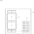
- the figure 1 represents a graphics processor 10, also called GPU (standing for Graphics Processing Unit ), comprising a module 12 for acquiring a character display command, a module 14 for processing a display from one character to another. From an acquired command, the processing module 14 comprising a geometric engine 15 and a rasterization unit 16.
- the graphics processor 10 comprises a buffer memory 18 connected to the processing module 14.
- the graphics processor 10 is, for example, intended to be integrated into a display system, preferably intended to be on board an aircraft, in particular in an aircraft cockpit.
- the graphics processor 10 is configured to generate data for display on a screen 20.
- This data is, for example, data for the display of character (s) such as alphanumeric characters.
- Graphics processor 10 is then configured to generate data for displaying a character at a desired position on screen 20, and with a desired orientation and size. Alternatively, it is configured to generate data for displaying a character at a desired position and with a desired orientation on screen 20, and with a predefined size. As a further variant, it is configured to generate data for displaying a character at a desired position and with an orientation and size defined on screen 20.
- Each character comprises, for example, at least one segment to be displayed on the screen 20. Such characters are then called vector characters.
- each character includes several characteristic points to be displayed on the screen.
- the characteristic points of said character correspond to the ends of the segment or segments of said character.
- each character comprises, for each end of its segments not coincident with another end of its segments, a characteristic point corresponding to said end; and for each end of its segments coinciding with another end of its segments, a single characteristic point for said two ends coinciding.
- the screen 20 is, for example, a monitoring screen intended to be on board an aircraft, in particular in an aircraft cockpit, as known per se.
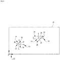
- the figure 2 is a schematic representation of the screen 20 with an absolute mark 22, and on which is represented a character to be displayed 24 comprising segments 26 and characteristic points 28.
- the character to be displayed 24 is any character comprising two segments 26 and three characteristic points 28.
- the screen is rectangular in shape and the absolute frame of reference 22 is an orthonormal frame of origin O corresponding to a vertex of the screen 20.
- the screen 20 is, for example, configured to display characters, from data generated by the graphics processor 10 comprising absolute coordinates of pixels of the screen 20 to be displayed.
- the graphics processor is produced in the form of programmable logic components, such as one or more FPGAs (standing for Field-Programmable Gâte Array), or in the form of dedicated integrated circuits, of the ASIC type (standing for Application -Specific Integrated Circuit).
- programmable logic components such as one or more FPGAs (standing for Field-Programmable Gâte Array), or in the form of dedicated integrated circuits, of the ASIC type (standing for Application -Specific Integrated Circuit).
- the acquisition module 12 is configured to acquire display commands of the character to be displayed 24, in particular originating from a processor or CPU (standing for Central Processing Unit ) .
- the processing module 14 is connected to the acquisition module 12 and is configured to supply geometric data of the character to be displayed 24, from acquired display commands.
- the geometric data of the character to be displayed 24 comprises the absolute coordinates of pixels to be displayed on the screen 20 of the or each segment 26 of the character to be displayed 24.
- the geometric engine 15 also called GE (from the English Geometric Engine ), is configured to supply geometric data of the segment or segments 26 of the character to be displayed 24, from the display command acquired.
- the geometric data of a segment 26 of the character to be displayed 24 comprises, for example, the absolute coordinates of the characteristic points 28 of the character to be displayed 24 corresponding to the ends of said segment 26.
- the rasterization unit 16, or RE standing for Raster Engine
- RE standing for Raster Engine
- the rasterization unit 16, or RE is connected to the geometric engine 15, and is configured to provide the geometric data of the character to be displayed 24 on the screen 20, in particular the absolute coordinates of the characters. pixels to be displayed of the or each segment 26 of said character 24, from the geometric data of the segment or segments 26 of the character to be displayed 24 supplied by the geometric engine 15.
- the buffer memory 18 is configured to store the data of the character to be displayed 24 supplied by the processing module 14, this stored data then being used for the display of the character to be displayed 24 on the screen 20.
- the graphics processor 10 further comprises an electronic device 30 for verifying a character to be displayed 24 on the screen 20 with respect to a reference character 34, the verification device 30 being connected to the buffer memory 18.
- the verifier 30 is configured to verify that the character to be displayed 24 is correct with respect to the reference character 34, that is to say that the character to be displayed 24 is the image of a geometric transformation of the character of reference 34, and therefore that the segments 26 and characteristic points 28 are the images by said geometric transformation of segments 36 and characteristic points 38 of the reference character 34.
- the reference character 34 is shown in figure 2 with two segments 36 and three characteristic points 38.
- the geometric transformation is a transformation or a combination of transformations among the group consisting of a translation, a rotation and a homothety.
- the geometric transformation is then a direct similarity.
- the geometric transformation includes a translation, a rotation and a homothety.
- the verification device 30 comprises a first unit 40 for determining a barycenter G1 of the characteristic points 28 of the character to be displayed 24, a first unit 42 for calculating geometric coordinates of each characteristic point 28 of the character to be displayed 24 in a reference frame 29 centered on the barycenter G1 determined, and a second unit 44 for calculating a difference E between the character to be displayed 24 and the reference character 34.
- the checking device 30 further comprises a unit 46 for comparing the number of characteristic points 28 of the character to be displayed 24 and that of the reference character 34.
- the verification device 30 further comprises a third unit 48 for calculating a geometric transformation between a character among the character to be displayed 24 and the reference character 34, and the other character among the character to display 24 and the reference character 34, and a second unit 50 for determining a position on the screen 20 of the character to be displayed 24, a third unit 52 for determining an orientation on the screen 20 of the character to be displayed. display 24, and in addition, a fourth unit 54 for determining a size on the screen 20 of the character to be displayed 24.
- the first determination unit 40 is configured to determine the barycenter G1 of the characteristic points 28 of the character to be displayed 24, in particular the absolute coordinates (x G1 , y G1 ) of the barycenter G1, from the geometric data of characters to be displayed stored in the buffer memory 18, in particular from the absolute coordinates (x i (a) , y i (a) ) of the pixels corresponding to the characteristic points 28, with i ranging from 1 to N 1 , N 1 being the number of characteristic points 28 of the character to display 24.
- the first calculation unit 42 is configured to calculate the geometric coordinates (x i , y i ) of each characteristic point 28 of the reference character 34 in the reference frame 29, preferably orthonormal, centered on the determined barycenter G1.
- the second calculation unit 44 is configured to calculate the difference E between the character to be displayed 24 and the reference character 34, as a function of the geometric coordinates (x i , y i ) calculated for the character to be displayed 24 and of coordinates predetermined geometric coordinates (X i , Y i ) for the reference character 34.
- the predetermined geometric coordinates (X i , Y i ) are geometric coordinates of the characteristic points 38 of the reference character 34 in a reference frame 39, preferably orthonormal, centered on a barycenter G2 of its characteristic points 38, with i ranging from 1 to N 2 , N 2 being the number of characteristic points 38 of the reference character 34.
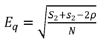
- the second calculation unit 44 is configured for the deviation E as a function of a quadratic error E q between the geometric coordinates (x i , y i ) of the characteristic points 28 of the character to be displayed 24 and those of the characteristic points 38 of the reference character 34, the deviation E preferably being equal to said quadratic error E q .
- the character to be displayed 24 is considered correct if the calculated deviation E is less than a predetermined threshold S.
- the threshold S is determined, for example via preliminary tests, so that when the calculated deviation E is less than said threshold S, each characteristic point 28 of the character to be displayed 24 is distant, by a maximum of two pixels along an abscissa axis of absolute frame 22 and two pixels following an axis of the ordinates of the absolute coordinate system 22, of the image by the geometric transformation of a corresponding characteristic point 38 of the reference character 34.
- the first determination 40 and, respectively, calculation 42 units are further configured to determine the barycenter G2 of the characteristic points 38 for a set of reference characters 34 capable of being displayed on the screen 20, in in particular the absolute coordinates (X G2 , Y G2 ) of the barycenter G2, and respectively to calculate the geometric coordinates (X i Y i ) of each characteristic point 38 for all the reference characters 34 suitable for being displayed on the screen 20 , in reference 39, preferably when starting the graphics processor 10.
- the comparison unit 46 is configured to compare, prior to the determination of the barycenter G1, the number N 1 of characteristic points 28 of the character to be displayed 24 and the number N 2 of characteristic points 38 of the reference character 34 .
- the third calculation unit 48 is configured to calculate, after calculating the geometric coordinates (x i , y i ) of the characteristic points 28 of the character to be displayed 24, the geometric transformation between a character among the character to be displayed 24 and the reference character 34, and the other character of the display character 24 and the reference character 34.
- the third calculation unit 48 is configured to determine a translation vector between the character to be displayed 24 and the reference character 34.
- the determined translation vector corresponds to a vector between the barycenter G1 of the character to be displayed 24 and the barycenter G2 of the reference character 34.
- the third calculation unit 48 is configured to calculate a homothety factor A between the character to be displayed 24 and the reference character 34, according to the equation [Math 13].
- the second determination unit 50 is configured to determine the position of the reference character 24, as a function of the calculated geometric transformation, in particular as a function of the determined translation vector, and as a function of a predetermined position of the reference character 34.
- the third determination unit 52 is configured to determine the orientation of the reference character 24, based on the calculated geometric transformation, in particular based on the calculated rotation angle ⁇ , and based on a predetermined orientation of the character. reference 34.
- the fourth determination unit 54 is configured to determine the size of the reference character 24, according to the calculated geometric transformation, in particular according to the calculated scaling factor A, and according to a predetermined size of the reference character. 34.
- the verification device 30 is a device external to the graphics processor 10.
- the graphics processor 10 comprises a module for transmitting geometric data of the character to be displayed 24 to the verification device 30, and a module for receiving verification data from the verification device 30.
- the verification device 30 is as defined above, and further comprises, a unit for receiving geometric data of the character to be displayed 24 from the graphics processor 10, and a unit for sending verification data to the graphics processor 10.
- the verification data comprises data indicating whether the character to be displayed is correct or not, and as an optional addition to the data comprising the position, orientation and, as a further complement, the size of the character to be displayed 24.
- the verification device 30 is, for example, produced in the form of programmable logic components, such as one or more FPGAs (standing for Field-Programmable Gâte Array), or else in the form of dedicated integrated circuits, of the ASIC type.
- programmable logic components such as one or more FPGAs (standing for Field-Programmable Gâte Array), or else in the form of dedicated integrated circuits, of the ASIC type.
- the verification device 30 comprises an information processing unit, comprising a memory, and a processor associated with the memory.
- the first determination unit 40, the first and second calculation units 42 and 44, as well as as an optional complement, the comparison unit 46, the third calculation unit 48 and the second, third and fourth determination units 50, 52 and 54, as well as the reception and transmission units, are then each produced in the form of software, or a software brick, which can be executed by the processor.
- the memory is then able to store a first software for determining the barycenter G1 of the characteristic points 28 of the character to be displayed 24, a first software for calculating the geometric coordinates (x i , y i ) of each characteristic point 28 of the character to be displayed 24 , a second software for calculating the difference E between the character to be displayed 24 and the reference character 34, and as an optional supplement a software for comparing the number N 1 of characteristic points 28 of the character to be displayed 24 and the number N 2 of characteristic points 38 of the reference character 34, a third software for calculating the geometric transformation between a character among the character to be displayed 24 and the reference character 34, and the other character among the character to be displayed 24 and the reference character 34, a second software for determining the position of the character to be displayed 24 , a third software for determining the orientation of the character to be displayed 24, and a fourth software for determining the size of the character to be displayed 24, as well as software for receiving geometric data of the character to be displayed 24 from the graphics processor 10 and software for sending verification
- the verification device 30 When the verification device 30 is produced in the form of one or more software, that is to say in the form of a computer program product, it is also able to be recorded on a medium, not shown, computer readable.
- the computer readable medium is, for example, a medium capable of memorizing electronic instructions and of being coupled to a bus of a computer system.
- the readable medium is an optical disc, a magneto-optical disc, a ROM memory, a RAM memory, any type of non-volatile memory (for example EPROM, EEPROM, FLASH, NVRAM), a magnetic card or an optical card.
- On the readable medium is then stored a computer program product comprising software instructions.
- a method for verifying the character to be displayed 24 on the screen 20 with respect to the reference character 34, implemented by the verification device 30, will now be described, with reference to the figure 3 .
- the method comprises a step 210 of determining, by the first determination unit 40, the barycenter G1 of the characteristic points 28 of the character to be displayed 24.
- the first determination unit 40 calculates the absolute coordinates (x G1 , y G1 ) of the barycenter G1, from the absolute coordinates (x i (a) , y i (a) ) of the characteristic points 28 of the reference character 34, for example, according to the equations [Math 1] and [Math 2] .
- the method then comprises a step 220 of calculating, by the first calculation unit 42, the geometric coordinates (x i , y i ) of each characteristic point 28 of the character to be displayed 24.
- the first calculation unit 42 calculates the geometric coordinates (x i , y i ) of each characteristic point 28, according to the equations [Math 3] and [Math 4].
- the method comprises a step 230 of calculating, by the second calculation unit 44, the difference E between the character to be displayed 24 and the reference character 34.
- the second calculation unit 44 calculates the deviation E, preferably as a function of the quadratic error E q , for example according to the equation [Math 7].
- the second computing unit 44 calculates the deviation E as a function of the squared error E q , according to the equation [Math 6].
- the second calculation unit 44 calculates the deviation E as a function of the squared error E q , following the equation [Math 5].
- the character to be displayed 24 is considered correct only if the calculated deviation E is less than the predetermined threshold S.
- the method comprises, prior to the determination step 210, a step 200 of comparison, by the comparison unit 46, of the number N 1 of characteristic points 28 of the character to be displayed 24 and of the number N 2 of characteristic points 38 of the reference character 34.
- the following determination step 210 is then performed, only if the number N 1 of characteristic points 28 of the character to be displayed 24 and that N 2 of the reference character 34 are equal.
- the character to be displayed 24 is considered incorrect and the following steps are not carried out, if the number N 1 of characteristic points 28 of the character to be displayed 24 differs from the number N 2 of characteristic points 38 of the reference character 34.
- the method comprises, according to the calculation step 220, a step 240 of calculating, by the third calculation unit 48, the geometric transformation between a character among the character to be displayed 24 and the reference character 34 , and the other character among the character to be displayed 24 and the reference character 34.
- the third calculation unit 48 calculates, for example, the translation vector as a function of the calculated barycenter G1, the angle of rotation ⁇ according to the equations [Math 14] and [Math 15] and the homothety factor ⁇ of the geometric transformation according to the equation [Math 13].
- the third computing unit 48 only calculates the translation vector and the rotation angle ⁇ .
- graphics processor 10 when graphics processor 10 is configured to display a character with a predefined orientation and size, only the translation vector is calculated.
- the method then comprises a step 250 of determining, by the second determination unit 50, the position on the screen 20 of the character to be displayed 24, as a function of the calculated geometric transformation, in particular of the calculated translation vector, and as a function of the predetermined position of the reference character 34.
- the method further comprises a step 260 of determining, by the third determination unit 52 of the orientation on the screen 20 of the character to be displayed 24, as a function of the calculated geometric transformation, in particular of the angle of the rotation ⁇ calculated, and according to the predetermined orientation of the reference character 34
- the method further comprises, following the determination step 240, a step 270 of calculating, by the fourth determination unit 54, the size on the screen 20 of the character to be displayed 24, in particular the factor of homothety ⁇ calculated, and according to the predetermined size of the reference character 34.
- step 260 is carried out following step 250 and step 270 is carried out following step 260.
- steps 250 to 270 are carried out in any order.
- step 270 is not performed.
- steps 260 and 270 are not performed.
- steps 240 to 270 are performed only after the character to be displayed 24 has been considered correct at the end of step 230.
- steps 240 to 270 are performed between steps 220 and 230.
- the method further comprises a preliminary step, not shown, of reception, from the graphics processor 10, of data. geometric characteristics of the character to be displayed 24, and a final step, not shown, of transmitting verification data to the graphics processor 10.
- the verification device 30 makes it possible to verify the character to be displayed 24 with respect to the reference character 34 just before its display on the screen 20, which makes it possible to guarantee a correct display of this character, whatever or its position, size and orientation.
- the calculation of the position, orientation and size of the character to be displayed 24 makes it possible to verify that the character is displayed at a desired position on the screen 20, and with a desired orientation and size.
- Such a verification device 30 then makes it possible to verify the character to be displayed 24 with a limited number of calculations, which allows the verification device 30 to verify a large number of characters during a short period of time, for example less than 250 microseconds per 1000 characters when the verifier 30 is a device external to the graphics processor 10.
- the calculation of the difference E is optimized as a function of the geometric transformation between the character to be displayed 24 and the reference character 34.
Landscapes
- Engineering & Computer Science (AREA)
- Physics & Mathematics (AREA)
- General Physics & Mathematics (AREA)
- Theoretical Computer Science (AREA)
- Multimedia (AREA)
- Computer Vision & Pattern Recognition (AREA)
- Computer Hardware Design (AREA)
- Computer Graphics (AREA)
- Geometry (AREA)
- Algebra (AREA)
- Mathematical Analysis (AREA)
- Mathematical Optimization (AREA)
- Mathematical Physics (AREA)
- Pure & Applied Mathematics (AREA)
- Controls And Circuits For Display Device (AREA)
- Image Analysis (AREA)
- Image Generation (AREA)
Abstract
Description
- La présente invention concerne un procédé et un dispositif électronique de vérification d'un caractère à afficher sur un écran, par rapport à un caractère de référence.
- L'invention concerne également un produit programme d'ordinateur comprenant des instructions logicielles qui, lorsqu'elles sont exécutées par un ordinateur, mettent en œuvre un tel procédé de vérification.
- L'invention concerne également un processeur graphique comprenant un tel dispositif électronique de vérification.
- L'invention concerne le domaine des systèmes d'affichage de données, de préférence destinés à être embarqués à bord d'un aéronef, notamment dans un cockpit d'aéronef.
- L'invention concerne en particulier le domaine des processeurs graphiques inclus dans ces systèmes d'affichage, ces processeurs graphiques étant également généralement appelés GPU (de l'anglais Graphie Processing Unit). De tels processeurs graphiques sont typiquement réalisés sous forme d'un ou plusieurs circuits intégrés dédiés, tels qu'un ou plusieurs ASIC (de l'anglais Application Specific Integrated Circuit).
- On connaît alors un processeur graphique du type précité permettant d'afficher notamment des caractères sur un écran de monitoring d'un aéronef afin d'aider au pilotage de l'aéronef.
- Toutefois, en cas d'erreur du processeur graphique, les caractères peuvent être mal affichés sur l'écran. Le processeur graphique peut aussi afficher un mauvais caractère.
- Le but de l'invention est alors de proposer un procédé et un dispositif électronique de vérification permettant de vérifier de façon précise un caractère à afficher sur un écran.
- A cet effet, l'invention a pour objet un procédé de vérification d'un caractère à afficher sur un écran, par rapport à un caractère de référence. Le caractère à afficher et le caractère de référence comprennent chacun au moins plusieurs points caractéristiques à afficher sur l'écran. Le procédé est caractérisé en ce qu'il comprend les étapes suivantes : la détermination d'un barycentre des points caractéristiques du caractère à afficher ; le calcul de coordonnées géométriques de chaque point caractéristique du caractère à afficher dans un repère centré sur le barycentre déterminé ; et le calcul d'un écart entre le caractère à afficher et le caractère de référence, en fonction des coordonnées géométriques calculées pour le caractère à afficher et de coordonnées géométriques prédéterminées pour le caractère de référence, lesdites coordonnées géométriques prédéterminées étant des coordonnées géométriques points caractéristiques du caractère de référence dans un repère centré sur un barycentre de ses points caractéristiques. Le caractère à afficher est considéré correct seulement si l'écart calculé est inférieur à un seuil prédéterminé.
- Un tel procédé de vérification permet de vérifier qu'un caractère à afficher sur un écran est correct par rapport à un caractère de référence, quelle que soit la position, la taille et l'orientation du caractère à afficher sur l'écran. En effet, l'utilisation du barycentre de chaque caractère comme centre d'un repère permet d'obtenir des coordonnées géométriques des points caractéristiques comparables les unes par rapport aux autres, et le calcul de l'écart entre le caractère à afficher et le caractère de référence permet vérifier si les points caractéristiques du caractère à afficher sont positionnés correctement, ce qui permet de s'assurer que son affichage est correct, si l'écart calculé est inférieur au seuil prédéterminé, quelle que soit sa position, sa taille et son orientation.
- Suivant d'autres aspects avantageux, le procédé de vérification comporte l'une ou plusieurs des caractéristiques suivantes :
- le procédé comprend, en outre, les étapes suivantes, après à l'étape de calcul des coordonnées géométriques : le calcul d'une transformation géométrique entre un caractère parmi le caractère à afficher et le caractère de référence, et l'autre caractère parmi le caractère à afficher et le caractère de référence ; la détermination d'une position à l'écran du caractère à afficher, en fonction de la transformation géométrique calculée et d'une position du caractère de référence prédéterminée ; et la détermination d'une orientation à l'écran du caractère à afficher, en fonction de la transformation géométrique calculée et d'une orientation du caractère de référence prédéterminée,
- le procédé comprend, en outre, après l'étape de calcul de la transformation géométrique, une étape de détermination d'une taille à l'écran du caractère à afficher, en fonction de la transformation géométrique calculée et d'une taille du caractère de référence prédéterminée,
- le procédé comprend préalablement à l'étape de détermination du barycentre, une étape de comparaison du nombre de points caractéristiques du caractère à afficher et de celui du caractère de référence, le caractère à afficher étant considéré incorrect et les étapes suivantes n'étant pas effectuées, si le nombre de points caractéristiques du caractère à afficher diffère de celui du caractère de référence,
- lors de l'étape de calcul de l'écart, l'écart entre le caractère à afficher et le caractère de référence est calculé en fonction d'une erreur quadratique entre les coordonnées géométriques des points caractéristiques du caractère à afficher et celles des points caractéristiques du caractère de référence,
- le caractère à afficher est l'image d'une transformation géométrique du caractère de référence, la transformation géométrique étant une similitude directe, le nombre de points caractéristiques du caractère à afficher et le nombre de points caractéristiques du caractère de référence sont égaux, et l'erreur quadratique vérifie l'une des équations suivantes :



- le caractère à afficher et le caractère de référence comprennent chacun au moins un segment à afficher sur l'écran, les points caractéristiques dudit caractère correspondant à des extrémités de l'au moins un segment.
- L'invention a également pour objet un produit programme d'ordinateur comprenant des instructions logicielles qui, lorsqu'elles sont exécutées par un ordinateur, mettent en œuvre un procédé de vérification tel que défini ci-dessus.
- L'invention a également pour objet un dispositif électronique de vérification d'un caractère à afficher sur un écran par rapport à un caractère de référence. Le caractère à afficher et le caractère de référence comprennent chacun plusieurs points caractéristiques à afficher sur l'écran. Le dispositif de vérification étant caractérisé en ce qu'il comprend une unité de détermination d'un barycentre des points caractéristiques du caractère à afficher ; une première unité de calcul de coordonnées géométriques de chaque point caractéristique du caractère à afficher dans un repère centré sur le barycentre déterminé ; et une deuxième unité de calcul d'un écart entre le caractère à afficher et le caractère de référence, en fonction des coordonnées géométriques calculées pour le caractère à afficher et de coordonnées géométriques prédéterminées pour le caractère de référence, lesdites coordonnées géométriques prédéterminées étant des coordonnées géométriques des points caractéristiques du caractère de référence dans un repère centré sur un barycentre de ses points caractéristiques. Le caractère à afficher est considéré correct seulement si l'écart calculé est inférieur à un seuil prédéterminé.
- L'invention a également pour objet un processeur graphique comprenant un dispositif électronique de vérification, tel que défini ci-dessus.
- Ces caractéristiques et avantages de l'invention apparaîtront à la lecture de la description qui va suivre, donnée uniquement à titre d'exemple non limitatif, et faite en référence aux dessins annexés sur lesquels :
- [
Fig 1 ] lafigure 1 est une représentation schématique d'un processeur graphique comprenant un dispositif de vérification selon l'invention, - [
Fig 2 ] lafigure 2 est une représentation schématique d'un écran sur lequel sont représentés un caractère à afficher et un caractère de référence, et - [
Fig 3 ] lafigure 3 est un organigramme d'un procédé de vérification selon l'invention. - La
figure 1 représente un processeur graphique 10, aussi appelé GPU (de l'anglais Graphics Processing Unit), comprenant un module 12 d'acquisition de commande d'affichage d'un caractère, un module 14 de traitement d'un affichage d'un caractère à partir d'une commande acquise, le module de traitement 14 comportant un moteur géométrique 15 et une unité de rastérisation 16. Le processeur graphique 10 comprend une mémoire tampon 18 connectée au module de traitement 14. - Le processeur graphique 10 est, par exemple, destiné à être intégré dans un système d'affichage, de préférence, destiné à être embarqué à bord d'un aéronef, notamment dans un cockpit d'aéronef.
- Le processeur graphique 10 est configuré pour générer des données pour un affichage sur un écran 20. Ces données sont, par exemple, des données pour l'affichage de caractère(s) tel(s) que des caractères alphanumériques.
- Le processeur graphique 10 est alors configuré pour générer des données pour l'affichage d'un caractère à une position souhaitée sur l'écran 20, et avec une orientation et une taille souhaitée. En variante, il est configuré pour générer des données pour l'affichage d'un caractère à une position souhaitée et avec une orientation souhaitée sur l'écran 20, et avec une taille prédéfinie. En variante encore, il est configuré pour générer des données pour l'affichage d'un caractère à une position souhaitée et avec une orientation et une taille définies sur l'écran 20.
- Chaque caractère comprend, par exemple, au moins un segment à afficher sur l'écran 20. De tels caractères sont alors appelés caractères vectoriels.
- En outre, chaque caractère comprend plusieurs points caractéristiques à afficher sur l'écran. De préférence, les points caractéristiques dudit caractère correspondent aux extrémités du ou des segments dudit caractère. Avantageusement, chaque caractère comprend, pour chaque extrémité de ses segments non confondue avec une autre extrémité de ses segments, un point caractéristique correspondant à ladite extrémité ; et pour chaque extrémité de ses segments confondue avec une autre extrémité de ses segments, un unique point caractéristique pour lesdites deux extrémités confondues.
- L'écran 20 est, par exemple, un écran de monitoring destiné à être embarqué à bord d'un aéronef, notamment dans un cockpit d'aéronef, comme connu en soi.
- La
figure 2 est une représentation schématique de l'écran 20 avec un repère absolu 22, et sur lequel est représenté un caractère à afficher 24 comprenant des segments 26 et des points caractéristiques 28. - A titre d'exemple, le caractère à afficher 24 est un caractère quelconque comprenant deux segments 26 et trois points caractéristiques 28.
- Dans l'exemple de la
figure 2 , l'écran est de forme rectangulaire et le repère absolu 22 est un repère orthonormé d'origine O correspondant à un sommet de l'écran 20. - On appelle coordonnées absolues d'un pixel, les coordonnées cartésiennes dudit pixel prises dans le repère absolu 22.
- L'écran 20 est, par exemple, configuré pour afficher des caractères, à partir de données générées par le processeur graphique 10 comprenant des coordonnées absolues de pixels de l'écran 20 à afficher.
- Dans l'exemple de la
figure 1 , le processeur graphique est réalisé sous forme de composants logiques programmables, tel qu'un ou plusieurs FPGA (de l'anglais Field-Programmable Gâte Array), ou encore sous forme de circuits intégrés dédiés, de type ASIC (de l'anglais Application-Specific Integrated Circuit). - Le module d'acquisition 12 est configuré pour acquérir des commandes d'affichage du caractère à afficher 24, notamment issues d'un processeur ou CPU (de l'anglais Central Processing Unit).
- Le module de traitement 14 est connecté au module d'acquisition 12 et est configuré pour fournir des données géométriques du caractère à afficher 24, à partir de commandes d'affichage acquises. Par exemple, les données géométriques du caractère à afficher 24 comprennent les coordonnées absolues de pixels à afficher sur l'écran 20 du ou de chaque segment 26 du caractère à afficher 24.
- Le moteur géométrique 15, aussi appelé GE (de l'anglais Geometric Engine), est configuré pour fournir des données géométriques du ou des segments 26 du caractère à afficher 24, à partir de la commande d'affichage acquise.
- Les données géométriques d'un segment 26 du caractère à afficher 24 comprennent, par exemple, les coordonnées absolues des points caractéristiques 28 du caractère à afficher 24 correspondant aux extrémités dudit segment 26.
- L'unité de rastérisation 16, ou RE (de l'anglais Raster Engine), est connectée au moteur géométrique 15, et est configurée pour fournir les données géométriques du caractère à afficher 24 sur l'écran 20, en particulier les coordonnées absolues des pixels à afficher du ou de chaque segment 26 dudit caractère 24, à partir des données géométriques du ou des segments 26 du caractère à afficher 24 fournies par le moteur géométrique 15.
- La mémoire tampon 18 est configurée pour stocker les données du caractère à afficher 24 fournies par le module de traitement 14, ces données stockées étant ensuite utilisées pour l'affichage du caractère à afficher 24 sur l'écran 20.
- Le processeur graphique 10 comprend, en outre, un dispositif électronique 30 de vérification d'un caractère à afficher 24 sur l'écran 20 par rapport à un caractère de référence 34, le dispositif de vérification 30 étant connecté à la mémoire tampon 18.
- Le dispositif de vérification 30 est configuré pour vérifier que le caractère à afficher 24 est correct par rapport au caractère de référence 34, c'est-à-dire que le caractère à afficher 24 est l'image d'une transformation géométrique du caractère de référence 34, et donc que les segments 26 et points caractéristiques 28 sont les images par ladite transformation géométrique de segments 36 et points caractéristiques 38 du caractère de référence 34. A titre d'exemple, le caractère de référence 34 est représenté sur la
figure 2 avec deux segments 36 et trois points caractéristiques 38. - Dans la suite et à titre d'exemple, la transformation géométrique est une transformation ou une combinaison de transformations parmi le groupe constitué d'une translation, d'une rotation et d'une homothétie. La transformation géométrique est alors une similitude directe.
- Dans l'exemple de la
figure 2 , la transformation géométrique comprend une translation, une rotation et une homothétie. - Le dispositif de vérification 30 comporte une première unité 40 de détermination d'un barycentre G1 des points caractéristiques 28 du caractère à afficher 24, une première unité 42 de calcul de coordonnées géométriques de chaque point caractéristique 28 du caractère à afficher 24 dans un repère 29 centré sur le barycentre G1 déterminé, et une deuxième unité 44 de calcul d'un écart E entre le caractère à afficher 24 et le caractère de référence 34.
- En complément facultatif, le dispositif de vérification 30 comprend, en outre, une unité 46 de comparaison du nombre de points caractéristiques 28 du caractère à afficher 24 et de celui du caractère de référence 34.
- En complément facultatif encore, le dispositif de vérification 30 comprend, en outre, une troisième unité 48 de calcul d'une transformation géométrique entre un caractère parmi le caractère à afficher 24 et le caractère de référence 34, et l'autre caractère parmi le caractère à afficher 24 et le caractère de référence 34, et une deuxième unité 50 de détermination d'une position à l'écran 20 du caractère à afficher 24, une troisième unité 52 de détermination d'une orientation à l'écran 20 du caractère à afficher 24, et en complément, une quatrième unité 54 de détermination d'une taille à l'écran 20 du caractère à afficher 24.
- La première unité de détermination 40 est configurée pour déterminer le barycentre G1 des points caractéristiques 28 du caractère à afficher 24, en particulier les coordonnées absolues (xG1, yG1) du barycentre G1, à partir des données géométriques de caractères à afficher stockées dans la mémoire tampon 18, en particulier à partir des coordonnées absolues (xi (a), yi (a)) des pixels correspondant aux points caractéristiques 28, avec i allant de 1 à N1, N1 étant le nombre de points caractéristiques 28 du caractère à afficher 24.
- La première unité de détermination 40 est, par exemple, configurée pour calculer les coordonnées absolues (xG1, yG1) du barycentre G1 suivant les équations suivantes :


- La première unité de calcul 42 est configurée pour calculer les coordonnées géométriques (xi, yi) de chaque point caractéristique 28 du caractère de référence 34 dans le repère 29, de préférence orthonormé, centré sur le barycentre G1 déterminé.
- Les coordonnées géométriques (xi, yi) des points caractéristiques 28 vérifient alors les équations suivantes :


- La deuxième unité de calcul 44 est configurée pour calculer l'écart E entre le caractère à afficher 24 et le caractère de référence 34, en fonction des coordonnées géométriques (xi, yi) calculées pour le caractère à afficher 24 et de coordonnées géométriques (Xi, Yi) prédéterminées pour le caractère de référence 34. Les coordonnées géométriques (Xi, Yi) prédéterminées sont des coordonnées géométriques des points caractéristiques 38 du caractère de référence 34 dans un repère 39, de préférence orthonormé, centré sur un barycentre G2 de ses points caractéristiques 38, avec i allant de 1 à N2, N2 étant le nombre de points caractéristiques 38 du caractère de référence 34.
- Par exemple, la deuxième unité de calcul 44 est configurée pour l'écart E en fonction d'une erreur quadratique Eq entre les coordonnées géométriques (xi, yi) des points caractéristiques 28 du caractère à afficher 24 et celles des points caractéristiques 38 du caractère de référence 34, l'écart E étant de préférence égal à ladite erreur quadratique Eq.
- De préférence, la deuxième unité de calcul 44 est configurée pour calculer l'erreur quadratique Eq en fonction de la transformation géométrique entre le caractère à afficher 24 et le caractère de référence 34, en supposant le nombre N1 de points caractéristiques 28 du caractère à afficher 24 égal à celui N2 du caractère de référence 34, N = N1 = N2 représentant alors ledit nombre de points caractéristiques 28, 38, selon les équations suivantes :


avec





- Le caractère à afficher 24 est considéré correct si l'écart calculé E est inférieur à un seuil S prédéterminé.
- Avantageusement, le seuil S est déterminé, par exemple via des essais préliminaires, de manière à ce que lorsque l'écart calculé E est inférieur audit seuil S, chaque point caractéristique 28 du caractère à afficher 24 est distant, d'un maximum de deux pixels suivant un axe des abscisses du repère absolu 22 et de deux pixels suivant un axe des ordonnées du repère absolu 22, de l'image par la transformation géométrique d'un point caractéristique 38 correspondant du caractère de référence 34.
- Par exemple, les premières unités de détermination 40 et, respectivement, de calcul 42 sont, en outre, configurées pour déterminer le barycentre G2 des points caractéristiques 38 pour un ensemble de caractères de référence 34 aptes à être affiché à l'écran 20, en particulier les coordonnées absolues (XG2, YG2) du barycentre G2, et respectivement pour calculer les coordonnées géométriques (Xi Yi) de chaque point caractéristique 38 pour l'ensemble des caractères de référence 34 aptes être affiché à l'écran 20, dans le repère 39, de préférence au démarrage du processeur graphique 10.
- En complément facultatif, l'unité de comparaison 46 est configurée pour comparer, préalablement à la détermination du barycentre G1, le nombre N1 de points caractéristiques 28 du caractère à afficher 24 et le nombre N2 de points caractéristiques 38 du caractère de référence 34.
- En complément facultatif encore, la troisième unité de calcul 48 est configurée pour calculer, après le calcul des coordonnées géométriques (xi, yi) des points caractéristiques 28 du caractère à afficher 24, la transformation géométrique entre un caractère parmi le caractère à afficher 24 et le caractère de référence 34, et l'autre caractère parmi le caractère à afficher 24 et le caractère de référence 34.
- En particulier, la troisième unité de calcul 48 est configurée pour déterminer un vecteur de translation entre le caractère à afficher 24 et le caractère de référence 34. Le vecteur de translation déterminé correspond à un vecteur entre le barycentre G1 du caractère à afficher 24 et le barycentre G2 du caractère de référence 34.
- En complément, la troisième unité de calcul 48 est configurée pour calculer un angle de rotation θ entre le caractère à afficher 24 et le caractère de référence 34, suivant les équations suivantes :


- En complément encore, la troisième unité de calcul 48 est configurée pour calculer un facteur d'homothétie A entre le caractère à afficher 24 et le caractère de référence 34, suivant l'équation [Math 13].
- La deuxième unité de détermination 50 est configurée pour déterminer la position du caractère de référence 24, en fonction de la transformation géométrique calculée, en particulier en fonction du vecteur de translation déterminé, et en fonction d'une position prédéterminée du caractère de référence 34.
- La troisième unité de détermination 52 est configurée pour déterminer l'orientation du caractère de référence 24, en fonction de la transformation géométrique calculée, en particulier en fonction de l'angle de rotation θ calculé, et en fonction d'une orientation prédéterminée du caractère de référence 34.
- La quatrième unité de détermination 54 est configurée pour déterminer la taille du caractère de référence 24, en fonction de la transformation géométrique calculée, en particulier en fonction du facteur d'homothétie A calculé, et en fonction d'une taille prédéterminée du caractère de référence 34.
- En variante non représentée, le dispositif de vérification 30 est un dispositif externe au processeur graphique 10. Selon cette variante, le processeur graphique 10 comprend un module d'émission de données géométriques du caractère à afficher 24 à destination du dispositif de vérification 30, et un module de réception de données de vérification de la part du dispositif de vérification 30. Selon cette variante, le dispositif de vérification 30 est tel que défini ci-dessus, et comprend en outre, une unité de réception des données géométriques du caractère à afficher 24 de la part du processeur graphique 10, et une unité d'émission des données de vérification à destination du processeur graphique 10.
- Les données de vérification comprennent des données indiquant si le caractère à afficher est correct ou non, et en complément facultatif des données comprenant la position, l'orientation et, en complément encore, la taille du caractère à afficher 24.
- Le dispositif de vérification 30 est, par exemple, réalisé sous forme de composants logiques programmables, tel qu'un ou plusieurs FPGA (de l'anglais Field-Programmable Gâte Array), ou encore sous forme de circuits intégrés dédiés, de type ASIC.
- En variante non représentée, le dispositif de vérification 30 comprend une unité de traitement d'informations, comportant une mémoire, et un processeur associé à la mémoire. La première unité de détermination 40, les première et deuxième unités de calcul 42 et 44, ainsi qu'en complément facultatif, l'unité de comparaison 46, la troisième unité de calcul 48 et les deuxième, troisième et quatrième unités de détermination 50, 52 et 54, ainsi que les unités de réception et d'émission, sont alors réalisées chacun sous forme d'un logiciel, ou d'une brique logicielle, exécutables par le processeur. La mémoire est alors apte à stocker un premier logiciel de détermination du barycentre G1 des points caractéristiques 28 du caractère à afficher 24, un premier logiciel de calcul des coordonnées géométriques (xi, yi) de chaque point caractéristique 28 du caractère à afficher 24, un deuxième logiciel de calcul de l'écart E entre le caractère à afficher 24 et le caractère de référence 34, et en complément facultatif un logiciel de comparaison du nombre N1 de points caractéristiques 28 du caractère à afficher 24 et du nombre N2 de points caractéristiques 38 du caractère de référence 34, un troisième logiciel de calcul de la transformation géométrique entre un caractère parmi le caractère à afficher 24 et le caractère de référence 34, et l'autre caractère parmi le caractère à afficher 24 et le caractère de référence 34, un deuxième logiciel de détermination de la position du caractère à afficher 24, un troisième logiciel de détermination de l'orientation du caractère à afficher 24, et un quatrième logiciel de détermination de la taille du caractère à afficher 24, ainsi qu'un logiciel de réception de données géométriques du caractère à afficher 24 de la part du processeur graphique 10 et un logiciel d'émission de données de vérification à destination du processeur graphique 10.
- Lorsque le dispositif de vérification 30 est réalisé sous forme d'un ou plusieurs logiciels, c'est-à-dire sous forme d'un produit programme d'ordinateur, il est en outre apte à être enregistré sur un support, non représenté, lisible par ordinateur. Le support lisible par ordinateur est par exemple, un médium apte à mémoriser des instructions électroniques et à être couplé à un bus d'un système informatique. A titre d'exemple, le support lisible est un disque optique, un disque magnéto-optique, une mémoire ROM, une mémoire RAM, tout type de mémoire non volatile (par exemple EPROM, EEPROM, FLASH, NVRAM), une carte magnétique ou une carte optique. Sur le support lisible est alors mémorisé un produit programme d'ordinateur comprenant des instructions logicielles.
- Un procédé de vérification du caractère à afficher 24 sur l'écran 20 par rapport au caractère de référence 34, mis en œuvre par le dispositif de vérification 30, va maintenant être décrit, en regard de la
figure 3 . - Le procédé comprend une étape 210 de détermination, par la première unité de détermination 40, du barycentre G1 des points caractéristiques 28 du caractère à afficher 24. Lors de cette étape 210, la première unité de détermination 40 calcule les coordonnées absolues (xG1, yG1) du barycentre G1, à partir des coordonnées absolues (xi (a), yi (a)) des points caractéristiques 28 du caractère de référence 34, par exemple, suivant les équations [Math 1] et [Math 2].
- Le procédé comprend ensuite une étape 220 de calcul, par la première unité de calcul 42, des coordonnées géométriques (xi, yi) de chaque point caractéristique 28 du caractère à afficher 24. Lors de cette étape 210, la première unité de calcul 42 calcule les coordonnées géométriques (xi, yi) de chaque point caractéristique 28, suivant les équations [Math 3] et [Math 4].
- Enfin, le procédé comprend une étape 230 de calcul, par la deuxième unité de calcul 44, de l'écart E entre le caractère à afficher 24 et le caractère de référence 34.
- Pendant l'étape de calcul 230, la deuxième unité de calcul 44 calcule l'écart E, de préférence en fonction de l'erreur quadratique Eq, par exemple suivant l'équation [Math 7].
- En variante, lorsque le processeur graphique 10 est configuré pour afficher un caractère avec une taille prédéfinie, la deuxième unité de calcul 44 calcule l'écart E en fonction de l'erreur quadratique Eq, suivant l'équation [Math 6].
- En variante encore, lorsque le processeur graphique 10 est configuré pour afficher un caractère avec une orientation et une taille prédéfinies, la deuxième unité de calcul 44 calcule l'écart E en fonction de l'erreur quadratique Eq, suivant l'équation [Math 5].
- Le caractère à afficher 24 est considéré correct seulement si l'écart E calculé est inférieur au seuil S prédéterminé.
- En complément facultatif, le procédé comprend, préalablement à l'étape de détermination 210, une étape 200 de comparaison, par l'unité de comparaison 46, du nombre N1 de points caractéristiques 28 du caractère à afficher 24 et du nombre N2 de points caractéristiques 38 du caractère de référence 34.
- L'étape suivante de détermination 210 est effectuée ensuite, seulement si le nombre N1 de points caractéristiques 28 du caractère à afficher 24 et celui N2 du caractère de référence 34 sont égaux.
- Le caractère à afficher 24 est considéré incorrect et les étapes suivantes ne sont pas effectuées, si le nombre N1 de points caractéristiques 28 du caractère à afficher 24 diffère du nombre N2 de points caractéristiques 38 du caractère de référence 34.
- En complément facultatif encore, le procédé comprend, suivant l'étape de calcul 220, une étape 240 de calcul, par la troisième unité de calcul 48, de la transformation géométrique entre un caractère parmi le caractère à afficher 24 et le caractère de référence 34, et l'autre caractère parmi le caractère à afficher 24 et le caractère de référence 34.
- Lors de l'étape 240, la troisième unité de calcul 48 calcule, par exemple, le vecteur de translation en fonction du barycentre G1 calculé, l'angle de la rotation θ suivant les équations [Math 14] et [Math 15] et le facteur d'homothétie λ de la transformation géométrique suivant l'équation [Math 13].
- En variante, lorsque le processeur graphique 10 est configuré pour afficher un caractère avec une taille prédéfinie, la troisième unité de calcul 48 calcule uniquement le vecteur de translation et l'angle de rotation θ.
- En variante encore, lorsque le processeur graphique 10 est configuré pour afficher un caractère avec une orientation et une taille prédéfinies, calcule uniquement le vecteur de translation.
- Le procédé comprend alors une étape 250 de détermination, par la deuxième unité de détermination 50, de la position à l'écran 20 du caractère à afficher 24, en fonction de la transformation géométrique calculée, en particulier du vecteur de translation calculé, et en fonction de la position prédéterminée du caractère de référence 34.
- Le procédé comprend, en outre une étape 260 de détermination, par la troisième unité de détermination 52 de l'orientation à l'écran 20 du caractère à afficher 24, en fonction de la transformation géométrique calculée, en particulier de l'angle de la rotation θ calculé, et en fonction de l'orientation prédéterminée du caractère de référence 34
- De préférence, le procédé comprend, en outre, suivant l'étape de détermination 240, une étape 270 de calcul, par la quatrième unité de détermination 54, de la taille à l'écran 20 du caractère à afficher 24, en particulier du facteur d'homothétie λ calculé, et en fonction de la taille prédéterminée du caractère de référence 34.
- Dans l'exemple de la
figure 3 , l'étape 260 est effectuée à la suite de l'étape 250 et l'étape 270 est effectuée à la suite de l'étape 260. En variante non représentée, les étapes 250 à 270 sont effectuées dans n'importe quel ordre. - En variante, lorsque le processeur graphique 10 est configuré pour afficher un caractère avec une taille prédéfinie, l'étape 270 n'est pas effectuée.
- En variante encore, lorsque le processeur graphique 10 est configuré pour afficher un caractère avec une orientation et une taille prédéfinies, les étapes 260 et 270 ne sont pas effectuées.
- Dans l'exemple de la
figure 3 , les étapes 240 à 270 sont effectuées seulement après que le caractère à afficher 24 a été considéré correct à l'issue de l'étape 230. - Alternativement, les étapes 240 à 270 sont effectuées entre les étapes 220 et 230.
- Selon cette alternative, lors de l'étape de calcul 230, la deuxième unité de calcul 44 calcule l'écart E en fonction de la transformation géométrique calculée. Plus particulièrement, la deuxième unité de calcul 44 calcule l'écart E en fonction l'erreur quadratique Eq, suivant :
- l'équation [Math 7], si le facteur d'homothétie λ calculé est différent de 1, i.e. si la transformation géométrique calculée comprend une homothétie.
- l'équation [Math 6], si le facteur d'homothétie λ calculé est égal à 1 et l'angle de la rotation θ calculé est différent de 0°, i.e. si la transformation géométrique calculée comprend uniquement une translation et une rotation, ou uniquement une rotation, et
- l'équation [Math 5], si le facteur d'homothétie λ calculé est égal à 1 et l'angle de la rotation θ calculé est égal à 0°, i.e. si la transformation géométrique calculée comprend uniquement une translation.
- En variante, lorsque le dispositif de vérification 30 est un dispositif externe au processeur graphique 10, le procédé comprend, en outre, une étape préliminaire, non représentée, de réception, de la part du processeur graphique 10, de données géométriques du caractère à afficher 24, et une étape finale, non représentée, d'émission des données de vérification à destination du processeur graphique 10.
- Ainsi, le dispositif de vérification 30 selon l'invention permet de vérifier le caractère à afficher 24 par rapport au caractère de référence 34 juste avant son affichage sur l'écran 20, ce qui permet de garantir un affichage correct de ce caractère, quelle que soit sa position, sa taille et son orientation.
- En outre, le calcul de la position, de l'orientation et de la taille du caractère à afficher 24 permet de vérifier que le caractère est affiché à une position souhaitée à l'écran 20, et avec une orientation et une taille souhaitées.
- Un tel dispositif de vérification 30 permet alors de vérifier le caractère à afficher 24 avec un nombre limité de calculs, ce qui permet au dispositif de vérification 30 de vérifier un nombre important de caractères au cours d'une brève période temporelle, par exemple inférieur à 250 microsecondes pour 1000 caractères lorsque le dispositif de vérification 30 est un dispositif externe au processeur graphique 10.
- De plus, le calcul de l'écart E est optimisé en fonction de la transformation géométrique entre le caractère à afficher 24 et le caractère de référence 34.
Claims (10)
- Procédé de vérification d'un caractère à afficher (24) sur un écran (20), par rapport à un caractère de référence (34),
le caractère à afficher (24) et le caractère de référence (34) comprenant chacun au moins plusieurs points caractéristiques (28, 38) à afficher sur l'écran (20),
le procédé étant caractérisé en ce qu'il comprend les étapes suivantes :a) la détermination (210) d'un barycentre (G1) des points caractéristiques (28) du caractère à afficher (24),b) le calcul (220) de coordonnées géométriques de chaque point caractéristique (28) du caractère à afficher (24) dans un repère (29) centré sur le barycentre (G1) déterminé, etc) le calcul (230) d'un écart (E) entre le caractère à afficher (24) et le caractère de référence (34), en fonction des coordonnées géométriques calculées pour le caractère à afficher (24) et de coordonnées géométriques prédéterminées pour le caractère de référence (34), lesdites coordonnées géométriques prédéterminées étant des coordonnées géométriques des points caractéristiques (38) du caractère de référence (34) dans un repère (39) centré sur un barycentre (G2) de ses points caractéristiques (38),le caractère à afficher (24) étant considéré correct seulement si l'écart (E) calculé est inférieur à un seuil (S) prédéterminé. - Procédé selon la revendication 1, dans lequel le procédé comprend, en outre, les étapes suivantes, après l'étape b) :d) le calcul (240) d'une transformation géométrique entre un caractère parmi le caractère à afficher (24) et le caractère de référence (34), et l'autre caractère parmi le caractère à afficher (24) et le caractère de référence (34),e) la détermination (250) d'une position à l'écran (20) du caractère à afficher (24), en fonction de la transformation géométrique calculée et d'une position du caractère de référence (34) prédéterminée, etf) la détermination (260) d'une orientation à l'écran (20) du caractère à afficher (24), en fonction de la transformation géométrique calculée et d'une orientation du caractère de référence (34) prédéterminée.
- Procédé selon la revendication 2, dans lequel le procédé comprend, en outre, après l'étape d), une étape de détermination (270) d'une taille à l'écran (20) du caractère à afficher (24), en fonction de la transformation géométrique calculée et d'une taille du caractère de référence (34) prédéterminée.
- Procédé selon l'une quelconque des revendications précédentes, dans lequel le procédé comprend préalablement à l'étape a), une étape de comparaison (200) du nombre de points caractéristiques (28) du caractère à afficher (24) et de celui du caractère de référence (34), le caractère à afficher (24) étant considéré incorrect et les étapes suivantes n'étant pas effectuées, si le nombre de points caractéristiques (28) du caractère à afficher (24) diffère de celui du caractère de référence (34).
- Procédé selon l'une quelconque des revendications précédentes, dans lequel, lors de l'étape c), l'écart (E) entre le caractère à afficher (24) et le caractère de référence (34) est calculé en fonction d'une erreur quadratique entre les coordonnées géométriques des points caractéristiques (28) du caractère à afficher (24) et celles des points caractéristiques (38) du caractère de référence (34).
- Procédé selon la revendication 5, dans lequel le caractère à afficher (24) est l'image d'une transformation géométrique du caractère de référence (34), la transformation géométrique étant une similitude directe, le nombre de points caractéristiques (28) du caractère à afficher (24) et le nombre de points caractéristiques (38) du caractère de référence (34) sont égaux, et l'erreur quadratique vérifie l'une des équations suivantes :-
 -
- -
-
avec


N représentant le nombre de points caractéristiques (28, 38) de chaque caractère (24, 34), xi et yi étant les coordonnées géométriques d'un ième point caractéristique parmi les points caractéristiques (28) du caractère à afficher (24), et Xi et Yi étant les coordonnées géométriques d'un ième point caractéristique parmi les points caractéristiques (38) du caractère de référence (34). - Procédé selon l'une quelconque des revendications précédentes, dans lequel le caractère à afficher (24) et le caractère de référence (34) comprennent chacun au moins un segment (26, 36) à afficher sur l'écran (20), les points caractéristiques (28, 38) dudit caractère correspondant à des extrémités de l'au moins un segment (26, 36).
- Produit programme d'ordinateur comprenant des instructions logicielles qui, lorsqu'elles sont exécutées par un ordinateur, mettent en œuvre un procédé selon l'une quelconque des revendications précédentes.
- Dispositif électronique de vérification (30) d'un caractère à afficher (24) sur un écran (20) par rapport à un caractère de référence (34),
le caractère à afficher (24) et le caractère de référence (34) comprenant chacun plusieurs points caractéristiques (28, 38) à afficher sur l'écran (20),
le dispositif de vérification (30) étant caractérisé en ce qu'il comprend :- une unité de détermination (40) d'un barycentre (G1) des points caractéristiques (28) du caractère à afficher (24),- une première unité de calcul (42) de coordonnées géométriques de chaque point caractéristique (28) du caractère à afficher (24) dans un repère (29) centré sur le barycentre (G1) déterminé, et- une deuxième unité de calcul (44) d'un écart (E) entre le caractère à afficher (24) et le caractère de référence (34), en fonction des coordonnées géométriques calculées pour le caractère à afficher (24) et de coordonnées géométriques prédéterminées pour le caractère de référence (34), lesdites coordonnées géométriques prédéterminées étant des coordonnées géométriques des points caractéristiques (38) du caractère de référence (34) dans un repère (39) centré sur un barycentre (G2) de ses points caractéristiques (38),le caractère à afficher (24) étant considéré correct seulement si l'écart (E) calculé est inférieur à un seuil (S) prédéterminé. - Processeur graphique (10) comprenant un dispositif électronique (30) de vérification, caractérisé en ce que le dispositif de vérification (30) est selon la revendication 9.
Applications Claiming Priority (1)
| Application Number | Priority Date | Filing Date | Title |
|---|---|---|---|
| FR1906865A FR3097995B1 (fr) | 2019-06-25 | 2019-06-25 | Procédé et dispositif électronique de vérification d'un caractère à afficher sur un écran par rapport à un caractère de référence, produit programme d'ordinateur, et processeur graphique associé |
Publications (2)
| Publication Number | Publication Date |
|---|---|
| EP3757880A1 true EP3757880A1 (fr) | 2020-12-30 |
| EP3757880B1 EP3757880B1 (fr) | 2024-11-13 |
Family
ID=69375380
Family Applications (1)
| Application Number | Title | Priority Date | Filing Date |
|---|---|---|---|
| EP20182084.2A Active EP3757880B1 (fr) | 2019-06-25 | 2020-06-24 | Procédé et dispositif électronique de vérification d'un caractère à afficher sur un écran par rapport à un caractère de référence, produit programme d'ordinateur, et processeur graphique associé |
Country Status (5)
| Country | Link |
|---|---|
| US (1) | US11100897B2 (fr) |
| EP (1) | EP3757880B1 (fr) |
| CN (1) | CN112215741A (fr) |
| ES (1) | ES3004707T3 (fr) |
| FR (1) | FR3097995B1 (fr) |
Citations (2)
| Publication number | Priority date | Publication date | Assignee | Title |
|---|---|---|---|---|
| US20020105515A1 (en) * | 2000-12-05 | 2002-08-08 | Yoshiyuki Mochizuki | 3-D character data generating device and a 3-D graphics data generating device |
| JP2016076093A (ja) * | 2014-10-07 | 2016-05-12 | 富士通株式会社 | 文字認識支援装置、文字認識支援プログラム及び文字認識支援方法 |
-
2019
- 2019-06-25 FR FR1906865A patent/FR3097995B1/fr active Active
-
2020
- 2020-06-18 US US16/905,518 patent/US11100897B2/en active Active
- 2020-06-24 CN CN202010591369.XA patent/CN112215741A/zh active Pending
- 2020-06-24 EP EP20182084.2A patent/EP3757880B1/fr active Active
- 2020-06-24 ES ES20182084T patent/ES3004707T3/es active Active
Patent Citations (2)
| Publication number | Priority date | Publication date | Assignee | Title |
|---|---|---|---|---|
| US20020105515A1 (en) * | 2000-12-05 | 2002-08-08 | Yoshiyuki Mochizuki | 3-D character data generating device and a 3-D graphics data generating device |
| JP2016076093A (ja) * | 2014-10-07 | 2016-05-12 | 富士通株式会社 | 文字認識支援装置、文字認識支援プログラム及び文字認識支援方法 |
Also Published As
| Publication number | Publication date |
|---|---|
| US11100897B2 (en) | 2021-08-24 |
| FR3097995A1 (fr) | 2021-01-01 |
| US20200410959A1 (en) | 2020-12-31 |
| CN112215741A (zh) | 2021-01-12 |
| ES3004707T3 (en) | 2025-03-13 |
| FR3097995B1 (fr) | 2021-10-29 |
| EP3757880B1 (fr) | 2024-11-13 |
Similar Documents
| Publication | Publication Date | Title |
|---|---|---|
| EP3243161B1 (fr) | Suivi de l'oeil | |
| US20150015602A1 (en) | System and method for selective determination of point clouds | |
| US9092697B2 (en) | Image recognition system and method for identifying similarities in different images | |
| CN112102201B (zh) | 图像阴影反光消除方法、装置、计算机设备及存储介质 | |
| EP3663971A1 (fr) | Procede de reconnaissance faciale | |
| US12282104B2 (en) | Satellite attitude estimation system and satellite attitude estimation method | |
| US11017557B2 (en) | Detection method and device thereof | |
| CN102279926A (zh) | 光学字符识别中的技术 | |
| CN114898025B (zh) | 基于多个模型显示对象 | |
| EP3679517B1 (fr) | Procede de determination des bords saillants d'une cible sur une image | |
| CN112312001B (zh) | 一种图像检测的方法、装置、设备和计算机存储介质 | |
| US7587082B1 (en) | Object recognition based on 2D images and 3D models | |
| CN114445496B (zh) | 一种重定位模块的测试方法、装置、设备、系统和介质 | |
| Hamilton-Fletcher et al. | Accuracy and usability of smartphone-based distance estimation approaches for visual assistive technology development | |
| CN111010554A (zh) | 投影处理方法、装置、投影仪及可读存介质 | |
| US8903124B2 (en) | Object learning method, object tracking method using the same, and object learning and tracking system | |
| FR3085217A1 (fr) | Procede de determination de pose et d'identification d'une vue tridimensionnelle de visage | |
| JP7279892B2 (ja) | 顔向き検出装置、顔向き検出方法、及びプログラム | |
| EP3757880B1 (fr) | Procédé et dispositif électronique de vérification d'un caractère à afficher sur un écran par rapport à un caractère de référence, produit programme d'ordinateur, et processeur graphique associé | |
| EP3977411B1 (fr) | Dispositif de traitement de prise de vue | |
| KR102223351B1 (ko) | 모델 신뢰도를 검출하기 위한 방법 및 장치 | |
| CN115883969B (zh) | 一种无人机拍摄方法、装置、设备及介质 | |
| CN117387593A (zh) | 重定位方法、装置、电子设备和计算机可读存储介质 | |
| CN115601606A (zh) | 一种门店状态检测方法、装置、设备及存储介质 | |
| US20150348323A1 (en) | Augmenting a digital image with distance data derived based on actuation of at least one laser |
Legal Events
| Date | Code | Title | Description |
|---|---|---|---|
| PUAI | Public reference made under article 153(3) epc to a published international application that has entered the european phase |
Free format text: ORIGINAL CODE: 0009012 |
|
| STAA | Information on the status of an ep patent application or granted ep patent |
Free format text: STATUS: THE APPLICATION HAS BEEN PUBLISHED |
|
| AK | Designated contracting states |
Kind code of ref document: A1 Designated state(s): AL AT BE BG CH CY CZ DE DK EE ES FI FR GB GR HR HU IE IS IT LI LT LU LV MC MK MT NL NO PL PT RO RS SE SI SK SM TR |
|
| AX | Request for extension of the european patent |
Extension state: BA ME |
|
| STAA | Information on the status of an ep patent application or granted ep patent |
Free format text: STATUS: REQUEST FOR EXAMINATION WAS MADE |
|
| 17P | Request for examination filed |
Effective date: 20210609 |
|
| RBV | Designated contracting states (corrected) |
Designated state(s): AL AT BE BG CH CY CZ DE DK EE ES FI FR GB GR HR HU IE IS IT LI LT LU LV MC MK MT NL NO PL PT RO RS SE SI SK SM TR |
|
| STAA | Information on the status of an ep patent application or granted ep patent |
Free format text: STATUS: EXAMINATION IS IN PROGRESS |
|
| 17Q | First examination report despatched |
Effective date: 20220825 |
|
| P01 | Opt-out of the competence of the unified patent court (upc) registered |
Effective date: 20230425 |
|
| REG | Reference to a national code |
Ref country code: DE Ref legal event code: R079 Free format text: PREVIOUS MAIN CLASS: G06K0009000000 Ipc: G06V0030180000 Ref document number: 602020041185 Country of ref document: DE |
|
| GRAP | Despatch of communication of intention to grant a patent |
Free format text: ORIGINAL CODE: EPIDOSNIGR1 |
|
| STAA | Information on the status of an ep patent application or granted ep patent |
Free format text: STATUS: GRANT OF PATENT IS INTENDED |
|
| RIC1 | Information provided on ipc code assigned before grant |
Ipc: G06V 30/19 20220101ALI20240604BHEP Ipc: G06V 30/186 20220101ALI20240604BHEP Ipc: G06V 30/18 20220101AFI20240604BHEP |
|
| INTG | Intention to grant announced |
Effective date: 20240617 |
|
| RIN1 | Information on inventor provided before grant (corrected) |
Inventor name: ROUZES, SIEGFRIED Inventor name: NETO, PHILIPPE Inventor name: FINE, ALEXANDRE |
|
| GRAS | Grant fee paid |
Free format text: ORIGINAL CODE: EPIDOSNIGR3 |
|
| GRAA | (expected) grant |
Free format text: ORIGINAL CODE: 0009210 |
|
| STAA | Information on the status of an ep patent application or granted ep patent |
Free format text: STATUS: THE PATENT HAS BEEN GRANTED |
|
| AK | Designated contracting states |
Kind code of ref document: B1 Designated state(s): AL AT BE BG CH CY CZ DE DK EE ES FI FR GB GR HR HU IE IS IT LI LT LU LV MC MK MT NL NO PL PT RO RS SE SI SK SM TR |
|
| REG | Reference to a national code |
Ref country code: GB Ref legal event code: FG4D Free format text: NOT ENGLISH |
|
| REG | Reference to a national code |
Ref country code: CH Ref legal event code: EP |
|
| REG | Reference to a national code |
Ref country code: IE Ref legal event code: FG4D Free format text: LANGUAGE OF EP DOCUMENT: FRENCH |
|
| REG | Reference to a national code |
Ref country code: DE Ref legal event code: R096 Ref document number: 602020041185 Country of ref document: DE |
|
| REG | Reference to a national code |
Ref country code: LT Ref legal event code: MG9D |
|
| REG | Reference to a national code |
Ref country code: ES Ref legal event code: FG2A Ref document number: 3004707 Country of ref document: ES Kind code of ref document: T3 Effective date: 20250313 |
|
| REG | Reference to a national code |
Ref country code: NL Ref legal event code: MP Effective date: 20241113 |
|
| PG25 | Lapsed in a contracting state [announced via postgrant information from national office to epo] |
Ref country code: HR Free format text: LAPSE BECAUSE OF FAILURE TO SUBMIT A TRANSLATION OF THE DESCRIPTION OR TO PAY THE FEE WITHIN THE PRESCRIBED TIME-LIMIT Effective date: 20241113 Ref country code: PT Free format text: LAPSE BECAUSE OF FAILURE TO SUBMIT A TRANSLATION OF THE DESCRIPTION OR TO PAY THE FEE WITHIN THE PRESCRIBED TIME-LIMIT Effective date: 20250313 Ref country code: IS Free format text: LAPSE BECAUSE OF FAILURE TO SUBMIT A TRANSLATION OF THE DESCRIPTION OR TO PAY THE FEE WITHIN THE PRESCRIBED TIME-LIMIT Effective date: 20250313 |
|
| PG25 | Lapsed in a contracting state [announced via postgrant information from national office to epo] |
Ref country code: NL Free format text: LAPSE BECAUSE OF FAILURE TO SUBMIT A TRANSLATION OF THE DESCRIPTION OR TO PAY THE FEE WITHIN THE PRESCRIBED TIME-LIMIT Effective date: 20241113 Ref country code: FI Free format text: LAPSE BECAUSE OF FAILURE TO SUBMIT A TRANSLATION OF THE DESCRIPTION OR TO PAY THE FEE WITHIN THE PRESCRIBED TIME-LIMIT Effective date: 20241113 |
|
| REG | Reference to a national code |
Ref country code: AT Ref legal event code: MK05 Ref document number: 1742292 Country of ref document: AT Kind code of ref document: T Effective date: 20241113 |
|
| PG25 | Lapsed in a contracting state [announced via postgrant information from national office to epo] |
Ref country code: BG Free format text: LAPSE BECAUSE OF FAILURE TO SUBMIT A TRANSLATION OF THE DESCRIPTION OR TO PAY THE FEE WITHIN THE PRESCRIBED TIME-LIMIT Effective date: 20241113 |
|
| PG25 | Lapsed in a contracting state [announced via postgrant information from national office to epo] |
Ref country code: NO Free format text: LAPSE BECAUSE OF FAILURE TO SUBMIT A TRANSLATION OF THE DESCRIPTION OR TO PAY THE FEE WITHIN THE PRESCRIBED TIME-LIMIT Effective date: 20250213 |
|
| PG25 | Lapsed in a contracting state [announced via postgrant information from national office to epo] |
Ref country code: AT Free format text: LAPSE BECAUSE OF FAILURE TO SUBMIT A TRANSLATION OF THE DESCRIPTION OR TO PAY THE FEE WITHIN THE PRESCRIBED TIME-LIMIT Effective date: 20241113 Ref country code: GR Free format text: LAPSE BECAUSE OF FAILURE TO SUBMIT A TRANSLATION OF THE DESCRIPTION OR TO PAY THE FEE WITHIN THE PRESCRIBED TIME-LIMIT Effective date: 20250214 Ref country code: LV Free format text: LAPSE BECAUSE OF FAILURE TO SUBMIT A TRANSLATION OF THE DESCRIPTION OR TO PAY THE FEE WITHIN THE PRESCRIBED TIME-LIMIT Effective date: 20241113 |
|
| PG25 | Lapsed in a contracting state [announced via postgrant information from national office to epo] |
Ref country code: PL Free format text: LAPSE BECAUSE OF FAILURE TO SUBMIT A TRANSLATION OF THE DESCRIPTION OR TO PAY THE FEE WITHIN THE PRESCRIBED TIME-LIMIT Effective date: 20241113 |
|
| PG25 | Lapsed in a contracting state [announced via postgrant information from national office to epo] |
Ref country code: RS Free format text: LAPSE BECAUSE OF FAILURE TO SUBMIT A TRANSLATION OF THE DESCRIPTION OR TO PAY THE FEE WITHIN THE PRESCRIBED TIME-LIMIT Effective date: 20250213 |
|
| PG25 | Lapsed in a contracting state [announced via postgrant information from national office to epo] |
Ref country code: SM Free format text: LAPSE BECAUSE OF FAILURE TO SUBMIT A TRANSLATION OF THE DESCRIPTION OR TO PAY THE FEE WITHIN THE PRESCRIBED TIME-LIMIT Effective date: 20241113 |
|
| PGFP | Annual fee paid to national office [announced via postgrant information from national office to epo] |
Ref country code: DE Payment date: 20250617 Year of fee payment: 6 |
|
| PG25 | Lapsed in a contracting state [announced via postgrant information from national office to epo] |
Ref country code: DK Free format text: LAPSE BECAUSE OF FAILURE TO SUBMIT A TRANSLATION OF THE DESCRIPTION OR TO PAY THE FEE WITHIN THE PRESCRIBED TIME-LIMIT Effective date: 20241113 |
|
| PGFP | Annual fee paid to national office [announced via postgrant information from national office to epo] |
Ref country code: BE Payment date: 20250625 Year of fee payment: 6 |
|
| PG25 | Lapsed in a contracting state [announced via postgrant information from national office to epo] |
Ref country code: EE Free format text: LAPSE BECAUSE OF FAILURE TO SUBMIT A TRANSLATION OF THE DESCRIPTION OR TO PAY THE FEE WITHIN THE PRESCRIBED TIME-LIMIT Effective date: 20241113 |
|
| PGFP | Annual fee paid to national office [announced via postgrant information from national office to epo] |
Ref country code: FR Payment date: 20250630 Year of fee payment: 6 |
|
| PG25 | Lapsed in a contracting state [announced via postgrant information from national office to epo] |
Ref country code: RO Free format text: LAPSE BECAUSE OF FAILURE TO SUBMIT A TRANSLATION OF THE DESCRIPTION OR TO PAY THE FEE WITHIN THE PRESCRIBED TIME-LIMIT Effective date: 20241113 |
|
| PG25 | Lapsed in a contracting state [announced via postgrant information from national office to epo] |
Ref country code: SK Free format text: LAPSE BECAUSE OF FAILURE TO SUBMIT A TRANSLATION OF THE DESCRIPTION OR TO PAY THE FEE WITHIN THE PRESCRIBED TIME-LIMIT Effective date: 20241113 |
|
| PG25 | Lapsed in a contracting state [announced via postgrant information from national office to epo] |
Ref country code: CZ Free format text: LAPSE BECAUSE OF FAILURE TO SUBMIT A TRANSLATION OF THE DESCRIPTION OR TO PAY THE FEE WITHIN THE PRESCRIBED TIME-LIMIT Effective date: 20241113 |
|
| PG25 | Lapsed in a contracting state [announced via postgrant information from national office to epo] |
Ref country code: IT Free format text: LAPSE BECAUSE OF FAILURE TO SUBMIT A TRANSLATION OF THE DESCRIPTION OR TO PAY THE FEE WITHIN THE PRESCRIBED TIME-LIMIT Effective date: 20241113 |
|
| REG | Reference to a national code |
Ref country code: DE Ref legal event code: R097 Ref document number: 602020041185 Country of ref document: DE |
|
| PG25 | Lapsed in a contracting state [announced via postgrant information from national office to epo] |
Ref country code: SE Free format text: LAPSE BECAUSE OF FAILURE TO SUBMIT A TRANSLATION OF THE DESCRIPTION OR TO PAY THE FEE WITHIN THE PRESCRIBED TIME-LIMIT Effective date: 20241113 |
|
| PLBE | No opposition filed within time limit |
Free format text: ORIGINAL CODE: 0009261 |
|
| STAA | Information on the status of an ep patent application or granted ep patent |
Free format text: STATUS: NO OPPOSITION FILED WITHIN TIME LIMIT |
|
| PGFP | Annual fee paid to national office [announced via postgrant information from national office to epo] |
Ref country code: ES Payment date: 20250710 Year of fee payment: 6 |
|
| 26N | No opposition filed |
Effective date: 20250814 |
|
| REG | Reference to a national code |
Ref country code: CH Ref legal event code: H13 Free format text: ST27 STATUS EVENT CODE: U-0-0-H10-H13 (AS PROVIDED BY THE NATIONAL OFFICE) Effective date: 20260127 |
|
| PG25 | Lapsed in a contracting state [announced via postgrant information from national office to epo] |
Ref country code: MC Free format text: LAPSE BECAUSE OF FAILURE TO SUBMIT A TRANSLATION OF THE DESCRIPTION OR TO PAY THE FEE WITHIN THE PRESCRIBED TIME-LIMIT Effective date: 20241113 |
|
| PG25 | Lapsed in a contracting state [announced via postgrant information from national office to epo] |
Ref country code: LU Free format text: LAPSE BECAUSE OF NON-PAYMENT OF DUE FEES Effective date: 20250624 |
|
| GBPC | Gb: european patent ceased through non-payment of renewal fee |
Effective date: 20250624 |
|
| PG25 | Lapsed in a contracting state [announced via postgrant information from national office to epo] |
Ref country code: GB Free format text: LAPSE BECAUSE OF NON-PAYMENT OF DUE FEES Effective date: 20250624 |
|
| PG25 | Lapsed in a contracting state [announced via postgrant information from national office to epo] |
Ref country code: IE Free format text: LAPSE BECAUSE OF NON-PAYMENT OF DUE FEES Effective date: 20250624 |
|
| PG25 | Lapsed in a contracting state [announced via postgrant information from national office to epo] |
Ref country code: CH Free format text: LAPSE BECAUSE OF NON-PAYMENT OF DUE FEES Effective date: 20250630 |