EP3757726A1 - Methods and apparatus for projecting augmented reality enhancements to real objects in response to user gestures detected in a real environment - Google Patents
Methods and apparatus for projecting augmented reality enhancements to real objects in response to user gestures detected in a real environment Download PDFInfo
- Publication number
- EP3757726A1 EP3757726A1 EP20164274.1A EP20164274A EP3757726A1 EP 3757726 A1 EP3757726 A1 EP 3757726A1 EP 20164274 A EP20164274 A EP 20164274A EP 3757726 A1 EP3757726 A1 EP 3757726A1
- Authority
- EP
- European Patent Office
- Prior art keywords
- enhancement
- real
- real object
- user gesture
- target
- Prior art date
- Legal status (The legal status is an assumption and is not a legal conclusion. Google has not performed a legal analysis and makes no representation as to the accuracy of the status listed.)
- Granted
Links
Images





Classifications
-
- G—PHYSICS
- G06—COMPUTING OR CALCULATING; COUNTING
- G06F—ELECTRIC DIGITAL DATA PROCESSING
- G06F3/00—Input arrangements for transferring data to be processed into a form capable of being handled by the computer; Output arrangements for transferring data from processing unit to output unit, e.g. interface arrangements
- G06F3/01—Input arrangements or combined input and output arrangements for interaction between user and computer
- G06F3/011—Arrangements for interaction with the human body, e.g. for user immersion in virtual reality
-
- G—PHYSICS
- G06—COMPUTING OR CALCULATING; COUNTING
- G06T—IMAGE DATA PROCESSING OR GENERATION, IN GENERAL
- G06T19/00—Manipulating three-dimensional [3D] models or images for computer graphics
- G06T19/006—Mixed reality
-
- G—PHYSICS
- G06—COMPUTING OR CALCULATING; COUNTING
- G06F—ELECTRIC DIGITAL DATA PROCESSING
- G06F3/00—Input arrangements for transferring data to be processed into a form capable of being handled by the computer; Output arrangements for transferring data from processing unit to output unit, e.g. interface arrangements
- G06F3/01—Input arrangements or combined input and output arrangements for interaction between user and computer
- G06F3/017—Gesture based interaction, e.g. based on a set of recognized hand gestures
-
- G—PHYSICS
- G06—COMPUTING OR CALCULATING; COUNTING
- G06F—ELECTRIC DIGITAL DATA PROCESSING
- G06F3/00—Input arrangements for transferring data to be processed into a form capable of being handled by the computer; Output arrangements for transferring data from processing unit to output unit, e.g. interface arrangements
- G06F3/01—Input arrangements or combined input and output arrangements for interaction between user and computer
- G06F3/03—Arrangements for converting the position or the displacement of a member into a coded form
- G06F3/0304—Detection arrangements using opto-electronic means
-
- G—PHYSICS
- G06—COMPUTING OR CALCULATING; COUNTING
- G06F—ELECTRIC DIGITAL DATA PROCESSING
- G06F3/00—Input arrangements for transferring data to be processed into a form capable of being handled by the computer; Output arrangements for transferring data from processing unit to output unit, e.g. interface arrangements
- G06F3/01—Input arrangements or combined input and output arrangements for interaction between user and computer
- G06F3/03—Arrangements for converting the position or the displacement of a member into a coded form
- G06F3/041—Digitisers, e.g. for touch screens or touch pads, characterised by the transducing means
- G06F3/042—Digitisers, e.g. for touch screens or touch pads, characterised by the transducing means by opto-electronic means
- G06F3/0425—Digitisers, e.g. for touch screens or touch pads, characterised by the transducing means by opto-electronic means using a single imaging device like a video camera for tracking the absolute position of a single or a plurality of objects with respect to an imaged reference surface, e.g. video camera imaging a display or a projection screen, a table or a wall surface, on which a computer generated image is displayed or projected
-
- G—PHYSICS
- G06—COMPUTING OR CALCULATING; COUNTING
- G06F—ELECTRIC DIGITAL DATA PROCESSING
- G06F3/00—Input arrangements for transferring data to be processed into a form capable of being handled by the computer; Output arrangements for transferring data from processing unit to output unit, e.g. interface arrangements
- G06F3/01—Input arrangements or combined input and output arrangements for interaction between user and computer
- G06F3/048—Interaction techniques based on graphical user interfaces [GUI]
- G06F3/0484—Interaction techniques based on graphical user interfaces [GUI] for the control of specific functions or operations, e.g. selecting or manipulating an object, an image or a displayed text element, setting a parameter value or selecting a range
- G06F3/04842—Selection of displayed objects or displayed text elements
-
- G—PHYSICS
- G06—COMPUTING OR CALCULATING; COUNTING
- G06F—ELECTRIC DIGITAL DATA PROCESSING
- G06F3/00—Input arrangements for transferring data to be processed into a form capable of being handled by the computer; Output arrangements for transferring data from processing unit to output unit, e.g. interface arrangements
- G06F3/01—Input arrangements or combined input and output arrangements for interaction between user and computer
- G06F3/048—Interaction techniques based on graphical user interfaces [GUI]
- G06F3/0484—Interaction techniques based on graphical user interfaces [GUI] for the control of specific functions or operations, e.g. selecting or manipulating an object, an image or a displayed text element, setting a parameter value or selecting a range
- G06F3/04845—Interaction techniques based on graphical user interfaces [GUI] for the control of specific functions or operations, e.g. selecting or manipulating an object, an image or a displayed text element, setting a parameter value or selecting a range for image manipulation, e.g. dragging, rotation, expansion or change of colour
-
- G—PHYSICS
- G06—COMPUTING OR CALCULATING; COUNTING
- G06F—ELECTRIC DIGITAL DATA PROCESSING
- G06F3/00—Input arrangements for transferring data to be processed into a form capable of being handled by the computer; Output arrangements for transferring data from processing unit to output unit, e.g. interface arrangements
- G06F3/01—Input arrangements or combined input and output arrangements for interaction between user and computer
- G06F3/048—Interaction techniques based on graphical user interfaces [GUI]
- G06F3/0487—Interaction techniques based on graphical user interfaces [GUI] using specific features provided by the input device, e.g. functions controlled by the rotation of a mouse with dual sensing arrangements, or of the nature of the input device, e.g. tap gestures based on pressure sensed by a digitiser
- G06F3/0488—Interaction techniques based on graphical user interfaces [GUI] using specific features provided by the input device, e.g. functions controlled by the rotation of a mouse with dual sensing arrangements, or of the nature of the input device, e.g. tap gestures based on pressure sensed by a digitiser using a touch-screen or digitiser, e.g. input of commands through traced gestures
- G06F3/04883—Interaction techniques based on graphical user interfaces [GUI] using specific features provided by the input device, e.g. functions controlled by the rotation of a mouse with dual sensing arrangements, or of the nature of the input device, e.g. tap gestures based on pressure sensed by a digitiser using a touch-screen or digitiser, e.g. input of commands through traced gestures for inputting data by handwriting, e.g. gesture or text
-
- G—PHYSICS
- G06—COMPUTING OR CALCULATING; COUNTING
- G06V—IMAGE OR VIDEO RECOGNITION OR UNDERSTANDING
- G06V20/00—Scenes; Scene-specific elements
- G06V20/20—Scenes; Scene-specific elements in augmented reality scenes
-
- G—PHYSICS
- G06—COMPUTING OR CALCULATING; COUNTING
- G06V—IMAGE OR VIDEO RECOGNITION OR UNDERSTANDING
- G06V40/00—Recognition of biometric, human-related or animal-related patterns in image or video data
- G06V40/20—Movements or behaviour, e.g. gesture recognition
Definitions
- This disclosure relates generally to augmented reality and, more specifically, to methods and apparatus for projecting augmented reality enhancements to real objects in response to user gestures detected in a real environment.
- Augmented reality (AR) techniques can be implemented to alter an individual's perception of a real environment by enhancing one or more real object(s) located within the real environment with computer-generated perceptual information.
- visual perceptual information is displayed on (e.g., projected onto) at least one real object located within the real environment.
- the displayed perceptual information can be constructive to (e.g., additive to) or destructive of (e.g., masking of) one or more physical features and/or properties of the real object and/or the real environment.
- AR techniques are typically performed in real-time, and are often based on semantic contexts associated with the real content (e.g., real structures, real objects, real individuals, etc.) of the real environment.
- Descriptors "first,” “second,” “third,” etc. are used herein when identifying multiple elements or components which may be referred to separately. Unless otherwise specified or understood based on their context of use, such descriptors are not intended to impute any meaning of priority or ordering in time but merely as labels for referring to multiple elements or components separately for ease of understanding the disclosed examples.
- the descriptor "first” may be used to refer to an element in the detailed description, while the same element may be referred to in a claim with a different descriptor such as "second” or “third.” In such instances, it should be understood that such descriptors are used merely for ease of referencing multiple elements or components.
- AR is an emerging area with a growing need for content creation, particularly with regard to improving the intersection (e.g., blending or integration) between the physical space (e.g., a real environment) and the virtual space (e.g., computer-generated perceptual information) of existing AR techniques.
- example methods and apparatus disclosed herein advantageously improve the intersection between the physical space and the virtual space by projecting AR enhancements (e.g., AR extensions and/or object-intersecting AR content) to real objects located within a real environment in response to user gestures detected in the real environment.
- AR enhancements e.g., AR extensions and/or object-intersecting AR content
- the term "real environment” means a tangible and/or physical environment including and/or defined by one or more boundary surface(s) and/or boundary structure(s) (e.g., a ground surface, a floor, a ceiling, a wall, etc.).
- the term "real object” means a tangible and/or physical object (e.g., a whiteboard, a framed picture, a human, etc.).
- one or more real object(s) may be located and/or positioned within a real environment (e.g., located and/or positioned on one more boundary surface(s) of the real environment, and/or located and/or positioned within the spatial boundaries of the real environment defined by the boundary surfaces).
- user gesture means a tangible and/or physical human movement (e.g., movement of a hand, arm, foot or leg of a human).
- one or more user gesture(s) may occur within a real environment (e.g., within the spatial boundaries of the real environment defined by the boundary surfaces).
- Examples disclosed herein generate a map of a real environment based on depth data obtained from a sensor array. Based on the map, examples disclosed herein detect one or more real object(s) located within the real environment. Examples disclosed herein detect an occurrence of a user gesture (e.g., a hand, arm, foot or leg gesture made by a human) within the real environment based on motion data obtained from the sensor array. Based on the user gesture and further based on the map and/or the real object(s), examples disclosed herein determine a target real object (e.g., one of the detected real object(s)) associated with the user gesture.
- a target real object e.g., one of the detected real object(s)
- Examples disclosed herein determine an AR enhancement (e.g., an AR extension and/or object-intersecting AR content) based on the user gesture and/or the target real object.
- the AR enhancement is determined based on an evaluation of contextual information associated with the user gesture and/or the target real object.
- the AR enhancement is determined based on a simulation of physics associated with the user gesture and/or the target real object. Examples disclosed herein instruct a projector located in the real environment to project the AR enhancement to the target real object.
- examples disclosed herein advantageously project an AR enhancement to a real object located within a real environment in response to a user gesture detected in the real environment.
- FIG. 1 illustrates an example real environment 100 in which an example sensor array 102 and an example projector 104 may be implemented in accordance with teachings of this disclosure to project one or more AR enhancement(s) to one or more real object(s) located within the real environment 100 in response to one or more user gesture(s) detected in the real environment 100.
- the real environment 100 of FIG. 1 can be of any size, shape, orientation, configuration, structure, and/or type, and can include any number of sensor arrays (including the sensor array 102 of FIG. 1 ) and/or projectors (including the projector 104 of FIG. 1 ) respectively located, positioned, oriented and/or configured in any manner within the real environment 100.
- FIG. 1 illustrates an example real environment 100 in which an example sensor array 102 and an example projector 104 may be implemented in accordance with teachings of this disclosure to project one or more AR enhancement(s) to one or more real object(s) located within the real environment 100 in response to one or more user gesture(s) detected in the real environment 100.
- the real environment 100 is implemented as an example room 106 including and/or defined in part by an example floor 108, an example ceiling 110, a first example wall 112, and a second example wall 114.
- the floor 108, the ceiling 110, the first wall 112 and the second wall 114 of FIG. 1 are boundary surfaces of the room 106 and/or, more generally, of the real environment 100 of FIG. 1 .
- a number of real objects are located and/or positioned within (e.g., located and/or positioned on the boundary surfaces of) the room 106 and/or, more generally, within the real environment 100.
- the room 106 and/or the real environment 100 include(s) a first example real object 116 (e.g., a whiteboard) located and/or positioned (e.g., mounted) on the first wall 112, a second real object 118 (e.g.
- the room 106 and/or, more generally, the real environment 100 of FIG. 1 can include any number and/or type of real objects respectively and/or collectively located and/or positioned in any location(s), position(s), orientation(s), and/or configuration(s).
- the example sensor array 102 of FIG. 1 includes one or more example depth sensor(s) 122 and one or more example motion sensor(s) 124.
- the sensor array 102 of FIG. 1 may include any number, type and/or combination of depth sensors and/or motion sensors located and/or positioned in any arrangement, orientation and/or configuration within the real environment 100 of FIG. 1 .
- the depth sensor(s) 122 and the motion sensor(s) 124 are respectively located and/or positioned on the second wall 114 of the room 106 within the real environment 100.
- one or more of the depth sensor(s) 122 and/or one or more of the motion sensor(s) 124 of FIG. 1 may alternatively be located and/or positioned within and/or on the projector 104 of FIG. 1 .
- one or more of the depth sensor(s) 122 and/or one or more of the motion sensor(s) 124 of FIG. 1 may alternatively be located and/or positioned within and/or on a real object (e.g., the first real object 116, the second real object 118, etc.) located and/or positioned within the real environment 100.
- a real object e.g., the first real object 116, the second real object 118, etc.
- the depth sensor(s) 122 of FIG. 1 sense(s), measure(s) and/or detect(s) depth data (e.g., depths, distances, ranges, etc.) associated with the real environment 100 of FIG. 1 .
- the depth sensor(s) 122 can sense, measure and/or detect depth data associated with the projector 104, the room 106, the floor 108, the ceiling 110, the first wall 112, the second wall 114, the first real object 116, the second real object 118, and/or the third real object 120 located within the field(s) of view of the depth sensor(s) 122 relative to the position(s) of the depth sensor(s) 122.
- RADAR radio detection and ranging
- LIDAR light detection and ranging
- TOF time-of-flight
- acoustic sensors tactile sensors, conductance sensors, etc.
- the motion sensor(s) 124 of FIG. 1 sense(s), measure(s) and/or detect(s) motion data (e.g., movements, changes in position, changes in orientation, etc.) associated with the real environment 100 of FIG. 1 .
- the motion sensor(s) 124 can sense, measure and/or detect motion data associated with the real objects (e.g., the first real object 116, the second real object 118, and/or the third real object 120) located within the field(s) of view of the motion sensor(s) 124 relative to the position(s) of the motion sensor(s) 124.
- 1 can be implemented by any number (e.g., 1, 2, 3, etc.) of depth cameras, RADAR sensors, LIDAR sensors, infrared sensors, TOF sensors, acoustic sensors, tactile sensors, conductance sensors, accelerometers, gyroscopes, compasses, etc.
- the projector 104 is located and/or positioned within (e.g., located and/or positioned on the boundary surfaces of) the room 106 and/or, more generally, within the real environment 100.
- the projector 104 is located and/or positioned (e.g., mounted) on the ceiling 110 of the room 106 within the real environment 100.
- the projector 104 of FIG. 1 may alternatively be located and/or positioned on the floor 108, the first wall 112, and/or the second wall 114 of the room 106 within the real environment 100.
- the projector 104 of FIG. 1 may alternatively be located and/or positioned on a real object (e.g., a table, a stand, etc.) located and/or positioned within the real environment 100.
- a real object e.g., a table, a stand, etc.
- the example projector 104 of FIG. 1 includes an example housing 126, an example projection source 128, an example projection controller 130, and an example mounting bracket 132.
- the housing 126 of the projector 104 carries and/or houses the projection source 128 and the projection controller 130 of the projector 104, and the mounting bracket 132 couples the projector 104 to a structure and/or surface (e.g., to the ceiling 110 of the room 106) of the real environment 100.
- the housing 126 of the projector 104 is movable relative to the mounting bracket 132 of the projector 104 such that the projection source 128 carried and/or housed by the housing 126 can be moved (e.g., rotated, tilted, panned and/or oriented) to project content (e.g., one or more AR enhancement(s)) toward a specified boundary surface (e.g., toward the floor 108, the ceiling 110, the first wall 112, and/or the second wall 114 of FIG. 1 ) of the real environment 100, and/or toward a specified real object (e.g., toward the first real object 116, the second real object 118, and/or the third real object 120 of FIG.
- project content e.g., one or more AR enhancement(s)
- a specified boundary surface e.g., toward the floor 108, the ceiling 110, the first wall 112, and/or the second wall 114 of FIG. 1
- a specified real object e.g., toward the first real object
- the projection source 128 of the projector 104 is movable relative to the housing 126 of the projector 104 such that the projection source 128 can be moved (e.g., rotated, tilted, panned, zoomed and/or oriented) within the housing 126 to project content (e.g., one or more AR enhancement(s)) toward a specified boundary surface (e.g., toward the floor 108, the ceiling 110, the first wall 112, and/or the second wall 114 of FIG.
- content e.g., one or more AR enhancement(s)
- a specified boundary surface e.g., toward the floor 108, the ceiling 110, the first wall 112, and/or the second wall 114 of FIG.
- a specified real object e.g., toward the first real object 116, the second real object 118, and/or the third real object 120 of FIG. 1 .
- the projector 104 projects and/or displays one or more AR enhancement(s) (e.g., one or more AR extension(s) and/or object-intersecting AR content) to one or more real object(s) (e.g., the first real object 116, the second real object 118, and/or the third real object 120 of FIG. 1 ) located and/or positioned within the real environment 100 of FIG. 1 .
- the projector 104 of FIG. 1 may be implemented as a digital projector capable of projecting and/or displaying digital content (e.g., digital images and/or digital videos including textual and/or graphical information).
- the projection source 128 projects and/or displays one or more AR enhancement(s) via the example projection source 128 of FIG. 1 .
- the projection source 128 may be implemented as a projection lens operatively coupled to and/or operatively aligned with a projection lamp.
- the projection controller 130 of FIG. 1 controls the position and/or orientation of the projection source 128 and/or, more generally, the projector 104 of FIG. 1 .
- the projection controller 130 may adjust, move and/or otherwise change the position and/or orientation of the projection source 128 from a current position and/or orientation to a target position and/or orientation to facilitate the projection of an AR enhancement to the first real object 116 or the second real object 118 located within the real environment 100 of FIG. 1 .
- the sensor array 102 and the projector 104 of FIG. 1 are respectively operatively coupled to (e.g., in wired or wireless electrical communication with) one or more example processing device(s) 134 (e.g., microprocessor(s), microcontroller(s), etc.) that, along with the sensor array 102 and the projector 104 of FIG. 1 , form and/or provide an AR enhancement apparatus that controls and/or manages the development and the generation of the AR enhancements to be projected by the projector 104.
- the processing device(s) 134 of the AR enhancement apparatus may be located within the real environment 100 of FIG. 1 .
- one or more of the processing device(s) 134 of the AR enhancement apparatus may be integrated within and/or carried by the projector 104 of FIG. 1 , and/or may be integrated within and/or carried by some other real object (e.g., a real object other than the projector 104) located within the real environment 100.
- one or more of the processing device(s) 134 may be located remotely (e.g., via a cloud-based architecture) from the real environment 100 of FIG. 1 .
- the processing device(s) 134 of the AR enhancement apparatus generate(s) a map of the real environment 100 of FIG. 1 based on depth data obtained from the depth sensor(s) 122 of the sensor array 102 of FIG. 1 . Based on the map, the processing device(s) 134 of the AR enhancement apparatus detect(s) one or more real object(s) (e.g., the first real object 116, the second real object 118, and/or the third real object 120 of FIG. 1 ) located within the real environment 100 of FIG. 1 .
- the processing device(s) 134 of the AR enhancement apparatus detect(s) one or more real object(s) located within the real environment 100 of FIG. 1 .
- the processing device(s) 134 of the AR enhancement apparatus also detect(s) an occurrence of a user gesture (e.g., a gesture made by an example hand 134 of the human corresponding to the third real object 120 of FIG. 1 ) within the real environment 100 of FIG. 1 based on motion data generated by and obtained from the motion sensor(s) 124 of the sensor array 102 of FIG. 1 . Based on the user gesture and further based on the map and/or the real object(s), the processing device(s) 134 of the AR enhancement apparatus determine(s) a target real object (e.g., one of the detected real object(s)) associated with the user gesture.
- a target real object e.g., one of the detected real object(s)
- the processing device(s) 134 of the AR enhancement apparatus determine(s) an AR enhancement (e.g., an AR extension and/or object-intersecting AR content) based on the user gesture and/or the target real object. In some examples, the processing device(s) 134 of the AR enhancement apparatus determine the AR enhancement based on an evaluation of contextual information associated with the user gesture and/or the target real object. In some examples, the processing device(s) 134 of the AR enhancement apparatus determine(s) the AR enhancement based on a simulation of physics associated with the user gesture and/or the target real object. The processing device(s) 134 of the AR enhancement apparatus command(s) the projector 104 of FIG. 1 to project the AR enhancement to the target real object.
- the AR enhancement apparatus advantageously projects an AR enhancement to a real object located within the real environment 100 of FIG. 1 in response to a user gesture detected in the real environment 100.
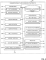
- FIG. 2 is a block diagram of an example AR enhancement apparatus 200 constructed in accordance with teachings of this disclosure.
- the AR enhancement apparatus 200 includes the example sensor array 102 (including the example depth sensor(s) 122 and the example motion sensor(s) 124) and the example projector 104 (including the example projection source 128 and the example projection controller 130) of FIG. 1 described above, and further includes an example sensor manager 202, an example map generator 204, an example object detector 206, an example object identifier 208, an example gesture detector 210, an example gesture identifier 212, an example target object determiner 214, an example enhancement determiner 216, an example user interface 218, and an example memory 220.
- the example user interface 218 of FIG. 2 includes one or more example input device(s) 226 and one or more example output device(s) 228.
- other example implementations of the AR enhancement apparatus 200 of FIG. 2 may include fewer or additional structures.
- the sensor array 102 (including the depth sensor(s) 122 and the motion sensor(s) 124), the projector 104 (including the projection source 128 and the projection controller 130), the sensor manager 202, the map generator 204, the object detector 206, the object identifier 208, the gesture detector 210, the gesture identifier 212, the target object determiner 214, the enhancement determiner 216 (including the context evaluator 222 and the physics simulator 224), the example user interface 218 (including the input device(s) 226 and the output device(s) 228), and/or the memory 220 are operatively coupled (e.g., in electrical communication) via an example communication bus 230.
- the sensor manager 202, the map generator 204, the object detector 206, the object identifier 208, the gesture detector 210, the gesture identifier 212, the target object determiner 214, the enhancement determiner 216, the context evaluator 222, and/or the physics simulator 224 of FIG. 2 may individually and/or collectively be implemented by any type(s) and/or any number(s) of semiconductor device(s) (e.g., microprocessors), microcontrollers), etc.).
- semiconductor device(s) e.g., microprocessors), microcontrollers
- the sensor array 102 may be integrated within, carried by, and/or mounted on the projector 104 of the AR enhancement apparatus 200 of FIG. 2 .
- the sensor array 102 may be located remotely from the projector 104.
- the sensor array 102 including the depth sensor(s) 122 and the motion sensor(s) 124) and may be located and/or positioned (e.g., mounted) on a boundary surface of a real environment (e.g., on the second wall 114 of the real environment 100 of FIG. 1 ).
- the sensor manager 202, the map generator 204, the object detector 206, the object identifier 208, the gesture detector 210, the gesture identifier 212, the target object determiner 214, the enhancement determiner 216 (including the context evaluator 222 and the physics simulator 224), the example user interface 218 (including the input device(s) 226 and the output device(s) 228), and/or the memory 220 of FIG. 2 may be integrated within, carried by, and/or mounted on the projector 104 of the AR enhancement apparatus 200 of FIG. 2 .
- the sensor manager 202, the map generator 204, the object detector 206, the object identifier 208, the gesture detector 210, the gesture identifier 212, the target object determiner 214, the enhancement determiner 216 (including the context evaluator 222 and the physics simulator 224), the example user interface 218 (including the input device(s) 226 and the output device(s) 228), and/or the memory 220 may be located remotely (e.g., via a cloud-based architecture) from the sensor array 102 and/or the projector 104.
- the sensor manager 202, the map generator 204, the object detector 206, the object identifier 208, the gesture detector 210, the gesture identifier 212, the target object determiner 214, the enhancement determiner 216 (including the context evaluator 222 and the physics simulator 224), the user interface 218 (including the input device(s) 226 and the output device(s) 228), and/or the memory 220 may be located remotely from a real environment (e.g., the real environment 100 of FIG. 1 ) in which the sensor array 102 and/or the projector 104 is/are located.
- a real environment e.g., the real environment 100 of FIG. 1
- the depth sensor(s) 122 of FIGS. 1 and 2 sense(s), measure(s) and/or detect(s) depth data (e.g., depths, distances, ranges, etc.) associated with a real environment (e.g., the real environment 100 of FIG. 1 ).
- the depth sensor(s) 122 can sense, measure and/or detect depth data associated with one or more boundary surface(s) (e.g., a ground surface, a floor, a ceiling, a wall, etc.) of the real environment, and/or one or more real object(s) (e.g., a whiteboard, a framed picture, a human, etc.) located within the real environment.
- Depth data sensed, measured and/or detected by the depth sensor(s) 122 may be associated with one or more local time(s) (e.g., time stamped) at which the data was collected by the depth sensor(s) 122.
- Depth data sensed, measured and/or detected by the depth sensor(s) 122 may be of any quantity, type, form and/or format, and may be stored in a computer-readable storage medium such as the example memory 220 of FIG. 2 described below.
- the motion sensor(s) 124 of FIGS. 1 and 2 sense(s), measure(s) and/or detect(s) motion data (e.g., movements, changes in position, changes in orientation, etc.) associated with a real environment (e.g., the real environment 100 of FIG. 1 ).
- the motion sensor(s) 124 can sense, measure and/or detect depth data associated with one or more real object(s) (e.g., a whiteboard, a framed picture, a human, etc.) located within the real environment.
- Motion data sensed, measured and/or detected by the motion sensor(s) 124 may be associated with one or more local time(s) (e.g., time stamped) at which the data was collected by the motion sensor(s) 124.
- Motion data sensed, measured and/or detected by the motion sensor(s) 124 may be of any quantity, type, form and/or format, and may be stored in a computer-readable storage medium such as the example memory 220 of FIG. 2 described below.
- the projector 104 of FIGS. 1 and 2 projects and/or displays one or more AR enhancement(s) (e.g., one or more AR extension(s) and/or object-intersecting AR content) to one or more real object(s) located and/or positioned within a real environment (e.g., the real environment 100 of FIG. 1 ).
- the projector 104 of FIGS. 1 and 2 may be implemented as a digital projector capable of projecting and/or displaying digital content (e.g., digital images and/or digital videos including textual and/or graphical information).
- the projector 104 of FIGS. 1 and 2 projects and/or displays one or more AR enhancement(s) via the example projection source 128 of FIGS. 1 and 2 .
- the projection source 128 may be implemented as a projection lens operatively coupled to and/or operatively aligned with a projection lamp.
- the projection controller 130 of FIGS. 1 and 2 controls the position and/or orientation of the projection source 128 and/or, more generally, the projector 104 of FIGS. 1 and 2 .
- the projection controller 130 may adjust, move and/or otherwise change the position and/or orientation of the projection source 128 from a current position and/or orientation to a target position and/or orientation to facilitate the projection of an AR enhancement to one or more real object(s) located within a real environment (e.g., the real environment 100 of FIG. 1 ).
- AR enhancements and/or AR enhancement data accessed, invoked, applied, processed and/or projected by the projection source 128 and the projection controller 130 and/or, more generally, by the projector 104 may be of any quantity, type, form and/or format, and may be stored in a computer-readable storage medium such as the example memory 220 of FIG. 2 described below.
- the example sensor manager 202 of FIG. 2 manages and/or controls the operation of the depth sensor(s) 122 and/or the motion sensor(s) 124 of the sensor array 102 of FIGS. 1 and 2 and/or, more generally, manages and/or controls the process of accessing and/or obtaining depth data and/or motion data.
- the sensor manager 202 may signal, command and/or instruct the depth sensor(s) 122 and/or the motion sensor(s) 124 to collect depth data and/or motion data at a specified time, and/or in response to the occurrence of a specified event.
- the sensor manager 202 of FIG. 2 signals, commands and/or instructs the depth sensor(s) 122 and /or the motion sensor(s) 124 of FIGS.
- Depth data and/or motion data accessed, obtained, received and/or processed by and/or at the sensor manager 202 may be of any quantity, type, form and/or format, and may be stored in a computer-readable storage medium such as the example memory 220 of FIG. 2 described below.
- the example map generator 204 of FIG. 2 generates a map of a real environment based on depth data associated with the real environment.
- the map generator 204 may generate a map (e.g., a three-dimensional spatial model) of the real environment 100 of FIG. 1 based on depth data obtained from the depth sensor(s) 122 of the sensor array 102 of FIGS. 1 and 2 .
- the map generated by the map generator 204 of FIG. 2 includes a representation of one or more boundary surface(s) of the real environment, and/or one or more real object(s) located and/or positioned within the real environment.
- map generated by the map generator 204 of FIG. 2 illustrates, provides and/or identifies relative locations and/or relative positions of respective ones of the boundary surface(s) and/or respective ones of the real object(s) within the real environment 100.
- Maps and/or map data generated and/or processed by and/or at the map generator 204 may be of any quantity, type, form and/or format, and may be stored in a computer-readable storage medium such as the example memory 220 of FIG. 2 described below.
- the example object detector 206 of FIG. 2 detects one or more real object(s) located in a real environment based on the map generated by the map generator 204 of FIG. 2 .
- the object detector 206 of FIG. 2 detects the one or more real object(s) located in the real environment by applying one or more object detection and/or computer vision algorithm(s) to the map of the real environment generated by the map generator 204 of FIG. 2 .
- the object detector 206 of FIG. 2 may detect one or more of the real object(s) (e.g., the first real object 116, the second real object 118, and/or the third real object 120 of FIG. 1 ) located in the real environment 100 of FIG. 1 by applying one or more object detection and/or computer vision algorithm(s) to the map of the real environment 100 of FIG. 1 generated by the map generator 204 of FIG. 2 .
- the object detection and/or computer vision algorithm(s) applied by the object detector 206 of FIG. 2 distinguish(es) real objects of the real environment represented by the map from boundary surfaces of the real environment represented by the map.
- the object detection and/or computer vision algorithm(s) applied by the object detector 206 of FIG. 2 may distinguish the real objects (e.g., the first real object 116, the second real object 118, and the third real object 120 of FIG. 1 ) of the real environment 100 of FIG. 1 represented by the map from the boundary surfaces (e.g., the floor 108, the ceiling 110, the first wall 112, and the second wall 114 of FIG. 1 ) of the real environment 100 of FIG. 1 represented by the map.
- the object detector 206 of FIG. 2 detects the real objects, but does not detect the boundary surfaces.
- the object detection and/or computer vision algorithm(s) applied by the object detector 206 of FIG. 2 additionally distinguish(es) non-human real objects of the real environment represented by the map from human real objects of the real environment represented by the map.
- the object detection and/or computer vision algorithm(s) applied by the object detector 206 of FIG. 2 may distinguish the non-human real objects (e.g., the first real object 116 and the second real object 118 of FIG. 1 ) of the real environment 100 of FIG. 1 represented by the map from the human real objects (e.g., the third real object 120 of FIG. 1 ) of the real environment 100 of FIG. 1 represented by the map.
- Object detection data, object detection algorithms, and/or computer vision algorithms accessed, implemented, invoked, applied, detected and/or processed by and/or at the object detector 206 may be of any quantity, type, form and/or format, and may be stored in a computer-readable storage medium such as the example memory 220 of FIG. 2 described below.
- the example object identifier 208 of FIG. 2 semantically identifies the real object(s) detected by the object detector 206 of FIG. 2 .
- the object identifier 208 of FIG. 2 semantically identifies (e.g., labels, tags, and/or classifies) respective ones of the real object(s) detected by the object detector 206 of FIG. 2 by applying a semantic identification algorithm to the real object(s) detected by the object detector 206 of FIG. 2 as represented by the map generated by the map generator 204 of FIG. 2 .
- the semantic identification algorithm(s) applied by the object identifier 208 of FIG. 2 may semantically identify the first real object 116 of FIG. 1 as a whiteboard, the second real object 118 of FIG. 1 as a framed picture, and/or the third real object 120 of FIG. 1 as a human and/or user.
- the semantic identification algorithm(s) applied by the object identifier 208 of FIG. 2 may semantically identify the first real object 116 of FIG. 1 as a whiteboard, the second real object 118 of FIG. 1 as a framed picture, and/or the third real object 120 of FIG. 1 as a human and/or user.
- Semantic identification data and/or semantic identification algorithms accessed, implemented, invoked, applied, generated and/or processed by and/or at the object identifier 208 may be of any quantity, type, form and/or format, and may be stored in a computer-readable storage medium such as the example memory 220 of FIG. 2 described below.
- the example gesture detector 210 of FIG. 2 detects one or more occurrence(s) of one or more user gesture(s) within a real environment based on motion data associated with the real environment.
- the gesture detector 210 may detect one or more occurrence(s) of one or more user gesture(s) (e.g., one or more hand, arm, foot or leg gesture(s) made by a human) within the real environment 100 of FIG. 1 based on motion data generated by and obtained from the motion sensor(s) 124 of the sensor array 102 of FIGS. 1 and 2 .
- the gesture detector 210 of FIG. 2 may detect the occurrence(s) of the user gesture(s) within the real environment 100 of FIG. 1 by applying one or more object detection and/or computer vision algorithm(s) to the motion data obtained from the motion sensor(s) 124 of the sensor array 102 of FIGS. 1 and 2 .
- the movement recognition and/or computer vision algorithm(s) applied by the gesture detector 210 of FIG. 2 distinguish(es) human movements (e.g., user gestures) from non-human movements (e.g., non-human real object movements).
- the movement recognition and/or computer vision algorithm(s) applied by the gesture detector 210 of FIG. 2 may distinguish a movement of the third real object 120 (e.g., a movement of the hand 134 of the human corresponding to the third real object 120) of FIG. 1 from a movement of the second real object 118 (e.g., a movement of the framed picture corresponding to the second real object 118) of FIG. 1 .
- User gesture detection data, movement recognition algorithms, and/or computer vision algorithms accessed, implemented, invoked, applied, detected and/or processed by and/or at the object detector 206 may be of any quantity, type, form and/or format, and may be stored in a computer-readable storage medium such as the example memory 220 of FIG. 2 described below.
- the example gesture identifier 212 of FIG. 2 semantically identifies the user gesture(s) detected by the gesture detector 210 of FIG. 2 .
- the gesture identifier 212 of FIG. 2 semantically identifies (e.g., labels, tags, and/or classifies) respective ones of the user gesture(s) detected by the gesture detector 210 of FIG. 2 by applying one or more semantic identification algorithm(s) to the user gesture(s).
- the gesture identifier 212 of FIG. 2 may apply one or more semantic identification algorithm(s) to the user gesture(s) detected by the gesture detector 210 of FIG. 2 as occurring within the real environment 100 of FIG. 1 .
- semantic identification algorithm(s) applied by the gesture identifier 212 of FIG. 2 may further semantically identify one or more physical boundaries and/or physical properties (e.g., a size, a shape, an edge, a contour, etc.) of respective ones of the user gesture(s).
- Semantic identification data and/or semantic identification algorithms accessed, implemented, invoked, applied, generated and/or processed by and/or at the gesture identifier 212 may be of any quantity, type, form and/or format, and may be stored in a computer-readable storage medium such as the example memory 220 of FIG. 2 described below.
- the example target object determiner 214 of FIG. 2 determines one or more target real object(s) associated with the user gesture(s) detected by the gesture detector 210 of FIG. 2 based on the user gesture(s), and further based on the map of the real environment generated by the map generator 204 of FIG. 2 and/or the real object(s) detected by the object detector 206 of FIG. 2 .
- the target object determiner 214 of FIG. 2 may determine a target real object associated with a user gesture detected by the gesture detector 210 of FIG. 2 based the user gesture, and further based on the map of the real environment 100 of FIG. 1 generated by the map generator 204 of FIG. 2 and/or the real object(s) detected by the object detector 206 of FIG. 2 .
- the target object determiner 214 of FIG. 2 determines a target real object associated with a user gesture from among the real object(s) represented by the map generated by the map generator 204 of FIG. 2 and/or detected by the object detector 206 of FIG. 2 by identifying the target real object as the one of the real object(s) (e.g., the one of the non-human real object(s)) that is most proximate relative to the user gesture.
- the target object determiner 214 of FIG. 2 may determine, based on the user gesture, and further based on the map of the real environment 100 of FIG. 1 generated by the map generator 204 of FIG. 2 and/or the real object(s) detected by the object detector 206 of FIG.
- the target object determiner 214 of FIG. 2 identifies the second real object 118 as the target real object associated with the user gesture.
- Target object data determined, generated and/or processed by and/or at the target object determiner 214 may be of any quantity, type, form and/or format, and may be stored in a computer-readable storage medium such as the example memory 220 of FIG. 2 described below.
- the example enhancement determiner 216 of FIG. 2 determines one or more AR enhancement(s) (e.g., AR extension(s) and/or object-intersecting AR content) based on the user gesture(s) detected by the gesture detector 210 of FIG. 2 and the target real object(s) determined by the target object determiner 214 of FIG. 2 .
- the enhancement determiner 216 of FIG. 2 determines the AR enhancement(s) by implementing, invoking and/or applying an AR enhancement model structured as a set of semantic rules that are configured to guide interactions and/or relationships between AR enhancement(s) associated with the user gesture(s) on the one hand, and the target real object(s) associated with the user gesture(s) on the other hand.
- the user gesture(s) and the target real object(s) are inputs to the AR enhancement model.
- the AR enhancement model further incorporates the map generated by the map generator 204 of FIG. 2 , the real object(s) detected by the object detector 206 of FIG. 2 , the semantic identification(s) of the real object(s) generated (e.g., semantically identified) by the object identifier 208 of FIG. 2 , and/or the semantic identification(s) of the user gesture(s) generated (e.g., semantically identified) by the gesture identifier 212 of FIG. 2 as inputs to the AR enhancement model.
- the AR enhancement model implemented, invoked and/or applied by the enhancement determiner 216 of FIG. 2 determines and/or outputs one or more AR enhancement(s) based on the specific content of the inputs described above.
- the AR enhancement(s) determined by the enhancement determiner 216 of FIG. 2 include(s) at least one of a virtual resizing of a target real object, a virtual structure associated with (e.g., intersecting) a target real object, or a virtual character associated with (e.g., intersecting) a target real object. Examples of AR enhancements determined by the enhancement determiner 216 of FIG. 2 are further described below in connection with FIGS. 3A-3B , 4A-4C , 5A-5C , 6A-6D and 7A-7B .
- the enhancement determiner 216 of FIG. 2 includes the context evaluator 222 and the physics simulator 224 of FIG. 2 , each of which is further described below.
- the context evaluator 222 and the physics simulator 224 of the enhancement determiner 216 of FIG. 2 are respectively implemented as part of the set of semantic rules which form the AR enhancement model that is implemented, invoked and/or applied by the enhancement determiner 216 of FIG. 2 .
- the context evaluator 222 and the physics simulator 224 of the enhancement determiner 216 of FIG. 2 are respectively configured to guide interactions and/or relationships between AR enhancement(s) associated with the user gesture(s) on the one hand, and the target real object(s) associated with the user gesture(s) on the other hand.
- the example context evaluator 222 of FIG. 2 evaluates contextual information associated with the user gesture(s) detected by the gesture detector 210 of FIG. 2 , and/or associated with the target real object(s) determined by the target object determiner 214 of FIG. 2 .
- the contextual information evaluated by the context evaluator 222 of FIG. 2 includes one or more portion(s) (including all) of the semantic identification(s) of the real object(s) generated (e.g., semantically identified) by the object identifier 208 of FIG. 2 , and/or one or more portion(s) (including all) of the semantic identification(s) of the user gesture(s) generated (e.g., semantically identified) by the gesture identifier 212 of FIG. 2 .
- the context evaluator 222 of FIG. 2 may evaluate one or more physical boundaries and/or physical properties (e.g., a size, a shape, a color, an edge, a contour, a texture, etc.) of the user gesture(s) and/or of the target real object(s).
- the context evaluator 222 of FIG. 2 may additionally or alternatively evaluate one or more physical boundaries and/or physical properties associated with the map generated by the map generator 204 of FIG. 2 .
- the contextual evaluation(s) performed by the of context evaluator 222 of FIG. 2 evaluate(s) possible and/or probable contextual interactions between the user gesture(s), the target real object(s), and/or one or more potential (e.g., candidate) AR enhancement(s), and guide(s) the enhancement determiner 216 of FIG. 2 in determining a specific one of the potential (e.g., candidate) AR enhancement(s). For example, the enhancement determiner 216 of FIG.
- a specific AR enhancement e.g., an AR enhancement having a specific type, size, shape, color, orientation and/or location
- Contextual information accessed, implemented, invoked, applied, evaluated, generated and/or processed by and/or at the context evaluator 222 may be of any quantity, type, form and/or format, and may be stored in a computer-readable storage medium such as the example memory 220 of FIG. 2 described below.
- the example physics simulator 224 of FIG. 2 simulates physics associated with the user gesture(s) detected by the gesture detector 210 of FIG. 2 , and/or associated with the target real object(s) determined by the target object determiner 214 of FIG. 2 .
- the physics simulated by the physics simulator 224 of FIG. 2 may be based on one or more portion(s) (including all) of the semantic identification(s) of the real object(s) generated (e.g., semantically identified) by the object identifier 208 of FIG. 2 , and/or one or more portion(s) (including all) of the semantic identification(s) of the user gesture(s) generated (e.g., semantically identified) by the gesture identifier 212 of FIG. 2 .
- the physics simulator 224 of FIG. 2 may evaluate one or more physical boundaries and/or physical properties (e.g., a size, a shape, an edge, a contour, a texture, an orientation, a location, etc.) of the user gesture(s) and/or of the target real object(s).
- the physics simulator 224 of FIG. 2 may additionally or alternatively evaluate one or more physical boundaries and/or physical properties associated with the map generated by the map generator 204 of FIG. 2 .
- the physics simulation(s) performed by the of physics simulator 224 of FIG. 2 simulate(s) possible and/or probable physical interactions and/or relationships between the user gesture(s), the target real object(s), and/or one or more potential (e.g., candidate) AR enhancement(s), and guide(s) the enhancement determiner 216 of FIG. 2 in identifying, selecting and/or determining a specific one of the potential (e.g., candidate) AR enhancement(s).
- a specific AR enhancement e.g., an AR enhancement having a specific type, size, shape, orientation and/or location
- Physics data accessed, implemented, invoked, applied, simulated, generated and/or processed by and/or at the physics simulator 224 may be of any quantity, type, form and/or format, and may be stored in a computer-readable storage medium such as the example memory 220 of FIG. 2 described below.
- the enhancement determiner 216 of FIG. 2 commands a projector located within a real environment to project the AR enhancement(s) to the target real object(s).
- the enhancement determiner 216 of FIG. 2 may command, instruct, and/or signal the projection source 128, the projection controller 130 and/or, more generally, the projector 104 of FIGS. 1 and 2 located within the real environment 100 of FIG. 1 in a manner that causes the projection source 128, the projection controller 130 and/or, more generally, the projector 104 of FIGS. 1 and 2 to project the AR enhancement(s), as determined by the enhancement determiner 216 of FIG. 2 , to the target real object(s) located within the real environment 100 of FIG. 1 .
- AR enhancement data and/or the AR enhancement model accessed, implemented, invoked, applied, generated and/or processed by and/or at the enhancement determiner 216 may be of any quantity, type, form and/or format, and may be stored in a computer-readable storage medium such as the example memory 220 of FIG. 2 described below.
- the example user interface 218 of FIG. 2 facilitates interactions and/or communications between an end user and the AR enhancement apparatus 200.
- the user interface 218 includes one or more input device(s) 226 via which the user may input information and/or data to the AR enhancement apparatus 200.
- the input device(s) 226 may include a button, a switch, a microphone, and/or a touchscreen that enable(s) the user to convey data and/or commands to the sensor array 102, the projector 104, the sensor manager 202, the map generator 204, the object detector 206, the object identifier 208, the gesture detector 210, the gesture identifier 212, the target object determiner 214, the enhancement determiner 216, the memory 220, the context evaluator 222, and/or the physics simulator 224 of FIG.
- the user interface 218 of FIG. 2 also includes one or more output device(s) 228 via which the user interface 218 presents information and/or data in visual and/or audible form to the user.
- the output device(s) 228 may include a light emitting diode, a touchscreen, and/or a liquid crystal display for presenting visual information, and/or a speaker for presenting audible information.
- the output device(s) 228 can be implemented by and/or as one or more AR output device(s) (e.g., an AR headset, AR glasses, etc.).
- Data and/or information that is presented and/or received via the user interface 218 may be of any quantity, type, form and/or format, and may be stored in a computer-readable storage medium such as the example memory 220 of FIG. 2 described below.
- the example memory 220 of FIG. 2 may be implemented by any type(s) and/or any number(s) of storage device(s) such as a storage drive, a flash memory, a read-only memory (ROM), a random-access memory (RAM), a cache and/or any other physical storage medium in which information is stored for any duration (e.g., for extended time periods, permanently, brief instances, for temporarily buffering, and/or for caching of the information).
- the information stored in the memory 220 may be stored in any file and/or data structure format, organization scheme, and/or arrangement.
- the memory 220 stores depth data sensed, measured and/or detected by the depth sensor(s) 122 of FIGS. 1 and 2 . In some examples, the memory 220 stores motion data sensed, measured and/or detected by the motion sensor(s) 124 of FIGS. 1 and 2 . In some examples, the memory 220 stores depth data and/or motion data accessed, obtained, received and/or processed by and/or at the sensor manager 202 of FIG. 2 . In some examples, the memory 220 stores maps and/or map data generated and/or processed by and/or at the map generator 204 of FIG. 2 .
- the memory 220 stores object detection data, object detection algorithms, and/or computer vision algorithms accessed, implemented, invoked, applied, detected and/or processed by and/or at the object detector 206 of FIG. 2 .
- the memory 220 stores semantic identification data and/or semantic identification algorithms accessed, implemented, invoked, applied, generated and/or processed by and/or at the object identifier 208 of FIG. 2 .
- the memory 220 stores user gesture detection data, movement recognition algorithms, and/or computer vision algorithms accessed, implemented, invoked, applied, detected and/or processed by and/or at the gesture detector 210 of FIG. 2 .
- the memory 220 stores semantic identification data and/or semantic identification algorithms accessed, implemented, invoked, applied, generated and/or processed by and/or at the gesture identifier 212 of FIG. 2 .
- the memory 220 stores target object data determined, generated and/or processed by and/or at the target object determiner 214 of FIG. 2 .
- the memory 220 stores AR enhancement data and/or AR enhancement models accessed, implemented, invoked, applied, generated and/or processed by and/or at the enhancement determiner 216 of FIG. 2 .
- the memory 220 stores contextual information accessed, implemented, invoked, applied, evaluated, generated and/or processed by and/or at the context evaluator 222 of FIG. 2 .
- the memory 220 stores physics data accessed, implemented, invoked, applied, simulated, generated and/or processed by and/or at the physics simulator 224 of FIG. 2 . In some examples, the memory 220 stores data and/or information that is presented and/or received via the user interface 218 of FIG. 2 .
- the memory 220 of FIG. 2 is accessible to the sensor array 102 (including the depth sensor(s) 122 and the motion sensor(s) 124), the projector 104 (including the projection source 128 and the projection controller 130), the sensor manager 202, the map generator 204, the object detector 206, the object identifier 208, the gesture detector 210, the gesture identifier 212, the target object determiner 214, the enhancement determiner 216 (including the context evaluator 222 and the physics simulator 224), and/or the user interface 218 (including the input device(s) 226 and the output device(s) 228) of FIG. 2 , and/or, more generally, to the AR enhancement apparatus 200 of FIG. 2 .
- the sensor array 102 of FIGS. 1 and 2 is structured to sense, measure and/or detect depth data and/or motion data associated with a real environment.
- the depth sensor(s) 122 of FIGS. 1 and 2 is/are structured to sense, measure and/or detect depth data associated with a real environment.
- the motion sensor(s) 124 of FIGS. 1 and 2 is/are structured to sense, measure and/or detect motion data associated with a real environment.
- the projector 104 of FIGS. 1 and 2 is structured to project one or more AR enhancements in a real environment.
- the projection source 128 of FIGS. 1 and 2 is structured to project one or more AR enhancements from the projector 104 of FIGS. 1 and 2 .
- the projection controller 130 of FIGS. 1 and 2 is structured to control an orientation of the projection source 128 and/or the projector 104 of FIGS. 1 and 2 within a real environment.
- the sensor manager 202 of FIG. 2 is structured to obtain depth data and/or motion data from the depth sensor(s) 122 and/or the motion sensor(s) 124 of FIGS. 1 and 2 and/or, more generally, from the sensor array 102 of FIGS. 1 and 2 .
- the map generator 204 of FIG. 2 is structured to generate a map of a real environment based on depth data obtained from the depth sensor(s) 122 of FIGS. 1 and 2 and/or, more generally, from the sensor array 102 of FIGS. 1 and 2 .
- the object detector 206 of FIG. 2 is structured to detect one or more real object(s) based on the map generated by the map generator 204 of FIG. 2 .
- the gesture detector 210 of FIG. 2 is structured to detect one or more user gesture(s) based on motion data generated by and obtained from the motion sensor(s) 124 of FIGS. 1 and 2 and/or, more generally, from the sensor array 102 of FIGS. 1 and 2 .
- the gesture identifier 212 of FIG. 2 is structured to semantically identify the user gesture(s) detected by the gesture detector 210 of FIG. 2 .
- the target object determiner 214 of FIG. 2 is structured to determine one or more target real object(s) associated with the user gesture(s) detected by the gesture detector 210 of FIG. 2 .
- the enhancement determiner 216 of FIG. 2 is structured to determine one or more AR enhancement(s) based on the user gesture(s) detected by the gesture detector 210 of FIG. 2 and the associated target real object(s) determined by the target object determiner 214 of FIG. 2 .
- the context evaluator 222 of FIG. 2 is structured to evaluate contextual information associated with the user gesture(s) detected by the gesture detector 210 of FIG. 2 and/or the associated target real object(s) determined by the target object determiner 214 of FIG. 2 .
- the physics simulator 224 of FIG. 2 is structured to simulate physics associated with the user gesture(s) detected by the gesture detector 210 of FIG. 2 and the associated target real object(s) determined by the target object determiner 214 of FIG. 2 .
- the user interface 218 of FIG. 2 is structured to facilitate interactions and/or communications between an end user and the AR enhancement apparatus 200 of FIG. 2 .
- the input device(s) 226 of FIG. 2 is/are structured to input information and/or data to the AR enhancement apparatus 200 of FIG. 2 .
- the output device(s) 228 of FIG. 2 is/are structured to present information and/or data in visual and/or audible form via the AR enhancement apparatus 200 of FIG. 2 .
- the memory 220 of FIG. 2 is structured to store data, information, algorithms and/or models detected, identified, determined, generated, accessed, implemented, invoked, applied and/or processed by the AR enhancement apparatus 200 of FIG. 2 and/or any of the components thereof.
- FIGS. 3A and 3B illustrate a first example of the AR enhancement apparatus 200 of FIG. 2 projecting an AR enhancement to a real object located within a real environment in response to an occurrence of a user gesture detected in the real environment.
- an example real environment 300 includes an example real object 302 (e.g., a framed picture) located and/or positioned (e.g., mounted) on an example wall 304 of the real environment 300.
- an example user gesture 306 represented as a dashed line
- an example hand 308 of a human e.g., a user
- the map generator 204 of FIG. 2 generates a map of the real environment 300
- the object detector 206 of FIG. 2 detects the real object 302
- the object identifier 208 of FIG. 2 semantically identifies the real object 302 as a framed picture.
- the gesture detector 210 of FIG. 2 detects the user gesture 306, the gesture identifier 212 of FIG. 2 semantically identifies the user gesture 306 as a touch input indicative of a request to resize (e.g., enlarge or expand) the real object 302, and the target object determiner 214 of FIG. 2 determines that the real object 302 is the target real object.
- the AR enhancement 310 is projected on the wall 304 of the real environment 300 as an enhancement and/or extension to the real object 302, with the AR enhancement 310 being projected as a resizing (e.g., expansion and/or extension) of the real object 302 that intersects the real object 302.
- FIGS. 4A, 4B and 4C illustrate a second example of the AR enhancement apparatus 200 of FIG. 2 projecting an AR enhancement to a real object located within a real environment in response to an occurrence of a user gesture detected in the real environment.
- an example real environment 400 includes an example real object 402 (e.g., a framed picture) located and/or positioned (e.g., mounted) on an example wall 404 of the real environment 400.
- an example user gesture 406 represented as a dashed line
- an example hand 408 of a human e.g., a user
- the map generator 204 of FIG. 2 generates a map of the real environment 400
- the object detector 206 of FIG. 2 detects the real object 402
- the object identifier 208 of FIG. 2 semantically identifies the real object 402 as a framed picture.
- the gesture detector 210 of FIG. 2 detects the user gesture 406, the gesture identifier 212 of FIG. 2 semantically identifies the user gesture 406 as a virtual drawing indicative of a request to add steps extending away from the real object 402, and the target object determiner 214 of FIG. 2 determines that the real object 402 is the target real object.
- the second AR enhancement 412 is projected on the wall 404 of the real environment 400 as an enhancement and/or extension to the first AR enhancement 410 and/or the real object 402, with the second AR enhancement 412 being projected as a character (e.g., a kangaroo) that intersects the first AR enhancement 410.
- a character e.g., a kangaroo
- FIGS. 5A, 5B and 5C illustrate a third example of the AR enhancement apparatus 200 of FIG. 2 projecting an AR enhancement to a real object located within a real environment in response to an occurrence of a user gesture detected in the real environment.
- an example real environment 500 includes an example real object 502 (e.g., a framed picture) located and/or positioned (e.g., mounted) on an example wall 504 of the real environment 500.
- an example user gesture 506 represented as a dashed line
- an example hand 508 of a human e.g., a user
- the map generator 204 of FIG. 2 generates a map of the real environment 500
- the object detector 206 of FIG. 2 detects the real object 502
- the object identifier 208 of FIG. 2 semantically identifies the real object 502 as a framed picture.
- the gesture detector 210 of FIG. 2 detects the user gesture 506, the gesture identifier 212 of FIG. 2 semantically identifies the user gesture 506 as a virtual drawing indicative of a request to add a ramp extending away from the real object 502, and the target object determiner 214 of FIG. 2 determines that the real object 502 is the target real object.
- the second AR enhancement 512 is projected on the wall 504 of the real environment 500 as an enhancement and/or extension to the first AR enhancement 510 and/or the real object 502, with the second AR enhancement 512 being projected as a character (e.g., a toy jeep) that intersects the first AR enhancement 510.
- a character e.g., a toy jeep
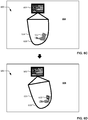
- FIGS. 6A, 6B , 6C and 6D illustrate a fourth example of the AR enhancement apparatus 200 of FIG. 2 projecting an AR enhancement to a real object located within a real environment in response to an occurrence of a user gesture detected in the real environment.
- an example real environment 600 includes an example real object 602 (e.g., a framed picture) located and/or positioned (e.g., mounted) on an example wall 604 of the real environment 600.
- an example user gesture 606 represented as a dashed line
- an example hand 608 of a human e.g., a user
- the map generator 204 of FIG. 2 generates a map of the real environment 600
- the object detector 206 of FIG. 2 detects the real object 602
- the object identifier 208 of FIG. 2 semantically identifies the real object 602 as a framed picture.
- the gesture detector 210 of FIG. 2 detects the user gesture 606, the gesture identifier 212 of FIG. 2 semantically identifies the user gesture 606 as a virtual drawing indicative of a request to add a movable (e.g., swingable) platform extending downwardly from the real object 602, and the target object determiner 214 of FIG. 2 determines that the real object 602 is the target real object.
- a movable e.g., swingable
- the enhancement determiner 216 of FIG. 2 has determined a first example AR enhancement 610 and a second example AR enhancement 612, and has commanded a projector to respectively project the first AR enhancement 610 and the second AR enhancement 612.
- the first AR enhancement 610 is projected on the wall 604 of the real environment 600 as an enhancement and/or extension to the real object 602, with the first AR enhancement 610 being projected as a movable (e.g., swingable) platform that intersects the real object 602.
- a movable e.g., swingable
- the second AR enhancement 612 is projected on the wall 604 of the real environment 600 as an enhancement and/or extension to the first AR enhancement 610 and/or the real object 602, with the second AR enhancement 612 being projected as a character (e.g., a bird) that intersects the first AR enhancement 610.
- a character e.g., a bird
- the first AR enhancement 610 is projected on the wall 604 of the real environment 600 in a first example orientation and/or position 614.
- the first AR enhancement 610 is projected on the wall 604 of the real environment 600 in a second example orientation and/or position 616 that differs from the first example orientation and/or position 614 of the first AR enhancement 610 shown in FIG. 6C .
- FIG. 6D results from the interaction of the second AR enhancement 612 with the first AR enhancement 610, as determined by the context evaluator 222 and/or the physics simulator 224 of the enhancement determiner 216 of FIG. 2 .
- movement of the first AR enhancement 610 may be governed by contextual information and/or simulated physics associated with the first AR enhancement 610 relative to the real object 602, and/or by contextual information and/or simulated physics associated with the second AR enhancement 612 relative to the first AR enhancement 610.
- FIGS. 7A and 7B illustrate a fifth example of the AR enhancement apparatus 200 of FIG. 2 projecting an AR enhancement to a real object located within a real environment in response to an occurrence of a user gesture detected in the real environment.
- an example real environment 700 includes an example real object 702 (e.g., a whiteboard) located and/or positioned (e.g., mounted) on an example wall 704 of the real environment 700.
- an example user gesture 706 (corresponding to an aspect or segment of an example physical drawing 708) made by an example marking device 710 held by an example hand 712 of a human (e.g., a user) has been made on the real object 702.
- the map generator 204 of FIG. 2 generates a map of the real environment 700
- the object detector 206 of FIG. 2 detects the real object 702
- the object identifier 208 of FIG. 2 semantically identifies the real object 702 as a whiteboard.
- the gesture detector 210 of FIG. 2 detects the user gesture 706, the gesture identifier 212 of FIG. 2 semantically identifies the user gesture 706 as a segment of a physical drawing indicative of a tree branch added to a tree, and the target object determiner 214 of FIG. 2 determines that the real object 702 is the target real object.
- the AR enhancement 714 is projected on the real object 702 of the real environment 700 as an enhancement and/or extension to the physical drawing 708 that has been made on the real object 702, with the AR enhancement 714 being projected as a character (e.g., a bird) that intersects the physical drawing 708 that has been made on the real object 702.
- a character e.g., a bird
- While an example manner of implementing the AR enhancement apparatus 200 is illustrated in FIG. 2 , one or more of the elements, processes and/or devices illustrated in FIG. 2 may be combined, divided, re-arranged, omitted, eliminated and/or implemented in any other way.
- programmable logic device(s) PLD(s)
- FPLD field programmable logic device
- a non-transitory computer readable storage device or storage disk such as a memory, a digital versatile disk (DVD), a compact disk (CD), a Blu-ray disk, etc. including the software and/or firmware.
- the phrase "in communication,” including variations thereof, encompasses direct communication and/or indirect communication through one or more intermediary component(s), and does not require direct physical (e.g., wired) communication and/or constant communication, but rather additionally includes selective communication at periodic intervals, scheduled intervals, aperiodic intervals, and/or one-time events.
- FIGS. 8 and 9 Flowcharts representative of example hardware logic, machine readable instructions, hardware implemented state machines, and/or any combination thereof for implementing the AR enhancement apparatus 200 of FIG. 2 are shown in FIGS. 8 and 9 .
- the machine readable instructions may be one or more executable program(s) or portion(s) of executable program(s) for execution by a computer processor such as the example processor 1002 shown in the example processor platform 1000 discussed below in connection with FIG. 10 .
- the program(s) may be embodied in software stored on a non-transitory computer readable storage medium such as a CD-ROM, a floppy disk, a hard drive, a DVD, a Blu-ray disk, or a memory associated with the processor 1002, but the entire program(s) and/or parts thereof could alternatively be executed by a device other than the processor 1002 and/or embodied in firmware or dedicated hardware.
- a non-transitory computer readable storage medium such as a CD-ROM, a floppy disk, a hard drive, a DVD, a Blu-ray disk, or a memory associated with the processor 1002, but the entire program(s) and/or parts thereof could alternatively be executed by a device other than the processor 1002 and/or embodied in firmware or dedicated hardware.
- the example program(s) is/are described with reference to the flowcharts illustrated in FIGS. 8 and 9 , many other methods of implementing the example AR enhancement apparatus 200 of FIG. 2 may alternatively be used. For example
- any or all of the blocks may be implemented by one or more hardware circuit(s) (e.g., discrete and/or integrated analog and/or digital circuitry, an FPGA, an ASIC, a comparator, an operational-amplifier (op-amp), a logic circuit, etc.) structured to perform the corresponding operation without executing software or firmware.
- hardware circuit(s) e.g., discrete and/or integrated analog and/or digital circuitry, an FPGA, an ASIC, a comparator, an operational-amplifier (op-amp), a logic circuit, etc.
- the machine readable instructions described herein may be stored in one or more of a compressed format, an encrypted format, a fragmented format, a packaged format, etc.
- Machine readable instructions as described herein may be stored as data (e.g., portions of instructions, code, representations of code, etc.) that may be utilized to create, manufacture, and/or produce machine executable instructions.
- the machine readable instructions may be fragmented and stored on one or more storage device(s) and/or computing device(s) (e.g., servers).
- the machine readable instructions may require one or more of installation, modification, adaptation, updating, combining, supplementing, configuring, decryption, decompression, unpacking, distribution, reassignment, etc.
- the machine readable instructions may be stored in multiple parts, which are individually compressed, encrypted, and stored on separate computing devices, wherein the parts when decrypted, decompressed, and combined form a set of executable instructions that implement a program such as that described herein.
- the machine readable instructions may be stored in a state in which they may be read by a computer, but require addition of a library (e.g., a dynamic link library (DLL)), a software development kit (SDK), an application programming interface (API), etc. in order to execute the instructions on a particular computing device or other device.
- a library e.g., a dynamic link library (DLL)
- SDK software development kit
- API application programming interface
- the machine readable instructions may need to be configured (e.g., settings stored, data input, network addresses recorded, etc.) before the machine readable instructions and/or the corresponding program(s) can be executed in whole or in part.
- the disclosed machine readable instructions and/or corresponding program(s) are intended to encompass such machine readable instructions and/or program(s) regardless of the particular format or state of the machine readable instructions and/or program(s) when stored or otherwise at rest or in transit.
- FIGS. 8 and 9 may be implemented using executable instructions (e.g., computer and/or machine readable instructions) stored on a non-transitory computer and/or machine readable medium such as a hard disk drive, a flash memory, a read-only memory, a compact disk, a digital versatile disk, a cache, a random-access memory and/or any other storage device or storage disk in which information is stored for any duration (e.g., for extended time periods, permanently, for brief instances, for temporarily buffering, and/or for caching of the information).
- a non-transitory computer readable medium is expressly defined to include any type of computer readable storage device and/or storage disk and to exclude propagating signals and to exclude transmission media.
- A, B, and/or C refers to any combination or subset of A, B, C such as (1) A alone, (2) B alone, (3) C alone, (4) A with B, (5) A with C, (6) B with C, and (7) A with B and with C.
- the phrase "at least one of A and B" is intended to refer to implementations including any of (1) at least one A, (2) at least one B, and (3) at least one A and at least one B.
- the phrase "at least one of A or B" is intended to refer to implementations including any of (1) at least one A, (2) at least one B, and (3) at least one A and at least one B.
- the phrase "at least one of A and B" is intended to refer to implementations including any of (1) at least one A, (2) at least one B, and (3) at least one A and at least one B.
- the phrase "at least one of A or B" is intended to refer to implementations including any of (1) at least one A, (2) at least one B, and (3) at least one A and at least one B.
- FIG. 8 is a flowchart representative of example machine readable instructions 800 that may be executed to implement the example AR enhancement apparatus 200 of FIG. 2 to project an AR enhancement to a real object located within a real environment in response to a user gesture detected in the real environment.
- the example program 800 of FIG. 8 begins when the example sensor manager 202 of FIG. 2 obtains depth data associated with a real environment (block 802).
- the sensor manager 202 may signal, command and/or instruct the depth sensor(s) 122 of the sensor array 102 of FIGS. 1 and 2 to collect depth data associated with the real environment 100 of FIG. 1 at a specified time, and/or in response to the occurrence of a specified event.
- the depth sensor(s) 122 of the sensor array 102 of FIGS. 1 and 2 signals, commands and/or instructs the depth sensor(s) 122 of the sensor array 102 of FIGS. 1 and 2 to collect depth data associated with the real environment 100 of FIG. 1 in response to one or more user input(s) received via the user interface 218 of FIG. 2 .
- the example map generator 204 of FIG. 2 generates a map of the real environment based on the depth data.
- the map generator 204 may generate a map (e.g., a three-dimensional spatial model) of the real environment 100 of FIG. 1 based on depth data obtained from the depth sensor(s) 122 of the sensor array 102 of FIGS. 1 and 2 .
- the map generated by the map generator 204 of FIG. 2 includes a representation of one or more boundary surface(s) of the real environment, and/or one or more real object(s) located and/or positioned within the real environment.
- the map generated by the map generator 204 of FIG. 2 illustrates, provides and/or identifies relative locations and/or relative positions of respective ones of the boundary surface(s) and/or respective ones of the real object(s) within the real environment 100.
- the example object detector 206 of FIG. 2 detects one or more real object(s) located in the real environment based on the map.
- the object detector 206 of FIG. 2 detects the one or more real object(s) located in the real environment by applying an object detection algorithm to the map of the real environment generated by the map generator 204 of FIG. 2 .
- the object detector 206 of FIG. 2 may detect one or more of the real object(s) (e.g., the first real object 116, the second real object 118, and/or the third real object 120 of FIG. 1 ) located in the real environment 100 of FIG. 1 by applying an object detection algorithm to the map of the real environment 100 of FIG. 1 generated by the map generator 204 of FIG. 2 .
- the object detection algorithm applied by the object detector 206 of FIG. 2 distinguishes real objects of the real environment represented by the map from boundary surfaces of the real environment represented by the map.
- the object detection algorithm applied by the object detector 206 of FIG. 2 may distinguish the real objects (e.g., the first real object 116, the second real object 118, and the third real object 120 of FIG. 1 ) of the real environment 100 of FIG. 1 represented by the map from the boundary surfaces (e.g., the floor 108, the ceiling 110, the first wall 112, and the second wall 114 of FIG. 1 ) of the real environment 100 of FIG. 1 represented by the map.
- the object detector 206 of FIG. 2 detects the real objects, but does not detect the boundary surfaces.
- the object detection algorithm applied by the object detector 206 of FIG. 2 additionally distinguishes non-human real objects of the real environment represented by the map from human real objects of the real environment represented by the map.
- the object detection algorithm applied by the object detector 206 of FIG. 2 may distinguish the non-human real objects (e.g., the first real object 116 and the second real object 118 of FIG. 1 ) of the real environment 100 of FIG. 1 represented by the map from the human real objects (e.g., the third real object 120 of FIG. 1 ) of the real environment 100 of FIG. 1 represented by the map.
- the object detector 206 of FIG. 2 detects the non-human real objects, but does not detect the human real objects.
- the example object identifier 208 of FIG. 2 semantically identifies the detected real object(s).
- the object identifier 208 of FIG. 2 semantically identifies (e.g., labels, tags, and/or classifies) respective ones of the real object(s) detected by the object detector 206 of FIG. 2 by applying a semantic identification algorithm to the real object(s) detected by the object detector 206 of FIG. 2 as represented by the map generated by the map generator 204 of FIG. 2 .
- the semantic identification algorithm applied by the object identifier 208 of FIG. 2 may semantically identify the first real object 116 of FIG. 1 as a whiteboard, the second real object 118 of FIG. 1 as a framed picture, and/or the third real object 120 of FIG. 1 as a human and/or user.
- the semantic identification algorithm applied by the object identifier 208 of FIG. 2 may further semantically identify one or more physical boundaries and/or physical properties (e.g., a size, a shape, a color, an edge, a contour, a texture, etc.) of respective ones of the real object(s).
- the example sensor manager 202 of FIG. 2 obtains motion data associated with the real environment.
- the sensor manager 202 may signal, command and/or instruct the motion sensor(s) 124 of the sensor array 102 of FIGS. 1 and 2 to collect motion data associated with the real environment at a specified time, and/or in response to the occurrence of a specified event.
- the sensor manager 202 of FIG. 2 signals, commands and/or instructs the motion sensor(s) 124 of the sensor array 102 of FIGS. 1 and 2 to collect motion data associated with the real environment in response to one or more user input(s) received via the user interface 218 of FIG. 2 .
- the example gesture detector 210 of FIG. 2 detects an occurrence of a user gesture within the real environment based on the motion data.
- the gesture detector 210 may detect an occurrence of a user gesture (e.g., a hand, arm, foot or leg gesture made by a human) within the real environment 100 of FIG. 1 based on motion data obtained from the motion sensor(s) 124 of the sensor array 102 of FIGS. 1 and 2 .
- the gesture detector 210 of FIG. 2 detects the occurrence of the user gesture within the real environment by applying a movement recognition algorithm to the motion data associated with the real environment.
- the gesture detector 210 of FIG. 2 may detect the occurrence of the user gesture within the real environment 100 of FIG.
- the movement recognition algorithm applied by the gesture detector 210 of FIG. 2 distinguishes a human movement (e.g., a user gesture) from a non-human movement (e.g., a non-human real object movement).
- the movement recognition algorithm applied by the gesture detector 210 of FIG. 2 may distinguish a movement of the third real object 120 (e.g., a movement of the hand 134 of the human corresponding to the third real object 120) of FIG. 1 from a movement of the second real object 118 (e.g., a movement of the framed picture corresponding to the second real object 118) of FIG. 1 .
- the gesture detector 210 of FIG. 2 detects the human movement, but does not detect the non-human movement.
- the example gesture identifier 212 of FIG. 2 semantically identifies the detected user gesture.
- the gesture identifier 212 of FIG. 2 semantically identifies (e.g., labels, tags, and/or classifies) the user gesture detected by the gesture detector 210 of FIG. 2 by applying a semantic identification algorithm to the user gesture.
- the gesture identifier 212 of FIG. 2 may apply a semantic identification algorithm to the user gesture detected by the gesture detector 210 of FIG. 2 as occurring within the real environment 100 of FIG. 1 .
- the semantic identification algorithm applied by the gesture identifier 212 of FIG. 2 may semantically identify the user gesture as one of a touch input, a virtual drawing, or a physical drawing.
- the semantic identification algorithm applied by the gesture identifier 212 of FIG. 2 may further semantically identify one or more physical boundaries and/or physical properties (e.g., a size, a shape, an edge, a contour, etc.) of the user gesture.
- one or more physical boundaries and/or physical properties e.g., a size, a shape, an edge, a contour, etc.
- the example target object determiner 214 of FIG. 2 determines a target real object associated with the user gesture based on the map and/or the detected real object(s). For example, the target object determiner 214 of FIG. 2 may determine a target real object associated with the user gesture detected by the gesture detector 210 of FIG. 2 based the user gesture, and further based on the map of the real environment 100 of FIG. 1 generated by the map generator 204 of FIG. 2 and/or the real object(s) detected by the object detector 206 of FIG. 2 . In some examples, the target object determiner 214 of FIG. 2 determines a target real object associated with the user gesture from among the real object(s) represented by the map generated by the map generator 204 of FIG.
- the target object determiner 214 of FIG. 2 may determine, based on the user gesture, and further based on the map of the real environment 100 of FIG. 1 generated by the map generator 204 of FIG. 2 and/or the real object(s) detected by the object detector 206 of FIG. 2 , that the user gesture occurring within the real environment 100 of FIG. 1 is more proximate to the second real object 118 (e.g., the framed picture) of FIG. 1 than to the first real object 116 (e.g., the whiteboard) of FIG. 1 .
- the target object determiner 214 of FIG. 2 identifies the second real object 118 as the target real object associated with the user gesture.
- the example enhancement determiner 216 of FIG. 2 determines an AR enhancement based on the user gesture and the target real object.
- the enhancement determiner 216 of FIG. 2 may determine an AR enhancement based on the user gesture detected by the gesture detector 210 of FIG. 2 and the target real objects determined by the target object determiner 214 of FIG. 2 .
- the enhancement determiner 216 of FIG. 2 determines the AR enhancement by implementing, invoking and/or applying an AR enhancement model structured as a set of semantic rules that are configured to guide interactions and/or relationships between the AR enhancement associated with the user gesture on the one hand, and the target real object associated with the user gesture on the other hand.
- the user gesture and the target real object are inputs to the AR enhancement model.
- the AR enhancement model further incorporates the map generated by the map generator 204 of FIG. 2 , the real object(s) detected by the object detector 206 of FIG. 2 , the semantic identification(s) of the real object(s) generated (e.g., semantically identified) by the object identifier 208 of FIG. 2 , and/or the semantic identification(s) of the user gesture(s) generated (e.g., semantically identified) by the gesture identifier 212 of FIG. 2 as inputs to the AR enhancement model.
- the AR enhancement model implemented, invoked and/or applied by the enhancement determiner 216 of FIG. 2 determines and/or outputs an AR enhancement that is based on the specific content of the inputs described above.
- the AR enhancement determined by the enhancement determiner 216 of FIG. 2 includes at least one of a virtual resizing of a target real object, a virtual structure associated with (e.g., intersecting) a target real object, or a virtual character associated with (e.g., intersecting) a target real object.
- a virtual resizing of a target real object e.g., a virtual structure associated with (e.g., intersecting) a target real object, or a virtual character associated with (e.g., intersecting) a target real object.
- the example enhancement determiner 216 of FIG. 2 commands a projector located within the real the real environment to project the AR enhancement to the target real object.
- the enhancement determiner 216 of FIG. 2 may command, instruct, and/or signal the projection source 128, the projection controller 130 and/or, more generally, the projector 104 of FIGS. 1 and 2 located within the real environment 100 of FIG. 1 in a manner that causes the projection source 128, the projection controller 130 and/or, more generally, the projector 104 of FIGS. 1 and 2 to project the AR enhancement, as determined by the enhancement determiner 216 of FIG. 2 , to the target real object located within the real environment 100 of FIG. 1 .
- the example AR enhancement apparatus 200 of FIG. 2 determines whether to continue projecting AR enhancements. For example, the AR enhancement apparatus 200 may receive one or more user input(s) via the user interface 218 of FIG. 2 indicating that AR enhancements are not to continue being projected. If the AR enhancement apparatus 200 of FIG. 2 determines at block 822 that AR enhancements are to continue being projected, control of the example program 800 of FIG. 8 returns to block 802. If the AR enhancement apparatus 200 of FIG. 2 instead determines at block 822 that AR enhancements are not to continue being projected, the example program 800 of FIG. 8 ends.
- FIG. 9 is a flowchart representative of example machine readable instructions 818 that may be executed to implement the example AR enhancement apparatus 200 of FIG. 2 to determine an AR enhancement based on a user gesture, a target real object, and/or a map of a real environment.
- Example operations of blocks 902, 904 and 906 of FIG. 9 may be used to implement block 818 of FIG. 8 .
- the example program 818 of FIG. 9 begins when the example context evaluator 222 of FIG. 2 evaluates contextual information associated with the user gesture and the target real object. For example, the context evaluator 222 of FIG. 2 may evaluate contextual information associated with the user gesture detected by the gesture detector 210 of FIG.
- the contextual information evaluated by the context evaluator 222 of FIG. 2 includes one or more portion(s) (including all) of the semantic identification(s) of the real object(s) generated (e.g., semantically identified) by the object identifier 208 of FIG. 2 , and/or one or more portion(s) (including all) of the semantic identification(s) of the user gesture generated (e.g., semantically identified) by the gesture identifier 212 of FIG. 2 .
- the context evaluator 222 of FIG. 2 may additionally or alternatively evaluate one or more physical boundaries and/or physical properties associated with the map generated by the map generator 204 of FIG. 2 .
- the contextual evaluation performed by the of context evaluator 222 of FIG. 2 evaluates possible and/or probable contextual interactions and/or relationships between the user gesture, the target real object, and/or one or more potential (e.g., candidate) AR enhancement(s), and guides the enhancement determiner 216 of FIG. 2 in identifying, selecting and/or determining a specific one of the potential (e.g., candidate) AR enhancement(s).
- a specific AR enhancement e.g., an AR enhancement having a specific type, size, shape, color, orientation and/or location
- a projector located in a real environment based on the specific outcome(s), output(s) and/or result(s) of the contextual evaluation performed by the context evaluator 222 of FIG. 2
- the example physics simulator 224 of FIG. 2 simulates physics associated with the user gesture and the target real object.
- the physics simulator 224 of FIG. 2 may simulate physics associated with the user gesture detected by the gesture detector 210 of FIG. 2 , as well as physics associated with the target real object determined by the target object determiner 214 of FIG. 2 .
- the physics simulated by the physics simulator 224 of FIG. 2 may be based on one or more portion(s) (including all) of the semantic identification(s) of the real object(s) generated (e.g., semantically identified) by the object identifier 208 of FIG.
- the physics simulator 224 of FIG. 2 may evaluate one or more physical boundaries and/or physical properties (e.g., a size, a shape, an edge, a contour, a texture, an orientation, a location, etc.) of the user gesture and/or of the target real object.
- the physics simulator 224 of FIG. 2 may additionally or alternatively evaluate one or more physical boundaries and/or physical properties associated with the map generated by the map generator 204 of FIG. 2 .
- the physics simulation performed by the of physics simulator 224 of FIG. 2 simulates possible and/or probable physical interactions and/or relationships between the user gesture, the target real object, and/or one or more potential (e.g., candidate) AR enhancements), and guides the enhancement determiner 216 of FIG. 2 in identifying, selecting and/or determining a specific one of the potential (e.g., candidate) AR enhancement(s).
- the enhancement determiner 216 of FIG. 2 the enhancement determiner 216 of FIG.
- a specific AR enhancement e.g., an AR enhancement having a specific type, size, shape, orientation and/or location
- a projector located in a real environment based on the specific outcome(s), output(s) and/or result(s) of the physics simulation performed by the physics simulator 224 of FIG. 2 .
- the example enhancement determiner 216 of FIG. 2 determines an AR enhancement based on the evaluated contextual information and the simulated physics.
- the enhancement determiner 216 of FIG. 2 may identify, select and/or determine a specific AR enhancement (e.g., an AR enhancement having a specific type, size, shape, orientation and/or location) from among one or more potential (e.g., candidate) AR enhancement(s) based on the specific outcome(s), output(s) and/or result(s) of the contextual evaluation performed by the context evaluator 222 of FIG. 2 , and based on the specific outcome(s), output(s) and/or result(s) of the physics simulation performed by the physics simulator 224 of FIG. 2 .
- control of the example program 818 of FIG. 9 returns to a function call such as block 818 of the example program 800 of FIG. 8 .
- FIG. 10 is a block diagram of an example processor platform 1000 structured to execute the example machine readable instructions 800 of FIGS. 8 and 9 to implement the example AR enhancement apparatus 200 of FIG. 2 .
- the processor platform 1000 of the illustrated example includes a processor 1002.
- the processor 1002 of the illustrated example is hardware.
- the processor 1002 can be implemented by one or more integrated circuit(s), logic circuit(s), microprocessor(s), GPU(s), DSP(s), microcontrollers), processor(s), or microcontroller(s) from any desired family or manufacturer.
- the hardware processor may be a semiconductor based (e.g., silicon based) device.
- the processor 1002 implements the example sensor manager 202, the example map generator 204, the example object detector 206, the example object identifier 208, the example gesture detector 210, the example gesture identifier 212, the example target object determiner 214, the example enhancement determiner 216, the example context evaluator 222, and the example physics simulator 224 of FIG. 2 .
- the processor 1002 of the illustrated example includes a local memory 1004 (e.g., a cache).
- the processor 1002 is in communication with the example sensor array 102 (including the example depth sensor(s) 122 and the example motion sensor(s) 124) and the example projector 104 (including the example projection source 128 and the example projection controller 130) of FIGS. 1 and 2 via a bus 1006.
- the processor 1002 is also in communication with a main memory including a volatile memory 1008 and a non-volatile memory 1010 via the bus 1006.
- the volatile memory 1008 may be implemented by Synchronous Dynamic Random Access Memory (SDRAM), Dynamic Random Access Memory (DRAM), RAMBUS® Dynamic Random Access Memory (RDRAM®) and/or any other type of random access memory device.
- the non-volatile memory 1010 may be implemented by flash memory and/or any other desired type of memory device. Access to the main memory 1008, 1010 is controlled by a memory controller.
- the processor platform 1000 of the illustrated example also includes one or more mass storage device(s) 1012 for storing software and/or data.
- mass storage device(s) 1012 include floppy disk drives, hard drive disks, compact disk drives, Blu-ray disk drives, redundant array of independent disks (RAID) systems, and digital versatile disk (DVD) drives.
- RAID redundant array of independent disks
- DVD digital versatile disk
- one or more of the volatile memory 1008, the non-volatile memory 1010, and/or the mass storage device(s) 1012 implement(s) the example memory 220 of FIG. 2 .
- the processor platform 1000 of the illustrated example also includes a user interface circuit 1014.
- the user interface circuit 1014 may be implemented by any type of interface standard, such as an Ethernet interface, a universal serial bus (USB), a Bluetooth® interface, a near field communication (NFC) interface, and/or a PCI express interface.
- one or more input device(s) 226 of FIG. 2 are connected to the user interface circuit 1014.
- the input device(s) 226 permit(s) a user to enter data and/or commands into the processor 1002.
- the input device(s) 226 can be implemented by, for example, an audio sensor, a microphone, a camera (still or video), a keyboard, a button, a mouse, a touchscreen, a track-pad, a trackball, isopoint and/or a voice recognition system.
- One or more output device(s) 228 of FIG. 2 are also connected to the user interface circuit 1014 of the illustrated example.
- the output device(s) 228 can be implemented, for example, by a display device (e.g., a light emitting diode (LED), an organic light emitting diode (OLED), a liquid crystal display (LCD), a touchscreen, etc.), a tactile output device, a speaker, and/or one or more AR output device(s) (e.g., an AR headset, AR glasses, etc.).
- the user interface circuit 1014 of the illustrated example thus, typically includes a graphics driver card, a graphics driver chip and/or a graphics driver processor.
- the input device(s) 226, the output device(s) 228, and the user interface circuit 1014 collectively implement the example user interface 218 of FIG. 2 .
- the processor platform 1000 of the illustrated example also includes a network interface circuit 1016.
- the network interface circuit 1016 may be implemented by any type of interface standard, such as an Ethernet interface, a universal serial bus (USB), a Bluetooth® interface, a near field communication (NFC) interface, and/or a PCI express interface.
- the network interface circuit 1016 may include a radio transmitter, a radio receiver, and/or a radio transceiver to facilitate the exchange of data and/or signals with external machines (e.g., a server, a computing device, etc.) via a network 1018 (e.g., a cellular network, a wireless local area network (WLAN), etc.).
- a network 1018 e.g., a cellular network, a wireless local area network (WLAN), etc.
- Coded instructions 1020 including the machine readable instructions 800 of FIGS. 8 and 9 may be stored in the local memory 1004, in the volatile memory 1008, in the non-volatile memory 1010, on the mass storage device(s) 1012, and/or on a removable non-transitory computer readable storage medium such as a flash memory stick, a CD, or a DVD.
- AR enhancements e.g., AR extensions and/or object-intersecting AR content
- Examples disclosed herein generate a map of a real environment based on depth data obtained from a sensor array located within the real environment. Based on the map, examples disclosed herein detect one or more real object(s) located within the real environment. Examples disclosed herein detect an occurrence of a user gesture within the real environment based on motion data obtained from the sensor array.
- examples disclosed herein determine a target real object (e.g., one of the detected real object(s)) associated with the user gesture.
- examples disclosed herein determine an AR enhancement based on the user gesture and/or the target real object.
- the AR enhancement is determined based on an evaluation of contextual information associated with the user gesture and/or the target real object.
- the AR enhancement is determined based on a simulation of physics associated with the user gesture and/or the target real object. Examples disclosed herein instruct a projector located in the real environment to project the AR enhancement to the target real obj ect.
- an apparatus in some examples, includes an object detector, a gesture detector, and an enhancement determiner.
- the object detector is to detect one or more real objects located in a real environment based on depth data obtained from a sensor array located within the real environment.
- the gesture detector is to detect a user gesture within the real environment based on motion data obtained from the sensor array.
- the user gesture is associated with a target real object from among the one or more real objects.
- the enhancement determiner is to determine an AR enhancement based on the user gesture and the target real object.
- the enhancement determiner is to instruct a projector to project the AR enhancement to the target real object.
- the apparatus includes a map generator to generate a map of the real environment based on the depth data.
- the object detector is to detect the one or more real objects located in the real environment based on the map.
- the apparatus includes a target object determiner to determine the target real object associated with the user gesture based on the user gesture and further based on at least one of the map or the one or more real objects.
- the apparatus includes an object identifier to semantically identify the one or more real objects.
- the apparatus includes a gesture identifier to semantically identify the user gesture.
- the apparatus includes a context evaluator to evaluate contextual information associated with at least one of the user gesture or the target real object.
- the enhancement determiner is to determine the AR enhancement based on the evaluated contextual information.
- the apparatus includes a physics simulator to simulate physics associated with at least one of the user gesture or the target real object.
- the enhancement determiner is to determine the AR enhancement based on the simulated physics.
- the user gesture includes at least one of a touch input associated with the target real object, a virtual drawing associated with the target real object, or a physical drawing associated with the target real object.
- the AR enhancement includes at least one of a virtual resizing of the target real object, or a virtual structure intersecting the target real object.
- the AR enhancement includes a virtual character interacting with the target real object.
- a non-transitory computer-readable storage medium includes instructions that, when executed, cause one or more processors of a machine to detect one or more real objects located in a real environment based on depth data obtained from a sensor array located within the real environment.
- the instructions when executed, cause the one or more processors to detect a user gesture within the real environment based on motion data obtained from the sensor array.
- the user gesture is associated with a target real object from among the one or more real objects.
- the instructions when executed, cause the one or more processors to determine an AR enhancement based on the user gesture and the target real object.
- the instructions, when executed, cause the one or more processors to instruct a projector to project the AR enhancement to the target real obj ect.
- the instructions when executed, cause the one or more processors to generate a map of the real environment based on the depth data.
- the detecting of the one or more real objects located in the real environment is based on the map.
- the instructions when executed, cause the one or more processors to determine the target real object associated with the user gesture based on the user gesture and further based on at least one of the map or the one or more real objects.
- the instructions when executed, cause the one or more processors to semantically identify the one or more real objects.
- the instructions when executed, cause the one or more processors to semantically identify the user gesture.
- the instructions when executed, cause the one or more processors to evaluate contextual information associated with at least one of the user gesture or the target real object. In some disclosed examples, the instructions, when executed, cause the one or more processors to determine the AR enhancement based on the evaluated contextual information.
- the instructions when executed, cause the one or more processors to simulate physics associated with at least one of the user gesture or the target real object. In some disclosed examples, the instructions, when executed, cause the one or more processors to determine the AR enhancement based on the simulated physics.
- the user gesture includes at least one of a touch input associated with the target real object, a virtual drawing associated with the target real object, or a physical drawing associated with the target real object.
- the AR enhancement includes at least one of a virtual resizing of the target real object, or a virtual structure intersecting the target real object.
- the AR enhancement includes a virtual character interacting with the target real object.
- a method includes detecting, by executing computer-readable instructions with one or more processors, one or more real objects located in a real environment based on depth data obtained from a sensor array located within the real environment. In some disclosed examples, the method includes detecting, by executing the computer-readable instructions with the one or more processors, a user gesture within the real environment based on motion data obtained from the sensor array. In some disclosed examples, the user gesture is associated with a target real object from among the one or more real objects. In some disclosed examples, the method includes determining, by executing the computer-readable instructions with the one or more processors, an AR enhancement based on the user gesture and the target real object. In some disclosed examples, the method includes instructing, by executing the computer-readable instructions with the one or more processors, a projector to project the AR enhancement to the target real object.
- the method includes generating, by executing the computer-readable instructions with the one or more processors, a map of the real environment based on the depth data. In some disclosed examples, the detecting of the one or more real objects located in the real environment is based on the map.
- the method includes determining, by executing the computer-readable instructions with the one or more processors, the target real object associated with the user gesture based on the user gesture and further based on at least one of the map or the one or more real objects.
- the method includes semantically identifying, by executing the computer-readable instructions with the one or more processors, the one or more real objects.
- the method includes semantically identifying, by executing the computer-readable instructions with the one or more processors, the user gesture.
- the method includes evaluating, by executing the computer-readable instructions with the one or more processors, contextual information associated with at least one of the user gesture or the target real object. In some disclosed examples, the method includes determining, by executing the computer-readable instructions with the one or more processors, the AR enhancement based on the evaluated contextual information.
- the method includes simulating, by executing the computer-readable instructions with the one or more processors, physics associated with at least one of the user gesture or the target real object. In some disclosed examples, the method includes determining, by executing the computer-readable instructions with the one or more processors, the AR enhancement based on the simulated physics.
- the user gesture includes at least one of a touch input associated with the target real object, a virtual drawing associated with the target real object, or a physical drawing associated with the target real object.
- the AR enhancement includes at least one of a virtual resizing of the target real object, or a virtual structure intersecting the target real obj ect.
- the AR enhancement includes a virtual character interacting with the target real object.
- an apparatus includes means for detecting one or more real objects located in a real environment based on depth data obtained from a sensor array located within the real environment. In some disclosed examples, the apparatus includes means for detecting a user gesture within the real environment based on motion data obtained from the sensor array. In some disclosed examples, the user gesture is associated with a target real object from among the one or more real objects. In some disclosed examples, the apparatus includes means for determining an AR enhancement based on the user gesture and the target real object. In some disclosed examples, the apparatus includes means for instructing a projector to project the AR enhancement to the target real object.
- the apparatus includes means for generating a map of the real environment based on the depth data.
- the means for detecting the one or more real objects is to detect the one or more real objects located in the real environment based on the map.
- the apparatus includes means for determining the target real object associated with the user gesture based on the user gesture and further based on at least one of the map or the one or more real objects.
- the apparatus includes means for semantically identifying the one or more real objects.
- the apparatus includes means for semantically identifying the user gesture.
- the apparatus includes means for evaluating contextual information associated with at least one of the user gesture or the target real object.
- the means for determining the AR enhancement is to determine the AR enhancement based on the evaluated contextual information.
- the apparatus includes means for simulating physics associated with at least one of the user gesture or the target real object.
- the means for determining the AR enhancement is to determine the AR enhancement based on the simulated physics.
- the user gesture includes at least one of a touch input associated with the target real object, a virtual drawing associated with the target real object, or a physical drawing associated with the target real object.
- the AR enhancement includes at least one of a virtual resizing of the target real object, or a virtual structure intersecting the target real object.
- the AR enhancement includes a virtual character interacting with the target real object.
Landscapes
- Engineering & Computer Science (AREA)
- Theoretical Computer Science (AREA)
- General Engineering & Computer Science (AREA)
- Physics & Mathematics (AREA)
- General Physics & Mathematics (AREA)
- Human Computer Interaction (AREA)
- Multimedia (AREA)
- Computer Hardware Design (AREA)
- Computer Graphics (AREA)
- Software Systems (AREA)
- Health & Medical Sciences (AREA)
- Computer Vision & Pattern Recognition (AREA)
- General Health & Medical Sciences (AREA)
- Psychiatry (AREA)
- Social Psychology (AREA)
- User Interface Of Digital Computer (AREA)
- Controls And Circuits For Display Device (AREA)
Abstract
Description
- This disclosure relates generally to augmented reality and, more specifically, to methods and apparatus for projecting augmented reality enhancements to real objects in response to user gestures detected in a real environment.
- Augmented reality (AR) techniques can be implemented to alter an individual's perception of a real environment by enhancing one or more real object(s) located within the real environment with computer-generated perceptual information. In some known AR techniques, visual perceptual information is displayed on (e.g., projected onto) at least one real object located within the real environment. The displayed perceptual information can be constructive to (e.g., additive to) or destructive of (e.g., masking of) one or more physical features and/or properties of the real object and/or the real environment. AR techniques are typically performed in real-time, and are often based on semantic contexts associated with the real content (e.g., real structures, real objects, real individuals, etc.) of the real environment.
-
-
FIG. 1 illustrates an example real environment in which an example sensor array and an example projector may be implemented in accordance with teachings of this disclosure to project one or more AR enhancement(s) to one or more real object(s) located within the real environment in response to one or more user gesture(s) detected in the real environment. -
FIG. 2 is a block diagram of an example AR enhancement apparatus constructed in accordance with teachings of this disclosure. -
FIGS. 3A and 3B illustrate a first example of theAR enhancement apparatus 200 ofFIG. 2 projecting an AR enhancement to a real object located within a real environment in response to an occurrence of a user gesture detected in the real environment. -
FIGS. 4A, 4B and 4C illustrate a second example of theAR enhancement apparatus 200 ofFIG. 2 projecting an AR enhancement to a real object located within a real environment in response to an occurrence of a user gesture detected in the real environment. -
FIGS. 5A, 5B and 5C illustrate a third example of theAR enhancement apparatus 200 ofFIG. 2 projecting an AR enhancement to a real object located within a real environment in response to an occurrence of a user gesture detected in the real environment. -
FIGS. 6A, 6B ,6C and 6D illustrate a fourth example of theAR enhancement apparatus 200 ofFIG. 2 projecting an AR enhancement to a real object located within a real environment in response to an occurrence of a user gesture detected in the real environment. -
FIGS. 7A and 7B illustrate a fifth example of theAR enhancement apparatus 200 ofFIG. 2 projecting an AR enhancement to a real object located within a real environment in response to an occurrence of a user gesture detected in the real environment. -
FIG. 8 is a flowchart representative of example machine readable instructions that may be executed to implement the example AR enhancement apparatus ofFIG. 2 to project an AR enhancement to a real object located within a real environment in response to an occurrence of a user gesture detected in the real environment. -
FIG. 9 is a flowchart representative of example machine readable instructions that may be executed to implement the example AR enhancement apparatus ofFIG. 2 to determine an AR enhancement based on a user gesture and a target real object. -
FIG. 10 is a block diagram of an example processor platform structured to execute the example machine readable instructions ofFIGS. 8 and9 to implement the example AR enhancement apparatus ofFIG. 2 . - Certain examples are shown in the above-identified figures and described in detail below. In describing these examples, identical reference numbers are used to identify the same or similar elements. The figures are not necessarily to scale and certain features and certain views of the figures may be shown exaggerated in scale or in schematic for clarity and/or conciseness.
- Descriptors "first," "second," "third," etc. are used herein when identifying multiple elements or components which may be referred to separately. Unless otherwise specified or understood based on their context of use, such descriptors are not intended to impute any meaning of priority or ordering in time but merely as labels for referring to multiple elements or components separately for ease of understanding the disclosed examples. In some examples, the descriptor "first" may be used to refer to an element in the detailed description, while the same element may be referred to in a claim with a different descriptor such as "second" or "third." In such instances, it should be understood that such descriptors are used merely for ease of referencing multiple elements or components.
- AR is an emerging area with a growing need for content creation, particularly with regard to improving the intersection (e.g., blending or integration) between the physical space (e.g., a real environment) and the virtual space (e.g., computer-generated perceptual information) of existing AR techniques. Unlike existing AR techniques, example methods and apparatus disclosed herein advantageously improve the intersection between the physical space and the virtual space by projecting AR enhancements (e.g., AR extensions and/or object-intersecting AR content) to real objects located within a real environment in response to user gestures detected in the real environment.
- As used herein, the term "real environment" means a tangible and/or physical environment including and/or defined by one or more boundary surface(s) and/or boundary structure(s) (e.g., a ground surface, a floor, a ceiling, a wall, etc.). As used herein, the term "real object" means a tangible and/or physical object (e.g., a whiteboard, a framed picture, a human, etc.). In examples disclosed herein, one or more real object(s) may be located and/or positioned within a real environment (e.g., located and/or positioned on one more boundary surface(s) of the real environment, and/or located and/or positioned within the spatial boundaries of the real environment defined by the boundary surfaces). As used herein, the term "user gesture" means a tangible and/or physical human movement (e.g., movement of a hand, arm, foot or leg of a human). In examples disclosed herein, one or more user gesture(s) may occur within a real environment (e.g., within the spatial boundaries of the real environment defined by the boundary surfaces).
- Examples disclosed herein generate a map of a real environment based on depth data obtained from a sensor array. Based on the map, examples disclosed herein detect one or more real object(s) located within the real environment. Examples disclosed herein detect an occurrence of a user gesture (e.g., a hand, arm, foot or leg gesture made by a human) within the real environment based on motion data obtained from the sensor array. Based on the user gesture and further based on the map and/or the real object(s), examples disclosed herein determine a target real object (e.g., one of the detected real object(s)) associated with the user gesture. Examples disclosed herein determine an AR enhancement (e.g., an AR extension and/or object-intersecting AR content) based on the user gesture and/or the target real object. In some disclosed examples, the AR enhancement is determined based on an evaluation of contextual information associated with the user gesture and/or the target real object. In some disclosed examples, the AR enhancement is determined based on a simulation of physics associated with the user gesture and/or the target real object. Examples disclosed herein instruct a projector located in the real environment to project the AR enhancement to the target real object. Thus, examples disclosed herein advantageously project an AR enhancement to a real object located within a real environment in response to a user gesture detected in the real environment.
-
FIG. 1 illustrates an examplereal environment 100 in which anexample sensor array 102 and anexample projector 104 may be implemented in accordance with teachings of this disclosure to project one or more AR enhancement(s) to one or more real object(s) located within thereal environment 100 in response to one or more user gesture(s) detected in thereal environment 100. Thereal environment 100 ofFIG. 1 can be of any size, shape, orientation, configuration, structure, and/or type, and can include any number of sensor arrays (including thesensor array 102 ofFIG. 1 ) and/or projectors (including theprojector 104 ofFIG. 1 ) respectively located, positioned, oriented and/or configured in any manner within thereal environment 100. In the illustrated example ofFIG. 1 , thereal environment 100 is implemented as anexample room 106 including and/or defined in part by anexample floor 108, anexample ceiling 110, afirst example wall 112, and asecond example wall 114. Thefloor 108, theceiling 110, thefirst wall 112 and thesecond wall 114 ofFIG. 1 are boundary surfaces of theroom 106 and/or, more generally, of thereal environment 100 ofFIG. 1 . - In the illustrated example of
FIG. 1 , a number of real objects are located and/or positioned within (e.g., located and/or positioned on the boundary surfaces of) theroom 106 and/or, more generally, within thereal environment 100. For example, as shown inFIG. 1 , theroom 106 and/or thereal environment 100 include(s) a first example real object 116 (e.g., a whiteboard) located and/or positioned (e.g., mounted) on thefirst wall 112, a second real object 118 (e.g. a framed picture) located and/or positioned (e.g., mounted) on thesecond wall 114, and a third real object 120 (e.g., a human and/or user) located and/or positioned (e.g., standing on) thefloor 108. Theroom 106 and/or, more generally, thereal environment 100 ofFIG. 1 can include any number and/or type of real objects respectively and/or collectively located and/or positioned in any location(s), position(s), orientation(s), and/or configuration(s). - The
example sensor array 102 ofFIG. 1 includes one or more example depth sensor(s) 122 and one or more example motion sensor(s) 124. Thesensor array 102 ofFIG. 1 may include any number, type and/or combination of depth sensors and/or motion sensors located and/or positioned in any arrangement, orientation and/or configuration within thereal environment 100 ofFIG. 1 . In the illustrated example ofFIG. 1 , the depth sensor(s) 122 and the motion sensor(s) 124 are respectively located and/or positioned on thesecond wall 114 of theroom 106 within thereal environment 100. In other examples, one or more of the depth sensor(s) 122 and/or one or more of the motion sensor(s) 124 ofFIG. 1 may alternatively be located and/or positioned on thefloor 108, theceiling 110, and/or thefirst wall 112 of theroom 106 within thereal environment 100. In still other examples, one or more of the depth sensor(s) 122 and/or one or more of the motion sensor(s) 124 ofFIG. 1 may alternatively be located and/or positioned within and/or on theprojector 104 ofFIG. 1 . In still other examples, one or more of the depth sensor(s) 122 and/or one or more of the motion sensor(s) 124 ofFIG. 1 may alternatively be located and/or positioned within and/or on a real object (e.g., the firstreal object 116, the secondreal object 118, etc.) located and/or positioned within thereal environment 100. - The depth sensor(s) 122 of
FIG. 1 sense(s), measure(s) and/or detect(s) depth data (e.g., depths, distances, ranges, etc.) associated with thereal environment 100 ofFIG. 1 . For example, the depth sensor(s) 122 can sense, measure and/or detect depth data associated with theprojector 104, theroom 106, thefloor 108, theceiling 110, thefirst wall 112, thesecond wall 114, the firstreal object 116, the secondreal object 118, and/or the thirdreal object 120 located within the field(s) of view of the depth sensor(s) 122 relative to the position(s) of the depth sensor(s) 122. The depth sensor(s) 122 ofFIG. 1 can be implemented by any number (e.g., 1, 2, 3, etc.) of depth cameras, radio detection and ranging (RADAR) sensors, light detection and ranging (LIDAR) sensors, infrared sensors, time-of-flight (TOF) sensors, acoustic sensors, tactile sensors, conductance sensors, etc. - The motion sensor(s) 124 of
FIG. 1 sense(s), measure(s) and/or detect(s) motion data (e.g., movements, changes in position, changes in orientation, etc.) associated with thereal environment 100 ofFIG. 1 . For example, the motion sensor(s) 124 can sense, measure and/or detect motion data associated with the real objects (e.g., the firstreal object 116, the secondreal object 118, and/or the third real object 120) located within the field(s) of view of the motion sensor(s) 124 relative to the position(s) of the motion sensor(s) 124. The motion sensor(s) 124 ofFIG. 1 can be implemented by any number (e.g., 1, 2, 3, etc.) of depth cameras, RADAR sensors, LIDAR sensors, infrared sensors, TOF sensors, acoustic sensors, tactile sensors, conductance sensors, accelerometers, gyroscopes, compasses, etc. - In the illustrated example of
FIG. 1 , theprojector 104 is located and/or positioned within (e.g., located and/or positioned on the boundary surfaces of) theroom 106 and/or, more generally, within thereal environment 100. For example, as shown inFIG. 1 , theprojector 104 is located and/or positioned (e.g., mounted) on theceiling 110 of theroom 106 within thereal environment 100. In other examples, theprojector 104 ofFIG. 1 may alternatively be located and/or positioned on thefloor 108, thefirst wall 112, and/or thesecond wall 114 of theroom 106 within thereal environment 100. In still other examples, theprojector 104 ofFIG. 1 may alternatively be located and/or positioned on a real object (e.g., a table, a stand, etc.) located and/or positioned within thereal environment 100. - The
example projector 104 ofFIG. 1 includes anexample housing 126, anexample projection source 128, anexample projection controller 130, and anexample mounting bracket 132. In the illustrated example ofFIG. 1 , thehousing 126 of theprojector 104 carries and/or houses theprojection source 128 and theprojection controller 130 of theprojector 104, and the mountingbracket 132 couples theprojector 104 to a structure and/or surface (e.g., to theceiling 110 of the room 106) of thereal environment 100. In some examples, thehousing 126 of theprojector 104 is movable relative to the mountingbracket 132 of theprojector 104 such that theprojection source 128 carried and/or housed by thehousing 126 can be moved (e.g., rotated, tilted, panned and/or oriented) to project content (e.g., one or more AR enhancement(s)) toward a specified boundary surface (e.g., toward thefloor 108, theceiling 110, thefirst wall 112, and/or thesecond wall 114 ofFIG. 1 ) of thereal environment 100, and/or toward a specified real object (e.g., toward the firstreal object 116, the secondreal object 118, and/or the thirdreal object 120 ofFIG. 1 ) located and/or positioned within thereal environment 100. In other examples, theprojection source 128 of theprojector 104 is movable relative to thehousing 126 of theprojector 104 such that theprojection source 128 can be moved (e.g., rotated, tilted, panned, zoomed and/or oriented) within thehousing 126 to project content (e.g., one or more AR enhancement(s)) toward a specified boundary surface (e.g., toward thefloor 108, theceiling 110, thefirst wall 112, and/or thesecond wall 114 ofFIG. 1 ) of thereal environment 100, and/or toward a specified real object (e.g., toward the firstreal object 116, the secondreal object 118, and/or the thirdreal object 120 ofFIG. 1 ) located and/or positioned within thereal environment 100. - In the illustrated example of
FIG. 1 , theprojector 104 projects and/or displays one or more AR enhancement(s) (e.g., one or more AR extension(s) and/or object-intersecting AR content) to one or more real object(s) (e.g., the firstreal object 116, the secondreal object 118, and/or the thirdreal object 120 ofFIG. 1 ) located and/or positioned within thereal environment 100 ofFIG. 1 . In some examples, theprojector 104 ofFIG. 1 may be implemented as a digital projector capable of projecting and/or displaying digital content (e.g., digital images and/or digital videos including textual and/or graphical information). Theprojector 104 ofFIG. 1 projects and/or displays one or more AR enhancement(s) via theexample projection source 128 ofFIG. 1 . Theprojection source 128 may be implemented as a projection lens operatively coupled to and/or operatively aligned with a projection lamp. Theprojection controller 130 ofFIG. 1 controls the position and/or orientation of theprojection source 128 and/or, more generally, theprojector 104 ofFIG. 1 . For example, theprojection controller 130 may adjust, move and/or otherwise change the position and/or orientation of theprojection source 128 from a current position and/or orientation to a target position and/or orientation to facilitate the projection of an AR enhancement to the firstreal object 116 or the secondreal object 118 located within thereal environment 100 ofFIG. 1 . - The
sensor array 102 and theprojector 104 ofFIG. 1 are respectively operatively coupled to (e.g., in wired or wireless electrical communication with) one or more example processing device(s) 134 (e.g., microprocessor(s), microcontroller(s), etc.) that, along with thesensor array 102 and theprojector 104 ofFIG. 1 , form and/or provide an AR enhancement apparatus that controls and/or manages the development and the generation of the AR enhancements to be projected by theprojector 104. In some examples, the processing device(s) 134 of the AR enhancement apparatus may be located within thereal environment 100 ofFIG. 1 . For example, one or more of the processing device(s) 134 of the AR enhancement apparatus may be integrated within and/or carried by theprojector 104 ofFIG. 1 , and/or may be integrated within and/or carried by some other real object (e.g., a real object other than the projector 104) located within thereal environment 100. In other examples, one or more of the processing device(s) 134 may be located remotely (e.g., via a cloud-based architecture) from thereal environment 100 ofFIG. 1 . - As further described below in connection with the example of
FIG. 2 , the processing device(s) 134 of the AR enhancement apparatus generate(s) a map of thereal environment 100 ofFIG. 1 based on depth data obtained from the depth sensor(s) 122 of thesensor array 102 ofFIG. 1 . Based on the map, the processing device(s) 134 of the AR enhancement apparatus detect(s) one or more real object(s) (e.g., the firstreal object 116, the secondreal object 118, and/or the thirdreal object 120 ofFIG. 1 ) located within thereal environment 100 ofFIG. 1 . The processing device(s) 134 of the AR enhancement apparatus also detect(s) an occurrence of a user gesture (e.g., a gesture made by anexample hand 134 of the human corresponding to the thirdreal object 120 ofFIG. 1 ) within thereal environment 100 ofFIG. 1 based on motion data generated by and obtained from the motion sensor(s) 124 of thesensor array 102 ofFIG. 1 . Based on the user gesture and further based on the map and/or the real object(s), the processing device(s) 134 of the AR enhancement apparatus determine(s) a target real object (e.g., one of the detected real object(s)) associated with the user gesture. The processing device(s) 134 of the AR enhancement apparatus determine(s) an AR enhancement (e.g., an AR extension and/or object-intersecting AR content) based on the user gesture and/or the target real object. In some examples, the processing device(s) 134 of the AR enhancement apparatus determine the AR enhancement based on an evaluation of contextual information associated with the user gesture and/or the target real object. In some examples, the processing device(s) 134 of the AR enhancement apparatus determine(s) the AR enhancement based on a simulation of physics associated with the user gesture and/or the target real object. The processing device(s) 134 of the AR enhancement apparatus command(s) theprojector 104 ofFIG. 1 to project the AR enhancement to the target real object. Thus, the AR enhancement apparatus advantageously projects an AR enhancement to a real object located within thereal environment 100 ofFIG. 1 in response to a user gesture detected in thereal environment 100. -
FIG. 2 is a block diagram of an exampleAR enhancement apparatus 200 constructed in accordance with teachings of this disclosure. In the illustrated example ofFIG. 2 , theAR enhancement apparatus 200 includes the example sensor array 102 (including the example depth sensor(s) 122 and the example motion sensor(s) 124) and the example projector 104 (including theexample projection source 128 and the example projection controller 130) ofFIG. 1 described above, and further includes anexample sensor manager 202, anexample map generator 204, anexample object detector 206, anexample object identifier 208, anexample gesture detector 210, anexample gesture identifier 212, an exampletarget object determiner 214, anexample enhancement determiner 216, anexample user interface 218, and anexample memory 220. Theexample enhancement determiner 216 ofFIG. 2 includes anexample context evaluator 222 and anexample physics simulator 224. Theexample user interface 218 ofFIG. 2 includes one or more example input device(s) 226 and one or more example output device(s) 228. However, other example implementations of theAR enhancement apparatus 200 ofFIG. 2 may include fewer or additional structures. - In the illustrated example of
FIG. 2 , the sensor array 102 (including the depth sensor(s) 122 and the motion sensor(s) 124), the projector 104 (including theprojection source 128 and the projection controller 130), thesensor manager 202, themap generator 204, theobject detector 206, theobject identifier 208, thegesture detector 210, thegesture identifier 212, thetarget object determiner 214, the enhancement determiner 216 (including thecontext evaluator 222 and the physics simulator 224), the example user interface 218 (including the input device(s) 226 and the output device(s) 228), and/or thememory 220 are operatively coupled (e.g., in electrical communication) via anexample communication bus 230. Thesensor manager 202, themap generator 204, theobject detector 206, theobject identifier 208, thegesture detector 210, thegesture identifier 212, thetarget object determiner 214, theenhancement determiner 216, thecontext evaluator 222, and/or thephysics simulator 224 ofFIG. 2 may individually and/or collectively be implemented by any type(s) and/or any number(s) of semiconductor device(s) (e.g., microprocessors), microcontrollers), etc.). - In some examples, the sensor array 102 (including the depth sensor(s) 122 and the motion sensor(s) 124) may be integrated within, carried by, and/or mounted on the
projector 104 of theAR enhancement apparatus 200 ofFIG. 2 . In other examples, the sensor array 102 (including the depth sensor(s) 122 and the motion sensor(s) 124) may be located remotely from theprojector 104. For example, the sensor array 102 (including the depth sensor(s) 122 and the motion sensor(s) 124) and may be located and/or positioned (e.g., mounted) on a boundary surface of a real environment (e.g., on thesecond wall 114 of thereal environment 100 ofFIG. 1 ). - In some examples, the
sensor manager 202, themap generator 204, theobject detector 206, theobject identifier 208, thegesture detector 210, thegesture identifier 212, thetarget object determiner 214, the enhancement determiner 216 (including thecontext evaluator 222 and the physics simulator 224), the example user interface 218 (including the input device(s) 226 and the output device(s) 228), and/or thememory 220 ofFIG. 2 may be integrated within, carried by, and/or mounted on theprojector 104 of theAR enhancement apparatus 200 ofFIG. 2 . In other examples, thesensor manager 202, themap generator 204, theobject detector 206, theobject identifier 208, thegesture detector 210, thegesture identifier 212, thetarget object determiner 214, the enhancement determiner 216 (including thecontext evaluator 222 and the physics simulator 224), the example user interface 218 (including the input device(s) 226 and the output device(s) 228), and/or thememory 220 may be located remotely (e.g., via a cloud-based architecture) from thesensor array 102 and/or theprojector 104. For example, thesensor manager 202, themap generator 204, theobject detector 206, theobject identifier 208, thegesture detector 210, thegesture identifier 212, thetarget object determiner 214, the enhancement determiner 216 (including thecontext evaluator 222 and the physics simulator 224), the user interface 218 (including the input device(s) 226 and the output device(s) 228), and/or thememory 220 may be located remotely from a real environment (e.g., thereal environment 100 ofFIG. 1 ) in which thesensor array 102 and/or theprojector 104 is/are located. - The depth sensor(s) 122 of
FIGS. 1 and2 sense(s), measure(s) and/or detect(s) depth data (e.g., depths, distances, ranges, etc.) associated with a real environment (e.g., thereal environment 100 ofFIG. 1 ). For example, the depth sensor(s) 122 can sense, measure and/or detect depth data associated with one or more boundary surface(s) (e.g., a ground surface, a floor, a ceiling, a wall, etc.) of the real environment, and/or one or more real object(s) (e.g., a whiteboard, a framed picture, a human, etc.) located within the real environment. The depth sensor(s) 122 ofFIGS. 1 and2 can be implemented by any number (e.g., 1, 2, 3, etc.) of depth cameras, RADAR sensors, LIDAR sensors, infrared sensors, TOF sensors, acoustic sensors, tactile sensors, conductance sensors, etc. Depth data sensed, measured and/or detected by the depth sensor(s) 122 may be associated with one or more local time(s) (e.g., time stamped) at which the data was collected by the depth sensor(s) 122. Depth data sensed, measured and/or detected by the depth sensor(s) 122 may be of any quantity, type, form and/or format, and may be stored in a computer-readable storage medium such as theexample memory 220 ofFIG. 2 described below. - The motion sensor(s) 124 of
FIGS. 1 and2 sense(s), measure(s) and/or detect(s) motion data (e.g., movements, changes in position, changes in orientation, etc.) associated with a real environment (e.g., thereal environment 100 ofFIG. 1 ). For example, the motion sensor(s) 124 can sense, measure and/or detect depth data associated with one or more real object(s) (e.g., a whiteboard, a framed picture, a human, etc.) located within the real environment. The motion sensor(s) 124 ofFIG. 1 can be implemented by any number (e.g., 1, 2, 3, etc.) of depth cameras, RADAR sensors, LIDAR sensors, infrared sensors, TOF sensors, acoustic sensors, tactile sensors, conductance sensors, accelerometers, gyroscopes, compasses, etc. Motion data sensed, measured and/or detected by the motion sensor(s) 124 may be associated with one or more local time(s) (e.g., time stamped) at which the data was collected by the motion sensor(s) 124. Motion data sensed, measured and/or detected by the motion sensor(s) 124 may be of any quantity, type, form and/or format, and may be stored in a computer-readable storage medium such as theexample memory 220 ofFIG. 2 described below. - The
projector 104 ofFIGS. 1 and2 projects and/or displays one or more AR enhancement(s) (e.g., one or more AR extension(s) and/or object-intersecting AR content) to one or more real object(s) located and/or positioned within a real environment (e.g., thereal environment 100 ofFIG. 1 ). In some examples, theprojector 104 ofFIGS. 1 and2 may be implemented as a digital projector capable of projecting and/or displaying digital content (e.g., digital images and/or digital videos including textual and/or graphical information). Theprojector 104 ofFIGS. 1 and2 projects and/or displays one or more AR enhancement(s) via theexample projection source 128 ofFIGS. 1 and2 . Theprojection source 128 may be implemented as a projection lens operatively coupled to and/or operatively aligned with a projection lamp. Theprojection controller 130 ofFIGS. 1 and2 controls the position and/or orientation of theprojection source 128 and/or, more generally, theprojector 104 ofFIGS. 1 and2 . For example, theprojection controller 130 may adjust, move and/or otherwise change the position and/or orientation of theprojection source 128 from a current position and/or orientation to a target position and/or orientation to facilitate the projection of an AR enhancement to one or more real object(s) located within a real environment (e.g., thereal environment 100 ofFIG. 1 ). AR enhancements and/or AR enhancement data accessed, invoked, applied, processed and/or projected by theprojection source 128 and theprojection controller 130 and/or, more generally, by theprojector 104 may be of any quantity, type, form and/or format, and may be stored in a computer-readable storage medium such as theexample memory 220 ofFIG. 2 described below. - The
example sensor manager 202 ofFIG. 2 manages and/or controls the operation of the depth sensor(s) 122 and/or the motion sensor(s) 124 of thesensor array 102 ofFIGS. 1 and2 and/or, more generally, manages and/or controls the process of accessing and/or obtaining depth data and/or motion data. For example, thesensor manager 202 may signal, command and/or instruct the depth sensor(s) 122 and/or the motion sensor(s) 124 to collect depth data and/or motion data at a specified time, and/or in response to the occurrence of a specified event. In some examples, thesensor manager 202 ofFIG. 2 signals, commands and/or instructs the depth sensor(s) 122 and /or the motion sensor(s) 124 ofFIGS. 1 and2 to collect depth data and/or motion data in response to one or more user input(s) received via theexample user interface 218 ofFIG. 2 described below. Depth data and/or motion data accessed, obtained, received and/or processed by and/or at thesensor manager 202 may be of any quantity, type, form and/or format, and may be stored in a computer-readable storage medium such as theexample memory 220 ofFIG. 2 described below. - The
example map generator 204 ofFIG. 2 generates a map of a real environment based on depth data associated with the real environment. For example, themap generator 204 may generate a map (e.g., a three-dimensional spatial model) of thereal environment 100 ofFIG. 1 based on depth data obtained from the depth sensor(s) 122 of thesensor array 102 ofFIGS. 1 and2 . The map generated by themap generator 204 ofFIG. 2 includes a representation of one or more boundary surface(s) of the real environment, and/or one or more real object(s) located and/or positioned within the real environment. For example, the map generated by themap generator 204 ofFIG. 2 may include a representation of thefloor 108, theceiling 110, thefirst wall 112, and/or thesecond wall 114 of thereal environment 100 ofFIG. 1 , and/or one or more of the firstreal object 116, the secondreal object 118, and/or the thirdreal object 120 located and/or positioned within thereal environment 100 ofFIG. 1 . In some examples, the map generated by themap generator 204 ofFIG. 2 illustrates, provides and/or identifies relative locations and/or relative positions of respective ones of the boundary surface(s) and/or respective ones of the real object(s) within thereal environment 100. Maps and/or map data generated and/or processed by and/or at themap generator 204 may be of any quantity, type, form and/or format, and may be stored in a computer-readable storage medium such as theexample memory 220 ofFIG. 2 described below. - The
example object detector 206 ofFIG. 2 detects one or more real object(s) located in a real environment based on the map generated by themap generator 204 ofFIG. 2 . In some examples, theobject detector 206 ofFIG. 2 detects the one or more real object(s) located in the real environment by applying one or more object detection and/or computer vision algorithm(s) to the map of the real environment generated by themap generator 204 ofFIG. 2 . For example, theobject detector 206 ofFIG. 2 may detect one or more of the real object(s) (e.g., the firstreal object 116, the secondreal object 118, and/or the thirdreal object 120 ofFIG. 1 ) located in thereal environment 100 ofFIG. 1 by applying one or more object detection and/or computer vision algorithm(s) to the map of thereal environment 100 ofFIG. 1 generated by themap generator 204 ofFIG. 2 . - In some examples, the object detection and/or computer vision algorithm(s) applied by the
object detector 206 ofFIG. 2 distinguish(es) real objects of the real environment represented by the map from boundary surfaces of the real environment represented by the map. For example, the object detection and/or computer vision algorithm(s) applied by theobject detector 206 ofFIG. 2 may distinguish the real objects (e.g., the firstreal object 116, the secondreal object 118, and the thirdreal object 120 ofFIG. 1 ) of thereal environment 100 ofFIG. 1 represented by the map from the boundary surfaces (e.g., thefloor 108, theceiling 110, thefirst wall 112, and thesecond wall 114 ofFIG. 1 ) of thereal environment 100 ofFIG. 1 represented by the map. In such examples, theobject detector 206 ofFIG. 2 detects the real objects, but does not detect the boundary surfaces. - In some examples, the object detection and/or computer vision algorithm(s) applied by the
object detector 206 ofFIG. 2 additionally distinguish(es) non-human real objects of the real environment represented by the map from human real objects of the real environment represented by the map. For example, the object detection and/or computer vision algorithm(s) applied by theobject detector 206 ofFIG. 2 may distinguish the non-human real objects (e.g., the firstreal object 116 and the secondreal object 118 ofFIG. 1 ) of thereal environment 100 ofFIG. 1 represented by the map from the human real objects (e.g., the thirdreal object 120 ofFIG. 1 ) of thereal environment 100 ofFIG. 1 represented by the map. In such examples, theobject detector 206 ofFIG. 2 detects the non-human real objects, but does not detect the human real objects. Object detection data, object detection algorithms, and/or computer vision algorithms accessed, implemented, invoked, applied, detected and/or processed by and/or at theobject detector 206 may be of any quantity, type, form and/or format, and may be stored in a computer-readable storage medium such as theexample memory 220 ofFIG. 2 described below. - The
example object identifier 208 ofFIG. 2 semantically identifies the real object(s) detected by theobject detector 206 ofFIG. 2 . In some examples, theobject identifier 208 ofFIG. 2 semantically identifies (e.g., labels, tags, and/or classifies) respective ones of the real object(s) detected by theobject detector 206 ofFIG. 2 by applying a semantic identification algorithm to the real object(s) detected by theobject detector 206 ofFIG. 2 as represented by the map generated by themap generator 204 ofFIG. 2 . For example, theobject identifier 208 ofFIG. 2 may apply one or more semantic identification algorithm(s) to the real object(s) (e.g., the firstreal object 116, the secondreal object 118, and/or the third real object 120) detected by theobject detector 206 ofFIG. 2 as represented by the map of thereal environment 100 ofFIG. 1 generated by themap generator 204 ofFIG. 2 . In such an example, the semantic identification algorithm(s) applied by theobject identifier 208 ofFIG. 2 may semantically identify the firstreal object 116 ofFIG. 1 as a whiteboard, the secondreal object 118 ofFIG. 1 as a framed picture, and/or the thirdreal object 120 ofFIG. 1 as a human and/or user. In some examples, the semantic identification algorithm(s) applied by theobject identifier 208 ofFIG. 2 may further semantically identify one or more physical boundaries and/or physical properties (e.g., a size, a shape, a color, an edge, a contour, a texture, etc.) of respective ones of the real object(s). Semantic identification data and/or semantic identification algorithms accessed, implemented, invoked, applied, generated and/or processed by and/or at theobject identifier 208 may be of any quantity, type, form and/or format, and may be stored in a computer-readable storage medium such as theexample memory 220 ofFIG. 2 described below. - The
example gesture detector 210 ofFIG. 2 detects one or more occurrence(s) of one or more user gesture(s) within a real environment based on motion data associated with the real environment. For example, thegesture detector 210 may detect one or more occurrence(s) of one or more user gesture(s) (e.g., one or more hand, arm, foot or leg gesture(s) made by a human) within thereal environment 100 ofFIG. 1 based on motion data generated by and obtained from the motion sensor(s) 124 of thesensor array 102 ofFIGS. 1 and2 . In some examples, thegesture detector 210 ofFIG. 2 detects the occurrence(s) of the user gesture(s) within the real environment by applying one or more movement recognition and/or computer vision algorithm(s) to the motion data associated with the real environment. For example, thegesture detector 210 ofFIG. 2 may detect the occurrence(s) of the user gesture(s) within thereal environment 100 ofFIG. 1 by applying one or more object detection and/or computer vision algorithm(s) to the motion data obtained from the motion sensor(s) 124 of thesensor array 102 ofFIGS. 1 and2 . - In some examples, the movement recognition and/or computer vision algorithm(s) applied by the
gesture detector 210 ofFIG. 2 distinguish(es) human movements (e.g., user gestures) from non-human movements (e.g., non-human real object movements). For example, the movement recognition and/or computer vision algorithm(s) applied by thegesture detector 210 ofFIG. 2 may distinguish a movement of the third real object 120 (e.g., a movement of thehand 134 of the human corresponding to the third real object 120) ofFIG. 1 from a movement of the second real object 118 (e.g., a movement of the framed picture corresponding to the second real object 118) ofFIG. 1 . In such examples, thegesture detector 210 ofFIG. 2 detects the human movements, but does not detect the non-human movements. User gesture detection data, movement recognition algorithms, and/or computer vision algorithms accessed, implemented, invoked, applied, detected and/or processed by and/or at theobject detector 206 may be of any quantity, type, form and/or format, and may be stored in a computer-readable storage medium such as theexample memory 220 ofFIG. 2 described below. - The
example gesture identifier 212 ofFIG. 2 semantically identifies the user gesture(s) detected by thegesture detector 210 ofFIG. 2 . In some examples, thegesture identifier 212 ofFIG. 2 semantically identifies (e.g., labels, tags, and/or classifies) respective ones of the user gesture(s) detected by thegesture detector 210 ofFIG. 2 by applying one or more semantic identification algorithm(s) to the user gesture(s). For example, thegesture identifier 212 ofFIG. 2 may apply one or more semantic identification algorithm(s) to the user gesture(s) detected by thegesture detector 210 ofFIG. 2 as occurring within thereal environment 100 ofFIG. 1 . In such an example, the semantic identification algorithm(s) applied by thegesture identifier 212 ofFIG. 2 may semantically identify respective ones or the user gesture(s) as one of a touch input, a virtual drawing, or a physical drawing. In some examples, the semantic identification algorithm(s) applied by thegesture identifier 212 ofFIG. 2 may further semantically identify one or more physical boundaries and/or physical properties (e.g., a size, a shape, an edge, a contour, etc.) of respective ones of the user gesture(s). Semantic identification data and/or semantic identification algorithms accessed, implemented, invoked, applied, generated and/or processed by and/or at thegesture identifier 212 may be of any quantity, type, form and/or format, and may be stored in a computer-readable storage medium such as theexample memory 220 ofFIG. 2 described below. - The example
target object determiner 214 ofFIG. 2 determines one or more target real object(s) associated with the user gesture(s) detected by thegesture detector 210 ofFIG. 2 based on the user gesture(s), and further based on the map of the real environment generated by themap generator 204 ofFIG. 2 and/or the real object(s) detected by theobject detector 206 ofFIG. 2 . For example, thetarget object determiner 214 ofFIG. 2 may determine a target real object associated with a user gesture detected by thegesture detector 210 ofFIG. 2 based the user gesture, and further based on the map of thereal environment 100 ofFIG. 1 generated by themap generator 204 ofFIG. 2 and/or the real object(s) detected by theobject detector 206 ofFIG. 2 . In some examples, thetarget object determiner 214 ofFIG. 2 determines a target real object associated with a user gesture from among the real object(s) represented by the map generated by themap generator 204 ofFIG. 2 and/or detected by theobject detector 206 ofFIG. 2 by identifying the target real object as the one of the real object(s) (e.g., the one of the non-human real object(s)) that is most proximate relative to the user gesture. For example, thetarget object determiner 214 ofFIG. 2 may determine, based on the user gesture, and further based on the map of thereal environment 100 ofFIG. 1 generated by themap generator 204 ofFIG. 2 and/or the real object(s) detected by theobject detector 206 ofFIG. 2 , that the user gesture occurring within thereal environment 100 ofFIG. 1 is more proximate to the second real object 118 (e.g., the framed picture) ofFIG. 1 than to the first real object 116 (e.g., the whiteboard) ofFIG. 1 . In such an example, thetarget object determiner 214 ofFIG. 2 identifies the secondreal object 118 as the target real object associated with the user gesture. Target object data determined, generated and/or processed by and/or at thetarget object determiner 214 may be of any quantity, type, form and/or format, and may be stored in a computer-readable storage medium such as theexample memory 220 ofFIG. 2 described below. - The
example enhancement determiner 216 ofFIG. 2 determines one or more AR enhancement(s) (e.g., AR extension(s) and/or object-intersecting AR content) based on the user gesture(s) detected by thegesture detector 210 ofFIG. 2 and the target real object(s) determined by thetarget object determiner 214 ofFIG. 2 . In some examples, theenhancement determiner 216 ofFIG. 2 determines the AR enhancement(s) by implementing, invoking and/or applying an AR enhancement model structured as a set of semantic rules that are configured to guide interactions and/or relationships between AR enhancement(s) associated with the user gesture(s) on the one hand, and the target real object(s) associated with the user gesture(s) on the other hand. In such examples, the user gesture(s) and the target real object(s) are inputs to the AR enhancement model. In some such examples, the AR enhancement model further incorporates the map generated by themap generator 204 ofFIG. 2 , the real object(s) detected by theobject detector 206 ofFIG. 2 , the semantic identification(s) of the real object(s) generated (e.g., semantically identified) by theobject identifier 208 ofFIG. 2 , and/or the semantic identification(s) of the user gesture(s) generated (e.g., semantically identified) by thegesture identifier 212 ofFIG. 2 as inputs to the AR enhancement model. - The AR enhancement model implemented, invoked and/or applied by the
enhancement determiner 216 ofFIG. 2 determines and/or outputs one or more AR enhancement(s) based on the specific content of the inputs described above. In some examples, the AR enhancement(s) determined by theenhancement determiner 216 ofFIG. 2 include(s) at least one of a virtual resizing of a target real object, a virtual structure associated with (e.g., intersecting) a target real object, or a virtual character associated with (e.g., intersecting) a target real object. Examples of AR enhancements determined by theenhancement determiner 216 ofFIG. 2 are further described below in connection withFIGS. 3A-3B ,4A-4C ,5A-5C ,6A-6D and7A-7B . - As mentioned above, the
enhancement determiner 216 ofFIG. 2 includes thecontext evaluator 222 and thephysics simulator 224 ofFIG. 2 , each of which is further described below. In some examples, thecontext evaluator 222 and thephysics simulator 224 of theenhancement determiner 216 ofFIG. 2 are respectively implemented as part of the set of semantic rules which form the AR enhancement model that is implemented, invoked and/or applied by theenhancement determiner 216 ofFIG. 2 . In such examples, thecontext evaluator 222 and thephysics simulator 224 of theenhancement determiner 216 ofFIG. 2 are respectively configured to guide interactions and/or relationships between AR enhancement(s) associated with the user gesture(s) on the one hand, and the target real object(s) associated with the user gesture(s) on the other hand. - The
example context evaluator 222 ofFIG. 2 evaluates contextual information associated with the user gesture(s) detected by thegesture detector 210 ofFIG. 2 , and/or associated with the target real object(s) determined by thetarget object determiner 214 ofFIG. 2 . In some examples, the contextual information evaluated by thecontext evaluator 222 ofFIG. 2 includes one or more portion(s) (including all) of the semantic identification(s) of the real object(s) generated (e.g., semantically identified) by theobject identifier 208 ofFIG. 2 , and/or one or more portion(s) (including all) of the semantic identification(s) of the user gesture(s) generated (e.g., semantically identified) by thegesture identifier 212 ofFIG. 2 . For example, thecontext evaluator 222 ofFIG. 2 may evaluate one or more physical boundaries and/or physical properties (e.g., a size, a shape, a color, an edge, a contour, a texture, etc.) of the user gesture(s) and/or of the target real object(s). The context evaluator 222 ofFIG. 2 may additionally or alternatively evaluate one or more physical boundaries and/or physical properties associated with the map generated by themap generator 204 ofFIG. 2 . - The contextual evaluation(s) performed by the of
context evaluator 222 ofFIG. 2 evaluate(s) possible and/or probable contextual interactions between the user gesture(s), the target real object(s), and/or one or more potential (e.g., candidate) AR enhancement(s), and guide(s) theenhancement determiner 216 ofFIG. 2 in determining a specific one of the potential (e.g., candidate) AR enhancement(s). For example, theenhancement determiner 216 ofFIG. 2 may identify, select and/or determine a specific AR enhancement (e.g., an AR enhancement having a specific type, size, shape, color, orientation and/or location) to be projected by a projector located in a real environment based on the specific outcome(s), output(s) and/or result(s) of the contextual evaluation(s) performed by thecontext evaluator 222 ofFIG. 2 . Contextual information accessed, implemented, invoked, applied, evaluated, generated and/or processed by and/or at thecontext evaluator 222 may be of any quantity, type, form and/or format, and may be stored in a computer-readable storage medium such as theexample memory 220 ofFIG. 2 described below. - The
example physics simulator 224 ofFIG. 2 simulates physics associated with the user gesture(s) detected by thegesture detector 210 ofFIG. 2 , and/or associated with the target real object(s) determined by thetarget object determiner 214 ofFIG. 2 . In some examples, the physics simulated by thephysics simulator 224 ofFIG. 2 may be based on one or more portion(s) (including all) of the semantic identification(s) of the real object(s) generated (e.g., semantically identified) by theobject identifier 208 ofFIG. 2 , and/or one or more portion(s) (including all) of the semantic identification(s) of the user gesture(s) generated (e.g., semantically identified) by thegesture identifier 212 ofFIG. 2 . For example, thephysics simulator 224 ofFIG. 2 may evaluate one or more physical boundaries and/or physical properties (e.g., a size, a shape, an edge, a contour, a texture, an orientation, a location, etc.) of the user gesture(s) and/or of the target real object(s). Thephysics simulator 224 ofFIG. 2 may additionally or alternatively evaluate one or more physical boundaries and/or physical properties associated with the map generated by themap generator 204 ofFIG. 2 . - The physics simulation(s) performed by the of
physics simulator 224 ofFIG. 2 simulate(s) possible and/or probable physical interactions and/or relationships between the user gesture(s), the target real object(s), and/or one or more potential (e.g., candidate) AR enhancement(s), and guide(s) theenhancement determiner 216 ofFIG. 2 in identifying, selecting and/or determining a specific one of the potential (e.g., candidate) AR enhancement(s). For example, theenhancement determiner 216 ofFIG. 2 may identify, select and/or determine a specific AR enhancement (e.g., an AR enhancement having a specific type, size, shape, orientation and/or location) to be projected by a projector located in a real environment based on the specific outcome(s), output(s) and/or result(s) of the physics simulation(s) performed by thephysics simulator 224 ofFIG. 2 . Physics data accessed, implemented, invoked, applied, simulated, generated and/or processed by and/or at thephysics simulator 224 may be of any quantity, type, form and/or format, and may be stored in a computer-readable storage medium such as theexample memory 220 ofFIG. 2 described below. - In some examples, the
enhancement determiner 216 ofFIG. 2 commands a projector located within a real environment to project the AR enhancement(s) to the target real object(s). For example, theenhancement determiner 216 ofFIG. 2 may command, instruct, and/or signal theprojection source 128, theprojection controller 130 and/or, more generally, theprojector 104 ofFIGS. 1 and2 located within thereal environment 100 ofFIG. 1 in a manner that causes theprojection source 128, theprojection controller 130 and/or, more generally, theprojector 104 ofFIGS. 1 and2 to project the AR enhancement(s), as determined by theenhancement determiner 216 ofFIG. 2 , to the target real object(s) located within thereal environment 100 ofFIG. 1 . AR enhancement data and/or the AR enhancement model accessed, implemented, invoked, applied, generated and/or processed by and/or at theenhancement determiner 216 may be of any quantity, type, form and/or format, and may be stored in a computer-readable storage medium such as theexample memory 220 ofFIG. 2 described below. - The
example user interface 218 ofFIG. 2 facilitates interactions and/or communications between an end user and theAR enhancement apparatus 200. Theuser interface 218 includes one or more input device(s) 226 via which the user may input information and/or data to theAR enhancement apparatus 200. For example, the input device(s) 226 may include a button, a switch, a microphone, and/or a touchscreen that enable(s) the user to convey data and/or commands to thesensor array 102, theprojector 104, thesensor manager 202, themap generator 204, theobject detector 206, theobject identifier 208, thegesture detector 210, thegesture identifier 212, thetarget object determiner 214, theenhancement determiner 216, thememory 220, thecontext evaluator 222, and/or thephysics simulator 224 ofFIG. 2 , and/or, more generally, to theAR enhancement apparatus 200 ofFIG. 2 . Theuser interface 218 ofFIG. 2 also includes one or more output device(s) 228 via which theuser interface 218 presents information and/or data in visual and/or audible form to the user. For example, the output device(s) 228 may include a light emitting diode, a touchscreen, and/or a liquid crystal display for presenting visual information, and/or a speaker for presenting audible information. In some examples, the output device(s) 228 can be implemented by and/or as one or more AR output device(s) (e.g., an AR headset, AR glasses, etc.). Data and/or information that is presented and/or received via theuser interface 218 may be of any quantity, type, form and/or format, and may be stored in a computer-readable storage medium such as theexample memory 220 ofFIG. 2 described below. - The
example memory 220 ofFIG. 2 may be implemented by any type(s) and/or any number(s) of storage device(s) such as a storage drive, a flash memory, a read-only memory (ROM), a random-access memory (RAM), a cache and/or any other physical storage medium in which information is stored for any duration (e.g., for extended time periods, permanently, brief instances, for temporarily buffering, and/or for caching of the information). The information stored in thememory 220 may be stored in any file and/or data structure format, organization scheme, and/or arrangement. - In some examples, the
memory 220 stores depth data sensed, measured and/or detected by the depth sensor(s) 122 ofFIGS. 1 and2 . In some examples, thememory 220 stores motion data sensed, measured and/or detected by the motion sensor(s) 124 ofFIGS. 1 and2 . In some examples, thememory 220 stores depth data and/or motion data accessed, obtained, received and/or processed by and/or at thesensor manager 202 ofFIG. 2 . In some examples, thememory 220 stores maps and/or map data generated and/or processed by and/or at themap generator 204 ofFIG. 2 . In some examples, thememory 220 stores object detection data, object detection algorithms, and/or computer vision algorithms accessed, implemented, invoked, applied, detected and/or processed by and/or at theobject detector 206 ofFIG. 2 . In some examples, thememory 220 stores semantic identification data and/or semantic identification algorithms accessed, implemented, invoked, applied, generated and/or processed by and/or at theobject identifier 208 ofFIG. 2 . In some examples, thememory 220 stores user gesture detection data, movement recognition algorithms, and/or computer vision algorithms accessed, implemented, invoked, applied, detected and/or processed by and/or at thegesture detector 210 ofFIG. 2 . In some examples, thememory 220 stores semantic identification data and/or semantic identification algorithms accessed, implemented, invoked, applied, generated and/or processed by and/or at thegesture identifier 212 ofFIG. 2 . In some examples, thememory 220 stores target object data determined, generated and/or processed by and/or at thetarget object determiner 214 ofFIG. 2 . In some examples, thememory 220 stores AR enhancement data and/or AR enhancement models accessed, implemented, invoked, applied, generated and/or processed by and/or at theenhancement determiner 216 ofFIG. 2 . In some examples, thememory 220 stores contextual information accessed, implemented, invoked, applied, evaluated, generated and/or processed by and/or at thecontext evaluator 222 ofFIG. 2 . In some examples, thememory 220 stores physics data accessed, implemented, invoked, applied, simulated, generated and/or processed by and/or at thephysics simulator 224 ofFIG. 2 . In some examples, thememory 220 stores data and/or information that is presented and/or received via theuser interface 218 ofFIG. 2 . - The
memory 220 ofFIG. 2 is accessible to the sensor array 102 (including the depth sensor(s) 122 and the motion sensor(s) 124), the projector 104 (including theprojection source 128 and the projection controller 130), thesensor manager 202, themap generator 204, theobject detector 206, theobject identifier 208, thegesture detector 210, thegesture identifier 212, thetarget object determiner 214, the enhancement determiner 216 (including thecontext evaluator 222 and the physics simulator 224), and/or the user interface 218 (including the input device(s) 226 and the output device(s) 228) ofFIG. 2 , and/or, more generally, to theAR enhancement apparatus 200 ofFIG. 2 . - The
sensor array 102 ofFIGS. 1 and2 is structured to sense, measure and/or detect depth data and/or motion data associated with a real environment. The depth sensor(s) 122 ofFIGS. 1 and2 is/are structured to sense, measure and/or detect depth data associated with a real environment. The motion sensor(s) 124 ofFIGS. 1 and2 is/are structured to sense, measure and/or detect motion data associated with a real environment. Theprojector 104 ofFIGS. 1 and2 is structured to project one or more AR enhancements in a real environment. Theprojection source 128 ofFIGS. 1 and2 is structured to project one or more AR enhancements from theprojector 104 ofFIGS. 1 and2 . Theprojection controller 130 ofFIGS. 1 and2 is structured to control an orientation of theprojection source 128 and/or theprojector 104 ofFIGS. 1 and2 within a real environment. - The
sensor manager 202 ofFIG. 2 is structured to obtain depth data and/or motion data from the depth sensor(s) 122 and/or the motion sensor(s) 124 ofFIGS. 1 and2 and/or, more generally, from thesensor array 102 ofFIGS. 1 and2 . Themap generator 204 ofFIG. 2 is structured to generate a map of a real environment based on depth data obtained from the depth sensor(s) 122 ofFIGS. 1 and2 and/or, more generally, from thesensor array 102 ofFIGS. 1 and2 . Theobject detector 206 ofFIG. 2 is structured to detect one or more real object(s) based on the map generated by themap generator 204 ofFIG. 2 . Theobject identifier 208 ofFIG. 2 is structured to semantically identify the real object(s) detected by theobject detector 206 ofFIG. 2 . Thegesture detector 210 ofFIG. 2 is structured to detect one or more user gesture(s) based on motion data generated by and obtained from the motion sensor(s) 124 ofFIGS. 1 and2 and/or, more generally, from thesensor array 102 ofFIGS. 1 and2 . Thegesture identifier 212 ofFIG. 2 is structured to semantically identify the user gesture(s) detected by thegesture detector 210 ofFIG. 2 . Thetarget object determiner 214 ofFIG. 2 is structured to determine one or more target real object(s) associated with the user gesture(s) detected by thegesture detector 210 ofFIG. 2 . - The
enhancement determiner 216 ofFIG. 2 is structured to determine one or more AR enhancement(s) based on the user gesture(s) detected by thegesture detector 210 ofFIG. 2 and the associated target real object(s) determined by thetarget object determiner 214 ofFIG. 2 . The context evaluator 222 ofFIG. 2 is structured to evaluate contextual information associated with the user gesture(s) detected by thegesture detector 210 ofFIG. 2 and/or the associated target real object(s) determined by thetarget object determiner 214 ofFIG. 2 . Thephysics simulator 224 ofFIG. 2 is structured to simulate physics associated with the user gesture(s) detected by thegesture detector 210 ofFIG. 2 and the associated target real object(s) determined by thetarget object determiner 214 ofFIG. 2 . - The
user interface 218 ofFIG. 2 is structured to facilitate interactions and/or communications between an end user and theAR enhancement apparatus 200 ofFIG. 2 . The input device(s) 226 ofFIG. 2 is/are structured to input information and/or data to theAR enhancement apparatus 200 ofFIG. 2 . The output device(s) 228 ofFIG. 2 is/are structured to present information and/or data in visual and/or audible form via theAR enhancement apparatus 200 ofFIG. 2 . Thememory 220 ofFIG. 2 is structured to store data, information, algorithms and/or models detected, identified, determined, generated, accessed, implemented, invoked, applied and/or processed by theAR enhancement apparatus 200 ofFIG. 2 and/or any of the components thereof. -
FIGS. 3A and 3B illustrate a first example of theAR enhancement apparatus 200 ofFIG. 2 projecting an AR enhancement to a real object located within a real environment in response to an occurrence of a user gesture detected in the real environment. As shown inFIG. 3A , an examplereal environment 300 includes an example real object 302 (e.g., a framed picture) located and/or positioned (e.g., mounted) on anexample wall 304 of thereal environment 300. As further shown inFIG. 3A , an example user gesture 306 (represented as a dashed line) associated with anexample hand 308 of a human (e.g., a user) has been made along thewall 304 of thereal environment 300 extending away from thereal object 302. - In connection with the illustrated example of
FIGS. 3A and 3B , themap generator 204 ofFIG. 2 generates a map of thereal environment 300, theobject detector 206 ofFIG. 2 detects thereal object 302, and theobject identifier 208 ofFIG. 2 semantically identifies thereal object 302 as a framed picture. Thegesture detector 210 ofFIG. 2 detects theuser gesture 306, thegesture identifier 212 ofFIG. 2 semantically identifies theuser gesture 306 as a touch input indicative of a request to resize (e.g., enlarge or expand) thereal object 302, and thetarget object determiner 214 ofFIG. 2 determines that thereal object 302 is the target real object. Theenhancement determiner 216 ofFIG. 2 has determined anexample AR enhancement 310, and has commanded a projector to project theAR enhancement 310. As shown inFIG. 3B , theAR enhancement 310 is projected on thewall 304 of thereal environment 300 as an enhancement and/or extension to thereal object 302, with theAR enhancement 310 being projected as a resizing (e.g., expansion and/or extension) of thereal object 302 that intersects thereal object 302. -
FIGS. 4A, 4B and 4C illustrate a second example of theAR enhancement apparatus 200 ofFIG. 2 projecting an AR enhancement to a real object located within a real environment in response to an occurrence of a user gesture detected in the real environment. As shown inFIG. 4A , an examplereal environment 400 includes an example real object 402 (e.g., a framed picture) located and/or positioned (e.g., mounted) on anexample wall 404 of thereal environment 400. As further shown inFIG. 4A , an example user gesture 406 (represented as a dashed line) associated with anexample hand 408 of a human (e.g., a user) has been made along thewall 404 of thereal environment 400 extending away from thereal object 402. - In connection with the illustrated example of
FIGS. 4A, 4B and 4C , themap generator 204 ofFIG. 2 generates a map of thereal environment 400, theobject detector 206 ofFIG. 2 detects thereal object 402, and theobject identifier 208 ofFIG. 2 semantically identifies thereal object 402 as a framed picture. Thegesture detector 210 ofFIG. 2 detects theuser gesture 406, thegesture identifier 212 ofFIG. 2 semantically identifies theuser gesture 406 as a virtual drawing indicative of a request to add steps extending away from thereal object 402, and thetarget object determiner 214 ofFIG. 2 determines that thereal object 402 is the target real object. Theenhancement determiner 216 ofFIG. 2 has determined a firstexample AR enhancement 410 and a secondexample AR enhancement 412, and has commanded a projector to respectively project thefirst AR enhancement 410 and thesecond AR enhancement 412. As shown inFIG. 4B , thefirst AR enhancement 410 is projected on thewall 404 of thereal environment 400 as an enhancement and/or extension to thereal object 402, with thefirst AR enhancement 410 being projected as steps that intersect thereal object 402. As shown inFIG. 4C , thesecond AR enhancement 412 is projected on thewall 404 of thereal environment 400 as an enhancement and/or extension to thefirst AR enhancement 410 and/or thereal object 402, with thesecond AR enhancement 412 being projected as a character (e.g., a kangaroo) that intersects thefirst AR enhancement 410. -
FIGS. 5A, 5B and 5C illustrate a third example of theAR enhancement apparatus 200 ofFIG. 2 projecting an AR enhancement to a real object located within a real environment in response to an occurrence of a user gesture detected in the real environment. As shown inFIG. 5A , an examplereal environment 500 includes an example real object 502 (e.g., a framed picture) located and/or positioned (e.g., mounted) on anexample wall 504 of thereal environment 500. As further shown inFIG. 5A , an example user gesture 506 (represented as a dashed line) associated with anexample hand 508 of a human (e.g., a user) has been made along thewall 504 of thereal environment 500 extending away from thereal object 402. - In connection with the illustrated example of
FIGS. 5A, 5B and 5C , themap generator 204 ofFIG. 2 generates a map of thereal environment 500, theobject detector 206 ofFIG. 2 detects thereal object 502, and theobject identifier 208 ofFIG. 2 semantically identifies thereal object 502 as a framed picture. Thegesture detector 210 ofFIG. 2 detects theuser gesture 506, thegesture identifier 212 ofFIG. 2 semantically identifies theuser gesture 506 as a virtual drawing indicative of a request to add a ramp extending away from thereal object 502, and thetarget object determiner 214 ofFIG. 2 determines that thereal object 502 is the target real object. Theenhancement determiner 216 ofFIG. 2 has determined a firstexample AR enhancement 510 and a secondexample AR enhancement 512, and has commanded a projector to respectively project thefirst AR enhancement 510 and thesecond AR enhancement 512. As shown inFIG. 5B , thefirst AR enhancement 510 is projected on thewall 504 of thereal environment 500 as an enhancement and/or extension to thereal object 502, with thefirst AR enhancement 510 being projected as a ramp that intersect thereal object 502. As shown inFIG. 5C , thesecond AR enhancement 512 is projected on thewall 504 of thereal environment 500 as an enhancement and/or extension to thefirst AR enhancement 510 and/or thereal object 502, with thesecond AR enhancement 512 being projected as a character (e.g., a toy jeep) that intersects thefirst AR enhancement 510. -
FIGS. 6A, 6B ,6C and 6D illustrate a fourth example of theAR enhancement apparatus 200 ofFIG. 2 projecting an AR enhancement to a real object located within a real environment in response to an occurrence of a user gesture detected in the real environment. As shown inFIG. 6A , an examplereal environment 600 includes an example real object 602 (e.g., a framed picture) located and/or positioned (e.g., mounted) on anexample wall 604 of thereal environment 600. As further shown inFIG. 6A , an example user gesture 606 (represented as a dashed line) associated with anexample hand 608 of a human (e.g., a user) has been made along thewall 604 of thereal environment 600 extending downwardly from thereal object 602. - In connection with the illustrated example of
FIGS. 6A, 6B ,6C and 6D , themap generator 204 ofFIG. 2 generates a map of thereal environment 600, theobject detector 206 ofFIG. 2 detects thereal object 602, and theobject identifier 208 ofFIG. 2 semantically identifies thereal object 602 as a framed picture. Thegesture detector 210 ofFIG. 2 detects theuser gesture 606, thegesture identifier 212 ofFIG. 2 semantically identifies theuser gesture 606 as a virtual drawing indicative of a request to add a movable (e.g., swingable) platform extending downwardly from thereal object 602, and thetarget object determiner 214 ofFIG. 2 determines that thereal object 602 is the target real object. Theenhancement determiner 216 ofFIG. 2 has determined a firstexample AR enhancement 610 and a secondexample AR enhancement 612, and has commanded a projector to respectively project thefirst AR enhancement 610 and thesecond AR enhancement 612. As shown inFIG. 6B , thefirst AR enhancement 610 is projected on thewall 604 of thereal environment 600 as an enhancement and/or extension to thereal object 602, with thefirst AR enhancement 610 being projected as a movable (e.g., swingable) platform that intersects thereal object 602. As shown inFIG. 6C , thesecond AR enhancement 612 is projected on thewall 604 of thereal environment 600 as an enhancement and/or extension to thefirst AR enhancement 610 and/or thereal object 602, with thesecond AR enhancement 612 being projected as a character (e.g., a bird) that intersects thefirst AR enhancement 610. - As further shown in
FIG. 6C , thefirst AR enhancement 610 is projected on thewall 604 of thereal environment 600 in a first example orientation and/orposition 614. As shown inFIG. 6D , thefirst AR enhancement 610 is projected on thewall 604 of thereal environment 600 in a second example orientation and/orposition 616 that differs from the first example orientation and/orposition 614 of thefirst AR enhancement 610 shown inFIG. 6C . In the illustrated example ofFIGS. 6C and 6D , the migration of the projection of thefirst AR enhancement 610 from the first orientation and/orposition 614 ofFIG. 6C to the second orientation and/orposition 616 ofFIG. 6D results from the interaction of thesecond AR enhancement 612 with thefirst AR enhancement 610, as determined by thecontext evaluator 222 and/or thephysics simulator 224 of theenhancement determiner 216 ofFIG. 2 . For example, movement of thefirst AR enhancement 610 may be governed by contextual information and/or simulated physics associated with thefirst AR enhancement 610 relative to thereal object 602, and/or by contextual information and/or simulated physics associated with thesecond AR enhancement 612 relative to thefirst AR enhancement 610. -
FIGS. 7A and 7B illustrate a fifth example of theAR enhancement apparatus 200 ofFIG. 2 projecting an AR enhancement to a real object located within a real environment in response to an occurrence of a user gesture detected in the real environment. As shown inFIG. 7A , an examplereal environment 700 includes an example real object 702 (e.g., a whiteboard) located and/or positioned (e.g., mounted) on anexample wall 704 of thereal environment 700. As further shown inFIG. 7A , an example user gesture 706 (corresponding to an aspect or segment of an example physical drawing 708) made by anexample marking device 710 held by anexample hand 712 of a human (e.g., a user) has been made on thereal object 702. - In connection with the illustrated example of
FIGS. 7A and 7B , themap generator 204 ofFIG. 2 generates a map of thereal environment 700, theobject detector 206 ofFIG. 2 detects thereal object 702, and theobject identifier 208 ofFIG. 2 semantically identifies thereal object 702 as a whiteboard. Thegesture detector 210 ofFIG. 2 detects theuser gesture 706, thegesture identifier 212 ofFIG. 2 semantically identifies theuser gesture 706 as a segment of a physical drawing indicative of a tree branch added to a tree, and thetarget object determiner 214 ofFIG. 2 determines that thereal object 702 is the target real object. Theenhancement determiner 216 ofFIG. 2 has determined an example AR enhancement 714, and has commanded a projector to project the AR enhancement 714. As shown inFIG. 7B , the AR enhancement 714 is projected on thereal object 702 of thereal environment 700 as an enhancement and/or extension to thephysical drawing 708 that has been made on thereal object 702, with the AR enhancement 714 being projected as a character (e.g., a bird) that intersects thephysical drawing 708 that has been made on thereal object 702. - While an example manner of implementing the
AR enhancement apparatus 200 is illustrated inFIG. 2 , one or more of the elements, processes and/or devices illustrated inFIG. 2 may be combined, divided, re-arranged, omitted, eliminated and/or implemented in any other way. Further, theexample sensor array 102, theexample projector 104, the example depth sensor(s) 122, the example motion sensor(s) 124, theexample projection source 128, theexample projection controller 130, theexample sensor manager 202, theexample map generator 204, theexample object detector 206, theexample object identifier 208, theexample gesture detector 210, theexample gesture identifier 212, the exampletarget object determiner 214, theexample enhancement determiner 216, theexample user interface 218, theexample memory 220, theexample context evaluator 222, theexample physics simulator 224, the example input device(s) 226, and the example output device(s) 228 and/or, more generally, the exampleAR enhancement apparatus 200 ofFIG. 2 may be implemented by hardware, software, firmware and/or any combination of hardware, software and/or firmware. Thus, for example, any of the example sensor array 102, the example projector 104, the example depth sensor(s) 122, the example motion sensor(s) 124, the example projection source 128, the example projection controller 130, the example sensor manager 202, the example map generator 204, the example object detector 206, the example object identifier 208, the example gesture detector 210, the example gesture identifier 212, the example target object determiner 214, the example enhancement determiner 216, the example user interface 218, the example memory 220, the example context evaluator 222, the example physics simulator 224, the example input device(s) 226, and the example output device(s) 228 and/or, more generally, the example AR enhancement apparatus 200 ofFIG. 2 could be implemented by one or more analog or digital circuit(s), logic circuit(s), programmable processor(s), programmable controller(s), graphics processing unit(s) (GPU(s)), digital signal processor(s) (DSP(s)), application specific integrated circuit(s) (ASIC(s)), programmable logic device(s) (PLD(s)) and/or field programmable logic device(s) (FPLD(s)). When reading any of the apparatus or system claims of this patent to cover a purely software and/or firmware implementation, at least one of theexample sensor array 102, theexample projector 104, the example depth sensor(s) 122, the example motion sensor(s) 124, theexample projection source 128, theexample projection controller 130, theexample sensor manager 202, theexample map generator 204, theexample object detector 206, theexample object identifier 208, theexample gesture detector 210, theexample gesture identifier 212, the exampletarget object determiner 214, theexample enhancement determiner 216, theexample user interface 218, theexample memory 220, theexample context evaluator 222, theexample physics simulator 224, the example input device(s) 226, and/or the example output device(s) 228 ofFIG. 2 is/are hereby expressly defined to include a non-transitory computer readable storage device or storage disk such as a memory, a digital versatile disk (DVD), a compact disk (CD), a Blu-ray disk, etc. including the software and/or firmware. Further still, theexample sensor array 102, theexample projector 104, the example depth sensor(s) 122, the example motion sensor(s) 124, theexample projection source 128, theexample projection controller 130, theexample sensor manager 202, theexample map generator 204, theexample object detector 206, theexample object identifier 208, theexample gesture detector 210, theexample gesture identifier 212, the exampletarget object determiner 214, theexample enhancement determiner 216, theexample user interface 218, theexample memory 220, theexample context evaluator 222, theexample physics simulator 224, the example input device(s) 226, and the example output device(s) 228 and/or, more generally, the exampleAR enhancement apparatus 200 ofFIG. 2 may include one or more element(s), process(es) and/or device(s) in addition to, or instead of, those illustrated inFIG. 2 , and/or may include more than one of any or all of the illustrated elements, processes and devices. As used herein, the phrase "in communication," including variations thereof, encompasses direct communication and/or indirect communication through one or more intermediary component(s), and does not require direct physical (e.g., wired) communication and/or constant communication, but rather additionally includes selective communication at periodic intervals, scheduled intervals, aperiodic intervals, and/or one-time events. - Flowcharts representative of example hardware logic, machine readable instructions, hardware implemented state machines, and/or any combination thereof for implementing the
AR enhancement apparatus 200 ofFIG. 2 are shown inFIGS. 8 and9 . The machine readable instructions may be one or more executable program(s) or portion(s) of executable program(s) for execution by a computer processor such as theexample processor 1002 shown in theexample processor platform 1000 discussed below in connection withFIG. 10 . The program(s) may be embodied in software stored on a non-transitory computer readable storage medium such as a CD-ROM, a floppy disk, a hard drive, a DVD, a Blu-ray disk, or a memory associated with theprocessor 1002, but the entire program(s) and/or parts thereof could alternatively be executed by a device other than theprocessor 1002 and/or embodied in firmware or dedicated hardware. Further, although the example program(s) is/are described with reference to the flowcharts illustrated inFIGS. 8 and9 , many other methods of implementing the exampleAR enhancement apparatus 200 ofFIG. 2 may alternatively be used. For example, the order of execution of the blocks may be changed, and/or some of the blocks described may be changed, eliminated, or combined. Additionally or alternatively, any or all of the blocks may be implemented by one or more hardware circuit(s) (e.g., discrete and/or integrated analog and/or digital circuitry, an FPGA, an ASIC, a comparator, an operational-amplifier (op-amp), a logic circuit, etc.) structured to perform the corresponding operation without executing software or firmware. - The machine readable instructions described herein may be stored in one or more of a compressed format, an encrypted format, a fragmented format, a packaged format, etc. Machine readable instructions as described herein may be stored as data (e.g., portions of instructions, code, representations of code, etc.) that may be utilized to create, manufacture, and/or produce machine executable instructions. For example, the machine readable instructions may be fragmented and stored on one or more storage device(s) and/or computing device(s) (e.g., servers). The machine readable instructions may require one or more of installation, modification, adaptation, updating, combining, supplementing, configuring, decryption, decompression, unpacking, distribution, reassignment, etc. in order to make them directly readable and/or executable by a computing device and/or other machine. For example, the machine readable instructions may be stored in multiple parts, which are individually compressed, encrypted, and stored on separate computing devices, wherein the parts when decrypted, decompressed, and combined form a set of executable instructions that implement a program such as that described herein. In another example, the machine readable instructions may be stored in a state in which they may be read by a computer, but require addition of a library (e.g., a dynamic link library (DLL)), a software development kit (SDK), an application programming interface (API), etc. in order to execute the instructions on a particular computing device or other device. In another example, the machine readable instructions may need to be configured (e.g., settings stored, data input, network addresses recorded, etc.) before the machine readable instructions and/or the corresponding program(s) can be executed in whole or in part. Thus, the disclosed machine readable instructions and/or corresponding program(s) are intended to encompass such machine readable instructions and/or program(s) regardless of the particular format or state of the machine readable instructions and/or program(s) when stored or otherwise at rest or in transit.
- As mentioned above, the example processes of
FIGS. 8 and9 may be implemented using executable instructions (e.g., computer and/or machine readable instructions) stored on a non-transitory computer and/or machine readable medium such as a hard disk drive, a flash memory, a read-only memory, a compact disk, a digital versatile disk, a cache, a random-access memory and/or any other storage device or storage disk in which information is stored for any duration (e.g., for extended time periods, permanently, for brief instances, for temporarily buffering, and/or for caching of the information). As used herein, the term non-transitory computer readable medium is expressly defined to include any type of computer readable storage device and/or storage disk and to exclude propagating signals and to exclude transmission media. - "Including" and "comprising" (and all forms and tenses thereof) are used herein to be open ended terms. Thus, whenever a claim employs any form of "include" or "comprise" (e.g., comprises, includes, comprising, including, having, etc.) as a preamble or within a claim recitation of any kind, it is to be understood that additional elements, terms, etc. may be present without falling outside the scope of the corresponding claim or recitation. As used herein, when the phrase "at least" is used as the transition term in, for example, a preamble of a claim, it is open-ended in the same manner as the term "comprising" and "including" are open ended. The term "and/or" when used, for example, in a form such as A, B, and/or C refers to any combination or subset of A, B, C such as (1) A alone, (2) B alone, (3) C alone, (4) A with B, (5) A with C, (6) B with C, and (7) A with B and with C. As used herein in the context of describing structures, components, items, objects and/or things, the phrase "at least one of A and B" is intended to refer to implementations including any of (1) at least one A, (2) at least one B, and (3) at least one A and at least one B. Similarly, as used herein in the context of describing structures, components, items, objects and/or things, the phrase "at least one of A or B" is intended to refer to implementations including any of (1) at least one A, (2) at least one B, and (3) at least one A and at least one B. As used herein in the context of describing the performance or execution of processes, instructions, actions, activities and/or steps, the phrase "at least one of A and B" is intended to refer to implementations including any of (1) at least one A, (2) at least one B, and (3) at least one A and at least one B. Similarly, as used herein in the context of describing the performance or execution of processes, instructions, actions, activities and/or steps, the phrase "at least one of A or B" is intended to refer to implementations including any of (1) at least one A, (2) at least one B, and (3) at least one A and at least one B.
-
FIG. 8 is a flowchart representative of example machinereadable instructions 800 that may be executed to implement the exampleAR enhancement apparatus 200 ofFIG. 2 to project an AR enhancement to a real object located within a real environment in response to a user gesture detected in the real environment. Theexample program 800 ofFIG. 8 begins when theexample sensor manager 202 ofFIG. 2 obtains depth data associated with a real environment (block 802). For example, thesensor manager 202 may signal, command and/or instruct the depth sensor(s) 122 of thesensor array 102 ofFIGS. 1 and2 to collect depth data associated with thereal environment 100 ofFIG. 1 at a specified time, and/or in response to the occurrence of a specified event. In some examples, thesensor manager 202 ofFIG. 2 signals, commands and/or instructs the depth sensor(s) 122 of thesensor array 102 ofFIGS. 1 and2 to collect depth data associated with thereal environment 100 ofFIG. 1 in response to one or more user input(s) received via theuser interface 218 ofFIG. 2 . - At
block 804, theexample map generator 204 ofFIG. 2 generates a map of the real environment based on the depth data. For example, themap generator 204 may generate a map (e.g., a three-dimensional spatial model) of thereal environment 100 ofFIG. 1 based on depth data obtained from the depth sensor(s) 122 of thesensor array 102 ofFIGS. 1 and2 . The map generated by themap generator 204 ofFIG. 2 includes a representation of one or more boundary surface(s) of the real environment, and/or one or more real object(s) located and/or positioned within the real environment. For example, the map generated by themap generator 204 ofFIG. 2 may include a representation of thefloor 108, theceiling 110, thefirst wall 112, and/or thesecond wall 114 of thereal environment 100 ofFIG. 1 , and/or one or more of the firstreal object 116, the secondreal object 118, and/or the thirdreal object 120 located and/or positioned within thereal environment 100 ofFIG. 1 . In some examples, the map generated by themap generator 204 ofFIG. 2 illustrates, provides and/or identifies relative locations and/or relative positions of respective ones of the boundary surface(s) and/or respective ones of the real object(s) within thereal environment 100. - At
block 806, theexample object detector 206 ofFIG. 2 detects one or more real object(s) located in the real environment based on the map. In some examples, theobject detector 206 ofFIG. 2 detects the one or more real object(s) located in the real environment by applying an object detection algorithm to the map of the real environment generated by themap generator 204 ofFIG. 2 . For example, theobject detector 206 ofFIG. 2 may detect one or more of the real object(s) (e.g., the firstreal object 116, the secondreal object 118, and/or the thirdreal object 120 ofFIG. 1 ) located in thereal environment 100 ofFIG. 1 by applying an object detection algorithm to the map of thereal environment 100 ofFIG. 1 generated by themap generator 204 ofFIG. 2 . In some examples, the object detection algorithm applied by theobject detector 206 ofFIG. 2 distinguishes real objects of the real environment represented by the map from boundary surfaces of the real environment represented by the map. For example, the object detection algorithm applied by theobject detector 206 ofFIG. 2 may distinguish the real objects (e.g., the firstreal object 116, the secondreal object 118, and the thirdreal object 120 ofFIG. 1 ) of thereal environment 100 ofFIG. 1 represented by the map from the boundary surfaces (e.g., thefloor 108, theceiling 110, thefirst wall 112, and thesecond wall 114 ofFIG. 1 ) of thereal environment 100 ofFIG. 1 represented by the map. In such examples, theobject detector 206 ofFIG. 2 detects the real objects, but does not detect the boundary surfaces. In some examples, the object detection algorithm applied by theobject detector 206 ofFIG. 2 additionally distinguishes non-human real objects of the real environment represented by the map from human real objects of the real environment represented by the map. For example, the object detection algorithm applied by theobject detector 206 ofFIG. 2 may distinguish the non-human real objects (e.g., the firstreal object 116 and the secondreal object 118 ofFIG. 1 ) of thereal environment 100 ofFIG. 1 represented by the map from the human real objects (e.g., the thirdreal object 120 ofFIG. 1 ) of thereal environment 100 ofFIG. 1 represented by the map. In such examples, theobject detector 206 ofFIG. 2 detects the non-human real objects, but does not detect the human real objects. - At
block 808, theexample object identifier 208 ofFIG. 2 semantically identifies the detected real object(s). In some examples, theobject identifier 208 ofFIG. 2 semantically identifies (e.g., labels, tags, and/or classifies) respective ones of the real object(s) detected by theobject detector 206 ofFIG. 2 by applying a semantic identification algorithm to the real object(s) detected by theobject detector 206 ofFIG. 2 as represented by the map generated by themap generator 204 ofFIG. 2 . For example, theobject identifier 208 ofFIG. 2 may apply a semantic identification algorithm to the real object(s) (e.g., the firstreal object 116, the secondreal object 118, and/or the third real object 120) detected by theobject detector 206 ofFIG. 2 as represented by the map of thereal environment 100 ofFIG. 1 generated by themap generator 204 ofFIG. 2 . In such an example, the semantic identification algorithm applied by theobject identifier 208 ofFIG. 2 may semantically identify the firstreal object 116 ofFIG. 1 as a whiteboard, the secondreal object 118 ofFIG. 1 as a framed picture, and/or the thirdreal object 120 ofFIG. 1 as a human and/or user. In some examples, the semantic identification algorithm applied by theobject identifier 208 ofFIG. 2 may further semantically identify one or more physical boundaries and/or physical properties (e.g., a size, a shape, a color, an edge, a contour, a texture, etc.) of respective ones of the real object(s). - At
block 810, theexample sensor manager 202 ofFIG. 2 obtains motion data associated with the real environment. For example, thesensor manager 202 may signal, command and/or instruct the motion sensor(s) 124 of thesensor array 102 ofFIGS. 1 and2 to collect motion data associated with the real environment at a specified time, and/or in response to the occurrence of a specified event. In some examples, thesensor manager 202 ofFIG. 2 signals, commands and/or instructs the motion sensor(s) 124 of thesensor array 102 ofFIGS. 1 and2 to collect motion data associated with the real environment in response to one or more user input(s) received via theuser interface 218 ofFIG. 2 . - At
block 812, theexample gesture detector 210 ofFIG. 2 detects an occurrence of a user gesture within the real environment based on the motion data. For example, thegesture detector 210 may detect an occurrence of a user gesture (e.g., a hand, arm, foot or leg gesture made by a human) within thereal environment 100 ofFIG. 1 based on motion data obtained from the motion sensor(s) 124 of thesensor array 102 ofFIGS. 1 and2 . In some examples, thegesture detector 210 ofFIG. 2 detects the occurrence of the user gesture within the real environment by applying a movement recognition algorithm to the motion data associated with the real environment. For example, thegesture detector 210 ofFIG. 2 may detect the occurrence of the user gesture within thereal environment 100 ofFIG. 1 by applying an object detection algorithm to the motion data obtained from the motion sensor(s) 124 of thesensor array 102 ofFIGS. 1 and2 . In some examples, the movement recognition algorithm applied by thegesture detector 210 ofFIG. 2 distinguishes a human movement (e.g., a user gesture) from a non-human movement (e.g., a non-human real object movement). For example, the movement recognition algorithm applied by thegesture detector 210 ofFIG. 2 may distinguish a movement of the third real object 120 (e.g., a movement of thehand 134 of the human corresponding to the third real object 120) ofFIG. 1 from a movement of the second real object 118 (e.g., a movement of the framed picture corresponding to the second real object 118) ofFIG. 1 . In such examples, thegesture detector 210 ofFIG. 2 detects the human movement, but does not detect the non-human movement. - At
block 814, theexample gesture identifier 212 ofFIG. 2 semantically identifies the detected user gesture. In some examples, thegesture identifier 212 ofFIG. 2 semantically identifies (e.g., labels, tags, and/or classifies) the user gesture detected by thegesture detector 210 ofFIG. 2 by applying a semantic identification algorithm to the user gesture. For example, thegesture identifier 212 ofFIG. 2 may apply a semantic identification algorithm to the user gesture detected by thegesture detector 210 ofFIG. 2 as occurring within thereal environment 100 ofFIG. 1 . In such an example, the semantic identification algorithm applied by thegesture identifier 212 ofFIG. 2 may semantically identify the user gesture as one of a touch input, a virtual drawing, or a physical drawing. In some examples, the semantic identification algorithm applied by thegesture identifier 212 ofFIG. 2 may further semantically identify one or more physical boundaries and/or physical properties (e.g., a size, a shape, an edge, a contour, etc.) of the user gesture. - At
block 816, the exampletarget object determiner 214 ofFIG. 2 determines a target real object associated with the user gesture based on the map and/or the detected real object(s). For example, thetarget object determiner 214 ofFIG. 2 may determine a target real object associated with the user gesture detected by thegesture detector 210 ofFIG. 2 based the user gesture, and further based on the map of thereal environment 100 ofFIG. 1 generated by themap generator 204 ofFIG. 2 and/or the real object(s) detected by theobject detector 206 ofFIG. 2 . In some examples, thetarget object determiner 214 ofFIG. 2 determines a target real object associated with the user gesture from among the real object(s) represented by the map generated by themap generator 204 ofFIG. 2 and/or detected by theobject detector 206 ofFIG. 2 by identifying the target real object as the one of the real object(s) (e.g., the one of the non-human real object(s)) that is most proximate relative to the user gesture. For example, thetarget object determiner 214 ofFIG. 2 may determine, based on the user gesture, and further based on the map of thereal environment 100 ofFIG. 1 generated by themap generator 204 ofFIG. 2 and/or the real object(s) detected by theobject detector 206 ofFIG. 2 , that the user gesture occurring within thereal environment 100 ofFIG. 1 is more proximate to the second real object 118 (e.g., the framed picture) ofFIG. 1 than to the first real object 116 (e.g., the whiteboard) ofFIG. 1 . In such an example, thetarget object determiner 214 ofFIG. 2 identifies the secondreal object 118 as the target real object associated with the user gesture. - At
block 818, theexample enhancement determiner 216 ofFIG. 2 determines an AR enhancement based on the user gesture and the target real object. For example, theenhancement determiner 216 ofFIG. 2 may determine an AR enhancement based on the user gesture detected by thegesture detector 210 ofFIG. 2 and the target real objects determined by thetarget object determiner 214 ofFIG. 2 . In some examples, theenhancement determiner 216 ofFIG. 2 determines the AR enhancement by implementing, invoking and/or applying an AR enhancement model structured as a set of semantic rules that are configured to guide interactions and/or relationships between the AR enhancement associated with the user gesture on the one hand, and the target real object associated with the user gesture on the other hand. In such examples, the user gesture and the target real object are inputs to the AR enhancement model. In some such examples, the AR enhancement model further incorporates the map generated by themap generator 204 ofFIG. 2 , the real object(s) detected by theobject detector 206 ofFIG. 2 , the semantic identification(s) of the real object(s) generated (e.g., semantically identified) by theobject identifier 208 ofFIG. 2 , and/or the semantic identification(s) of the user gesture(s) generated (e.g., semantically identified) by thegesture identifier 212 ofFIG. 2 as inputs to the AR enhancement model. The AR enhancement model implemented, invoked and/or applied by theenhancement determiner 216 ofFIG. 2 determines and/or outputs an AR enhancement that is based on the specific content of the inputs described above. In some examples, the AR enhancement determined by theenhancement determiner 216 ofFIG. 2 includes at least one of a virtual resizing of a target real object, a virtual structure associated with (e.g., intersecting) a target real object, or a virtual character associated with (e.g., intersecting) a target real object. An example process that may be used to implement block 818 of theexample program 800 ofFIG. 8 is described in greater detail below in connection withFIG. 9 . - At
block 820, theexample enhancement determiner 216 ofFIG. 2 commands a projector located within the real the real environment to project the AR enhancement to the target real object. For example, theenhancement determiner 216 ofFIG. 2 may command, instruct, and/or signal theprojection source 128, theprojection controller 130 and/or, more generally, theprojector 104 ofFIGS. 1 and2 located within thereal environment 100 ofFIG. 1 in a manner that causes theprojection source 128, theprojection controller 130 and/or, more generally, theprojector 104 ofFIGS. 1 and2 to project the AR enhancement, as determined by theenhancement determiner 216 ofFIG. 2 , to the target real object located within thereal environment 100 ofFIG. 1 . - At
block 822, the exampleAR enhancement apparatus 200 ofFIG. 2 determines whether to continue projecting AR enhancements. For example, theAR enhancement apparatus 200 may receive one or more user input(s) via theuser interface 218 ofFIG. 2 indicating that AR enhancements are not to continue being projected. If theAR enhancement apparatus 200 ofFIG. 2 determines atblock 822 that AR enhancements are to continue being projected, control of theexample program 800 ofFIG. 8 returns to block 802. If theAR enhancement apparatus 200 ofFIG. 2 instead determines atblock 822 that AR enhancements are not to continue being projected, theexample program 800 ofFIG. 8 ends. -
FIG. 9 is a flowchart representative of example machinereadable instructions 818 that may be executed to implement the exampleAR enhancement apparatus 200 ofFIG. 2 to determine an AR enhancement based on a user gesture, a target real object, and/or a map of a real environment. Example operations ofblocks FIG. 9 may be used to implement block 818 ofFIG. 8 . Theexample program 818 ofFIG. 9 begins when theexample context evaluator 222 ofFIG. 2 evaluates contextual information associated with the user gesture and the target real object. For example, thecontext evaluator 222 ofFIG. 2 may evaluate contextual information associated with the user gesture detected by thegesture detector 210 ofFIG. 2 , as well as contextual information associated with the target real object determined by thetarget object determiner 214 ofFIG. 2 . In some examples, the contextual information evaluated by thecontext evaluator 222 ofFIG. 2 includes one or more portion(s) (including all) of the semantic identification(s) of the real object(s) generated (e.g., semantically identified) by theobject identifier 208 ofFIG. 2 , and/or one or more portion(s) (including all) of the semantic identification(s) of the user gesture generated (e.g., semantically identified) by thegesture identifier 212 ofFIG. 2 . For example, thecontext evaluator 222 ofFIG. 2 may evaluate one or more physical boundaries and/or physical properties (e.g., a size, a shape, a color, an edge, a contour, a texture, etc.) of the user gesture and/or of the target real object. The context evaluator 222 ofFIG. 2 may additionally or alternatively evaluate one or more physical boundaries and/or physical properties associated with the map generated by themap generator 204 ofFIG. 2 . - The contextual evaluation performed by the of
context evaluator 222 ofFIG. 2 evaluates possible and/or probable contextual interactions and/or relationships between the user gesture, the target real object, and/or one or more potential (e.g., candidate) AR enhancement(s), and guides theenhancement determiner 216 ofFIG. 2 in identifying, selecting and/or determining a specific one of the potential (e.g., candidate) AR enhancement(s). For example, theenhancement determiner 216 ofFIG. 2 may identify, select and/or determine a specific AR enhancement (e.g., an AR enhancement having a specific type, size, shape, color, orientation and/or location) to be projected by a projector located in a real environment based on the specific outcome(s), output(s) and/or result(s) of the contextual evaluation performed by thecontext evaluator 222 ofFIG. 2 - At
block 904, theexample physics simulator 224 ofFIG. 2 simulates physics associated with the user gesture and the target real object. For example, thephysics simulator 224 ofFIG. 2 may simulate physics associated with the user gesture detected by thegesture detector 210 ofFIG. 2 , as well as physics associated with the target real object determined by thetarget object determiner 214 ofFIG. 2 . In some examples, the physics simulated by thephysics simulator 224 ofFIG. 2 may be based on one or more portion(s) (including all) of the semantic identification(s) of the real object(s) generated (e.g., semantically identified) by theobject identifier 208 ofFIG. 2 , and/or one or more portion(s) (including all) of the semantic identification(s) of the user gesture generated (e.g., semantically identified) by thegesture identifier 212 ofFIG. 2 . For example, thephysics simulator 224 ofFIG. 2 may evaluate one or more physical boundaries and/or physical properties (e.g., a size, a shape, an edge, a contour, a texture, an orientation, a location, etc.) of the user gesture and/or of the target real object. Thephysics simulator 224 ofFIG. 2 may additionally or alternatively evaluate one or more physical boundaries and/or physical properties associated with the map generated by themap generator 204 ofFIG. 2 . - The physics simulation performed by the of
physics simulator 224 ofFIG. 2 simulates possible and/or probable physical interactions and/or relationships between the user gesture, the target real object, and/or one or more potential (e.g., candidate) AR enhancements), and guides theenhancement determiner 216 ofFIG. 2 in identifying, selecting and/or determining a specific one of the potential (e.g., candidate) AR enhancement(s). For example, theenhancement determiner 216 ofFIG. 2 may identify, select and/or determine a specific AR enhancement (e.g., an AR enhancement having a specific type, size, shape, orientation and/or location) to be projected by a projector located in a real environment based on the specific outcome(s), output(s) and/or result(s) of the physics simulation performed by thephysics simulator 224 ofFIG. 2 . - At
block 906, theexample enhancement determiner 216 ofFIG. 2 determines an AR enhancement based on the evaluated contextual information and the simulated physics. For example, theenhancement determiner 216 ofFIG. 2 may identify, select and/or determine a specific AR enhancement (e.g., an AR enhancement having a specific type, size, shape, orientation and/or location) from among one or more potential (e.g., candidate) AR enhancement(s) based on the specific outcome(s), output(s) and/or result(s) of the contextual evaluation performed by thecontext evaluator 222 ofFIG. 2 , and based on the specific outcome(s), output(s) and/or result(s) of the physics simulation performed by thephysics simulator 224 ofFIG. 2 . Followingblock 906, control of theexample program 818 ofFIG. 9 returns to a function call such asblock 818 of theexample program 800 ofFIG. 8 . -
FIG. 10 is a block diagram of anexample processor platform 1000 structured to execute the example machinereadable instructions 800 ofFIGS. 8 and9 to implement the exampleAR enhancement apparatus 200 ofFIG. 2 . Theprocessor platform 1000 of the illustrated example includes aprocessor 1002. Theprocessor 1002 of the illustrated example is hardware. For example, theprocessor 1002 can be implemented by one or more integrated circuit(s), logic circuit(s), microprocessor(s), GPU(s), DSP(s), microcontrollers), processor(s), or microcontroller(s) from any desired family or manufacturer. The hardware processor may be a semiconductor based (e.g., silicon based) device. In this example, theprocessor 1002 implements theexample sensor manager 202, theexample map generator 204, theexample object detector 206, theexample object identifier 208, theexample gesture detector 210, theexample gesture identifier 212, the exampletarget object determiner 214, theexample enhancement determiner 216, theexample context evaluator 222, and theexample physics simulator 224 ofFIG. 2 . - The
processor 1002 of the illustrated example includes a local memory 1004 (e.g., a cache). Theprocessor 1002 is in communication with the example sensor array 102 (including the example depth sensor(s) 122 and the example motion sensor(s) 124) and the example projector 104 (including theexample projection source 128 and the example projection controller 130) ofFIGS. 1 and2 via abus 1006. Theprocessor 1002 is also in communication with a main memory including avolatile memory 1008 and anon-volatile memory 1010 via thebus 1006. Thevolatile memory 1008 may be implemented by Synchronous Dynamic Random Access Memory (SDRAM), Dynamic Random Access Memory (DRAM), RAMBUS® Dynamic Random Access Memory (RDRAM®) and/or any other type of random access memory device. Thenon-volatile memory 1010 may be implemented by flash memory and/or any other desired type of memory device. Access to themain memory - The
processor platform 1000 of the illustrated example also includes one or more mass storage device(s) 1012 for storing software and/or data. Examples of such mass storage device(s) 1012 include floppy disk drives, hard drive disks, compact disk drives, Blu-ray disk drives, redundant array of independent disks (RAID) systems, and digital versatile disk (DVD) drives. In the illustrated example ofFIG. 10 , one or more of thevolatile memory 1008, thenon-volatile memory 1010, and/or the mass storage device(s) 1012 implement(s) theexample memory 220 ofFIG. 2 . - The
processor platform 1000 of the illustrated example also includes a user interface circuit 1014. The user interface circuit 1014 may be implemented by any type of interface standard, such as an Ethernet interface, a universal serial bus (USB), a Bluetooth® interface, a near field communication (NFC) interface, and/or a PCI express interface. In the illustrated example, one or more input device(s) 226 ofFIG. 2 are connected to the user interface circuit 1014. The input device(s) 226 permit(s) a user to enter data and/or commands into theprocessor 1002. The input device(s) 226 can be implemented by, for example, an audio sensor, a microphone, a camera (still or video), a keyboard, a button, a mouse, a touchscreen, a track-pad, a trackball, isopoint and/or a voice recognition system. One or more output device(s) 228 ofFIG. 2 are also connected to the user interface circuit 1014 of the illustrated example. The output device(s) 228 can be implemented, for example, by a display device (e.g., a light emitting diode (LED), an organic light emitting diode (OLED), a liquid crystal display (LCD), a touchscreen, etc.), a tactile output device, a speaker, and/or one or more AR output device(s) (e.g., an AR headset, AR glasses, etc.). The user interface circuit 1014 of the illustrated example, thus, typically includes a graphics driver card, a graphics driver chip and/or a graphics driver processor. In the illustrated example, the input device(s) 226, the output device(s) 228, and the user interface circuit 1014 collectively implement theexample user interface 218 ofFIG. 2 . - The
processor platform 1000 of the illustrated example also includes a network interface circuit 1016. The network interface circuit 1016 may be implemented by any type of interface standard, such as an Ethernet interface, a universal serial bus (USB), a Bluetooth® interface, a near field communication (NFC) interface, and/or a PCI express interface. The network interface circuit 1016 may include a radio transmitter, a radio receiver, and/or a radio transceiver to facilitate the exchange of data and/or signals with external machines (e.g., a server, a computing device, etc.) via a network 1018 (e.g., a cellular network, a wireless local area network (WLAN), etc.). -
Coded instructions 1020 including the machinereadable instructions 800 ofFIGS. 8 and9 may be stored in thelocal memory 1004, in thevolatile memory 1008, in thenon-volatile memory 1010, on the mass storage device(s) 1012, and/or on a removable non-transitory computer readable storage medium such as a flash memory stick, a CD, or a DVD. - From the foregoing, it will be appreciated that methods and apparatus have been disclosed that advantageously improve the intersection between the physical space and the virtual space by projecting AR enhancements (e.g., AR extensions and/or object-intersecting AR content) to real objects located within a real environment in response to user gestures detected in the real environment. Examples disclosed herein generate a map of a real environment based on depth data obtained from a sensor array located within the real environment. Based on the map, examples disclosed herein detect one or more real object(s) located within the real environment. Examples disclosed herein detect an occurrence of a user gesture within the real environment based on motion data obtained from the sensor array. Based on the user gesture and further based on the map and/or the detected real object(s), examples disclosed herein determine a target real object (e.g., one of the detected real object(s)) associated with the user gesture. Examples disclosed herein determine an AR enhancement based on the user gesture and/or the target real object. In some disclosed examples, the AR enhancement is determined based on an evaluation of contextual information associated with the user gesture and/or the target real object. In some disclosed examples, the AR enhancement is determined based on a simulation of physics associated with the user gesture and/or the target real object. Examples disclosed herein instruct a projector located in the real environment to project the AR enhancement to the target real obj ect.
- In some examples, an apparatus is disclosed. In some disclosed examples, the apparatus includes an object detector, a gesture detector, and an enhancement determiner. In some disclosed examples, the object detector is to detect one or more real objects located in a real environment based on depth data obtained from a sensor array located within the real environment. In some disclosed examples, the gesture detector is to detect a user gesture within the real environment based on motion data obtained from the sensor array. In some disclosed examples, the user gesture is associated with a target real object from among the one or more real objects. In some disclosed examples, the enhancement determiner is to determine an AR enhancement based on the user gesture and the target real object. In some disclosed examples, the enhancement determiner is to instruct a projector to project the AR enhancement to the target real object.
- In some disclosed examples, the apparatus includes a map generator to generate a map of the real environment based on the depth data. In some disclosed examples, the object detector is to detect the one or more real objects located in the real environment based on the map.
- In some disclosed examples, the apparatus includes a target object determiner to determine the target real object associated with the user gesture based on the user gesture and further based on at least one of the map or the one or more real objects.
- In some disclosed examples, the apparatus includes an object identifier to semantically identify the one or more real objects.
- In some disclosed examples, the apparatus includes a gesture identifier to semantically identify the user gesture.
- In some disclosed examples, the apparatus includes a context evaluator to evaluate contextual information associated with at least one of the user gesture or the target real object. In some disclosed examples, the enhancement determiner is to determine the AR enhancement based on the evaluated contextual information.
- In some disclosed examples, the apparatus includes a physics simulator to simulate physics associated with at least one of the user gesture or the target real object. In some disclosed examples, the enhancement determiner is to determine the AR enhancement based on the simulated physics.
- In some disclosed examples of the apparatus, the user gesture includes at least one of a touch input associated with the target real object, a virtual drawing associated with the target real object, or a physical drawing associated with the target real object.
- In some disclosed examples of the apparatus, the AR enhancement includes at least one of a virtual resizing of the target real object, or a virtual structure intersecting the target real object.
- In some disclosed examples of the apparatus, the AR enhancement includes a virtual character interacting with the target real object.
- In some examples, a non-transitory computer-readable storage medium is disclosed. In some disclosed examples, the non-transitory computer-readable medium includes instructions that, when executed, cause one or more processors of a machine to detect one or more real objects located in a real environment based on depth data obtained from a sensor array located within the real environment. In some disclosed examples, the instructions, when executed, cause the one or more processors to detect a user gesture within the real environment based on motion data obtained from the sensor array. In some disclosed examples, the user gesture is associated with a target real object from among the one or more real objects. In some disclosed examples, the instructions, when executed, cause the one or more processors to determine an AR enhancement based on the user gesture and the target real object. In some disclosed examples, the instructions, when executed, cause the one or more processors to instruct a projector to project the AR enhancement to the target real obj ect.
- In some disclosed examples, the instructions, when executed, cause the one or more processors to generate a map of the real environment based on the depth data. In some disclosed examples, the detecting of the one or more real objects located in the real environment is based on the map.
- In some disclosed examples, the instructions, when executed, cause the one or more processors to determine the target real object associated with the user gesture based on the user gesture and further based on at least one of the map or the one or more real objects.
- In some disclosed examples, the instructions, when executed, cause the one or more processors to semantically identify the one or more real objects.
- In some disclosed examples, the instructions, when executed, cause the one or more processors to semantically identify the user gesture.
- In some disclosed examples, the instructions, when executed, cause the one or more processors to evaluate contextual information associated with at least one of the user gesture or the target real object. In some disclosed examples, the instructions, when executed, cause the one or more processors to determine the AR enhancement based on the evaluated contextual information.
- In some disclosed examples, the instructions, when executed, cause the one or more processors to simulate physics associated with at least one of the user gesture or the target real object. In some disclosed examples, the instructions, when executed, cause the one or more processors to determine the AR enhancement based on the simulated physics.
- In some disclosed examples of the non-transitory computer-readable storage medium, the user gesture includes at least one of a touch input associated with the target real object, a virtual drawing associated with the target real object, or a physical drawing associated with the target real object.
- In some disclosed examples of the non-transitory computer-readable storage medium, the AR enhancement includes at least one of a virtual resizing of the target real object, or a virtual structure intersecting the target real object.
- In some disclosed examples of the non-transitory computer-readable storage medium, the AR enhancement includes a virtual character interacting with the target real object.
- In some examples, a method is disclosed. In some disclosed examples, the method includes detecting, by executing computer-readable instructions with one or more processors, one or more real objects located in a real environment based on depth data obtained from a sensor array located within the real environment. In some disclosed examples, the method includes detecting, by executing the computer-readable instructions with the one or more processors, a user gesture within the real environment based on motion data obtained from the sensor array. In some disclosed examples, the user gesture is associated with a target real object from among the one or more real objects. In some disclosed examples, the method includes determining, by executing the computer-readable instructions with the one or more processors, an AR enhancement based on the user gesture and the target real object. In some disclosed examples, the method includes instructing, by executing the computer-readable instructions with the one or more processors, a projector to project the AR enhancement to the target real object.
- In some disclosed examples, the method includes generating, by executing the computer-readable instructions with the one or more processors, a map of the real environment based on the depth data. In some disclosed examples, the detecting of the one or more real objects located in the real environment is based on the map.
- In some disclosed examples, the method includes determining, by executing the computer-readable instructions with the one or more processors, the target real object associated with the user gesture based on the user gesture and further based on at least one of the map or the one or more real objects.
- In some disclosed examples, the method includes semantically identifying, by executing the computer-readable instructions with the one or more processors, the one or more real objects.
- In some disclosed examples, the method includes semantically identifying, by executing the computer-readable instructions with the one or more processors, the user gesture.
- In some disclosed examples, the method includes evaluating, by executing the computer-readable instructions with the one or more processors, contextual information associated with at least one of the user gesture or the target real object. In some disclosed examples, the method includes determining, by executing the computer-readable instructions with the one or more processors, the AR enhancement based on the evaluated contextual information.
- In some disclosed examples, the method includes simulating, by executing the computer-readable instructions with the one or more processors, physics associated with at least one of the user gesture or the target real object. In some disclosed examples, the method includes determining, by executing the computer-readable instructions with the one or more processors, the AR enhancement based on the simulated physics.
- In some disclosed examples of the method, the user gesture includes at least one of a touch input associated with the target real object, a virtual drawing associated with the target real object, or a physical drawing associated with the target real object.
- In some disclosed examples of the method, the AR enhancement includes at least one of a virtual resizing of the target real object, or a virtual structure intersecting the target real obj ect.
- In some disclosed examples of the method, the AR enhancement includes a virtual character interacting with the target real object.
- In some examples, an apparatus is disclosed. In some disclosed examples, the apparatus includes means for detecting one or more real objects located in a real environment based on depth data obtained from a sensor array located within the real environment. In some disclosed examples, the apparatus includes means for detecting a user gesture within the real environment based on motion data obtained from the sensor array. In some disclosed examples, the user gesture is associated with a target real object from among the one or more real objects. In some disclosed examples, the apparatus includes means for determining an AR enhancement based on the user gesture and the target real object. In some disclosed examples, the apparatus includes means for instructing a projector to project the AR enhancement to the target real object.
- In some disclosed examples, the apparatus includes means for generating a map of the real environment based on the depth data. In some disclosed examples, the means for detecting the one or more real objects is to detect the one or more real objects located in the real environment based on the map.
- In some disclosed examples, the apparatus includes means for determining the target real object associated with the user gesture based on the user gesture and further based on at least one of the map or the one or more real objects.
- In some disclosed examples, the apparatus includes means for semantically identifying the one or more real objects.
- In some disclosed examples, the apparatus includes means for semantically identifying the user gesture.
- In some disclosed examples, the apparatus includes means for evaluating contextual information associated with at least one of the user gesture or the target real object. In some disclosed examples, the means for determining the AR enhancement is to determine the AR enhancement based on the evaluated contextual information.
- In some disclosed examples, the apparatus includes means for simulating physics associated with at least one of the user gesture or the target real object. In some disclosed examples, the means for determining the AR enhancement is to determine the AR enhancement based on the simulated physics.
- In some disclosed examples of the apparatus, the user gesture includes at least one of a touch input associated with the target real object, a virtual drawing associated with the target real object, or a physical drawing associated with the target real object.
- In some disclosed examples of the apparatus, the AR enhancement includes at least one of a virtual resizing of the target real object, or a virtual structure intersecting the target real object.
- In some disclosed examples of the apparatus, the AR enhancement includes a virtual character interacting with the target real object.
- Although certain example methods, apparatus and articles of manufacture have been disclosed herein, the scope of coverage of this patent is not limited thereto. On the contrary, this patent covers all methods, apparatus and articles of manufacture fairly falling within the scope of the claims of this patent.
Claims (15)
- An apparatus, comprising:an object detector to detect one or more real objects located in a real environment based on depth data obtained from a sensor array located within the real environment;a gesture detector to detect a user gesture within the real environment based on motion data obtained from the sensor array, the user gesture associated with a target real object from among the one or more real objects; andan enhancement determiner to determine an augmented reality (AR) enhancement based on the user gesture and the target real object, the enhancement determiner to instruct a projector to project the AR enhancement to the target real object.
- The apparatus as defined in claim 1, further including a map generator to generate a map of the real environment based on the depth data, wherein the object detector is to detect the one or more real objects located in the real environment based on the map.
- The apparatus as defined in claim 2, further including a target object determiner to determine the target real object associated with the user gesture based on the user gesture and further based on at least one of the map or the one or more real objects.
- The apparatus as defined in claim 1, further including an object identifier to semantically identify the one or more real objects.
- The apparatus as defined in claim 1, further including a gesture identifier to semantically identify the user gesture.
- The apparatus as defined in claim 1, further including a context evaluator to evaluate contextual information associated with at least one of the user gesture or the target real object, the enhancement determiner to determine the AR enhancement based on the evaluated contextual information.
- The apparatus as defined in claim 1, further including a physics simulator to simulate physics associated with at least one of the user gesture or the target real object, the enhancement determiner to determine the AR enhancement based on the simulated physics.
- The apparatus as defined in claim 1, wherein the user gesture includes at least one of a touch input associated with the target real object, a virtual drawing associated with the target real object, or a physical drawing associated with the target real object.
- The apparatus as defined in any of claims 1-8, wherein the AR enhancement includes at least one of a virtual resizing of the target real object, or a virtual structure intersecting the target real object.
- The apparatus as defined in any of claims 1-8, wherein the AR enhancement includes a virtual character interacting with the target real object.
- A method, comprising:detecting, by executing computer-readable instructions with one or more processors, one or more real objects located in a real environment based on depth data obtained from a sensor array located within the real environment;detecting, by executing the computer-readable instructions with the one or more processors, a user gesture within the real environment based on motion data obtained from the sensor array, the user gesture associated with a target real object from among the one or more real objects;determining, by executing the computer-readable instructions with the one or more processors, an augmented reality (AR) enhancement based on the user gesture and the target real object; andinstructing, by executing the computer-readable instructions with the one or more processors, a projector to project the AR enhancement to the target real object.
- The method as defined in claim 11, further including:evaluating, by executing the computer-readable instructions with the one or more processors, contextual information associated with at least one of the user gesture or the target real object; anddetermining, by executing the computer-readable instructions with the one or more processors, the AR enhancement based on the evaluated contextual information.
- The method as defined in claim 11, further including:simulating, by executing the computer-readable instructions with the one or more processors, physics associated with at least one of the user gesture or the target real object; anddetermining, by executing the computer-readable instructions with the one or more processors, the AR enhancement based on the simulated physics.
- The method as defined in any of claims 11-13, wherein the AR enhancement includes at least one of a virtual resizing of the target real object, a virtual structure intersecting the target real object, or a virtual character interacting with the target real object.
- A non-transitory computer-readable storage medium comprising instructions that, when executed, cause one or more processors of a machine to implement the method or apparatus of any of the foregoing claims.
Applications Claiming Priority (1)
| Application Number | Priority Date | Filing Date | Title |
|---|---|---|---|
| US16/455,112 US11030459B2 (en) | 2019-06-27 | 2019-06-27 | Methods and apparatus for projecting augmented reality enhancements to real objects in response to user gestures detected in a real environment |
Publications (2)
| Publication Number | Publication Date |
|---|---|
| EP3757726A1 true EP3757726A1 (en) | 2020-12-30 |
| EP3757726B1 EP3757726B1 (en) | 2026-05-06 |
Family
ID=68160452
Family Applications (1)
| Application Number | Title | Priority Date | Filing Date |
|---|---|---|---|
| EP20164274.1A Active EP3757726B1 (en) | 2019-06-27 | 2020-03-19 | Methods and apparatus for projecting augmented reality enhancements to real objects in response to user gestures detected in a real environment |
Country Status (3)
| Country | Link |
|---|---|
| US (2) | US11030459B2 (en) |
| EP (1) | EP3757726B1 (en) |
| CN (1) | CN112148116A (en) |
Cited By (1)
| Publication number | Priority date | Publication date | Assignee | Title |
|---|---|---|---|---|
| US12399571B2 (en) | 2022-12-19 | 2025-08-26 | T-Mobile Usa, Inc. | Hand-movement based interaction with augmented reality objects |
Families Citing this family (6)
| Publication number | Priority date | Publication date | Assignee | Title |
|---|---|---|---|---|
| US10652698B1 (en) * | 2018-03-26 | 2020-05-12 | Lynq Technologies, Inc. | Local determination of geo-location data by user devices |
| US11030459B2 (en) * | 2019-06-27 | 2021-06-08 | Intel Corporation | Methods and apparatus for projecting augmented reality enhancements to real objects in response to user gestures detected in a real environment |
| CN112540672A (en) * | 2020-11-09 | 2021-03-23 | 清华大学深圳国际研究生院 | Intelligent projection method, equipment and storage medium |
| KR20230088100A (en) | 2021-12-10 | 2023-06-19 | 삼성전자주식회사 | Electronic device for using of virtual input device and method of operating the same |
| US12026319B2 (en) * | 2022-04-13 | 2024-07-02 | Samsung Electronics Co., Ltd. | Dynamic gesture recognition using mmWave radar |
| US12357905B2 (en) | 2023-03-08 | 2025-07-15 | Kenneth J. Huebner | Play systems for ambient spaces with video controllers |
Citations (3)
| Publication number | Priority date | Publication date | Assignee | Title |
|---|---|---|---|---|
| US9563955B1 (en) * | 2013-05-15 | 2017-02-07 | Amazon Technologies, Inc. | Object tracking techniques |
| US20190043267A1 (en) * | 2018-05-04 | 2019-02-07 | Intel Corporation | Technologies for virtual attribute assignment referencing real objects |
| US20190043260A1 (en) * | 2018-01-04 | 2019-02-07 | Intel Corporation | Augmented reality bindings of physical objects and virtual objects |
Family Cites Families (37)
| Publication number | Priority date | Publication date | Assignee | Title |
|---|---|---|---|---|
| US9153074B2 (en) * | 2011-07-18 | 2015-10-06 | Dylan T X Zhou | Wearable augmented reality eyeglass communication device including mobile phone and mobile computing via virtual touch screen gesture control and neuron command |
| AU2003291304A1 (en) * | 2002-11-06 | 2004-06-03 | Julius Lin | Virtual workstation |
| US20050216552A1 (en) | 2004-03-24 | 2005-09-29 | Samuel Fineberg | Communication-link-attached persistent memory system |
| US20070219792A1 (en) * | 2006-03-20 | 2007-09-20 | Nu Echo Inc. | Method and system for user authentication based on speech recognition and knowledge questions |
| TWI423112B (en) * | 2009-12-09 | 2014-01-11 | Ind Tech Res Inst | Portable virtual human-machine interaction device and method therewith |
| US8400548B2 (en) * | 2010-01-05 | 2013-03-19 | Apple Inc. | Synchronized, interactive augmented reality displays for multifunction devices |
| US8405680B1 (en) * | 2010-04-19 | 2013-03-26 | YDreams S.A., A Public Limited Liability Company | Various methods and apparatuses for achieving augmented reality |
| US20120113223A1 (en) * | 2010-11-05 | 2012-05-10 | Microsoft Corporation | User Interaction in Augmented Reality |
| US9292973B2 (en) * | 2010-11-08 | 2016-03-22 | Microsoft Technology Licensing, Llc | Automatic variable virtual focus for augmented reality displays |
| US8873147B1 (en) * | 2011-07-20 | 2014-10-28 | Google Inc. | Chord authentication via a multi-touch interface |
| US20130021374A1 (en) * | 2011-07-20 | 2013-01-24 | Google Inc. | Manipulating And Displaying An Image On A Wearable Computing System |
| US9213163B2 (en) * | 2011-08-30 | 2015-12-15 | Microsoft Technology Licensing, Llc | Aligning inter-pupillary distance in a near-eye display system |
| CA2847975A1 (en) * | 2011-09-07 | 2013-03-14 | Tandemlaunch Technologies Inc. | System and method for using eye gaze information to enhance interactions |
| US9430035B2 (en) * | 2011-12-30 | 2016-08-30 | Intel Corporation | Interactive drawing recognition |
| WO2013119221A1 (en) | 2012-02-08 | 2013-08-15 | Intel Corporation | Augmented reality creation using a real scene |
| JP6064464B2 (en) * | 2012-09-10 | 2017-01-25 | セイコーエプソン株式会社 | Head-mounted display device, head-mounted display device control method, and authentication system |
| US9552673B2 (en) * | 2012-10-17 | 2017-01-24 | Microsoft Technology Licensing, Llc | Grasping virtual objects in augmented reality |
| KR20150103723A (en) * | 2013-01-03 | 2015-09-11 | 메타 컴퍼니 | Extramissive spatial imaging digital eye glass for virtual or augmediated vision |
| US9190074B1 (en) * | 2013-01-30 | 2015-11-17 | Google Inc. | Multi-level voice menu |
| KR20230044041A (en) * | 2013-03-11 | 2023-03-31 | 매직 립, 인코포레이티드 | System and method for augmented and virtual reality |
| JP5900393B2 (en) * | 2013-03-21 | 2016-04-06 | ソニー株式会社 | Information processing apparatus, operation control method, and program |
| US9286726B2 (en) * | 2013-08-20 | 2016-03-15 | Ricoh Company, Ltd. | Mobile information gateway for service provider cooperation |
| US10725533B2 (en) | 2014-09-26 | 2020-07-28 | Intel Corporation | Systems, apparatuses, and methods for gesture recognition and interaction |
| US9754416B2 (en) * | 2014-12-23 | 2017-09-05 | Intel Corporation | Systems and methods for contextually augmented video creation and sharing |
| US9728010B2 (en) * | 2014-12-30 | 2017-08-08 | Microsoft Technology Licensing, Llc | Virtual representations of real-world objects |
| US9933264B2 (en) * | 2015-04-06 | 2018-04-03 | Hrl Laboratories, Llc | System and method for achieving fast and reliable time-to-contact estimation using vision and range sensor data for autonomous navigation |
| US20160378204A1 (en) * | 2015-06-24 | 2016-12-29 | Google Inc. | System for tracking a handheld device in an augmented and/or virtual reality environment |
| US20170115742A1 (en) * | 2015-08-01 | 2017-04-27 | Zhou Tian Xing | Wearable augmented reality eyeglass communication device including mobile phone and mobile computing via virtual touch screen gesture control and neuron command |
| US10095311B2 (en) * | 2016-06-15 | 2018-10-09 | Immersion Corporation | Systems and methods for providing haptic feedback via a case |
| KR102716952B1 (en) * | 2017-03-28 | 2024-10-14 | 매직 립, 인코포레이티드 | Augmented reality system where spatialized audio is tied to user-operated virtual objects |
| US10417827B2 (en) * | 2017-05-04 | 2019-09-17 | Microsoft Technology Licensing, Llc | Syndication of direct and indirect interactions in a computer-mediated reality environment |
| US10403047B1 (en) * | 2018-03-01 | 2019-09-03 | Dell Products L.P. | Information handling system augmented reality through a virtual object anchor |
| US10706630B2 (en) * | 2018-08-13 | 2020-07-07 | Inspirium Laboratories LLC | Augmented reality user interface including dual representation of physical location |
| CN115016638B (en) * | 2018-10-15 | 2025-11-18 | 美的集团股份有限公司 | Methods, computer systems, and computer-readable storage media for providing virtual guidance |
| US10866563B2 (en) * | 2019-02-13 | 2020-12-15 | Microsoft Technology Licensing, Llc | Setting hologram trajectory via user input |
| US10867441B2 (en) * | 2019-02-15 | 2020-12-15 | Microsoft Technology Licensing, Llc | Method and apparatus for prefetching data items to a cache |
| US11030459B2 (en) * | 2019-06-27 | 2021-06-08 | Intel Corporation | Methods and apparatus for projecting augmented reality enhancements to real objects in response to user gestures detected in a real environment |
-
2019
- 2019-06-27 US US16/455,112 patent/US11030459B2/en not_active Expired - Fee Related
-
2020
- 2020-03-19 EP EP20164274.1A patent/EP3757726B1/en active Active
- 2020-03-27 CN CN202010227963.0A patent/CN112148116A/en active Pending
-
2021
- 2021-05-18 US US17/323,765 patent/US11682206B2/en active Active
Patent Citations (3)
| Publication number | Priority date | Publication date | Assignee | Title |
|---|---|---|---|---|
| US9563955B1 (en) * | 2013-05-15 | 2017-02-07 | Amazon Technologies, Inc. | Object tracking techniques |
| US20190043260A1 (en) * | 2018-01-04 | 2019-02-07 | Intel Corporation | Augmented reality bindings of physical objects and virtual objects |
| US20190043267A1 (en) * | 2018-05-04 | 2019-02-07 | Intel Corporation | Technologies for virtual attribute assignment referencing real objects |
Cited By (1)
| Publication number | Priority date | Publication date | Assignee | Title |
|---|---|---|---|---|
| US12399571B2 (en) | 2022-12-19 | 2025-08-26 | T-Mobile Usa, Inc. | Hand-movement based interaction with augmented reality objects |
Also Published As
| Publication number | Publication date |
|---|---|
| US20210271883A1 (en) | 2021-09-02 |
| CN112148116A (en) | 2020-12-29 |
| US11682206B2 (en) | 2023-06-20 |
| US20190318167A1 (en) | 2019-10-17 |
| US11030459B2 (en) | 2021-06-08 |
| EP3757726B1 (en) | 2026-05-06 |
Similar Documents
| Publication | Publication Date | Title |
|---|---|---|
| US11682206B2 (en) | Methods and apparatus for projecting augmented reality enhancements to real objects in response to user gestures detected in a real environment | |
| US10643364B1 (en) | Ground plane detection for placement of augmented reality objects | |
| US11263824B2 (en) | Method and system to generate authoring conditions for digital content in a mixed reality environment | |
| US11263457B2 (en) | Virtual item display simulations | |
| RU2644520C2 (en) | Non-contact input | |
| US10062177B1 (en) | Placement of augmented reality objects using a guide marker | |
| CN105283824B (en) | Virtual interaction with image projection | |
| JP7556839B2 (en) | DEVICE AND METHOD FOR GENERATING DYNAMIC VIRTUAL CONTENT IN MIXED REALITY - Patent application | |
| US20150185825A1 (en) | Assigning a virtual user interface to a physical object | |
| CA2903427A1 (en) | Mapping augmented reality experience to various environments | |
| CN106683193B (en) | A design method and design device of a three-dimensional model | |
| US12322131B2 (en) | Method and system for displaying a large 3D model on a remote device | |
| US9786095B2 (en) | Shadow rendering apparatus and control method thereof | |
| EP3343513A1 (en) | Device and method for generating flexible dynamic virtual contents in mixed reality | |
| KR101971791B1 (en) | System for providing of augmented reality in indoor space using visible light communication and the method thereof | |
| CN113243000B (en) | Snap range for augmented reality objects | |
| US12002165B1 (en) | Light probe placement for displaying objects in 3D environments on electronic devices | |
| KR20140078083A (en) | Method of manufacturing cartoon contents for augemented reality and apparatus performing the same | |
| KR102739285B1 (en) | Device for controlling performance content play based on augmented reality and method therefor | |
| KR101592977B1 (en) | Display apparatus and control method thereof | |
| CN119105656A (en) | Air writing method, smart pen, smart glasses and computer readable storage medium |
Legal Events
| Date | Code | Title | Description |
|---|---|---|---|
| PUAI | Public reference made under article 153(3) epc to a published international application that has entered the european phase |
Free format text: ORIGINAL CODE: 0009012 |
|
| STAA | Information on the status of an ep patent application or granted ep patent |
Free format text: STATUS: THE APPLICATION HAS BEEN PUBLISHED |
|
| AK | Designated contracting states |
Kind code of ref document: A1 Designated state(s): AL AT BE BG CH CY CZ DE DK EE ES FI FR GB GR HR HU IE IS IT LI LT LU LV MC MK MT NL NO PL PT RO RS SE SI SK SM TR |
|
| AX | Request for extension of the european patent |
Extension state: BA ME |
|
| STAA | Information on the status of an ep patent application or granted ep patent |
Free format text: STATUS: REQUEST FOR EXAMINATION WAS MADE |
|
| 17P | Request for examination filed |
Effective date: 20210624 |
|
| RBV | Designated contracting states (corrected) |
Designated state(s): AL AT BE BG CH CY CZ DE DK EE ES FI FR GB GR HR HU IE IS IT LI LT LU LV MC MK MT NL NO PL PT RO RS SE SI SK SM TR |
|
| STAA | Information on the status of an ep patent application or granted ep patent |
Free format text: STATUS: EXAMINATION IS IN PROGRESS |
|
| 17Q | First examination report despatched |
Effective date: 20220428 |
|
| GRAP | Despatch of communication of intention to grant a patent |
Free format text: ORIGINAL CODE: EPIDOSNIGR1 |
|
| STAA | Information on the status of an ep patent application or granted ep patent |
Free format text: STATUS: GRANT OF PATENT IS INTENDED |
|
| INTG | Intention to grant announced |
Effective date: 20251215 |
|
| GRAS | Grant fee paid |
Free format text: ORIGINAL CODE: EPIDOSNIGR3 |
|
| GRAA | (expected) grant |
Free format text: ORIGINAL CODE: 0009210 |
|
| STAA | Information on the status of an ep patent application or granted ep patent |
Free format text: STATUS: THE PATENT HAS BEEN GRANTED |