EP3757675A1 - Positionable projections for a patient support apparatus - Google Patents
Positionable projections for a patient support apparatus Download PDFInfo
- Publication number
- EP3757675A1 EP3757675A1 EP20181765.7A EP20181765A EP3757675A1 EP 3757675 A1 EP3757675 A1 EP 3757675A1 EP 20181765 A EP20181765 A EP 20181765A EP 3757675 A1 EP3757675 A1 EP 3757675A1
- Authority
- EP
- European Patent Office
- Prior art keywords
- support apparatus
- patient support
- image
- projection housing
- light
- Prior art date
- Legal status (The legal status is an assumption and is not a legal conclusion. Google has not performed a legal analysis and makes no representation as to the accuracy of the status listed.)
- Granted
Links
Images


Classifications
-
- G—PHYSICS
- G03—PHOTOGRAPHY; CINEMATOGRAPHY; ANALOGOUS TECHNIQUES USING WAVES OTHER THAN OPTICAL WAVES; ELECTROGRAPHY; HOLOGRAPHY
- G03B—APPARATUS OR ARRANGEMENTS FOR TAKING PHOTOGRAPHS OR FOR PROJECTING OR VIEWING THEM; APPARATUS OR ARRANGEMENTS EMPLOYING ANALOGOUS TECHNIQUES USING WAVES OTHER THAN OPTICAL WAVES; ACCESSORIES THEREFOR
- G03B21/00—Projectors or projection-type viewers; Accessories therefor
- G03B21/14—Details
- G03B21/145—Housing details, e.g. position adjustments thereof
-
- F—MECHANICAL ENGINEERING; LIGHTING; HEATING; WEAPONS; BLASTING
- F21—LIGHTING
- F21V—FUNCTIONAL FEATURES OR DETAILS OF LIGHTING DEVICES OR SYSTEMS THEREOF; STRUCTURAL COMBINATIONS OF LIGHTING DEVICES WITH OTHER ARTICLES, NOT OTHERWISE PROVIDED FOR
- F21V11/00—Screens not covered by groups F21V1/00, F21V3/00, F21V7/00 or F21V9/00
- F21V11/08—Screens not covered by groups F21V1/00, F21V3/00, F21V7/00 or F21V9/00 using diaphragms containing one or more apertures
-
- A—HUMAN NECESSITIES
- A61—MEDICAL OR VETERINARY SCIENCE; HYGIENE
- A61G—TRANSPORT, PERSONAL CONVEYANCES OR ACCOMMODATION SPECIALLY ADAPTED FOR PATIENTS OR DISABLED PERSONS; OPERATING TABLES OR CHAIRS; CHAIRS FOR DENTISTRY; FUNERAL DEVICES
- A61G1/00—Stretchers
- A61G1/04—Parts, details or accessories, e.g. head-, foot- or like rests specially adapted for stretchers
-
- A—HUMAN NECESSITIES
- A61—MEDICAL OR VETERINARY SCIENCE; HYGIENE
- A61G—TRANSPORT, PERSONAL CONVEYANCES OR ACCOMMODATION SPECIALLY ADAPTED FOR PATIENTS OR DISABLED PERSONS; OPERATING TABLES OR CHAIRS; CHAIRS FOR DENTISTRY; FUNERAL DEVICES
- A61G7/00—Beds specially adapted for nursing; Devices for lifting patients or disabled persons
- A61G7/002—Beds specially adapted for nursing; Devices for lifting patients or disabled persons having adjustable mattress frame
- A61G7/012—Beds specially adapted for nursing; Devices for lifting patients or disabled persons having adjustable mattress frame raising or lowering of the whole mattress frame
-
- A—HUMAN NECESSITIES
- A61—MEDICAL OR VETERINARY SCIENCE; HYGIENE
- A61G—TRANSPORT, PERSONAL CONVEYANCES OR ACCOMMODATION SPECIALLY ADAPTED FOR PATIENTS OR DISABLED PERSONS; OPERATING TABLES OR CHAIRS; CHAIRS FOR DENTISTRY; FUNERAL DEVICES
- A61G7/00—Beds specially adapted for nursing; Devices for lifting patients or disabled persons
- A61G7/05—Parts, details or accessories of beds
-
- F—MECHANICAL ENGINEERING; LIGHTING; HEATING; WEAPONS; BLASTING
- F21—LIGHTING
- F21V—FUNCTIONAL FEATURES OR DETAILS OF LIGHTING DEVICES OR SYSTEMS THEREOF; STRUCTURAL COMBINATIONS OF LIGHTING DEVICES WITH OTHER ARTICLES, NOT OTHERWISE PROVIDED FOR
- F21V14/00—Controlling the distribution of the light emitted by adjustment of elements
- F21V14/08—Controlling the distribution of the light emitted by adjustment of elements by movement of the screens or filters
-
- A—HUMAN NECESSITIES
- A61—MEDICAL OR VETERINARY SCIENCE; HYGIENE
- A61B—DIAGNOSIS; SURGERY; IDENTIFICATION
- A61B90/00—Instruments, implements or accessories specially adapted for surgery or diagnosis and not covered by any of the groups A61B1/00 - A61B50/00, e.g. for luxation treatment or for protecting wound edges
- A61B90/36—Image-producing devices or illumination devices not otherwise provided for
-
- A—HUMAN NECESSITIES
- A61—MEDICAL OR VETERINARY SCIENCE; HYGIENE
- A61G—TRANSPORT, PERSONAL CONVEYANCES OR ACCOMMODATION SPECIALLY ADAPTED FOR PATIENTS OR DISABLED PERSONS; OPERATING TABLES OR CHAIRS; CHAIRS FOR DENTISTRY; FUNERAL DEVICES
- A61G2203/00—General characteristics of devices
- A61G2203/10—General characteristics of devices characterised by specific control means, e.g. for adjustment or steering
- A61G2203/20—Displays or monitors
-
- A—HUMAN NECESSITIES
- A61—MEDICAL OR VETERINARY SCIENCE; HYGIENE
- A61G—TRANSPORT, PERSONAL CONVEYANCES OR ACCOMMODATION SPECIALLY ADAPTED FOR PATIENTS OR DISABLED PERSONS; OPERATING TABLES OR CHAIRS; CHAIRS FOR DENTISTRY; FUNERAL DEVICES
- A61G2203/00—General characteristics of devices
- A61G2203/30—General characteristics of devices characterised by sensor means
- A61G2203/36—General characteristics of devices characterised by sensor means for motion
-
- A—HUMAN NECESSITIES
- A61—MEDICAL OR VETERINARY SCIENCE; HYGIENE
- A61G—TRANSPORT, PERSONAL CONVEYANCES OR ACCOMMODATION SPECIALLY ADAPTED FOR PATIENTS OR DISABLED PERSONS; OPERATING TABLES OR CHAIRS; CHAIRS FOR DENTISTRY; FUNERAL DEVICES
- A61G2205/00—General identification or selection means
- A61G2205/50—General identification or selection means using icons or symbolic figures, e.g. by a graphical representation symbolising the type of pathology or the organ by an image
Definitions
- the present disclosure generally relates to positionable image projections for a patient support apparatus, and more specifically to a rotatable projection housing for positioning projections for a patient support apparatus.
- a patient support apparatus includes a support frame.
- a projection housing is rotatably coupled with the support frame.
- the projection housing includes a body defining an aperture.
- a light source is configured to emit a beam of light.
- a projector is configured to direct the beam of light through the aperture in the body and onto a surface.
- a patient support apparatus includes a support frame.
- a projection housing is rotatably coupled to the support frame.
- the projection housing includes a projector configured to project an image from the support frame. An angle of projection of the image is adjusted by rotation of the projection housing.
- a patient support apparatus includes a head end and a foot end.
- a support frame is coupled to one of the head and food end.
- a projection housing is disposed within and rotatably coupled to the support frame.
- the projection housing includes a body which defines a first aperture and a second aperture.
- a first light source is configured to emit a first beam of light.
- a second light source is configured to emit a second beam of light.
- a first projector is configured to direct the first beam of light through the first aperture in the body.
- a second projector is configured to direct the second beam of light through the second aperture in the body, wherein upon alignment with the first and second apertures the first and second projectors are configured to project a first image and a second image, respectively, onto a surface.
- a patient support apparatus includes a head end and a foot end.
- the foot end includes a support frame and a projection housing.
- the projection housing is disposed within and rotatably coupled to the support frame.
- the projection housing includes a projector configured to project an image through the support frame. An angle of projection of the image is adjusted by rotation of the projection housing.
- the terms “upper,” “lower,” “right,” “left,” “rear,” “front,” “vertical,” “horizontal,” and derivatives thereof shall relate to the disclosure as oriented in FIG. 1 .
- the term “front” shall refer to a surface of the device closest to an intended viewer
- the term “rear” shall refer to a surface of the device furthest from the intended viewer.
- the disclosure may assume various alternative orientations, except where expressly specified to the contrary.
- the specific devices and processes illustrated in the attached drawings, and described in the following specification are simply exemplary embodiments. Hence, specific dimensions and other physical characteristics relating to the embodiments disclosed herein are not to be considered as limiting.
- reference numeral 10 generally designates a patient support apparatus, which may be in the form of a stretcher.
- the patient support apparatus 10 may include a head end 14 and a foot end 18.
- the foot end 18 may include a support frame 22 and a projection housing 26.
- the projection housing 26 is rotatably coupled to the support frame 22.
- the projection housing 26 includes a projector configured to project an image 30 from the support frame 22. An angle of projection 34 of the image 30 is adjusted by rotation of the projection housing 26.
- the patient support apparatus 10 may include a stretcher. While described as the patient support apparatus 10, it is within the scope of the disclosure that the patient support apparatus 10 may include a hospital bed, a bed frame, a mattress, or any suitable structure for supporting a patient, including, but not limited to: other types of beds, surgical tables, examination tables, and the like.
- the illustrated patient support apparatus 10 of FIG. 1 includes a frame 38, which may be in the form of a base frame supported on casters or wheels 40.
- the base frame 38 is configured to support an upper frame 42.
- the upper frame 42 may be operable between raised, lowered, and tilted positions relative to the base frame 38.
- the patient support apparatus 10 may include a support member, such as a mattress 46, disposed on the upper frame 42.
- the support frame 22 may be fixed relative to the patient support apparatus 10. In some examples, the support frame 22 extends laterally along the foot end 18 of the patient support apparatus 10 and is integral with, or coupled with the upper frame 42. In some examples, the support frame 22 may be fixedly attached to the upper frame 42.
- the support frame 22 may retain the rotatable projection housing 26, which may be in the form of a drum.
- the projection housing 26 may include at least one light projector 48 disposed inside the projection housing 26 and configured to project at least one image, such as the image 30.
- the projection housing 26 may include multiple light projectors. For example, in FIG. 1 , three light projectors are disposed in the projection housing 26 and are configured to project a first image 30, a second image 50, and a third image 54.
- the images, 30, 50, and 54 may be in the form of a light presentation visible on a surface for indicating conditions or statuses of a function of the patient support apparatus 10, which may include, but are not limited to: a level of charge of a battery, a status of an incontinence detection system, a current head angle, an alert condition, an operating condition of the mattress 46, a bed exit alarm, an indication of whether or not the patient support apparatus 10 is in its lowest position, an indication of whether or not side rails are in a raised position, etc.
- FIG. 2 illustrates an enlarged view of the foot end 18 of the patient support apparatus 10.
- the support frame 22 may include an upper portion 58, a middle portion 62 and a lower portion 66.
- the support frame 22 may be constructed such that at least a portion of the projection housing 26 is visible at the upper portion 58 and the lower portion 66. In this way, the projection housing 26 may not be completely concealed by the support frame 22.
- the support frame 22 may define a first, or upper, aperture 70 and a second, or lower, aperture 72.
- the middle portion 62 may include at least one indicator 74, which may include a light source, such as a light emitting diode (LED), configured to selectively illuminate and graphically display conditions or statuses of functions of the patient support apparatus 10.
- three indicators 74, 78, and 82 correspond to the images 30, 50, and 54, respectively.
- the projection housing 26 may be disposed within the support frame 22. Further, the projection housing 26 includes a body 84 defining at least one aperture, which may include apertures 86, 90 and 94.
- the at least one light projector 48 may include three light projectors 48a, 48b, and 48c disposed within the projection housing 26.
- the light projectors 48a, 48b, and 48c are configured to direct beams of light through the apertures 86, 90 and 94 in the body 84 and onto a surface, S ( FIG. 3 ). Accordingly, the light projectors 48a, 48b, and 48c may be aligned with the apertures 86, 90 and 94 to project the images 30, 50, and 54, respectively, through the projection housing 26 and the support frame 22.
- the apertures 86, 90 and 94, and therefore the light projectors 48a, 48b, and 48c and the images 30, 50, and 54 may be in lateral alignment with the indicators 74, 78, and 82. In this way, a condition or status may be viewed from a plurality of locations.
- Lenses 98, 102 and 106 may be provided adjacent the apertures 86, 90 and 94 and may be in alignment with the light projectors 48a, 48b, and 48c such that light emitted through the light projectors 48a, 48b, and 48c may pass through the lenses 98, 102, and 106, respectively.
- the lenses 98, 102 and 106 may adjust the focus of the images 30, 50, and 54, respectively, on a focal point of the surface S ( FIG. 3 ) by concentrating or dispersing light rays from a light beam.
- the lenses 98, 102 and 106 may be in any suitable configuration such as a single piece or a compound lens.
- a focus ring 110 may be operably coupled with the lenses 98, 102 and 106 in order to shift the lenses 98, 102 and 106 for adjusting the focal distance of the images 30, 50, and 54, which may include manually rotating the focus ring 110. Adjusting the focal distance of the images 30, 50, and 54 may adjust the clarity of the images 30, 50, and 54 on the surface, S.
- the focus ring 110 may be coupled with the support frame 22. However, it is within the scope of various aspects described herein for the focus ring 110 to be coupled with any suitable component of the patient support apparatus 10, which may include the upper frame 42.
- the lenses 98, 102 and 106 may be shifted automatically by an autofocus optical system 114, which may include one or more sensors, a controller, and a motor. In some examples, the autofocus optical system 114 may be disposed inside the projection housing 26.
- the projection housing 26 may include at least one light source adjacent each light projector 48a, 48b, 48c configured to emit or provide a beam of light for generating the images 30, 50, and 54.
- the projection housing 26 body 84 may define a first aperture and a second aperture and include a first light source configured to emit a first beam of light and a second light source configured to emit a second beam of light where first and second projectors direct the first and second beams of light through corresponding first and second apertures.
- an amber LED and a green LED may be disposed on a circuit board adjacent each light projector 48.
- a slide may be positioned adjacent each light projector 48, which may include a position aligned between the projector 48a, 48b, 48c and the corresponding aperture 86, 90 and 94.
- the slides may define a graphic configured to generate the images 30, 50, and 54.
- the slides may be in the form of a graphic overlay. In this way, illumination of a green LED may be emitted through the light projector 48 and then through the slide and the lens 98 to present the image 30 in green.
- a controller 118 of the patient support apparatus 10 may be configured to selectively illuminate the light source(s). Furthermore, the controller 118 may signal the light source(s) to rapidly turn off and on.
- the light projector 48 may selectively project the image 30 in a flashing manner to generate a flashing projection. It is also within the scope of the disclosure to adjust the focus of the images 30, 50, and 54 by moving the position of the LEDs closer or further from the apertures 86, 90 and 94.
- the focus ring 110 may be operably coupled with the LEDs and the circuit board.
- the projection housing 26 may be configured to spin, or rotate to adjust the position of the apertures 86, 90 and 94.
- a knob 122 may be operably coupled with the projection housing 26 for manual rotation of the projection housing 26 relative to the support frame 22, as illustrated by arrow K. While illustrated as moving away from the patient support apparatus 10, the knob 122 and/or projection housing 26 may rotate towards the patient support apparatus 10, or bi-directionally.
- a release lock which may be in the form of a button 126, may be provided to selectively control rotation of the projection housing 26.
- the button 126 may be coupled with the knob 122 such that pushing the button 126 releases a locking mechanism and allows for rotation of the projection housing 26.
- the release lock may be in the form of any suitable lock for securing and releasing the projection housing 26 for rotation. In this way, the images 30, 50, and 54 may be locked into position.
- the projection housing 26 may automatically rotate when commanded by the controller 118 of the patient support apparatus 10.
- an electric motor 130 in communication with the controller 118 may be operably coupled to the projection housing 26 to control the electric motor 130 to automatically rotate the projection housing 26.
- a user may provide input to the controller 118 for commanding the rotation of the projection housing 26, which may include a position of the projection housing 26.
- Input can be provided to the controller 118 via any suitable technique, such as touch input to a graphical user interface on a remote or local device.
- rotation of the knob 122 may activate the light sources for projection of the images 30, 50, and 54.
- locking the projection housing 26 into position via the button 126 may activate the light sources.
- the light sources may be configured to remain activated until the projection housing 26 is rotated into an off position.
- the off position may include the apertures 86, 90 and 94 being substantially aligned with the middle portion 62 of the support frame 22 such that the apertures 86, 90 and 94 are concealed by the support frame 22.
- the controller 118 to activate and deactivate the light sources in a variety of ways including, but not limited to: timing out after a predetermined amount of time, which may be a period of 24 hours or more, in response to audible commands, in response to input from a remote device, a capacitive touch input provided by user, in response to signals from a motion sensor, an ambient light sensor, a proximity sensor, and the like.
- the light source(s) may remain activated as a default condition until the controller detects a deactivation signal.
- the beams of light forming the images 30, 50, 54 may be projected onto a plurality of surfaces, including, but not limited to a floor surface S F and a ceiling surface S C .
- the projection housing 26 may be rotated such that the apertures 86, 90 and 94 are positioned adjacent the upper portion 58 or the lower portion 66 of the support frame 22. Positioning the apertures 86, 90 and 94 adjacent the upper portion 58, or aligning the projectors 48a, 48b, and 48c adjacent the upper aperture 70, may enable the images 30, 50, 54 to be projected onto, or positioned on, the ceiling surface S C .
- Positioning the apertures 86, 90 and 94 adjacent the lower portion 66, or aligning the projectors 48a, 48b, and 48c adjacent the lower aperture 72, may enable the images 30, 50, 54 to be projected onto, or positioned on, the floor surface S F . It is within the scope of the disclosure for the images 30, 50, 54 to be simultaneously projected onto more than one surface.
- the projection housing 26 may include an additional set of apertures and/or light projectors for projecting the images 30, 50, 54 in more than one direction.
- the images 30, 50, 54 may differ from surface to surface.
- images 30, 50, 54 indicate different information, or conditions/statuses, from the floor surface S F to the ceiling surface S C .
- images 30, 50, 54 displayed on the floor surface S F may include additional details compared to the images 30, 50, 54 displayed on the ceiling surface S C , which may include an actual battery charge level indicated by numerals in addition to or alternatively to the graphical representation.
- FIG. 4 is a side view of the foot end 18 illustrating the angle of projection 34 of the image 30.
- a first vector 140 may represent a 180° position and a second vector 144 may represent a 0° position.
- the projection housing 26 may be rotatable from 0° to 360° in order to provide for multiple angles of projection 34 as the rotational position of the projection housing 26 relative to the support frame 22 may determine where the images 30, 50, 54 appear. Therefore, rotation of the projection housing 22 adjusts the angle at which the image 30 is projected.
- positioning the apertures 86, 90 and 94 on the projection housing 26 at approximately 180° may position the image 30 onto the ceiling surface S C and positioning the apertures 86, 90 and 94 at approximately 0° may position the image 30 onto the floor surface S F .
- dividing curtains may be located in rooms shared by more than one patient, the dividing curtains provide a private area for an individual patient.
- the dividing curtains may include a semitransparent material such that the image(s) 30, 50, 54 positioned or projected on an interior surface of the dividing curtain can be transmitted through the curtain material to an exterior surface. Accordingly, the caregiver can view the image(s) 30, 50, 54 on the exterior curtain surface to assess the patient's condition without entering the private area.
- the images 30, 50, 54 may be prevented from projecting from the end of the foot end 18 by the middle portion 62, which may be due to the projection housing 26 being in the off position (i.e. the apertures 48a, 48b, 48c are concealed by the middle portion 62). Additionally, it is within the scope of the disclosure for the support frame 22 to not include the middle portion 62 such that the angles of projection 34 may include angles of approximately 90°.
- the term "coupled” in all of its forms, couple, coupling, coupled, etc. generally means the joining of two components (electrical or mechanical) directly or indirectly to one another. Such joining may be stationary in nature or movable in nature. Such joining may be achieved with the two components (electrical or mechanical) and any additional intermediate members being integrally formed as a single unitary body with one another or with the two components. Such joining may be permanent in nature or may be removable or releasable in nature unless otherwise stated.
- the elements and/or assemblies of the system may be constructed from any of a wide variety of materials that provide sufficient strength or durability, in any of a wide variety of colors, textures, and combinations.
- Other substitutions, modifications, changes, and omissions may be made in the design, operating conditions, and arrangement of the desired and other exemplary embodiments.
Landscapes
- Health & Medical Sciences (AREA)
- Public Health (AREA)
- Life Sciences & Earth Sciences (AREA)
- Veterinary Medicine (AREA)
- General Health & Medical Sciences (AREA)
- Animal Behavior & Ethology (AREA)
- Nursing (AREA)
- Engineering & Computer Science (AREA)
- General Engineering & Computer Science (AREA)
- General Physics & Mathematics (AREA)
- Physics & Mathematics (AREA)
- Apparatus For Radiation Diagnosis (AREA)
- Dental Tools And Instruments Or Auxiliary Dental Instruments (AREA)
- Projection Apparatus (AREA)
- Accommodation For Nursing Or Treatment Tables (AREA)
Abstract
Description
- The present disclosure generally relates to positionable image projections for a patient support apparatus, and more specifically to a rotatable projection housing for positioning projections for a patient support apparatus.
- According to one aspect of the present disclosure, a patient support apparatus includes a support frame. A projection housing is rotatably coupled with the support frame. The projection housing includes a body defining an aperture. A light source is configured to emit a beam of light. A projector is configured to direct the beam of light through the aperture in the body and onto a surface.
- According to another aspect of the present disclosure, a patient support apparatus includes a support frame. A projection housing is rotatably coupled to the support frame. The projection housing includes a projector configured to project an image from the support frame. An angle of projection of the image is adjusted by rotation of the projection housing.
- According to yet another aspect of the present disclosure, a patient support apparatus includes a head end and a foot end. A support frame is coupled to one of the head and food end. A projection housing is disposed within and rotatably coupled to the support frame. The projection housing includes a body which defines a first aperture and a second aperture. A first light source is configured to emit a first beam of light. A second light source is configured to emit a second beam of light. A first projector is configured to direct the first beam of light through the first aperture in the body. A second projector is configured to direct the second beam of light through the second aperture in the body, wherein upon alignment with the first and second apertures the first and second projectors are configured to project a first image and a second image, respectively, onto a surface.
- According to one aspect of the present disclosure, a patient support apparatus includes a head end and a foot end. The foot end includes a support frame and a projection housing. The projection housing is disposed within and rotatably coupled to the support frame. The projection housing includes a projector configured to project an image through the support frame. An angle of projection of the image is adjusted by rotation of the projection housing.
- The invention will now be further described by way of example with reference to the accompanying drawings, in which:
-
FIG. 1 is a perspective view of a patient support apparatus, according to various aspects described herein; -
FIG. 2 is an enlarged perspective view of a foot end of the patient support apparatus ofFIG. 1 ; -
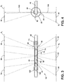
FIG. 3 is an elevation view of the foot end ofFIG. 2 ; and -
FIG. 4 is a side view of the foot end ofFIG. 2 . - For purposes of description herein, the terms "upper," "lower," "right," "left," "rear," "front," "vertical," "horizontal," and derivatives thereof shall relate to the disclosure as oriented in
FIG. 1 . Unless stated otherwise, the term "front" shall refer to a surface of the device closest to an intended viewer, and the term "rear" shall refer to a surface of the device furthest from the intended viewer. However, it is to be understood that the disclosure may assume various alternative orientations, except where expressly specified to the contrary. It is also to be understood that the specific devices and processes illustrated in the attached drawings, and described in the following specification are simply exemplary embodiments. Hence, specific dimensions and other physical characteristics relating to the embodiments disclosed herein are not to be considered as limiting. - The terms "including," "comprises," "comprising," or any other variation thereof, are intended to cover a non-exclusive inclusion, such that a process, method, article, or apparatus that comprises a list of elements does not include only those elements but may include other elements not expressly listed or inherent to such process, method, article, or apparatus. An element preceded by "comprises a .. . " does not, without more constraints, preclude the existence of additional identical elements in the process, method, article, or apparatus that comprises the element.
- Referring to
FIGS. 1-4 ,reference numeral 10 generally designates a patient support apparatus, which may be in the form of a stretcher. Thepatient support apparatus 10 may include ahead end 14 and afoot end 18. Thefoot end 18 may include asupport frame 22 and aprojection housing 26. Theprojection housing 26 is rotatably coupled to thesupport frame 22. Theprojection housing 26 includes a projector configured to project animage 30 from thesupport frame 22. An angle ofprojection 34 of theimage 30 is adjusted by rotation of theprojection housing 26. - Referring now to
FIG. 1 , thepatient support apparatus 10 may include a stretcher. While described as thepatient support apparatus 10, it is within the scope of the disclosure that thepatient support apparatus 10 may include a hospital bed, a bed frame, a mattress, or any suitable structure for supporting a patient, including, but not limited to: other types of beds, surgical tables, examination tables, and the like. - The illustrated
patient support apparatus 10 ofFIG. 1 includes aframe 38, which may be in the form of a base frame supported on casters orwheels 40. Thebase frame 38 is configured to support anupper frame 42. Theupper frame 42 may be operable between raised, lowered, and tilted positions relative to thebase frame 38. Thepatient support apparatus 10 may include a support member, such as amattress 46, disposed on theupper frame 42. - The
support frame 22 may be fixed relative to thepatient support apparatus 10. In some examples, thesupport frame 22 extends laterally along thefoot end 18 of thepatient support apparatus 10 and is integral with, or coupled with theupper frame 42. In some examples, thesupport frame 22 may be fixedly attached to theupper frame 42. Thesupport frame 22 may retain therotatable projection housing 26, which may be in the form of a drum. Theprojection housing 26 may include at least onelight projector 48 disposed inside theprojection housing 26 and configured to project at least one image, such as theimage 30. Theprojection housing 26 may include multiple light projectors. For example, inFIG. 1 , three light projectors are disposed in theprojection housing 26 and are configured to project afirst image 30, asecond image 50, and athird image 54. The images, 30, 50, and 54 may be in the form of a light presentation visible on a surface for indicating conditions or statuses of a function of thepatient support apparatus 10, which may include, but are not limited to: a level of charge of a battery, a status of an incontinence detection system, a current head angle, an alert condition, an operating condition of themattress 46, a bed exit alarm, an indication of whether or not thepatient support apparatus 10 is in its lowest position, an indication of whether or not side rails are in a raised position, etc. -
FIG. 2 illustrates an enlarged view of thefoot end 18 of thepatient support apparatus 10. Thesupport frame 22 may include anupper portion 58, amiddle portion 62 and alower portion 66. Thesupport frame 22 may be constructed such that at least a portion of theprojection housing 26 is visible at theupper portion 58 and thelower portion 66. In this way, theprojection housing 26 may not be completely concealed by thesupport frame 22. For example, thesupport frame 22 may define a first, or upper,aperture 70 and a second, or lower,aperture 72. Themiddle portion 62 may include at least oneindicator 74, which may include a light source, such as a light emitting diode (LED), configured to selectively illuminate and graphically display conditions or statuses of functions of thepatient support apparatus 10. In some examples, threeindicators images - The
projection housing 26 may be disposed within thesupport frame 22. Further, theprojection housing 26 includes abody 84 defining at least one aperture, which may includeapertures light projector 48 may include threelight projectors projection housing 26. Thelight projectors apertures body 84 and onto a surface, S (FIG. 3 ). Accordingly, thelight projectors apertures images projection housing 26 and thesupport frame 22. Theapertures light projectors images indicators -
Lenses apertures light projectors light projectors lenses lenses images FIG. 3 ) by concentrating or dispersing light rays from a light beam. Thelenses focus ring 110 may be operably coupled with thelenses lenses images focus ring 110. Adjusting the focal distance of theimages images focus ring 110 may be coupled with thesupport frame 22. However, it is within the scope of various aspects described herein for thefocus ring 110 to be coupled with any suitable component of thepatient support apparatus 10, which may include theupper frame 42. Alternatively, thelenses optical system 114, which may include one or more sensors, a controller, and a motor. In some examples, the autofocusoptical system 114 may be disposed inside theprojection housing 26. - The
projection housing 26 may include at least one light source adjacent eachlight projector images projection housing 26body 84 may define a first aperture and a second aperture and include a first light source configured to emit a first beam of light and a second light source configured to emit a second beam of light where first and second projectors direct the first and second beams of light through corresponding first and second apertures. In some examples, an amber LED and a green LED may be disposed on a circuit board adjacent eachlight projector 48. Additionally, a slide may be positioned adjacent eachlight projector 48, which may include a position aligned between theprojector aperture images light projector 48 and then through the slide and thelens 98 to present theimage 30 in green. Acontroller 118 of thepatient support apparatus 10 may be configured to selectively illuminate the light source(s). Furthermore, thecontroller 118 may signal the light source(s) to rapidly turn off and on. Thus, thelight projector 48 may selectively project theimage 30 in a flashing manner to generate a flashing projection. It is also within the scope of the disclosure to adjust the focus of theimages apertures focus ring 110 may be operably coupled with the LEDs and the circuit board. - The
projection housing 26 may be configured to spin, or rotate to adjust the position of theapertures knob 122 may be operably coupled with theprojection housing 26 for manual rotation of theprojection housing 26 relative to thesupport frame 22, as illustrated by arrow K. While illustrated as moving away from thepatient support apparatus 10, theknob 122 and/orprojection housing 26 may rotate towards thepatient support apparatus 10, or bi-directionally. Additionally, a release lock, which may be in the form of abutton 126, may be provided to selectively control rotation of theprojection housing 26. Thebutton 126 may be coupled with theknob 122 such that pushing thebutton 126 releases a locking mechanism and allows for rotation of theprojection housing 26. While illustrated as abutton 126, the release lock may be in the form of any suitable lock for securing and releasing theprojection housing 26 for rotation. In this way, theimages projection housing 26 may automatically rotate when commanded by thecontroller 118 of thepatient support apparatus 10. In some examples, anelectric motor 130 in communication with thecontroller 118 may be operably coupled to theprojection housing 26 to control theelectric motor 130 to automatically rotate theprojection housing 26. A user may provide input to thecontroller 118 for commanding the rotation of theprojection housing 26, which may include a position of theprojection housing 26. Input can be provided to thecontroller 118 via any suitable technique, such as touch input to a graphical user interface on a remote or local device. In some examples, rotation of theknob 122 may activate the light sources for projection of theimages projection housing 26 into position via thebutton 126 may activate the light sources. The light sources may be configured to remain activated until theprojection housing 26 is rotated into an off position. The off position may include theapertures middle portion 62 of thesupport frame 22 such that theapertures support frame 22. It is within the scope of the disclosure for thecontroller 118 to activate and deactivate the light sources in a variety of ways including, but not limited to: timing out after a predetermined amount of time, which may be a period of 24 hours or more, in response to audible commands, in response to input from a remote device, a capacitive touch input provided by user, in response to signals from a motion sensor, an ambient light sensor, a proximity sensor, and the like. In some examples, the light source(s) may remain activated as a default condition until the controller detects a deactivation signal. - Referring now to
FIG. 3 , an elevation view of thefoot end 18 is illustrated. The beams of light forming theimages projection housing 26 may be rotated such that theapertures upper portion 58 or thelower portion 66 of thesupport frame 22. Positioning theapertures upper portion 58, or aligning theprojectors upper aperture 70, may enable theimages apertures lower portion 66, or aligning theprojectors lower aperture 72, may enable theimages images projection housing 26 may include an additional set of apertures and/or light projectors for projecting theimages images images images images -
FIG. 4 is a side view of thefoot end 18 illustrating the angle ofprojection 34 of theimage 30. Afirst vector 140 may represent a 180° position and asecond vector 144 may represent a 0° position. Theprojection housing 26 may be rotatable from 0° to 360° in order to provide for multiple angles ofprojection 34 as the rotational position of theprojection housing 26 relative to thesupport frame 22 may determine where theimages projection housing 22 adjusts the angle at which theimage 30 is projected. In some examples, positioning theapertures projection housing 26 at approximately 180° may position theimage 30 onto the ceiling surface SC and positioning theapertures image 30 onto the floor surface SF. It may be desirable to position the image(s) 30, 50, 54 onto a positon other than the ceiling or the floor. For example, it may be desirable to position the image(s) 30, 50, 54 on a wall or dividing curtain surface, which may include positioning theapertures - Furthermore, in an example where the
middle portion 62 of thesupport frame 22 is positioned at approximately 90°, theimages foot end 18 by themiddle portion 62, which may be due to theprojection housing 26 being in the off position (i.e. theapertures support frame 22 to not include themiddle portion 62 such that the angles ofprojection 34 may include angles of approximately 90°. - For purposes of this disclosure, the term "coupled" (in all of its forms, couple, coupling, coupled, etc.) generally means the joining of two components (electrical or mechanical) directly or indirectly to one another. Such joining may be stationary in nature or movable in nature. Such joining may be achieved with the two components (electrical or mechanical) and any additional intermediate members being integrally formed as a single unitary body with one another or with the two components. Such joining may be permanent in nature or may be removable or releasable in nature unless otherwise stated.
- It is also important to note that the construction and arrangement of the elements of the disclosure, as shown in the exemplary embodiments, is illustrative only. Although only a few embodiments have been described in detail in this disclosure, those skilled in the art who review this disclosure will readily appreciate that many modifications are possible (e.g., variations in sizes, dimensions, structures, shapes and proportions of the various elements, values of parameters, mounting arrangements, use of materials, colors, orientations, etc.). For example, elements shown as integrally formed may be constructed of multiple parts, or elements shown as multiple parts may be integrally formed, the operation of the interfaces may be reversed or otherwise varied, the length or width of the structures and/or members or connector or other elements of the system may be varied, the nature or number of adjustment positions provided between the elements may be varied. It should be noted that the elements and/or assemblies of the system may be constructed from any of a wide variety of materials that provide sufficient strength or durability, in any of a wide variety of colors, textures, and combinations. Other substitutions, modifications, changes, and omissions may be made in the design, operating conditions, and arrangement of the desired and other exemplary embodiments.
- It will be understood that any described processes or steps within described processes may be combined with other disclosed processes or steps. The exemplary structures and processes disclosed herein are for illustrative purposes and are not to be construed as limiting.
- Embodiments of the invention can be described with reference to the following numbered clauses, with preferred features laid out in the dependent clauses:
- 1. A patient support apparatus comprising: a support frame; and a projection housing rotatably coupled with the support frame, the projection housing comprising: a body defining an aperture; a light source configured to emit a beam of light; and a projector configured to direct the beam of light through the aperture in the body and onto a surface.
- 2. The patient support apparatus of clause 1, wherein the beam of light generates an image indicating one of a condition and status of a function of the patient support apparatus.
- 3. The patient support apparatus of either clause 1 or clause 2, wherein rotation of the projection housing adjusts an angle at which an image is projected.
- 4. The patient support apparatus of any one of clauses 1 to 3, further comprising: a slide defining a graphic, wherein the slide is aligned between the projector and the aperture.
- 5. A patient support apparatus comprising: a head end and a foot end; a support frame coupled to one of the head and food end; and a projection housing disposed within and rotatably coupled to the support frame, the projection housing comprising: a body defining a first aperture and a second aperture; a first light source configured to emit a first beam of light; a second light source configured to emit a second beam of light; a first projector configured to direct the first beam of light through the first aperture in the body; a second projector configured to direct the second beam of light through the second aperture in the body, wherein upon alignment with the first and second apertures the first and second projectors are configured to project a first image and a second image, respectively, onto a surface.
- 6. The patient support apparatus of clause 5, wherein an angle of projection of the first and second images is adjusted by rotation of the projection housing relative to the support frame.
- 7. The patient support apparatus of either clause 5 or
clause 6, wherein the first and second images indicate one of a condition and status of a function of the patient support apparatus.
Claims (15)
- A patient support apparatus (10) comprising:a support frame (22); anda projection housing (26) rotatably coupled to the support frame (22), the projection housing (26) comprising:
a projector (48, 48a, 48b, 48c) configured to project an image (30, 50, 54) from the support frame (22), wherein an angle of projection (34) of the image (30, 50, 54) is adjusted by rotation of the projection housing (26). - The patient support apparatus (10) of claim 1, wherein the support frame (22) is fixed relative to the patient support apparatus (10).
- The patient support apparatus (10) of either of claims 1 or 2, wherein the support frame (22) comprises an indicator (74, 78, 82) configured to selectively illuminate.
- The patient support apparatus (10) of claim 3, wherein the indicator (74, 78, 82) corresponds to and is in lateral alignment with the projector (48, 48a, 48b, 48c).
- The patient support apparatus (10) of any of claims 1-4, further comprising:
a knob (122) operably coupled with the projection housing (26) for rotation of the projection housing (26) relative to the support frame (22). - The patient support apparatus (10) of any of claims 1-5, wherein the projection housing (26) further comprises a lens (98, 102, 106) configured to adjust the focus of the image (30, 50, 54) on a surface (S, SF, SC).
- The patient support apparatus (10) of claim 6, wherein the lens (98, 102, 106) is operably coupled with a focus ring (110) configured to shift the lens (98, 102, 106), thereby adjusting the clarity of the image (30, 50, 54) on the surface (S, SF, SC).
- The patient support apparatus (10) of claim 6, wherein the lens (98, 102, 106) is operably coupled with an autofocus optical system (114) configured to automatically shift the lens (98, 102, 106), thereby adjusting the focal distance of the image (30, 50, 54) on the surface (S, SF, SC).
- The patient support apparatus (10) of any preceding claim, wherein the projection housing (26) further comprises:a light source configured to provide a beam of light; anda slide defining a graphic, wherein the projector (48, 48a, 48b, 48c) is configured to project the beam of light through the slide to generate the image (30, 50, 54).
- The patient support apparatus (10) of any preceding claim, wherein the projector (48, 48a, 48b, 48c) is configured to selectively project the image (30, 50, 54) to generate a flashing projection.
- The patient support apparatus (10) of any preceding claim, further comprising:
a release lock (126) configured to selectively control rotation of the projection housing (26). - The patient support apparatus (10) of any preceding claim, wherein the support frame (22) further defines an upper aperture (70) and a lower aperture (72) and aligning the projector (48, 48a, 48b, 48c) adjacent the upper aperture (70) positions the image (30, 50, 54) adjacent a ceiling and aligning the projector (48, 48a, 48b, 48c) adjacent the lower aperture (72) positions the image (30, 50, 54) adjacent a floor.
- The patient support apparatus (10) of any preceding claim, further comprising:an electric motor (130) operably coupled to the projection housing (26);a controller (118) in communication with the electric motor (130) and configured to control the electric motor (130) to rotate the projection housing (26).
- The patient support apparatus (10) of any preceding claim, wherein the patient support apparatus (10) is a stretcher.
- The patient support apparatus (10) of any preceding claim, wherein a light source is configured to emit a beam of light and the beam of light generates the image (30, 50, 54).
Applications Claiming Priority (2)
| Application Number | Priority Date | Filing Date | Title |
|---|---|---|---|
| US201962866844P | 2019-06-26 | 2019-06-26 | |
| US16/907,645 US11592161B2 (en) | 2019-06-26 | 2020-06-22 | Positionable projections for a patient support apparatus |
Publications (2)
| Publication Number | Publication Date |
|---|---|
| EP3757675A1 true EP3757675A1 (en) | 2020-12-30 |
| EP3757675B1 EP3757675B1 (en) | 2024-01-10 |
Family
ID=71138601
Family Applications (1)
| Application Number | Title | Priority Date | Filing Date |
|---|---|---|---|
| EP20181765.7A Active EP3757675B1 (en) | 2019-06-26 | 2020-06-23 | Positionable projections for a patient support apparatus |
Country Status (3)
| Country | Link |
|---|---|
| US (1) | US11592161B2 (en) |
| EP (1) | EP3757675B1 (en) |
| CN (1) | CN214484633U (en) |
Families Citing this family (2)
| Publication number | Priority date | Publication date | Assignee | Title |
|---|---|---|---|---|
| US12672831B2 (en) * | 2021-11-16 | 2026-07-07 | John De Leo | Glucose reading projection device and method |
| KR20260034497A (en) * | 2024-09-04 | 2026-03-11 | 삼성전자주식회사 | Movable projector |
Citations (5)
| Publication number | Priority date | Publication date | Assignee | Title |
|---|---|---|---|---|
| JPS63149971A (en) * | 1986-12-15 | 1988-06-22 | Kawasaki Heavy Ind Ltd | Picture projector |
| US8607388B1 (en) * | 2012-07-10 | 2013-12-17 | Hill-Rom Services, Inc. | Patient-support apparatus having patient entertainment projector |
| EP2777670A1 (en) * | 2013-03-14 | 2014-09-17 | Hill-Rom Services, Inc. | Multi-alert lights for hospital bed |
| EP2918255A1 (en) * | 2014-03-11 | 2015-09-16 | Hill-Rom Services, Inc. | Caregiver universal remote cart for patient bed control |
| US20180184984A1 (en) * | 2017-01-04 | 2018-07-05 | Hill-Rom Services, Inc. | Patient support apparatus having vital signs monitoring and alerting |
Family Cites Families (4)
| Publication number | Priority date | Publication date | Assignee | Title |
|---|---|---|---|---|
| US20140204347A1 (en) * | 2013-01-22 | 2014-07-24 | Qunomic Virtual Technology, LLC | Message Projection System |
| KR101870183B1 (en) * | 2016-06-07 | 2018-06-22 | 안성호 | Bed System having Function of Image Output |
| US20180084921A1 (en) * | 2016-09-29 | 2018-03-29 | Apex Health Care Mfg, Inc. | Projector Fixed on Electric Bed |
| KR101940397B1 (en) * | 2017-03-15 | 2019-01-18 | 안성호 | Bed System with Beam Projector |
-
2020
- 2020-06-22 US US16/907,645 patent/US11592161B2/en active Active
- 2020-06-23 EP EP20181765.7A patent/EP3757675B1/en active Active
- 2020-06-28 CN CN202021221897.8U patent/CN214484633U/en active Active
Patent Citations (5)
| Publication number | Priority date | Publication date | Assignee | Title |
|---|---|---|---|---|
| JPS63149971A (en) * | 1986-12-15 | 1988-06-22 | Kawasaki Heavy Ind Ltd | Picture projector |
| US8607388B1 (en) * | 2012-07-10 | 2013-12-17 | Hill-Rom Services, Inc. | Patient-support apparatus having patient entertainment projector |
| EP2777670A1 (en) * | 2013-03-14 | 2014-09-17 | Hill-Rom Services, Inc. | Multi-alert lights for hospital bed |
| EP2918255A1 (en) * | 2014-03-11 | 2015-09-16 | Hill-Rom Services, Inc. | Caregiver universal remote cart for patient bed control |
| US20180184984A1 (en) * | 2017-01-04 | 2018-07-05 | Hill-Rom Services, Inc. | Patient support apparatus having vital signs monitoring and alerting |
Also Published As
| Publication number | Publication date |
|---|---|
| US20200408386A1 (en) | 2020-12-31 |
| CN214484633U (en) | 2021-10-26 |
| EP3757675B1 (en) | 2024-01-10 |
| US11592161B2 (en) | 2023-02-28 |
Similar Documents
| Publication | Publication Date | Title |
|---|---|---|
| US11653826B2 (en) | Medical observation system, control method, and program in which illumination light is controlled in accordance with a usage state of an image sensor | |
| EP3757675B1 (en) | Positionable projections for a patient support apparatus | |
| US10485507B2 (en) | Medical X-ray photographing apparatus | |
| JP4462377B2 (en) | Multifunctional ophthalmic examination device | |
| CN102067732B (en) | Stage-lighting apparatus and method for controlling the orientation of a light beam emitted by said apparatus | |
| KR20130057991A (en) | Tube alignment for mobile radiography system | |
| CN102949196B (en) | The operation device of lonizing radiation generator and radiography systems | |
| US10345689B2 (en) | Lighting device | |
| CN204600425U (en) | Ophthalmologic apparatus | |
| US20180243151A1 (en) | Robotic operating table and robotic operating table operation apparatus | |
| ES2954287T3 (en) | Electronic patient bed ruler | |
| US11439477B2 (en) | Medical observation system | |
| WO2015038595A1 (en) | Kinematic light control system | |
| WO2010064492A1 (en) | Multifunction ophthalmic examination apparatus | |
| KR101766821B1 (en) | rotation angle automatic control system of display and the control method | |
| JP6845983B2 (en) | Slit lamp | |
| JP6662149B2 (en) | Ophthalmic equipment | |
| US20210358616A1 (en) | Device, system and method for monitoring a subject | |
| CN115590704A (en) | Operating table system, operating table and remote controller | |
| US11994272B2 (en) | Lighting assembly and illumination system having a lighting assembly | |
| JPH05277071A (en) | Optometric apparatus | |
| JP6764188B2 (en) | X-ray diagnostic equipment | |
| JP4513721B2 (en) | Light control device | |
| JPH06314507A (en) | Remote control lighting device with irradiation point detector | |
| JP2000316813A (en) | Fundus camera |
Legal Events
| Date | Code | Title | Description |
|---|---|---|---|
| PUAI | Public reference made under article 153(3) epc to a published international application that has entered the european phase |
Free format text: ORIGINAL CODE: 0009012 |
|
| STAA | Information on the status of an ep patent application or granted ep patent |
Free format text: STATUS: THE APPLICATION HAS BEEN PUBLISHED |
|
| AK | Designated contracting states |
Kind code of ref document: A1 Designated state(s): AL AT BE BG CH CY CZ DE DK EE ES FI FR GB GR HR HU IE IS IT LI LT LU LV MC MK MT NL NO PL PT RO RS SE SI SK SM TR |
|
| AX | Request for extension of the european patent |
Extension state: BA ME |
|
| STAA | Information on the status of an ep patent application or granted ep patent |
Free format text: STATUS: REQUEST FOR EXAMINATION WAS MADE |
|
| 17P | Request for examination filed |
Effective date: 20210630 |
|
| RBV | Designated contracting states (corrected) |
Designated state(s): AL AT BE BG CH CY CZ DE DK EE ES FI FR GB GR HR HU IE IS IT LI LT LU LV MC MK MT NL NO PL PT RO RS SE SI SK SM TR |
|
| GRAP | Despatch of communication of intention to grant a patent |
Free format text: ORIGINAL CODE: EPIDOSNIGR1 |
|
| STAA | Information on the status of an ep patent application or granted ep patent |
Free format text: STATUS: GRANT OF PATENT IS INTENDED |
|
| INTG | Intention to grant announced |
Effective date: 20230523 |
|
| GRAS | Grant fee paid |
Free format text: ORIGINAL CODE: EPIDOSNIGR3 |
|
| GRAA | (expected) grant |
Free format text: ORIGINAL CODE: 0009210 |
|
| STAA | Information on the status of an ep patent application or granted ep patent |
Free format text: STATUS: THE PATENT HAS BEEN GRANTED |
|
| AK | Designated contracting states |
Kind code of ref document: B1 Designated state(s): AL AT BE BG CH CY CZ DE DK EE ES FI FR GB GR HR HU IE IS IT LI LT LU LV MC MK MT NL NO PL PT RO RS SE SI SK SM TR |
|
| REG | Reference to a national code |
Ref country code: GB Ref legal event code: FG4D |
|
| REG | Reference to a national code |
Ref country code: CH Ref legal event code: EP |
|
| REG | Reference to a national code |
Ref country code: DE Ref legal event code: R096 Ref document number: 602020024105 Country of ref document: DE |
|
| REG | Reference to a national code |
Ref country code: IE Ref legal event code: FG4D |
|
| REG | Reference to a national code |
Ref country code: LT Ref legal event code: MG9D |
|
| REG | Reference to a national code |
Ref country code: NL Ref legal event code: MP Effective date: 20240110 |
|
| REG | Reference to a national code |
Ref country code: AT Ref legal event code: MK05 Ref document number: 1649371 Country of ref document: AT Kind code of ref document: T Effective date: 20240110 |
|
| PG25 | Lapsed in a contracting state [announced via postgrant information from national office to epo] |
Ref country code: NL Free format text: LAPSE BECAUSE OF FAILURE TO SUBMIT A TRANSLATION OF THE DESCRIPTION OR TO PAY THE FEE WITHIN THE PRESCRIBED TIME-LIMIT Effective date: 20240110 |
|
| PG25 | Lapsed in a contracting state [announced via postgrant information from national office to epo] |
Ref country code: NL Free format text: LAPSE BECAUSE OF FAILURE TO SUBMIT A TRANSLATION OF THE DESCRIPTION OR TO PAY THE FEE WITHIN THE PRESCRIBED TIME-LIMIT Effective date: 20240110 |
|
| PG25 | Lapsed in a contracting state [announced via postgrant information from national office to epo] |
Ref country code: IS Free format text: LAPSE BECAUSE OF FAILURE TO SUBMIT A TRANSLATION OF THE DESCRIPTION OR TO PAY THE FEE WITHIN THE PRESCRIBED TIME-LIMIT Effective date: 20240510 |
|
| PG25 | Lapsed in a contracting state [announced via postgrant information from national office to epo] |
Ref country code: LT Free format text: LAPSE BECAUSE OF FAILURE TO SUBMIT A TRANSLATION OF THE DESCRIPTION OR TO PAY THE FEE WITHIN THE PRESCRIBED TIME-LIMIT Effective date: 20240110 |
|
| PG25 | Lapsed in a contracting state [announced via postgrant information from national office to epo] |
Ref country code: GR Free format text: LAPSE BECAUSE OF FAILURE TO SUBMIT A TRANSLATION OF THE DESCRIPTION OR TO PAY THE FEE WITHIN THE PRESCRIBED TIME-LIMIT Effective date: 20240411 |
|
| PG25 | Lapsed in a contracting state [announced via postgrant information from national office to epo] |
Ref country code: HR Free format text: LAPSE BECAUSE OF FAILURE TO SUBMIT A TRANSLATION OF THE DESCRIPTION OR TO PAY THE FEE WITHIN THE PRESCRIBED TIME-LIMIT Effective date: 20240110 Ref country code: RS Free format text: LAPSE BECAUSE OF FAILURE TO SUBMIT A TRANSLATION OF THE DESCRIPTION OR TO PAY THE FEE WITHIN THE PRESCRIBED TIME-LIMIT Effective date: 20240410 |
|
| PG25 | Lapsed in a contracting state [announced via postgrant information from national office to epo] |
Ref country code: ES Free format text: LAPSE BECAUSE OF FAILURE TO SUBMIT A TRANSLATION OF THE DESCRIPTION OR TO PAY THE FEE WITHIN THE PRESCRIBED TIME-LIMIT Effective date: 20240110 |
|
| PG25 | Lapsed in a contracting state [announced via postgrant information from national office to epo] |
Ref country code: AT Free format text: LAPSE BECAUSE OF FAILURE TO SUBMIT A TRANSLATION OF THE DESCRIPTION OR TO PAY THE FEE WITHIN THE PRESCRIBED TIME-LIMIT Effective date: 20240110 |
|
| PG25 | Lapsed in a contracting state [announced via postgrant information from national office to epo] |
Ref country code: RS Free format text: LAPSE BECAUSE OF FAILURE TO SUBMIT A TRANSLATION OF THE DESCRIPTION OR TO PAY THE FEE WITHIN THE PRESCRIBED TIME-LIMIT Effective date: 20240410 Ref country code: NO Free format text: LAPSE BECAUSE OF FAILURE TO SUBMIT A TRANSLATION OF THE DESCRIPTION OR TO PAY THE FEE WITHIN THE PRESCRIBED TIME-LIMIT Effective date: 20240410 Ref country code: LT Free format text: LAPSE BECAUSE OF FAILURE TO SUBMIT A TRANSLATION OF THE DESCRIPTION OR TO PAY THE FEE WITHIN THE PRESCRIBED TIME-LIMIT Effective date: 20240110 Ref country code: IS Free format text: LAPSE BECAUSE OF FAILURE TO SUBMIT A TRANSLATION OF THE DESCRIPTION OR TO PAY THE FEE WITHIN THE PRESCRIBED TIME-LIMIT Effective date: 20240510 Ref country code: HR Free format text: LAPSE BECAUSE OF FAILURE TO SUBMIT A TRANSLATION OF THE DESCRIPTION OR TO PAY THE FEE WITHIN THE PRESCRIBED TIME-LIMIT Effective date: 20240110 Ref country code: GR Free format text: LAPSE BECAUSE OF FAILURE TO SUBMIT A TRANSLATION OF THE DESCRIPTION OR TO PAY THE FEE WITHIN THE PRESCRIBED TIME-LIMIT Effective date: 20240411 Ref country code: ES Free format text: LAPSE BECAUSE OF FAILURE TO SUBMIT A TRANSLATION OF THE DESCRIPTION OR TO PAY THE FEE WITHIN THE PRESCRIBED TIME-LIMIT Effective date: 20240110 Ref country code: BG Free format text: LAPSE BECAUSE OF FAILURE TO SUBMIT A TRANSLATION OF THE DESCRIPTION OR TO PAY THE FEE WITHIN THE PRESCRIBED TIME-LIMIT Effective date: 20240110 Ref country code: AT Free format text: LAPSE BECAUSE OF FAILURE TO SUBMIT A TRANSLATION OF THE DESCRIPTION OR TO PAY THE FEE WITHIN THE PRESCRIBED TIME-LIMIT Effective date: 20240110 |
|
| PG25 | Lapsed in a contracting state [announced via postgrant information from national office to epo] |
Ref country code: PT Free format text: LAPSE BECAUSE OF FAILURE TO SUBMIT A TRANSLATION OF THE DESCRIPTION OR TO PAY THE FEE WITHIN THE PRESCRIBED TIME-LIMIT Effective date: 20240510 Ref country code: PL Free format text: LAPSE BECAUSE OF FAILURE TO SUBMIT A TRANSLATION OF THE DESCRIPTION OR TO PAY THE FEE WITHIN THE PRESCRIBED TIME-LIMIT Effective date: 20240110 |
|
| PG25 | Lapsed in a contracting state [announced via postgrant information from national office to epo] |
Ref country code: SE Free format text: LAPSE BECAUSE OF FAILURE TO SUBMIT A TRANSLATION OF THE DESCRIPTION OR TO PAY THE FEE WITHIN THE PRESCRIBED TIME-LIMIT Effective date: 20240110 Ref country code: PT Free format text: LAPSE BECAUSE OF FAILURE TO SUBMIT A TRANSLATION OF THE DESCRIPTION OR TO PAY THE FEE WITHIN THE PRESCRIBED TIME-LIMIT Effective date: 20240510 Ref country code: PL Free format text: LAPSE BECAUSE OF FAILURE TO SUBMIT A TRANSLATION OF THE DESCRIPTION OR TO PAY THE FEE WITHIN THE PRESCRIBED TIME-LIMIT Effective date: 20240110 Ref country code: LV Free format text: LAPSE BECAUSE OF FAILURE TO SUBMIT A TRANSLATION OF THE DESCRIPTION OR TO PAY THE FEE WITHIN THE PRESCRIBED TIME-LIMIT Effective date: 20240110 |
|
| PG25 | Lapsed in a contracting state [announced via postgrant information from national office to epo] |
Ref country code: DK Free format text: LAPSE BECAUSE OF FAILURE TO SUBMIT A TRANSLATION OF THE DESCRIPTION OR TO PAY THE FEE WITHIN THE PRESCRIBED TIME-LIMIT Effective date: 20240110 |
|
| REG | Reference to a national code |
Ref country code: DE Ref legal event code: R097 Ref document number: 602020024105 Country of ref document: DE |
|
| PG25 | Lapsed in a contracting state [announced via postgrant information from national office to epo] |
Ref country code: SM Free format text: LAPSE BECAUSE OF FAILURE TO SUBMIT A TRANSLATION OF THE DESCRIPTION OR TO PAY THE FEE WITHIN THE PRESCRIBED TIME-LIMIT Effective date: 20240110 |
|
| PG25 | Lapsed in a contracting state [announced via postgrant information from national office to epo] |
Ref country code: EE Free format text: LAPSE BECAUSE OF FAILURE TO SUBMIT A TRANSLATION OF THE DESCRIPTION OR TO PAY THE FEE WITHIN THE PRESCRIBED TIME-LIMIT Effective date: 20240110 Ref country code: CZ Free format text: LAPSE BECAUSE OF FAILURE TO SUBMIT A TRANSLATION OF THE DESCRIPTION OR TO PAY THE FEE WITHIN THE PRESCRIBED TIME-LIMIT Effective date: 20240110 |
|
| PG25 | Lapsed in a contracting state [announced via postgrant information from national office to epo] |
Ref country code: SK Free format text: LAPSE BECAUSE OF FAILURE TO SUBMIT A TRANSLATION OF THE DESCRIPTION OR TO PAY THE FEE WITHIN THE PRESCRIBED TIME-LIMIT Effective date: 20240110 |
|
| PG25 | Lapsed in a contracting state [announced via postgrant information from national office to epo] |
Ref country code: SM Free format text: LAPSE BECAUSE OF FAILURE TO SUBMIT A TRANSLATION OF THE DESCRIPTION OR TO PAY THE FEE WITHIN THE PRESCRIBED TIME-LIMIT Effective date: 20240110 Ref country code: SK Free format text: LAPSE BECAUSE OF FAILURE TO SUBMIT A TRANSLATION OF THE DESCRIPTION OR TO PAY THE FEE WITHIN THE PRESCRIBED TIME-LIMIT Effective date: 20240110 Ref country code: RO Free format text: LAPSE BECAUSE OF FAILURE TO SUBMIT A TRANSLATION OF THE DESCRIPTION OR TO PAY THE FEE WITHIN THE PRESCRIBED TIME-LIMIT Effective date: 20240110 Ref country code: EE Free format text: LAPSE BECAUSE OF FAILURE TO SUBMIT A TRANSLATION OF THE DESCRIPTION OR TO PAY THE FEE WITHIN THE PRESCRIBED TIME-LIMIT Effective date: 20240110 Ref country code: DK Free format text: LAPSE BECAUSE OF FAILURE TO SUBMIT A TRANSLATION OF THE DESCRIPTION OR TO PAY THE FEE WITHIN THE PRESCRIBED TIME-LIMIT Effective date: 20240110 Ref country code: CZ Free format text: LAPSE BECAUSE OF FAILURE TO SUBMIT A TRANSLATION OF THE DESCRIPTION OR TO PAY THE FEE WITHIN THE PRESCRIBED TIME-LIMIT Effective date: 20240110 |
|
| PLBE | No opposition filed within time limit |
Free format text: ORIGINAL CODE: 0009261 |
|
| STAA | Information on the status of an ep patent application or granted ep patent |
Free format text: STATUS: NO OPPOSITION FILED WITHIN TIME LIMIT |
|
| PG25 | Lapsed in a contracting state [announced via postgrant information from national office to epo] |
Ref country code: IT Free format text: LAPSE BECAUSE OF FAILURE TO SUBMIT A TRANSLATION OF THE DESCRIPTION OR TO PAY THE FEE WITHIN THE PRESCRIBED TIME-LIMIT Effective date: 20240110 |
|
| 26N | No opposition filed |
Effective date: 20241011 |
|
| PG25 | Lapsed in a contracting state [announced via postgrant information from national office to epo] |
Ref country code: IT Free format text: LAPSE BECAUSE OF FAILURE TO SUBMIT A TRANSLATION OF THE DESCRIPTION OR TO PAY THE FEE WITHIN THE PRESCRIBED TIME-LIMIT Effective date: 20240110 |
|
| PG25 | Lapsed in a contracting state [announced via postgrant information from national office to epo] |
Ref country code: MC Free format text: LAPSE BECAUSE OF FAILURE TO SUBMIT A TRANSLATION OF THE DESCRIPTION OR TO PAY THE FEE WITHIN THE PRESCRIBED TIME-LIMIT Effective date: 20240110 |
|
| REG | Reference to a national code |
Ref country code: CH Ref legal event code: PL |
|
| PG25 | Lapsed in a contracting state [announced via postgrant information from national office to epo] |
Ref country code: LU Free format text: LAPSE BECAUSE OF NON-PAYMENT OF DUE FEES Effective date: 20240623 |
|
| PG25 | Lapsed in a contracting state [announced via postgrant information from national office to epo] |
Ref country code: IE Free format text: LAPSE BECAUSE OF NON-PAYMENT OF DUE FEES Effective date: 20240623 |
|
| PG25 | Lapsed in a contracting state [announced via postgrant information from national office to epo] |
Ref country code: SI Free format text: LAPSE BECAUSE OF FAILURE TO SUBMIT A TRANSLATION OF THE DESCRIPTION OR TO PAY THE FEE WITHIN THE PRESCRIBED TIME-LIMIT Effective date: 20240110 Ref country code: CH Free format text: LAPSE BECAUSE OF NON-PAYMENT OF DUE FEES Effective date: 20240630 Ref country code: BE Free format text: LAPSE BECAUSE OF NON-PAYMENT OF DUE FEES Effective date: 20240630 |
|
| REG | Reference to a national code |
Ref country code: BE Ref legal event code: MM Effective date: 20240630 |
|
| PG25 | Lapsed in a contracting state [announced via postgrant information from national office to epo] |
Ref country code: FI Free format text: LAPSE BECAUSE OF FAILURE TO SUBMIT A TRANSLATION OF THE DESCRIPTION OR TO PAY THE FEE WITHIN THE PRESCRIBED TIME-LIMIT Effective date: 20240110 |
|
| PG25 | Lapsed in a contracting state [announced via postgrant information from national office to epo] |
Ref country code: CY Free format text: LAPSE BECAUSE OF FAILURE TO SUBMIT A TRANSLATION OF THE DESCRIPTION OR TO PAY THE FEE WITHIN THE PRESCRIBED TIME-LIMIT; INVALID AB INITIO Effective date: 20200623 |
|
| PG25 | Lapsed in a contracting state [announced via postgrant information from national office to epo] |
Ref country code: HU Free format text: LAPSE BECAUSE OF FAILURE TO SUBMIT A TRANSLATION OF THE DESCRIPTION OR TO PAY THE FEE WITHIN THE PRESCRIBED TIME-LIMIT; INVALID AB INITIO Effective date: 20200623 |
|
| PG25 | Lapsed in a contracting state [announced via postgrant information from national office to epo] |
Ref country code: TR Free format text: LAPSE BECAUSE OF FAILURE TO SUBMIT A TRANSLATION OF THE DESCRIPTION OR TO PAY THE FEE WITHIN THE PRESCRIBED TIME-LIMIT Effective date: 20240110 |
|
| PGFP | Annual fee paid to national office [announced via postgrant information from national office to epo] |
Ref country code: GB Payment date: 20260520 Year of fee payment: 7 |
|
| PGFP | Annual fee paid to national office [announced via postgrant information from national office to epo] |
Ref country code: DE Payment date: 20260520 Year of fee payment: 7 |
|
| PGFP | Annual fee paid to national office [announced via postgrant information from national office to epo] |
Ref country code: FR Payment date: 20260521 Year of fee payment: 7 |