EP3757654A2 - Optical deflector and optical scanning apparatus - Google Patents
Optical deflector and optical scanning apparatus Download PDFInfo
- Publication number
- EP3757654A2 EP3757654A2 EP20176867.8A EP20176867A EP3757654A2 EP 3757654 A2 EP3757654 A2 EP 3757654A2 EP 20176867 A EP20176867 A EP 20176867A EP 3757654 A2 EP3757654 A2 EP 3757654A2
- Authority
- EP
- European Patent Office
- Prior art keywords
- groove
- reflection surface
- mirror part
- rotation axis
- optical
- Prior art date
- Legal status (The legal status is an assumption and is not a legal conclusion. Google has not performed a legal analysis and makes no representation as to the accuracy of the status listed.)
- Granted
Links
Images







Classifications
-
- G—PHYSICS
- G02—OPTICS
- G02B—OPTICAL ELEMENTS, SYSTEMS OR APPARATUS
- G02B26/00—Optical devices or arrangements for the control of light using movable or deformable optical elements
- G02B26/08—Optical devices or arrangements for the control of light using movable or deformable optical elements for controlling the direction of light
- G02B26/10—Scanning systems
- G02B26/12—Scanning systems using multifaceted mirrors
- G02B26/125—Details of the optical system between the polygonal mirror and the image plane
-
- G—PHYSICS
- G02—OPTICS
- G02B—OPTICAL ELEMENTS, SYSTEMS OR APPARATUS
- G02B26/00—Optical devices or arrangements for the control of light using movable or deformable optical elements
- G02B26/08—Optical devices or arrangements for the control of light using movable or deformable optical elements for controlling the direction of light
- G02B26/0816—Optical devices or arrangements for the control of light using movable or deformable optical elements for controlling the direction of light by means of one or more reflecting elements
- G02B26/0833—Optical devices or arrangements for the control of light using movable or deformable optical elements for controlling the direction of light by means of one or more reflecting elements the reflecting element being a micromechanical device, e.g. a MEMS mirror, DMD
-
- G—PHYSICS
- G02—OPTICS
- G02B—OPTICAL ELEMENTS, SYSTEMS OR APPARATUS
- G02B26/00—Optical devices or arrangements for the control of light using movable or deformable optical elements
- G02B26/08—Optical devices or arrangements for the control of light using movable or deformable optical elements for controlling the direction of light
- G02B26/0816—Optical devices or arrangements for the control of light using movable or deformable optical elements for controlling the direction of light by means of one or more reflecting elements
- G02B26/0833—Optical devices or arrangements for the control of light using movable or deformable optical elements for controlling the direction of light by means of one or more reflecting elements the reflecting element being a micromechanical device, e.g. a MEMS mirror, DMD
- G02B26/0858—Optical devices or arrangements for the control of light using movable or deformable optical elements for controlling the direction of light by means of one or more reflecting elements the reflecting element being a micromechanical device, e.g. a MEMS mirror, DMD the reflecting means being moved or deformed by piezoelectric means
-
- G—PHYSICS
- G02—OPTICS
- G02B—OPTICAL ELEMENTS, SYSTEMS OR APPARATUS
- G02B26/00—Optical devices or arrangements for the control of light using movable or deformable optical elements
- G02B26/08—Optical devices or arrangements for the control of light using movable or deformable optical elements for controlling the direction of light
- G02B26/0816—Optical devices or arrangements for the control of light using movable or deformable optical elements for controlling the direction of light by means of one or more reflecting elements
- G02B26/0833—Optical devices or arrangements for the control of light using movable or deformable optical elements for controlling the direction of light by means of one or more reflecting elements the reflecting element being a micromechanical device, e.g. a MEMS mirror, DMD
- G02B26/0841—Optical devices or arrangements for the control of light using movable or deformable optical elements for controlling the direction of light by means of one or more reflecting elements the reflecting element being a micromechanical device, e.g. a MEMS mirror, DMD the reflecting element being moved or deformed by electrostatic means
-
- G—PHYSICS
- G02—OPTICS
- G02B—OPTICAL ELEMENTS, SYSTEMS OR APPARATUS
- G02B26/00—Optical devices or arrangements for the control of light using movable or deformable optical elements
- G02B26/08—Optical devices or arrangements for the control of light using movable or deformable optical elements for controlling the direction of light
- G02B26/0816—Optical devices or arrangements for the control of light using movable or deformable optical elements for controlling the direction of light by means of one or more reflecting elements
- G02B26/0833—Optical devices or arrangements for the control of light using movable or deformable optical elements for controlling the direction of light by means of one or more reflecting elements the reflecting element being a micromechanical device, e.g. a MEMS mirror, DMD
- G02B26/085—Optical devices or arrangements for the control of light using movable or deformable optical elements for controlling the direction of light by means of one or more reflecting elements the reflecting element being a micromechanical device, e.g. a MEMS mirror, DMD the reflecting means being moved or deformed by electromagnetic means
-
- G—PHYSICS
- G02—OPTICS
- G02B—OPTICAL ELEMENTS, SYSTEMS OR APPARATUS
- G02B26/00—Optical devices or arrangements for the control of light using movable or deformable optical elements
- G02B26/08—Optical devices or arrangements for the control of light using movable or deformable optical elements for controlling the direction of light
- G02B26/10—Scanning systems
- G02B26/101—Scanning systems with both horizontal and vertical deflecting means, e.g. raster or XY scanners
-
- G—PHYSICS
- G09—EDUCATION; CRYPTOGRAPHY; DISPLAY; ADVERTISING; SEALS
- G09G—ARRANGEMENTS OR CIRCUITS FOR CONTROL OF INDICATING DEVICES USING STATIC MEANS TO PRESENT VARIABLE INFORMATION
- G09G3/00—Control arrangements or circuits, of interest only in connection with visual indicators other than cathode-ray tubes
- G09G3/20—Control arrangements or circuits, of interest only in connection with visual indicators other than cathode-ray tubes for presentation of an assembly of a number of characters, e.g. a page, by composing the assembly by combination of individual elements arranged in a matrix no fixed position being assigned to or needed to be assigned to the individual characters or partial characters
- G09G3/2092—Details of a display terminals using a flat panel, the details relating to the control arrangement of the display terminal and to the interfaces thereto
-
- G—PHYSICS
- G09—EDUCATION; CRYPTOGRAPHY; DISPLAY; ADVERTISING; SEALS
- G09G—ARRANGEMENTS OR CIRCUITS FOR CONTROL OF INDICATING DEVICES USING STATIC MEANS TO PRESENT VARIABLE INFORMATION
- G09G3/00—Control arrangements or circuits, of interest only in connection with visual indicators other than cathode-ray tubes
- G09G3/20—Control arrangements or circuits, of interest only in connection with visual indicators other than cathode-ray tubes for presentation of an assembly of a number of characters, e.g. a page, by composing the assembly by combination of individual elements arranged in a matrix no fixed position being assigned to or needed to be assigned to the individual characters or partial characters
- G09G3/34—Control arrangements or circuits, of interest only in connection with visual indicators other than cathode-ray tubes for presentation of an assembly of a number of characters, e.g. a page, by composing the assembly by combination of individual elements arranged in a matrix no fixed position being assigned to or needed to be assigned to the individual characters or partial characters by control of light from an independent source
- G09G3/3433—Control arrangements or circuits, of interest only in connection with visual indicators other than cathode-ray tubes for presentation of an assembly of a number of characters, e.g. a page, by composing the assembly by combination of individual elements arranged in a matrix no fixed position being assigned to or needed to be assigned to the individual characters or partial characters by control of light from an independent source using light modulating elements actuated by an electric field and being other than liquid crystal devices and electrochromic devices
- G09G3/346—Control arrangements or circuits, of interest only in connection with visual indicators other than cathode-ray tubes for presentation of an assembly of a number of characters, e.g. a page, by composing the assembly by combination of individual elements arranged in a matrix no fixed position being assigned to or needed to be assigned to the individual characters or partial characters by control of light from an independent source using light modulating elements actuated by an electric field and being other than liquid crystal devices and electrochromic devices based on modulation of the reflection angle, e.g. micromirrors
Definitions
- the present invention relates to an optical deflector and an optical scanning apparatus.
- the optical deflector for MEMS comprises a mirror part that is reciprocally turned about a rotation axis, and reflects a light from an optical source in a direction depending on the deflection angle of the mirror part, to emit the reflected light as a scanning light.
- the scanning range and scanning position of the scanning light change depending on the deflection angle of the mirror part. Accordingly, it is necessary to detect the deflection angle of the mirror part for properly controlling the scanning light in the scanning range.
- An optical scanning apparatus in JP P2006-243225A comprises an optical sensor in an emission direction of the reflected light when the mirror part reaches an end portion of a deflection range. Thereby, the reflected light is detected by the optical sensor when the mirror part has a predetermined deflection angle at the end portion of the deflection range.
- a reflection surface of the mirror part is formed by a diffraction grating.
- a zero-order diffraction light emitted from the mirror part is used as the scanning light for the original use purpose.
- a first-order diffraction light enters a light receiving element, and is used for the detection of the deflection angle.
- the optical scanning apparatus in JP P2006-243225A can detect the deflection angle of the mirror part, only when the reflected light reaches the end portion of the deflection width.
- the optical scanning apparatus in JP P2011-118178A can detect various arbitrary deflection angles of the mirror part from the intensity of the first-order diffraction light.
- the direction of the emission of the first-order diffraction light from the optical deflector changes depending on the deflection angle of the mirror part. Accordingly, for detecting each deflection angle in the deflection width of the mirror part, the optical sensor needs to have a length corresponding to the deflection width of the first-order diffraction light, leading to increase in length.
- An object of the present invention is to provide an optical deflector and an optical scanning apparatus that can detect an arbitrary deflection angle of the mirror part while avoiding the increase in the length of the optical sensor for the detection of the deflection angle.
- An optical deflector of the present invention comprises:
- the optical deflector comprises the grooved reflection surface on the mirror part, and emits a two-time reflected light from the grooved reflection surface.
- the emission direction of the two-time reflected light about the first rotation axis is fixed regardless of the deflection angle of the mirror part about the first rotation axis. Further, two-time reflected lights from the longitudinal grooves of the grooved reflection surface interfere with each other, and therefore the intensity of the two-time reflected light changes depending on the deflection angle of the mirror part.
- both facing inclination surfaces of the V-groove may have inclination angles that are equal to each other with respect to a reference bottom plane, the reference bottom plane passing through a trough line of the V-groove and being parallel to the flat reflection surface.
- the facing inclination surfaces of the longitudinal groove may have a shape in which a bottom portion of the V-groove is cut off.
- the facing inclination surfaces of the longitudinal groove form the shape in which a bottom portion of the V-groove is cut off.
- the sum of the inclination angles of both facing inclination surfaces of the V-groove with respect to the reference bottom surface may be in a range of 80° to 120°.
- the mirror part may have the flat reflection surface and the grooved reflection surface on a surface of a common substrate layer formed of a crystal layer of silicon, and
- Miller indices of a principal surface of the crystal layer and the facing inclination surface of the longitudinal groove may be one and the other of (100) and (111) respectively.
- the inclination angle of each facing inclination surface with respect to the reference bottom plane may be 54.7°.
- the grooved reflection surface may be provided on the first rotation axis, and the first actuator may be a piezoelectric actuator, an electrostatic actuator or an electromagnetic actuator.
- the grooved reflection surface may be provided at a central portion of the mirror part.
- An optical scanning apparatus of the present invention comprises:
- the optical scanning apparatus of the present invention it is possible to detect an arbitrary deflection angle of the mirror part while avoiding the increase in the length of the optical sensor for the detection of the deflection angle.
- the optical sensor may be provided on both sides of a perpendicular reference plane that passes through a center of the mirror part perpendicularly to the flat reflection surface when the mirror part has a central deflection angle in a deflection width about the first rotation axis.
- the optical deflector may comprise a second actuator that reciprocally turns the mirror part about a second rotation axis orthogonal to the first rotation axis, and the optical sensor may extend along a scanning trajectory of scanning of the two-time reflected light from the mirror part when the mirror part is reciprocally turned about the second rotation axis.
- Another optical deflector of the present invention comprises:
- the present invention in a two-axis scanning type optical deflector, it is possible to detect an arbitrary deflection angle of the mirror part about the second rotation axis, using the two-time reflected light from the grooved reflection surface.
- both facing inclination surfaces of the V-groove may have inclination angles that are equal to each other with respect to a reference bottom plane, the reference bottom plane passing through a trough line of the V-groove and being parallel to the flat reflection surface, the facing inclination surface of the longitudinal groove may have a shape in which a bottom portion of the V-groove is cut off, a cut plane that passes through the V-groove parallel to the flat reflection surface at an intermediate position in a depth direction of the V-groove may be defined, the facing inclination surface of the V-groove may be divided along the cut plane into an opening-side portion and a closing-side portion, the opening-side portion being a portion on an opening side of the V-groove, the closing-side portion being a portion on a closing side of the V-groove, lengths of the opening-side portion and the closing-side portion on a transverse section of the V-groove may be Da
- An another optical scanning apparatus of the present invention comprises:
- the present invention in a two-axis scanning type optical scanning apparatus, it is possible to detect an arbitrary deflection angle of the mirror part about the second rotation axis while avoiding the increase in the length of the optical sensor for the detection of the deflection angle.
- the optical sensor may be provided on both sides of the optical deflector in a direction of the second rotation axis.
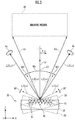
- FIG. 1 is a configuration diagram of a single-axis (single-dimensional) scanning type optical scanning apparatus 1.
- the optical scanning apparatus as a single-axis scanning type optical scanning apparatus, comprises a single-axis scanning type optical deflector 3.
- the optical scanning apparatus 1 includes an optical source 2, optical sensors 4a, 4b and a control unit 5.
- the optical source 2 is a laser source.
- the optical source 2 emits a light La.
- the light La enters a front surface of a mirror part 30, as an incident light of the optical deflector 3.
- the front surface of the circular mirror part 30 is constituted by a flat reflection surface 38 that occupies a great portion and a square grooved reflection surface 39 that occupies a small central portion containing a center O.
- the light that is of the light La and that enters the flat reflection surface 38 is emitted from the flat reflection surface 38, as a scanning light Lb.
- the light that is of the light La and that enters the grooved reflection surface 39 is emitted from the grooved reflection surface 39, as a detection light Lc.
- the detection light Lc includes a one-time reflected light L1, a two-time reflected light L2 and a three-time reflected light L3 ( FIG. 2 ).
- the optical sensors 4a, 4b are disposed on both sides of the optical deflector 3, so as not to be on the optical path of the scanning light Lb.
- the optical sensors 4a, 4b receive the two-time reflected light L2 emitted from the optical deflector 3 to both sides.
- the two-time reflected light L2 will be described in detail with FIG. 2 .
- the control unit 5 comprises a control apparatus 51, an optical source drive apparatus 52 and an actuator drive apparatus 53.
- the optical source drive apparatus 52 and the actuator drive apparatus 53 drive the optical source 2 and an actuator 32 of the optical deflector 3 respectively.
- the actuator 32 of the optical deflector 3 controls the reciprocal turning of the mirror part 30 about a rotation axis 36.
- the control apparatus 51 synchronously controls the drive of the optical source 2 and the drive of the actuator 32, based on detection signals from the optical sensors 4.
- the single-axis scanning type optical deflector 3 is the same as a known single-axis type piezoelectric optical deflector (e.g. JP P2014-056020A ), except the mirror part 30. Accordingly, the optical deflector 3 will be briefly described.
- a three-axis orthogonal coordinate system with an X-axis, a Y-axis and a Z-axis is defined for convenience of the description of the configuration of the optical deflector 3.
- the rotation axis 36 passes through the center O of the mirror part 30, and extends in the Y-axis direction.
- a torsion bar 31a and torsion bar 31b extend out of sides of the mirror part 30 along the rotation axis 36.
- Each of actuators 32a to 32d extends in the X-axis direction.
- the actuators 32a, 32b are disposed on both sides of the torsion bar 31a in the X-axis direction, and are interposed between the torsion bar 31a and a support frame 33.
- the actuators 32c, 32d are disposed on both sides of the torsion bar 31b in the X-axis direction, and are interposed between the torsion bar 31b and a support frame 33.
- the mirror part 30 has a circular shape of 1 mm ⁇ to 2 mm ⁇ .
- the grooved reflection surface 39 has a square shape, and the length of a side is several tens of micrometers to several hundreds of micrometers.
- the actuator 32 reciprocally turns a portion joined to the torsion bar 31 about the rotation axis 36. Thereby, the torsional vibration of the torsion bar 31 is transmitted to the mirror part 30, and the mirror part 30 is reciprocally turned about the rotation axis 36 at a predetermined resonance frequency. As a result, the scanning light Lb is reciprocally displaced in a deflection width Wb
- FIG. 2 is an explanatory diagram of the detection light Lc.
- a deflection angle ⁇ of the mirror part 30 about the rotation axis 36 and an emission angle ⁇ of the scanning light Lb and detection light Lc from the optical deflector 3 are defined.
- "Mirror perpendicular plane” is defined as a plane that contains the rotation axis 36 and that is perpendicular to the flat reflection surface 38.
- a mirror perpendicular plane 43 in FIG. 2 is defined as a mirror perpendicular plane when the mirror part 30 faces the front.
- the deflection angle ⁇ of the mirror part 30 is defined as the inclination angle of the mirror perpendicular plane with respect to the mirror perpendicular plane 43.
- the emission angle ⁇ is defined as the emission angle of the scanning light Lb and the detection light Lc with respect to the mirror perpendicular plane 43.
- the + side and - side of the X-axis with respect to the mirror perpendicular plane 43 are defined as the + side and the - side respectively.
- the grooved reflection surface 39 has a plurality of longitudinal grooves 41 whose longitudinal direction is parallel to the rotation axis 36.
- the longitudinal groove 41 is formed as a V-groove. That is, the longitudinal groove 41 contains the whole of the V-groove.
- a longitudinal groove 71 ( FIG. 11 ) described later is formed as a portion of the V-groove in which a bottom portion is cut off from the whole of the V-groove.
- the whole of the V-groove naturally contains the portion of the V-groove, and therefore each of the longitudinal grooves 41, 71 has a common structure of comprising a facing inclination surface that has at least an opening-side portion of a facing inclination surface of the V-groove.
- Each longitudinal groove 41 has facing inclination surfaces 42a, 42b.
- the facing inclination surfaces 42a, 42b are also the facing inclination surfaces of the V-groove, and are joined to each other at a bottom edge corresponding to a closing edge of the V-groove, so as to form a trough line.
- the detection light Lc is classified into the one-time reflected light L1, the two-time reflected light L2 and the three-time reflected light L3, according to the number of reflections in the longitudinal groove 41.
- the emission angles ⁇ of the one-time reflected light L1 and the three-time reflected light L3 vary in the deflection widths W1, W3, with the reciprocal turning of the mirror part 30 about the rotation axis 36.
- the emission angle ⁇ of the two-time reflected light L2 has a deflection width of 0, and is fixed regardless of the deflection angle ⁇ of the mirror part 30 about the rotation axis 36.
- the scanning light Lb is a light that is emitted from the mirror part 30 by the reflection of the light La on the flat reflection surface 38 of the mirror part 30.
- the scanning light Lb performs scanning in the X-axis direction on a drawing region 45 that is set on a screen or the like. Since the mirror part 30 is reciprocally turned about the rotation axis 36 as the single axis, the scanning of the scanning light Lb on the drawing region 45 is a single-dimensional scanning.
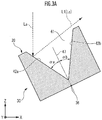
- FIG. 3A is an explanatory diagram of the one-time reflected light L1.
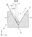
- FIG. 3B is an explanatory diagram of the two-time reflected light L2 and the three-time reflected light L3.
- FIG. 3A , FIG. 3B and FIG. 4 described later illustrates a longitudinal groove 41 that is of the plurality of longitudinal grooves 41 arrayed in the lateral direction and that is formed on the front surface side of the rotation axis 36.
- FIG. 3A and FIG. 3B shows only light that is of the light La and that enters the facing inclination surface 42a.
- the one-time reflected light L1, two-time reflected light L2 and three-time reflected light L3 derived from the light La that enters the facing inclination surface 42b are emitted in directions symmetrical to emission directions of the one-time reflected light L1, two-time reflected light L2 and three-time reflected light L3 in FIG. 3A and FIG. 3B .
- a groove center plane 47 is defined as a plane that contains the trough line of the longitudinal groove 41 and that is perpendicular to the plane of the flat reflection surface 38.
- the groove center plane 47 is defined for each longitudinal groove 41, and is parallel to the mirror perpendicular plane 43 when the deflection angle ⁇ of the mirror part 30 is 0.
- inclination angles ⁇ a, ⁇ b are shown as intersection angles between the facing inclination surfaces 42a, 42b with respect to the groove center plane 47.
- the inclination angles ⁇ a, ⁇ b will be described later with FIG. 6A and the like.
- inclination angles of the facing inclination surfaces 42a, 42b inclination angles ⁇ a, ⁇ b are defined (see FIG. 10 ), in addition to the inclination angles ⁇ a, ⁇ b.
- the inclination angles ⁇ a, ⁇ b are inclination angles of the facing inclination surfaces 42a, 42b with respect to a trough bottom plane 62 ( FIG. 10 ).
- an inclination angle ⁇ is used.
- an inclination angle ⁇ is used.
- the inclination angle ⁇ + the inclination angle ⁇ 90°.
- the inclination angle ⁇ and the inclination angle ⁇ are referred to as an inner angle side inclination angle and an outer angle side inclination angle respectively.
- the one-time reflected light L1 ( FIG. 3A ) is reflected one time by the facing inclination surface 42a, and thereafter is emitted from the longitudinal groove 41 to the + side in the X-axis direction.
- the two-time reflected light L2 ( FIG. 3B ) is reflected in the longitudinal groove 41 two times by the facing inclination surface 42a and the facing inclination surface 42b in this order, and thereafter is emitted from the longitudinal groove 41 to the - side in the X-axis direction.
- the three-time reflected light L3 ( FIG. 3A ) is reflected one time by the facing inclination surface 42a, and thereafter is emitted from the longitudinal groove 41 to the + side in the X-axis direction.
- the two-time reflected light L2 ( FIG. 3B ) is reflected in the longitudinal groove 41 two times by the facing inclination surface 42a and the facing inclination surface 42b in this order, and thereafter is emitted from the longitudinal groove 41 to the - side in
- the facing inclination surface 42a is divided into three segments of a first segment, a second segment and a third segment in order from an opening edge to a closing edge in the longitudinal groove 41.
- the one-time reflected light L1 is the reflected light of the light La that enters the first segment.
- the two-time reflected light L2 is the reflected light of the light La that enters the second segment.
- the three-time reflected light L3 is the reflected light of the light La that enters the third segment.
- FIG. 4 shows the relation of the deflection angle ⁇ of the mirror part 30 about the rotation axis 36 and the respective emission angles ⁇ of the one-time reflected light L1, the two-time reflected light L2 and the three-time reflected light L3.
- a case where the outer angle side inclination angles ⁇ a, ⁇ b of the V-groove is 54.7° is shown.
- the emission angles ⁇ of the one-time reflected light L1 and the three-time reflected light L3 from the optical deflector 3 changes in the deflection widths W1, W3, due to the reciprocal turning of the mirror part 30 about the rotation axis 36.
- the emission angle ⁇ of the two-time reflected light L2 from the optical deflector 3 is fixed at 38.8°, despite the reciprocal turning of the mirror part 30 about the rotation axis 36.
- FIG. 5 is a graph showing the relation of the deflection angle ⁇ of the mirror part 30 and the emission angles ⁇ of the reflected lights L1 to L3 from the optical deflector 3.
- the broken line, the solid line and the dotted line show relations for the one-time reflected light L1, the two-time reflected light L2 and the three-time reflected light L3, respectively.
- the one-time reflected light L1 and the three-time reflected light L3 change depending on the deflection angle ⁇ .
- the absolute value of the emission angle ⁇ of the two-time reflected light L2 is fixed at about 38.8°, for both the two-time reflected light L2 on the - side and the two-time reflected light L2 on the + side.
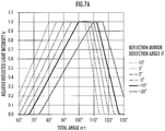
- ⁇ a + ⁇ b 110° is shown.
- the relative reflected light intensity Ir means a rate when the maximum intensity of the two-time reflected light L2 is 1.
- FIG. 6A and FIG. 6B show characteristics of the two-time reflected light L2 on the + side and the - side respectively.
- FIG. 7A shows a characteristic of the two-time reflected light L2 on the - side.
- FIG. 7B shows a characteristic of the two-time reflected light L2 on the + side.
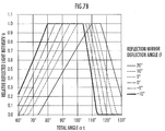
- a range of ⁇ t 80° to 120°, particularly, a range of about 100° to about 110° is advantageous in the increase in the relative intensity of the two-time reflected light L2 when the mirror part 30 is deflected in a ⁇ symmetrical manner with respect to the mirror perpendicular plane 43.
- FIG. 8A and FIG. 8B are explanatory diagrams of the interference of the two-time reflected light L2.
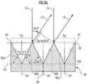
- An opening plane 59 is defined as a plane that contains ridge lines as upper edges of all longitudinal grooves 41 of the grooved reflection surface 39.
- the trough bottom plane 62 is defined as a plane that contains trough bottoms as lower edges of all longitudinal grooves 41 of the grooved reflection surface 39.
- the deflection angle ⁇ of the grooved reflection surface 39 is 0° in FIG. 8A , and is ⁇ 1 (> 0°) in FIG. 8B .
- the Miller indices of the principal surface of the normal silicon substrate are (100).
- an alkaline aqueous solution such as KOH (potassium hydroxide), TMAH (tetramethylammonium hydroxide) and EDP (ethylenediamine pyrocatechol) is used as the etchant for the anisotropic etching, and thereby the (111) plane for the facing inclination surfaces 42a, 42b can be selectively formed.
- KOH potassium hydroxide
- TMAH tetramethylammonium hydroxide
- EDP ethylenediamine pyrocatechol
- the emission angle ⁇ of the two-time reflected light L2 from the optical deflector 3 is 38.8° regardless of the deflection angle ⁇ , as described above with FIG. 4 .
- Dp is a pitch that is a regular lateral interval of the longitudinal groove 41 of the grooved reflection surface 39.
- the two-time reflected light L2 has a property of (a) the emission angle ⁇ from the optical deflector 3 is constant regardless of the deflection angle ⁇ of the mirror part 30, and a property of (b) the intensity of the two-time reflected light L2 that is received by the optical sensor 4 changes depending on the deflection angle ⁇ of the mirror part 30 because the two-time reflected lights L2 from the plurality of longitudinal grooves 41 interfere with each other.
- the optical sensor 4 is constituted by a PD (Photo Diode).
- PD Photo Diode
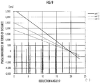
- phase difference ⁇ (in terms of distance) between the two-time reflected lights L2 from adjacent longitudinal grooves 41 is calculated from Expression 1 in the case of FIG. 8A , and is calculated from Expression 2 in the case of FIG. 8B .
- Phase Difference ⁇ Dp ⁇ sin 38.8 °
- Phase Difference ⁇ Dp ⁇ sin 38.8 ° ⁇ ⁇ 1 ⁇ Dp ⁇ sin ⁇ 1
- FIG. 9 is a graph showing the relation of the phase difference ⁇ and the deflection angle ⁇ of the mirror part 30 when three combinations of the pitch Dp and a wavelength ⁇ are used as parameters.
- the inclination angle ⁇ of the facing inclination surface 42 is 54.7°.
- the values of the pitch Dp and the wavelength ⁇ in each combination are as follows.
- the optical scanning apparatus 1 comprises two optical sensors 4 in total, on both sides in the X-axis direction. Thereby, it is possible to expand the detection range for the deflection angle ⁇ of the mirror part 30. Furthermore, in the case of the deflection angle ⁇ ⁇ 0°, the light entering quantity of the light La is larger on the facing inclination surface 42a than on the facing inclination surface 42b, and the light receiving quantity of the two-time reflected light L2 is larger on the optical sensor 4b than on the optical sensor 4a.
- the light entering quantity of the light La is larger on the facing inclination surface 42b than on the facing inclination surface 42a, and the light receiving quantity of the two-time reflected light L2 is larger on the optical sensor 4a than on the optical sensor 4b.
- the deflection angle ⁇ may be detected based on the output of the optical sensor 4a, and in the case of the deflection angle ⁇ ⁇ 0°, the deflection angle ⁇ may be detected based on the output of the optical sensor 4b. Thereby, it is possible to increase the detection accuracy for the deflection angle ⁇ .
- the following method may be adopted instead of switching the optical sensor 4 to be used from the plurality of optical sensors 4 depending on the deflection angle ⁇ .
- the average of the deflection angles ⁇ detected by the optical sensors 4 is determined as the deflection angle ⁇ that is the final result.
- the deflection angle ⁇ may be detected from the total of the outputs of the optical sensors 4.
- FIG. 10 is an explanatory diagram about a prevention measure for the three-time reflected light L3.
- the opening plane 59 and the trough bottom plane 62 are defined with FIG. 8A .
- a convex portion with an inverse V-shaped section is formed at a regular lateral interval (Dp), by adjacent facing inclination surfaces 42b, 42a between laterally adjacent longitudinal grooves 41.
- the ridge line of the grooved reflection surface 39 is the tip of the convex portion with that inverse V-shaped section that is formed on the front surface side of the grooved reflection surface 39.
- the opening plane 59 is a plane that contains the plurality of ridge lines, and is in the same plane as the flat reflection surface 38.
- a cut plane 60 is a plane parallel to the opening plane 59, and traverses the facing inclination surfaces 42 at an intermediate position in the depth direction.
- Intersection lines 61a, 61b are intersection lines between the cut plane 60 and the longitudinal grooves 41a, 41b.
- Each facing inclination surface 42 is divided along the cut plane 60 into an opening-side portion Fa and a closing-side portion Fb.
- the first to third segments have been described above with FIG. 3A and FIG. 3B .
- the opening-side portion Fa corresponds to a segment resulting from combining the first segment and the second segment.
- the closing-side portion Fb corresponds to the third segment.
- the first segment, the second segment and the third segment are segments where the lights La to generate the one-time reflected light L1, the two-time reflected light L2 and the three-time reflected light L3 are firstly reflected, respectively.
- Da denotes the length of the opening-side portion Fa on a transverse section of the longitudinal groove 41.
- Db denotes the length of the closing-side portion Fb on the transverse section of the longitudinal groove 41.
- Dc denotes the X-axis directional size of an interval between the intersection line 61b and the intersection line 61a that are adjacent in the X-axis direction on the transverse section of the longitudinal groove 41 in the relation of the - side and the + side.
- Dd denotes the X-axis directional size of an interval between the intersection line 61a and the intersection line 61b that are adjacent in the X-axis direction in the relation of the - side and the + side.
- De and Df denote the sizes of the opening-side portion Fa and the closing-side portion Fb in the Z-axis direction (the depth direction of the longitudinal groove 41).
- FIG. 11 shows a transverse section of a grooved reflection surface 69 having a measure against the three-time reflected light L3.
- a facing inclination surface 72 of a longitudinal groove 71 of the grooved reflection surface 69 has a structure in which the closing-side portion Fb is eliminated from the facing inclination surface 42 of the longitudinal groove 41 of the grooved reflection surface 39 ( FIG. 10 ) and only the opening-side portion Fa is left.
- the plurality of longitudinal grooves 71 of the grooved reflection surface 69 is arranged such that the longitudinal direction is parallel to the rotation axis 36.
- the length of the facing inclination surface 72 is set to Da ( FIG. 10 ).
- Each longitudinal groove 71 has a trough-side opening 75 on the back surface side.
- a concavity 77 is formed on the back surface side of the grooved reflection surface 69, and the trough-side openings 75 commonly communicate with the concavity 77.
- the grooved reflection surface 69 As a result, on the grooved reflection surface 69, the light La that is of the light La and that enters the closing-side portion Fb (the third segment) of the grooved reflection surface 39 ( FIG. 3 ) goes from the trough-side opening 75 to the back surface side of the mirror part 30. Accordingly, on the grooved reflection surface 69, the generation of the three-time reflected light L3 that overlaps the two-time reflected light L2 is inhibited.
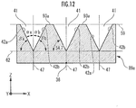
- FIG. 12 is a sectional view of a grooved reflection surface 89a in which a part of the structure of the grooved reflection surface 39 in FIG. 8A is altered. Corresponding elements between the grooved reflection surface 89a and the grooved reflection surface 39 are denoted by identical reference characters.
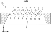
- FIG. 13 is a sectional view of a grooved reflection surface 89b in which a part of the structure of the grooved reflection surface 69 in FIG. 11 is altered.
- Corresponding elements between the grooved reflection surface 89b and the grooved reflection surface 69 are denoted by identical reference characters.
- a two-axis (two-dimensional) scanning type optical scanning apparatus 101 comprises a two-axis scanning type optical deflector 103, as two-axis scanning type optical scanning apparatus.
- elements in common with the optical scanning apparatus 1 are denoted by reference characters identical to the reference characters assigned to the elements of the optical scanning apparatus 1, and descriptions thereof are omitted.
- optical scanning apparatus 101 comprises an optical deflector 103 and an optical sensor 104 instead of the optical deflector 3 and optical sensor 4 of the optical scanning apparatus 1.
- optical deflector 103 and the optical sensor 104 will be described below.
- the optical deflector 103 has the same configuration as a known two-axis type piezoelectric optical deflector (e.g. JP P2017-207630A ), except a mirror part 130. Details of the mirror part 130 will be described later. The structure of the optical deflector 103 will be briefly described.
- a known two-axis type piezoelectric optical deflector e.g. JP P2017-207630A
- the optical deflector 103 comprises the mirror part 130, torsion bars 131a, 131b, inner actuators 145a, 145b, a movable frame 146, outer actuators 147a, 147b, and a fixed frame 148.
- a first rotation axis 136 and a second rotation axis 137 each are set on the surface of the optical deflector 103, and are orthogonal at the center O of the mirror part 130.
- the first rotation axis 136 coincides with a central axis line of the torsion bar 131.
- the first rotation axis 136 and the second rotation axis 137 are in the Y-axis direction and the X-axis direction respectively.
- the inner actuator 145 performs the torsional vibration of the torsion bar 131 about the first rotation axis 136 at a resonance frequency. Thereby, the mirror part 130 is reciprocally turned about the first rotation axis 136 at a resonance frequency F1.
- the outer actuator 147 reciprocally turns the movable frame 146 about an axis line parallel to the X-axis, at a non-resonance frequency F2 (F2 ⁇ F1). Thereby, the mirror part 130 is reciprocally turned about the second rotation axis 137.
- the mirror part 130 is reciprocally turned about the two axes of the first rotation axis 136 and the second rotation axis 137, unlike the mirror part 30, but the structure is the same as the structure of the mirror part 30. That is, on the front surface, the mirror part 130 has a flat reflection surface 138 and a grooved reflection surface 139 that are the same as the flat reflection surface 38 and grooved reflection surface 39 of the mirror part 30 respectively.
- a deflection angle ⁇ h is defined as the deflection angle of the mirror part 130 about the first rotation axis 136
- a deflection angle ⁇ v is defined as the deflection angle of the mirror part 130 about the second rotation axis 137.
- a deflection angle ⁇ h is defined as the deflection angle of the mirror part 130 about the first rotation axis 136
- a deflection angle ⁇ v is defined as the deflection angle of the mirror part 130 about the second rotation axis 137.
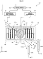
- the optical sensors 104a, 104b are disposed so as not to be on the optical path of the scanning light Lb for two-dimensional scanning. Specifically, the optical sensors 104a, 104b are disposed on both sides in the X-axis direction with respect to the emission range of the scanning light Lb, and receive two-time reflected lights L2 on the respective sides in the X-axis direction. Each optical sensor 104 detects the deflection angle ⁇ h of the mirror part 130 about the first rotation axis 136.
- the mirror part 130 is reciprocally turned about the second rotation axis 137. Accordingly, the two-time reflected light L2 is displaced in the Y-axis direction to perform scanning, due to the reciprocal turning of the mirror part 130 about the second rotation axis 137, though the emission direction of the two-time reflected light L2 from the mirror part 130 is constant regardless of the deflection angle ⁇ h of the mirror part 130 about the first rotation axis 136. Therefore, the length of each optical sensor 104 is set such that the optical sensor 104 extends along the scanning trajectory of the two-time reflected light L2 in the Y-axis direction.
- FIG. 15 is a configuration diagram of an optical scanning apparatus 161 in which the optical scanning apparatus 101 in FIG. 14 is modified.
- the difference of the optical scanning apparatus 161 from the optical scanning apparatus 101 is a grooved reflection surface 169 of the mirror part 130.
- the grooved reflection surface 169 the grooved reflection surface 139 of the optical scanning apparatus 101 is rotated by 90° clockwise about a standing line at the center O that is perpendicular to the flat reflection surface 138.
- the two-time reflected light L2 from the grooved reflection surface 169 is emitted to both sides in the Y-axis direction with respect to the emission range of the scanning light Lb that is emitted for two-dimensional scanning.
- the optical sensors 164a, 164b are disposed on both sides in the Y-axis direction with respect to the emission range of the scanning light Lb, and receive the two-time reflected lights L2 on the respective sides in the Y-axis direction.
- the light receiving quantity (or the relative reflected light intensity Ir) of each optical sensor 164 changes depending on the deflection angle ⁇ v of the mirror part 130.
- the control apparatus 51 detects the deflection angle ⁇ v of the mirror part 130 based on the output from each optical sensor 164.
- the mirror part 130 is reciprocally turned about the second rotation axis 137. Accordingly, the two-time reflected light L2 is displaced in the X-axis direction to perform scanning, due to the reciprocal turning of the mirror part 130 about the first rotation axis 136, though the emission angle of the two-time reflected light L2 from the mirror part 130 is fixed regardless of the deflection angle ⁇ v of the mirror part 130 about the second rotation axis 137. Therefore, the length of each optical sensor 164 is set such that the optical sensor 164 extends along the scanning trajectory of the two-time reflected light L2 in the X-axis direction.
- the deflection angle ⁇ v of the non-resonance vibration of the mirror part 130 about the second rotation axis 137 is detected from the light receiving quantity (or the relative reflected light intensity Ir) of the two-time reflected light L2 of the optical sensor 164.
- the first rotation axis in the present invention corresponds to the rotation axis 36 and the first rotation axis 136.
- the second rotation axis in the present invention corresponds to the second rotation axis 137.
- the first actuator in the present invention corresponds to the actuator 32 and the inner actuator 145.
- the second actuator in the present invention corresponds to the outer actuator 147.
- the first actuator and second actuator in the embodiment each are piezoelectric actuators, but the first actuator and second actuator in the present invention may be electromagnetic coil actuators or electrostatic actuators.
- the first rotation axis direction and second rotation axis direction in the present invention corresponds to the Y-axis direction and X-axis direction in the embodiment.
- the deflection angle ⁇ of the mirror part 30, 130 may be detected by providing the grooved reflection surface 39, 139 only on one side in the X-axis direction with respect to the center O and providing the optical sensor 4, 104 only on the other side in the X-axis direction with respect to the optical deflector 3, 103.
- the grooved reflection surface 39, 139 may be provided on both one side and the other side with respect to the center O of the mirror part 30, such that the optical sensor 4 on the other side receives the two-time reflected light L2 from the grooved reflection surface 39, 139 on the one side and the optical sensor 4 on the one side receives the two-time reflected light L2 from the grooved reflection surface 39, 139 on the other side.
- the Miller indices of the principal surface are (100), and the Miller indices of the facing inclination surface 42 are (111).
- the Miller indices of the principal surface may be (111) and the Miller indices of the facing inclination surface 42 may be (100), in the silicon crystal layer of the substrate.
- the flat reflection surface 38, 138 and the grooved reflection surface 39, 69, 89a, 89b, 139 are formed as a mirror surface layer that covers the common substrate layer of the mirror part 30, 130.
- the mirror surface layer is constituted by a silicon crystal surface and a metal reflection film or dielectric multilayer film.
Landscapes
- Physics & Mathematics (AREA)
- General Physics & Mathematics (AREA)
- Optics & Photonics (AREA)
- Engineering & Computer Science (AREA)
- Electromagnetism (AREA)
- Computer Hardware Design (AREA)
- Theoretical Computer Science (AREA)
- Micromachines (AREA)
- Mechanical Optical Scanning Systems (AREA)
- Mechanical Light Control Or Optical Switches (AREA)
Abstract
Description
- The present invention relates to an optical deflector and an optical scanning apparatus.
- There are known an optical deflector for MEMS (Micro Electro Mechanical Systems) and an optical scanning apparatus comprising the optical deflector (e.g.
JP P2006-243225A JP P2011-118178A - The scanning range and scanning position of the scanning light change depending on the deflection angle of the mirror part. Accordingly, it is necessary to detect the deflection angle of the mirror part for properly controlling the scanning light in the scanning range.
- An optical scanning apparatus in
JP P2006-243225A - In an optical scanning apparatus in
JP P2011-118178A - The optical scanning apparatus in
JP P2006-243225A - The optical scanning apparatus in
JP P2011-118178A - An object of the present invention is to provide an optical deflector and an optical scanning apparatus that can detect an arbitrary deflection angle of the mirror part while avoiding the increase in the length of the optical sensor for the detection of the deflection angle.
- An optical deflector of the present invention comprises:
- a mirror part that has a flat reflection surface and a grooved reflection surface, each of the flat reflection surface and the grooved reflection surface reflecting an incident light; and
- a first actuator that reciprocally turns the mirror part about a first rotation axis, wherein
- the grooved reflection surface has a plurality of longitudinal grooves that extends parallel to the first rotation axis, and
- each longitudinal groove has a facing inclination surface that is parallel to the first rotation axis and that has at least an opening-side portion of a facing inclination surface of a V-groove.
- According to the present invention, the optical deflector comprises the grooved reflection surface on the mirror part, and emits a two-time reflected light from the grooved reflection surface. The emission direction of the two-time reflected light about the first rotation axis is fixed regardless of the deflection angle of the mirror part about the first rotation axis. Further, two-time reflected lights from the longitudinal grooves of the grooved reflection surface interfere with each other, and therefore the intensity of the two-time reflected light changes depending on the deflection angle of the mirror part.
- Thus, it is possible to detect an arbitrary deflection angle of the mirror part while avoiding the increase in the length of the optical sensor for the detection of the deflection angle.
- Preferably, in the optical deflector of the present invention, both facing inclination surfaces of the V-groove may have inclination angles that are equal to each other with respect to a reference bottom plane, the reference bottom plane passing through a trough line of the V-groove and being parallel to the flat reflection surface.
- According to this configuration, it is possible to increase the intensity of the two-time reflected light.
- Preferably, in the optical deflector of the present invention, the facing inclination surfaces of the longitudinal groove may have a shape in which a bottom portion of the V-groove is cut off.
- According to this configuration, the facing inclination surfaces of the longitudinal groove form the shape in which a bottom portion of the V-groove is cut off. Thereby, it is possible to restrain the generation of a three-time reflected light, and to prevent the three-time reflected light from overlapping the two-time reflected light and obstructing the detection of the deflection angle of the mirror part by the two-time reflected light.
- Preferably, in the optical deflector of the present invention,
a cut plane that passes through the V-groove parallel to the flat reflection surface at an intermediate position in a depth direction of the V-groove may be defined,
the facing inclination surface of the V-groove may be divided along the cut plane into an opening-side portion and a closing-side portion, the opening-side portion being a portion on an opening side of the V-groove, the closing-side portion being a portion on a closing side of the V-groove,
lengths of the opening-side portion and the closing-side portion on a transverse section of the V-groove may be Da and Db respectively,
the inclination angle of the V-groove with respect to the reference bottom plane may be β,
the cut plane may satisfy a condition of Da : Db = |tan(2·β)| : |tan(β)|, and
the facing inclination surface of the longitudinal groove may have a shape in which the closing-side portion is cut off from the V-groove, as the shape in which the bottom portion of the V-groove is cut off. - According to this configuration, it is possible to clearly show the position where the bottom portion of the V-groove is cut off.
- Preferably, in the optical deflector of the present invention, the sum of the inclination angles of both facing inclination surfaces of the V-groove with respect to the reference bottom surface may be in a range of 80° to 120°.
- According to this configuration, it is possible to increase the intensity of the two-time reflected light.
- Preferably, in the optical deflector of the present invention,
the mirror part may have the flat reflection surface and the grooved reflection surface on a surface of a common substrate layer formed of a crystal layer of silicon, and - Miller indices of a principal surface of the crystal layer and the facing inclination surface of the longitudinal groove may be one and the other of (100) and (111) respectively.
- According to this configuration, it is possible to easily produce the facing inclination surface having a desired inclination angle, using Miller indices of crystal planes of silicon, while securing the flat reflection surface and the grooved reflection surface that have suitable mirror surfaces.
- Preferably, in the optical deflector of the present invention, the inclination angle of each facing inclination surface with respect to the reference bottom plane may be 54.7°.
- According to this configuration, it is possible to simplify the formation of a desired inclination angle, by setting the inclination angle of each facing inclination surface with respect to the reference bottom plane to the intersection angle between (100) and (111) that are Miller indices of the silicon crystal layer.
- Preferably, in the optical deflector of the present invention, the grooved reflection surface may be provided on the first rotation axis, and the first actuator may be a piezoelectric actuator, an electrostatic actuator or an electromagnetic actuator.
- According to this configuration, it is possible to equalize the intensity of the two-time reflected light when the mirror part is deflected to one side with respect to the front face of the optical deflector and the intensity of the two-time reflected light when the mirror part is deflected to the other side.
- Preferably, in the optical deflector of the present invention, the grooved reflection surface may be provided at a central portion of the mirror part.
- According to this configuration, it is possible to downsize the grooved reflection surface.
- An optical scanning apparatus of the present invention comprises:
- the above-described optical deflector;
- an optical source that generates the incident light, the incident light entering the mirror part; and
- an optical sensor that receives a two-time reflected light, the two-time reflected light being emitted after the incident light is reflected in the longitudinal groove of the grooved reflection surface of the mirror part two times.
- According to the optical scanning apparatus of the present invention, it is possible to detect an arbitrary deflection angle of the mirror part while avoiding the increase in the length of the optical sensor for the detection of the deflection angle.
- Preferably, in the optical scanning apparatus, the optical sensor may be provided on both sides of a perpendicular reference plane that passes through a center of the mirror part perpendicularly to the flat reflection surface when the mirror part has a central deflection angle in a deflection width about the first rotation axis.
- According to this configuration, it is possible to properly detect the deflection angle even when the mirror part is deflected to one side with respect to the center in the deflection width about the first rotation axis.
- Preferably, in the optical scanning apparatus of the present invention,
the optical deflector may comprise a second actuator that reciprocally turns the mirror part about a second rotation axis orthogonal to the first rotation axis, and
the optical sensor may extend along a scanning trajectory of scanning of the two-time reflected light from the mirror part when the mirror part is reciprocally turned about the second rotation axis. - According to this configuration, with the optical sensor, it is possible to properly detect the deflection angle of the mirror part about the first rotation axis in a two-axis scanning type optical deflector.
- Another optical deflector of the present invention comprises:
- a mirror part that has a flat reflection surface and a grooved reflection surface, each of the flat reflection surface and the grooved reflection surface reflecting an incident light;
- a first actuator that reciprocally turns the mirror part about a first rotation axis; and
- a second actuator that reciprocally turns the mirror part about a second rotation axis orthogonal to the first rotation axis, wherein
- the grooved reflection surface has a plurality of longitudinal grooves that extends parallel to the second rotation axis, and
- each longitudinal groove has a facing inclination surface that is parallel to the second rotation axis and that has at least an opening-side portion of a facing inclination surface of a V-groove.
- According to the present invention, in a two-axis scanning type optical deflector, it is possible to detect an arbitrary deflection angle of the mirror part about the second rotation axis, using the two-time reflected light from the grooved reflection surface.
- Preferably, in another optical deflector of the present invention,
both facing inclination surfaces of the V-groove may have inclination angles that are equal to each other with respect to a reference bottom plane, the reference bottom plane passing through a trough line of the V-groove and being parallel to the flat reflection surface,
the facing inclination surface of the longitudinal groove may have a shape in which a bottom portion of the V-groove is cut off,
a cut plane that passes through the V-groove parallel to the flat reflection surface at an intermediate position in a depth direction of the V-groove may be defined,
the facing inclination surface of the V-groove may be divided along the cut plane into an opening-side portion and a closing-side portion, the opening-side portion being a portion on an opening side of the V-groove, the closing-side portion being a portion on a closing side of the V-groove,
lengths of the opening-side portion and the closing-side portion on a transverse section of the V-groove may be Da and Db respectively,
the inclination angle of the V-groove with respect to the reference bottom plane may be β,
the cut plane may satisfy a condition of Da : Db = |tan(2·β)| : |tan(β)|, and
the facing inclination surface of the longitudinal groove may have a shape in which the closing-side portion is cut off from the V-groove, as the shape in which the bottom portion of the V-groove is cut off. - According to this configuration, in the detection of the deflection angle of the mirror part about the second rotation axis, it is possible to avoid the three-time reflected light from overlapping the two-time reflected light. Further, it is possible to clearly show the position where the bottom part of the V-groove is cut off.
- An another optical scanning apparatus of the present invention comprises:
- another optical deflector;
- an optical source that generates the incident light, the incident light entering the mirror part; and
- an optical sensor that receives a two-time reflected light, the two-time reflected light being emitted after the incident light is reflected in the longitudinal groove of the grooved reflection surface of the mirror part two times, the optical sensor extending along a scanning trajectory of scanning of the two-time reflected light when the mirror part is reciprocally turned about the first rotation axis.
- According to the present invention, in a two-axis scanning type optical scanning apparatus, it is possible to detect an arbitrary deflection angle of the mirror part about the second rotation axis while avoiding the increase in the length of the optical sensor for the detection of the deflection angle.
- Preferably, in the optical scanning apparatus of the present invention, the optical sensor may be provided on both sides of the optical deflector in a direction of the second rotation axis.
- According to this configuration, it is possible to properly detect the deflection angle even when the mirror part is deflected to one side with respect to the center of the deflection angle range about the second rotation axis.
- The embodiments herein will be better understood from the following detailed description with reference to the drawings, in which:
-
FIG. 1 is a configuration diagram of a single-axis (single-dimensional) scanning type optical scanning apparatus; -
FIG. 2 is an explanatory diagram of a detection light; -
FIG. 3A is an explanatory diagram of a one-time reflected light; -
FIG. 3B is an explanatory diagram of a two-time reflected light and a three-time reflected light; -
FIG. 4 is a diagram showing the relation of the deflection angle of a mirror part about a rotation axis and the emission angle of each reflected light; -
FIG. 5 is a graph showing the relation of the deflection angle of amirror part 30 and the emission angle of each reflected light from longitudinal grooves; -
FIG. 6A is a graph showing the relation of a difference angle between inclination angles of facing inclination surfaces with respect to a groove center plane of the mirror part and a relative reflected light intensity for a two-time reflected light having a negative emission angle; -
FIG. 6B is a graph showing the relation of the difference angle between inclination angles of both facing inclination surfaces with respect to the groove center plane of the mirror part and the relative reflected light intensity for a two-time reflected light having a positive emission angle; -
FIG. 7A is a graph showing the relation of the total angle of inclination angles of both facing inclination surfaces with respect to a reference plane and the relative reflected light intensity for a two-time reflected light having an emission angle smaller than 0°; -
FIG. 7B is a graph showing the relation of the total angle of inclination angles of both facing inclination surfaces with respect to the reference plane and the relative reflected light intensity for a two-time reflected light having an emission angle equal to or larger than 0°; -
FIG. 8A is an explanatory diagram of the interference of the two-time reflected light when the mirror part has a deflection angle equal to 0°; -
FIG. 8B is an explanatory diagram of the interference of the two-time reflected light when the mirror part has a deflection angle larger than 0°; -
FIG. 9 is a diagram showing the relation of the deflection angle, the phase difference (inclination line) and the intensity (longitudinal bar) of a two-time reflected light L2 when the combination of the lateral pitch of longitudinal grooves on a grooved reflection surface and the wavelength of the incident light is variously altered; -
FIG. 10 is an explanatory diagram about a prevention measure for a three-time reflected light; -
FIG. 11 is a sectional view of the structure of a grooved reflection surface in which a bottom portion of a V-groove is cut off from facing inclination surfaces of the grooved reflection surface inFIG. 8A based on a predetermined expression; -
FIG. 12 is a sectional view of a grooved reflection surface in which a part of the structure of the grooved reflection surface inFIG. 8A is altered; -
FIG. 13 is a sectional view of a grooved reflection surface in which a part of the structure of the grooved reflection surface inFIG. 11 is altered; -
FIG. 14 is a configuration diagram of a two-axis scanning type optical scanning apparatus that can detect the deflection angle of the mirror part about a first rotation axis; and -
FIG. 15 is a configuration diagram of a two-axis scanning type optical scanning apparatus that can detect the deflection angle of the mirror part about a second rotation axis. - Preferred embodiments of the present invention will be described below. Naturally, the present invention is not limited to the embodiments described below. The present invention can be carried out as various embodiments within the scope of the technical idea disclosed in the specification. In the embodiments, common constituent elements are denoted by identical reference characters.
-
FIG. 1 is a configuration diagram of a single-axis (single-dimensional) scanning typeoptical scanning apparatus 1. Theoptical scanning apparatus 1, as a single-axis scanning type optical scanning apparatus, comprises a single-axis scanning typeoptical deflector 3. In addition to theoptical deflector 3, theoptical scanning apparatus 1 includes anoptical source 2,optical sensors control unit 5. - For example, the
optical source 2 is a laser source. Theoptical source 2 emits a light La. The light La enters a front surface of amirror part 30, as an incident light of theoptical deflector 3. In this example, the front surface of thecircular mirror part 30 is constituted by aflat reflection surface 38 that occupies a great portion and a squaregrooved reflection surface 39 that occupies a small central portion containing a center O. The light that is of the light La and that enters theflat reflection surface 38 is emitted from theflat reflection surface 38, as a scanning light Lb. The light that is of the light La and that enters the groovedreflection surface 39 is emitted from the groovedreflection surface 39, as a detection light Lc. The detection light Lc includes a one-time reflected light L1, a two-time reflected light L2 and a three-time reflected light L3 (FIG. 2 ). - The
optical sensors optical deflector 3, so as not to be on the optical path of the scanning light Lb. Theoptical sensors optical deflector 3 to both sides. The two-time reflected light L2 will be described in detail withFIG. 2 . - The
control unit 5 comprises acontrol apparatus 51, an opticalsource drive apparatus 52 and anactuator drive apparatus 53. The opticalsource drive apparatus 52 and theactuator drive apparatus 53 drive theoptical source 2 and an actuator 32 of theoptical deflector 3 respectively. For theoptical source 2, by the drive from the opticalsource drive apparatus 52, the lighting-up, the lighting-off and the light intensity at the time of the lighting-up are controlled. By the drive from theactuator drive apparatus 53, the actuator 32 of theoptical deflector 3 controls the reciprocal turning of themirror part 30 about arotation axis 36. Thecontrol apparatus 51 synchronously controls the drive of theoptical source 2 and the drive of the actuator 32, based on detection signals from the optical sensors 4. - The single-axis scanning type
optical deflector 3 is the same as a known single-axis type piezoelectric optical deflector (e.g.JP P2014-056020A mirror part 30. Accordingly, theoptical deflector 3 will be briefly described. A three-axis orthogonal coordinate system with an X-axis, a Y-axis and a Z-axis is defined for convenience of the description of the configuration of theoptical deflector 3. - The
rotation axis 36 passes through the center O of themirror part 30, and extends in the Y-axis direction. Atorsion bar 31a andtorsion bar 31b extend out of sides of themirror part 30 along therotation axis 36. Each ofactuators 32a to 32d extends in the X-axis direction. Theactuators torsion bar 31a in the X-axis direction, and are interposed between thetorsion bar 31a and asupport frame 33. Theactuators torsion bar 31b in the X-axis direction, and are interposed between thetorsion bar 31b and asupport frame 33. - For example, sizes of portions of the
mirror part 30 are as follows. Themirror part 30 has a circular shape of 1 mmφ to 2 mmφ. Thegrooved reflection surface 39 has a square shape, and the length of a side is several tens of micrometers to several hundreds of micrometers. - The actuator 32 reciprocally turns a portion joined to the torsion bar 31 about the
rotation axis 36. Thereby, the torsional vibration of the torsion bar 31 is transmitted to themirror part 30, and themirror part 30 is reciprocally turned about therotation axis 36 at a predetermined resonance frequency. As a result, the scanning light Lb is reciprocally displaced in a deflection width Wb -
FIG. 2 is an explanatory diagram of the detection light Lc. Hereinafter, for convenience of description, a deflection angle θ of themirror part 30 about therotation axis 36 and an emission angle γ of the scanning light Lb and detection light Lc from theoptical deflector 3 are defined. "Mirror perpendicular plane" is defined as a plane that contains therotation axis 36 and that is perpendicular to theflat reflection surface 38. A mirrorperpendicular plane 43 inFIG. 2 is defined as a mirror perpendicular plane when themirror part 30 faces the front. - In the single-axis type
optical deflector 3, the deflection angle θ of themirror part 30 is defined as the inclination angle of the mirror perpendicular plane with respect to the mirrorperpendicular plane 43. The emission angle γ is defined as the emission angle of the scanning light Lb and the detection light Lc with respect to the mirrorperpendicular plane 43. For each of the deflection angle θ and the emission angle γ, the + side and - side of the X-axis with respect to the mirrorperpendicular plane 43 are defined as the + side and the - side respectively. - The
grooved reflection surface 39 has a plurality oflongitudinal grooves 41 whose longitudinal direction is parallel to therotation axis 36. Thelongitudinal groove 41 is formed as a V-groove. That is, thelongitudinal groove 41 contains the whole of the V-groove. Meanwhile, a longitudinal groove 71 (FIG. 11 ) described later is formed as a portion of the V-groove in which a bottom portion is cut off from the whole of the V-groove. The whole of the V-groove naturally contains the portion of the V-groove, and therefore each of thelongitudinal grooves - Each
longitudinal groove 41 has facing inclination surfaces 42a, 42b. The facing inclination surfaces 42a, 42b are also the facing inclination surfaces of the V-groove, and are joined to each other at a bottom edge corresponding to a closing edge of the V-groove, so as to form a trough line. - The detection light Lc is classified into the one-time reflected light L1, the two-time reflected light L2 and the three-time reflected light L3, according to the number of reflections in the
longitudinal groove 41. As described later in detail, the emission angles γ of the one-time reflected light L1 and the three-time reflected light L3 vary in the deflection widths W1, W3, with the reciprocal turning of themirror part 30 about therotation axis 36. Meanwhile, the emission angle γ of the two-time reflected light L2 has a deflection width of 0, and is fixed regardless of the deflection angle θ of themirror part 30 about therotation axis 36. - In
FIG. 2 , the scanning light Lb is a light that is emitted from themirror part 30 by the reflection of the light La on theflat reflection surface 38 of themirror part 30. The scanning light Lb performs scanning in the X-axis direction on adrawing region 45 that is set on a screen or the like. Since themirror part 30 is reciprocally turned about therotation axis 36 as the single axis, the scanning of the scanning light Lb on thedrawing region 45 is a single-dimensional scanning. -
FIG. 3A is an explanatory diagram of the one-time reflected light L1.FIG. 3B is an explanatory diagram of the two-time reflected light L2 and the three-time reflected light L3. Each ofFIG. 3A ,FIG. 3B andFIG. 4 described later illustrates alongitudinal groove 41 that is of the plurality oflongitudinal grooves 41 arrayed in the lateral direction and that is formed on the front surface side of therotation axis 36. Each ofFIG. 3A andFIG. 3B shows only light that is of the light La and that enters the facinginclination surface 42a. The one-time reflected light L1, two-time reflected light L2 and three-time reflected light L3 derived from the light La that enters the facinginclination surface 42b are emitted in directions symmetrical to emission directions of the one-time reflected light L1, two-time reflected light L2 and three-time reflected light L3 inFIG. 3A andFIG. 3B . - A
groove center plane 47 is defined as a plane that contains the trough line of thelongitudinal groove 41 and that is perpendicular to the plane of theflat reflection surface 38. Thegroove center plane 47 is defined for eachlongitudinal groove 41, and is parallel to the mirrorperpendicular plane 43 when the deflection angle θ of themirror part 30 is 0. - In
FIG. 3A , inclination angles αa, αb are shown as intersection angles between the facing inclination surfaces 42a, 42b with respect to thegroove center plane 47. The inclination angles αa, αb will be described later withFIG. 6A and the like. - As inclination angles of the facing inclination surfaces 42a, 42b, inclination angles βa, βb are defined (see
FIG. 10 ), in addition to the inclination angles αa, αb. The inclination angles βa, βb are inclination angles of the facing inclination surfaces 42a, 42b with respect to a trough bottom plane 62 (FIG. 10 ). When the inclination angles αa, αb are collectively referred, an inclination angle α is used. When the inclination angles βa, βb are collectively referred, an inclination angle β is used. There is a relation of the inclination angle α + the inclination angle β = 90°. For discrimination between the inclination angle α and the inclination angle β, when necessary, the inclination angle α and the inclination angle β are referred to as an inner angle side inclination angle and an outer angle side inclination angle respectively. - The one-time reflected light L1 (
FIG. 3A ) is reflected one time by the facinginclination surface 42a, and thereafter is emitted from thelongitudinal groove 41 to the + side in the X-axis direction. The two-time reflected light L2 (FIG. 3B ) is reflected in thelongitudinal groove 41 two times by the facinginclination surface 42a and the facinginclination surface 42b in this order, and thereafter is emitted from thelongitudinal groove 41 to the - side in the X-axis direction. The three-time reflected light L3 (FIG. 3B ) is reflected in thelongitudinal groove 41 three times by the facinginclination surface 42a, the facinginclination surface 42b and the facinginclination surface 42a in this order, and thereafter is emitted from thelongitudinal groove 41 to the - side in the X-axis direction. - As a supplement, suppose that the facing
inclination surface 42a is divided into three segments of a first segment, a second segment and a third segment in order from an opening edge to a closing edge in thelongitudinal groove 41. In this case, the one-time reflected light L1 is the reflected light of the light La that enters the first segment. The two-time reflected light L2 is the reflected light of the light La that enters the second segment. The three-time reflected light L3 is the reflected light of the light La that enters the third segment. -
FIG. 4 shows the relation of the deflection angle θ of themirror part 30 about therotation axis 36 and the respective emission angles γ of the one-time reflected light L1, the two-time reflected light L2 and the three-time reflected light L3. As an example, a case where the outer angle side inclination angles βa, βb of the V-groove is 54.7° is shown. The emission angles γ of the one-time reflected light L1 and the three-time reflected light L3 from theoptical deflector 3 changes in the deflection widths W1, W3, due to the reciprocal turning of themirror part 30 about therotation axis 36. Meanwhile, the emission angle γ of the two-time reflected light L2 from theoptical deflector 3 is fixed at 38.8°, despite the reciprocal turning of themirror part 30 about therotation axis 36. -
FIG. 5 is a graph showing the relation of the deflection angle θ of themirror part 30 and the emission angles γ of the reflected lights L1 to L3 from theoptical deflector 3. InFIG. 5 , the broken line, the solid line and the dotted line show relations for the one-time reflected light L1, the two-time reflected light L2 and the three-time reflected light L3, respectively. The one-time reflected light L1 and the three-time reflected light L3 change depending on the deflection angle θ. Meanwhile, the absolute value of the emission angle γ of the two-time reflected light L2 is fixed at about 38.8°, for both the two-time reflected light L2 on the - side and the two-time reflected light L2 on the + side. -
FIG. 6A andFIG. 6B are graphs showing the relation of a difference angle Δα (= |αa - αb|) between the inclination angles αa, αb (FIG. 3A ) of the facing inclination surfaces 42a, 42b with respect to thegroove center plane 47 and a relative reflected light intensity Ir, for various deflection angles θ. As an example, a case of βa + βb = 110° is shown. The relative reflected light intensity Ir means a rate when the maximum intensity of the two-time reflected light L2 is 1.FIG. 6A andFIG. 6B show characteristics of the two-time reflected light L2 on the + side and the - side respectively. - From
FIG. 6A andFIG. 6B , it is found that the relative intensity of the two-time reflected light L2 over the deflection width of themirror part 30 can be increased in the case of Δα = 0°. -
FIG. 7A andFIG. 7B show the relation of a total angle αt (=αa + αb) when the inclination angles αa, αb of the facing inclination surfaces 42a, 42b with respect to thegroove center plane 47 are equalized (αa = αb) and the relative reflected light intensity Ir.FIG. 7A shows a characteristic of the two-time reflected light L2 on the - side.FIG. 7B shows a characteristic of the two-time reflected light L2 on the + side. - From
FIG. 7A andFIG. 7B , it is found that a range of αt = 80° to 120°, particularly, a range of about 100° to about 110° is advantageous in the increase in the relative intensity of the two-time reflected light L2 when themirror part 30 is deflected in a ± symmetrical manner with respect to the mirrorperpendicular plane 43. -
FIG. 8A andFIG. 8B are explanatory diagrams of the interference of the two-time reflected light L2. Anopening plane 59 is defined as a plane that contains ridge lines as upper edges of alllongitudinal grooves 41 of thegrooved reflection surface 39. Thetrough bottom plane 62 is defined as a plane that contains trough bottoms as lower edges of alllongitudinal grooves 41 of thegrooved reflection surface 39. The deflection angle θ of thegrooved reflection surface 39 is 0° inFIG. 8A , and is θ1 (> 0°) inFIG. 8B . - Each of the inclination angles αa, αb of the facing inclination surfaces 42a, 42b with respect to the
groove center plane 47 is 35.3° (= 90° - 54.7°). The reason is because the inclination angles αa, αb of 35.3° can be easily obtained by using the crystal orientation of silicon. The inclination angle α = 35.3° means the inclination angle β = 54.7°. - That is, when the
optical deflector 3 is produced from a silicon substrate, the Miller indices of the principal surface of the normal silicon substrate are (100). The silicon crystal has crystal planes of (100) and (111), and the intersection angle between (100) and (111) is 54.7°. Accordingly, by treating the surface of the silicon substrate by anisotropic etching, it is possible to easily produce thelongitudinal groove 41 having the facing inclination surface 42 with the inclination angle β = 54.7°. - Specifically, for example, an alkaline aqueous solution such as KOH (potassium hydroxide), TMAH (tetramethylammonium hydroxide) and EDP (ethylenediamine pyrocatechol) is used as the etchant for the anisotropic etching, and thereby the (111) plane for the facing inclination surfaces 42a, 42b can be selectively formed. In the case of using the silicon substrate in which the Miller indices of the principal surface are (100), it is possible to obtain the stable inclination angle β of 54.7°, which is the intersection angle between the (100) plane and the (111) plane.
- When the light La enters the
longitudinal groove 41 in which the outer angle side inclination angle β of the facing inclination surface 42 is 54.7° parallel to the Z-axis, the emission angle γ of the two-time reflected light L2 from theoptical deflector 3 is 38.8° regardless of the deflection angle θ, as described above withFIG. 4 . - In
FIG. 8A andFIG. 8B , Dp is a pitch that is a regular lateral interval of thelongitudinal groove 41 of thegrooved reflection surface 39. The two-time reflected light L2 has a property of (a) the emission angle γ from theoptical deflector 3 is constant regardless of the deflection angle θ of themirror part 30, and a property of (b) the intensity of the two-time reflected light L2 that is received by the optical sensor 4 changes depending on the deflection angle θ of themirror part 30 because the two-time reflected lights L2 from the plurality oflongitudinal grooves 41 interfere with each other. For example, the optical sensor 4 is constituted by a PD (Photo Diode). By the property of (a), it is possible to downsize and dispose the optical sensor 4. By the property of (b), it is possible to detect the deflection angle θ of themirror part 30 from the output of the optical sensor 4. - A phase difference φ (in terms of distance) between the two-time reflected lights L2 from adjacent
longitudinal grooves 41 is calculated fromExpression 1 in the case ofFIG. 8A , and is calculated fromExpression 2 in the case ofFIG. 8B .

- The phase difference φ = 0 means that the interference between the two-time reflected lights L2 from laterally adjacent
longitudinal grooves 41 reaches a peak. It is desirable for the optical sensor 4 to be disposed at a position where the interference reaches a peak. The reason is because the detection accuracy for the deflection angle θ of themirror part 30 is higher when the intensity of the two-time reflected light L2 is detected at the position where the interference reaches a peak than when the intensity of the two-time reflected light L2 is detected at a position where the interference does not reach a peak. InExpression 2, when the deflection angle θ is ±19.4° (the emission angle γ of the two-time reflected light L2 is 38.4°), the phase difference φ is 0. -
FIG. 9 is a graph showing the relation of the phase difference φ and the deflection angle θ of themirror part 30 when three combinations of the pitch Dp and a wavelength λ are used as parameters. In each of the three combinations, the inclination angle β of the facing inclination surface 42 is 54.7°. The values of the pitch Dp and the wavelength λ in each combination are as follows. - First Combination: Pitch Dp = 5.842 µm, Wavelength λ =450 nm
- Second Combination: Pitch Dp = 3.000 µm, Wavelength λ =450 nm
- Third Combination: Pitch Dp = 4.000 µm, Wavelength λ =650 nm
- As shown in
FIG. 9 , in the case of the deflection angle θ = 19.4°, the interference reaches a peak in any combination. Accordingly, it is desirable for the optical sensor 4 to be disposed in the direction of the emission angle γ = 38.8°. - The
optical scanning apparatus 1 comprises two optical sensors 4 in total, on both sides in the X-axis direction. Thereby, it is possible to expand the detection range for the deflection angle θ of themirror part 30. Furthermore, in the case of the deflection angle θ < 0°, the light entering quantity of the light La is larger on the facinginclination surface 42a than on the facinginclination surface 42b, and the light receiving quantity of the two-time reflected light L2 is larger on theoptical sensor 4b than on theoptical sensor 4a. Conversely, in the case of the deflection angle θ > 0°, the light entering quantity of the light La is larger on the facinginclination surface 42b than on the facinginclination surface 42a, and the light receiving quantity of the two-time reflected light L2 is larger on theoptical sensor 4a than on theoptical sensor 4b. - In consideration of this, in the case of the deflection angle θ < 0°, the deflection angle θ may be detected based on the output of the
optical sensor 4a, and in the case of the deflection angle θ ≥ 0°, the deflection angle θ may be detected based on the output of theoptical sensor 4b. Thereby, it is possible to increase the detection accuracy for the deflection angle θ. - The following method may be adopted instead of switching the optical sensor 4 to be used from the plurality of optical sensors 4 depending on the deflection angle θ. For example, the average of the deflection angles θ detected by the optical sensors 4 is determined as the deflection angle θ that is the final result. Furthermore, the deflection angle θ may be detected from the total of the outputs of the optical sensors 4.
- Next,
FIG. 10 is an explanatory diagram about a prevention measure for the three-time reflected light L3. InFIG. 10 , the openingplane 59 and thetrough bottom plane 62 are defined withFIG. 8A . On the front surface side of thegrooved reflection surface 39, a convex portion with an inverse V-shaped section is formed at a regular lateral interval (Dp), by adjacent facing inclination surfaces 42b, 42a between laterally adjacentlongitudinal grooves 41. The ridge line of thegrooved reflection surface 39 is the tip of the convex portion with that inverse V-shaped section that is formed on the front surface side of thegrooved reflection surface 39. The openingplane 59 is a plane that contains the plurality of ridge lines, and is in the same plane as theflat reflection surface 38. - A
cut plane 60 is a plane parallel to theopening plane 59, and traverses the facing inclination surfaces 42 at an intermediate position in the depth direction.Intersection lines cut plane 60 and thelongitudinal grooves cut plane 60 into an opening-side portion Fa and a closing-side portion Fb. The first to third segments have been described above withFIG. 3A andFIG. 3B . The opening-side portion Fa corresponds to a segment resulting from combining the first segment and the second segment. The closing-side portion Fb corresponds to the third segment. As described above, the first segment, the second segment and the third segment are segments where the lights La to generate the one-time reflected light L1, the two-time reflected light L2 and the three-time reflected light L3 are firstly reflected, respectively. - Da denotes the length of the opening-side portion Fa on a transverse section of the
longitudinal groove 41. Db denotes the length of the closing-side portion Fb on the transverse section of thelongitudinal groove 41. Dc denotes the X-axis directional size of an interval between theintersection line 61b and theintersection line 61a that are adjacent in the X-axis direction on the transverse section of thelongitudinal groove 41 in the relation of the - side and the + side. Dd denotes the X-axis directional size of an interval between theintersection line 61a and theintersection line 61b that are adjacent in the X-axis direction in the relation of the - side and the + side. De and Df denote the sizes of the opening-side portion Fa and the closing-side portion Fb in the Z-axis direction (the depth direction of the longitudinal groove 41). - There is a relation of
Expression 3 among Da to Df. Here, each of the inclination angle βa and the inclination angle βb is β.
-
FIG. 11 shows a transverse section of agrooved reflection surface 69 having a measure against the three-time reflected light L3. A facing inclination surface 72 of alongitudinal groove 71 of thegrooved reflection surface 69 has a structure in which the closing-side portion Fb is eliminated from the facing inclination surface 42 of thelongitudinal groove 41 of the grooved reflection surface 39 (FIG. 10 ) and only the opening-side portion Fa is left. - Similarly to the plurality of
longitudinal grooves 41 of thegrooved reflection surface 39, the plurality oflongitudinal grooves 71 of thegrooved reflection surface 69 is arranged such that the longitudinal direction is parallel to therotation axis 36. The length of the facing inclination surface 72 is set to Da (FIG. 10 ). Eachlongitudinal groove 71 has a trough-side opening 75 on the back surface side. Aconcavity 77 is formed on the back surface side of thegrooved reflection surface 69, and the trough-side openings 75 commonly communicate with theconcavity 77. - As a result, on the
grooved reflection surface 69, the light La that is of the light La and that enters the closing-side portion Fb (the third segment) of the grooved reflection surface 39 (FIG. 3 ) goes from the trough-side opening 75 to the back surface side of themirror part 30. Accordingly, on thegrooved reflection surface 69, the generation of the three-time reflected light L3 that overlaps the two-time reflected light L2 is inhibited. -
FIG. 12 is a sectional view of agrooved reflection surface 89a in which a part of the structure of thegrooved reflection surface 39 inFIG. 8A is altered. Corresponding elements between thegrooved reflection surface 89a and thegrooved reflection surface 39 are denoted by identical reference characters. - The difference will be described. In the
grooved reflection surface 39 inFIG. 8A , upper edges (opening edges) of laterally adjacentlongitudinal grooves 41 coincide with each other in the lateral direction (the X-axis direction). Meanwhile, in thegrooved reflection surface 89a inFIG. 12 , an interval is provided in the lateral direction between the upper edges of laterally adj acentlongitudinal grooves 41. As a result, in thegrooved reflection surface 89a, atop surface 93a is formed between the upper edges of the laterally adjacentlongitudinal grooves 41. Thetop surface 93a exists on the opening plane 59 (described withFIG. 8A ). -
FIG. 13 is a sectional view of agrooved reflection surface 89b in which a part of the structure of thegrooved reflection surface 69 inFIG. 11 is altered. Corresponding elements between thegrooved reflection surface 89b and thegrooved reflection surface 69 are denoted by identical reference characters. - The difference will be described. In the
grooved reflection surface 69 inFIG. 11 , upper edges (opening edges) of laterally adjacentlongitudinal grooves 71 coincide with each other in the lateral direction. Meanwhile, in thegrooved reflection surface 89b inFIG. 13 , an interval is provided in the lateral direction between the upper edges of laterally adj acentlongitudinal grooves 71. As a result, in thegrooved reflection surface 89b, atop surface 93b is formed between the upper edges of the laterally adjacentlongitudinal grooves 71. The Z-axis directional position of the upper edge of thelongitudinal groove 71 in thegrooved reflection surface 89b is the same as the Z-axis direction position of the upper edge of thelongitudinal groove 71 in thegrooved reflection surface 69 inFIG. 11 . Accordingly, the length of the opening-side portion Fa of thegrooved reflection surface 89b is equal to the length of the opening-side portion Fa of thegrooved reflection surface 69. - In
FIG. 14 , a two-axis (two-dimensional) scanning typeoptical scanning apparatus 101 comprises a two-axis scanning typeoptical deflector 103, as two-axis scanning type optical scanning apparatus. In theoptical scanning apparatus 101, elements in common with the optical scanning apparatus 1 (FIG. 1 ) are denoted by reference characters identical to the reference characters assigned to the elements of theoptical scanning apparatus 1, and descriptions thereof are omitted. - The difference of the
optical scanning apparatus 101 from theoptical scanning apparatus 1 is that theoptical scanning apparatus 101 comprises anoptical deflector 103 and an optical sensor 104 instead of theoptical deflector 3 and optical sensor 4 of theoptical scanning apparatus 1. Theoptical deflector 103 and the optical sensor 104 will be described below. - The
optical deflector 103 has the same configuration as a known two-axis type piezoelectric optical deflector (e.g.JP P2017-207630A mirror part 130. Details of themirror part 130 will be described later. The structure of theoptical deflector 103 will be briefly described. - The
optical deflector 103 comprises themirror part 130,torsion bars movable frame 146,outer actuators frame 148. - A
first rotation axis 136 and asecond rotation axis 137 each are set on the surface of theoptical deflector 103, and are orthogonal at the center O of themirror part 130. Thefirst rotation axis 136 coincides with a central axis line of the torsion bar 131. At the time of the stop of theoptical deflector 103, thefirst rotation axis 136 and thesecond rotation axis 137 are in the Y-axis direction and the X-axis direction respectively. - The
inner actuator 145 performs the torsional vibration of the torsion bar 131 about thefirst rotation axis 136 at a resonance frequency. Thereby, themirror part 130 is reciprocally turned about thefirst rotation axis 136 at a resonance frequency F1. The outer actuator 147 reciprocally turns themovable frame 146 about an axis line parallel to the X-axis, at a non-resonance frequency F2 (F2 < F1). Thereby, themirror part 130 is reciprocally turned about thesecond rotation axis 137. - Next, the
mirror part 130 will be described in detail. Themirror part 130 is reciprocally turned about the two axes of thefirst rotation axis 136 and thesecond rotation axis 137, unlike themirror part 30, but the structure is the same as the structure of themirror part 30. That is, on the front surface, themirror part 130 has aflat reflection surface 138 and agrooved reflection surface 139 that are the same as theflat reflection surface 38 andgrooved reflection surface 39 of themirror part 30 respectively. - In the
optical scanning apparatus 101, a deflection angle θh is defined as the deflection angle of themirror part 130 about thefirst rotation axis 136, and a deflection angle θv is defined as the deflection angle of themirror part 130 about thesecond rotation axis 137. As for the emission angles of the scanning light Lb and detection light Lc from themirror part 130, a deflection angle θh is defined as the deflection angle of themirror part 130 about thefirst rotation axis 136, and a deflection angle θv is defined as the deflection angle of themirror part 130 about thesecond rotation axis 137. - The
optical sensors optical sensors mirror part 130 about thefirst rotation axis 136. - The
mirror part 130 is reciprocally turned about thesecond rotation axis 137. Accordingly, the two-time reflected light L2 is displaced in the Y-axis direction to perform scanning, due to the reciprocal turning of themirror part 130 about thesecond rotation axis 137, though the emission direction of the two-time reflected light L2 from themirror part 130 is constant regardless of the deflection angle θh of themirror part 130 about thefirst rotation axis 136. Therefore, the length of each optical sensor 104 is set such that the optical sensor 104 extends along the scanning trajectory of the two-time reflected light L2 in the Y-axis direction. -
FIG. 15 is a configuration diagram of anoptical scanning apparatus 161 in which theoptical scanning apparatus 101 inFIG. 14 is modified. The difference of theoptical scanning apparatus 161 from theoptical scanning apparatus 101 is agrooved reflection surface 169 of themirror part 130. In thegrooved reflection surface 169, thegrooved reflection surface 139 of theoptical scanning apparatus 101 is rotated by 90° clockwise about a standing line at the center O that is perpendicular to theflat reflection surface 138. - As a result, the two-time reflected light L2 from the grooved
reflection surface 169 is emitted to both sides in the Y-axis direction with respect to the emission range of the scanning light Lb that is emitted for two-dimensional scanning. - The
optical sensors mirror part 130. As a result, thecontrol apparatus 51 detects the deflection angle θv of themirror part 130 based on the output from each optical sensor 164. - The
mirror part 130 is reciprocally turned about thesecond rotation axis 137. Accordingly, the two-time reflected light L2 is displaced in the X-axis direction to perform scanning, due to the reciprocal turning of themirror part 130 about thefirst rotation axis 136, though the emission angle of the two-time reflected light L2 from themirror part 130 is fixed regardless of the deflection angle θv of themirror part 130 about thesecond rotation axis 137. Therefore, the length of each optical sensor 164 is set such that the optical sensor 164 extends along the scanning trajectory of the two-time reflected light L2 in the X-axis direction. - Thus, in the
optical scanning apparatus 161, the deflection angle θv of the non-resonance vibration of themirror part 130 about thesecond rotation axis 137 is detected from the light receiving quantity (or the relative reflected light intensity Ir) of the two-time reflected light L2 of the optical sensor 164. - The first rotation axis in the present invention corresponds to the
rotation axis 36 and thefirst rotation axis 136. The second rotation axis in the present invention corresponds to thesecond rotation axis 137. - The first actuator in the present invention corresponds to the actuator 32 and the
inner actuator 145. The second actuator in the present invention corresponds to the outer actuator 147. The first actuator and second actuator in the embodiment each are piezoelectric actuators, but the first actuator and second actuator in the present invention may be electromagnetic coil actuators or electrostatic actuators. - A specific structure example of the electromagnetic coil actuator is described in detail in the following literature: "A. D. Yalcinkaya, H. Urey, D. Brown, T. Montague, and R. Sprague, "Two-axis electromagnetic microscanner for high resolution displays," J. Microelectromech. Syst., vol. 15, no. 4, pp. 786-794, Aug. 2006." Further, a specific structure example of the electrostatic actuator is described in detail in the following literature: "H. Schenk, P. Durr, D. Kunze, H. Lakner, and H. Kuck, "A resonantly excited 2D-micro-scanning-mirror with large deflection," Sens. Actuators A, Phys., vol. 89, no. 1, pp. 104-111, Mar. 2001."
- The first rotation axis direction and second rotation axis direction in the present invention corresponds to the Y-axis direction and X-axis direction in the embodiment.
- In the
optical deflector reflection surface optical deflector mirror part grooved reflection surface optical deflector grooved reflection surface mirror part 30, such that the optical sensor 4 on the other side receives the two-time reflected light L2 from the groovedreflection surface reflection surface - In an active layer of SOI that forms the substrate layer of the
optical deflector - The
flat reflection surface grooved reflection surface mirror part - The preceding description contains significant detail regarding the novel aspects of the present invention. It is should not be construed, however, as limiting the scope of the invention but rather as providing illustrations of the preferred embodiments of the invention. Thus, the scope of the invention should be fixed by the claims presented, rather than by the examples given.
Claims (16)
- An optical deflector comprising:a mirror part that has a flat reflection surface and a grooved reflection surface, each of the flat reflection surface and the grooved reflection surface reflecting an incident light; anda first actuator that reciprocally turns the mirror part about a first rotation axis, whereinthe grooved reflection surface has a plurality of longitudinal grooves that extends parallel to the first rotation axis, andeach longitudinal groove has a facing inclination surface that is parallel to the first rotation axis and that has at least an opening-side portion of a facing inclination surface of a V-groove.
- The optical deflector according to claim 1, wherein
both facing inclination surfaces of the V-groove have inclination angles that are equal to each other with respect to a reference bottom plane, the reference bottom plane passing through a trough line of the V-groove and being parallel to the flat reflection surface. - The optical deflector according to claim 2, wherein
the facing inclination surfaces of the longitudinal groove form a shape in which a bottom portion of the V-groove is cut off. - The optical deflector according to claim 3, wherein
a cut plane that passes through the V-groove parallel to the flat reflection surface at an intermediate position in a depth direction of the V-groove is defined,
the facing inclination surface of the V-groove is divided along the cut plane into an opening-side portion and a closing-side portion, the opening-side portion being a portion on an opening side of the V-groove, the closing-side portion being a portion on a closing side of the V-groove,
lengths of the opening-side portion and the closing-side portion on a transverse section of the V-groove are Da and Db respectively,
the inclination angle of the V-groove with respect to the reference bottom plane is β,
the cut plane satisfies a condition of Da : Db = |tan(2·β)| : |tan(β)|, and
the facing inclination surface of the longitudinal groove has a shape in which the closing-side portion is cut off. - The optical deflector according to claim 3, wherein
the sum of the inclination angles of both facing inclination surfaces of the V-groove with respect to the reference bottom surface is in a range of 80° to 120°. - The optical deflector according to claim 4, wherein
the mirror part has the flat reflection surface and the grooved reflection surface on a surface of a common substrate layer formed of a crystal layer of silicon, and
Miller indices of a principal surface of the crystal layer and the facing inclination surface of the longitudinal groove are one and the other of (100) and (111) respectively. - The optical deflector according to any one of claims 2 to 5, wherein
the inclination angle of each facing inclination surface with respect to the reference bottom plane is 54.7°. - The optical deflector according to any one of claims 1 to 7, wherein
the grooved reflection surface is provided on the first rotation axis. - The optical deflector according to claim 8, wherein
the grooved reflection surface is provided at a central portion of the mirror part. - An optical scanning apparatus comprising:the optical deflector according to any one of claims 1 to 9,an optical source that generates the incident light, the incident light entering the mirror part; andan optical sensor that receives a two-time reflected light, the two-time reflected light being emitted after the incident light is reflected in the longitudinal groove of the grooved reflection surface of the mirror part two times.
- The optical scanning apparatus according to claim 10, wherein
the optical sensor is provided on both sides of a perpendicular reference plane that passes through a center of the mirror part perpendicularly to the flat reflection surface when the mirror part has a central deflection angle in a deflection width about the first rotation axis. - The optical scanning apparatus according to claim 11, wherein
the optical deflector comprises a second actuator that reciprocally turns the mirror part about a second rotation axis orthogonal to the first rotation axis, and
the optical sensor extends along a scanning trajectory of scanning of the two-time reflected light from the mirror part when the mirror part is reciprocally turned about the second rotation axis. - An optical deflector comprising:a mirror part that has a flat reflection surface and a grooved reflection surface, each of the flat reflection surface and the grooved reflection surface reflecting an incident light;a first actuator that reciprocally turns the mirror part about a first rotation axis; anda second actuator that reciprocally turns the mirror part about a second rotation axis orthogonal to the first rotation axis, whereinthe grooved reflection surface has a plurality of longitudinal grooves that extends parallel to the second rotation axis, andeach longitudinal groove has a facing inclination surface that is parallel to the second rotation axis and that has at least an opening-side portion of a facing inclination surface of a V-groove.
- The optical deflector according to claim 13, wherein
both facing inclination surfaces of the V-groove have inclination angles that are equal to each other with respect to a reference bottom plane, the reference bottom plane passing through a trough line of the V-groove and being parallel to the flat reflection surface,
the facing inclination surface of the longitudinal groove has a shape in which a bottom portion of the V-groove is cut off,
a cut plane that passes through the V-groove parallel to the flat reflection surface at an intermediate position in a depth direction of the V-groove is defined,
the facing inclination surface of the V-groove is divided along the cut plane into an opening-side portion and a closing-side portion, the opening-side portion being a portion on an opening side of the V-groove, the closing-side portion being a portion on a closing side of the V-groove,
lengths of the opening-side portion and the closing-side portion on a transverse section of the V-groove are Da and Db respectively,
the inclination angle of the V-groove with respect to the reference bottom plane is β,
the cut plane satisfies a condition of Da : Db = |tan(2·β)| : |tan(β)|, and
the facing inclination surface of the longitudinal groove has a shape in which the closing-side portion is cut off from the V-groove, as the shape in which the bottom portion of the V-groove is cut off. - An optical scanning apparatus comprising:the optical deflector according to claim 13 or 14;an optical source that generates the incident light, the incident light entering the mirror part; andan optical sensor that receives a two-time reflected light, the two-time reflected light being emitted after the incident light is reflected in the longitudinal groove of the grooved reflection surface of the mirror part two times, the optical sensor extending along a scanning trajectory of scanning of the two-time reflected light when the mirror part is reciprocally turned about the first rotation axis.
- The optical scanning apparatus according to claim 15, wherein
the optical sensor is provided on both sides of the optical deflector in a direction of the second rotation axis.
Applications Claiming Priority (1)
| Application Number | Priority Date | Filing Date | Title |
|---|---|---|---|
| JP2019104370A JP7324619B2 (en) | 2019-06-04 | 2019-06-04 | Optical deflector and optical scanning device |
Publications (3)
| Publication Number | Publication Date |
|---|---|
| EP3757654A2 true EP3757654A2 (en) | 2020-12-30 |
| EP3757654A3 EP3757654A3 (en) | 2021-03-17 |
| EP3757654B1 EP3757654B1 (en) | 2023-06-21 |
Family
ID=70861355
Family Applications (1)
| Application Number | Title | Priority Date | Filing Date |
|---|---|---|---|
| EP20176867.8A Active EP3757654B1 (en) | 2019-06-04 | 2020-05-27 | Optical deflector and optical scanning apparatus |
Country Status (4)
| Country | Link |
|---|---|
| US (1) | US11314079B2 (en) |
| EP (1) | EP3757654B1 (en) |
| JP (1) | JP7324619B2 (en) |
| CN (1) | CN112034614B (en) |
Families Citing this family (2)
| Publication number | Priority date | Publication date | Assignee | Title |
|---|---|---|---|---|
| JP7437177B2 (en) * | 2020-02-12 | 2024-02-22 | スタンレー電気株式会社 | optical scanning device |
| JP7562469B2 (en) * | 2021-04-13 | 2024-10-07 | 富士フイルム株式会社 | Micromirror device and optical scanning device |
Citations (4)
| Publication number | Priority date | Publication date | Assignee | Title |
|---|---|---|---|---|
| JP2006243225A (en) | 2005-03-02 | 2006-09-14 | Seiko Epson Corp | Optical scanning device and image display device |
| JP2011118178A (en) | 2009-12-03 | 2011-06-16 | Panasonic Electric Works Co Ltd | Mems optical scanner |
| JP2014056020A (en) | 2012-09-11 | 2014-03-27 | Stanley Electric Co Ltd | Optical deflector |
| JP2017207630A (en) | 2016-05-18 | 2017-11-24 | スタンレー電気株式会社 | Optical deflector |
Family Cites Families (7)
| Publication number | Priority date | Publication date | Assignee | Title |
|---|---|---|---|---|
| GB8919220D0 (en) * | 1989-08-24 | 1989-10-04 | British Telecomm | Diffraction grating assembly |
| US6791086B2 (en) * | 2001-08-31 | 2004-09-14 | Respironics, Inc. | Microspectrometer gas analyzer |
| US8035813B2 (en) | 2006-06-16 | 2011-10-11 | Bo Galle | Method and device for measuring emissions of gaseous substances to the atmosphere using scattered sunlight spectroscopy |
| JP2008170495A (en) | 2007-01-09 | 2008-07-24 | Canon Inc | Oscillator device |
| EP2533077A1 (en) * | 2011-06-08 | 2012-12-12 | Nederlandse Organisatie voor toegepast -natuurwetenschappelijk onderzoek TNO | Diffraction grating and method for producing same |
| US10088686B2 (en) * | 2016-12-16 | 2018-10-02 | Microsoft Technology Licensing, Llc | MEMS laser scanner having enlarged FOV |
| CN107247330A (en) | 2017-08-11 | 2017-10-13 | 重庆大学 | The integrated MOEMS raster micro mirror of piezoelectric type |
-
2019
- 2019-06-04 JP JP2019104370A patent/JP7324619B2/en active Active
-
2020
- 2020-05-27 EP EP20176867.8A patent/EP3757654B1/en active Active
- 2020-05-29 CN CN202010473622.1A patent/CN112034614B/en active Active
- 2020-06-02 US US16/890,351 patent/US11314079B2/en active Active
Patent Citations (4)
| Publication number | Priority date | Publication date | Assignee | Title |
|---|---|---|---|---|
| JP2006243225A (en) | 2005-03-02 | 2006-09-14 | Seiko Epson Corp | Optical scanning device and image display device |
| JP2011118178A (en) | 2009-12-03 | 2011-06-16 | Panasonic Electric Works Co Ltd | Mems optical scanner |
| JP2014056020A (en) | 2012-09-11 | 2014-03-27 | Stanley Electric Co Ltd | Optical deflector |
| JP2017207630A (en) | 2016-05-18 | 2017-11-24 | スタンレー電気株式会社 | Optical deflector |
Non-Patent Citations (2)
| Title |
|---|
| A. D. YALCINKAYAH. UREYD. BROWNT. MONTAGUER. SPRAGUE: "Two-axis electromagnetic microscanner for high resolution displays", J. MICROELECTROMECH. SYST., vol. 15, no. 4, August 2006 (2006-08-01), pages 786 - 794, XP008145248, DOI: 10.1109/JMEMS.2006.879380 |
| H. SCHENKP. DURRD. KUNZEH. LAKNERH. KUCK: "A resonantly excited 2D-micro-scanning-mirror with large deflection", SENS. ACTUATORS A, PHYS., vol. 89, no. 1, March 2001 (2001-03-01), pages 104 - 111, XP004317252, DOI: 10.1016/S0924-4247(00)00529-X |
Also Published As
| Publication number | Publication date |
|---|---|
| CN112034614A (en) | 2020-12-04 |
| US11314079B2 (en) | 2022-04-26 |
| JP7324619B2 (en) | 2023-08-10 |
| JP2020197653A (en) | 2020-12-10 |
| EP3757654B1 (en) | 2023-06-21 |
| US20200386987A1 (en) | 2020-12-10 |
| CN112034614B (en) | 2024-11-19 |
| EP3757654A3 (en) | 2021-03-17 |
Similar Documents
| Publication | Publication Date | Title |
|---|---|---|
| JP7322037B2 (en) | LASER RADAR AND METHOD OF OPERATION THEREOF | |
| EP3757654B1 (en) | Optical deflector and optical scanning apparatus | |
| CN110312944B (en) | MEMS scanning modules for optical scanners | |
| EP3153877B1 (en) | Position detecting apparatus and measuring method | |
| EP3882683B1 (en) | Movable device, image projection apparatus, object recognition device, and mobile object | |
| WO2019031328A1 (en) | Optical device | |
| US20210063727A1 (en) | Mems device with a three-layer comb actuator structure and a two-layer hinge | |
| CN110520751A (en) | Scanner's Angular Magnetic Field Sensor | |
| US20200218063A1 (en) | Scanning unit and method for scanning light | |
| CN110476083A (en) | Scanner with two sequential scanning units | |
| US11789253B2 (en) | Capacitance sensing in a MEMS mirror structure | |
| EP4080267A1 (en) | Optical scanning device | |
| US12196947B2 (en) | Operating device, light deflector, light deflecting device, distance measurement apparatus, image projection apparatus, and mobile object | |
| JP2023163947A (en) | Optical scanning device and abnormality detection method | |
| EP4310574B1 (en) | Light reflecting device, sensor device, and lighting device | |
| EP4564079A1 (en) | Optical scanning device | |
| US20250208262A1 (en) | Optical deflection device and distance measurement device | |
| JP2006243225A (en) | Optical scanning device and image display device | |
| US20250138163A1 (en) | Strain Sensors for Microelectromechanical System (MEMS) Devices | |
| JP5451047B2 (en) | Optical scanning device | |
| US11726183B2 (en) | Micromachined mirror assembly with piezoelectric actuator | |
| JP5213526B2 (en) | Object detection system, object detection method, and light receiving device | |
| WO2023112710A1 (en) | Photodetection device and manufacturing method thereof |
Legal Events
| Date | Code | Title | Description |
|---|---|---|---|
| PUAI | Public reference made under article 153(3) epc to a published international application that has entered the european phase |
Free format text: ORIGINAL CODE: 0009012 |
|
| STAA | Information on the status of an ep patent application or granted ep patent |
Free format text: STATUS: THE APPLICATION HAS BEEN PUBLISHED |
|
| AK | Designated contracting states |
Kind code of ref document: A2 Designated state(s): AL AT BE BG CH CY CZ DE DK EE ES FI FR GB GR HR HU IE IS IT LI LT LU LV MC MK MT NL NO PL PT RO RS SE SI SK SM TR |
|
| AX | Request for extension of the european patent |
Extension state: BA ME |
|
| PUAL | Search report despatched |
Free format text: ORIGINAL CODE: 0009013 |
|
| AK | Designated contracting states |
Kind code of ref document: A3 Designated state(s): AL AT BE BG CH CY CZ DE DK EE ES FI FR GB GR HR HU IE IS IT LI LT LU LV MC MK MT NL NO PL PT RO RS SE SI SK SM TR |
|
| AX | Request for extension of the european patent |
Extension state: BA ME |
|
| RIC1 | Information provided on ipc code assigned before grant |
Ipc: G02B 26/08 20060101AFI20210211BHEP Ipc: G02B 26/10 20060101ALI20210211BHEP |
|
| STAA | Information on the status of an ep patent application or granted ep patent |
Free format text: STATUS: REQUEST FOR EXAMINATION WAS MADE |
|
| 17P | Request for examination filed |
Effective date: 20210917 |
|
| RBV | Designated contracting states (corrected) |
Designated state(s): AL AT BE BG CH CY CZ DE DK EE ES FI FR GB GR HR HU IE IS IT LI LT LU LV MC MK MT NL NO PL PT RO RS SE SI SK SM TR |
|
| GRAP | Despatch of communication of intention to grant a patent |
Free format text: ORIGINAL CODE: EPIDOSNIGR1 |
|
| STAA | Information on the status of an ep patent application or granted ep patent |
Free format text: STATUS: GRANT OF PATENT IS INTENDED |
|
| INTG | Intention to grant announced |
Effective date: 20230207 |
|
| GRAS | Grant fee paid |
Free format text: ORIGINAL CODE: EPIDOSNIGR3 |
|
| GRAA | (expected) grant |
Free format text: ORIGINAL CODE: 0009210 |
|
| STAA | Information on the status of an ep patent application or granted ep patent |
Free format text: STATUS: THE PATENT HAS BEEN GRANTED |
|
| AK | Designated contracting states |
Kind code of ref document: B1 Designated state(s): AL AT BE BG CH CY CZ DE DK EE ES FI FR GB GR HR HU IE IS IT LI LT LU LV MC MK MT NL NO PL PT RO RS SE SI SK SM TR |
|
| REG | Reference to a national code |
Ref country code: CH Ref legal event code: EP |
|
| REG | Reference to a national code |
Ref country code: DE Ref legal event code: R096 Ref document number: 602020012676 Country of ref document: DE |
|
| REG | Reference to a national code |
Ref country code: AT Ref legal event code: REF Ref document number: 1581312 Country of ref document: AT Kind code of ref document: T Effective date: 20230715 |
|
| REG | Reference to a national code |
Ref country code: IE Ref legal event code: FG4D |
|
| REG | Reference to a national code |
Ref country code: LT Ref legal event code: MG9D |
|
| REG | Reference to a national code |
Ref country code: NL Ref legal event code: MP Effective date: 20230621 |
|
| PG25 | Lapsed in a contracting state [announced via postgrant information from national office to epo] |
Ref country code: SE Free format text: LAPSE BECAUSE OF FAILURE TO SUBMIT A TRANSLATION OF THE DESCRIPTION OR TO PAY THE FEE WITHIN THE PRESCRIBED TIME-LIMIT Effective date: 20230621 Ref country code: NO Free format text: LAPSE BECAUSE OF FAILURE TO SUBMIT A TRANSLATION OF THE DESCRIPTION OR TO PAY THE FEE WITHIN THE PRESCRIBED TIME-LIMIT Effective date: 20230921 |
|
| REG | Reference to a national code |
Ref country code: AT Ref legal event code: MK05 Ref document number: 1581312 Country of ref document: AT Kind code of ref document: T Effective date: 20230621 |
|
| PG25 | Lapsed in a contracting state [announced via postgrant information from national office to epo] |
Ref country code: RS Free format text: LAPSE BECAUSE OF FAILURE TO SUBMIT A TRANSLATION OF THE DESCRIPTION OR TO PAY THE FEE WITHIN THE PRESCRIBED TIME-LIMIT Effective date: 20230621 Ref country code: NL Free format text: LAPSE BECAUSE OF FAILURE TO SUBMIT A TRANSLATION OF THE DESCRIPTION OR TO PAY THE FEE WITHIN THE PRESCRIBED TIME-LIMIT Effective date: 20230621 Ref country code: LV Free format text: LAPSE BECAUSE OF FAILURE TO SUBMIT A TRANSLATION OF THE DESCRIPTION OR TO PAY THE FEE WITHIN THE PRESCRIBED TIME-LIMIT Effective date: 20230621 Ref country code: LT Free format text: LAPSE BECAUSE OF FAILURE TO SUBMIT A TRANSLATION OF THE DESCRIPTION OR TO PAY THE FEE WITHIN THE PRESCRIBED TIME-LIMIT Effective date: 20230621 Ref country code: HR Free format text: LAPSE BECAUSE OF FAILURE TO SUBMIT A TRANSLATION OF THE DESCRIPTION OR TO PAY THE FEE WITHIN THE PRESCRIBED TIME-LIMIT Effective date: 20230621 Ref country code: GR Free format text: LAPSE BECAUSE OF FAILURE TO SUBMIT A TRANSLATION OF THE DESCRIPTION OR TO PAY THE FEE WITHIN THE PRESCRIBED TIME-LIMIT Effective date: 20230922 |
|
| PG25 | Lapsed in a contracting state [announced via postgrant information from national office to epo] |
Ref country code: FI Free format text: LAPSE BECAUSE OF FAILURE TO SUBMIT A TRANSLATION OF THE DESCRIPTION OR TO PAY THE FEE WITHIN THE PRESCRIBED TIME-LIMIT Effective date: 20230621 |
|
| PG25 | Lapsed in a contracting state [announced via postgrant information from national office to epo] |
Ref country code: SK Free format text: LAPSE BECAUSE OF FAILURE TO SUBMIT A TRANSLATION OF THE DESCRIPTION OR TO PAY THE FEE WITHIN THE PRESCRIBED TIME-LIMIT Effective date: 20230621 |
|
| PG25 | Lapsed in a contracting state [announced via postgrant information from national office to epo] |
Ref country code: ES Free format text: LAPSE BECAUSE OF FAILURE TO SUBMIT A TRANSLATION OF THE DESCRIPTION OR TO PAY THE FEE WITHIN THE PRESCRIBED TIME-LIMIT Effective date: 20230621 |
|
| PG25 | Lapsed in a contracting state [announced via postgrant information from national office to epo] |
Ref country code: IS Free format text: LAPSE BECAUSE OF FAILURE TO SUBMIT A TRANSLATION OF THE DESCRIPTION OR TO PAY THE FEE WITHIN THE PRESCRIBED TIME-LIMIT Effective date: 20231021 |
|
| PG25 | Lapsed in a contracting state [announced via postgrant information from national office to epo] |
Ref country code: SM Free format text: LAPSE BECAUSE OF FAILURE TO SUBMIT A TRANSLATION OF THE DESCRIPTION OR TO PAY THE FEE WITHIN THE PRESCRIBED TIME-LIMIT Effective date: 20230621 Ref country code: SK Free format text: LAPSE BECAUSE OF FAILURE TO SUBMIT A TRANSLATION OF THE DESCRIPTION OR TO PAY THE FEE WITHIN THE PRESCRIBED TIME-LIMIT Effective date: 20230621 Ref country code: RO Free format text: LAPSE BECAUSE OF FAILURE TO SUBMIT A TRANSLATION OF THE DESCRIPTION OR TO PAY THE FEE WITHIN THE PRESCRIBED TIME-LIMIT Effective date: 20230621 Ref country code: PT Free format text: LAPSE BECAUSE OF FAILURE TO SUBMIT A TRANSLATION OF THE DESCRIPTION OR TO PAY THE FEE WITHIN THE PRESCRIBED TIME-LIMIT Effective date: 20231023 Ref country code: IS Free format text: LAPSE BECAUSE OF FAILURE TO SUBMIT A TRANSLATION OF THE DESCRIPTION OR TO PAY THE FEE WITHIN THE PRESCRIBED TIME-LIMIT Effective date: 20231021 Ref country code: ES Free format text: LAPSE BECAUSE OF FAILURE TO SUBMIT A TRANSLATION OF THE DESCRIPTION OR TO PAY THE FEE WITHIN THE PRESCRIBED TIME-LIMIT Effective date: 20230621 Ref country code: EE Free format text: LAPSE BECAUSE OF FAILURE TO SUBMIT A TRANSLATION OF THE DESCRIPTION OR TO PAY THE FEE WITHIN THE PRESCRIBED TIME-LIMIT Effective date: 20230621 Ref country code: CZ Free format text: LAPSE BECAUSE OF FAILURE TO SUBMIT A TRANSLATION OF THE DESCRIPTION OR TO PAY THE FEE WITHIN THE PRESCRIBED TIME-LIMIT Effective date: 20230621 Ref country code: AT Free format text: LAPSE BECAUSE OF FAILURE TO SUBMIT A TRANSLATION OF THE DESCRIPTION OR TO PAY THE FEE WITHIN THE PRESCRIBED TIME-LIMIT Effective date: 20230621 |
|
| PG25 | Lapsed in a contracting state [announced via postgrant information from national office to epo] |
Ref country code: PL Free format text: LAPSE BECAUSE OF FAILURE TO SUBMIT A TRANSLATION OF THE DESCRIPTION OR TO PAY THE FEE WITHIN THE PRESCRIBED TIME-LIMIT Effective date: 20230621 |
|
| REG | Reference to a national code |
Ref country code: DE Ref legal event code: R097 Ref document number: 602020012676 Country of ref document: DE |
|
| PLBE | No opposition filed within time limit |
Free format text: ORIGINAL CODE: 0009261 |
|
| STAA | Information on the status of an ep patent application or granted ep patent |
Free format text: STATUS: NO OPPOSITION FILED WITHIN TIME LIMIT |
|
| PG25 | Lapsed in a contracting state [announced via postgrant information from national office to epo] |
Ref country code: DK Free format text: LAPSE BECAUSE OF FAILURE TO SUBMIT A TRANSLATION OF THE DESCRIPTION OR TO PAY THE FEE WITHIN THE PRESCRIBED TIME-LIMIT Effective date: 20230621 |
|
| PG25 | Lapsed in a contracting state [announced via postgrant information from national office to epo] |
Ref country code: SI Free format text: LAPSE BECAUSE OF FAILURE TO SUBMIT A TRANSLATION OF THE DESCRIPTION OR TO PAY THE FEE WITHIN THE PRESCRIBED TIME-LIMIT Effective date: 20230621 |
|
| 26N | No opposition filed |
Effective date: 20240322 |
|
| PG25 | Lapsed in a contracting state [announced via postgrant information from national office to epo] |
Ref country code: SI Free format text: LAPSE BECAUSE OF FAILURE TO SUBMIT A TRANSLATION OF THE DESCRIPTION OR TO PAY THE FEE WITHIN THE PRESCRIBED TIME-LIMIT Effective date: 20230621 Ref country code: IT Free format text: LAPSE BECAUSE OF FAILURE TO SUBMIT A TRANSLATION OF THE DESCRIPTION OR TO PAY THE FEE WITHIN THE PRESCRIBED TIME-LIMIT Effective date: 20230621 |
|
| PG25 | Lapsed in a contracting state [announced via postgrant information from national office to epo] |
Ref country code: BG Free format text: LAPSE BECAUSE OF FAILURE TO SUBMIT A TRANSLATION OF THE DESCRIPTION OR TO PAY THE FEE WITHIN THE PRESCRIBED TIME-LIMIT Effective date: 20230621 |
|
| PG25 | Lapsed in a contracting state [announced via postgrant information from national office to epo] |
Ref country code: BG Free format text: LAPSE BECAUSE OF FAILURE TO SUBMIT A TRANSLATION OF THE DESCRIPTION OR TO PAY THE FEE WITHIN THE PRESCRIBED TIME-LIMIT Effective date: 20230621 |
|
| REG | Reference to a national code |
Ref country code: CH Ref legal event code: PL |
|
| PG25 | Lapsed in a contracting state [announced via postgrant information from national office to epo] |
Ref country code: MC Free format text: LAPSE BECAUSE OF FAILURE TO SUBMIT A TRANSLATION OF THE DESCRIPTION OR TO PAY THE FEE WITHIN THE PRESCRIBED TIME-LIMIT Effective date: 20230621 |
|
| PG25 | Lapsed in a contracting state [announced via postgrant information from national office to epo] |
Ref country code: LU Free format text: LAPSE BECAUSE OF NON-PAYMENT OF DUE FEES Effective date: 20240527 |
|
| PG25 | Lapsed in a contracting state [announced via postgrant information from national office to epo] |
Ref country code: MC Free format text: LAPSE BECAUSE OF FAILURE TO SUBMIT A TRANSLATION OF THE DESCRIPTION OR TO PAY THE FEE WITHIN THE PRESCRIBED TIME-LIMIT Effective date: 20230621 Ref country code: LU Free format text: LAPSE BECAUSE OF NON-PAYMENT OF DUE FEES Effective date: 20240527 Ref country code: CH Free format text: LAPSE BECAUSE OF NON-PAYMENT OF DUE FEES Effective date: 20240531 |
|
| REG | Reference to a national code |
Ref country code: BE Ref legal event code: MM Effective date: 20240531 |
|
| PG25 | Lapsed in a contracting state [announced via postgrant information from national office to epo] |
Ref country code: IE Free format text: LAPSE BECAUSE OF NON-PAYMENT OF DUE FEES Effective date: 20240527 |
|
| PG25 | Lapsed in a contracting state [announced via postgrant information from national office to epo] |
Ref country code: BE Free format text: LAPSE BECAUSE OF NON-PAYMENT OF DUE FEES Effective date: 20240531 |
|
| PG25 | Lapsed in a contracting state [announced via postgrant information from national office to epo] |
Ref country code: HU Free format text: LAPSE BECAUSE OF FAILURE TO SUBMIT A TRANSLATION OF THE DESCRIPTION OR TO PAY THE FEE WITHIN THE PRESCRIBED TIME-LIMIT; INVALID AB INITIO Effective date: 20200527 |
|
| PG25 | Lapsed in a contracting state [announced via postgrant information from national office to epo] |
Ref country code: CY Free format text: LAPSE BECAUSE OF FAILURE TO SUBMIT A TRANSLATION OF THE DESCRIPTION OR TO PAY THE FEE WITHIN THE PRESCRIBED TIME-LIMIT; INVALID AB INITIO Effective date: 20200527 |
|
| PG25 | Lapsed in a contracting state [announced via postgrant information from national office to epo] |
Ref country code: TR Free format text: LAPSE BECAUSE OF FAILURE TO SUBMIT A TRANSLATION OF THE DESCRIPTION OR TO PAY THE FEE WITHIN THE PRESCRIBED TIME-LIMIT Effective date: 20230621 |
|
| PGFP | Annual fee paid to national office [announced via postgrant information from national office to epo] |
Ref country code: GB Payment date: 20260409 Year of fee payment: 7 |
|
| PGFP | Annual fee paid to national office [announced via postgrant information from national office to epo] |
Ref country code: DE Payment date: 20260402 Year of fee payment: 7 |
|
| PGFP | Annual fee paid to national office [announced via postgrant information from national office to epo] |
Ref country code: FR Payment date: 20260401 Year of fee payment: 7 |