EP3757507A1 - Hole location targets and measurement systems, and methods for measuring a location of a hole - Google Patents
Hole location targets and measurement systems, and methods for measuring a location of a hole Download PDFInfo
- Publication number
- EP3757507A1 EP3757507A1 EP20173836.6A EP20173836A EP3757507A1 EP 3757507 A1 EP3757507 A1 EP 3757507A1 EP 20173836 A EP20173836 A EP 20173836A EP 3757507 A1 EP3757507 A1 EP 3757507A1
- Authority
- EP
- European Patent Office
- Prior art keywords
- target
- dimensional
- hole location
- hole
- self
- Prior art date
- Legal status (The legal status is an assumption and is not a legal conclusion. Google has not performed a legal analysis and makes no representation as to the accuracy of the status listed.)
- Granted
Links
Images






Classifications
-
- G—PHYSICS
- G06—COMPUTING OR CALCULATING; COUNTING
- G06T—IMAGE DATA PROCESSING OR GENERATION, IN GENERAL
- G06T7/00—Image analysis
- G06T7/70—Determining position or orientation of objects or cameras
- G06T7/73—Determining position or orientation of objects or cameras using feature-based methods
- G06T7/74—Determining position or orientation of objects or cameras using feature-based methods involving reference images or patches
-
- G—PHYSICS
- G01—MEASURING; TESTING
- G01B—MEASURING LENGTH, THICKNESS OR SIMILAR LINEAR DIMENSIONS; MEASURING ANGLES; MEASURING AREAS; MEASURING IRREGULARITIES OF SURFACES OR CONTOURS
- G01B11/00—Measuring arrangements characterised by the use of optical techniques
- G01B11/002—Measuring arrangements characterised by the use of optical techniques for measuring two or more coordinates
-
- G—PHYSICS
- G01—MEASURING; TESTING
- G01S—RADIO DIRECTION-FINDING; RADIO NAVIGATION; DETERMINING DISTANCE OR VELOCITY BY USE OF RADIO WAVES; LOCATING OR PRESENCE-DETECTING BY USE OF THE REFLECTION OR RERADIATION OF RADIO WAVES; ANALOGOUS ARRANGEMENTS USING OTHER WAVES
- G01S5/00—Position-fixing by co-ordinating two or more direction or position line determinations; Position-fixing by co-ordinating two or more distance determinations
- G01S5/16—Position-fixing by co-ordinating two or more direction or position line determinations; Position-fixing by co-ordinating two or more distance determinations using electromagnetic waves other than radio waves
-
- G—PHYSICS
- G06—COMPUTING OR CALCULATING; COUNTING
- G06K—GRAPHICAL DATA READING; PRESENTATION OF DATA; RECORD CARRIERS; HANDLING RECORD CARRIERS
- G06K7/00—Methods or arrangements for sensing record carriers, e.g. for reading patterns
- G06K7/10—Methods or arrangements for sensing record carriers, e.g. for reading patterns by electromagnetic radiation, e.g. optical sensing; by corpuscular radiation
- G06K7/10544—Methods or arrangements for sensing record carriers, e.g. for reading patterns by electromagnetic radiation, e.g. optical sensing; by corpuscular radiation by scanning of the records by radiation in the optical part of the electromagnetic spectrum
- G06K7/10712—Fixed beam scanning
- G06K7/10722—Photodetector array or CCD scanning
-
- G—PHYSICS
- G06—COMPUTING OR CALCULATING; COUNTING
- G06K—GRAPHICAL DATA READING; PRESENTATION OF DATA; RECORD CARRIERS; HANDLING RECORD CARRIERS
- G06K7/00—Methods or arrangements for sensing record carriers, e.g. for reading patterns
- G06K7/10—Methods or arrangements for sensing record carriers, e.g. for reading patterns by electromagnetic radiation, e.g. optical sensing; by corpuscular radiation
- G06K7/14—Methods or arrangements for sensing record carriers, e.g. for reading patterns by electromagnetic radiation, e.g. optical sensing; by corpuscular radiation using light without selection of wavelength, e.g. sensing reflected white light
- G06K7/1404—Methods for optical code recognition
- G06K7/1408—Methods for optical code recognition the method being specifically adapted for the type of code
- G06K7/1417—2D bar codes
-
- G—PHYSICS
- G06—COMPUTING OR CALCULATING; COUNTING
- G06T—IMAGE DATA PROCESSING OR GENERATION, IN GENERAL
- G06T7/00—Image analysis
- G06T7/0002—Inspection of images, e.g. flaw detection
- G06T7/0004—Industrial image inspection
-
- G—PHYSICS
- G06—COMPUTING OR CALCULATING; COUNTING
- G06T—IMAGE DATA PROCESSING OR GENERATION, IN GENERAL
- G06T7/00—Image analysis
- G06T7/70—Determining position or orientation of objects or cameras
-
- G—PHYSICS
- G06—COMPUTING OR CALCULATING; COUNTING
- G06T—IMAGE DATA PROCESSING OR GENERATION, IN GENERAL
- G06T2207/00—Indexing scheme for image analysis or image enhancement
- G06T2207/10—Image acquisition modality
- G06T2207/10004—Still image; Photographic image
-
- G—PHYSICS
- G06—COMPUTING OR CALCULATING; COUNTING
- G06T—IMAGE DATA PROCESSING OR GENERATION, IN GENERAL
- G06T2207/00—Indexing scheme for image analysis or image enhancement
- G06T2207/30—Subject of image; Context of image processing
- G06T2207/30108—Industrial image inspection
- G06T2207/30164—Workpiece; Machine component
-
- G—PHYSICS
- G06—COMPUTING OR CALCULATING; COUNTING
- G06T—IMAGE DATA PROCESSING OR GENERATION, IN GENERAL
- G06T2207/00—Indexing scheme for image analysis or image enhancement
- G06T2207/30—Subject of image; Context of image processing
- G06T2207/30172—Centreline of tubular or elongated structure
-
- G—PHYSICS
- G06—COMPUTING OR CALCULATING; COUNTING
- G06T—IMAGE DATA PROCESSING OR GENERATION, IN GENERAL
- G06T2207/00—Indexing scheme for image analysis or image enhancement
- G06T2207/30—Subject of image; Context of image processing
- G06T2207/30204—Marker
Definitions
- the present application relates to the field of hole location targets, hole location measurement systems, and methods for measuring a location of a hole.
- Touch-based coordinate measurement machines typically use a stylus to sweep an inside surface of a hole of a workpiece to determine a centerline of the hole, which takes significant time. Also, articles having holes to be measured by this technique are typically specifically designed to permit for insertion of and sweeping by a stylus of a touch-based coordinate measurement machine, thus restricting freedom of design.
- a hole location target includes a self-centering insert having a centerline and an optical target attached to the self-centering insert at a fixed position relative to the centerline of the self-centering insert.
- the optical target includes a two-dimensional pattern thereon.
- a hole location measurement system includes a hole location target, a camera system, and a computer system.
- the hole location target includes a self-centering insert having a centerline and an optical target attached to the self-centering insert at a fixed position relative to the centerline of the self-centering insert, in which the optical target includes a two-dimensional pattern thereon.
- the camera system is configured to capture images of the two-dimensional pattern on the optical target.
- the computer system is configured to measure three-dimensional locations of features of the two-dimensional pattern on the optical target and to extract a location of a cylinder axis of the cylinder surface geometry.
- a method for measuring a location of a hole includes centering an insert within a hole having a centerline.
- the optical target includes a two-dimensional pattern thereon at a fixed position relative to the centerline of the insert.
- the method further includes capturing images of the two-dimensional pattern on the optical target, measuring three-dimensional locations of features of the two-dimensional pattern on the optical target, and extracting a location of the centerline of the insert based on the three-dimensional locations of features of the two-dimensional pattern on the optical target and the fixed position of the optical target relative to the centerline of the insert.
- a hole location target includes a self-centering insert having a centerline and an optical target attached to the self-centering insert at a fixed position relative to the centerline of the self-centering insert.
- the optical target includes a light-emitting display.
- the light-emitting display includes a two-dimensional pattern thereon.
- a hole location measurement system includes a hole location target, a camera system, and a computer system.
- the hole location target includes a self-centering insert having a centerline and an optical target attached to the self-centering insert at a fixed position relative to the centerline of the self-centering insert.
- the optical target includes a light-emitting display having a two-dimensional pattern thereon.
- the camera system is configured to capture images of the two-dimensional pattern of the optical target.
- the computer system is configured to control modification of the two-dimensional pattern of the optical target and to determine three-dimensional coordinates of the centerline of the self-centering insert from the images of the two-dimensional pattern of the optical target.
- a method for measuring a location of a hole includes centering an insert within a hole having a centerline.
- An optical target is attached to the insert at a fixed position relative to the centerline of the insert.
- the optical target includes a light-emitting display having a two-dimensional pattern thereon.
- the method further includes capturing images of the two-dimensional pattern of the optical target, modifying the two-dimensional pattern of the optical target; and capturing images of the modified two-dimensional pattern of the optical target.
- a hole location target includes a self-centering insert having a centerline and a laser beam emitter attached to the self-centering insert.
- the axis of the emitted laser beam is concentric to the centerline of the self-centering insert.
- a hole location measurement system includes a hole location target, an optical system, and a computer system.
- the hole location target includes a self-centering insert having a centerline and a laser beam emitter attached to the self-centering insert, wherein the axis of the emitted laser beam is concentric to the centerline of the self-centering insert.
- the optical system senses the location of the emitted laser beam at multiple distances from the laser beam emitter.
- the computer system is configured to determine three-dimensional coordinates of the centerline of the self-centering insert from the sensed locations of the emitted laser beam.
- a method for measuring a location of a hole includes centering an insert within a hole having a centerline and emitting a laser beam from a laser beam emitter attached to the insert.
- the axis of the emitted laser beam is concentric to the centerline of the insert.
- the method further includes sensing the location of the emitted laser beam at multiple distances from the laser beam emitter and determining three-dimensional coordinates of the centerline of the self-centering insert from the sensed locations of the emitted laser beam.
- Figs. 1 , 2 , 3 , 4A , 4B , 5 , and 6 relate to hole location targets, hole location measurement systems, and methods for measuring a location of a hole according to a first example of the present description.
- Figs. 7 , 8 , 9 , 10A , 10B , 11 , and 12 relate to hole location targets, hole location measurement systems, and methods for measuring a location of a hole according to a second example of the present description.
- Figs. 13 , 14 , 15A , 15B , 16 , and 17 relate to hole location targets, hole location measurement systems, and methods for measuring a location of a hole according to a third example of the present description.
- the hole location targets according to the first, second, and third examples each include a self-centering insert for inserting into a hole of a workpiece.
- the self-centering inserts of the first, second, and third examples can include any structures capable of inserting into the hole and self-centering a centerline of the self-centering insert to a respective centerline of the hole, such as a radially expandable bushing as shown in the illustrated examples.
- the hole location targets of the first and second examples are described below to include a radially expandable bushing in the form of expandable bellows
- the hole location target of the third example is described below to include a radially expandable bushing in the form of an expandable collet.
- the hole location targets of the first and second examples can include a radially expandable bushing in the form of an expandable collet
- the hole location target of the third example can include a radially expandable bushing in the form of an expandable bellows.
- the hole location targets according to the first and second examples each include an optical target attached to the self-centering insert at a fixed position relative to the centerline of the self-centering insert. It will be understood that the optical targets of the first and second examples can have any shapes. In the illustrated examples, the optical target of the first example are described below to include a cylindrical exterior surface, and the optical target of the second example is described below to include flat rectangular surface. However, it will be understood that the optical target of the first example can include a flat rectangular surface, and the optical target of the second example can include a cylindrical exterior surface.
- Fig. 1 is a perspective view of a first exemplary hole location target according to the first example of the present description in an assembled state.
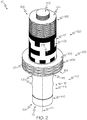
- Fig. 2 is a perspective view of a second exemplary hole location target according to the first example of the present description in an assembled state.
- Fig 3 is an exploded perspective view of the hole location target of Fig. 1 .
- Fig. 4A is cross-sectional view of the hole location target of Fig. 1 inserted into a hole of a workpiece W in a radially contracted state.
- Fig. 4B is cross-sectional view of the hole location target of Fig. 4A in a radially expanded state.
- the hole location target 10 includes a first end 101 configured to be inserted into a hole H of a workpiece W and a second end 102 opposite to the first end 101.
- the hole location target 10 includes a self-centering insert 110 and an optical target 120 attached to the self-centering insert 110.
- the self-centering insert 110 is positioned near the first end 101 and the optical target 120 is positioned near the second end 102 such that the self-centering insert 110 can be inserted into the hole H of the workpiece and the optical target 120 can remain outside of the hole H of the workpiece W.
- the self-centering insert 110 has a centerline 111 and the optical target 120 is at a fixed position relative to the centerline 111 of the self-centering insert 110.
- the self-centering insert 110 is configured to be inserted into the hole H of the workpiece W and to be self-centered such that the centerline 111 of the self-centering insert 110 is positioned coaxially with a respective centerline C of the hole H of the workpiece W.
- a method that measures a location of the centerline 111 of the self-centering insert 110 can be employed to determine a location of the centerline C of the hole H of the workpiece W.
- the optical target 120 can be at a fixed position relative to the centerline 111 of the self-centering insert 110, a method that measures a location of the optical target 120 can be employed to determine the location of the centerline 111 of the self-centering insert 110 and, thus, to determine the location of the centerline C of the hole H of the workpiece W.
- the optical target 120 has a cylindrical exterior surface 121 that is concentric to the centerline 111 of the self-centering insert 110.
- a method that measures a location of the cylindrical exterior surface 121 can be employed to determine the location of the centerline 111 of the self-centering insert 110 and, thus, to determine the location of the centerline C of the hole H of the workpiece W.
- the self-centering insert 110 of the first example includes a radially expandable bushing 112.
- the radially expandable bushing 112 can include any tubular structure capable of inserting into the hole H of the workpiece W and capable of radially expanding to self-center the centerline 111 of the self-centering insert 110 to the centerline C of the hole H of the workpiece W.
- the radially expandable bushing 112 takes the form of an expandable bellows 114.
- the radially expandable bushing 112 can take the form of an expandable collet such as is described below with respect to the third example.
- the expandable bellows 114 of the present description is a tubular structure in which an axial contraction of the expandable bellows 114 translates into a radial expansion of expandable bellows 114 and an axial expansion of the expandable bellows 114 translates into a radial contraction of expandable bellows 114.
- the expandable bellows 114 includes a first bellows end 115 and a second bellows end 116 and one or more radial ridges 118 between the first bellows end 115 and the second bellows end 116.
- the expandable bellows 114 by axially expanding the expandable bellows 114, the one or more radial ridges 118 contract radially, thereby permitting the expandable bellows 114 to be inserted into a hole H of a workpiece W.
- the expandable bellows 114 after inserting the expandable bellows into the hole H of the workpiece W, the expandable bellows 114 can be axially contracted to radially expand one or more radial ridges 118.
- the one or more radial ridges 118 then contact the walls defining the hole H of the workpiece W, thus causing a self-centering of the centerline 111 of the expandable bellows 114 to the respective centerline C of the hole H of the workpiece W.
- the optical target 120 is attached to the self-centering insert 110 such that the cylindrical exterior surface 121 is concentric to the centerline 111 of the self-centering insert 110.
- the optical target 120 can be fixedly positioned to the self-centering insert 110 such that a position of the optical target is fixed with respect to a position of centerline 111 of the self-centering insert 110.
- the positioning of the optical target 120 with respect to the position of centerline 111 of the self-centering insert 110 can be permanent.
- the self-centering insert 110 and the optical target 120 can be combined as a monolithic body.
- the self-centering insert 110 and the optical target 120 can be unitary formed together as a monolithic body by one or more processes, such as casting, molding, and additive manufacturing.
- the cylindrical exterior surface 121 of the optical target 120 has a surface cylindricity of 5 ⁇ m or less (or a tolerance of concentricity of the cylindrical surface to the centerline that is within 5 ⁇ m for improved precision of determining the centerline C of the hole H of the workpiece W.
- the self-centering insert 110 includes a bore 117 for accommodating a compression device 130.
- the compression device 130 is configured to axially contract the expandable bellows 114.
- the compression device 130 includes a bolt 140 and a nut 160.
- the bolt 140 has a first bolt end 141 and a second bolt end 142.
- the bolt 140 includes a bolt shaft 143 positioned at the first bolt end 141 of the bolt 140 and a bolt head 144 positioned at the second bolt end 142 of the bolt 140.
- the bolt shaft 143 includes a first shaft end 145 and a second shaft end 146. Exterior threads 147 are positioned at the first shaft end 145 of the bolt shaft 143, and the bolt head 144 is joined to the second shaft end 146.
- the bolt head 144 includes a first bolt head end 148 and a second bolt head end 149.
- a first bolt face 151 is positioned at the first bolt head end 148
- a second bolt face 152 is positioned at the second bolt head end 149
- an outer bolt head surface 150 is positioned between the first bolt head end 148 and the second bolt head end 149.
- the outer bolt head surface 150 can take the form of a plurality of faces extending around a circumference of the bolt head 144 to improve retention of the bolt 140 within the bore 117 of the self-centering insert 110.
- the nut 160 has a first nut end 161 and a second nut end 162.
- a first nut face 163 is positioned at the first nut end 161
- a second nut face 164 is positioned at the second nut end 162
- an outer nut surface 165 is positioned between the first nut end 161 and the second nut end 162.
- the outer nut surface 165 can include a nut gripping surface 166 configured to improve a grip of the nut 160.
- the nut gripping surface 166 can take the form of a knurled surface for manually torqueing of the nut 160.
- the nut gripping surface 166 can take other forms, such as a plurality of faces for torqueing the nut 160 with a tool.
- the nut bore 167 passes through the nut 160 from the first nut face 163 to the second nut face 164, and the nut bore 167 includes interior threads 168 configured to engage with the exterior threads 147 of the bolt 140.
- the bolt shaft 143 passes through bore 117 at a bellows end surface 119 at the first end 101 of the self-centering insert 110 to target end surface 124 at the second end 102 of the optical target 120, and the exterior threads 147 of the bolt 140 engage with the interior threads 168 of the nut 160.
- the first nut face 163 engages with the optical target 120, and the first bolt face 151 engages with the first bellows end 115 of the expandable bellows 114.
- the bolt 140 and nut 160 form a compression device 130 configured to contract the expandable bellows 114 by turning the nut 160.
- the compression device 130 is not limited to the above-described example. In other examples, the position of the bolt 140 and nut 160 can be reversed. In yet other examples, the compression device 130 may take the form of a rachet or any other compression device configured to axially contract the expandable bellows 114.
- the hole location target 10 includes a collar 103.
- the collar 103 includes a first collar end surface 104, a second collar end surface 105, and an outer collar surface 106 positioned between the first collar end surface 104 and a second collar end surface 105.
- the outer collar surface 106 can include a collar gripping surface 107 configured to improve a grip of the collar 103.
- the collar gripping surface 107 can take the form of a knurled surface for manually torqueing of the collar 103.
- the collar gripping surface 107 can take other forms, such as a plurality of faces for torqueing the collar 103 with a tool.
- the optical target 120 includes a two-dimensional pattern thereon 122.
- the two-dimensional pattern thereon 122 can be a plurality of a pattern of dots 123 disposed around the cylindrical exterior surface 121 of the optical target 120.
- the pattern of dots 123 can be unique such that the pattern of dots 123 on an optical target 120 of a hole location target 10 is different from the pattern of dots 123 on an optical target 120 of another hole location target 10.
- the two-dimensional pattern thereon 122 can be a plurality of a two-dimensional barcodes 125 disposed around the cylindrical exterior surface 121 of the optical target 120.
- the two-dimensional barcode 125 can be unique such that the two-dimensional barcode 125 on an optical target 120 of a hole location target 10 is different from the two-dimensional barcode 125 on an optical target 120 of another hole location target 10.
- the two-dimensional pattern 122 can have a predetermined calibration with respect to the centerline 111 of the self-centering insert 110, such as a predetermined six degree of freedom calibration with respect to the centerline 111 of the self-centering insert 110.
- the predetermined calibration of the two-dimensional pattern 122 can be used to precisely determine the centerline 111 of the self-centering insert 110 based on a determined position of the two-dimensional pattern 122.
- the two-dimensional pattern 122 includes a retroreflective material.
- images of the two-dimensional pattern 122 may be captured by emitting light to the retroreflective material of the two-dimensional pattern 122 on the cylindrical exterior surface 121 of the optical target 120 and capturing light reflected by the retroreflective material.
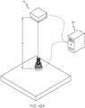
- Fig. 5 is a representation of an exemplary hole location measurement system according to the first example of the present description.
- the hole location measurement system 100 of the first example of the present description includes the hole location target 10 as described above, a camera system 40, and a computer system 50 in communication with the camera system 40.
- the camera system 40 is configured to capture images of the two-dimensional pattern 122 on the optical target 120.
- the computer system 50 is configured to measure three-dimensional locations of features of the two-dimensional pattern 122 on the optical target 120 and to extract a location of a cylinder axis of the cylinder surface geometry.
- the computer system is configured to measure three-dimensional locations of features of the two-dimensional pattern on a cylindrical exterior surface of the optical target, to fit the three-dimensional locations of the features of the two-dimensional pattern to a cylinder surface geometry, and to extract a location of a cylinder axis of the cylinder surface geometry.
- the computer system 50 may be separate from or integrated with the camera system 40.
- hole location measurement system 100 includes a plurality of the hole location targets 10.
- the camera system 40 is configured to capture images of the two-dimensional patterns 122 of the plurality of the hole location targets 10.
- a single image captured by the camera system 40 includes the two-dimensional patterns 122 of the plurality of the hole location targets 10.
- the camera system 40 is a three-dimensional optical scanner. In other examples, the camera system is a portable three-dimensional optical scanner. Alternatively, the three-dimensional optical scanner may be of a type supported on an articulating arm.
- the portable three-dimensional optical scanner is shown as a stereo camera-styled scanner, having a pair of spaced lenses configured to acquire real-time data from a plurality of poses, utilizing a grid style coordinate system to generate and transfer 3-D images.
- the portable three-dimensional optical scanner includes an inertial navigation system.
- the inertial navigation system contained within the portable three-dimensional optical scanner provides a fixed point of reference, relative to an X-Y-Z set of common coordinates on which each scanned pose is based, irrespective of operator positioning of the physical scanner device.
- the angle and timing of each pose i.e. orientation of the scanner in space and time relative to the target, is assured via the inertial navigation system to have a common frame of reference.
- Fig. 6 is a flow diagram of an exemplary method for measuring a location of a hole H of a workpiece W according to the first example of the present description.
- the method 1000 includes, at block 1002, centering an insert within a hole H having a centerline C.
- the insert can be the self-centered insert 110 or can be a different insert that is centered by any external means.
- An optical target 120 is attached to the insert at a fixed position relative to the centerline 111 of the self-centering insert 110.
- the optical target 120 includes a two-dimensional pattern 122 thereon.
- the method 1000 further includes, at block 1004, capturing images of the two-dimensional pattern 122 on the optical target 120.
- the images can be captured by the camera system 40 as described above.
- the step of capturing images, at block, 1004, includes emitting light to a retroreflective material of the two-dimensional pattern 122 on the optical target 120 and capturing light reflected by the retroreflective material.
- the method 1000 further includes, at block 1006, measuring three-dimensional locations of features of the two-dimensional pattern 122 on the optical target 120, at block 1008, extracting a location of the centerline 111 of the self-centering insert 110 based on the three-dimensional locations of features of the two-dimensional pattern 122 and the fixed position of the optical target 120 relative to the centerline 111 of the self-centering insert 110.
- Each of these steps can be performed by the camera system 40, the computer system 50, or the camera system 40 integrated with the computer system 50.
- the step 1006 of measuring three-dimensional locations of features of the two-dimensional pattern 122 on the optical target 120 is performed by analysis of the of the images captured by the camera system 40 to identify the two dimensional pattern of the optical target within the acquired image and to determine distance relative to the optical target based on a measure of target features within the image.
- measuring three-dimensional locations of features of the two-dimensional pattern 122 on the optical target 120 includes measuring three-dimensional locations of dot centroids of a pattern of dots 123 of the two-dimensional pattern 122 shown in Fig. 1 .
- Each dot of the pattern of dots 123 has a centroid which can be determined from the images captured by the camera system 40, and each centroid has a specific three-dimensional location.
- a plurality of precise three-dimensional locations on the optical target 120 can be found.
- measuring three-dimensional locations of features of the two-dimensional pattern 122 on the optical target 120 includes measuring three-dimensional locations of intersections of a two-dimensional barcode 125 of the two-dimensional pattern 122 shown in Fig. 2 .
- Each line of the two-dimensional barcode 125 defines a one-dimensional vector in three-dimensional space, which can be determined from the images captured by the camera system 40, and the intersection of two lines of the two-dimensional barcode 125 defines a specific three-dimensional location.
- the step 1008 of fitting the three-dimensional locations of the features of the two-dimensional pattern 122 to a cylinder surface geometry can be performed by, for example, calculating a best fit of the three-dimensional locations of the features to a cylinder surface geometry.
- the plurality of precise three-dimensional locations on the optical target 120 can be used to accurately find a cylinder surface geometry of the optical target 120.
- the step 1010 of extracting a location of a cylinder axis of the cylinder surface geometry can be performed by, for example, calculating a best fit of a cylinder axis to the cylinder surface geometry.
- the extracted cylinder location of the cylinder axis can be precisely equated to a centerline of the hole H of the workpiece W.
- the method 1000 further includes comparing the three-dimensional locations of features of the two-dimensional pattern 122 on the optical target 120 to a database of three-dimensional locations of features of known optical targets. As shown in Fig. 5 , the two-dimensional pattern 122 on the optical target 120 can be unique. Thus, the method 1000 can correlate a unique optical target 120 to a unique location of the hole H of the workpiece W.
- Fig. 7 is a perspective view of a first exemplary hole location target according to a second example of the present description in an assembled state.
- Fig. 8 is a perspective view of a second exemplary hole location target according to the second example of the present description in an assembled state.
- Fig. 9 is an exploded perspective view of the hole location target of Fig. 7 .
- Fig. 10A is cross-sectional view of the hole location target of Fig. 7 inserted into a hole of a workpiece W in a radially contracted state.
- Fig. 10B is cross-sectional view of the hole location target of Fig. 10A in a radially expanded state.
- the hole location target 20 includes a first end 201 configured to be inserted into a hole H of a workpiece W and a second end 202 opposite to the first end 201.
- the hole location target 20 includes a self-centering insert 210 and an optical target 220 attached to the self-centering insert 210.
- the self-centering insert 210 is positioned near the first end 201 and the optical target 220 is positioned near the second end 202 such that the self-centering insert 210 can be inserted into the hole H of the workpiece and the optical target 220 can remain outside of the hole H of the workpiece W.
- the self-centering insert 210 has a centerline 211 and the optical target 220 is attached to the self-centering insert 210 at a fixed position relative to the centerline 211 of the self-centering insert 210, and the optical target 220 includes a light-emitting display 270.
- the optical target 220 including the light-emitting display 270
- a method that measures a location of the light-emitting display 270 can be employed to determine a location of the centerline 211 of the self-centering insert 210, which can be correlated to the location of the centerline C of the hole H of the workpiece W.
- the self-centering insert 210 is configured to be inserted into the hole H of the workpiece W and to be self-centered such that the centerline 211 of the self-centering insert 210 is positioned coaxially with a respective centerline C of the hole H of the workpiece W.
- a method that measures a location of the centerline 211 of the self-centering insert 210 can be employed to determine a location of the centerline C of the hole H of the workpiece W.
- the self-centering insert 210 can include a bore 217 for accommodating a compression device 230.
- the self-centering insert 210 of the first example includes a radially expandable bushing 212.
- the radially expandable bushing 212 can include any tubular structure capable of inserting into the hole H of the workpiece W and capable of radially expanding to self-center the centerline 211 of the self-centering insert 210 to the centerline C of the hole H of the workpiece W.
- the radially expandable bushing 212 takes the form of an expandable bellows 214.
- the radially expandable bushing 212 can take the form of an expandable collet such as is illustrated with respect to the third example below.
- the expandable bellows 214 of the present description is a tubular structure in which an axial contraction of the expandable bellows 214 translates into a radial expansion of expandable bellows 214 and an axial expansion of the expandable bellows 214 translates into a radial contraction of expandable bellows 214.
- the expandable bellows 214 includes a first bellows end 215 and a second bellows end 216 and one or more radial ridges 218 between the first bellows end 215 and the second bellows end 216.
- the expandable bellows 214 by axially expanding the expandable bellows 214, the one or more radial ridges 218 contract radially, thereby permitting the expandable bellows 214 to be inserted into a hole H of a workpiece W.
- the expandable bellows 214 after inserting the expandable bellows 214 into the hole H of the workpiece W, the expandable bellows 214 can be axially contracted to radially expand one or more radial ridges 218.
- the one or more radial ridges 218 then contact the walls defining the hole H of the workpiece W, thus causing a self-centering of the centerline 211 of the expandable bellows 214 to the respective centerline C of the hole H of the workpiece W.
- the optical target 220 is attached to the self-centering insert 110 such that the optical target 220 is at a fixed position relative to the centerline 211 of the self-centering insert 210.
- the fixed positioning of the optical target 220 with respect to the position of centerline 211 of the self-centering insert 210 can be permanent.
- the self-centering insert 210 and a target support 203 for supporting the optical target 220 can be combined as a monolithic body.
- the self-centering insert 210 and the target support 203 can be unitary formed together as a monolithic body by one or more processes, such as casting, molding, and additive manufacturing.
- the self-centering insert 210 includes a compression device 230 configured to axially contract the expandable bellows 214.
- the compression device 230 includes a bolt 240 and a nut 260.
- the bolt 240 has a first bolt end 241 and a second bolt end 242.
- the bolt 240 includes a bolt shaft 243 positioned at the first bolt end 241 of the bolt 240 and a bolt head 244 positioned at the second bolt end 242 of the bolt 240.
- the bolt shaft 243 includes a first shaft end 245 and a second shaft end 246. Exterior threads 247 are positioned at the first shaft end 245 of the bolt shaft 243, and the bolt head 244 is joined to the second shaft end 246.
- the bolt head 244 includes a first bolt head end 248 and a second bolt head end 249.
- a first bolt face 251 is positioned at the first bolt head end 248, a second bolt face 252 is positioned at the second bolt head end 249, and an outer bolt head surface 250 is positioned between the first bolt head end 248 and the second bolt head end 249.
- the outer bolt head surface 250 can take the form of a plurality of faces extending around a circumference of the bolt head 244 to improve torqueing of the bolt 240.
- the nut 260 has a first nut end 261 and a second nut end 262.
- a first nut face 263 is positioned at the first nut end 261, a second nut face 264 is positioned at the second nut end 262, and an outer nut surface 265 is positioned between the first nut end 261 and the second nut end 262.
- the nut gripping surface 266 can take the form of a plurality of faces for improve retention with the self-centering insert 210.
- the nut bore 267 passes through the nut 260 from the first nut face 263 to the second nut face 264, and the nut bore 267 includes interior threads 268 configured to engage with the exterior threads 247 of the bolt 240.
- the bolt shaft 243 passes through bore 217 at the first bellows end 215 through the expandable bellows 214 to the second bellows end 216, and the exterior threads 247 of the bolt 240 engage with the interior threads 268 of the nut 260.
- the bolt 240 engages with the first bellows end 215 and the nut 260 engages with the second bellows end 216.
- the bolt 240 and nut 260 form a compression device 230 configured to contract the expandable bellows 214 by turning the bolt 240.
- the compression device 230 is not limited to the above-described example. In other examples, the position of the bolt 240 and nut 260 may be reversed. In yet other examples, the compression device 230 may take the form of a rachet or any other compression device configured to axially contract the expandable bellows 214.
- the optical target 220 includes a light-emitting display 270.
- the light-emitting display 270 includes, for example, a liquid crystal display (LCD), a light emitted diode (LED), an organic light-emitting diode (OLED), or a quantum dot light emitting diodes (QLED).
- the light-emitting display 270 includes a two-dimensional pattern 222 thereon. By measuring a location of the light-emitting display 270, a location of the centerline 211 of the self-centering insert 210 can be determined, which can be correlated to the location of the centerline C of the hole H of the workpiece W.
- the two-dimensional pattern 22 can have a predetermined calibration with respect to the centerline 211 of the self-centering insert 210, such as a predetermined six degree of freedom calibration with respect to the centerline 211 of the self-centering insert 210.
- the predetermined calibration of the two-dimensional pattern 222 can be used to precisely determine the centerline 211 of the self-centering insert 210 based on a determined position of the two-dimensional pattern 222. Furthermore, by way emitting light from the light-emitting display 270, the two-dimensional pattern 222 thereon can be more easily captured by a camera system.
- the two-dimensional pattern 222 thereon can a plurality of a pattern of dots 223.
- the pattern of dots 223 can be displayed to be unique such that the pattern of dots 223 on an optical target 220 of a hole location target 20 is different from the pattern of dots 223 displayed on an optical target 220 of another hole location target 20.
- the three-dimensional locations of dot centroids of the pattern of dots 223 of the two-dimensional pattern 222 can be determined.
- Each dot of the pattern of dots 223 has a centroid which can be determined from the images captured by a camera system, and each centroid has a specific three-dimensional location.
- a plurality of precise three-dimensional locations of the light-emitting display 270 of the optical target 220 can be found.
- the two-dimensional pattern 222 thereon can a plurality of a two-dimensional barcode 225 displayed by the optical target 220.
- the two-dimensional barcode 225 can be displayed to be unique such that the two-dimensional barcode 225 on an optical target 220 of a hole location target 20 is different from the two-dimensional barcode 225 displayed on an optical target 220 of another hole location target 20.
- Each line of the barcode pattern defines a one-dimensional vector in three-dimensional space, which can be determined from the images captured by a camera system, and the intersection of two lines of the barcode pattern defines a specific three-dimensional location.
- a plurality of precise three-dimensional locations on the light-emitting display 270 of the optical target 220 can be found.
- the optical target 220 can preferably modify the two-dimensional pattern 222 of the optical target 220.
- Modifying the two-dimensional pattern 222 can include, for example, changing a size of the two-dimensional pattern, modifying an intensity of light of the light-emitting display 270, modifying a wavelength of light of the light-emitting display 270, and temporal modulation of light of the light-emitting display 270.
- Fig. 11 is a representation of an exemplary hole location measurement system according to the second example of the present description.
- the hole location measurement system 200 includes the hole location target 20, a camera system 40 configured to capture images of the two-dimensional pattern 222 of the optical target 220, and a computer system 50 in communication with the camera system 40 and in communication with hole location target 20.
- the computer system 50 is configured to control modification of the two-dimensional pattern 222 of the optical target 220 and to determine three-dimensional coordinates of the centerline 211 of the self-centering insert from the images of the two-dimensional pattern 222 of the optical target 220.
- the computer system 50 may be separate from or integrated with the camera system 40.
- hole location measurement system 200 includes a plurality of the hole location targets 20.
- the camera system 40 is configured to capture images of the two-dimensional patterns 222 of the plurality of the hole location targets 20.
- a single image captured by the camera system 40 includes the two-dimensional patterns 222 of the plurality of the hole location targets 20.
- the camera system 40 is a three-dimensional optical scanner. In other examples, the camera system is a portable three-dimensional optical scanner. Alternatively, the three-dimensional optical scanner may be of a type supported on an articulating arm.
- the portable three-dimensional optical scanner is shown as a stereo camera-styled scanner, having a pair of spaced lenses configured to acquire real-time data from a plurality of poses, utilizing a grid style coordinate system to generate and transfer 3-D images.
- the portable three-dimensional optical scanner can include an inertial navigation system.
- the inertial navigation system contained within the portable three-dimensional optical scanner provides a fixed point of reference, relative to an X-Y-Z set of common coordinates on which each scanned pose is based, irrespective of operator positioning of the physical scanner device.
- the angle and timing of each pose i.e. orientation of the scanner in space and time relative to the target, is assured via the inertial navigation system to have a common frame of reference.
- the light-emitting display 270 and the camera system 40 can include at least one of matching polarized filters and matching wavelength filters.
- a capability of a hole location measurement system 200 to capture images of the two-dimensional patterns 222 of the plurality of the hole location targets 20 can be enhanced.
- Fig. 12 is a flow diagram of an exemplary method for measuring a location of a hole H of a workpiece W according to the second example of the present description.
- the method 2000 for measuring a location of a hole H includes, at block 2002, centering an insert within a hole having a centerline.
- the insert can be the self-centered insert 210 or can be a different insert that is centered by any external means.
- the optical target 220 is attached to the insert at a fixed position relative to the centerline 211 of the insert.
- the optical target 220 includes the light-emitting display 270 comprising a two-dimensional pattern 222 thereon.
- the two-dimensional pattern 222 can include, for example, the pattern of dots 223 or the two-dimensional barcode 225.
- the method 2000 further includes, at block 2004, capturing images of the two-dimensional pattern 222 of the optical target.
- the images can be captured by the camera system 40 as described above.
- the method 2000 further includes, at block 2006, modifying the two-dimensional pattern 222 of the optical target 220.
- the method 2000 further includes, at block 2008, capturing images of the modified two-dimensional pattern 222 of the optical target 220.
- the images can be captured by the camera system 40 as described above.
- modifying the two-dimensional pattern 222 can include, for example, changing a size of the two-dimensional pattern, modifying an intensity of light of the light-emitting display 270, modifying a wavelength of light of the light-emitting display 270, and temporal modulation of light of the light-emitting display 270.
- Changing a size of the two-dimensional pattern 222 can include, for example, increasing or decreasing size of each dot of the pattern of dots 223 or increasing or decreasing a size of a bar of the two-dimensional barcode 225.
- the method 2000 can compensate for a distance between the camera system 40 and the hole location target 20.
- the camera system 40 alone or by way of the computer system 50, can control a size of the two-dimensional pattern 222.
- the method 2000 can provide for an interactive control of the size of the two-dimensional pattern 222 based on real-time feedback from the camera system 40 capturing the images of the two-dimensional pattern 222.
- the method 2000 can compensate for environmental conditions, e.g. intensity of background light.
- the camera system 40 alone or by way of the computer system 50, can control an intensity of light of the two-dimensional pattern 222.
- the method 2000 can provide for an interactive control of the intensity of the two-dimensional pattern 222 based on real-time feedback from the camera system 40 capturing the images of the two-dimensional pattern 222.
- the method 2000 can compensate for environmental conditions by distinguishing the wavelength of light emitted from the light-emitting display 270.
- the camera system 40 alone or by way of the computer system 50, can control a wavelength of light of the two-dimensional pattern 222.
- the method 2000 can provide for an interactive control of the wavelength of the two-dimensional pattern 222 based on real-time feedback from the camera system 40 capturing the images of the two-dimensional pattern 222.
- the method 2000 can compensate for environmental conditions.
- Temporal modulation of light can include, for example, a blinking of light of the light-emitting display 270.
- the camera system 40 alone or by way of the computer system 50, can control temporal modulation of light of the two-dimensional pattern 222.
- the method 2000 can provide for an interactive control of the phase of the two-dimensional pattern 222 based on real-time feedback from the camera system 40 capturing the images of the two-dimensional pattern 222.
- modifying the two-dimensional pattern 222 of the optical target 220 by the camera system 40, alone or by way of the computer system 50, can provide for method 2000 that adjusts the optical target 220 to the conditions at the time of taking the measurements.
- modifying the two-dimensional pattern 222 of the optical target 220 can communicate a status of the hole location target 20.
- modifying the two-dimensional pattern 222 can communicate a signal with a status of the hole location target 20, which can include correlating the signal with an identity of the hole location target.
- Fig. 13 is a perspective view of an exemplary hole location target according to a third example of the present description in an assembled state.
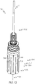
- Fig. 14 is an exploded perspective view of the hole location target of Fig. 13 .
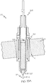
- Fig. 15A is cross-sectional view of the hole location target of Fig. 13 inserted into a hole of a workpiece W in a radially contracted state.
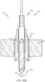
- Fig. 15B is cross-sectional view of the hole location target of Fig. 15A in a radially expanded state.
- the hole location target 30 includes a first end 301 configured to be inserted into a hole H of a workpiece W and a second end 302 opposite to the first end 301.
- the hole location target 30 includes a self-centering insert 310 and a laser beam emitter 320 attached to the self-centering insert 310.
- the self-centering insert 310 is positioned near the first end 301 and the laser beam L is emitted near the second end 302 such that the self-centering insert 310 can be inserted into the hole H of the workpiece and the laser beam L can be emitted outside of the hole H of the workpiece W.
- the self-centering insert 310 has a centerline 311 and the axis of the emitted laser beam L is concentric to the centerline 311 of the self-centering insert 310.
- the self-centering insert 310 is configured to be inserted into the hole H of the workpiece W and to be self-centered such that the centerline 311 of the self-centering insert 310 is positioned coaxially with a respective centerline C of the hole H of the workpiece W.
- a method that measures a location of the centerline 311 of the self-centering insert 310 can be employed to determine a location of the centerline C of the hole H of the workpiece W.
- the axis of the emitted laser beam L can be concentric to the centerline 311 of the self-centering insert 310, a method that measures the location of the emitted laser beam L can be employed to determine the location of the centerline 311 of the self-centering insert 310 and, thus, to determine the location of the centerline C of the hole H of the workpiece W.
- the axis of the emitted laser beam is concentric to the centerline of the self-centering insert to 5 ⁇ m or less.
- the self-centering insert 310 of the first example includes a radially expandable bushing 312.
- the radially expandable bushing 312 can include any tubular structure capable of inserting into the hole H of the workpiece W and capable of radially expanding to self-center the centerline 311 of the self-centering insert 310 to the centerline C of the hole H of the workpiece W.
- the radially expandable bushing 312 takes the form of an expandable collet 314.
- the radially expandable bushing 312 can take the form of an expandable bellows such as is illustrated with respect to the first and third examples above.
- the expandable collet 314 of the present description is a tubular structure in which radially outward force applied to the expandable collet 314 radially expands the expandable collet 314.
- the expandable collet 314 includes a first collet end 315 and a second collet end 316 and axial beams 318 between the first collet end 315 and the second collet end 316.
- the axial beams 318 circumferentially separate and expand radially outward.
- the axial beams 318 contract radially, thereby permitting the expandable collet 314 to be inserted into a hole H of a workpiece W.
- the radially outward force is applied to the expandable collet 314 and the axial beams 318 radially expand.
- the axial beams 318 then contact the walls defining the hole H of the workpiece W, thus causing a self-centering of the centerline 311 of the expandable collet 314 to the respective centerline C of the hole H of the workpiece W.
- the laser beam emitter 320 is attached to the self-centering insert 310 such that the emitted laser beam L is concentric to the centerline 311 of the self-centering insert 310.
- the laser beam emitter 320 can be fixedly positioned to the self-centering insert 310 such that a position of the laser beam emitter 320 is fixed with respect to a position of centerline 311 of the self-centering insert 310.
- the positioning of the laser beam emitter 320 with respect to the position of centerline 311 of the self-centering insert 310 can be permanent.
- the self-centering insert 310 includes an expansion device 330 configured to apply a force to radially expand the expandable collet 314.
- the expansion device 330 includes a first wedge 340, a second wedge 350, and a collar 360.
- the first wedge 340 has a first wedge lower end 341, a first wedge upper end 342 opposite to the first wedge lower end 341, and a first hollow shaft 343 between the first wedge lower end 341 and the first wedge upper end 342.
- a first inclined wedge surface 344 is positioned at the first wedge lower end 341 of the first wedge 340.
- the first inclined wedge surface 344 is configured to engage with an inclined collet surface of the expandable collet 314.
- Exterior threads 345 are positioned on an exterior surface of the first hollow shaft 343, and a wedge grip 346 is positioned at the first wedge upper end 342 of the first wedge 340.
- the wedge grip 346 can include a wedge gripping surface 348.
- the wedge gripping surface 348 can take the form of a knurled surface for improved manually torqueing of the wedge grip 346. Alternatively, the wedge gripping surface 348 can take other forms, such as a plurality of faces for torqueing the wedge grip 346 with a tool.
- the first wedge 340 is sized to pass through an first end of a hollow interior of the expandable collet 314 such that the first inclined wedge surface 344 engages with the inclined collet surface 319 and such that the exterior threads 345 and wedge grip 346 extend past a second end of the hollow interior of the expandable collet 314.
- the second wedge 350 has a second wedge lower end 351, a second wedge upper end 352 opposite to the second wedge lower end 351, and a second hollow shaft 353 between the second wedge lower end 351 and the second wedge upper end 352.
- a second inclined wedge surface 354 is positioned at the second wedge upper end 352 of the second wedge 350.
- the second inclined wedge surface 354 is configured to engage with an inclined collet surface 319 of the expandable collet 314.
- the second hollow shaft 353 is sized to pass through the hollow interior of the expandable collet 314 such that the second inclined wedge surface 354 engages with the inclined collet surface 319.
- the collar 360 can provide axial movement of the first wedge 340 towards the second wedge 350. As shown, the collar 360 includes a first collar portion 361 and a second collar portion 366.
- the first collar portion 361 has a first collar lower end 362 and a first collar upper end 363.
- the first collar upper end 363 can include a wavy upper surface 364 configured to engage with a corresponding wavy surface of the second collar portion, and a first collar bore 365 passes through the first collar portion 361 from the first collar lower end 362 to the first collar upper end 363.
- the second collar portion 366 has a second collar lower end 367 and a second collar upper end 368.
- the second collar portion 366 can include a second collar gripping surface 369.
- the second collar gripping surface 369 can take the form of a knurled surface for improved manually torqueing of the second collar gripping surface 369.
- the second collar gripping surface 369 can take other forms, such as a plurality of faces for torqueing the second collar gripping surface 369 with a tool.
- the second collar portion 366 includes interior threads 370 in a bore passing through the second collar portion 366 from the second collar lower end 367 to the second collar upper end 368.
- the interior threads 370 of the second collar portion 366 are configured to engage with the exterior threads of the first wedge 340 to axially move the first wedge 340 towards the second wedge 350.
- the first wedge 340, the second wedge 350, and the collar 360 form an expansion device 330 configured to apply a radially outward force to the expandable collet 314 by turning the collar 360.
- the expansion device 330 is not limited to the above-described example. In other examples, the position of the first wedge 340, the second wedge 350, and the collar 360 can be reversed. In yet other examples, the expansion device 330 may take the form of a spring or any other expansion device configured to radially expand the expandable collet 314.
- the hole location target 30 further includes a power device 380.
- the power device 380 includes a battery 381, a power switch 382, and a conduit 383.
- the power device 380 is not limited to the above-described example. In other examples, the power device 380 could include a wire connected to an electricity supply.
- Fig. 16A is a representation of an exemplary hole location measurement system according to the third example of the present description, including an optical sensor at a first distance d1 from the laser beam emitter.
- Fig. 16B is a representation of the exemplary hole location measurement system according to the third example of the present description, including the optical sensor at a second distance d2 from the laser beam emitter.
- the hole location measurement system 300 includes the hole location target 30, in which the axis of the emitted laser beam L is concentric to the centerline 311 of the self-centering insert 310, an optical system 41 sensing the location of the emitted laser beam L at multiple distances from the laser beam emitter 320, and a computer system 50 in communication with the hole location target 30 and optionally the optical system 41.
- the computer system 50 is configured to determine three-dimensional coordinates of the centerline 311 of the self-centering insert 310 from the sensed locations of the emitted laser beam L.
- the optical system 41 includes any optical system capable of sensing the location of the emitted laser beam L at multiple distances from the laser beam emitter 320.
- the computer system 50 may be separate from or integrated with the camera system 40.
- hole location measurement system 300 includes a plurality of the hole location targets 30.
- the optical system 41 is configured to sense the location of multiple emitted laser beams L at the same time. Thus, by sensing the location of multiple emitted laser beams L at the same time, the hole location measurement system 300 enables for measurements of multiple holes at the same time.
- the optical system 41 can be a portable optical system.
- the optical system 41 is of a type supported on an articulating arm.
- the laser beam emitter 320 is configured to modulate a power of the emitted laser beam L. By controlling modulation of the emitted laser beam L, laser beam emitter 320 can compensate for environmental conditions, e.g. intensity of background light.
- the optical system 41 and/or the computer system 50 is configured to control the modulation of the emitted laser beam L.
- the hole location measurement system 300 can compensate for environmental conditions, e.g. intensity of background light, by modulating the emitted laser beam L to facilitate sensing of the emitted laser beam L by the optical system 41.
- the hole location measurement system 300 can provide for an interactive control of the modulation of the emitted laser beam L based on real-time feedback from the optical system 41 sensing the location of emitted laser beam L.
- the emitted laser beam L is modulated to send a signal
- the computer system 50 is configured to extract a signal from the modulated powder of the emitted laser beam L.
- the signal can be indicative of a status of the hole location target, an identity of the hole location target, or a status of the laser beam emitter.
- the laser beam emitter 320 and the optical system 41 can include at least one of matching polarized filters and matching wavelength filters.
- a capability of a hole location measurement system 300 to sense the location of the emitted laser beam L can be enhanced.
- Fig. 17 is a flow diagram of an exemplary method for measuring a location of a hole of a workpiece W according to the third example of the present description.
- the method 3000 for measuring a location of a hole H includes, at block 3002, centering an insert within a hole having a centerline.
- the insert can be the self-centered insert 310 or can be a different insert that is centered by any external means.
- the method 3000 further includes, at block 3004, emitting a laser beam from a laser beam emitter attached to the insert, wherein the axis of the emitted laser beam is concentric to the centerline of the insert.
- the method 3000 further includes, at block 3006, sensing the location of the emitted laser beam at multiple distances from the laser beam emitter.
- the method 3000 further includes, at block 3008, determining three-dimensional coordinates of the centerline of the self-centering insert from the sensed locations of the emitted laser beam.
- the method 3000 further includes modulating a power of the emitted laser beam and extracting a signal from the modulated powder of the emitted laser beam. In other examples, the method 3000 further includes correlating the signal with a status of the hole location target.
- the method 3000 further includes correlating the signal with an identity of the hole location target.
- the method 3000 further includes correlating the signal with a status of the laser beam emitter.
- the method 3000 further includes rotating an article having the hole therein, emitting the laser beam from the laser beam emitter during the rotating, sensing the location of the emitted laser beam at multiple distances from the laser beam emitter during the rotating, and determining three-dimensional coordinates of the centerline of the self-centering insert throughout the rotation from sensed locations of the emitted laser beam.
- Examples of the present disclosure may be described in the context of an aircraft manufacturing and service method 4000, as shown in Fig. 18 , and an aircraft 4002, as shown in Fig. 19 .
- the aircraft manufacturing and service method 4000 may include specification and design 4004 of the aircraft 4002 and material procurement 4006.
- component/subassembly manufacturing 4008 and system integration 4010 of the aircraft 4002 takes place.
- the aircraft 4002 may go through certification and delivery 4012 in order to be placed in service 4014.
- routine maintenance and service 4016 which may also include modification, reconfiguration, refurbishment and the like.
- a system integrator may include without limitation any number of aircraft manufacturers and major-system subcontractors; a third party may include without limitation any number of venders, subcontractors, and suppliers; and an operator may be an airline, leasing company, military entity, service organization, and so on.
- the hole location targets, hole location measurement systems, and methods for measuring a location of a hole of the present disclosure may be employed during any one or more of the stages of the aircraft manufacturing and service method 1000, including specification and design 4004 of the aircraft 4002, material procurement 4006, component/subassembly manufacturing 4008, system integration 4010, certification and delivery 4012, placing the aircraft in service 4014, and routine maintenance and service 4016.
- the aircraft 4002 produced by example method 4000 may include an airframe 4018 with a plurality of systems 4020 and an interior 4022.
- the plurality of systems 4020 may include one or more of a propulsion system 4024, an electrical system 4026, a hydraulic system 4028, and an environmental system 4030. Any number of other systems may be included.
- the hole location targets, hole location measurement systems, and methods for measuring a location of a hole of the present disclosure may be employed for any of the systems of the aircraft 4002.
Landscapes
- Physics & Mathematics (AREA)
- Engineering & Computer Science (AREA)
- General Physics & Mathematics (AREA)
- Computer Vision & Pattern Recognition (AREA)
- Theoretical Computer Science (AREA)
- Electromagnetism (AREA)
- General Health & Medical Sciences (AREA)
- Artificial Intelligence (AREA)
- Toxicology (AREA)
- Health & Medical Sciences (AREA)
- Quality & Reliability (AREA)
- Radar, Positioning & Navigation (AREA)
- Remote Sensing (AREA)
- Length Measuring Devices By Optical Means (AREA)
Abstract
Description
- The present application relates to the field of hole location targets, hole location measurement systems, and methods for measuring a location of a hole.
- Touch-based coordinate measurement machines typically use a stylus to sweep an inside surface of a hole of a workpiece to determine a centerline of the hole, which takes significant time. Also, articles having holes to be measured by this technique are typically specifically designed to permit for insertion of and sweeping by a stylus of a touch-based coordinate measurement machine, thus restricting freedom of design.
- Accordingly, those skilled in the art continue with research and development in the field of hole location targets, hole location measurement systems, and methods for measuring a location of a hole.
- According to a first example, a hole location target includes a self-centering insert having a centerline and an optical target attached to the self-centering insert at a fixed position relative to the centerline of the self-centering insert. The optical target includes a two-dimensional pattern thereon.
- According to the first example, a hole location measurement system includes a hole location target, a camera system, and a computer system. The hole location target includes a self-centering insert having a centerline and an optical target attached to the self-centering insert at a fixed position relative to the centerline of the self-centering insert, in which the optical target includes a two-dimensional pattern thereon. The camera system is configured to capture images of the two-dimensional pattern on the optical target. The computer system is configured to measure three-dimensional locations of features of the two-dimensional pattern on the optical target and to extract a location of a cylinder axis of the cylinder surface geometry.
- According to the first example, a method for measuring a location of a hole includes centering an insert within a hole having a centerline. The optical target includes a two-dimensional pattern thereon at a fixed position relative to the centerline of the insert. The method further includes capturing images of the two-dimensional pattern on the optical target, measuring three-dimensional locations of features of the two-dimensional pattern on the optical target, and extracting a location of the centerline of the insert based on the three-dimensional locations of features of the two-dimensional pattern on the optical target and the fixed position of the optical target relative to the centerline of the insert.
- According to a second example, a hole location target includes a self-centering insert having a centerline and an optical target attached to the self-centering insert at a fixed position relative to the centerline of the self-centering insert. The optical target includes a light-emitting display. The light-emitting display includes a two-dimensional pattern thereon.
- According to the second example, a hole location measurement system includes a hole location target, a camera system, and a computer system. The hole location target includes a self-centering insert having a centerline and an optical target attached to the self-centering insert at a fixed position relative to the centerline of the self-centering insert. The optical target includes a light-emitting display having a two-dimensional pattern thereon. The camera system is configured to capture images of the two-dimensional pattern of the optical target. The computer system is configured to control modification of the two-dimensional pattern of the optical target and to determine three-dimensional coordinates of the centerline of the self-centering insert from the images of the two-dimensional pattern of the optical target.
- According to the second example, a method for measuring a location of a hole includes centering an insert within a hole having a centerline. An optical target is attached to the insert at a fixed position relative to the centerline of the insert. The optical target includes a light-emitting display having a two-dimensional pattern thereon. The method further includes capturing images of the two-dimensional pattern of the optical target, modifying the two-dimensional pattern of the optical target; and capturing images of the modified two-dimensional pattern of the optical target.
- According to a third example, a hole location target includes a self-centering insert having a centerline and a laser beam emitter attached to the self-centering insert. The axis of the emitted laser beam is concentric to the centerline of the self-centering insert.
- According to the third example, a hole location measurement system includes a hole location target, an optical system, and a computer system. The hole location target includes a self-centering insert having a centerline and a laser beam emitter attached to the self-centering insert, wherein the axis of the emitted laser beam is concentric to the centerline of the self-centering insert. The optical system senses the location of the emitted laser beam at multiple distances from the laser beam emitter. The computer system is configured to determine three-dimensional coordinates of the centerline of the self-centering insert from the sensed locations of the emitted laser beam.
- According to the third example, a method for measuring a location of a hole includes centering an insert within a hole having a centerline and emitting a laser beam from a laser beam emitter attached to the insert. The axis of the emitted laser beam is concentric to the centerline of the insert. The method further includes sensing the location of the emitted laser beam at multiple distances from the laser beam emitter and determining three-dimensional coordinates of the centerline of the self-centering insert from the sensed locations of the emitted laser beam.
- Other examples of the disclosed hole location targets, hole location measurement systems, and methods for measuring a location of a hole will become apparent from the following detailed description, the accompanying drawings and the appended claims.
-
-
Fig. 1 is a perspective view of a first exemplary hole location target in an assembled state. -
Fig. 2 is a perspective view of a second exemplary hole location target in an assembled state. -
Fig 3 is an exploded perspective view of the hole location target ofFig. 1 . -
Fig. 4A is cross-sectional view of the hole location target ofFig. 1 inserted into a hole of a workpiece in a radially contracted state. -
Fig. 4B is cross-sectional view of the hole location target ofFig. 4A in a radially expanded state. -
Fig. 5 is a representation of an exemplary hole location measurement system. -
Fig. 6 is a flow diagram of an exemplary method for measuring a location of a hole of a workpiece. -
Fig. 7 is a perspective view of a first exemplary hole location target in an assembled state. -
Fig. 8 is a perspective view of a second exemplary hole location target in an assembled state. -
Fig. 9 is an exploded perspective view of the hole location target ofFig. 7 . -
Fig. 10A is cross-sectional view of the hole location target ofFig. 7 inserted into a hole of a workpiece in a radially contracted state. -
Fig. 10B is cross-sectional view of the hole location target ofFig. 10A in a radially expanded state. -
Fig. 11 is a representation of an exemplary hole location measurement system. -
Fig. 12 is a flow diagram of an exemplary method for measuring a location of a hole of a workpiece. -
Fig. 13 is a perspective view of an exemplary hole location target in an assembled state. -
Fig. 14 is an exploded perspective view of the hole location target ofFig. 13 . -
Fig. 15A is cross-sectional view of the hole location target ofFig. 13 inserted into a hole of a workpiece in a radially contracted state. -
Fig. 15B is cross-sectional view of the hole location target ofFig. 15A in a radially expanded state. -
Figs. 16A andB are representations of an exemplary hole location measurement system. -
Fig. 17 is a flow diagram of an exemplary method for measuring a location of a hole of a workpiece. -
Fig. 18 is a flow diagram of an aircraft manufacturing and service methodology. -
Fig. 19 is a block diagram of an aircraft. -
Figs. 1 ,2 ,3 ,4A ,4B ,5 , and6 relate to hole location targets, hole location measurement systems, and methods for measuring a location of a hole according to a first example of the present description.Figs. 7 ,8 ,9 ,10A ,10B ,11 , and12 relate to hole location targets, hole location measurement systems, and methods for measuring a location of a hole according to a second example of the present description.Figs. 13 ,14 ,15A ,15B ,16 , and17 relate to hole location targets, hole location measurement systems, and methods for measuring a location of a hole according to a third example of the present description. - The hole location targets according to the first, second, and third examples each include a self-centering insert for inserting into a hole of a workpiece. It will be understood that the self-centering inserts of the first, second, and third examples can include any structures capable of inserting into the hole and self-centering a centerline of the self-centering insert to a respective centerline of the hole, such as a radially expandable bushing as shown in the illustrated examples.
- In the illustrated examples, the hole location targets of the first and second examples are described below to include a radially expandable bushing in the form of expandable bellows, and the hole location target of the third example is described below to include a radially expandable bushing in the form of an expandable collet. However, it will be understood that the hole location targets of the first and second examples can include a radially expandable bushing in the form of an expandable collet, and the hole location target of the third example can include a radially expandable bushing in the form of an expandable bellows.
- The hole location targets according to the first and second examples each include an optical target attached to the self-centering insert at a fixed position relative to the centerline of the self-centering insert. It will be understood that the optical targets of the first and second examples can have any shapes. In the illustrated examples, the optical target of the first example are described below to include a cylindrical exterior surface, and the optical target of the second example is described below to include flat rectangular surface. However, it will be understood that the optical target of the first example can include a flat rectangular surface, and the optical target of the second example can include a cylindrical exterior surface.
-
Fig. 1 is a perspective view of a first exemplary hole location target according to the first example of the present description in an assembled state.Fig. 2 is a perspective view of a second exemplary hole location target according to the first example of the present description in an assembled state.Fig 3 is an exploded perspective view of the hole location target ofFig. 1 .Fig. 4A is cross-sectional view of the hole location target ofFig. 1 inserted into a hole of a workpiece W in a radially contracted state.Fig. 4B is cross-sectional view of the hole location target ofFig. 4A in a radially expanded state. - Referring to
Figs. 1 ,2 ,3 ,4A , and4B , thehole location target 10 includes afirst end 101 configured to be inserted into a hole H of a workpiece W and asecond end 102 opposite to thefirst end 101. - The
hole location target 10 includes a self-centeringinsert 110 and anoptical target 120 attached to the self-centeringinsert 110. The self-centeringinsert 110 is positioned near thefirst end 101 and theoptical target 120 is positioned near thesecond end 102 such that the self-centeringinsert 110 can be inserted into the hole H of the workpiece and theoptical target 120 can remain outside of the hole H of the workpiece W. - The self-centering
insert 110 has acenterline 111 and theoptical target 120 is at a fixed position relative to thecenterline 111 of the self-centeringinsert 110. - The self-centering
insert 110 is configured to be inserted into the hole H of the workpiece W and to be self-centered such that thecenterline 111 of the self-centeringinsert 110 is positioned coaxially with a respective centerline C of the hole H of the workpiece W. By centering thecenterline 111 of the self-centeringinsert 110 to be coaxial with the centerline C of the hole H of the workpiece W, a method that measures a location of thecenterline 111 of the self-centeringinsert 110 can be employed to determine a location of the centerline C of the hole H of the workpiece W. Furthermore, by making theoptical target 120 to be at a fixed position relative to thecenterline 111 of the self-centeringinsert 110, a method that measures a location of theoptical target 120 can be employed to determine the location of thecenterline 111 of the self-centeringinsert 110 and, thus, to determine the location of the centerline C of the hole H of the workpiece W. - In some examples, the
optical target 120 has a cylindricalexterior surface 121 that is concentric to thecenterline 111 of the self-centeringinsert 110. By making the cylindricalexterior surface 121 to be concentric to thecenterline 111 of the self-centeringinsert 110, a method that measures a location of the cylindricalexterior surface 121 can be employed to determine the location of thecenterline 111 of the self-centeringinsert 110 and, thus, to determine the location of the centerline C of the hole H of the workpiece W. - In the illustrated example, the self-centering
insert 110 of the first example includes a radiallyexpandable bushing 112. It will be understood that the radiallyexpandable bushing 112 can include any tubular structure capable of inserting into the hole H of the workpiece W and capable of radially expanding to self-center thecenterline 111 of the self-centeringinsert 110 to the centerline C of the hole H of the workpiece W. In the illustrated example, the radiallyexpandable bushing 112 takes the form of an expandable bellows 114. In alternative examples, the radiallyexpandable bushing 112 can take the form of an expandable collet such as is described below with respect to the third example. - The expandable bellows 114 of the present description is a tubular structure in which an axial contraction of the expandable bellows 114 translates into a radial expansion of
expandable bellows 114 and an axial expansion of the expandable bellows 114 translates into a radial contraction of expandable bellows 114. In the illustrated example, the expandable bellows 114 includes a first bellows end 115 and a second bellows end 116 and one or moreradial ridges 118 between the first bellows end 115 and the second bellows end 116. By axially contracting the expandable bellows 114, the one or moreradial ridges 118 expand radially. By axially expanding the expandable bellows 114, the one or moreradial ridges 118 contract radially. - As shown in
Fig. 4A , by axially expanding the expandable bellows 114, the one or moreradial ridges 118 contract radially, thereby permitting the expandable bellows 114 to be inserted into a hole H of a workpiece W. As shown inFig. 4B , after inserting the expandable bellows into the hole H of the workpiece W, the expandable bellows 114 can be axially contracted to radially expand one or moreradial ridges 118. The one or moreradial ridges 118 then contact the walls defining the hole H of the workpiece W, thus causing a self-centering of thecenterline 111 of the expandable bellows 114 to the respective centerline C of the hole H of the workpiece W. - In the illustrated example, the
optical target 120 is attached to the self-centeringinsert 110 such that the cylindricalexterior surface 121 is concentric to thecenterline 111 of the self-centeringinsert 110. By way of example, theoptical target 120 can be fixedly positioned to the self-centeringinsert 110 such that a position of the optical target is fixed with respect to a position ofcenterline 111 of the self-centeringinsert 110. The positioning of theoptical target 120 with respect to the position ofcenterline 111 of the self-centeringinsert 110 can be permanent. In some examples, the self-centeringinsert 110 and theoptical target 120 can be combined as a monolithic body. For improved precision, the self-centeringinsert 110 and theoptical target 120 can be unitary formed together as a monolithic body by one or more processes, such as casting, molding, and additive manufacturing. In some examples, the cylindricalexterior surface 121 of theoptical target 120 has a surface cylindricity of 5 µm or less (or a tolerance of concentricity of the cylindrical surface to the centerline that is within 5 µm for improved precision of determining the centerline C of the hole H of the workpiece W. - In the illustrated example, the self-centering
insert 110 includes abore 117 for accommodating acompression device 130. Thecompression device 130 is configured to axially contract the expandable bellows 114. In the illustrated example, thecompression device 130 includes abolt 140 and anut 160. - As shown, the
bolt 140 has afirst bolt end 141 and asecond bolt end 142. Thebolt 140 includes abolt shaft 143 positioned at thefirst bolt end 141 of thebolt 140 and a bolt head 144 positioned at thesecond bolt end 142 of thebolt 140. Thebolt shaft 143 includes afirst shaft end 145 and asecond shaft end 146.Exterior threads 147 are positioned at thefirst shaft end 145 of thebolt shaft 143, and the bolt head 144 is joined to thesecond shaft end 146. The bolt head 144 includes a firstbolt head end 148 and a secondbolt head end 149. Afirst bolt face 151 is positioned at the firstbolt head end 148, asecond bolt face 152 is positioned at the secondbolt head end 149, and an outerbolt head surface 150 is positioned between the firstbolt head end 148 and the secondbolt head end 149. The outerbolt head surface 150 can take the form of a plurality of faces extending around a circumference of the bolt head 144 to improve retention of thebolt 140 within thebore 117 of the self-centeringinsert 110. - As shown, the
nut 160 has afirst nut end 161 and a second nut end 162. Afirst nut face 163 is positioned at thefirst nut end 161, asecond nut face 164 is positioned at the second nut end 162, and anouter nut surface 165 is positioned between thefirst nut end 161 and the second nut end 162. In some examples, theouter nut surface 165 can include anut gripping surface 166 configured to improve a grip of thenut 160. As shown, thenut gripping surface 166 can take the form of a knurled surface for manually torqueing of thenut 160. Alternatively, thenut gripping surface 166 can take other forms, such as a plurality of faces for torqueing thenut 160 with a tool. The nut bore 167 passes through thenut 160 from thefirst nut face 163 to thesecond nut face 164, and the nut bore 167 includesinterior threads 168 configured to engage with theexterior threads 147 of thebolt 140. - As shown, the
bolt shaft 143 passes throughbore 117 at abellows end surface 119 at thefirst end 101 of the self-centeringinsert 110 to targetend surface 124 at thesecond end 102 of theoptical target 120, and theexterior threads 147 of thebolt 140 engage with theinterior threads 168 of thenut 160. Thefirst nut face 163 engages with theoptical target 120, and thefirst bolt face 151 engages with the first bellows end 115 of the expandable bellows 114. Thus, thebolt 140 andnut 160 form acompression device 130 configured to contract the expandable bellows 114 by turning thenut 160. However, thecompression device 130 is not limited to the above-described example. In other examples, the position of thebolt 140 andnut 160 can be reversed. In yet other examples, thecompression device 130 may take the form of a rachet or any other compression device configured to axially contract the expandable bellows 114. - In the illustrated example, the
hole location target 10 includes acollar 103. Thecollar 103 includes a firstcollar end surface 104, a secondcollar end surface 105, and anouter collar surface 106 positioned between the firstcollar end surface 104 and a secondcollar end surface 105. In some examples, theouter collar surface 106 can include acollar gripping surface 107 configured to improve a grip of thecollar 103. As shown, thecollar gripping surface 107 can take the form of a knurled surface for manually torqueing of thecollar 103. Alternatively, thecollar gripping surface 107 can take other forms, such as a plurality of faces for torqueing thecollar 103 with a tool. - The
optical target 120 includes a two-dimensional pattern thereon 122. In some examples, the two-dimensional pattern thereon 122 can be a plurality of a pattern ofdots 123 disposed around the cylindricalexterior surface 121 of theoptical target 120. In some examples, the pattern ofdots 123 can be unique such that the pattern ofdots 123 on anoptical target 120 of ahole location target 10 is different from the pattern ofdots 123 on anoptical target 120 of anotherhole location target 10. In another example, the two-dimensional pattern thereon 122 can be a plurality of a two-dimensional barcodes 125 disposed around the cylindricalexterior surface 121 of theoptical target 120. In some examples, the two-dimensional barcode 125 can be unique such that the two-dimensional barcode 125 on anoptical target 120 of ahole location target 10 is different from the two-dimensional barcode 125 on anoptical target 120 of anotherhole location target 10. - In some examples, the two-
dimensional pattern 122 can have a predetermined calibration with respect to thecenterline 111 of the self-centeringinsert 110, such as a predetermined six degree of freedom calibration with respect to thecenterline 111 of the self-centeringinsert 110. The predetermined calibration of the two-dimensional pattern 122 can be used to precisely determine thecenterline 111 of the self-centeringinsert 110 based on a determined position of the two-dimensional pattern 122. - In some examples, the two-
dimensional pattern 122 includes a retroreflective material. By way of including a retroreflective material in the two-dimensional pattern 122, images of the two-dimensional pattern 122 may be captured by emitting light to the retroreflective material of the two-dimensional pattern 122 on the cylindricalexterior surface 121 of theoptical target 120 and capturing light reflected by the retroreflective material. -
Fig. 5 is a representation of an exemplary hole location measurement system according to the first example of the present description. - The hole
location measurement system 100 of the first example of the present description includes thehole location target 10 as described above, acamera system 40, and acomputer system 50 in communication with thecamera system 40. As shown, thecamera system 40 is configured to capture images of the two-dimensional pattern 122 on theoptical target 120. As shown, thecomputer system 50 is configured to measure three-dimensional locations of features of the two-dimensional pattern 122 on theoptical target 120 and to extract a location of a cylinder axis of the cylinder surface geometry. In some examples, the computer system is configured to measure three-dimensional locations of features of the two-dimensional pattern on a cylindrical exterior surface of the optical target, to fit the three-dimensional locations of the features of the two-dimensional pattern to a cylinder surface geometry, and to extract a location of a cylinder axis of the cylinder surface geometry. Thecomputer system 50 may be separate from or integrated with thecamera system 40. - In some examples, hole
location measurement system 100 includes a plurality of the hole location targets 10. In other examples, thecamera system 40 is configured to capture images of the two-dimensional patterns 122 of the plurality of the hole location targets 10. In yet other examples, a single image captured by thecamera system 40 includes the two-dimensional patterns 122 of the plurality of the hole location targets 10. Thus, by capturing the two-dimensional patterns 122 of the plurality of the hole location targets 10 in a single image, the holelocation measurement system 100 enables for single camera, single shot measurements of multiple holes at the same time. - In some examples, the
camera system 40 is a three-dimensional optical scanner. In other examples, the camera system is a portable three-dimensional optical scanner. Alternatively, the three-dimensional optical scanner may be of a type supported on an articulating arm. - As illustrated, the portable three-dimensional optical scanner is shown as a stereo camera-styled scanner, having a pair of spaced lenses configured to acquire real-time data from a plurality of poses, utilizing a grid style coordinate system to generate and transfer 3-D images.
- In yet other examples, the portable three-dimensional optical scanner includes an inertial navigation system. The inertial navigation system contained within the portable three-dimensional optical scanner provides a fixed point of reference, relative to an X-Y-Z set of common coordinates on which each scanned pose is based, irrespective of operator positioning of the physical scanner device. Thus, the angle and timing of each pose, i.e. orientation of the scanner in space and time relative to the target, is assured via the inertial navigation system to have a common frame of reference.
-
Fig. 6 is a flow diagram of an exemplary method for measuring a location of a hole H of a workpiece W according to the first example of the present description. - The
method 1000 includes, atblock 1002, centering an insert within a hole H having a centerline C. The insert can be the self-centeredinsert 110 or can be a different insert that is centered by any external means. - An
optical target 120 is attached to the insert at a fixed position relative to thecenterline 111 of the self-centeringinsert 110. Theoptical target 120 includes a two-dimensional pattern 122 thereon. - The
method 1000 further includes, atblock 1004, capturing images of the two-dimensional pattern 122 on theoptical target 120. The images can be captured by thecamera system 40 as described above. In some examples, the step of capturing images, at block, 1004, includes emitting light to a retroreflective material of the two-dimensional pattern 122 on theoptical target 120 and capturing light reflected by the retroreflective material. - The
method 1000 further includes, atblock 1006, measuring three-dimensional locations of features of the two-dimensional pattern 122 on theoptical target 120, atblock 1008, extracting a location of thecenterline 111 of the self-centeringinsert 110 based on the three-dimensional locations of features of the two-dimensional pattern 122 and the fixed position of theoptical target 120 relative to thecenterline 111 of the self-centeringinsert 110. Each of these steps can be performed by thecamera system 40, thecomputer system 50, or thecamera system 40 integrated with thecomputer system 50. - The
step 1006 of measuring three-dimensional locations of features of the two-dimensional pattern 122 on theoptical target 120 is performed by analysis of the of the images captured by thecamera system 40 to identify the two dimensional pattern of the optical target within the acquired image and to determine distance relative to the optical target based on a measure of target features within the image. - In some examples, measuring three-dimensional locations of features of the two-
dimensional pattern 122 on theoptical target 120 includes measuring three-dimensional locations of dot centroids of a pattern ofdots 123 of the two-dimensional pattern 122 shown inFig. 1 . Each dot of the pattern ofdots 123 has a centroid which can be determined from the images captured by thecamera system 40, and each centroid has a specific three-dimensional location. Thus, by measuring the three-dimensional locations of each dot centroid as captured by thecamera system 40, a plurality of precise three-dimensional locations on theoptical target 120 can be found. - In other examples, measuring three-dimensional locations of features of the two-
dimensional pattern 122 on theoptical target 120 includes measuring three-dimensional locations of intersections of a two-dimensional barcode 125 of the two-dimensional pattern 122 shown inFig. 2 . Each line of the two-dimensional barcode 125 defines a one-dimensional vector in three-dimensional space, which can be determined from the images captured by thecamera system 40, and the intersection of two lines of the two-dimensional barcode 125 defines a specific three-dimensional location. Thus, by measuring the three-dimensional locations of intersections of a barcode pattern as captured by thecamera system 40, a plurality of precise three-dimensional locations on theoptical target 120 can be found. - The
step 1008 of fitting the three-dimensional locations of the features of the two-dimensional pattern 122 to a cylinder surface geometry can be performed by, for example, calculating a best fit of the three-dimensional locations of the features to a cylinder surface geometry. Thus, the plurality of precise three-dimensional locations on theoptical target 120 can be used to accurately find a cylinder surface geometry of theoptical target 120. - The step 1010 of extracting a location of a cylinder axis of the cylinder surface geometry can be performed by, for example, calculating a best fit of a cylinder axis to the cylinder surface geometry. By extracting the location of the cylinder axis, the extracted cylinder location of the cylinder axis can be precisely equated to a centerline of the hole H of the workpiece W.
- In some examples, the
method 1000 further includes comparing the three-dimensional locations of features of the two-dimensional pattern 122 on theoptical target 120 to a database of three-dimensional locations of features of known optical targets. As shown inFig. 5 , the two-dimensional pattern 122 on theoptical target 120 can be unique. Thus, themethod 1000 can correlate a uniqueoptical target 120 to a unique location of the hole H of the workpiece W. -
Fig. 7 is a perspective view of a first exemplary hole location target according to a second example of the present description in an assembled state.Fig. 8 is a perspective view of a second exemplary hole location target according to the second example of the present description in an assembled state.Fig. 9 is an exploded perspective view of the hole location target ofFig. 7 .Fig. 10A is cross-sectional view of the hole location target ofFig. 7 inserted into a hole of a workpiece W in a radially contracted state.Fig. 10B is cross-sectional view of the hole location target ofFig. 10A in a radially expanded state. - Referring to
Figs. 7 ,8 ,9 ,10A ,10B ,11 , and12 , thehole location target 20 includes afirst end 201 configured to be inserted into a hole H of a workpiece W and asecond end 202 opposite to thefirst end 201. - The
hole location target 20 includes a self-centeringinsert 210 and anoptical target 220 attached to the self-centeringinsert 210. The self-centeringinsert 210 is positioned near thefirst end 201 and theoptical target 220 is positioned near thesecond end 202 such that the self-centeringinsert 210 can be inserted into the hole H of the workpiece and theoptical target 220 can remain outside of the hole H of the workpiece W. - The self-centering
insert 210 has acenterline 211 and theoptical target 220 is attached to the self-centeringinsert 210 at a fixed position relative to thecenterline 211 of the self-centeringinsert 210, and theoptical target 220 includes a light-emittingdisplay 270. By attaching theoptical target 220, including the light-emittingdisplay 270, to the self-centeringinsert 210 at a fixed position relative to thecenterline 211 of the self-centeringinsert 210, a method that measures a location of the light-emittingdisplay 270 can be employed to determine a location of thecenterline 211 of the self-centeringinsert 210, which can be correlated to the location of the centerline C of the hole H of the workpiece W. - The self-centering
insert 210 is configured to be inserted into the hole H of the workpiece W and to be self-centered such that thecenterline 211 of the self-centeringinsert 210 is positioned coaxially with a respective centerline C of the hole H of the workpiece W. By centering thecenterline 211 of the self-centeringinsert 210 to be coaxial with the centerline C of the hole H of the workpiece W, a method that measures a location of thecenterline 211 of the self-centeringinsert 210 can be employed to determine a location of the centerline C of the hole H of the workpiece W. Furthermore, by making theoptical target 220 at a fixed position (or known offset) relative to thecenterline 211 of the self-centeringinsert 210, a method that measures a location of theoptical target 220 can be employed to determine the location of thecenterline 211 of the self-centeringinsert 210 and, thus, to determine the location of the centerline C of the hole H of the workpiece W. In some examples, the self-centeringinsert 210 can include abore 217 for accommodating acompression device 230. - In the illustrated example, the self-centering
insert 210 of the first example includes a radiallyexpandable bushing 212. It will be understood that the radiallyexpandable bushing 212 can include any tubular structure capable of inserting into the hole H of the workpiece W and capable of radially expanding to self-center thecenterline 211 of the self-centeringinsert 210 to the centerline C of the hole H of the workpiece W. In the illustrated example, the radiallyexpandable bushing 212 takes the form of an expandable bellows 214. In other examples, the radiallyexpandable bushing 212 can take the form of an expandable collet such as is illustrated with respect to the third example below. - The expandable bellows 214 of the present description is a tubular structure in which an axial contraction of the expandable bellows 214 translates into a radial expansion of
expandable bellows 214 and an axial expansion of the expandable bellows 214 translates into a radial contraction of expandable bellows 214. In the illustrated example, the expandable bellows 214 includes a first bellows end 215 and a second bellows end 216 and one or moreradial ridges 218 between the first bellows end 215 and the second bellows end 216. By axially contracting the expandable bellows 214, the one or moreradial ridges 218 expand radially. By axially expanding the expandable bellows 214, the one moreradial ridges 218 contract radially. - As shown in
Fig. 10A , by axially expanding the expandable bellows 214, the one or moreradial ridges 218 contract radially, thereby permitting the expandable bellows 214 to be inserted into a hole H of a workpiece W. As shown inFig. 10B , after inserting the expandable bellows 214 into the hole H of the workpiece W, the expandable bellows 214 can be axially contracted to radially expand one or moreradial ridges 218. The one or moreradial ridges 218 then contact the walls defining the hole H of the workpiece W, thus causing a self-centering of thecenterline 211 of the expandable bellows 214 to the respective centerline C of the hole H of the workpiece W. - In the illustrated example, the
optical target 220 is attached to the self-centeringinsert 110 such that theoptical target 220 is at a fixed position relative to thecenterline 211 of the self-centeringinsert 210. The fixed positioning of theoptical target 220 with respect to the position ofcenterline 211 of the self-centeringinsert 210 can be permanent. As shown, the self-centeringinsert 210 and atarget support 203 for supporting theoptical target 220 can be combined as a monolithic body. For improved precision, the self-centeringinsert 210 and thetarget support 203 can be unitary formed together as a monolithic body by one or more processes, such as casting, molding, and additive manufacturing. - In the illustrated example, the self-centering
insert 210 includes acompression device 230 configured to axially contract the expandable bellows 214. In the illustrated example, thecompression device 230 includes abolt 240 and anut 260. - As shown, the
bolt 240 has afirst bolt end 241 and a second bolt end 242. Thebolt 240 includes abolt shaft 243 positioned at thefirst bolt end 241 of thebolt 240 and a bolt head 244 positioned at the second bolt end 242 of thebolt 240. Thebolt shaft 243 includes a first shaft end 245 and asecond shaft end 246.Exterior threads 247 are positioned at the first shaft end 245 of thebolt shaft 243, and the bolt head 244 is joined to thesecond shaft end 246. The bolt head 244 includes a firstbolt head end 248 and a secondbolt head end 249. A first bolt face 251 is positioned at the firstbolt head end 248, asecond bolt face 252 is positioned at the secondbolt head end 249, and an outerbolt head surface 250 is positioned between the firstbolt head end 248 and the secondbolt head end 249. The outerbolt head surface 250 can take the form of a plurality of faces extending around a circumference of the bolt head 244 to improve torqueing of thebolt 240. - As shown, the
nut 260 has afirst nut end 261 and asecond nut end 262. Afirst nut face 263 is positioned at thefirst nut end 261, asecond nut face 264 is positioned at thesecond nut end 262, and an outer nut surface 265 is positioned between thefirst nut end 261 and thesecond nut end 262. As shown, thenut gripping surface 266 can take the form of a plurality of faces for improve retention with the self-centeringinsert 210. The nut bore 267 passes through thenut 260 from thefirst nut face 263 to thesecond nut face 264, and the nut bore 267 includesinterior threads 268 configured to engage with theexterior threads 247 of thebolt 240. - As shown, the
bolt shaft 243 passes throughbore 217 at the first bellows end 215 through the expandable bellows 214 to the second bellows end 216, and theexterior threads 247 of thebolt 240 engage with theinterior threads 268 of thenut 260. Thebolt 240 engages with the first bellows end 215 and thenut 260 engages with the second bellows end 216. Thus, thebolt 240 andnut 260 form acompression device 230 configured to contract the expandable bellows 214 by turning thebolt 240. However, thecompression device 230 is not limited to the above-described example. In other examples, the position of thebolt 240 andnut 260 may be reversed. In yet other examples, thecompression device 230 may take the form of a rachet or any other compression device configured to axially contract the expandable bellows 214. - As previously mentioned, the
optical target 220 includes a light-emittingdisplay 270. The light-emittingdisplay 270 includes, for example, a liquid crystal display (LCD), a light emitted diode (LED), an organic light-emitting diode (OLED), or a quantum dot light emitting diodes (QLED). The light-emittingdisplay 270 includes a two-dimensional pattern 222 thereon. By measuring a location of the light-emittingdisplay 270, a location of thecenterline 211 of the self-centeringinsert 210 can be determined, which can be correlated to the location of the centerline C of the hole H of the workpiece W. In some examples, the two-dimensional pattern 22 can have a predetermined calibration with respect to thecenterline 211 of the self-centeringinsert 210, such as a predetermined six degree of freedom calibration with respect to thecenterline 211 of the self-centeringinsert 210. The predetermined calibration of the two-dimensional pattern 222 can be used to precisely determine thecenterline 211 of the self-centeringinsert 210 based on a determined position of the two-dimensional pattern 222. Furthermore, by way emitting light from the light-emittingdisplay 270, the two-dimensional pattern 222 thereon can be more easily captured by a camera system. - In the example shown in
Fig 7 , the two-dimensional pattern 222 thereon can a plurality of a pattern ofdots 223. In some examples, the pattern ofdots 223 can be displayed to be unique such that the pattern ofdots 223 on anoptical target 220 of ahole location target 20 is different from the pattern ofdots 223 displayed on anoptical target 220 of anotherhole location target 20. The three-dimensional locations of dot centroids of the pattern ofdots 223 of the two-dimensional pattern 222 can be determined. Each dot of the pattern ofdots 223 has a centroid which can be determined from the images captured by a camera system, and each centroid has a specific three-dimensional location. Thus, by measuring the three-dimensional locations of each dot centroid, a plurality of precise three-dimensional locations of the light-emittingdisplay 270 of theoptical target 220 can be found. - In other examples shown in
Fig. 8 , the two-dimensional pattern 222 thereon can a plurality of a two-dimensional barcode 225 displayed by theoptical target 220. In some examples, the two-dimensional barcode 225 can be displayed to be unique such that the two-dimensional barcode 225 on anoptical target 220 of ahole location target 20 is different from the two-dimensional barcode 225 displayed on anoptical target 220 of anotherhole location target 20. Each line of the barcode pattern defines a one-dimensional vector in three-dimensional space, which can be determined from the images captured by a camera system, and the intersection of two lines of the barcode pattern defines a specific three-dimensional location. Thus, by measuring the three-dimensional locations of intersections of a barcode pattern, a plurality of precise three-dimensional locations on the light-emittingdisplay 270 of theoptical target 220 can be found. - Furthermore, by way of including a light-emitting
display 270 in theoptical target 220, theoptical target 220 can preferably modify the two-dimensional pattern 222 of theoptical target 220. Modifying the two-dimensional pattern 222 can include, for example, changing a size of the two-dimensional pattern, modifying an intensity of light of the light-emittingdisplay 270, modifying a wavelength of light of the light-emittingdisplay 270, and temporal modulation of light of the light-emittingdisplay 270. -
Fig. 11 is a representation of an exemplary hole location measurement system according to the second example of the present description. - The hole
location measurement system 200 includes thehole location target 20, acamera system 40 configured to capture images of the two-dimensional pattern 222 of theoptical target 220, and acomputer system 50 in communication with thecamera system 40 and in communication withhole location target 20. Thecomputer system 50 is configured to control modification of the two-dimensional pattern 222 of theoptical target 220 and to determine three-dimensional coordinates of thecenterline 211 of the self-centering insert from the images of the two-dimensional pattern 222 of theoptical target 220. Thecomputer system 50 may be separate from or integrated with thecamera system 40. - In some examples, hole
location measurement system 200 includes a plurality of the hole location targets 20. In other examples, thecamera system 40 is configured to capture images of the two-dimensional patterns 222 of the plurality of the hole location targets 20. In yet other examples, a single image captured by thecamera system 40 includes the two-dimensional patterns 222 of the plurality of the hole location targets 20. Thus, by capturing the two-dimensional patterns 222 of the plurality of the hole location targets 20 in a single image, the holelocation measurement system 200 enables for single camera, single shot measurements of multiple holes at the same time. - In some examples, the
camera system 40 is a three-dimensional optical scanner. In other examples, the camera system is a portable three-dimensional optical scanner. Alternatively, the three-dimensional optical scanner may be of a type supported on an articulating arm. - As illustrated, the portable three-dimensional optical scanner is shown as a stereo camera-styled scanner, having a pair of spaced lenses configured to acquire real-time data from a plurality of poses, utilizing a grid style coordinate system to generate and transfer 3-D images.
- The portable three-dimensional optical scanner can include an inertial navigation system. The inertial navigation system contained within the portable three-dimensional optical scanner provides a fixed point of reference, relative to an X-Y-Z set of common coordinates on which each scanned pose is based, irrespective of operator positioning of the physical scanner device. Thus, the angle and timing of each pose, i.e. orientation of the scanner in space and time relative to the target, is assured via the inertial navigation system to have a common frame of reference.
- In some examples, the light-emitting
display 270 and thecamera system 40 can include at least one of matching polarized filters and matching wavelength filters. By way of matching a polarized filter and/or a wavelength filter of the light-emittingdisplay 270 and thecamera system 40, a capability of a holelocation measurement system 200 to capture images of the two-dimensional patterns 222 of the plurality of the hole location targets 20 can be enhanced. -
Fig. 12 is a flow diagram of an exemplary method for measuring a location of a hole H of a workpiece W according to the second example of the present description. - The
method 2000 for measuring a location of a hole H includes, atblock 2002, centering an insert within a hole having a centerline. The insert can be the self-centeredinsert 210 or can be a different insert that is centered by any external means. Theoptical target 220 is attached to the insert at a fixed position relative to thecenterline 211 of the insert. Theoptical target 220 includes the light-emittingdisplay 270 comprising a two-dimensional pattern 222 thereon. In some examples, the two-dimensional pattern 222 can include, for example, the pattern ofdots 223 or the two-dimensional barcode 225. - The
method 2000 further includes, atblock 2004, capturing images of the two-dimensional pattern 222 of the optical target. The images can be captured by thecamera system 40 as described above. - The
method 2000 further includes, atblock 2006, modifying the two-dimensional pattern 222 of theoptical target 220. - The
method 2000 further includes, atblock 2008, capturing images of the modified two-dimensional pattern 222 of theoptical target 220. The images can be captured by thecamera system 40 as described above. - In
step 2006, modifying the two-dimensional pattern 222 can include, for example, changing a size of the two-dimensional pattern, modifying an intensity of light of the light-emittingdisplay 270, modifying a wavelength of light of the light-emittingdisplay 270, and temporal modulation of light of the light-emittingdisplay 270. - Changing a size of the two-
dimensional pattern 222 can include, for example, increasing or decreasing size of each dot of the pattern ofdots 223 or increasing or decreasing a size of a bar of the two-dimensional barcode 225. By way of increasing or decreasing a size of the two-dimensional pattern 222, themethod 2000 can compensate for a distance between thecamera system 40 and thehole location target 20. In some examples, thecamera system 40, alone or by way of thecomputer system 50, can control a size of the two-dimensional pattern 222. Thus, themethod 2000 can provide for an interactive control of the size of the two-dimensional pattern 222 based on real-time feedback from thecamera system 40 capturing the images of the two-dimensional pattern 222. - By way of modifying an intensity of light of the light-emitting
display 270, themethod 2000 can compensate for environmental conditions, e.g. intensity of background light. In some examples, thecamera system 40, alone or by way of thecomputer system 50, can control an intensity of light of the two-dimensional pattern 222. Thus, themethod 2000 can provide for an interactive control of the intensity of the two-dimensional pattern 222 based on real-time feedback from thecamera system 40 capturing the images of the two-dimensional pattern 222. - By way of modifying a wavelength of light of the light-emitting
display 270, themethod 2000 can compensate for environmental conditions by distinguishing the wavelength of light emitted from the light-emittingdisplay 270. In some examples, thecamera system 40, alone or by way of thecomputer system 50, can control a wavelength of light of the two-dimensional pattern 222. Thus, themethod 2000 can provide for an interactive control of the wavelength of the two-dimensional pattern 222 based on real-time feedback from thecamera system 40 capturing the images of the two-dimensional pattern 222. - By way of temporal modulation of light of the light-emitting
display 270, themethod 2000 can compensate for environmental conditions. Temporal modulation of light can include, for example, a blinking of light of the light-emittingdisplay 270. In some examples, thecamera system 40, alone or by way of thecomputer system 50, can control temporal modulation of light of the two-dimensional pattern 222. Thus, themethod 2000 can provide for an interactive control of the phase of the two-dimensional pattern 222 based on real-time feedback from thecamera system 40 capturing the images of the two-dimensional pattern 222. - Thus, as described above, modifying the two-
dimensional pattern 222 of theoptical target 220 by thecamera system 40, alone or by way of thecomputer system 50, can provide formethod 2000 that adjusts theoptical target 220 to the conditions at the time of taking the measurements. - In other examples, modifying the two-
dimensional pattern 222 of theoptical target 220 can communicate a status of thehole location target 20. Thus, modifying the two-dimensional pattern 222 can communicate a signal with a status of thehole location target 20, which can include correlating the signal with an identity of the hole location target. -
Fig. 13 is a perspective view of an exemplary hole location target according to a third example of the present description in an assembled state.Fig. 14 is an exploded perspective view of the hole location target ofFig. 13 .Fig. 15A is cross-sectional view of the hole location target ofFig. 13 inserted into a hole of a workpiece W in a radially contracted state.Fig. 15B is cross-sectional view of the hole location target ofFig. 15A in a radially expanded state. - Referring to
Figs. 13 ,14 ,15A , and15B , thehole location target 30 includes afirst end 301 configured to be inserted into a hole H of a workpiece W and asecond end 302 opposite to thefirst end 301. - The
hole location target 30 includes a self-centeringinsert 310 and alaser beam emitter 320 attached to the self-centeringinsert 310. The self-centeringinsert 310 is positioned near thefirst end 301 and the laser beam L is emitted near thesecond end 302 such that the self-centeringinsert 310 can be inserted into the hole H of the workpiece and the laser beam L can be emitted outside of the hole H of the workpiece W. The self-centeringinsert 310 has acenterline 311 and the axis of the emitted laser beam L is concentric to thecenterline 311 of the self-centeringinsert 310. - The self-centering
insert 310 is configured to be inserted into the hole H of the workpiece W and to be self-centered such that thecenterline 311 of the self-centeringinsert 310 is positioned coaxially with a respective centerline C of the hole H of the workpiece W. By centering thecenterline 311 of the self-centeringinsert 310 to be coaxial with the centerline C of the hole H of the workpiece W, a method that measures a location of thecenterline 311 of the self-centeringinsert 310 can be employed to determine a location of the centerline C of the hole H of the workpiece W. Furthermore, by making the axis of the emitted laser beam L to be concentric to thecenterline 311 of the self-centeringinsert 310, a method that measures the location of the emitted laser beam L can be employed to determine the location of thecenterline 311 of the self-centeringinsert 310 and, thus, to determine the location of the centerline C of the hole H of the workpiece W. In some examples, the axis of the emitted laser beam is concentric to the centerline of the self-centering insert to 5 µm or less. - In the illustrated example, the self-centering
insert 310 of the first example includes a radiallyexpandable bushing 312. It will be understood that the radiallyexpandable bushing 312 can include any tubular structure capable of inserting into the hole H of the workpiece W and capable of radially expanding to self-center thecenterline 311 of the self-centeringinsert 310 to the centerline C of the hole H of the workpiece W. In the illustrated example, the radiallyexpandable bushing 312 takes the form of anexpandable collet 314. In other examples, the radiallyexpandable bushing 312 can take the form of an expandable bellows such as is illustrated with respect to the first and third examples above. - The
expandable collet 314 of the present description is a tubular structure in which radially outward force applied to theexpandable collet 314 radially expands theexpandable collet 314. - In the illustrated example, the
expandable collet 314 includes afirst collet end 315 and asecond collet end 316 andaxial beams 318 between thefirst collet end 315 and thesecond collet end 316. By applying a radially outward force to theexpandable collet 314, theaxial beams 318 circumferentially separate and expand radially outward. - As shown in
Fig. 15A , reducing the radially outward force applied to theexpandable collet 314, theaxial beams 318 contract radially, thereby permitting theexpandable collet 314 to be inserted into a hole H of a workpiece W. As shown inFig. 15B , after inserting theexpandable collet 314 into the hole H of the workpiece W, the radially outward force is applied to theexpandable collet 314 and theaxial beams 318 radially expand. Theaxial beams 318 then contact the walls defining the hole H of the workpiece W, thus causing a self-centering of thecenterline 311 of theexpandable collet 314 to the respective centerline C of the hole H of the workpiece W. - In the illustrated example, the
laser beam emitter 320 is attached to the self-centeringinsert 310 such that the emitted laser beam L is concentric to thecenterline 311 of the self-centeringinsert 310. By way of example, thelaser beam emitter 320 can be fixedly positioned to the self-centeringinsert 310 such that a position of thelaser beam emitter 320 is fixed with respect to a position ofcenterline 311 of the self-centeringinsert 310. The positioning of thelaser beam emitter 320 with respect to the position ofcenterline 311 of the self-centeringinsert 310 can be permanent. - In the illustrated example, the self-centering
insert 310 includes anexpansion device 330 configured to apply a force to radially expand theexpandable collet 314. In the illustrated example, theexpansion device 330 includes afirst wedge 340, asecond wedge 350, and acollar 360. - As shown, the
first wedge 340 has a first wedgelower end 341, a first wedgeupper end 342 opposite to the first wedgelower end 341, and a firsthollow shaft 343 between the first wedgelower end 341 and the first wedgeupper end 342. A firstinclined wedge surface 344 is positioned at the first wedgelower end 341 of thefirst wedge 340. The firstinclined wedge surface 344 is configured to engage with an inclined collet surface of theexpandable collet 314.Exterior threads 345 are positioned on an exterior surface of the firsthollow shaft 343, and awedge grip 346 is positioned at the first wedgeupper end 342 of thefirst wedge 340. Thewedge grip 346 can include awedge gripping surface 348. Thewedge gripping surface 348 can take the form of a knurled surface for improved manually torqueing of thewedge grip 346. Alternatively, thewedge gripping surface 348 can take other forms, such as a plurality of faces for torqueing thewedge grip 346 with a tool. Thefirst wedge 340 is sized to pass through an first end of a hollow interior of theexpandable collet 314 such that the firstinclined wedge surface 344 engages with the inclined collet surface 319 and such that theexterior threads 345 andwedge grip 346 extend past a second end of the hollow interior of theexpandable collet 314. - As shown, the
second wedge 350 has a second wedgelower end 351, a second wedgeupper end 352 opposite to the second wedgelower end 351, and a secondhollow shaft 353 between the second wedgelower end 351 and the second wedgeupper end 352. A secondinclined wedge surface 354 is positioned at the second wedgeupper end 352 of thesecond wedge 350. The secondinclined wedge surface 354 is configured to engage with an inclined collet surface 319 of theexpandable collet 314. The secondhollow shaft 353 is sized to pass through the hollow interior of theexpandable collet 314 such that the secondinclined wedge surface 354 engages with the inclined collet surface 319. - By engagement of the first
inclined wedge surface 344 and the secondinclined wedge surface 354 with the inclined collet surfaces 319, an axial movement of thefirst wedge 340 towards thesecond wedge 350 results in a radially outward force applied to theexpandable collet 314 to circumferentially separate and radially expand theaxial beams 318. - The
collar 360 can provide axial movement of thefirst wedge 340 towards thesecond wedge 350. As shown, thecollar 360 includes afirst collar portion 361 and asecond collar portion 366. - The
first collar portion 361 has a first collarlower end 362 and a first collarupper end 363. The first collarupper end 363 can include a wavyupper surface 364 configured to engage with a corresponding wavy surface of the second collar portion, and a first collar bore 365 passes through thefirst collar portion 361 from the first collarlower end 362 to the first collarupper end 363. - The
second collar portion 366 has a second collarlower end 367 and a second collarupper end 368. Thesecond collar portion 366 can include a secondcollar gripping surface 369. The secondcollar gripping surface 369 can take the form of a knurled surface for improved manually torqueing of the secondcollar gripping surface 369. Alternatively, the secondcollar gripping surface 369 can take other forms, such as a plurality of faces for torqueing the secondcollar gripping surface 369 with a tool. Thesecond collar portion 366 includesinterior threads 370 in a bore passing through thesecond collar portion 366 from the second collarlower end 367 to the second collarupper end 368. Theinterior threads 370 of thesecond collar portion 366 are configured to engage with the exterior threads of thefirst wedge 340 to axially move thefirst wedge 340 towards thesecond wedge 350. - Thus, the
first wedge 340, thesecond wedge 350, and thecollar 360 form anexpansion device 330 configured to apply a radially outward force to theexpandable collet 314 by turning thecollar 360. However, theexpansion device 330 is not limited to the above-described example. In other examples, the position of thefirst wedge 340, thesecond wedge 350, and thecollar 360 can be reversed. In yet other examples, theexpansion device 330 may take the form of a spring or any other expansion device configured to radially expand theexpandable collet 314. - As shown, the
hole location target 30 further includes apower device 380. In the illustrated example, thepower device 380 includes abattery 381, apower switch 382, and aconduit 383. However, thepower device 380 is not limited to the above-described example. In other examples, thepower device 380 could include a wire connected to an electricity supply. -
Fig. 16A is a representation of an exemplary hole location measurement system according to the third example of the present description, including an optical sensor at a first distance d1 from the laser beam emitter.Fig. 16B is a representation of the exemplary hole location measurement system according to the third example of the present description, including the optical sensor at a second distance d2 from the laser beam emitter. - The hole location measurement system 300 includes the
hole location target 30, in which the axis of the emitted laser beam L is concentric to thecenterline 311 of the self-centeringinsert 310, anoptical system 41 sensing the location of the emitted laser beam L at multiple distances from thelaser beam emitter 320, and acomputer system 50 in communication with thehole location target 30 and optionally theoptical system 41. Thecomputer system 50 is configured to determine three-dimensional coordinates of thecenterline 311 of the self-centeringinsert 310 from the sensed locations of the emitted laser beam L. Theoptical system 41 includes any optical system capable of sensing the location of the emitted laser beam L at multiple distances from thelaser beam emitter 320. Thecomputer system 50 may be separate from or integrated with thecamera system 40. - In some examples, hole location measurement system 300 includes a plurality of the hole location targets 30. In other examples, the
optical system 41 is configured to sense the location of multiple emitted laser beams L at the same time. Thus, by sensing the location of multiple emitted laser beams L at the same time, the hole location measurement system 300 enables for measurements of multiple holes at the same time. - The
optical system 41 can be a portable optical system. Alternatively, theoptical system 41 is of a type supported on an articulating arm. - In some examples, the
laser beam emitter 320 is configured to modulate a power of the emitted laser beam L. By controlling modulation of the emitted laser beam L,laser beam emitter 320 can compensate for environmental conditions, e.g. intensity of background light. - In other examples, the
optical system 41 and/or thecomputer system 50 is configured to control the modulation of the emitted laser beam L. By controlling modulation of the emitted laser beam L, the hole location measurement system 300 can compensate for environmental conditions, e.g. intensity of background light, by modulating the emitted laser beam L to facilitate sensing of the emitted laser beam L by theoptical system 41. Thus, the hole location measurement system 300 can provide for an interactive control of the modulation of the emitted laser beam L based on real-time feedback from theoptical system 41 sensing the location of emitted laser beam L. - Furthermore, in some examples, the emitted laser beam L is modulated to send a signal, and the
computer system 50 is configured to extract a signal from the modulated powder of the emitted laser beam L. The signal can be indicative of a status of the hole location target, an identity of the hole location target, or a status of the laser beam emitter. - In some examples, the
laser beam emitter 320 and theoptical system 41 can include at least one of matching polarized filters and matching wavelength filters. By way of matching a polarized filter and/or a wavelength filter of thelaser beam emitter 320 and theoptical system 41, a capability of a hole location measurement system 300 to sense the location of the emitted laser beam L can be enhanced. -
Fig. 17 is a flow diagram of an exemplary method for measuring a location of a hole of a workpiece W according to the third example of the present description. - The
method 3000 for measuring a location of a hole H includes, atblock 3002, centering an insert within a hole having a centerline. The insert can be the self-centeredinsert 310 or can be a different insert that is centered by any external means. - The
method 3000 further includes, atblock 3004, emitting a laser beam from a laser beam emitter attached to the insert, wherein the axis of the emitted laser beam is concentric to the centerline of the insert. - The
method 3000 further includes, atblock 3006, sensing the location of the emitted laser beam at multiple distances from the laser beam emitter. - The
method 3000 further includes, atblock 3008, determining three-dimensional coordinates of the centerline of the self-centering insert from the sensed locations of the emitted laser beam. - In some examples, the
method 3000 further includes modulating a power of the emitted laser beam and extracting a signal from the modulated powder of the emitted laser beam. In other examples, themethod 3000 further includes correlating the signal with a status of the hole location target. - In some examples, the
method 3000 further includes correlating the signal with an identity of the hole location target. - In some examples, the
method 3000 further includes correlating the signal with a status of the laser beam emitter. - In some examples, the
method 3000 further includes rotating an article having the hole therein, emitting the laser beam from the laser beam emitter during the rotating, sensing the location of the emitted laser beam at multiple distances from the laser beam emitter during the rotating, and determining three-dimensional coordinates of the centerline of the self-centering insert throughout the rotation from sensed locations of the emitted laser beam. - Examples of the present disclosure may be described in the context of an aircraft manufacturing and
service method 4000, as shown inFig. 18 , and anaircraft 4002, as shown inFig. 19 . During pre-production, the aircraft manufacturing andservice method 4000 may include specification anddesign 4004 of theaircraft 4002 andmaterial procurement 4006. During production, component/subassembly manufacturing 4008 andsystem integration 4010 of theaircraft 4002 takes place. Thereafter, theaircraft 4002 may go through certification anddelivery 4012 in order to be placed in service 4014. While in service by a customer, theaircraft 4002 is scheduled for routine maintenance andservice 4016, which may also include modification, reconfiguration, refurbishment and the like. - Each of the processes of
method 4000 may be performed or carried out by a system integrator, a third party, and/or an operator (e.g., a customer). For the purposes of this description, a system integrator may include without limitation any number of aircraft manufacturers and major-system subcontractors; a third party may include without limitation any number of venders, subcontractors, and suppliers; and an operator may be an airline, leasing company, military entity, service organization, and so on. - The hole location targets, hole location measurement systems, and methods for measuring a location of a hole of the present disclosure may be employed during any one or more of the stages of the aircraft manufacturing and
service method 1000, including specification anddesign 4004 of theaircraft 4002,material procurement 4006, component/subassembly manufacturing 4008,system integration 4010, certification anddelivery 4012, placing the aircraft in service 4014, and routine maintenance andservice 4016. - As shown in
Fig. 19 , theaircraft 4002 produced byexample method 4000 may include anairframe 4018 with a plurality ofsystems 4020 and an interior 4022. Examples of the plurality ofsystems 4020 may include one or more of a propulsion system 4024, anelectrical system 4026, ahydraulic system 4028, and anenvironmental system 4030. Any number of other systems may be included. The hole location targets, hole location measurement systems, and methods for measuring a location of a hole of the present disclosure may be employed for any of the systems of theaircraft 4002. - Further, the disclosure comprises examples according to the following clauses:
- Clause A1. A hole location target comprising: a self-centering insert having a centerline; and an optical target attached to the self-centering insert at a fixed position relative to the centerline of the self-centering insert, the optical target surface comprising a two-dimensional pattern thereon (or comprising a two-dimensional pattern).
- Clause A2. The hole location target of Claim A1, wherein the optical target has a cylindrical exterior surface that is concentric to the centerline of the self-centering insert, the cylindrical exterior surface comprising the two-dimensional pattern thereon (or comprising the two-dimensional pattern).
- Clause A3. The hole location target of Clause A2 wherein the cylindrical exterior surface of the optical target has a surface cylindricity of 5 µm or less.
- Clause A4. The hole location target of and of Claims A1 to A3 wherein the self-centering insert comprises a radially expandable bushing.
- Clause A5. The hole location target of Clause A4 wherein the radially expandable bushing comprises an expandable bellows.
- Clause A6. The hole location target of Clause A4 wherein the radially expandable bushing comprises an expandable collet.
- Clause A7. The hole location target of any of Clauses A1 to A6 wherein the two-dimensional pattern comprises a pattern of dots.
- Clause A8. The hole location target of any of Clauses A1 to A7 wherein the two-dimensional pattern comprises a two-dimensional barcode.
- Clause A9. The hole location target of any of Clauses A1 to A8 wherein the two-dimensional pattern comprises a retroreflective material.
- Clause A10. The hole location target of any of Clauses A1 to A9 included in a hole location measurement system, the measurement system comprising: a camera system configured to capture images of the two-dimensional pattern on the optical target; and a computer system configured to measure three-dimensional locations of features of the two-dimensional pattern on the optical target and to extract a location of the centerline of the self-centering insert.
- Clause A11. The hole location measurement system of Clause A10 comprising a plurality of the hole location targets.
- Clause A12. The hole location measurement system of Clause A11 wherein the camera system is configured to capture one or more images of the two-dimensional patterns of the plurality of the hole location targets.
- Clause A13. The hole location measurement system of Clause A12 wherein a single image captured by the camera system includes the two-dimensional patterns of the plurality of the hole location targets.
- Clause A14. The hole location measurement system of Clause A10 wherein the camera system is a three-dimensional optical scanner.
- Clause A15. The hole location measurement system of Clause A10 wherein the camera system is a portable three-dimensional optical scanner.
- Clause X10. A hole location measurement system comprising: the hole location target of any of Clauses A1 to A9; a camera system configured to capture images of the two-dimensional pattern on the optical target; and a computer system configured to measure three-dimensional locations of features of the two-dimensional pattern on the optical target and to extract a location of the centerline of the self-centering insert.
- Clause X11. The hole location measurement system of Clause X10 comprising a plurality of the hole location targets.
- Clause X12. The hole location measurement system of Clause X10 comprising a plurality of hole location targets, each hole location target being as defined in any of Clauses A1 to A9.
- Clause X13. The hole location measurement system of Clause X11 or X12 wherein the camera system is configured to capture one or more images of the two-dimensional patterns of the plurality of the hole location targets.
- Clause X14. The hole location measurement system of Clause X12 wherein a single image captured by the camera system includes the two-dimensional patterns of the plurality of the hole location targets.
- Clause X15. The hole location measurement system of any of Clauses X10 to X13 wherein the camera system is a three-dimensional optical scanner.
- Clause X16. The hole location measurement system of any of Clauses X10 to X15 wherein the camera system is a portable three-dimensional optical scanner.
- Clause A16. A method for measuring a location of a hole, the method comprising: centering an insert within a hole having a centerline, wherein an optical target is attached to the insert at a fixed position relative to the centerline of the self-centering insert, the optical target surface comprising a two-dimensional pattern thereon; capturing images of the two-dimensional pattern on the optical target; measuring three-dimensional locations of features of the two-dimensional pattern on the optical target; and extracting a location of the centerline of the insert based on the three-dimensional locations of features of the two-dimensional pattern on the optical target and the fixed position of the optical target relative to the centerline of the insert.
- Clause A17. The method of Clause A16 wherein measuring three-dimensional locations of features of the two-dimensional pattern on the optical target comprises measuring three-dimensional locations of dot centroids of a pattern of dots of the two-dimensional pattern.
- Clause A18. The method of any of Clauses A16 to A17 wherein measuring three-dimensional locations of features of the two-dimensional pattern on the optical target comprises measuring three-dimensional locations of intersections of a barcode pattern of the two-dimensional pattern.
- Clause A19. The method of any of Clauses A16 to A18 further comprising comparing the three-dimensional locations of features of the two-dimensional pattern on the optical target to a database of three-dimensional locations of features of known optical targets.
- Clause A20. The method of any of Clauses A16 to A19 wherein capturing images comprises emitting light to a retroreflective material of the two-dimensional pattern on optical target and capturing light reflected by the retroreflective material.
- Clause B1. A
hole location target 20 comprising: a self-centeringinsert 210 having acenterline 211; and anoptical target 220 attached to the self-centeringinsert 210 at a fixed position relative to thecenterline 211 of the self-centeringinsert 210, theoptical target 220 comprising a light-emittingdisplay 270, the light-emittingdisplay 270 comprising a two-dimensional pattern 222 thereon. - Clause B2. The
hole location target 20 of Clause B1 wherein the self-centeringinsert 210 comprises a radiallyexpandable bushing 212. - Clause B3. The
hole location target 20 of Clause B2 wherein the radially expandable bushing comprises an expandable bellows 214. - Clause B4. The
hole location target 20 of Clause B2 wherein the radially expandable bushing comprises anexpandable collet 314. - Clause B5. The
hole location target 20 of any of Clauses B1 to B4 wherein the light-emittingdisplay 270 comprises at least one of a liquid crystal display (LCD), a light emitted diode (LED), an organic light-emitting diode (OLED), and a quantum dot light emitting diodes (QLED). - Clause B6. The hole location target of any of Clause B1 to B5 included in a hole
location measurement system 200, the measurement system comprising: ahole location target 20 comprising: a self-centeringinsert 210 having acenterline 211; and anoptical target 220 attached to the self-centeringinsert 210 at a fixed position relative to thecenterline 211 of the self-centeringinsert 210, theoptical target 220 comprising a light-emittingdisplay 270 comprising a two-dimensional pattern 222 displayed thereon; acamera system 40 configured to capture images of the displayed two-dimensional pattern 222 of theoptical target 220; and acomputer system 50 configured to control modification of the two-dimensional pattern 222 of theoptical target 220 and to determine three-dimensional coordinates of thecenterline 211 of the self-centeringinsert 210 from the images of the two-dimensional pattern 222 of theoptical target 220. - Clause B7. The hole
location measurement system 200 of Clause B6 wherein the hole location target comprises a plurality of the hole location targets. - Clause B8. The hole
location measurement system 200 of Clause B7 wherein the camera system is configured to acquire one or more images of the two-dimensional patterns of the plurality of the hole location targets. - Clause B9. The hole
location measurement system 200 of Clause B8 wherein a single image captured by the camera system includes the two-dimensional patterns of the plurality of the hole location targets. - Clause B10. The hole
location measurement system 200 of Clause B6 wherein the camera system is a three-dimensional optical scanner. - Clause B11. The hole
location measurement system 200 of Clause B6 wherein the camera system is a portable three-dimensional optical scanner. - Clause B12. The hole
location measurement system 200 of Clause B11 wherein the portable three-dimensional optical scanner includes an inertial navigation system. - Clause B13. The hole
location measurement system 200 of Clause B6, wherein the light-emitting display and the camera system comprises at least one of matching polarized filters and matching wavelength filters. - Clause Y6. A hole
location measurement system 200 comprising: the hole location target of any of Clauses B1 to B5; acamera system 40 configured to capture images of the displayed two-dimensional pattern 222 of theoptical target 220; and acomputer system 50 configured to control modification of the two-dimensional pattern 222 of theoptical target 220 and to determine three-dimensional coordinates of thecenterline 211 of the self-centeringinsert 210 from the images of the two-dimensional pattern 222 of theoptical target 220. - Clause Y7. The hole
location measurement system 200 of Clause Y6 wherein the hole location target comprises a plurality of the hole location targets, each of the hole location targets being as defined in any of Clauses B1 to B5. - Clause Y8. The hole
location measurement system 200 of Clause Y7 wherein the camera system is configured to acquire one or more images of the two-dimensional patterns of the plurality of the hole location targets. - Clause Y9. The hole
location measurement system 200 of Clause Y8 wherein a single image captured by the camera system includes the two-dimensional patterns of the plurality of the hole location targets. - Clause Y10. The hole
location measurement system 200 of any of Clauses Y6 to Y9 wherein the camera system is a three-dimensional optical scanner. - Clause Y11. The hole
location measurement system 200 of any of Clauses Y6 to Y10 wherein the camera system is a portable three-dimensional optical scanner. - Clause Y12. The hole
location measurement system 200 of Clause Y11 wherein the portable three-dimensional optical scanner includes an inertial navigation system. - Clause Y13. The hole
location measurement system 200 of any of Clauses Y6 to Y12, wherein the light-emitting display and the camera system comprises at least one of matching polarized filters and matching wavelength filters. - Clause B14. A
method 2000 for measuring a location of a hole, the method comprising: centering 2002 an insert within a hole having a centerline, wherein an optical target is attached to the insert at a fixed position relative to the centerline of the insert, the optical target comprising a light-emitting display comprising a two-dimensional pattern thereon; capturing 2004 images of the two-dimensional pattern of the optical target; modifying 2006 the two-dimensional pattern of the optical target; and acquiring 2008 one or more images of the modified two-dimensional pattern of the optical target. - Clause B15. The
method 2000 of Clause B14 wherein modifying the two-dimensional pattern of the optical target comprises changing a size of the two-dimensional pattern. - Clause B16. The
method 2000 of any of Clauses B14 to B15 wherein modifying the two-dimensional pattern of the optical target comprises modifying an intensity of light of the light-emitting display. - Clause B17. The
method 2000 of any of Clauses B14 to B16 wherein modifying the two-dimensional pattern of the optical target comprises modifying a wavelength of light of the light-emitting display. - Clause B18. The
method 2000 of any of Clauses B14 to B17 wherein modifying the two-dimensional pattern of the optical target comprises modifying a polarity of light of the light-emitting display. - Clause B19. The
method 2000 of any of Clauses B14 to B18 wherein modifying the two-dimensional pattern of the optical target comprises modifying a phase of light of the light-emitting display. - Clause B20. The
method 2000 of any of Clauses B14 to B19 wherein modifying the two-dimensional pattern of the optical target comprises temporal modulation of light of the light-emitting display. - Clause Y14. A
method 2000 for measuring a location of a hole, the method comprising: centering 2002 an insert within a hole having a centerline, wherein an optical target is attached to the insert at a fixed position relative to the centerline of the insert, the optical target comprising a light-emitting display; emitting light from the light-emitting display to form a first two-dimensional pattern on the light-emitting display; capturing 2004 images of the two-dimensional pattern of the optical target; modifying 2006 the light emitted by the light emitting display thereby forming a modified two-dimensional pattern of the optical target; and acquiring 2008 one or more images of the modified two-dimensional pattern of the optical target. - Clause Y15. The
method 2000 of Clause Y14 wherein modifying the light emitted by the light emitting display forms a modified two-dimensional pattern having a different size to the first two-dimensional pattern. - Clause Y16. The
method 2000 of any of Clauses Y14 to Y15 wherein modifying the light emitted by the light emitting display forms a modified two-dimensional pattern having a different intensity of light to the first two-dimensional pattern. - Clause Y17. The
method 2000 of any of Clauses Y14 to Y16 wherein modifying the light emitted by the light emitting display forms a modified two-dimensional pattern having a different wavelength of light to the first two-dimensional pattern. - Clause Y18. The
method 2000 of any of Clauses Y14 to Y17 wherein modifying the light emitted by the light emitting display forms a modified two-dimensional pattern having a different polarity of light to the first two-dimensional pattern. - Clause Y19. The
method 2000 of any of Clauses Y14 to Y18 wherein modifying the light emitted by the light emitting display forms a modified two-dimensional pattern having a different phase of light to the first two-dimensional pattern. - Clause Y20. The
method 2000 of any of Clauses Y14 to Y19 wherein modifying the light emitted by the light emitting display forms a modified two-dimensional pattern having a different temporal modulation of light to the first two-dimensional pattern. - Clause C1. A
hole location target 30 comprising: a self-centeringinsert 310 having acenterline 311; and alaser beam emitter 320 attached to the self-centeringinsert 310, wherein thelaser beam emitter 320 is configured to emit a laser beam having an axis that is concentric to thecenterline 311 of the self-centeringinsert 310. - Clause C2. The
hole location target 30 of Clause C1 wherein thelaser beam emitter 320 is configured to emit a laser beam with an axis of the emitted laser beam that is concentric to the centerline of the self-centering insert to 5 µm or less. - Clause C3. The
hole location target 30 of any of Clauses C1 to C2 wherein the self-centeringinsert 310 comprises a radiallyexpandable bushing 312. - Clause C4. The
hole location target 30 of Clause C3 wherein the radially expandable bushing comprises an expandable bellows. - Clause C5. The
hole location target 30 of Clause C3 wherein the radially expandable bushing comprises anexpandable collet 314. - Clause C6. The hole location target of Clause C1 included in a hole location measurement system 300, the measurement system comprising: a
hole location target 30 comprising: a self-centeringinsert 310 having acenterline 311; and alaser beam emitter 320 attached to the self-centeringinsert 310, wherein an axis of the emittedlaser beam 320 is concentric to thecenterline 111 of the self-centering insert; anoptical system 41 sensing the location of the emitted laser beam at multiple distances from the laser beam emitter; and acomputer system 50 configured to determine three-dimensional coordinates of the centerline of the self-centering insert from the sensed locations of the emitted laser beam. - Clause C7. The hole location measurement system of Clause C6 comprising a plurality of the hole location targets.
- Clause C8. The hole location measurement system of Clause C6 wherein the laser beam emitter is configured to modulate a power of the emitted laser beam.
- Clause C9. The hole location measurement system of Clause C8 wherein the computer system is configured to control the modulation of the emitted laser beam.
- Clause C10. The hole location measurement system of Clause C8 wherein the computer system is configured to extract a signal from the modulated amount of power of the emitted laser beam.
- Clause C11. The hole location measurement system of Clause C10 wherein the signal is indicative of a status of the hole location target.
- Clause C12. The hole location measurement system of Clause C10 wherein the signal is indicative of an identity of the hole location target.
- Clause C13. The hole location measurement system of Clause C10 wherein the signal is indicative of a status of the laser beam emitter.
- Clause C14. The hole location measurement system of Clause C6 wherein the laser beam emitter and the optical system comprise at least one of matching polarized filters and matching wavelength filters.
- Clause Z6. A hole location measurement system 300 comprising: the hole location target of any of Clauses C1 to C5; an
optical system 41 sensing the location of the emitted laser beam at multiple distances from the laser beam emitter; and acomputer system 50 configured to determine three-dimensional coordinates of the centerline of the self-centering insert from the sensed locations of the emitted laser beam. - Clause Z7. The hole location measurement system of Clause Z6 comprising a plurality of the hole location targets, each hole location target being as defined in any of Clauses C1 to C5.
- Clause Z8. The hole location measurement system of Clause Z6 or Z7 wherein the laser beam emitter is configured to modulate a power of the emitted laser beam.
- Clause Z9. The hole location measurement system of Clause Z8 wherein the computer system is configured to control the modulation of the emitted laser beam.
- Clause Z10. The hole location measurement system of Clause Z8 or Z9 wherein the computer system is configured to extract a signal from the modulated amount of power of the emitted laser beam.
- Clause Z11. The hole location measurement system of Clause Z10 wherein the signal is indicative of a status of the hole location target.
- Clause Z12. The hole location measurement system of Clause Z10 or Z11 wherein the signal is indicative of an identity of the hole location target.
- Clause Z13. The hole location measurement system of any of Clauses Z10 to Z12 wherein the signal is indicative of a status of the laser beam emitter.
- Clause Z14. The hole location measurement system of any of Clauses Z6 to Z13 wherein the laser beam emitter and the optical system comprise at least one of matching polarized filters and matching wavelength filters.
- Clause C15. A
method 3000 for measuring a location of a hole, the method comprising: centering 3002 an insert within a hole having a centerline; emitting 3004 a laser beam from a laser beam emitter attached to the insert, wherein an axis of the emitted laser beam is concentric to the centerline of the insert; sensing 3006 the location of the emitted laser beam at multiple distances from the laser beam emitter; and determining 3008 three-dimensional coordinates of the centerline of the self-centering insert from the sensed location of the emitted laser beam at multiple locations. - Clause C16. The method of Clause C15 further comprising: modulating a power of the emitted laser beam; and extracting a signal from the modulated power of the emitted laser beam.
- Clause. C17. The method of Clause C16 further comprising correlating the signal with a status of the hole location target.
- Clause C18. The method of any of Clauses C16 to C17 further comprising correlating the signal with an identity of the hole location target.
- Clause C19. The method of any of Clauses C16 to C18 further comprising correlating the signal with a status of the laser beam emitter.
- Clause C20. The method of any of Clauses C15 to C19 further comprising: rotating an article having the hole therein; emitting the laser beam from the laser beam emitter during the rotating; sensing the location of the emitted laser beam at multiple distances from the laser beam emitter during the rotating; and determining three-dimensional coordinates of the centerline of the self-centering insert throughout the rotation from sensed locations of the emitted laser beam.
- Although various examples of the disclosed hole location targets, hole location measurement systems, and methods for measuring a location of a hole have been shown and described, modifications may occur to those skilled in the art upon reading the specification. The present application includes such modifications and is limited only by the scope of the claims.
Claims (15)
- A hole location target comprising:a self-centering insert having a centerline; andan optical target attached to the self-centering insert at a fixed position relative to the centerline of the self-centering insert, the optical target surface comprising a two-dimensional pattern thereon.
- The hole location target of Claim 1, wherein the optical target has a cylindrical exterior surface that is concentric to the centerline of the self-centering insert, the cylindrical exterior surface comprising the two-dimensional pattern thereon.
- The hole location target of Claim 2 wherein the cylindrical exterior surface of the optical target has a surface cylindricity of 5 µm or less.
- The hole location target of any of Claims 1 to 3 wherein the self-centering insert comprises a radially expandable bushing.
- The hole location target of Claim 4 wherein the radially expandable bushing comprises an expandable bellows or an expandable collet.
- The hole location target of any of Claims 1 to 5 wherein the two-dimensional pattern comprises a pattern of dots, a two-dimensional barcode or a retroreflective material.
- A hole location measurement system comprising:the hole location target of any of Claims 1 to 6;a camera system configured to capture images of the two-dimensional pattern on the optical target; anda computer system configured to measure three-dimensional locations of features of the two-dimensional pattern on the optical target and to extract a location of the centerline of the self-centering insert.
- The hole location measurement system of Claim 7 further comprising a plurality of hole location targets, each hole location target being as defined in any of Claims 1 to 6.
- The hole location measurement system of Claim 8 wherein the camera system is configured to capture one or more images of the two-dimensional patterns of the plurality of hole location targets.
- The hole location measurement system of Claim 9 wherein a single image captured by the camera system includes the two-dimensional patterns of the plurality of hole location targets.
- The hole location measurement system of any of Claims 7 to 10 wherein the camera system is a three-dimensional optical scanner, optionally a portable three-dimensional optical scanner.
- A method for measuring a location of a hole, the method comprising:centering an insert within a hole having a centerline, wherein an optical target is attached to the insert at a fixed position relative to the centerline of the self-centering insert, the optical target surface comprising a two-dimensional pattern thereon;capturing images of the two-dimensional pattern on the optical target;measuring three-dimensional locations of features of the two-dimensional pattern on the optical target; andextracting a location of the centerline of the insert based on the three-dimensional locations of features of the two-dimensional pattern on the optical target and the fixed position of the optical target relative to the centerline of the insert.
- The method of Claim 12 wherein measuring three-dimensional locations of features of the two-dimensional pattern on the optical target comprises:measuring three-dimensional locations of dot centroids of a pattern of dots of the two-dimensional pattern; ormeasuring three-dimensional locations of intersections of a barcode pattern of the two-dimensional pattern.
- The method of any of Claims 12 to 13 further comprising comparing the three-dimensional locations of features of the two-dimensional pattern on the optical target to a database of three-dimensional locations of features of known optical targets.
- The method of any of Claims 12 to 14 wherein capturing images comprises emitting light to a retroreflective material of the two-dimensional pattern on optical target and capturing light reflected by the retroreflective material.
Applications Claiming Priority (1)
| Application Number | Priority Date | Filing Date | Title |
|---|---|---|---|
| US16/456,091 US11017559B2 (en) | 2019-06-28 | 2019-06-28 | Hole location targets and measurement systems, and methods for measuring a location of a hole |
Publications (2)
| Publication Number | Publication Date |
|---|---|
| EP3757507A1 true EP3757507A1 (en) | 2020-12-30 |
| EP3757507B1 EP3757507B1 (en) | 2022-09-21 |
Family
ID=70680357
Family Applications (1)
| Application Number | Title | Priority Date | Filing Date |
|---|---|---|---|
| EP20173836.6A Active EP3757507B1 (en) | 2019-06-28 | 2020-05-11 | Hole location targets and measurement systems, and methods for measuring a location of a hole |
Country Status (4)
| Country | Link |
|---|---|
| US (1) | US11017559B2 (en) |
| EP (1) | EP3757507B1 (en) |
| JP (1) | JP7555205B2 (en) |
| CN (1) | CN112229320B (en) |
Cited By (2)
| Publication number | Priority date | Publication date | Assignee | Title |
|---|---|---|---|---|
| CN115026839A (en) * | 2022-07-29 | 2022-09-09 | 西南交通大学 | A bolster hole positioning method for a rail vehicle bogie inclined wedge support robot |
| DE102021114009A1 (en) | 2021-05-31 | 2022-12-01 | Vega Grieshaber Kg | Industrial sensor with position detection device |
Families Citing this family (3)
| Publication number | Priority date | Publication date | Assignee | Title |
|---|---|---|---|---|
| US11248896B2 (en) * | 2019-06-28 | 2022-02-15 | The Boeing Company | Hole location targets and measurement systems, and methods for measuring a location of a hole |
| US11854182B2 (en) * | 2021-08-25 | 2023-12-26 | UnitX, Inc. | Dimensional measurement method based on deep learning |
| CN114061448A (en) * | 2021-10-26 | 2022-02-18 | 成都飞机工业(集团)有限责任公司 | Method and device for obtaining assembling position deviation of assembling hole of composite material wallboard |
Citations (4)
| Publication number | Priority date | Publication date | Assignee | Title |
|---|---|---|---|---|
| WO2002097362A1 (en) * | 2001-05-31 | 2002-12-05 | Bae Systems Plc | Photogrammetry targets |
| US20100114521A1 (en) * | 2008-11-05 | 2010-05-06 | Piasse Michael L | Variable shaft sizing for measurement targets |
| US8806764B1 (en) * | 2012-06-19 | 2014-08-19 | The Boeing Company | Expandable collet and metrology target |
| EP3309503A1 (en) * | 2016-10-11 | 2018-04-18 | The Boeing Company | Surface based hole target for use with systems and methods for determining a position and a vector of a hole formed in a workpiece |
Family Cites Families (24)
| Publication number | Priority date | Publication date | Assignee | Title |
|---|---|---|---|---|
| JP3435835B2 (en) * | 1994-09-14 | 2003-08-11 | 石川島播磨重工業株式会社 | Target jig for structural measurement |
| JP2000241141A (en) | 1999-02-24 | 2000-09-08 | Hitachi Ltd | Three-dimensional shape identification means and recycling processing device |
| JP4195147B2 (en) | 1999-04-21 | 2008-12-10 | 株式会社 ソキア・トプコン | Center coordinate measurement target |
| DE10032926A1 (en) * | 2000-07-06 | 2002-01-24 | Hummel Anton Verwaltung | Connection fitting for circumferentially ribbed elongated bodies with a snap-in retaining projection |
| US7759617B2 (en) | 2004-11-03 | 2010-07-20 | General Electric Company | Gas range and method for using the same |
| JP2006329817A (en) | 2005-05-26 | 2006-12-07 | Konica Minolta Sensing Inc | Acquisition method of target coordinate in three-dimensional measurement, and target used therefor |
| JP2009236507A (en) | 2008-03-26 | 2009-10-15 | Shimizu Corp | Target for ground displacement measurement |
| CN101630418B (en) * | 2009-08-06 | 2012-10-03 | 白晓亮 | Integrated method for measurement and reconstruction of three-dimensional model and system thereof |
| CN102168946B (en) * | 2010-12-31 | 2012-05-30 | 南京工业大学 | Automatic trigger type measuring pen with micro-distance sensor embedded in top end |
| EP2676153A1 (en) * | 2011-02-18 | 2013-12-25 | Nikon Metrology NV | System for measuring the position and movement of an object |
| JP2013122429A (en) | 2011-12-12 | 2013-06-20 | Nippon Steel Topy Bridge Co Ltd | Method for evaluating production error |
| DE102012201293A1 (en) * | 2012-01-31 | 2013-08-01 | Hilti Aktiengesellschaft | Anchor system, in particular undercut anchor system |
| EP2801839B1 (en) * | 2013-05-10 | 2020-03-04 | Leica Geosystems AG | Handheld measuring aid for use with a 6-DoF laser tracker |
| US20160046001A1 (en) * | 2014-08-14 | 2016-02-18 | Kreg Enterprises, Inc. | Expandable locking mechanism and method of use |
| CN204867485U (en) * | 2015-08-27 | 2015-12-16 | 宁波川景誉机械科技发展有限公司 | A handle of a knife structure for cutter centre gripping |
| CN106017315A (en) * | 2016-05-10 | 2016-10-12 | 哈尔滨飞机工业集团有限责任公司 | Accurate optical coordinate detection method |
| JP6703360B2 (en) | 2016-10-05 | 2020-06-03 | 三井住友建設株式会社 | Sleeve position inspection device and sleeve position inspection method |
| US10934020B2 (en) | 2017-01-25 | 2021-03-02 | The Boeing Company | Method and system for joining structures |
| US10285546B2 (en) * | 2017-02-13 | 2019-05-14 | Topseat International, Inc. | System and method for removably mounting toilet seat to toilet bowl |
| CN206464567U (en) * | 2017-02-22 | 2017-09-05 | 沈阳精合数控科技开发有限公司 | Self-centering clamping alignment pin |
| US10393504B2 (en) | 2017-06-29 | 2019-08-27 | The Boeing Company | Optical coordinate measurement system |
| CN108594822A (en) * | 2018-05-10 | 2018-09-28 | 哈工大机器人(昆山)有限公司 | Robot localization method, robot charging method based on Quick Response Code and system |
| JP6878359B2 (en) * | 2018-07-05 | 2021-05-26 | 日本特殊陶業株式会社 | Spark plug |
| US10783659B1 (en) * | 2019-06-28 | 2020-09-22 | The Boeing Company | Hole location targets and measurement systems, and methods for measuring a location of a hole |
-
2019
- 2019-06-28 US US16/456,091 patent/US11017559B2/en active Active
-
2020
- 2020-05-11 EP EP20173836.6A patent/EP3757507B1/en active Active
- 2020-06-24 CN CN202010591051.1A patent/CN112229320B/en active Active
- 2020-06-26 JP JP2020110649A patent/JP7555205B2/en active Active
Patent Citations (4)
| Publication number | Priority date | Publication date | Assignee | Title |
|---|---|---|---|---|
| WO2002097362A1 (en) * | 2001-05-31 | 2002-12-05 | Bae Systems Plc | Photogrammetry targets |
| US20100114521A1 (en) * | 2008-11-05 | 2010-05-06 | Piasse Michael L | Variable shaft sizing for measurement targets |
| US8806764B1 (en) * | 2012-06-19 | 2014-08-19 | The Boeing Company | Expandable collet and metrology target |
| EP3309503A1 (en) * | 2016-10-11 | 2018-04-18 | The Boeing Company | Surface based hole target for use with systems and methods for determining a position and a vector of a hole formed in a workpiece |
Cited By (4)
| Publication number | Priority date | Publication date | Assignee | Title |
|---|---|---|---|---|
| DE102021114009A1 (en) | 2021-05-31 | 2022-12-01 | Vega Grieshaber Kg | Industrial sensor with position detection device |
| DE102021114009B4 (en) | 2021-05-31 | 2023-07-27 | Vega Grieshaber Kg | Industrial sensor with position detection device |
| CN115026839A (en) * | 2022-07-29 | 2022-09-09 | 西南交通大学 | A bolster hole positioning method for a rail vehicle bogie inclined wedge support robot |
| CN115026839B (en) * | 2022-07-29 | 2024-04-26 | 西南交通大学 | A method for positioning bolster holes of a wedge-supported robot for a rail vehicle bogie |
Also Published As
| Publication number | Publication date |
|---|---|
| CN112229320B (en) | 2024-10-29 |
| JP7555205B2 (en) | 2024-09-24 |
| US11017559B2 (en) | 2021-05-25 |
| EP3757507B1 (en) | 2022-09-21 |
| JP2021012192A (en) | 2021-02-04 |
| CN112229320A (en) | 2021-01-15 |
| US20200410711A1 (en) | 2020-12-31 |
Similar Documents
| Publication | Publication Date | Title |
|---|---|---|
| EP3757507A1 (en) | Hole location targets and measurement systems, and methods for measuring a location of a hole | |
| US10783659B1 (en) | Hole location targets and measurement systems, and methods for measuring a location of a hole | |
| EP4165364B1 (en) | Robotic alignment method for workpiece measuring systems | |
| CN101680743B (en) | Determine the location | |
| CN111781894B (en) | Method for carrying out space positioning and attitude navigation on assembly tool by utilizing machine vision | |
| JP5291158B2 (en) | CMM arm with exoskeleton | |
| US7591078B2 (en) | CMM arm with exoskeleton | |
| WO2014047491A1 (en) | Depth mapping vision system with 2d optical pattern for robotic applications | |
| US20140160115A1 (en) | System And Method For Visually Displaying Information On Real Objects | |
| EP3810379B1 (en) | Localisation system and methods | |
| CN108827187B (en) | A 3D Profile Measurement System | |
| TWI609750B (en) | Apparatus and method for calibration and monitoring of mechanical system | |
| CN108908337A (en) | Manipulator repetitive positioning accuracy measuring device and method based on digital speckle interference | |
| CN112288823B (en) | A Calibration Method for Standard Cylinder Surface Point Measuring Equipment | |
| US11248896B2 (en) | Hole location targets and measurement systems, and methods for measuring a location of a hole | |
| Liu et al. | Portable light pen 3D vision coordinate measuring system-probe tip center calibration | |
| CN114049324A (en) | Associated reference telecentric measurement quick calibration method under super-field scale | |
| CN106092008A (en) | The coordinate unification calibration device of high-accuracy composite type measuring machine and scaling method | |
| CN215037637U (en) | Camera external parameter calibration device for visual guidance of industrial robot | |
| CN113997065A (en) | Multi-sensor-based automatic assembly and centering method for hole shaft of large part | |
| CN110332885A (en) | A kind of robot grating is taken pictures the automated execution method of scanning system detection data | |
| CN116712174B (en) | A surgical device relative position positioning system and method | |
| Ye et al. | A Novel Rotational Laser Vision Sensor for Industrial Robot Calibration | |
| Xu | Research on Intelligent Grasping of Industrial Robot Rod Material Based on 3D Vision | |
| CN118687476A (en) | A method for measuring workpiece spatial posture |
Legal Events
| Date | Code | Title | Description |
|---|---|---|---|
| PUAI | Public reference made under article 153(3) epc to a published international application that has entered the european phase |
Free format text: ORIGINAL CODE: 0009012 |
|
| STAA | Information on the status of an ep patent application or granted ep patent |
Free format text: STATUS: THE APPLICATION HAS BEEN PUBLISHED |
|
| AK | Designated contracting states |
Kind code of ref document: A1 Designated state(s): AL AT BE BG CH CY CZ DE DK EE ES FI FR GB GR HR HU IE IS IT LI LT LU LV MC MK MT NL NO PL PT RO RS SE SI SK SM TR |
|
| AX | Request for extension of the european patent |
Extension state: BA ME |
|
| STAA | Information on the status of an ep patent application or granted ep patent |
Free format text: STATUS: REQUEST FOR EXAMINATION WAS MADE |
|
| 17P | Request for examination filed |
Effective date: 20210625 |
|
| RBV | Designated contracting states (corrected) |
Designated state(s): AL AT BE BG CH CY CZ DE DK EE ES FI FR GB GR HR HU IE IS IT LI LT LU LV MC MK MT NL NO PL PT RO RS SE SI SK SM TR |
|
| GRAP | Despatch of communication of intention to grant a patent |
Free format text: ORIGINAL CODE: EPIDOSNIGR1 |
|
| STAA | Information on the status of an ep patent application or granted ep patent |
Free format text: STATUS: GRANT OF PATENT IS INTENDED |
|
| INTG | Intention to grant announced |
Effective date: 20220422 |
|
| GRAS | Grant fee paid |
Free format text: ORIGINAL CODE: EPIDOSNIGR3 |
|
| GRAA | (expected) grant |
Free format text: ORIGINAL CODE: 0009210 |
|
| STAA | Information on the status of an ep patent application or granted ep patent |
Free format text: STATUS: THE PATENT HAS BEEN GRANTED |
|
| AK | Designated contracting states |
Kind code of ref document: B1 Designated state(s): AL AT BE BG CH CY CZ DE DK EE ES FI FR GB GR HR HU IE IS IT LI LT LU LV MC MK MT NL NO PL PT RO RS SE SI SK SM TR |
|
| REG | Reference to a national code |
Ref country code: GB Ref legal event code: FG4D |
|
| REG | Reference to a national code |
Ref country code: CH Ref legal event code: EP |
|
| REG | Reference to a national code |
Ref country code: DE Ref legal event code: R096 Ref document number: 602020005207 Country of ref document: DE |
|
| REG | Reference to a national code |
Ref country code: IE Ref legal event code: FG4D |
|
| REG | Reference to a national code |
Ref country code: AT Ref legal event code: REF Ref document number: 1520149 Country of ref document: AT Kind code of ref document: T Effective date: 20221015 |
|
| REG | Reference to a national code |
Ref country code: LT Ref legal event code: MG9D |
|
| REG | Reference to a national code |
Ref country code: NL Ref legal event code: MP Effective date: 20220921 |
|
| PG25 | Lapsed in a contracting state [announced via postgrant information from national office to epo] |
Ref country code: SE Free format text: LAPSE BECAUSE OF FAILURE TO SUBMIT A TRANSLATION OF THE DESCRIPTION OR TO PAY THE FEE WITHIN THE PRESCRIBED TIME-LIMIT Effective date: 20220921 Ref country code: RS Free format text: LAPSE BECAUSE OF FAILURE TO SUBMIT A TRANSLATION OF THE DESCRIPTION OR TO PAY THE FEE WITHIN THE PRESCRIBED TIME-LIMIT Effective date: 20220921 Ref country code: NO Free format text: LAPSE BECAUSE OF FAILURE TO SUBMIT A TRANSLATION OF THE DESCRIPTION OR TO PAY THE FEE WITHIN THE PRESCRIBED TIME-LIMIT Effective date: 20221221 Ref country code: LV Free format text: LAPSE BECAUSE OF FAILURE TO SUBMIT A TRANSLATION OF THE DESCRIPTION OR TO PAY THE FEE WITHIN THE PRESCRIBED TIME-LIMIT Effective date: 20220921 Ref country code: LT Free format text: LAPSE BECAUSE OF FAILURE TO SUBMIT A TRANSLATION OF THE DESCRIPTION OR TO PAY THE FEE WITHIN THE PRESCRIBED TIME-LIMIT Effective date: 20220921 Ref country code: FI Free format text: LAPSE BECAUSE OF FAILURE TO SUBMIT A TRANSLATION OF THE DESCRIPTION OR TO PAY THE FEE WITHIN THE PRESCRIBED TIME-LIMIT Effective date: 20220921 |
|
| REG | Reference to a national code |
Ref country code: AT Ref legal event code: MK05 Ref document number: 1520149 Country of ref document: AT Kind code of ref document: T Effective date: 20220921 |
|
| PG25 | Lapsed in a contracting state [announced via postgrant information from national office to epo] |
Ref country code: HR Free format text: LAPSE BECAUSE OF FAILURE TO SUBMIT A TRANSLATION OF THE DESCRIPTION OR TO PAY THE FEE WITHIN THE PRESCRIBED TIME-LIMIT Effective date: 20220921 Ref country code: GR Free format text: LAPSE BECAUSE OF FAILURE TO SUBMIT A TRANSLATION OF THE DESCRIPTION OR TO PAY THE FEE WITHIN THE PRESCRIBED TIME-LIMIT Effective date: 20221222 |
|
| RAP4 | Party data changed (patent owner data changed or rights of a patent transferred) |
Owner name: THE BOEING COMPANY |
|
| PG25 | Lapsed in a contracting state [announced via postgrant information from national office to epo] |
Ref country code: SM Free format text: LAPSE BECAUSE OF FAILURE TO SUBMIT A TRANSLATION OF THE DESCRIPTION OR TO PAY THE FEE WITHIN THE PRESCRIBED TIME-LIMIT Effective date: 20220921 Ref country code: RO Free format text: LAPSE BECAUSE OF FAILURE TO SUBMIT A TRANSLATION OF THE DESCRIPTION OR TO PAY THE FEE WITHIN THE PRESCRIBED TIME-LIMIT Effective date: 20220921 Ref country code: PT Free format text: LAPSE BECAUSE OF FAILURE TO SUBMIT A TRANSLATION OF THE DESCRIPTION OR TO PAY THE FEE WITHIN THE PRESCRIBED TIME-LIMIT Effective date: 20230123 Ref country code: ES Free format text: LAPSE BECAUSE OF FAILURE TO SUBMIT A TRANSLATION OF THE DESCRIPTION OR TO PAY THE FEE WITHIN THE PRESCRIBED TIME-LIMIT Effective date: 20220921 Ref country code: CZ Free format text: LAPSE BECAUSE OF FAILURE TO SUBMIT A TRANSLATION OF THE DESCRIPTION OR TO PAY THE FEE WITHIN THE PRESCRIBED TIME-LIMIT Effective date: 20220921 Ref country code: AT Free format text: LAPSE BECAUSE OF FAILURE TO SUBMIT A TRANSLATION OF THE DESCRIPTION OR TO PAY THE FEE WITHIN THE PRESCRIBED TIME-LIMIT Effective date: 20220921 |
|
| PG25 | Lapsed in a contracting state [announced via postgrant information from national office to epo] |
Ref country code: SK Free format text: LAPSE BECAUSE OF FAILURE TO SUBMIT A TRANSLATION OF THE DESCRIPTION OR TO PAY THE FEE WITHIN THE PRESCRIBED TIME-LIMIT Effective date: 20220921 Ref country code: PL Free format text: LAPSE BECAUSE OF FAILURE TO SUBMIT A TRANSLATION OF THE DESCRIPTION OR TO PAY THE FEE WITHIN THE PRESCRIBED TIME-LIMIT Effective date: 20220921 Ref country code: IS Free format text: LAPSE BECAUSE OF FAILURE TO SUBMIT A TRANSLATION OF THE DESCRIPTION OR TO PAY THE FEE WITHIN THE PRESCRIBED TIME-LIMIT Effective date: 20230121 Ref country code: EE Free format text: LAPSE BECAUSE OF FAILURE TO SUBMIT A TRANSLATION OF THE DESCRIPTION OR TO PAY THE FEE WITHIN THE PRESCRIBED TIME-LIMIT Effective date: 20220921 |
|
| P01 | Opt-out of the competence of the unified patent court (upc) registered |
Effective date: 20230516 |
|
| REG | Reference to a national code |
Ref country code: DE Ref legal event code: R097 Ref document number: 602020005207 Country of ref document: DE |
|
| PG25 | Lapsed in a contracting state [announced via postgrant information from national office to epo] |
Ref country code: NL Free format text: LAPSE BECAUSE OF FAILURE TO SUBMIT A TRANSLATION OF THE DESCRIPTION OR TO PAY THE FEE WITHIN THE PRESCRIBED TIME-LIMIT Effective date: 20220921 Ref country code: AL Free format text: LAPSE BECAUSE OF FAILURE TO SUBMIT A TRANSLATION OF THE DESCRIPTION OR TO PAY THE FEE WITHIN THE PRESCRIBED TIME-LIMIT Effective date: 20220921 |
|
| PLBE | No opposition filed within time limit |
Free format text: ORIGINAL CODE: 0009261 |
|
| STAA | Information on the status of an ep patent application or granted ep patent |
Free format text: STATUS: NO OPPOSITION FILED WITHIN TIME LIMIT |
|
| PG25 | Lapsed in a contracting state [announced via postgrant information from national office to epo] |
Ref country code: DK Free format text: LAPSE BECAUSE OF FAILURE TO SUBMIT A TRANSLATION OF THE DESCRIPTION OR TO PAY THE FEE WITHIN THE PRESCRIBED TIME-LIMIT Effective date: 20220921 |
|
| 26N | No opposition filed |
Effective date: 20230622 |
|
| PG25 | Lapsed in a contracting state [announced via postgrant information from national office to epo] |
Ref country code: SI Free format text: LAPSE BECAUSE OF FAILURE TO SUBMIT A TRANSLATION OF THE DESCRIPTION OR TO PAY THE FEE WITHIN THE PRESCRIBED TIME-LIMIT Effective date: 20220921 |
|
| REG | Reference to a national code |
Ref country code: CH Ref legal event code: PL |
|
| PG25 | Lapsed in a contracting state [announced via postgrant information from national office to epo] |
Ref country code: MC Free format text: LAPSE BECAUSE OF FAILURE TO SUBMIT A TRANSLATION OF THE DESCRIPTION OR TO PAY THE FEE WITHIN THE PRESCRIBED TIME-LIMIT Effective date: 20220921 |
|
| REG | Reference to a national code |
Ref country code: BE Ref legal event code: MM Effective date: 20230531 |
|
| PG25 | Lapsed in a contracting state [announced via postgrant information from national office to epo] |
Ref country code: MC Free format text: LAPSE BECAUSE OF FAILURE TO SUBMIT A TRANSLATION OF THE DESCRIPTION OR TO PAY THE FEE WITHIN THE PRESCRIBED TIME-LIMIT Effective date: 20220921 Ref country code: LU Free format text: LAPSE BECAUSE OF NON-PAYMENT OF DUE FEES Effective date: 20230511 Ref country code: LI Free format text: LAPSE BECAUSE OF NON-PAYMENT OF DUE FEES Effective date: 20230531 Ref country code: CH Free format text: LAPSE BECAUSE OF NON-PAYMENT OF DUE FEES Effective date: 20230531 |
|
| REG | Reference to a national code |
Ref country code: IE Ref legal event code: MM4A |
|
| PG25 | Lapsed in a contracting state [announced via postgrant information from national office to epo] |
Ref country code: IE Free format text: LAPSE BECAUSE OF NON-PAYMENT OF DUE FEES Effective date: 20230511 |
|
| PG25 | Lapsed in a contracting state [announced via postgrant information from national office to epo] |
Ref country code: IE Free format text: LAPSE BECAUSE OF NON-PAYMENT OF DUE FEES Effective date: 20230511 |
|
| PG25 | Lapsed in a contracting state [announced via postgrant information from national office to epo] |
Ref country code: IT Free format text: LAPSE BECAUSE OF FAILURE TO SUBMIT A TRANSLATION OF THE DESCRIPTION OR TO PAY THE FEE WITHIN THE PRESCRIBED TIME-LIMIT Effective date: 20220921 Ref country code: BE Free format text: LAPSE BECAUSE OF NON-PAYMENT OF DUE FEES Effective date: 20230531 |
|
| PG25 | Lapsed in a contracting state [announced via postgrant information from national office to epo] |
Ref country code: BG Free format text: LAPSE BECAUSE OF FAILURE TO SUBMIT A TRANSLATION OF THE DESCRIPTION OR TO PAY THE FEE WITHIN THE PRESCRIBED TIME-LIMIT Effective date: 20220921 |
|
| PG25 | Lapsed in a contracting state [announced via postgrant information from national office to epo] |
Ref country code: BG Free format text: LAPSE BECAUSE OF FAILURE TO SUBMIT A TRANSLATION OF THE DESCRIPTION OR TO PAY THE FEE WITHIN THE PRESCRIBED TIME-LIMIT Effective date: 20220921 |
|
| PGFP | Annual fee paid to national office [announced via postgrant information from national office to epo] |
Ref country code: DE Payment date: 20250529 Year of fee payment: 6 |
|
| PGFP | Annual fee paid to national office [announced via postgrant information from national office to epo] |
Ref country code: GB Payment date: 20250527 Year of fee payment: 6 |
|
| PGFP | Annual fee paid to national office [announced via postgrant information from national office to epo] |
Ref country code: FR Payment date: 20250526 Year of fee payment: 6 |
|
| PG25 | Lapsed in a contracting state [announced via postgrant information from national office to epo] |
Ref country code: CY Free format text: LAPSE BECAUSE OF FAILURE TO SUBMIT A TRANSLATION OF THE DESCRIPTION OR TO PAY THE FEE WITHIN THE PRESCRIBED TIME-LIMIT; INVALID AB INITIO Effective date: 20200511 |
|
| PG25 | Lapsed in a contracting state [announced via postgrant information from national office to epo] |
Ref country code: HU Free format text: LAPSE BECAUSE OF FAILURE TO SUBMIT A TRANSLATION OF THE DESCRIPTION OR TO PAY THE FEE WITHIN THE PRESCRIBED TIME-LIMIT; INVALID AB INITIO Effective date: 20200511 |
|
| PG25 | Lapsed in a contracting state [announced via postgrant information from national office to epo] |
Ref country code: TR Free format text: LAPSE BECAUSE OF FAILURE TO SUBMIT A TRANSLATION OF THE DESCRIPTION OR TO PAY THE FEE WITHIN THE PRESCRIBED TIME-LIMIT Effective date: 20220921 |