EP3757431A1 - Hermetic sealing device and method for manufacturing same - Google Patents
Hermetic sealing device and method for manufacturing same Download PDFInfo
- Publication number
- EP3757431A1 EP3757431A1 EP19755173.2A EP19755173A EP3757431A1 EP 3757431 A1 EP3757431 A1 EP 3757431A1 EP 19755173 A EP19755173 A EP 19755173A EP 3757431 A1 EP3757431 A1 EP 3757431A1
- Authority
- EP
- European Patent Office
- Prior art keywords
- ring
- valve
- rigid
- hook
- stem
- Prior art date
- Legal status (The legal status is an assumption and is not a legal conclusion. Google has not performed a legal analysis and makes no representation as to the accuracy of the status listed.)
- Withdrawn
Links
Images




Classifications
-
- F—MECHANICAL ENGINEERING; LIGHTING; HEATING; WEAPONS; BLASTING
- F16—ENGINEERING ELEMENTS AND UNITS; GENERAL MEASURES FOR PRODUCING AND MAINTAINING EFFECTIVE FUNCTIONING OF MACHINES OR INSTALLATIONS; THERMAL INSULATION IN GENERAL
- F16J—PISTONS; CYLINDERS; SEALINGS
- F16J15/00—Sealings
- F16J15/16—Sealings between relatively-moving surfaces
- F16J15/32—Sealings between relatively-moving surfaces with elastic sealings, e.g. O-rings
- F16J15/3248—Sealings between relatively-moving surfaces with elastic sealings, e.g. O-rings provided with casings or supports
- F16J15/3252—Sealings between relatively-moving surfaces with elastic sealings, e.g. O-rings provided with casings or supports with rigid casings or supports
-
- F—MECHANICAL ENGINEERING; LIGHTING; HEATING; WEAPONS; BLASTING
- F01—MACHINES OR ENGINES IN GENERAL; ENGINE PLANTS IN GENERAL; STEAM ENGINES
- F01L—CYCLICALLY OPERATING VALVES FOR MACHINES OR ENGINES
- F01L3/00—Lift-valve, i.e. cut-off apparatus with closure members having at least a component of their opening and closing motion perpendicular to the closing faces; Parts or accessories thereof
- F01L3/08—Valves guides; Sealing of valve stem, e.g. sealing by lubricant
-
- F—MECHANICAL ENGINEERING; LIGHTING; HEATING; WEAPONS; BLASTING
- F16—ENGINEERING ELEMENTS AND UNITS; GENERAL MEASURES FOR PRODUCING AND MAINTAINING EFFECTIVE FUNCTIONING OF MACHINES OR INSTALLATIONS; THERMAL INSULATION IN GENERAL
- F16J—PISTONS; CYLINDERS; SEALINGS
- F16J15/00—Sealings
- F16J15/16—Sealings between relatively-moving surfaces
- F16J15/32—Sealings between relatively-moving surfaces with elastic sealings, e.g. O-rings
- F16J15/3204—Sealings between relatively-moving surfaces with elastic sealings, e.g. O-rings with at least one lip
- F16J15/3216—Sealings between relatively-moving surfaces with elastic sealings, e.g. O-rings with at least one lip supported in a direction parallel to the surfaces
-
- F—MECHANICAL ENGINEERING; LIGHTING; HEATING; WEAPONS; BLASTING
- F16—ENGINEERING ELEMENTS AND UNITS; GENERAL MEASURES FOR PRODUCING AND MAINTAINING EFFECTIVE FUNCTIONING OF MACHINES OR INSTALLATIONS; THERMAL INSULATION IN GENERAL
- F16J—PISTONS; CYLINDERS; SEALINGS
- F16J15/00—Sealings
- F16J15/16—Sealings between relatively-moving surfaces
- F16J15/32—Sealings between relatively-moving surfaces with elastic sealings, e.g. O-rings
- F16J15/3204—Sealings between relatively-moving surfaces with elastic sealings, e.g. O-rings with at least one lip
- F16J15/3232—Sealings between relatively-moving surfaces with elastic sealings, e.g. O-rings with at least one lip having two or more lips
-
- F—MECHANICAL ENGINEERING; LIGHTING; HEATING; WEAPONS; BLASTING
- F16—ENGINEERING ELEMENTS AND UNITS; GENERAL MEASURES FOR PRODUCING AND MAINTAINING EFFECTIVE FUNCTIONING OF MACHINES OR INSTALLATIONS; THERMAL INSULATION IN GENERAL
- F16J—PISTONS; CYLINDERS; SEALINGS
- F16J15/00—Sealings
- F16J15/56—Other sealings for reciprocating rods
-
- F—MECHANICAL ENGINEERING; LIGHTING; HEATING; WEAPONS; BLASTING
- F01—MACHINES OR ENGINES IN GENERAL; ENGINE PLANTS IN GENERAL; STEAM ENGINES
- F01L—CYCLICALLY OPERATING VALVES FOR MACHINES OR ENGINES
- F01L2301/00—Using particular materials
-
- F—MECHANICAL ENGINEERING; LIGHTING; HEATING; WEAPONS; BLASTING
- F01—MACHINES OR ENGINES IN GENERAL; ENGINE PLANTS IN GENERAL; STEAM ENGINES
- F01L—CYCLICALLY OPERATING VALVES FOR MACHINES OR ENGINES
- F01L2303/00—Manufacturing of components used in valve arrangements
Definitions
- the present invention relates to sealing devices and to manufacturing methods therefor.
- An intake valve and an exhaust valve are respectively arranged in an intake port and an exhaust port of an internal combustion engine, such as a gasoline engine or a diesel engine, used in automobiles, ships, agricultural machinery, etc.
- Each valve includes a valve stem and a valve-stem guide that guides the valve stem so as to reciprocate in the axial direction.
- Valve stem seals are used to limit engine oil from entering the clearance between the valve stem and the valve-stem guide.
- the valve-stem seal allows ambient engine oil to flow into the clearance between the valve stem and the valve-stem guide for lubricating the valve stem and valve-stem guide.
- the valve-stem seal appropriately suppresses the amount of engine oil flowing into the clearance between the valve stem and the valve-stem guide.
- Patent Document 1 discloses a valve-stem seal including a part formed of an elastic material and a reinforcing ring.
- the part formed of the elastic material has a lip that is in contact with the outer peripheral surface of the valve stem and another lip that is in contact with the end surface of the valve-stem guide.
- a concave portion is formed on the outer peripheral surface of the valve-stem guide, and a locking convex portion is formed on the reinforcing ring.
- the locking convex portion of the reinforcing ring is fitted into the concave portion of the valve-stem guide, so that the valve-stem seal is prevented from coming off from the valve-stem guide even when high pressure is applied.
- Patent Document 1 International Publication WO2015/111505
- a piston-type fuel pump may have a sealing device similar to a valve-stem seal.
- this sealing device is attached to the piston guide, it is preferable that the outer peripheral surface of the piston guide not be damaged.
- the present invention provides a sealing device that is unlikely to damage the outer peripheral surface of a guide for a rod when it is mounted on the guide, and a method for manufacturing the same.
- a sealing device for sealing a rod having a cylindrical part and a cylindrical guide that guides reciprocation of the rod in an axial direction of the rod, including: an elastic ring formed of an elastic material; and a rigid ring formed of a rigid material fixed to the elastic ring for reinforcing the elastic ring, the elastic ring including a lip with which an outer peripheral surface of the rod is in slidable contact, the rigid ring including a rigid-ring cylindrical part located radially outside an end portion of the guide, the rigid-ring cylindrical part including multiple hook hasps engaged into at least one recess formed on an outer peripheral surface of the guide, each of the multiple hook hasps including a root portion and a distal end portion located radially inward of the root portion and fitted into the recess, a thin portion being formed at the root portion of the hook hasp, the thin portion being thinner than other parts of the hook hasp.
- the hook hasps have great flexibility.
- the hook hasps of the rigid-ring cylindrical part are slid on the outer peripheral surface of the guide. At this time, since the hook hasps, particularly the thin portions, are bent, they are unlikely to damage the outer peripheral surface of the guide.
- an internal combustion engine 1 in which the sealing structure according to an embodiment is used includes a cylinder head 2.
- the cylinder head 2 is located above a cylinder (not shown).
- a piston (not shown) is located inside the cylinder so as to be able to reciprocate.
- the cylinder head 2, the cylinder, and the piston define a combustion chamber 4.
- An intake port 6 and an exhaust port 8 are formed in the cylinder head 2, and an intake valve 10 and an exhaust valve 12 are located in the intake port 6 and the exhaust port 8, respectively.
- Each of the intake valve 10 and the exhaust valve 12 has a cylindrical valve stem (rod) 14 and a valve head 16 attached to the lower end of the valve stem 14.
- Each valve can reciprocate in the axial direction of the valve stem 14, and the valve head 16 opens and closes the port 6 or 8 due to the reciprocation.
- a cylindrical valve-stem guide (guide) 18 that guides the reciprocating motion of each valve stem 14 is fixed to the cylinder head 2, whereas the valve stem 14 is inserted into the valve-stem guide 18.
- a cam follower 20 is attached to the upper end of each valve stem 14.
- a cam 24 attached to the camshaft 22 is in contact with the upper surface of the cam follower 20.
- a spring seat 26 is attached to the upper end of each valve stem 14.
- a coil spring 29 is located in a compressed state between the spring seat 26 and a spring seat 28 that is formed on the cylinder head 2. The elastic restoring force of the coil spring 29 is always exerted in a direction for lifting the valve stem 14 upward.
- valve-stem seal 30 allows the engine oil in the surrounding oil chamber 32 to flow into the clearance between the valve stem 14 and the valve-stem guide 18 (clearance Ga in Figs. 2 and 3 ), for lubricating the valve stem 14 and the valve-stem guide 18.
- the valve-stem seal 30 appropriately suppresses the amount of engine oil flowing into the clearance between the valve stem 14 and the valve-stem guide 18.
- FIG. 2 shows the valve-stem seal 30 that is not in contact with the valve stem 14 and the valve-stem guide 18, and in Fig. 2 , the valve stem 14 and the valve-stem guide 18 are indicated by phantom lines for reference.
- Fig. 3 shows the valve-stem seal 30 in use that is in contact with the valve stem 14 and the valve-stem guide 18.
- the valve-stem seal 30 and the valve-stem guide 18 have cylindrical shapes, only their left side portions are shown in Figs. 2 and 3 .
- Fig. 4 is a front view showing the valve-stem seal 30.
- Fig. 5 is a side view showing the valve-stem seal 30.
- Fig. 6 is a cross-sectional view taken along the line VI-VI in Fig. 4 , and shows not only the cross section of the valve-stem seal 30, but also the cross section of the valve-stem guide 18.
- valve-stem guide 18 As shown in Figs. 2 and 3 , the inner peripheral surface of the valve-stem guide 18 is spaced apart with a clearance Ga from the outer peripheral surface of the valve stem 14.
- a high pressure in the combustion chamber 4 (hereinafter referred to as "back pressure") is applied to the valve-stem seal 30 through the clearance Ga.
- back pressure a high back pressure in the exhaust stroke is applied to the valve-stem seal 30 provided in the exhaust port 8.
- the valve-stem seal 30 has a double structure having an elastic ring 34 and a rigid ring 36.
- the elastic ring 34 is made of an elastic material (for example, an elastomer).
- the rigid ring 36 is formed of a rigid material (for example, metal), and is brought into close contact with the elastic ring 34 to reinforce the elastic ring 34.
- the elastic ring 34 includes an elastic-ring cylindrical part 38, an inner circular annular part 40, and a connecting circular annular part 42.
- the valve-stem guide 18 is fitted into the elastic-ring cylindrical part 38 by an interference fit manner. Therefore, the inner peripheral surface of the elastic-ring cylindrical part 38 is in contact with the outer peripheral surface of the valve-stem guide 18.
- Protruding annular-wall portion 38A and 38B are formed on the inner peripheral surface of the elastic-ring cylindrical part 38.
- Each protruding annular-wall portion is a protrusion that is continuous in the circumferential direction.
- the protruding annular-wall portions 38A and 38B are compressed radially outward and elastically deformed.
- Fig. 2 shows the valve-stem guide 18 by phantom lines and shows the protruding annular-wall portions 38A and 38B in an uncompressed state.
- Fig. 3 shows the projecting annular wall portions 38A and 38B compressed since the valve-stem seal 30 is attached to the valve-stem guide 18.
- the inner annular part 40 is located above the elastic-ring cylindrical part 38 and has a smaller outer diameter and a smaller inner diameter in comparison with the elastic-ring cylindrical part 38.
- the connecting circular annular part 42 connects the upper end of the elastic-ring cylindrical part 38 and the inner circular annular part 40.
- the end surface of the valve-stem guide 18 is in contact with the connecting circular annular part 42.
- a main lip 44, a back-pressure lip 46, and multiple protrusions 48 are formed on the inner annular part 40.
- the outer peripheral surface of the valve stem 14 is slidably in contact with the main lip 44 and the back-pressure lip 46.
- the main lip 44 is mainly provided so that engine oil in the oil chamber 32 does not flow excessively toward the valve-stem guide 18.
- the back-pressure lip 46 is provided for receiving the back pressure applied to the valve-stem seal 30 through the clearance Ga between the valve stem 14 and the valve-stem guide 18 so that the main lip 44 is not excessively deformed by an excessive back pressure.
- Multiple protrusions 48 are intermittently arranged in the circumferential direction so as to surround the valve stem 14.
- protrusions 48 are provided so that the main lip 44 and the back-pressure lip 46 are in contact with the valve stem 14 at a substantially uniform contact pressure over the entire circumference of the valve stem 14 in the state in which the valve-stem seal 30 is attached to the valve-stem guide 18.
- a garter spring 50 may be wound around the inner annular part 40, as shown in Fig. 3 .
- a circumferential groove 52 that receives the garter spring 50 is formed on the outer circumferential surface of the inner annular part 40. The garter spring 50 presses the main lip 44 and the protrusions 48 inward to increase the contact pressure of the main lip 44 and the protrusions 48 against the valve stem 14.
- the rigid ring 36 includes a rigid-ring cylindrical part 54 and a circular annular part 56.
- the rigid-ring cylindrical part 54 is fixed to the outer peripheral surface of the elastic-ring cylindrical part 38 of the elastic ring 34. Therefore, the elastic-ring cylindrical part 38 of the elastic ring 34 is surrounded by the rigid-ring cylindrical part 54 of the rigid ring 36 over the entire circumference, and movement or expansion of the elastic-ring cylindrical part 38 in the radial direction is restricted.
- the circular annular part 56 is fixed to the inner annular part 40 and the connecting annular portion 42 of the elastic ring 34.
- the rigid-ring cylindrical part 54 has a small-diameter cylindrical portion 54A, a large-diameter cylindrical portion 54B, and a connecting truncated-cone portion 54C. These are arranged coaxially with one another.
- the large-diameter cylindrical portion 54B has a larger outer diameter and a larger inner diameter in comparison with the small-diameter cylindrical portion 54A.
- the connecting truncated-cone portion 54C smoothly connects the small-diameter cylindrical portion 54A with the large-diameter cylindrical portion 54B.
- the small-diameter cylindrical portion 54A is arranged closer to the elastic ring 34 than the large-diameter cylindrical portion 54B, is fixed to the outer peripheral surface of the elastic-ring cylindrical part 38 of the elastic ring 34, and surrounds the elastic-ring cylindrical part 38 over the entire circumference.
- the connecting truncated cone part 54C and the large-diameter cylindrical portion 54B are arranged at positions away from the elastic ring 34.
- At least one recess 58 is formed on the outer peripheral surface of the valve-stem guide 18.
- the recess 58 is one circumferential groove that is continuous in the circumferential direction of the valve-stem guide 18.
- Multiple hook hasps 60 are intermittently formed along the circumferential direction on the large-diameter cylindrical portion 54B of the rigid-ring cylindrical part 54. As shown in Figs. 4 and 6 , in this embodiment, the number of hook hasps 60 is two, but it may be three or more. Preferably, as shown in Figs. 4 and 6 , these hook hasps 60 are arranged at equiangular intervals in the circumferential direction. However, the angular intervals of the hook hasps 60 may be unequal.
- each hook hasp 60 has a root portion 60A and a distal end portion 60B.
- the root portion 60A is a part of the large-diameter cylindrical portion 54B, and each hook hasp 60 extends radially inward and upward (to the side of the main lip 44) from the root portion 60A, in which the distal end portion 60B is engaged in the recess 58 of the valve-stem guide 18.
- the recess 58 of the valve-stem guide 18 is a single circumferential groove that is continuous in the circumferential direction, but multiple recesses 58 may be formed in the circumferential direction on the outer peripheral surface of the valve-stem guide 18 intermittently (only at the positions into which the hook hasp 60 are engaged).
- each hook hasp 60 is engaged in the recess 58 of the valve-stem guide 18, even when a high back pressure is applied to the valve-stem seal 30 through the clearance Ga between the valve stem 14 and the valve-stem guide 18, the valve-stem seal 30 is unlikely to come off from the valve-stem guide 18.
- the hook hasps 60 function as locks for the valve-stem seal 30.
- a groove 62 is formed on the radially inner surface of the root portion 60A of the hook hasp 60, whereby a thin portion 64 thinner than other parts of the hook hasp is formed on the root portion 60A. Therefore, the hook hasp 60 has greater flexibility in the thin portion 64 than in other parts.
- slits 66 each defining the contour of the hook hasp 60 are formed in the large-diameter cylindrical portion 54B of the rigid-ring cylindrical part 54.
- the slits 66 penetrate the large-diameter cylindrical portion 54B.
- the slit 66 has a substantially inverted U shape and surrounds the hook hasp 60, which is substantially rectangular, in three directions.
- grooves 68 are formed at positions at which there is no hook hasp 60 on the inner peripheral surface of the large-diameter cylindrical portion 54B of the rigid-ring cylindrical part 54.
- the grooves 68 cooperate with the grooves 62 of the root portions 60A of the hook hasps 60 to constitute a single circumferential groove 70 that is continuous in the circumferential direction of the large-diameter cylindrical portion 54B.
- the circumferential groove 70 is divided by the slits 66, whereby the grooves 62 and the grooves 68 are formed.
- Fig. 8 shows a hook hasp 60 when the valve-stem seal 30 is being attached to the valve-stem guide 18, that is, when the valve-stem guide 18 is fitted into the valve-stem seal 30.
- the distal end portion 60B is slid on the outer peripheral surface of the valve-stem guide 18, as indicated by the arrow until the distal end portion 60B of the hook hasp 60 enters the recess 58 as indicated by the phantom line.
- the hook hasp 60, particularly the thin portion 64 is bent, so that the outer peripheral surface of the valve-stem guide 18 is unlikely to be damaged.
- the hook hasp 60 is unlikely to come off from the recess 58, so that even if a high back pressure is applied to the valve-stem seal 30 in the direction opposite to the arrow in the figure, the valve-stem seal 30 is unlikely to come off from the valve-stem guide 18.
- the rigid-ring cylindrical part 54 includes the small-diameter cylindrical portion 54Aand the large-diameter cylindrical portion 54B, in which the hook hasps 60 are formed in the large-diameter cylindrical portion 54B.
- the large-diameter cylindrical portion 54B is located farther from the outer peripheral surface of the valve-stem guide 18 than the small-diameter cylindrical portion 54A.
- the hook hasps 60 are formed in the large-diameter cylindrical portion 54B, even if the burrs 72 remain in the large-diameter cylindrical portion 54B, when the valve-stem seal 30 is attached to the valve-stem guide 18, the burrs 72 are unlikely to come into contact with the outer peripheral surface of the valve-stem guide 18, and the outer peripheral surface of the valve-stem guide 18 is unlikely to be damaged.
- the groove 62 is formed on the radially inner surface of the root portion 60A of the hook hasp 60, thereby providing the thin portion 64.
- the groove 62 may be formed on the radially outer surface of the root portion 60A of the hook hasp 60 for providing the thin portion 64.
- each hook hasp 60 can be easily shaped by folding at the groove 62 as a crease, as compared with the case of Fig. 9 .
- valve-stem seal 30 that is a sealing device, particularly a method of forming the hook hasps 60 of the rigid-ring cylindrical part 54, will be described.
- the circumferential groove 70 (see Fig. 7 ) is formed on the inner peripheral surface or the outer peripheral surface of the large-diameter cylindrical portion 54B of the rigid-ring cylindrical part 54.
- the circumferential groove 70 may be formed by cutting work, or when the rigid ring 36 is manufactured by pressing work or casting work using a mold, the circumferential groove 70 may also be formed by the mold.
- slits 66 for defining the contours of the hook hasps 60 are formed in the large-diameter cylindrical portion 54B by, for example, cutting work or punching work. Since the slit 66 extends along the longitudinal direction of the rigid-ring cylindrical part 54 and intersects the circumferential groove 70, the grooves 62 and the grooves 68 are left in the large-diameter cylindrical portion 54B by the formation of the slits 66.
- the hook hasps 60 are folded at the thin portions 64, in particular, at the grooves 62, which are the remaining portions of the circumferential groove 70, as creases. In this way, the hook hasps 60 are formed.
- the elastic ring 34 and the rigid ring 36 are integrated before or after the hook hasps 60 are shaped.
- the elastic ring 34 and the rigid ring 36 can be integrated by placing the rigid ring 36 inside a mold, putting the material of the elastic ring 34 into the mold, and molding the elastic ring 34 by pressing or injection molding.
- the thin portions 64 of the hook hasps 60 can be formed by forming the circumferential groove 70 before forming the slits 66 to define the contours of the hook hasps 60. Accordingly, it is easier and more efficient to form the thin portions 64 in comparison with a case in which the thin portions 64 of the hook hasps 60 are formed after the outlines of the hook hasps 60 are defined.
- the sealing device is the valve-stem seal 30 that seals the valve stem 14 and the valve-stem guide 18.
- the present invention can also be applied to a sealing device that seals a piston (reciprocable rod) a piston guide in a piston-type fuel pump.
- the inner peripheral surface of the elastic-ring cylindrical part 38 of the elastic ring 34 may be coated with a resin material having a small coefficient of friction and which is harder than the elastomer so that the valve-stem guide 18 can be easily fitted into the elastic-ring cylindrical part 38.
- resin materials include polyetheretherketone (PEEK), polyphenylene sulfide (PPS), and polytetrafluoroethylene (PTFE).
- At least one of the main lip 44, the back-pressure lip 46, and the protrusions 48 of the elastic ring 34 may be coated with such a resin material to reduce abrasion thereof.
- the thin portions of the hook hasps can be formed by forming the circumferential groove before forming the slits to define the contours of the hook hasps. Accordingly, it is easier and more efficient to form the thin portions in comparison with a case in which the thin portions of the hook hasps are formed after the outlines of the hook hasps are defined.
Landscapes
- Engineering & Computer Science (AREA)
- General Engineering & Computer Science (AREA)
- Mechanical Engineering (AREA)
- Sealing With Elastic Sealing Lips (AREA)
Abstract
Description
- The present invention relates to sealing devices and to manufacturing methods therefor.
- An intake valve and an exhaust valve are respectively arranged in an intake port and an exhaust port of an internal combustion engine, such as a gasoline engine or a diesel engine, used in automobiles, ships, agricultural machinery, etc. Each valve includes a valve stem and a valve-stem guide that guides the valve stem so as to reciprocate in the axial direction. Valve stem seals (sealing devices) are used to limit engine oil from entering the clearance between the valve stem and the valve-stem guide. The valve-stem seal allows ambient engine oil to flow into the clearance between the valve stem and the valve-stem guide for lubricating the valve stem and valve-stem guide. However, in order to reduce or prevent the generation of white smoke caused by engine oil and to reduce consumption of engine oil, the valve-stem seal appropriately suppresses the amount of engine oil flowing into the clearance between the valve stem and the valve-stem guide.
- It is known that a high pressure in the combustion chamber of the internal combustion engine is applied to the valve-stem seal through the clearance. In particular, a high pressure in the exhaust stroke is applied to the valve-stem seal provided in the exhaust port.
- In recent years, an internal combustion engine having a higher pressure in the combustion chamber has been used due to the use of a turbocharger or the like. Therefore, there is an increasing demand for a valve-stem seal that is unlikely to come off from the valve-stem guide.
- Patent Document 1 discloses a valve-stem seal including a part formed of an elastic material and a reinforcing ring. The part formed of the elastic material has a lip that is in contact with the outer peripheral surface of the valve stem and another lip that is in contact with the end surface of the valve-stem guide. A concave portion is formed on the outer peripheral surface of the valve-stem guide, and a locking convex portion is formed on the reinforcing ring. The locking convex portion of the reinforcing ring is fitted into the concave portion of the valve-stem guide, so that the valve-stem seal is prevented from coming off from the valve-stem guide even when high pressure is applied.
- Patent Document 1: International Publication
WO2015/111505 - When adopting the structure of Patent Document 1, it is preferable that the outer peripheral surface of the valve-stem guide not be damaged when the valve-stem seal is attached to the valve-stem guide.
- In addition, a piston-type fuel pump may have a sealing device similar to a valve-stem seal. When this sealing device is attached to the piston guide, it is preferable that the outer peripheral surface of the piston guide not be damaged.
- Accordingly, the present invention provides a sealing device that is unlikely to damage the outer peripheral surface of a guide for a rod when it is mounted on the guide, and a method for manufacturing the same.
- A sealing device according to an aspect of the present invention is a sealing device for sealing a rod having a cylindrical part and a cylindrical guide that guides reciprocation of the rod in an axial direction of the rod, including: an elastic ring formed of an elastic material; and a rigid ring formed of a rigid material fixed to the elastic ring for reinforcing the elastic ring, the elastic ring including a lip with which an outer peripheral surface of the rod is in slidable contact, the rigid ring including a rigid-ring cylindrical part located radially outside an end portion of the guide, the rigid-ring cylindrical part including multiple hook hasps engaged into at least one recess formed on an outer peripheral surface of the guide, each of the multiple hook hasps including a root portion and a distal end portion located radially inward of the root portion and fitted into the recess, a thin portion being formed at the root portion of the hook hasp, the thin portion being thinner than other parts of the hook hasp.
- In accordance with this aspect, since the thin portions are formed at the root portions of the hook hasps of the rigid-ring cylindrical part that are engaged into the recess formed on the outer peripheral surface of the guide, the hook hasps have great flexibility. When the sealing device is mounted on the guide for the rod, the hook hasps of the rigid-ring cylindrical part are slid on the outer peripheral surface of the guide. At this time, since the hook hasps, particularly the thin portions, are bent, they are unlikely to damage the outer peripheral surface of the guide.
-
-
Fig. 1 is a cross-sectional view of a part of an internal combustion engine in which a sealing device according to an embodiment of the present invention is used; -
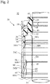
Fig. 2 is a cross-sectional view showing the sealing device according to the embodiment; -
Fig. 3 is a cross-sectional view showing a usage state of the sealing device according to the embodiment; -
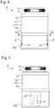
Fig. 4 is a front view showing the sealing device according to the embodiment; -
Fig. 5 is a side view showing the sealing device according to the embodiment; -
Fig. 6 is a cross-sectional view taken along line VI-VI inFig. 4 ; -
Fig. 7 is a perspective view in which a part of the sealing device according to the embodiment is cutaway; -
Fig. 8 is a cross-sectional view showing a state in which the sealing device according to the embodiment is being attached to a guide; and -
Fig. 9 is a cross-sectional view showing a state in which a sealing device according to a modification is being attached to the guide. - Hereinafter, with reference to the accompanying drawings, an embodiment according to the present invention will be described.
- As shown in
Fig. 1 , an internal combustion engine 1 in which the sealing structure according to an embodiment is used includes acylinder head 2. Thecylinder head 2 is located above a cylinder (not shown). A piston (not shown) is located inside the cylinder so as to be able to reciprocate. Thecylinder head 2, the cylinder, and the piston define acombustion chamber 4. An intake port 6 and anexhaust port 8 are formed in thecylinder head 2, and an intake valve 10 and anexhaust valve 12 are located in the intake port 6 and theexhaust port 8, respectively. - Each of the intake valve 10 and the
exhaust valve 12 has a cylindrical valve stem (rod) 14 and avalve head 16 attached to the lower end of thevalve stem 14. Each valve can reciprocate in the axial direction of thevalve stem 14, and thevalve head 16 opens and closes theport 6 or 8 due to the reciprocation. A cylindrical valve-stem guide (guide) 18 that guides the reciprocating motion of eachvalve stem 14 is fixed to thecylinder head 2, whereas thevalve stem 14 is inserted into the valve-stem guide 18. - A
cam follower 20 is attached to the upper end of eachvalve stem 14. Acam 24 attached to thecamshaft 22 is in contact with the upper surface of thecam follower 20. - Furthermore, a
spring seat 26 is attached to the upper end of eachvalve stem 14. Acoil spring 29 is located in a compressed state between thespring seat 26 and aspring seat 28 that is formed on thecylinder head 2. The elastic restoring force of thecoil spring 29 is always exerted in a direction for lifting thevalve stem 14 upward. - In the above configuration, when the
cam 24 pushes down thecam follower 20 against the elastic restoring force of thecoil spring 29 due to the rotation of thecamshaft 22, thevalve stem 14 is lowered, so that theport 6 or 8 is opened. When the force by which thecam 24 pushes down thecam follower 20 decreases due to the rotation of thecam shaft 22, thevalve stem 14 is raised by the elastic restoring force of thecoil spring 29, so that theport 6 or 8 is closed. - The end of the valve-
stem guide 18 and the center of thevalve stem 14 are covered with a valve-stem seal (sealing device) 30. The valve-stem seal 30 allows the engine oil in the surroundingoil chamber 32 to flow into the clearance between thevalve stem 14 and the valve-stem guide 18 (clearance Ga inFigs. 2 and3 ), for lubricating thevalve stem 14 and the valve-stem guide 18. However, in order to reduce or prevent the generation of white smoke caused by engine oil and to reduce the consumption of engine oil, the valve-stem seal 30 appropriately suppresses the amount of engine oil flowing into the clearance between thevalve stem 14 and the valve-stem guide 18. - With reference to
Figs. 2 to 7 , the sealing structure including the valve-stem seal 30 and the valve-stem guide 18 will be described in more detail.Fig. 2 shows the valve-stem seal 30 that is not in contact with thevalve stem 14 and the valve-stem guide 18, and inFig. 2 , thevalve stem 14 and the valve-stem guide 18 are indicated by phantom lines for reference.Fig. 3 shows the valve-stem seal 30 in use that is in contact with thevalve stem 14 and the valve-stem guide 18. Although the valve-stem seal 30 and the valve-stem guide 18 have cylindrical shapes, only their left side portions are shown inFigs. 2 and3 . -
Fig. 4 is a front view showing the valve-stem seal 30.Fig. 5 is a side view showing the valve-stem seal 30.Fig. 6 is a cross-sectional view taken along the line VI-VI inFig. 4 , and shows not only the cross section of the valve-stem seal 30, but also the cross section of the valve-stem guide 18. - As shown in
Figs. 2 and3 , the inner peripheral surface of the valve-stem guide 18 is spaced apart with a clearance Ga from the outer peripheral surface of thevalve stem 14. A high pressure in the combustion chamber 4 (hereinafter referred to as "back pressure") is applied to the valve-stem seal 30 through the clearance Ga. In particular, a high back pressure in the exhaust stroke is applied to the valve-stem seal 30 provided in theexhaust port 8. - The valve-
stem seal 30 has a double structure having anelastic ring 34 and arigid ring 36. Theelastic ring 34 is made of an elastic material (for example, an elastomer). Therigid ring 36 is formed of a rigid material (for example, metal), and is brought into close contact with theelastic ring 34 to reinforce theelastic ring 34. - The
elastic ring 34 includes an elastic-ringcylindrical part 38, an inner circularannular part 40, and a connecting circularannular part 42. The valve-stem guide 18 is fitted into the elastic-ringcylindrical part 38 by an interference fit manner. Therefore, the inner peripheral surface of the elastic-ringcylindrical part 38 is in contact with the outer peripheral surface of the valve-stem guide 18. - Protruding annular-
wall portion cylindrical part 38. Each protruding annular-wall portion is a protrusion that is continuous in the circumferential direction. In a case in which the valve-stem guide 18 is engaged into the elastic-ringcylindrical part 38, the protruding annular-wall portions Fig. 2 shows the valve-stem guide 18 by phantom lines and shows the protruding annular-wall portions Fig. 3 shows the projectingannular wall portions stem seal 30 is attached to the valve-stem guide 18. - The inner
annular part 40 is located above the elastic-ringcylindrical part 38 and has a smaller outer diameter and a smaller inner diameter in comparison with the elastic-ringcylindrical part 38. - The connecting circular
annular part 42 connects the upper end of the elastic-ringcylindrical part 38 and the inner circularannular part 40. The end surface of the valve-stem guide 18 is in contact with the connecting circularannular part 42. - A
main lip 44, a back-pressure lip 46, andmultiple protrusions 48 are formed on the innerannular part 40. The outer peripheral surface of thevalve stem 14 is slidably in contact with themain lip 44 and the back-pressure lip 46. Themain lip 44 is mainly provided so that engine oil in theoil chamber 32 does not flow excessively toward the valve-stem guide 18. The back-pressure lip 46 is provided for receiving the back pressure applied to the valve-stem seal 30 through the clearance Ga between thevalve stem 14 and the valve-stem guide 18 so that themain lip 44 is not excessively deformed by an excessive back pressure.Multiple protrusions 48 are intermittently arranged in the circumferential direction so as to surround thevalve stem 14. Theseprotrusions 48 are provided so that themain lip 44 and the back-pressure lip 46 are in contact with thevalve stem 14 at a substantially uniform contact pressure over the entire circumference of thevalve stem 14 in the state in which the valve-stem seal 30 is attached to the valve-stem guide 18. - As shown in
Fig. 3 , when in contact with thevalve stem 14, themain lip 44 and the back-pressure lip 46 are deformed and in contact with the outer peripheral surface of thevalve stem 14 over the entire circumference. However, in order to supply an appropriate amount of engine oil to the clearance Ga between thevalve stem 14 and the valve-stem guide 18, minute gaps (not shown) are provided between themain lip 44 and the outer peripheral surface of thevalve stem 14, and minute gaps (not shown) are also provided between the back-pressure lip 46 and the outer peripheral surface of thevalve stem 14. - Although not necessary, a
garter spring 50 may be wound around the innerannular part 40, as shown inFig. 3 . In this embodiment, acircumferential groove 52 that receives thegarter spring 50 is formed on the outer circumferential surface of the innerannular part 40. Thegarter spring 50 presses themain lip 44 and theprotrusions 48 inward to increase the contact pressure of themain lip 44 and theprotrusions 48 against thevalve stem 14. - The
rigid ring 36 includes a rigid-ringcylindrical part 54 and a circular annular part 56. The rigid-ringcylindrical part 54 is fixed to the outer peripheral surface of the elastic-ringcylindrical part 38 of theelastic ring 34. Therefore, the elastic-ringcylindrical part 38 of theelastic ring 34 is surrounded by the rigid-ringcylindrical part 54 of therigid ring 36 over the entire circumference, and movement or expansion of the elastic-ringcylindrical part 38 in the radial direction is restricted. The circular annular part 56 is fixed to the innerannular part 40 and the connectingannular portion 42 of theelastic ring 34. - The rigid-ring
cylindrical part 54 has a small-diametercylindrical portion 54A, a large-diametercylindrical portion 54B, and a connecting truncated-cone portion 54C. These are arranged coaxially with one another. The large-diametercylindrical portion 54B has a larger outer diameter and a larger inner diameter in comparison with the small-diametercylindrical portion 54A. The connecting truncated-cone portion 54C smoothly connects the small-diametercylindrical portion 54A with the large-diametercylindrical portion 54B. - The small-diameter
cylindrical portion 54A is arranged closer to theelastic ring 34 than the large-diametercylindrical portion 54B, is fixed to the outer peripheral surface of the elastic-ringcylindrical part 38 of theelastic ring 34, and surrounds the elastic-ringcylindrical part 38 over the entire circumference. The connectingtruncated cone part 54C and the large-diametercylindrical portion 54B are arranged at positions away from theelastic ring 34. - At least one
recess 58 is formed on the outer peripheral surface of the valve-stem guide 18. In this embodiment, therecess 58 is one circumferential groove that is continuous in the circumferential direction of the valve-stem guide 18. - Multiple hook hasps 60 are intermittently formed along the circumferential direction on the large-diameter
cylindrical portion 54B of the rigid-ringcylindrical part 54. As shown inFigs. 4 and6 , in this embodiment, the number of hook hasps 60 is two, but it may be three or more. Preferably, as shown inFigs. 4 and6 , these hook hasps 60 are arranged at equiangular intervals in the circumferential direction. However, the angular intervals of the hook hasps 60 may be unequal. - As shown in
Figs. 2 and3 , eachhook hasp 60 has aroot portion 60A and adistal end portion 60B. Theroot portion 60A is a part of the large-diametercylindrical portion 54B, and eachhook hasp 60 extends radially inward and upward (to the side of the main lip 44) from theroot portion 60A, in which thedistal end portion 60B is engaged in therecess 58 of the valve-stem guide 18. - In this embodiment, the
recess 58 of the valve-stem guide 18 is a single circumferential groove that is continuous in the circumferential direction, butmultiple recesses 58 may be formed in the circumferential direction on the outer peripheral surface of the valve-stem guide 18 intermittently (only at the positions into which thehook hasp 60 are engaged). - Since each
hook hasp 60 is engaged in therecess 58 of the valve-stem guide 18, even when a high back pressure is applied to the valve-stem seal 30 through the clearance Ga between thevalve stem 14 and the valve-stem guide 18, the valve-stem seal 30 is unlikely to come off from the valve-stem guide 18. In other words, the hook hasps 60 function as locks for the valve-stem seal 30. - A
groove 62 is formed on the radially inner surface of theroot portion 60A of thehook hasp 60, whereby athin portion 64 thinner than other parts of the hook hasp is formed on theroot portion 60A. Therefore, thehook hasp 60 has greater flexibility in thethin portion 64 than in other parts. - As shown in
Figs. 4 to 7 , slits 66 each defining the contour of thehook hasp 60 are formed in the large-diametercylindrical portion 54B of the rigid-ringcylindrical part 54. Theslits 66 penetrate the large-diametercylindrical portion 54B. As shown inFig. 5 , theslit 66 has a substantially inverted U shape and surrounds thehook hasp 60, which is substantially rectangular, in three directions. - As shown in
Fig. 7 ,grooves 68 are formed at positions at which there is nohook hasp 60 on the inner peripheral surface of the large-diametercylindrical portion 54B of the rigid-ringcylindrical part 54. Thegrooves 68 cooperate with thegrooves 62 of theroot portions 60A of the hook hasps 60 to constitute a singlecircumferential groove 70 that is continuous in the circumferential direction of the large-diametercylindrical portion 54B. In other words, thecircumferential groove 70 is divided by theslits 66, whereby thegrooves 62 and thegrooves 68 are formed. -
Fig. 8 shows ahook hasp 60 when the valve-stem seal 30 is being attached to the valve-stem guide 18, that is, when the valve-stem guide 18 is fitted into the valve-stem seal 30. At this time, thedistal end portion 60B is slid on the outer peripheral surface of the valve-stem guide 18, as indicated by the arrow until thedistal end portion 60B of thehook hasp 60 enters therecess 58 as indicated by the phantom line. At this time, thehook hasp 60, particularly thethin portion 64 is bent, so that the outer peripheral surface of the valve-stem guide 18 is unlikely to be damaged. As indicated by the phantom line, once thedistal end portion 60B of thehook hasp 60 is engaged into therecess 58, thehook hasp 60 is unlikely to come off from therecess 58, so that even if a high back pressure is applied to the valve-stem seal 30 in the direction opposite to the arrow in the figure, the valve-stem seal 30 is unlikely to come off from the valve-stem guide 18. - In this embodiment, the rigid-ring
cylindrical part 54 includes the small-diameter cylindrical portion 54Aand the large-diametercylindrical portion 54B, in which the hook hasps 60 are formed in the large-diametercylindrical portion 54B. The large-diametercylindrical portion 54B is located farther from the outer peripheral surface of the valve-stem guide 18 than the small-diametercylindrical portion 54A. After the hook hasps 60 are formed on the rigid-ringcylindrical part 54, there is a likelihood that burrs 72 remain on the inner peripheral surface of the rigid-ringcylindrical part 54. However, since the hook hasps 60 are formed in the large-diametercylindrical portion 54B, even if theburrs 72 remain in the large-diametercylindrical portion 54B, when the valve-stem seal 30 is attached to the valve-stem guide 18, theburrs 72 are unlikely to come into contact with the outer peripheral surface of the valve-stem guide 18, and the outer peripheral surface of the valve-stem guide 18 is unlikely to be damaged. - In the embodiment, as shown in
Fig. 8 , thegroove 62 is formed on the radially inner surface of theroot portion 60A of thehook hasp 60, thereby providing thethin portion 64. However, as shown inFig. 9 , thegroove 62 may be formed on the radially outer surface of theroot portion 60A of thehook hasp 60 for providing thethin portion 64. - However, the embodiment in which the
groove 62 is formed on the radial inner surface of theroot portion 60A of thehook hasp 60 as shown inFig. 8 is more advantageous. This is because, at the time of manufacturing therigid ring 36, which will be described later, eachhook hasp 60 can be easily shaped by folding at thegroove 62 as a crease, as compared with the case ofFig. 9 . - Next, a manufacturing method of the valve-
stem seal 30 that is a sealing device, particularly a method of forming the hook hasps 60 of the rigid-ringcylindrical part 54, will be described. - First, the circumferential groove 70 (see
Fig. 7 ) is formed on the inner peripheral surface or the outer peripheral surface of the large-diametercylindrical portion 54B of the rigid-ringcylindrical part 54. Thecircumferential groove 70 may be formed by cutting work, or when therigid ring 36 is manufactured by pressing work or casting work using a mold, thecircumferential groove 70 may also be formed by the mold. - Next, slits 66 for defining the contours of the hook hasps 60 are formed in the large-diameter
cylindrical portion 54B by, for example, cutting work or punching work. Since theslit 66 extends along the longitudinal direction of the rigid-ringcylindrical part 54 and intersects thecircumferential groove 70, thegrooves 62 and thegrooves 68 are left in the large-diametercylindrical portion 54B by the formation of theslits 66. - Then, the hook hasps 60 are folded at the
thin portions 64, in particular, at thegrooves 62, which are the remaining portions of thecircumferential groove 70, as creases. In this way, the hook hasps 60 are formed. - The
elastic ring 34 and therigid ring 36 are integrated before or after the hook hasps 60 are shaped. For example, theelastic ring 34 and therigid ring 36 can be integrated by placing therigid ring 36 inside a mold, putting the material of theelastic ring 34 into the mold, and molding theelastic ring 34 by pressing or injection molding. - In this manufacturing method, the
thin portions 64 of the hook hasps 60 can be formed by forming thecircumferential groove 70 before forming theslits 66 to define the contours of the hook hasps 60. Accordingly, it is easier and more efficient to form thethin portions 64 in comparison with a case in which thethin portions 64 of the hook hasps 60 are formed after the outlines of the hook hasps 60 are defined. - Although an embodiment of the present invention has been described, the foregoing description is not intended to limit the present invention. Various modifications including omission, addition, and substitution of structural elements may be made within the scope of the present invention.
- For example, in the above embodiment, the sealing device is the valve-
stem seal 30 that seals thevalve stem 14 and the valve-stem guide 18. However, the present invention can also be applied to a sealing device that seals a piston (reciprocable rod) a piston guide in a piston-type fuel pump. - The inner peripheral surface of the elastic-ring
cylindrical part 38 of theelastic ring 34 may be coated with a resin material having a small coefficient of friction and which is harder than the elastomer so that the valve-stem guide 18 can be easily fitted into the elastic-ringcylindrical part 38. Examples of such resin materials include polyetheretherketone (PEEK), polyphenylene sulfide (PPS), and polytetrafluoroethylene (PTFE). - At least one of the
main lip 44, the back-pressure lip 46, and theprotrusions 48 of theelastic ring 34 may be coated with such a resin material to reduce abrasion thereof. - Aspects of the present invention are also set out in the following numbered clauses:
- Clause 1. A sealing device for sealing a rod having a cylindrical part and a cylindrical guide that guides reciprocation of the rod in an axial direction of the rod, comprising:
- an elastic ring formed of an elastic material; and
- a rigid ring formed of a rigid material fixed to the elastic ring for reinforcing the elastic ring,
- the elastic ring comprising a lip with which an outer peripheral surface of the rod is in slidable contact,
- the rigid ring comprising a rigid-ring cylindrical part located radially outside an end portion of the guide,
- the rigid-ring cylindrical part comprising multiple hook hasps engaged into at least one recess formed on an outer peripheral surface of the guide,
- each of the multiple hook hasps comprising a root portion and a distal end portion located radially inward of the root portion and fitted into the recess,
- a thin portion being formed at the root portion of the hook hasp, the thin portion being thinner than other parts of the hook hasp.
-
Clause 2. The sealing device according to clause 1, wherein the thin portion is formed by a groove formed on a radially inward surface of the root portion of the hook hasp.
According to this clause, in manufacturing the rigid ring, each hook hasp can be easily fold-shaped at the groove, as compared with a case in which such a groove is formed on a radially outward surface of the root portion. - Clause 3. The sealing device according to
clause 1 or 2, wherein the rigid-ring cylindrical part comprises a small-diameter cylindrical portion and a large-diameter cylindrical portion that is coaxial with the small-diameter cylindrical portion and has an inner diameter greater than that of the small-diameter cylindrical portion, the small-diameter cylindrical portion being arranged closer to the elastic ring than the large-diameter cylindrical portion, the hook hasps being formed in the large-diameter cylindrical portion.
The large-diameter cylindrical portion is located farther from the outer peripheral surface of the guide than the small-diameter cylindrical portion. After the hook hasps are formed on the rigid-ring cylindrical part, there is a likelihood that burrs remain on the inner peripheral surface of the rigid-ring cylindrical part. However, according to this clause, since the hook hasps are formed in the large-diameter cylindrical portion, even if burrs remain in the large-diameter cylindrical portion, when the sealing device is attached to the guide for the bar, the burrs are unlikely to come into contact with the outer peripheral surface of the guide, and the outer peripheral surface of the guide is unlikely to be damaged. -
Clause 4. A method of manufacturing the sealing device according to any one of clauses 1-3, comprising:- forming a circumferential groove that is continuous in a circumferential direction on an inner peripheral surface of the rigid-ring cylindrical part;
- forming slits in the rigid-ring cylindrical part, the slits extending along the longitudinal direction of the rigid-ring cylindrical part and intersecting the circumferential groove for defining contours of the hook hasps; and
- folding the hook hasps at the thin portions corresponding to the circumferential groove.
- In accordance with this clause, the thin portions of the hook hasps can be formed by forming the circumferential groove before forming the slits to define the contours of the hook hasps. Accordingly, it is easier and more efficient to form the thin portions in comparison with a case in which the thin portions of the hook hasps are formed after the outlines of the hook hasps are defined.
-
- 14: Valve Stem (Rod)
- 18: Valve-Stem Guide (Guide)
- 30: Valve-Stem Seal (Sealing Device)
- 32: Oil Chamber
- 34: Elastic Ring
- 36: Rigid Ring
- 38: Elastic-Ring Cylindrical Part
- 44: Main Lip
- 46: Back-Pressure Lip
- 54: Rigid-Ring Cylindrical Part
- 54A: Small-Diameter Cylindrical Portion
- 54B: Large-Diameter Cylindrical Portion
- 54C: Connecting Truncated-Cone Portion
- 60: Hook Hasp
- 60A: Root Portion
- 60B: Distal End Portion
- 62: Groove
- 64: Thin Portion
- 66: Slit
- 70: Circumferential Groove
- Ga: Clearance
Claims (4)
- A sealing device for sealing a rod having a cylindrical part and a cylindrical guide that guides reciprocation of the rod in an axial direction of the rod, comprising:an elastic ring formed of an elastic material; anda rigid ring formed of a rigid material fixed to the elastic ring for reinforcing the elastic ring,the elastic ring comprising a lip with which an outer peripheral surface of the rod is in slidable contact,the rigid ring comprising a rigid-ring cylindrical part located radially outside an end portion of the guide,the rigid-ring cylindrical part comprising multiple hook hasps engaged into at least one recess formed on an outer peripheral surface of the guide,each of the multiple hook hasps comprising a root portion and a distal end portion located radially inward of the root portion and fitted into the recess,a thin portion being formed at the root portion of the hook hasp, the thin portion being thinner than other parts of the hook hasp.
- The sealing device according to claim 1, wherein the thin portion is formed by a groove formed on a radially inward surface of the root portion of the hook hasp.
- The sealing device according to claim 1 or 2, wherein the rigid-ring cylindrical part comprises a small-diameter cylindrical portion and a large-diameter cylindrical portion that is coaxial with the small-diameter cylindrical portion and has an inner diameter greater than that of the small-diameter cylindrical portion, the small-diameter cylindrical portion being arranged closer to the elastic ring than the large-diameter cylindrical portion, the hook hasps being formed in the large-diameter cylindrical portion.
- A method of manufacturing the sealing device according to any one of claims 1-3, comprising:forming a circumferential groove that is continuous in a circumferential direction on an inner peripheral surface of the rigid-ring cylindrical part;forming slits in the rigid-ring cylindrical part, the slits extending along the longitudinal direction of the rigid-ring cylindrical part and intersecting the circumferential groove for defining contours of the hook hasps; andfolding the hook hasps at the thin portions corresponding to the circumferential groove.
Applications Claiming Priority (2)
| Application Number | Priority Date | Filing Date | Title |
|---|---|---|---|
| JP2018026838 | 2018-02-19 | ||
| PCT/JP2019/004223 WO2019159785A1 (en) | 2018-02-19 | 2019-02-06 | Hermetic sealing device and method for manufacturing same |
Publications (2)
| Publication Number | Publication Date |
|---|---|
| EP3757431A1 true EP3757431A1 (en) | 2020-12-30 |
| EP3757431A4 EP3757431A4 (en) | 2021-03-31 |
Family
ID=67619936
Family Applications (1)
| Application Number | Title | Priority Date | Filing Date |
|---|---|---|---|
| EP19755173.2A Withdrawn EP3757431A4 (en) | 2018-02-19 | 2019-02-06 | Hermetic sealing device and method for manufacturing same |
Country Status (5)
| Country | Link |
|---|---|
| US (1) | US11274578B2 (en) |
| EP (1) | EP3757431A4 (en) |
| JP (1) | JP6948452B2 (en) |
| CN (1) | CN111587335B (en) |
| WO (1) | WO2019159785A1 (en) |
Family Cites Families (5)
| Publication number | Priority date | Publication date | Assignee | Title |
|---|---|---|---|---|
| DE19736321A1 (en) * | 1997-08-21 | 1999-03-11 | Cr Elastomere Gmbh | Sealing for machine parts that reciprocate relative to each other |
| JP2002103879A (en) * | 2000-09-29 | 2002-04-09 | Pentel Corp | Writing instrument parts |
| CN104040228B (en) * | 2012-06-25 | 2016-10-05 | 伊格尔工业股份有限公司 | Sealing device |
| EP3098487B1 (en) | 2014-01-22 | 2018-06-20 | Nok Corporation | Valve stem seal |
| JP6346533B2 (en) * | 2014-09-17 | 2018-06-20 | Nok株式会社 | Valve stem seal |
-
2019
- 2019-02-06 CN CN201980007332.3A patent/CN111587335B/en active Active
- 2019-02-06 EP EP19755173.2A patent/EP3757431A4/en not_active Withdrawn
- 2019-02-06 US US16/954,844 patent/US11274578B2/en active Active
- 2019-02-06 WO PCT/JP2019/004223 patent/WO2019159785A1/en not_active Ceased
- 2019-02-06 JP JP2020500432A patent/JP6948452B2/en active Active
Also Published As
| Publication number | Publication date |
|---|---|
| WO2019159785A1 (en) | 2019-08-22 |
| EP3757431A4 (en) | 2021-03-31 |
| CN111587335B (en) | 2022-05-24 |
| CN111587335A (en) | 2020-08-25 |
| JP6948452B2 (en) | 2021-10-13 |
| US11274578B2 (en) | 2022-03-15 |
| JPWO2019159785A1 (en) | 2020-12-03 |
| US20210095581A1 (en) | 2021-04-01 |
Similar Documents
| Publication | Publication Date | Title |
|---|---|---|
| CA2836807C (en) | Eccentricity tolerant valve stem seal assembly | |
| US8800519B2 (en) | Roller tappet | |
| US3829105A (en) | Double cup seal | |
| US10767519B2 (en) | Valve stem seal and hermetic sealing structure | |
| US11274578B2 (en) | Sealing device and manufacturing method therefor | |
| EP1818514A1 (en) | Sealing apparatus | |
| CN110173318B (en) | Sealing device and sealing structure | |
| US20200149656A1 (en) | Valve stem seal | |
| MX2007006509A (en) | Articulating guide seal. | |
| JP2003049743A (en) | Fuel pump for fuel system of internal combustion engine | |
| JP3890750B2 (en) | Valve stem seal | |
| JPWO2019131015A1 (en) | Sealed structure | |
| CN215371246U (en) | Valve stem seal and assembly | |
| EP3312395A1 (en) | A gasket for a valve of an internal combustion engine | |
| CN105378263A (en) | Internal combustion engine fuel, preferably diesel fuel, feed pump assembly | |
| JPH0511285Y2 (en) | ||
| AU2022201961B2 (en) | Valve Stem Seal Structure | |
| JP7344696B2 (en) | Sealed structure | |
| US6877749B2 (en) | Seal for use with a movable rod | |
| US20040200451A1 (en) | Dual spring valve stem seal module | |
| JP2873990B2 (en) | Valve stem sealing device | |
| MXPA04010534A (en) | A cylinder head and gasket for an internal combustion engine. | |
| JP2016223559A (en) | Sealing structure | |
| CN118049324A (en) | Internal combustion engine | |
| JP2016098933A (en) | Valve stem seal |
Legal Events
| Date | Code | Title | Description |
|---|---|---|---|
| STAA | Information on the status of an ep patent application or granted ep patent |
Free format text: STATUS: THE INTERNATIONAL PUBLICATION HAS BEEN MADE |
|
| PUAI | Public reference made under article 153(3) epc to a published international application that has entered the european phase |
Free format text: ORIGINAL CODE: 0009012 |
|
| STAA | Information on the status of an ep patent application or granted ep patent |
Free format text: STATUS: REQUEST FOR EXAMINATION WAS MADE |
|
| 17P | Request for examination filed |
Effective date: 20200605 |
|
| AK | Designated contracting states |
Kind code of ref document: A1 Designated state(s): AL AT BE BG CH CY CZ DE DK EE ES FI FR GB GR HR HU IE IS IT LI LT LU LV MC MK MT NL NO PL PT RO RS SE SI SK SM TR |
|
| AX | Request for extension of the european patent |
Extension state: BA ME |
|
| A4 | Supplementary search report drawn up and despatched |
Effective date: 20210225 |
|
| RIC1 | Information provided on ipc code assigned before grant |
Ipc: F16J 15/3252 20160101ALI20210219BHEP Ipc: F01L 3/08 20060101ALI20210219BHEP Ipc: F16J 15/3232 20160101AFI20210219BHEP Ipc: F16J 15/56 20060101ALI20210219BHEP Ipc: F16J 15/3216 20160101ALI20210219BHEP |
|
| DAV | Request for validation of the european patent (deleted) | ||
| DAX | Request for extension of the european patent (deleted) | ||
| GRAP | Despatch of communication of intention to grant a patent |
Free format text: ORIGINAL CODE: EPIDOSNIGR1 |
|
| STAA | Information on the status of an ep patent application or granted ep patent |
Free format text: STATUS: GRANT OF PATENT IS INTENDED |
|
| INTG | Intention to grant announced |
Effective date: 20220110 |
|
| STAA | Information on the status of an ep patent application or granted ep patent |
Free format text: STATUS: THE APPLICATION IS DEEMED TO BE WITHDRAWN |
|
| 18D | Application deemed to be withdrawn |
Effective date: 20220521 |