EP3757389A1 - Motor cooling systems - Google Patents
Motor cooling systems Download PDFInfo
- Publication number
- EP3757389A1 EP3757389A1 EP19213357.7A EP19213357A EP3757389A1 EP 3757389 A1 EP3757389 A1 EP 3757389A1 EP 19213357 A EP19213357 A EP 19213357A EP 3757389 A1 EP3757389 A1 EP 3757389A1
- Authority
- EP
- European Patent Office
- Prior art keywords
- motor
- compressor
- flow
- pump
- line
- Prior art date
- Legal status (The legal status is an assumption and is not a legal conclusion. Google has not performed a legal analysis and makes no representation as to the accuracy of the status listed.)
- Granted
Links
Images



Classifications
-
- H—ELECTRICITY
- H02—GENERATION; CONVERSION OR DISTRIBUTION OF ELECTRIC POWER
- H02K—DYNAMO-ELECTRIC MACHINES
- H02K9/00—Arrangements for cooling or ventilating
- H02K9/10—Arrangements for cooling or ventilating by gaseous cooling medium flowing in closed circuit, a part of which is external to the machine casing
-
- B—PERFORMING OPERATIONS; TRANSPORTING
- B64—AIRCRAFT; AVIATION; COSMONAUTICS
- B64D—EQUIPMENT FOR FITTING IN OR TO AIRCRAFT; FLIGHT SUITS; PARACHUTES; ARRANGEMENT OR MOUNTING OF POWER PLANTS OR PROPULSION TRANSMISSIONS IN AIRCRAFT
- B64D37/00—Arrangements in connection with fuel supply for power plant
- B64D37/32—Safety measures not otherwise provided for, e.g. preventing explosive conditions
-
- F—MECHANICAL ENGINEERING; LIGHTING; HEATING; WEAPONS; BLASTING
- F04—POSITIVE - DISPLACEMENT MACHINES FOR LIQUIDS; PUMPS FOR LIQUIDS OR ELASTIC FLUIDS
- F04B—POSITIVE-DISPLACEMENT MACHINES FOR LIQUIDS; PUMPS
- F04B39/00—Component parts, details, or accessories, of pumps or pumping systems specially adapted for elastic fluids, not otherwise provided for in, or of interest apart from, groups F04B25/00 - F04B37/00
- F04B39/06—Cooling; Heating; Prevention of freezing
-
- F—MECHANICAL ENGINEERING; LIGHTING; HEATING; WEAPONS; BLASTING
- F04—POSITIVE - DISPLACEMENT MACHINES FOR LIQUIDS; PUMPS FOR LIQUIDS OR ELASTIC FLUIDS
- F04B—POSITIVE-DISPLACEMENT MACHINES FOR LIQUIDS; PUMPS
- F04B9/00—Piston machines or pumps characterised by the driving or driven means to or from their working members
- F04B9/08—Piston machines or pumps characterised by the driving or driven means to or from their working members the means being fluid
-
- F—MECHANICAL ENGINEERING; LIGHTING; HEATING; WEAPONS; BLASTING
- F04—POSITIVE - DISPLACEMENT MACHINES FOR LIQUIDS; PUMPS FOR LIQUIDS OR ELASTIC FLUIDS
- F04B—POSITIVE-DISPLACEMENT MACHINES FOR LIQUIDS; PUMPS
- F04B9/00—Piston machines or pumps characterised by the driving or driven means to or from their working members
- F04B9/08—Piston machines or pumps characterised by the driving or driven means to or from their working members the means being fluid
- F04B9/12—Piston machines or pumps characterised by the driving or driven means to or from their working members the means being fluid the fluid being elastic, e.g. steam or air
-
- F—MECHANICAL ENGINEERING; LIGHTING; HEATING; WEAPONS; BLASTING
- F04—POSITIVE - DISPLACEMENT MACHINES FOR LIQUIDS; PUMPS FOR LIQUIDS OR ELASTIC FLUIDS
- F04B—POSITIVE-DISPLACEMENT MACHINES FOR LIQUIDS; PUMPS
- F04B9/00—Piston machines or pumps characterised by the driving or driven means to or from their working members
- F04B9/08—Piston machines or pumps characterised by the driving or driven means to or from their working members the means being fluid
- F04B9/12—Piston machines or pumps characterised by the driving or driven means to or from their working members the means being fluid the fluid being elastic, e.g. steam or air
- F04B9/1207—Piston machines or pumps characterised by the driving or driven means to or from their working members the means being fluid the fluid being elastic, e.g. steam or air using a source of partial vacuum or sub-atmospheric pressure
-
- F—MECHANICAL ENGINEERING; LIGHTING; HEATING; WEAPONS; BLASTING
- F04—POSITIVE - DISPLACEMENT MACHINES FOR LIQUIDS; PUMPS FOR LIQUIDS OR ELASTIC FLUIDS
- F04D—NON-POSITIVE-DISPLACEMENT PUMPS
- F04D29/00—Details, component parts, or accessories
- F04D29/58—Cooling; Heating; Diminishing heat transfer
- F04D29/5806—Cooling the drive system
-
- F—MECHANICAL ENGINEERING; LIGHTING; HEATING; WEAPONS; BLASTING
- F04—POSITIVE - DISPLACEMENT MACHINES FOR LIQUIDS; PUMPS FOR LIQUIDS OR ELASTIC FLUIDS
- F04D—NON-POSITIVE-DISPLACEMENT PUMPS
- F04D29/00—Details, component parts, or accessories
- F04D29/58—Cooling; Heating; Diminishing heat transfer
- F04D29/582—Cooling; Heating; Diminishing heat transfer specially adapted for elastic fluid pumps
- F04D29/584—Cooling; Heating; Diminishing heat transfer specially adapted for elastic fluid pumps cooling or heating the machine
-
- F—MECHANICAL ENGINEERING; LIGHTING; HEATING; WEAPONS; BLASTING
- F04—POSITIVE - DISPLACEMENT MACHINES FOR LIQUIDS; PUMPS FOR LIQUIDS OR ELASTIC FLUIDS
- F04F—PUMPING OF FLUID BY DIRECT CONTACT OF ANOTHER FLUID OR BY USING INERTIA OF FLUID TO BE PUMPED; SIPHONS
- F04F5/00—Jet pumps, i.e. devices in which flow is induced by pressure drop caused by velocity of another fluid flow
- F04F5/14—Jet pumps, i.e. devices in which flow is induced by pressure drop caused by velocity of another fluid flow the inducing fluid being elastic fluid
- F04F5/16—Jet pumps, i.e. devices in which flow is induced by pressure drop caused by velocity of another fluid flow the inducing fluid being elastic fluid displacing elastic fluids
- F04F5/20—Jet pumps, i.e. devices in which flow is induced by pressure drop caused by velocity of another fluid flow the inducing fluid being elastic fluid displacing elastic fluids for evacuating
Definitions
- This disclosure relates to motor cooling systems, e.g., for aircraft nitrogen generation system motors.
- NGS nitrogen generating systems
- MDC motor driven compressor
- a motor dissipates heat from stationary and rotating electromagnetic components.
- the motor is cooled by airflow over the electromagnetic components.
- the motor uses two cooling sources that uses two cooling ports.
- the first port uses ram air.
- the second port uses pressurized first compressor outlet flow. Pressurized first compressor outlet air is relatively hot and motor cooling can be ineffective at low ram air speeds and/or high ram air temperatures (e.g., during hot day taxi and low altitude descent).
- a system can include a compressor outlet line configured to receive compressor outlet flow from a compressor, a bypass line in fluid communication with the compressor outlet line and a motor outlet line to divert a bypass flow of the compressor outlet flow.
- the system can include at least one pump in fluid communication between the bypass line and the motor outlet line such that the bypass flow at least partially drives the pump to pull cooling air flow through a motor to cool the motor.
- the pump can be a passive pump that has no moving parts.
- the pump can be an ejector pump configured to create a pressure drop by effusing bypass flow into or downstream of the motor outlet line. Any other suitable pump is contemplated herein.
- the cooling flow can be drawn from ram air flow.
- the system can include at least one valve disposed between the compressor outlet line and the bypass line.
- the valve can be disposed on the bypass line.
- the valve can be configured to modify bypass flow.
- the valve is configured to turn bypass flow on or off.
- the valve can be configured to meter bypass flow.
- the system can include the motor and the compressor.
- the compressor can be connected to the motor to be driven by the motor, for example.
- the system can include a heat exchanger in fluid communication with the compressor outlet line.
- the system can include a second compressor connected to the motor to be driven by the motor and in fluid communication with the heat exchanger to receive flow from the heat exchanger.
- the system can include a ram air inlet line in fluid communication with the motor such that air passes from the ram air inlet line, through the motor, to the motor outlet line to receive heat at least from motor stator windings.
- a method can include bleeding compressor air from a compressor outlet line to drive at least one pump configured to pull cooling flow through a motor.
- the method can include driving a compressor in fluid communication with the compressor outlet line using the motor.
- the pump can be any pump disclosed herein, e.g., described above, for example.
- the method can include controlling at least one valve to modify an amount of bleeding of compressor air. In certain embodiments, the method can include pulling ram air through the motor using the pump.
- the method can include fully opening the valve on when on the ground.
- the method can include closing the valve (e.g., at least partially if not fully) when in flight.
- FIG. 1 an illustrative view of an embodiment of a system in accordance with the disclosure is shown in Fig. 1 and is designated generally by reference character 100.
- FIGs. 2-6 Other embodiments and/or aspects of this disclosure are shown in Figs. 2-6 .
- Certain embodiments described herein can be used, e.g., to improve cooling of a motor during ground operation, for example.
- a system 100 can include a compressor outlet line 101 configured to receive compressor outlet flow 102 from a compressor 103.
- the system 100 can include a bypass line 105 in fluid communication with the compressor outlet line 101 and a motor outlet line 107 to divert a bypass flow 109 of the compressor outlet flow 102.
- the system 100 can include at least one pump 111 in fluid communication between the bypass line 105 and the motor outlet line 107 such that the bypass flow 109 at least partially drives the pump 111 to pull cooling flow 112 through a motor 113 to cool the motor 113.
- the pump 111 can be connected (e.g., directly or indirectly) to the motor outlet line 107 or disposed within the motor outlet line 107, for example, such that the pump 111 is in fluid communication with a cooling flow outlet of the motor 113.
- the pump 111 can be a passive pump that has no moving parts.
- the pump 111 can be an ejector pump (e.g., as shown in Figs. 1 and 3 ) configured to create a pressure drop by effusing bypass flow 109 into or downstream of the motor outlet line 107 as shown.
- Any other suitable pump e.g., a turbine or any other active pump is contemplated herein.
- the cooling flow 112 can be or include ram air, for example. Any other suitable source for cooling flow for at least a portion of the cooling flow 112 is contemplated herein.
- ram air can be the cooling flow 112 for cooling a stator of the motor 113
- gap cooling of the motor 113 can be from a different source (e.g., a heat exchanger pack).
- the pump 111 can be configured to pull from one or multiple sources of cooling flow 112 (e.g., only the ram air and not pack flow, both ram air and pack flow). For example, as shown in Fig. 2 , the pump 111 pulling from a ram air source 214a to cool a stator and from a pack source 214b to provide gap cooling.
- the system 100 can include at least one valve 115 disposed between the compressor outlet line 101 and at least a portion of the bypass line 115.
- the valve 115 can be disposed on the bypass line 105 as shown.
- the valve 115 can be configured to modify bypass flow 109.
- the valve 115 configured to turn bypass flow 109 on or off.
- the valve 115 can be configured to meter bypass flow 109 (e.g., to be able to produce any desired amount of bypass flow 109).
- the system 100 can include the motor 113 and the compressor 103.
- the compressor 103 can be connected to the motor 113 to be driven by the motor 113, for example.
- the system 100 can include a heat exchanger 117 (e.g., a heat exchanger pack) in fluid communication with the compressor outlet line 101, e.g., to receive compressor outlet flow 102 for transferring heat from the compressor outlet flow 102.
- a heat exchanger 117 e.g., a heat exchanger pack
- the system 100 can include a second compressor 119 connected to the motor 113 to be driven by the motor 113 and in fluid communication with the heat exchanger 117 to receive flow from the heat exchanger 117.
- the system 100 can include a ram air inlet line 121 in fluid communication with the motor 113 (e.g., at a cooling flow inlet of the motor 113) such that air passes from the ram air inlet line 121, through the motor 113, to the motor outlet line 107 to receive heat at least from motor stator windings, for example.
- cooling flow lines, pumps, valves, and/or any other suitable components are contemplated herein.
- the pump 111 can be disposed in the ram air inlet line 121 in addition to or instead of downstream of the motor 113 as shown.
- Any suitable number of pumps, valves, and flow paths are contemplated herein.
- Any suitable system 100 can be utilized as part of an NGS system for inerting aircraft fuel tanks, for example. Any other suitable use is contemplated herein.
- a method can include bleeding compressor air from a compressor outlet line to drive at least one pump configured to pull cooling flow through a motor.
- the method can include driving a compressor in fluid communication with the compressor outlet line using the motor.
- the pump can be any pump disclosed herein, e.g., described above, for example.
- the method can include controlling at least one valve to modify an amount of bleeding of compressor air. In certain embodiments, the method can include pulling ram air through the motor using the pump.
- the method can include fully opening the valve on when on the ground.
- the method can include closing the valve (e.g., at least partially if not fully) when in flight.
- Embodiments provide motor cooling using ejector based cooling flow generation.
- Embodiments can utilize bleed from a first compressor to drive the ejector which pulls ram air through.
- An ejector is a velocity driven pump, e.g., flow is sent through the nozzles of ejector and it creates a pressure drop (e.g., downstream of the motor 113).
- An ejector can be placed inside ram air ducting connected to an exhaust, for example.
- Thermal analysis assumptions are shown on Fig. 4 . Thermal analyses results are shown in Figs. 5 and 6 .
- Case 1 (shown in Fig. 5 ) is analyzed with traditional motor cooling configuration.
- Traditional motors for an NGS system generate 41-42KW of power, and spins two compressors on the same shaft.
- the first compressor is larger than the second compressor to extract cooling flow to keep the motor itself cool.
- the temperature coming out of this compressor is too high to cool the motor stator, and needs to be cooled, so below 1,500 feet (457 m), pressurized air from first compressor is cooled in the heat exchanger and used for motor stator and gap cooling. This air is at about 221 degrees F (105 deg.
- Case 2 assumes a configuration in accordance with at least one embodiment of this disclosure (e.g., an ejector based motor cooling configuration). Assuming an ejector pump provides about 50% of the flow rate, case 2 (e.g., shown in Fig. 6 ) is analyzed with ram air flow pulled by a pump through the motor stator. This assumes about 4.5 PPM cooling flow for stator cooling at inlet temperature of 103 degrees F (39.4 deg. C). Gap cooling flow is about 4.4 PPM at 177 degrees F (80.6 deg. C) inlet temperature. In this case, the maximum stator temperature was seen to be 158 degrees C, and the maximum rotor temperature was seen to be 140 degrees C.
- case 2 assumes a configuration in accordance with at least one embodiment of this disclosure (e.g., an ejector based motor cooling configuration). Assuming an ejector pump provides about 50% of the flow rate, case 2 (e.g., shown in Fig. 6 ) is analyzed with ram
- stator temperature was reduced by 22 degrees C, and rotor temperature decreased by 50 degrees C.
- ram air inlet air can be 103 degrees F (39.4 deg. C)
- embodiments still perform better than traditional systems.
- certain embodiments of this disclosure can utilize airflow from ram air which is significantly cooler than the cooling flow source used by the traditional system and makes the entire system more efficient.
- Embodiments can allow ram air to be used for motor cooling for the entire range of altitudes of an aircraft.
- Embodiments also provide a gap cooling flow increase and a gap cooling inlet flow temperature reduction, which provides additional benefit to motor cooling.
- Embodiments require lower power to drive the motor, and thus, less heat is generated which allows a lighter, smaller system overall.
- the motor input power can be reduced from 34 kW to 30.6 kW, which means lower motor loss and lower motor winding temperature.
- lower electrical power consumption will increase efficiency of the NGS system.
- This reduction of motor power has not been incorporated in thermal analysis. Incorporation of reduced motor power in thermal analysis will result in further reduction in motor winding temperature than what is shown in Figs. 4-6 .
- Embodiments also do not require the complex multiple valve/flow path scheme of traditional systems.
- Embodiments provide an improved thermal performance and higher reliability of NGS MDC motor.
- a 22 degree C reduction increases reliability by about 4 times.
- any numerical values disclosed herein can be exact values or can be values within a range. Further, any terms of approximation (e.g., “about”, “approximately”, “around”) used in this disclosure can mean the stated value within a range. For example, in certain embodiments, the range can be within (plus or minus) 20%, or within 10%, or within 5%, or within 2%, or within any other suitable percentage or number as appreciated by those having ordinary skill in the art (e.g., for known tolerance limits or error ranges).
Landscapes
- Engineering & Computer Science (AREA)
- Mechanical Engineering (AREA)
- General Engineering & Computer Science (AREA)
- Physics & Mathematics (AREA)
- Thermal Sciences (AREA)
- Power Engineering (AREA)
- Fluid Mechanics (AREA)
- Aviation & Aerospace Engineering (AREA)
- Life Sciences & Earth Sciences (AREA)
- Atmospheric Sciences (AREA)
- Motor Or Generator Cooling System (AREA)
Abstract
Description
- This disclosure relates to motor cooling systems, e.g., for aircraft nitrogen generation system motors.
- In traditional nitrogen generating systems (NGS), e.g., for inerting aircraft fuel tanks, a motor driven compressor (MDC) is used. A motor dissipates heat from stationary and rotating electromagnetic components. The motor is cooled by airflow over the electromagnetic components. The motor uses two cooling sources that uses two cooling ports. The first port uses ram air. The second port uses pressurized first compressor outlet flow. Pressurized first compressor outlet air is relatively hot and motor cooling can be ineffective at low ram air speeds and/or high ram air temperatures (e.g., during hot day taxi and low altitude descent).
- Such conventional methods and systems have generally been considered satisfactory for their intended purpose. However, there is still a need in the art for improved motor cooling systems. The present disclosure provides a solution for this need.
- A system can include a compressor outlet line configured to receive compressor outlet flow from a compressor, a bypass line in fluid communication with the compressor outlet line and a motor outlet line to divert a bypass flow of the compressor outlet flow. The system can include at least one pump in fluid communication between the bypass line and the motor outlet line such that the bypass flow at least partially drives the pump to pull cooling air flow through a motor to cool the motor.
- The pump can be a passive pump that has no moving parts. For example, the pump can be an ejector pump configured to create a pressure drop by effusing bypass flow into or downstream of the motor outlet line. Any other suitable pump is contemplated herein. The cooling flow can be drawn from ram air flow.
- In certain embodiments, the system can include at least one valve disposed between the compressor outlet line and the bypass line. For example, the valve can be disposed on the bypass line.
- The valve can be configured to modify bypass flow. For example, the valve is configured to turn bypass flow on or off. The valve can be configured to meter bypass flow.
- In certain embodiments, the system can include the motor and the compressor. The compressor can be connected to the motor to be driven by the motor, for example. In certain embodiments, the system can include a heat exchanger in fluid communication with the compressor outlet line. In certain embodiments, the system can include a second compressor connected to the motor to be driven by the motor and in fluid communication with the heat exchanger to receive flow from the heat exchanger. In certain embodiments, the system can include a ram air inlet line in fluid communication with the motor such that air passes from the ram air inlet line, through the motor, to the motor outlet line to receive heat at least from motor stator windings.
- In accordance with at least one aspect of this disclosure, a method can include bleeding compressor air from a compressor outlet line to drive at least one pump configured to pull cooling flow through a motor. The method can include driving a compressor in fluid communication with the compressor outlet line using the motor. The pump can be any pump disclosed herein, e.g., described above, for example.
- In certain embodiments, the method can include controlling at least one valve to modify an amount of bleeding of compressor air. In certain embodiments, the method can include pulling ram air through the motor using the pump.
- In certain embodiments, the method can include fully opening the valve on when on the ground. The method can include closing the valve (e.g., at least partially if not fully) when in flight.
- These and other features of the embodiments of the subject disclosure will become more readily apparent to those skilled in the art from the following detailed description taken in conjunction with the drawings.
- So that those skilled in the art to which the subject disclosure appertains will readily understand how to make and use the devices and methods of the subject disclosure without undue experimentation, embodiments thereof will be described in detail herein below with reference to certain figures, wherein:
-
Fig. 1 is a schematic diagram of an embodiment of a system in accordance with this disclosure; -
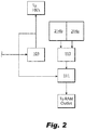
Fig. 2 is a flow diagram of the system ofFig. 1 ; -
Fig. 3 is a schematic view of an embodiment of at least one pump of the system ofFig. 1 ; -
Fig. 4 shows thermal analysis assumptions for thermal analysis of one or more embodiments of a system; -
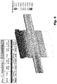
Fig. 5 shows a thermal and flow analysis of a motor using a first cooling system; and -
Fig. 6 shows a thermal and flow analysis of a motor using the system ofFig. 1 . - Reference will now be made to the drawings wherein like reference numerals identify similar structural features or aspects of the subject disclosure. For purposes of explanation and illustration, and not limitation, an illustrative view of an embodiment of a system in accordance with the disclosure is shown in
Fig. 1 and is designated generally byreference character 100. Other embodiments and/or aspects of this disclosure are shown inFigs. 2-6 . Certain embodiments described herein can be used, e.g., to improve cooling of a motor during ground operation, for example. - Referring to
Fig. 1 , asystem 100 can include acompressor outlet line 101 configured to receivecompressor outlet flow 102 from acompressor 103. Thesystem 100 can include abypass line 105 in fluid communication with thecompressor outlet line 101 and amotor outlet line 107 to divert abypass flow 109 of thecompressor outlet flow 102. - Referring additionally to
Figs. 2 and3 , thesystem 100 can include at least onepump 111 in fluid communication between thebypass line 105 and themotor outlet line 107 such that thebypass flow 109 at least partially drives thepump 111 to pullcooling flow 112 through amotor 113 to cool themotor 113. Thepump 111 can be connected (e.g., directly or indirectly) to themotor outlet line 107 or disposed within themotor outlet line 107, for example, such that thepump 111 is in fluid communication with a cooling flow outlet of themotor 113. - In certain embodiments, the
pump 111 can be a passive pump that has no moving parts. For example, thepump 111 can be an ejector pump (e.g., as shown inFigs. 1 and3 ) configured to create a pressure drop by effusingbypass flow 109 into or downstream of themotor outlet line 107 as shown. Any other suitable pump (e.g., a turbine or any other active pump) is contemplated herein. - The
cooling flow 112 can be or include ram air, for example. Any other suitable source for cooling flow for at least a portion of thecooling flow 112 is contemplated herein. For example, it is contemplated that ram air can be thecooling flow 112 for cooling a stator of themotor 113, and gap cooling of themotor 113 can be from a different source (e.g., a heat exchanger pack). Thepump 111 can be configured to pull from one or multiple sources of cooling flow 112 (e.g., only the ram air and not pack flow, both ram air and pack flow). For example, as shown inFig. 2 , thepump 111 pulling from aram air source 214a to cool a stator and from apack source 214b to provide gap cooling. - In certain embodiments, the
system 100 can include at least onevalve 115 disposed between thecompressor outlet line 101 and at least a portion of thebypass line 115. For example, thevalve 115 can be disposed on thebypass line 105 as shown. - The
valve 115 can be configured to modifybypass flow 109. For example, thevalve 115 configured to turnbypass flow 109 on or off. In certain embodiments, thevalve 115 can be configured to meter bypass flow 109 (e.g., to be able to produce any desired amount of bypass flow 109). - In certain embodiments, the
system 100 can include themotor 113 and thecompressor 103. Thecompressor 103 can be connected to themotor 113 to be driven by themotor 113, for example. In certain embodiments, thesystem 100 can include a heat exchanger 117 (e.g., a heat exchanger pack) in fluid communication with thecompressor outlet line 101, e.g., to receivecompressor outlet flow 102 for transferring heat from thecompressor outlet flow 102. - In certain embodiments, the
system 100 can include asecond compressor 119 connected to themotor 113 to be driven by themotor 113 and in fluid communication with theheat exchanger 117 to receive flow from theheat exchanger 117. In certain embodiments, thesystem 100 can include a ramair inlet line 121 in fluid communication with the motor 113 (e.g., at a cooling flow inlet of the motor 113) such that air passes from the ramair inlet line 121, through themotor 113, to themotor outlet line 107 to receive heat at least from motor stator windings, for example. - Any other suitable arrangement of cooling flow lines, pumps, valves, and/or any other suitable components are contemplated herein. For example, it is contemplated that the
pump 111 can be disposed in the ramair inlet line 121 in addition to or instead of downstream of themotor 113 as shown. Any suitable number of pumps, valves, and flow paths are contemplated herein. - Any
suitable system 100 can be utilized as part of an NGS system for inerting aircraft fuel tanks, for example. Any other suitable use is contemplated herein. - In accordance with at least one aspect of this disclosure, a method can include bleeding compressor air from a compressor outlet line to drive at least one pump configured to pull cooling flow through a motor. The method can include driving a compressor in fluid communication with the compressor outlet line using the motor. The pump can be any pump disclosed herein, e.g., described above, for example.
- In certain embodiments, the method can include controlling at least one valve to modify an amount of bleeding of compressor air. In certain embodiments, the method can include pulling ram air through the motor using the pump.
- In certain embodiments, the method can include fully opening the valve on when on the ground. The method can include closing the valve (e.g., at least partially if not fully) when in flight.
- Certain embodiments provide motor cooling using ejector based cooling flow generation. Embodiments can utilize bleed from a first compressor to drive the ejector which pulls ram air through. An ejector is a velocity driven pump, e.g., flow is sent through the nozzles of ejector and it creates a pressure drop (e.g., downstream of the motor 113). An ejector can be placed inside ram air ducting connected to an exhaust, for example.
- Thermal analysis assumptions are shown on
Fig. 4 . Thermal analyses results are shown inFigs. 5 and6 . A sea level hot day taxi case was analyzed.Case 1, (shown inFig. 5 ) is analyzed with traditional motor cooling configuration. Traditional motors for an NGS system generate 41-42KW of power, and spins two compressors on the same shaft. The first compressor is larger than the second compressor to extract cooling flow to keep the motor itself cool. The temperature coming out of this compressor is too high to cool the motor stator, and needs to be cooled, so below 1,500 feet (457 m), pressurized air from first compressor is cooled in the heat exchanger and used for motor stator and gap cooling. This air is at about 221 degrees F (105 deg. C) motor inlet temperature at hot day sea level which results in very high MDC stator winding temperature (e.g., above 180 deg. C).Case 1 assumes about 9.6 PPM cooling flow for stator cooling at inlet temperature of 221 degrees F (105 deg. C). Gap cooling flow is assumed at 3.2 PPM at 236 degrees F (113 deg. C) inlet temperature. It was shown that the maximum stator temperature was 180 degrees C, and the maximum rotor temperature was 190 degrees C. - Case 2 assumes a configuration in accordance with at least one embodiment of this disclosure (e.g., an ejector based motor cooling configuration). Assuming an ejector pump provides about 50% of the flow rate, case 2 (e.g., shown in
Fig. 6 ) is analyzed with ram air flow pulled by a pump through the motor stator. This assumes about 4.5 PPM cooling flow for stator cooling at inlet temperature of 103 degrees F (39.4 deg. C). Gap cooling flow is about 4.4 PPM at 177 degrees F (80.6 deg. C) inlet temperature. In this case, the maximum stator temperature was seen to be 158 degrees C, and the maximum rotor temperature was seen to be 140 degrees C. - Maximum stator temperature was reduced by 22 degrees C, and rotor temperature decreased by 50 degrees C. For example, even for a very hot day where ram air inlet air can be 103 degrees F (39.4 deg. C), it is still a significant reduction from 221 degrees F (105 deg. C) inlet temperature of cooling flow used in traditional systems. Even with motor cooling airflow assumed to be reduced based on ejector efficiency, embodiments still perform better than traditional systems.
- As can be seen in the results compared to a traditional system (e.g., shown in
Fig. 5 ), certain embodiments of this disclosure (e.g., as shown inFig. 6 ) can utilize airflow from ram air which is significantly cooler than the cooling flow source used by the traditional system and makes the entire system more efficient. Embodiments can allow ram air to be used for motor cooling for the entire range of altitudes of an aircraft. Embodiments also provide a gap cooling flow increase and a gap cooling inlet flow temperature reduction, which provides additional benefit to motor cooling. - Embodiments require lower power to drive the motor, and thus, less heat is generated which allows a lighter, smaller system overall. The motor input power can be reduced from 34 kW to 30.6 kW, which means lower motor loss and lower motor winding temperature. In addition, lower electrical power consumption will increase efficiency of the NGS system. This reduction of motor power has not been incorporated in thermal analysis. Incorporation of reduced motor power in thermal analysis will result in further reduction in motor winding temperature than what is shown in
Figs. 4-6 . Embodiments also do not require the complex multiple valve/flow path scheme of traditional systems. - Embodiments provide an improved thermal performance and higher reliability of NGS MDC motor. A 22 degree C reduction increases reliability by about 4 times.
- Those having ordinary skill in the art understand that any numerical values disclosed herein can be exact values or can be values within a range. Further, any terms of approximation (e.g., "about", "approximately", "around") used in this disclosure can mean the stated value within a range. For example, in certain embodiments, the range can be within (plus or minus) 20%, or within 10%, or within 5%, or within 2%, or within any other suitable percentage or number as appreciated by those having ordinary skill in the art (e.g., for known tolerance limits or error ranges).
- Any suitable combination(s) of any disclosed embodiments and/or any suitable portion(s) thereof are contemplated herein.
- The embodiments of the present disclosure, as described above and shown in the drawings, provide for improvement in the art to which they pertain. While the subject disclosure includes reference to certain embodiments, those skilled in the art will readily appreciate that changes and/or modifications may be made thereto without departing from the scope of the the invention as defined by the claims.
Claims (15)
- A system, comprising:a compressor outlet line (101) configured to receive compressor outlet flow (102) from a compressor (103);a bypass line (105) in fluid communication with the compressor outlet line and a motor outlet line (107) to divert a bypass flow (109) of the compressor outlet flow; andat least one pump (111) in fluid communication between the bypass line and the motor outlet line such that the bypass flow at least partially drives the pump to pull cooling flow through a motor to cool the motor.
- The system of claim 1, wherein the pump (111) is a passive pump that has no moving parts.
- The system of claim 2, wherein the pump (111) is an ejector pump configured to create a pressure drop by effusing bypass flow into or downstream of the motor outlet line.
- The system of any preceding claim, wherein the cooling flow is ram air.
- The system of any preceding claim, further comprising at least one valve (115) disposed between the compressor outlet line and the bypass line, wherein the valve is configured to modify bypass flow.
- The system of claim 5, wherein the valve is disposed on the bypass line.
- The system of claim 5 or 6, wherein the valve is configured to turn bypass flow on or off and/or wherein the valve is configured to meter bypass flow.
- The system of any preceding claim, further comprising the motor (113) and the compressor (103) connected to the motor to be driven by the motor.
- The system of claim 8, further comprising a heat exchanger (117) in fluid communication with the compressor outlet line.
- The system of claim 8 or 9, further comprising a second compressor (119) connected to the motor to be driven by the motor and in fluid communication with the heat exchanger to receive flow from the heat exchanger.
- The system of claim 8, 9 or 10, further comprising a ram air inlet line (121) in fluid communication with the motor such that air passes from the ram air inlet line, through the motor, to the motor outlet line to receive heat at least from motor stator windings.
- A method, comprising:
bleeding compressor air from a compressor outlet line to drive at least one pump configured to pull cooling flow through a motor. - The method of claim 12, further comprising driving a compressor in fluid communication with the compressor outlet line using the motor.
- The method of claim 12 or 13, further comprising controlling at least one valve to modify an amount of bleeding of compressor air.
- The method of claim 14, further comprising fully opening the valve on when at slow aircraft speed or on the ground, and preferably further comprising closing the valve when in flight.
Applications Claiming Priority (1)
| Application Number | Priority Date | Filing Date | Title |
|---|---|---|---|
| US16/453,296 US11201524B2 (en) | 2019-06-26 | 2019-06-26 | Motor cooling systems |
Publications (2)
| Publication Number | Publication Date |
|---|---|
| EP3757389A1 true EP3757389A1 (en) | 2020-12-30 |
| EP3757389B1 EP3757389B1 (en) | 2022-06-08 |
Family
ID=68771387
Family Applications (1)
| Application Number | Title | Priority Date | Filing Date |
|---|---|---|---|
| EP19213357.7A Active EP3757389B1 (en) | 2019-06-26 | 2019-12-03 | Motor cooling systems |
Country Status (2)
| Country | Link |
|---|---|
| US (1) | US11201524B2 (en) |
| EP (1) | EP3757389B1 (en) |
Families Citing this family (2)
| Publication number | Priority date | Publication date | Assignee | Title |
|---|---|---|---|---|
| JP7547292B2 (en) * | 2021-08-10 | 2024-09-09 | 本田技研工業株式会社 | Combined Power System |
| US12129036B2 (en) | 2022-01-19 | 2024-10-29 | Hamilton Sundstrand Corporation | Component cooling and cooling air flow generation from remote heat exchanger |
Citations (5)
| Publication number | Priority date | Publication date | Assignee | Title |
|---|---|---|---|---|
| JPS5852949A (en) * | 1981-09-24 | 1983-03-29 | 株式会社東芝 | Heat pump device driven by engine |
| SE519324C2 (en) * | 2001-06-28 | 2003-02-11 | Valeo Engine Cooling Ab | Cooling system for air from compressor in engine, comprises two coolers which are cooled by surrounding air and specific flow of liquid |
| US20140331692A1 (en) * | 2013-05-08 | 2014-11-13 | Hamilton Sundstrand Corporation | Self-cooling loop with electric ram fan for motor driven compressor |
| WO2017137498A1 (en) * | 2016-02-12 | 2017-08-17 | Fmc Kongsberg Subsea As | Pump |
| EP3401223A1 (en) * | 2017-05-10 | 2018-11-14 | Hamilton Sundstrand Corporation | Motor cooling utilizing cabin air |
Family Cites Families (7)
| Publication number | Priority date | Publication date | Assignee | Title |
|---|---|---|---|---|
| US3744935A (en) * | 1971-10-07 | 1973-07-10 | Crane Co | Cooling systems for motor driven pumps and the like |
| JP3425308B2 (en) * | 1996-09-17 | 2003-07-14 | 株式会社 日立インダストリイズ | Multistage compressor |
| US9457908B2 (en) | 2012-09-20 | 2016-10-04 | Hamilton Sundstrand Corporation | Self-cooled motor driven compressor |
| US10228168B2 (en) * | 2013-03-25 | 2019-03-12 | Carrier Corporation | Compressor bearing cooling |
| JP6552851B2 (en) * | 2015-03-19 | 2019-07-31 | 三菱重工サーマルシステムズ株式会社 | Compressor driving motor and cooling method thereof |
| EP3374390A1 (en) | 2015-11-13 | 2018-09-19 | Visterra, Inc. | Compositions and methods for treating and preventing influenza |
| BR102017009824B1 (en) * | 2017-05-10 | 2023-12-19 | Fmc Technologies Do Brasil Ltda | SYSTEM FOR GAS CIRCULATION IN ANNULAR SPACES OF ROTARY MACHINES |
-
2019
- 2019-06-26 US US16/453,296 patent/US11201524B2/en active Active
- 2019-12-03 EP EP19213357.7A patent/EP3757389B1/en active Active
Patent Citations (5)
| Publication number | Priority date | Publication date | Assignee | Title |
|---|---|---|---|---|
| JPS5852949A (en) * | 1981-09-24 | 1983-03-29 | 株式会社東芝 | Heat pump device driven by engine |
| SE519324C2 (en) * | 2001-06-28 | 2003-02-11 | Valeo Engine Cooling Ab | Cooling system for air from compressor in engine, comprises two coolers which are cooled by surrounding air and specific flow of liquid |
| US20140331692A1 (en) * | 2013-05-08 | 2014-11-13 | Hamilton Sundstrand Corporation | Self-cooling loop with electric ram fan for motor driven compressor |
| WO2017137498A1 (en) * | 2016-02-12 | 2017-08-17 | Fmc Kongsberg Subsea As | Pump |
| EP3401223A1 (en) * | 2017-05-10 | 2018-11-14 | Hamilton Sundstrand Corporation | Motor cooling utilizing cabin air |
Also Published As
| Publication number | Publication date |
|---|---|
| US20200412205A1 (en) | 2020-12-31 |
| US11201524B2 (en) | 2021-12-14 |
| EP3757389B1 (en) | 2022-06-08 |
Similar Documents
| Publication | Publication Date | Title |
|---|---|---|
| US11384690B2 (en) | System and method of reducing post-shutdown engine temperatures | |
| US20220018262A1 (en) | Mechanically driven air vehicle thermal management device | |
| EP2944767B1 (en) | Fluid system | |
| EP3401223B1 (en) | Motor cooling utilizing cabin air | |
| EP2937287B1 (en) | Environmental control systems utilizing shoestring cycle to maximize efficiency | |
| JP5976396B2 (en) | FLADE turbine cooling and power and thermal management | |
| US8522572B2 (en) | Adaptive power and thermal management system | |
| US10302015B2 (en) | Adaptive turbomachine cooling system | |
| EP2527252A2 (en) | Adaptive power and thermal management system | |
| US9205926B2 (en) | Method and system for feeding and ventilating with air a plant of an aircraft auxiliary power unit | |
| EP3321490B1 (en) | Turbo-generator based bleed air system | |
| EP3103721B1 (en) | Recirculation system for parallel ram heat exchangers | |
| EP3056432B1 (en) | Environmental control system utilizing parallel ram heat exchangers with air cycle machine speed compensation | |
| US10087841B2 (en) | Nacelle equipped with an oil-cooling circuit comprising an intermediate heat exchanger | |
| CN105620756A (en) | Environmental control system utilizing cabin air to drive a power turbine of an air cycle machine | |
| US12606310B2 (en) | Compressed air supply system of aircraft | |
| EP4159988B1 (en) | Ambient air environmental control system | |
| EP3757389B1 (en) | Motor cooling systems | |
| US11390386B2 (en) | System and method for increasing bleed air flow to a heat exchanger with a fluid-driven fluid propeller | |
| US11912417B2 (en) | Air conditioning system with cabin air recovery | |
| EP3321491B1 (en) | Electrically boosted regenerative bleed air system | |
| US20110182723A1 (en) | Turbomachine aircraft propeller | |
| US2581964A (en) | Cooling system for air supplied to compartments of aircraft |
Legal Events
| Date | Code | Title | Description |
|---|---|---|---|
| PUAI | Public reference made under article 153(3) epc to a published international application that has entered the european phase |
Free format text: ORIGINAL CODE: 0009012 |
|
| STAA | Information on the status of an ep patent application or granted ep patent |
Free format text: STATUS: THE APPLICATION HAS BEEN PUBLISHED |
|
| AK | Designated contracting states |
Kind code of ref document: A1 Designated state(s): AL AT BE BG CH CY CZ DE DK EE ES FI FR GB GR HR HU IE IS IT LI LT LU LV MC MK MT NL NO PL PT RO RS SE SI SK SM TR |
|
| AX | Request for extension of the european patent |
Extension state: BA ME |
|
| STAA | Information on the status of an ep patent application or granted ep patent |
Free format text: STATUS: REQUEST FOR EXAMINATION WAS MADE |
|
| 17P | Request for examination filed |
Effective date: 20210630 |
|
| RBV | Designated contracting states (corrected) |
Designated state(s): AL AT BE BG CH CY CZ DE DK EE ES FI FR GB GR HR HU IE IS IT LI LT LU LV MC MK MT NL NO PL PT RO RS SE SI SK SM TR |
|
| STAA | Information on the status of an ep patent application or granted ep patent |
Free format text: STATUS: EXAMINATION IS IN PROGRESS |
|
| 17Q | First examination report despatched |
Effective date: 20210825 |
|
| GRAP | Despatch of communication of intention to grant a patent |
Free format text: ORIGINAL CODE: EPIDOSNIGR1 |
|
| STAA | Information on the status of an ep patent application or granted ep patent |
Free format text: STATUS: GRANT OF PATENT IS INTENDED |
|
| INTG | Intention to grant announced |
Effective date: 20211208 |
|
| RIN1 | Information on inventor provided before grant (corrected) |
Inventor name: MILLOT, CHRISTINA W. Inventor name: PALIULIS, JOHN H. Inventor name: PAL, DEBABRATA |
|
| GRAS | Grant fee paid |
Free format text: ORIGINAL CODE: EPIDOSNIGR3 |
|
| GRAA | (expected) grant |
Free format text: ORIGINAL CODE: 0009210 |
|
| STAA | Information on the status of an ep patent application or granted ep patent |
Free format text: STATUS: THE PATENT HAS BEEN GRANTED |
|
| AK | Designated contracting states |
Kind code of ref document: B1 Designated state(s): AL AT BE BG CH CY CZ DE DK EE ES FI FR GB GR HR HU IE IS IT LI LT LU LV MC MK MT NL NO PL PT RO RS SE SI SK SM TR |
|
| REG | Reference to a national code |
Ref country code: AT Ref legal event code: REF Ref document number: 1497098 Country of ref document: AT Kind code of ref document: T Effective date: 20220615 Ref country code: CH Ref legal event code: EP |
|
| REG | Reference to a national code |
Ref country code: DE Ref legal event code: R096 Ref document number: 602019015639 Country of ref document: DE |
|
| REG | Reference to a national code |
Ref country code: IE Ref legal event code: FG4D |
|
| REG | Reference to a national code |
Ref country code: LT Ref legal event code: MG9D |
|
| REG | Reference to a national code |
Ref country code: NL Ref legal event code: MP Effective date: 20220608 |
|
| PG25 | Lapsed in a contracting state [announced via postgrant information from national office to epo] |
Ref country code: SE Free format text: LAPSE BECAUSE OF FAILURE TO SUBMIT A TRANSLATION OF THE DESCRIPTION OR TO PAY THE FEE WITHIN THE PRESCRIBED TIME-LIMIT Effective date: 20220608 Ref country code: NO Free format text: LAPSE BECAUSE OF FAILURE TO SUBMIT A TRANSLATION OF THE DESCRIPTION OR TO PAY THE FEE WITHIN THE PRESCRIBED TIME-LIMIT Effective date: 20220908 Ref country code: LT Free format text: LAPSE BECAUSE OF FAILURE TO SUBMIT A TRANSLATION OF THE DESCRIPTION OR TO PAY THE FEE WITHIN THE PRESCRIBED TIME-LIMIT Effective date: 20220608 Ref country code: HR Free format text: LAPSE BECAUSE OF FAILURE TO SUBMIT A TRANSLATION OF THE DESCRIPTION OR TO PAY THE FEE WITHIN THE PRESCRIBED TIME-LIMIT Effective date: 20220608 Ref country code: GR Free format text: LAPSE BECAUSE OF FAILURE TO SUBMIT A TRANSLATION OF THE DESCRIPTION OR TO PAY THE FEE WITHIN THE PRESCRIBED TIME-LIMIT Effective date: 20220909 Ref country code: FI Free format text: LAPSE BECAUSE OF FAILURE TO SUBMIT A TRANSLATION OF THE DESCRIPTION OR TO PAY THE FEE WITHIN THE PRESCRIBED TIME-LIMIT Effective date: 20220608 Ref country code: BG Free format text: LAPSE BECAUSE OF FAILURE TO SUBMIT A TRANSLATION OF THE DESCRIPTION OR TO PAY THE FEE WITHIN THE PRESCRIBED TIME-LIMIT Effective date: 20220908 |
|
| REG | Reference to a national code |
Ref country code: AT Ref legal event code: MK05 Ref document number: 1497098 Country of ref document: AT Kind code of ref document: T Effective date: 20220608 |
|
| PG25 | Lapsed in a contracting state [announced via postgrant information from national office to epo] |
Ref country code: RS Free format text: LAPSE BECAUSE OF FAILURE TO SUBMIT A TRANSLATION OF THE DESCRIPTION OR TO PAY THE FEE WITHIN THE PRESCRIBED TIME-LIMIT Effective date: 20220608 Ref country code: LV Free format text: LAPSE BECAUSE OF FAILURE TO SUBMIT A TRANSLATION OF THE DESCRIPTION OR TO PAY THE FEE WITHIN THE PRESCRIBED TIME-LIMIT Effective date: 20220608 |
|
| PG25 | Lapsed in a contracting state [announced via postgrant information from national office to epo] |
Ref country code: NL Free format text: LAPSE BECAUSE OF FAILURE TO SUBMIT A TRANSLATION OF THE DESCRIPTION OR TO PAY THE FEE WITHIN THE PRESCRIBED TIME-LIMIT Effective date: 20220608 |
|
| PG25 | Lapsed in a contracting state [announced via postgrant information from national office to epo] |
Ref country code: SM Free format text: LAPSE BECAUSE OF FAILURE TO SUBMIT A TRANSLATION OF THE DESCRIPTION OR TO PAY THE FEE WITHIN THE PRESCRIBED TIME-LIMIT Effective date: 20220608 Ref country code: SK Free format text: LAPSE BECAUSE OF FAILURE TO SUBMIT A TRANSLATION OF THE DESCRIPTION OR TO PAY THE FEE WITHIN THE PRESCRIBED TIME-LIMIT Effective date: 20220608 Ref country code: RO Free format text: LAPSE BECAUSE OF FAILURE TO SUBMIT A TRANSLATION OF THE DESCRIPTION OR TO PAY THE FEE WITHIN THE PRESCRIBED TIME-LIMIT Effective date: 20220608 Ref country code: PT Free format text: LAPSE BECAUSE OF FAILURE TO SUBMIT A TRANSLATION OF THE DESCRIPTION OR TO PAY THE FEE WITHIN THE PRESCRIBED TIME-LIMIT Effective date: 20221010 Ref country code: ES Free format text: LAPSE BECAUSE OF FAILURE TO SUBMIT A TRANSLATION OF THE DESCRIPTION OR TO PAY THE FEE WITHIN THE PRESCRIBED TIME-LIMIT Effective date: 20220608 Ref country code: EE Free format text: LAPSE BECAUSE OF FAILURE TO SUBMIT A TRANSLATION OF THE DESCRIPTION OR TO PAY THE FEE WITHIN THE PRESCRIBED TIME-LIMIT Effective date: 20220608 Ref country code: CZ Free format text: LAPSE BECAUSE OF FAILURE TO SUBMIT A TRANSLATION OF THE DESCRIPTION OR TO PAY THE FEE WITHIN THE PRESCRIBED TIME-LIMIT Effective date: 20220608 Ref country code: AT Free format text: LAPSE BECAUSE OF FAILURE TO SUBMIT A TRANSLATION OF THE DESCRIPTION OR TO PAY THE FEE WITHIN THE PRESCRIBED TIME-LIMIT Effective date: 20220608 |
|
| PG25 | Lapsed in a contracting state [announced via postgrant information from national office to epo] |
Ref country code: PL Free format text: LAPSE BECAUSE OF FAILURE TO SUBMIT A TRANSLATION OF THE DESCRIPTION OR TO PAY THE FEE WITHIN THE PRESCRIBED TIME-LIMIT Effective date: 20220608 Ref country code: IS Free format text: LAPSE BECAUSE OF FAILURE TO SUBMIT A TRANSLATION OF THE DESCRIPTION OR TO PAY THE FEE WITHIN THE PRESCRIBED TIME-LIMIT Effective date: 20221008 |
|
| REG | Reference to a national code |
Ref country code: DE Ref legal event code: R097 Ref document number: 602019015639 Country of ref document: DE |
|
| PG25 | Lapsed in a contracting state [announced via postgrant information from national office to epo] |
Ref country code: AL Free format text: LAPSE BECAUSE OF FAILURE TO SUBMIT A TRANSLATION OF THE DESCRIPTION OR TO PAY THE FEE WITHIN THE PRESCRIBED TIME-LIMIT Effective date: 20220608 |
|
| PLBE | No opposition filed within time limit |
Free format text: ORIGINAL CODE: 0009261 |
|
| STAA | Information on the status of an ep patent application or granted ep patent |
Free format text: STATUS: NO OPPOSITION FILED WITHIN TIME LIMIT |
|
| PG25 | Lapsed in a contracting state [announced via postgrant information from national office to epo] |
Ref country code: DK Free format text: LAPSE BECAUSE OF FAILURE TO SUBMIT A TRANSLATION OF THE DESCRIPTION OR TO PAY THE FEE WITHIN THE PRESCRIBED TIME-LIMIT Effective date: 20220608 |
|
| 26N | No opposition filed |
Effective date: 20230310 |
|
| PG25 | Lapsed in a contracting state [announced via postgrant information from national office to epo] |
Ref country code: SI Free format text: LAPSE BECAUSE OF FAILURE TO SUBMIT A TRANSLATION OF THE DESCRIPTION OR TO PAY THE FEE WITHIN THE PRESCRIBED TIME-LIMIT Effective date: 20220608 |
|
| P01 | Opt-out of the competence of the unified patent court (upc) registered |
Effective date: 20230603 |
|
| REG | Reference to a national code |
Ref country code: CH Ref legal event code: PL |
|
| REG | Reference to a national code |
Ref country code: BE Ref legal event code: MM Effective date: 20221231 |
|
| PG25 | Lapsed in a contracting state [announced via postgrant information from national office to epo] |
Ref country code: LU Free format text: LAPSE BECAUSE OF NON-PAYMENT OF DUE FEES Effective date: 20221203 |
|
| PG25 | Lapsed in a contracting state [announced via postgrant information from national office to epo] |
Ref country code: LI Free format text: LAPSE BECAUSE OF NON-PAYMENT OF DUE FEES Effective date: 20221231 Ref country code: IE Free format text: LAPSE BECAUSE OF NON-PAYMENT OF DUE FEES Effective date: 20221203 Ref country code: CH Free format text: LAPSE BECAUSE OF NON-PAYMENT OF DUE FEES Effective date: 20221231 |
|
| PG25 | Lapsed in a contracting state [announced via postgrant information from national office to epo] |
Ref country code: BE Free format text: LAPSE BECAUSE OF NON-PAYMENT OF DUE FEES Effective date: 20221231 |
|
| PG25 | Lapsed in a contracting state [announced via postgrant information from national office to epo] |
Ref country code: IT Free format text: LAPSE BECAUSE OF FAILURE TO SUBMIT A TRANSLATION OF THE DESCRIPTION OR TO PAY THE FEE WITHIN THE PRESCRIBED TIME-LIMIT Effective date: 20220608 |
|
| PG25 | Lapsed in a contracting state [announced via postgrant information from national office to epo] |
Ref country code: CY Free format text: LAPSE BECAUSE OF FAILURE TO SUBMIT A TRANSLATION OF THE DESCRIPTION OR TO PAY THE FEE WITHIN THE PRESCRIBED TIME-LIMIT Effective date: 20220608 |
|
| PG25 | Lapsed in a contracting state [announced via postgrant information from national office to epo] |
Ref country code: MK Free format text: LAPSE BECAUSE OF FAILURE TO SUBMIT A TRANSLATION OF THE DESCRIPTION OR TO PAY THE FEE WITHIN THE PRESCRIBED TIME-LIMIT Effective date: 20220608 Ref country code: HU Free format text: LAPSE BECAUSE OF FAILURE TO SUBMIT A TRANSLATION OF THE DESCRIPTION OR TO PAY THE FEE WITHIN THE PRESCRIBED TIME-LIMIT; INVALID AB INITIO Effective date: 20191203 |
|
| PG25 | Lapsed in a contracting state [announced via postgrant information from national office to epo] |
Ref country code: MC Free format text: LAPSE BECAUSE OF FAILURE TO SUBMIT A TRANSLATION OF THE DESCRIPTION OR TO PAY THE FEE WITHIN THE PRESCRIBED TIME-LIMIT Effective date: 20220608 |
|
| PG25 | Lapsed in a contracting state [announced via postgrant information from national office to epo] |
Ref country code: MC Free format text: LAPSE BECAUSE OF FAILURE TO SUBMIT A TRANSLATION OF THE DESCRIPTION OR TO PAY THE FEE WITHIN THE PRESCRIBED TIME-LIMIT Effective date: 20220608 |
|
| PG25 | Lapsed in a contracting state [announced via postgrant information from national office to epo] |
Ref country code: MT Free format text: LAPSE BECAUSE OF FAILURE TO SUBMIT A TRANSLATION OF THE DESCRIPTION OR TO PAY THE FEE WITHIN THE PRESCRIBED TIME-LIMIT Effective date: 20220608 |
|
| PG25 | Lapsed in a contracting state [announced via postgrant information from national office to epo] |
Ref country code: BG Free format text: LAPSE BECAUSE OF FAILURE TO SUBMIT A TRANSLATION OF THE DESCRIPTION OR TO PAY THE FEE WITHIN THE PRESCRIBED TIME-LIMIT Effective date: 20220608 |
|
| PG25 | Lapsed in a contracting state [announced via postgrant information from national office to epo] |
Ref country code: BG Free format text: LAPSE BECAUSE OF FAILURE TO SUBMIT A TRANSLATION OF THE DESCRIPTION OR TO PAY THE FEE WITHIN THE PRESCRIBED TIME-LIMIT Effective date: 20220608 |
|
| PG25 | Lapsed in a contracting state [announced via postgrant information from national office to epo] |
Ref country code: TR Free format text: LAPSE BECAUSE OF FAILURE TO SUBMIT A TRANSLATION OF THE DESCRIPTION OR TO PAY THE FEE WITHIN THE PRESCRIBED TIME-LIMIT Effective date: 20220608 |
|
| PGFP | Annual fee paid to national office [announced via postgrant information from national office to epo] |
Ref country code: DE Payment date: 20251126 Year of fee payment: 7 |
|
| PGFP | Annual fee paid to national office [announced via postgrant information from national office to epo] |
Ref country code: GB Payment date: 20251120 Year of fee payment: 7 |
|
| PGFP | Annual fee paid to national office [announced via postgrant information from national office to epo] |
Ref country code: FR Payment date: 20251120 Year of fee payment: 7 |