EP3757353B1 - Insert for a collector of an active clearance control system of an engine of an aircraft - Google Patents
Insert for a collector of an active clearance control system of an engine of an aircraft Download PDFInfo
- Publication number
- EP3757353B1 EP3757353B1 EP20186864.3A EP20186864A EP3757353B1 EP 3757353 B1 EP3757353 B1 EP 3757353B1 EP 20186864 A EP20186864 A EP 20186864A EP 3757353 B1 EP3757353 B1 EP 3757353B1
- Authority
- EP
- European Patent Office
- Prior art keywords
- engine
- collector
- insert
- manifold
- post
- Prior art date
- Legal status (The legal status is an assumption and is not a legal conclusion. Google has not performed a legal analysis and makes no representation as to the accuracy of the status listed.)
- Active
Links
Images



Classifications
-
- F—MECHANICAL ENGINEERING; LIGHTING; HEATING; WEAPONS; BLASTING
- F01—MACHINES OR ENGINES IN GENERAL; ENGINE PLANTS IN GENERAL; STEAM ENGINES
- F01D—NON-POSITIVE DISPLACEMENT MACHINES OR ENGINES, e.g. STEAM TURBINES
- F01D11/00—Preventing or minimising internal leakage of working-fluid, e.g. between stages
- F01D11/08—Preventing or minimising internal leakage of working-fluid, e.g. between stages for sealing space between rotor blade tips and stator
- F01D11/14—Adjusting or regulating tip-clearance, i.e. distance between rotor-blade tips and stator casing
- F01D11/20—Actively adjusting tip-clearance
- F01D11/24—Actively adjusting tip-clearance by selectively cooling-heating stator or rotor components
-
- F—MECHANICAL ENGINEERING; LIGHTING; HEATING; WEAPONS; BLASTING
- F01—MACHINES OR ENGINES IN GENERAL; ENGINE PLANTS IN GENERAL; STEAM ENGINES
- F01D—NON-POSITIVE DISPLACEMENT MACHINES OR ENGINES, e.g. STEAM TURBINES
- F01D11/00—Preventing or minimising internal leakage of working-fluid, e.g. between stages
- F01D11/005—Sealing means between non relatively rotating elements
-
- F—MECHANICAL ENGINEERING; LIGHTING; HEATING; WEAPONS; BLASTING
- F01—MACHINES OR ENGINES IN GENERAL; ENGINE PLANTS IN GENERAL; STEAM ENGINES
- F01D—NON-POSITIVE DISPLACEMENT MACHINES OR ENGINES, e.g. STEAM TURBINES
- F01D25/00—Component parts, details, or accessories, not provided for in, or of interest apart from, other groups
- F01D25/24—Casings; Casing parts, e.g. diaphragms, casing fastenings
-
- F—MECHANICAL ENGINEERING; LIGHTING; HEATING; WEAPONS; BLASTING
- F05—INDEXING SCHEMES RELATING TO ENGINES OR PUMPS IN VARIOUS SUBCLASSES OF CLASSES F01-F04
- F05D—INDEXING SCHEME FOR ASPECTS RELATING TO NON-POSITIVE-DISPLACEMENT MACHINES OR ENGINES, GAS-TURBINES OR JET-PROPULSION PLANTS
- F05D2220/00—Application
- F05D2220/30—Application in turbines
- F05D2220/32—Application in turbines in gas turbines
-
- F—MECHANICAL ENGINEERING; LIGHTING; HEATING; WEAPONS; BLASTING
- F05—INDEXING SCHEMES RELATING TO ENGINES OR PUMPS IN VARIOUS SUBCLASSES OF CLASSES F01-F04
- F05D—INDEXING SCHEME FOR ASPECTS RELATING TO NON-POSITIVE-DISPLACEMENT MACHINES OR ENGINES, GAS-TURBINES OR JET-PROPULSION PLANTS
- F05D2260/00—Function
- F05D2260/20—Heat transfer, e.g. cooling
Definitions
- Gas turbine engines such as those which power aircraft and industrial equipment, employ a compressor to compress air that is drawn into the engine and a turbine to capture energy associated with the combustion of a fuel-air mixture.
- an engine case may house the turbine section.
- a minimum clearance threshold must be maintained; otherwise, the turbine blades and the engine case (or an associated blade outer air seal) may rub against one another so as to reduce the usable lifetime of these components.
- Active clearance control (ACC) hardware is used to control the temperature of the engine case. For example, supplying cool air to the engine case causes the engine case to contract, thereby decreasing the clearance between the engine case and the turbine blades.
- bleed air 204 is taken from, e.g., the compressor and is supplied to one or more manifolds (e.g., manifolds 212a and 212b) via an inlet pipe 216 and a collector 218.
- the manifolds 212a and 212b are located proximate to, e.g., radially outboard of, a high pressure turbine engine case (not shown) and may dispense at least some of the bleed air 204 onto the case. A portion of the bleed air 204 may be conveyed to other portions/sections of the engine via piping/tubing 224.
- the interface 232 between the collector 218 and the manifolds 212a and 212b may be susceptible to leaking.
- a leak may be caused by a movement/deflection of the collector 218 relative to the manifolds 212a and 212b. Such movement/deflection may be based at least in part on loads (e.g., thermal loads, vibratory loads, etc.) experienced by the engine hardware during engine operation. If a leak were to develop, the ACC system 200 may suffer a supply pressure drop that may result in a loss of closure of the ACC system 200.
- loads e.g., thermal loads, vibratory loads, etc.
- US 6 126 389 A discloses a prior art insert as set forth in the preamble of claim 1.
- an insert configured to be coupled to a collector of an active clearance control system of an engine of an aircraft as recited in claim 1.
- connections are set forth between elements in the following description and in the drawings (the contents of which are included in this disclosure by way of reference). It is noted that these connections are general and, unless specified otherwise, may be direct or indirect and that this specification is not intended to be limiting in this respect.
- a coupling between two or more entities may refer to a direct connection or an indirect connection.
- An indirect connection may incorporate one or more intervening entities.
- apparatuses, systems, and methods are directed to an insert.
- the insert includes a flange/gasket coupled to four or more posts/chimneys.
- a post may be seated within a receptacle formed in a manifold.
- the insert may seal a leak that might otherwise be present between a collector and the manifold, which may assist in the performance (e.g., closure) of an active clearance control (ACC) system.
- ACC active clearance control
- FIG. 1 is a side cutaway illustration of a geared turbine engine 10.
- This turbine engine 10 extends along an axial centerline 12 between an upstream airflow inlet 14 and a downstream airflow exhaust 16.
- the turbine engine 10 includes a fan section 18, a compressor section 19, a combustor section 20 and a turbine section 21.
- the compressor section 19 includes a low pressure compressor (LPC) section 19A and a high pressure compressor (HPC) section 19B.
- the turbine section 21 includes a high pressure turbine (HPT) section 21A and a low pressure turbine (LPT) section 21B.
- the engine sections 18-21 are arranged sequentially along the centerline 12 within an engine housing 22.
- Each of the engine sections 18-19B, 21A and 21B includes a respective rotor 24-28.
- Each of these rotors 24-28 includes a plurality of rotor blades arranged circumferentially around and connected to one or more respective rotor disks.
- the rotor blades may be formed integral with or mechanically fastened, welded, brazed, adhered and/or otherwise attached to the respective rotor disk(s).
- the fan rotor 24 is connected to a gear train 30, for example, through a fan shaft 32.
- the gear train 30 and the LPC rotor 25 are connected to and driven by the LPT rotor 28 through a low speed shaft 33.
- the HPC rotor 26 is connected to and driven by the HPT rotor 27 through a high speed shaft 34.
- the shafts 32-34 are rotatably supported by a plurality of bearings 36; e.g., rolling element and/or thrust bearings. Each of these bearings 36 is connected to the engine housing 22 by at least one stationary structure such as, for example, an annular support strut.
- the air within the core gas path 38 may be referred to as "core air”.
- the air within the bypass gas path 40 may be referred to as "bypass air”.
- the core air is directed through the engine sections 19-21, and exits the turbine engine 10 through the airflow exhaust 16 to provide forward engine thrust.
- fuel is injected into a combustion chamber 42 and mixed with compressed core air. This fuel-core air mixture is ignited to power the turbine engine 10.
- the bypass air is directed through the bypass gas path 40 and out of the turbine engine 10 through a bypass nozzle 44 to provide additional forward engine thrust. This additional forward engine thrust may account for a majority (e.g., more than 70 percent) of total engine thrust.
- at least some of the bypass air may be directed out of the turbine engine 10 through a thrust reverser to provide reverse engine thrust.
- FIG. 1 represents one possible configuration for an engine 10. Aspects of the disclosure may be applied in connection with other environments, including additional configurations for gas turbine engines. Aspects of the disclosure may be applied in connection with non-geared engines.
- a (portion of an) ACC system 300 is shown.
- the system 300 may be incorporated at part of an engine, such as for example the engine 10 of FIG. 1 .
- the system 300 may include a collector 318 and manifolds 312a and 312b.
- the manifolds 312a and 312b and the collector 318 may be made of one or more materials, such as for example stainless steel.
- the collector 318 may be configured to receive a cooling fluid 304.
- the cooling fluid 304 may include air received from one or more sections of an engine (e.g., compressor section 19 of FIG. 1 ).
- one or more of the first manifold 312a, the second manifold 312b, and the collector 318 may move/deflect relative to at least one of the others of the first manifold 312a, the second manifold 312b, and the collector 318.
- the system 300 includes an insert 330 located at the interface between the collector 318, the manifold 312a, and the manifold 312b.
- the insert 330 may be made of one or more materials.
- the insert 330 includes sheet metal.
- the insert 330 includes a flange/gasket 334 that may terminate at a first end in a first post/chimney 338a and at a second end in a second post/chimney 338b.
- the first and second posts 338a and 338b may allow bleed air to pass between the collector 318 and the respective manifold 312a and 312b.
- the flange 334 includes a foam material, that has a large compression capability (e.g., larger than a threshold) to accommodate the movement/deflection described above.
- the post 338a may be seated in a receptacle 342a formed in the manifold 312a.
- the post 338b may be seated in a receptacle 342b formed in the manifold 312b.
- One or more dimensions of the posts 338a and 338b may be based on the loads that the system 300 may experience (which, in turn, may correspond to the amount/degree of movement/deflection that may be experienced over the engine operating range).
- a (radially-oriented) height H A of the post 338a may be selected so as to accommodate a (radially-oriented) movement/deflection of the collector 318 relative to the manifold 312a over the full engine operating range.
- the height H A may be selected to be at least long enough so as to ensure that the post 338a is seated in the receptacle 342a when the collector 318 experiences maximum (radial) separation from the manifold 312a.
- the height H B of the post 338b may be selected to be at least long enough so as to ensure that the post 338b is seated in the receptacle 342b when the collector 318 experiences maximum (radial) separation from the manifold 312b.
- the posts 338a and 338b and the receptacles 342a and 342b are shown as including a square profile/surface/cross-section where the posts meet the receptacles, other shapes may be used.
- the posts 338a/338b and the receptacles 342a/342 may assume the shape of a rectangle, oval, circle, triangle, etc., and even irregular shapes.
- FIG. 5 illustrates an insert 530 according to the present invention that includes a flange 534, a post 538a-1, a post 538a-2, a post 538b-1, and a post 538b-2.
- the posts 538a-1 and 538a-2 may be seated in respective receptacles formed in a first manifold and the posts 538b-1 and 538b-2 may be seated in respective receptacles formed in a second manifold.
- the posts 538a-1 and 538a-2 may be substantially located in a first axial plane/station and the posts 538b-1 and 538b-2 may be substantially located in a second axial plane/station that is different from the first axial plane/station.
- the insert may be coupled to the manifolds and may be coupled to a collector of an ACC system.
- the insert may accommodate relative movement between at least two of a first of the manifolds, a second of the manifolds, and a collector over an operating range of an engine while ensuring that adequate sealing is provided (e.g., leakage at an interface between the collector and the manifolds may be less than a threshold).
Landscapes
- Engineering & Computer Science (AREA)
- Mechanical Engineering (AREA)
- General Engineering & Computer Science (AREA)
- Turbine Rotor Nozzle Sealing (AREA)
Description
- Gas turbine engines, such as those which power aircraft and industrial equipment, employ a compressor to compress air that is drawn into the engine and a turbine to capture energy associated with the combustion of a fuel-air mixture.
- One or more cases are used to house the engine sections. For example, an engine case may house the turbine section. From the perspective of engine performance/efficiency, it is desirable to maintain as small a gap/clearance between the static engine case (stator) and the rotating turbine (rotor) blades as possible in order to maximize the energy that is captured by the turbine section as described above. However, a minimum clearance threshold must be maintained; otherwise, the turbine blades and the engine case (or an associated blade outer air seal) may rub against one another so as to reduce the usable lifetime of these components.
- Active clearance control (ACC) hardware is used to control the temperature of the engine case. For example, supplying cool air to the engine case causes the engine case to contract, thereby decreasing the clearance between the engine case and the turbine blades. Referring to
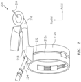
FIG. 2 , an example of anACC system 200 in accordance with the prior art is shown. In thesystem 200,bleed air 204 is taken from, e.g., the compressor and is supplied to one or more manifolds (e.g.,manifolds inlet pipe 216 and acollector 218. Themanifolds bleed air 204 onto the case. A portion of thebleed air 204 may be conveyed to other portions/sections of the engine via piping/tubing 224. - The
interface 232 between thecollector 218 and themanifolds collector 218 relative to themanifolds ACC system 200 may suffer a supply pressure drop that may result in a loss of closure of theACC system 200. -
US 6 126 389 A discloses a prior art insert as set forth in the preamble ofclaim 1. - According to the present invention, there is provided an insert configured to be coupled to a collector of an active clearance control system of an engine of an aircraft as recited in
claim 1. - The present disclosure is illustrated by way of example and not limited in the accompanying figures in which like reference numerals indicate similar elements. The drawings are not necessarily drawn to scale unless specifically indicated otherwise.
-
FIG. 1 is a side cutaway illustration of a geared turbine engine. -
FIG. 2 illustrates a prior art active clearance control (ACC) system. -
FIG. 3 illustrates a portion of an ACC system incorporating an insert in accordance with aspects of this disclosure. -
FIG. 4 illustrates a side perspective view of a portion of the ACC system ofFIG. 3 . -
FIG. 5 illustrates an insert of an ACC system according to the present invention. - It is noted that various connections are set forth between elements in the following description and in the drawings (the contents of which are included in this disclosure by way of reference). It is noted that these connections are general and, unless specified otherwise, may be direct or indirect and that this specification is not intended to be limiting in this respect. A coupling between two or more entities may refer to a direct connection or an indirect connection. An indirect connection may incorporate one or more intervening entities.
- In accordance with aspects of the disclosure, apparatuses, systems, and methods are directed to an insert. The insert includes a flange/gasket coupled to four or more posts/chimneys. A post may be seated within a receptacle formed in a manifold. The insert may seal a leak that might otherwise be present between a collector and the manifold, which may assist in the performance (e.g., closure) of an active clearance control (ACC) system.
- Aspects of the disclosure may be applied in connection with a gas turbine engine.
FIG. 1 is a side cutaway illustration of a gearedturbine engine 10. Thisturbine engine 10 extends along anaxial centerline 12 between anupstream airflow inlet 14 and adownstream airflow exhaust 16. Theturbine engine 10 includes afan section 18, acompressor section 19, acombustor section 20 and aturbine section 21. Thecompressor section 19 includes a low pressure compressor (LPC)section 19A and a high pressure compressor (HPC)section 19B. Theturbine section 21 includes a high pressure turbine (HPT)section 21A and a low pressure turbine (LPT)section 21B. - The engine sections 18-21 are arranged sequentially along the
centerline 12 within anengine housing 22. Each of the engine sections 18-19B, 21A and 21B includes a respective rotor 24-28. Each of these rotors 24-28 includes a plurality of rotor blades arranged circumferentially around and connected to one or more respective rotor disks. The rotor blades, for example, may be formed integral with or mechanically fastened, welded, brazed, adhered and/or otherwise attached to the respective rotor disk(s). - The
fan rotor 24 is connected to agear train 30, for example, through afan shaft 32. Thegear train 30 and theLPC rotor 25 are connected to and driven by theLPT rotor 28 through alow speed shaft 33. TheHPC rotor 26 is connected to and driven by theHPT rotor 27 through ahigh speed shaft 34. The shafts 32-34 are rotatably supported by a plurality ofbearings 36; e.g., rolling element and/or thrust bearings. Each of thesebearings 36 is connected to theengine housing 22 by at least one stationary structure such as, for example, an annular support strut. - During operation, air enters the
turbine engine 10 through theairflow inlet 14, and is directed through thefan section 18 and into acore gas path 38 and abypass gas path 40. The air within thecore gas path 38 may be referred to as "core air". The air within thebypass gas path 40 may be referred to as "bypass air". The core air is directed through the engine sections 19-21, and exits theturbine engine 10 through theairflow exhaust 16 to provide forward engine thrust. Within thecombustor section 20, fuel is injected into acombustion chamber 42 and mixed with compressed core air. This fuel-core air mixture is ignited to power theturbine engine 10. The bypass air is directed through thebypass gas path 40 and out of theturbine engine 10 through abypass nozzle 44 to provide additional forward engine thrust. This additional forward engine thrust may account for a majority (e.g., more than 70 percent) of total engine thrust. Alternatively, at least some of the bypass air may be directed out of theturbine engine 10 through a thrust reverser to provide reverse engine thrust. -
FIG. 1 represents one possible configuration for anengine 10. Aspects of the disclosure may be applied in connection with other environments, including additional configurations for gas turbine engines. Aspects of the disclosure may be applied in connection with non-geared engines. - Referring to
FIG. 3 , a (portion of an)ACC system 300 is shown. Thesystem 300 may be incorporated at part of an engine, such as for example theengine 10 ofFIG. 1 . - The
system 300 may include acollector 318 andmanifolds manifolds collector 318 may be made of one or more materials, such as for example stainless steel. Thecollector 318 may be configured to receive a coolingfluid 304. The coolingfluid 304 may include air received from one or more sections of an engine (e.g.,compressor section 19 ofFIG. 1 ). - Depending on loading, one or more of the
first manifold 312a, thesecond manifold 312b, and thecollector 318 may move/deflect relative to at least one of the others of thefirst manifold 312a, thesecond manifold 312b, and thecollector 318. - To mitigate/prevent the impact of a bleed air leak that might otherwise develop due to the movement/deflection described above, the
system 300 includes aninsert 330 located at the interface between thecollector 318, the manifold 312a, and the manifold 312b. Theinsert 330 may be made of one or more materials. Theinsert 330 includes sheet metal. - The
insert 330 includes a flange/gasket 334 that may terminate at a first end in a first post/chimney 338a and at a second end in a second post/chimney 338b. The first andsecond posts collector 318 and therespective manifold flange 334 includes a foam material, that has a large compression capability (e.g., larger than a threshold) to accommodate the movement/deflection described above. - The
post 338a may be seated in areceptacle 342a formed in the manifold 312a. Thepost 338b may be seated in areceptacle 342b formed in the manifold 312b. - One or more dimensions of the
posts system 300 may experience (which, in turn, may correspond to the amount/degree of movement/deflection that may be experienced over the engine operating range). Referring toFIGS. 3-4 , a (radially-oriented) height HA of thepost 338a may be selected so as to accommodate a (radially-oriented) movement/deflection of thecollector 318 relative to the manifold 312a over the full engine operating range. The height HA may be selected to be at least long enough so as to ensure that thepost 338a is seated in thereceptacle 342a when thecollector 318 experiences maximum (radial) separation from the manifold 312a. Similarly, the height HB of thepost 338b may be selected to be at least long enough so as to ensure that thepost 338b is seated in thereceptacle 342b when thecollector 318 experiences maximum (radial) separation from the manifold 312b. - While the example described above related to the (radially-oriented) heights HA and HB of the
posts posts receptacles - While the
posts receptacles posts 338a/338b and thereceptacles 342a/342 may assume the shape of a rectangle, oval, circle, triangle, etc., and even irregular shapes. - While some of the examples not covered by the claims described herein related to an insert (e.g., insert 330) including two posts (e.g.,
posts FIG. 5 illustrates aninsert 530 according to the present invention that includes aflange 534, apost 538a-1, apost 538a-2, apost 538b-1, and apost 538b-2. Theposts 538a-1 and 538a-2 may be seated in respective receptacles formed in a first manifold and theposts 538b-1 and 538b-2 may be seated in respective receptacles formed in a second manifold. Referring to the geometry/orientation associated withFIGS. 2-4 , theposts 538a-1 and 538a-2 may be substantially located in a first axial plane/station and theposts 538b-1 and 538b-2 may be substantially located in a second axial plane/station that is different from the first axial plane/station. - Technical effects and benefits of this disclosure include an insert that bridges a potential (axial) gap between two or more manifolds. The insert may be coupled to the manifolds and may be coupled to a collector of an ACC system. The insert may accommodate relative movement between at least two of a first of the manifolds, a second of the manifolds, and a collector over an operating range of an engine while ensuring that adequate sealing is provided (e.g., leakage at an interface between the collector and the manifolds may be less than a threshold).
- Aspects of the disclosure have been described in terms of illustrative embodiments thereof. Numerous other embodiments, modifications, and variations within the scope of the appended claims will occur to persons of ordinary skill in the art from a review of this disclosure. For example, one of ordinary skill in the art will appreciate that the steps described in conjunction with the illustrative figures may be performed in other than the recited order, and that one or more steps illustrated may be optional in accordance with aspects of the disclosure. One or more features described in connection with a first embodiment may be combined with one or more features of one or more additional embodiments.
Claims (1)
- An insert (530) configured to be coupled to a collector (318) of an active clearance control system of an engine (10) of an aircraft, the insert (530) comprising:a flange (534);a first post (538a-1) coupled to the flange (534) and configured to be seated in a first receptacle formed in a first manifold where the first post (538a-1) allows a first portion of bleed air in a collector (318) to flow from the collector (318) to the first manifold (312a);a second post (538b-1) coupled to the flange (534) and configured to be seated in a second receptacle formed in the first manifold where the second post (538b-1) allows a second portion of the bleed air in the collector (318) to flow from the collector (318) to the first manifold (312a);a third post (538a-2) coupled to the flange (534) and configured to be seated in a third receptacle formed in a second manifold where the third post (538a-2) allows a third portion of the bleed air in the collector (318) to flow from the collector (318) to the second manifold; anda fourth post (538b-2) coupled to the flange (534) and configured to be seated in a fourth receptacle formed in the second manifold where the fourth post (538b-2) allows a fourth portion of the bleed air in the collector (318) to flow from the collector (318) to the second manifold,characterised in thatthe insert (530) includes sheet metal and the flange (534) includes a foam material.
Applications Claiming Priority (2)
| Application Number | Priority Date | Filing Date | Title |
|---|---|---|---|
| US15/239,899 US10612409B2 (en) | 2016-08-18 | 2016-08-18 | Active clearance control collector to manifold insert |
| EP17186230.3A EP3284917B1 (en) | 2016-08-18 | 2017-08-15 | Active clearance control collector to manifold insert |
Related Parent Applications (2)
| Application Number | Title | Priority Date | Filing Date |
|---|---|---|---|
| EP17186230.3A Division-Into EP3284917B1 (en) | 2016-08-18 | 2017-08-15 | Active clearance control collector to manifold insert |
| EP17186230.3A Division EP3284917B1 (en) | 2016-08-18 | 2017-08-15 | Active clearance control collector to manifold insert |
Publications (2)
| Publication Number | Publication Date |
|---|---|
| EP3757353A1 EP3757353A1 (en) | 2020-12-30 |
| EP3757353B1 true EP3757353B1 (en) | 2023-05-10 |
Family
ID=59631614
Family Applications (2)
| Application Number | Title | Priority Date | Filing Date |
|---|---|---|---|
| EP17186230.3A Active EP3284917B1 (en) | 2016-08-18 | 2017-08-15 | Active clearance control collector to manifold insert |
| EP20186864.3A Active EP3757353B1 (en) | 2016-08-18 | 2017-08-15 | Insert for a collector of an active clearance control system of an engine of an aircraft |
Family Applications Before (1)
| Application Number | Title | Priority Date | Filing Date |
|---|---|---|---|
| EP17186230.3A Active EP3284917B1 (en) | 2016-08-18 | 2017-08-15 | Active clearance control collector to manifold insert |
Country Status (2)
| Country | Link |
|---|---|
| US (1) | US10612409B2 (en) |
| EP (2) | EP3284917B1 (en) |
Families Citing this family (1)
| Publication number | Priority date | Publication date | Assignee | Title |
|---|---|---|---|---|
| EP3995672B1 (en) * | 2020-11-10 | 2025-12-24 | GE Vernova Technology GmbH | Systems and methods for controlling temperature in a supporting foundation used with a gas turbine engine |
Family Cites Families (20)
| Publication number | Priority date | Publication date | Assignee | Title |
|---|---|---|---|---|
| US4131388A (en) | 1977-05-26 | 1978-12-26 | United Technologies Corporation | Outer air seal |
| US5601402A (en) | 1986-06-06 | 1997-02-11 | The United States Of America As Represented By The Secretary Of The Air Force | Turbo machine shroud-to-rotor blade dynamic clearance control |
| US4815272A (en) | 1987-05-05 | 1989-03-28 | United Technologies Corporation | Turbine cooling and thermal control |
| US5281085A (en) | 1990-12-21 | 1994-01-25 | General Electric Company | Clearance control system for separately expanding or contracting individual portions of an annular shroud |
| US5205115A (en) * | 1991-11-04 | 1993-04-27 | General Electric Company | Gas turbine engine case counterflow thermal control |
| US5641267A (en) | 1995-06-06 | 1997-06-24 | General Electric Company | Controlled leakage shroud panel |
| US5791872A (en) | 1997-04-22 | 1998-08-11 | Rolls-Royce Inc. | Blade tip clearence control apparatus |
| FR2766232B1 (en) * | 1997-07-18 | 1999-08-20 | Snecma | CIRCULAR HOUSING COOLING OR HEATING DEVICE |
| US6126389A (en) | 1998-09-02 | 2000-10-03 | General Electric Co. | Impingement cooling for the shroud of a gas turbine |
| US6350102B1 (en) | 2000-07-19 | 2002-02-26 | General Electric Company | Shroud leakage flow discouragers |
| GB2388407B (en) | 2002-05-10 | 2005-10-26 | Rolls Royce Plc | Gas turbine blade tip clearance control structure |
| US6877952B2 (en) | 2002-09-09 | 2005-04-12 | Florida Turbine Technologies, Inc | Passive clearance control |
| FR2858652B1 (en) * | 2003-08-06 | 2006-02-10 | Snecma Moteurs | DEVICE FOR CONTROLLING PLAY IN A GAS TURBINE |
| US7819626B2 (en) | 2006-10-13 | 2010-10-26 | General Electric Company | Plasma blade tip clearance control |
| US8434997B2 (en) | 2007-08-22 | 2013-05-07 | United Technologies Corporation | Gas turbine engine case for clearance control |
| US8152446B2 (en) | 2007-08-23 | 2012-04-10 | General Electric Company | Apparatus and method for reducing eccentricity and out-of-roundness in turbines |
| FR2977276B1 (en) * | 2011-06-30 | 2016-12-09 | Snecma | ARRANGEMENT FOR CONNECTING A DUCT TO AN AIR DISTRIBUTION HOUSING |
| US9039346B2 (en) | 2011-10-17 | 2015-05-26 | General Electric Company | Rotor support thermal control system |
| US8720317B2 (en) | 2011-12-29 | 2014-05-13 | Etagen, Inc. | Methods and systems for managing a clearance gap in a piston engine |
| US9810091B2 (en) | 2014-08-12 | 2017-11-07 | United Technologies Corporation | Smart active clearance control between a rotor blade and a shroud |
-
2016
- 2016-08-18 US US15/239,899 patent/US10612409B2/en active Active
-
2017
- 2017-08-15 EP EP17186230.3A patent/EP3284917B1/en active Active
- 2017-08-15 EP EP20186864.3A patent/EP3757353B1/en active Active
Also Published As
| Publication number | Publication date |
|---|---|
| US20180051583A1 (en) | 2018-02-22 |
| EP3284917B1 (en) | 2020-09-30 |
| EP3757353A1 (en) | 2020-12-30 |
| EP3284917A1 (en) | 2018-02-21 |
| US10612409B2 (en) | 2020-04-07 |
Similar Documents
| Publication | Publication Date | Title |
|---|---|---|
| US10208615B2 (en) | Seal shoe for a hydrostatic non-contact seal device | |
| US6439616B1 (en) | Anti-rotation retainer for a conduit | |
| US20180340615A1 (en) | Shaped spring element for a non-contact seal device | |
| US20120167588A1 (en) | Compressor tip clearance control and gas turbine engine | |
| US10233775B2 (en) | Engine component for a gas turbine engine | |
| US9291061B2 (en) | Turbomachine blade tip shroud with parallel casing configuration | |
| EP3287674B1 (en) | Floating, non-contact seal with offset building clearance for load imbalance | |
| EP3418610B1 (en) | Hydrostatic non-contact seal with weight reduction pocket | |
| US20140311164A1 (en) | Gas turbine engine and turbine blade | |
| EP3290755A1 (en) | Floating, non-contact seal with at least three beams | |
| US8734089B2 (en) | Damper seal and vane assembly for a gas turbine engine | |
| EP3502421A1 (en) | A gas turbine engine triple bend finger seal | |
| US10100648B2 (en) | Damper seal installation features | |
| CN107060897B (en) | Slotted Seals for Gas Turbine Engines | |
| US20180216467A1 (en) | Turbine engine with an extension into a buffer cavity | |
| US20180230856A1 (en) | Engine cases and associated flange | |
| US10502060B2 (en) | Rotor and gas turbine engine including same | |
| EP3284917B1 (en) | Active clearance control collector to manifold insert | |
| EP3203023A1 (en) | Gas turbine engine with a cooling fluid path | |
| US20070297918A1 (en) | Gas turbine engine with contoured air supply slot in turbine rotor | |
| EP3333375A1 (en) | Sync ring assembly and associated clevis including a rib | |
| EP4571192A1 (en) | Fuel spray nozzle for a gas turbine engine | |
| US20090060736A1 (en) | Compressor |
Legal Events
| Date | Code | Title | Description |
|---|---|---|---|
| PUAI | Public reference made under article 153(3) epc to a published international application that has entered the european phase |
Free format text: ORIGINAL CODE: 0009012 |
|
| STAA | Information on the status of an ep patent application or granted ep patent |
Free format text: STATUS: THE APPLICATION HAS BEEN PUBLISHED |
|
| AC | Divisional application: reference to earlier application |
Ref document number: 3284917 Country of ref document: EP Kind code of ref document: P |
|
| AK | Designated contracting states |
Kind code of ref document: A1 Designated state(s): AL AT BE BG CH CY CZ DE DK EE ES FI FR GB GR HR HU IE IS IT LI LT LU LV MC MK MT NL NO PL PT RO RS SE SI SK SM TR |
|
| STAA | Information on the status of an ep patent application or granted ep patent |
Free format text: STATUS: REQUEST FOR EXAMINATION WAS MADE |
|
| 17P | Request for examination filed |
Effective date: 20210629 |
|
| RBV | Designated contracting states (corrected) |
Designated state(s): AL AT BE BG CH CY CZ DE DK EE ES FI FR GB GR HR HU IE IS IT LI LT LU LV MC MK MT NL NO PL PT RO RS SE SI SK SM TR |
|
| GRAP | Despatch of communication of intention to grant a patent |
Free format text: ORIGINAL CODE: EPIDOSNIGR1 |
|
| STAA | Information on the status of an ep patent application or granted ep patent |
Free format text: STATUS: GRANT OF PATENT IS INTENDED |
|
| INTG | Intention to grant announced |
Effective date: 20221130 |
|
| GRAS | Grant fee paid |
Free format text: ORIGINAL CODE: EPIDOSNIGR3 |
|
| GRAA | (expected) grant |
Free format text: ORIGINAL CODE: 0009210 |
|
| STAA | Information on the status of an ep patent application or granted ep patent |
Free format text: STATUS: THE PATENT HAS BEEN GRANTED |
|
| AC | Divisional application: reference to earlier application |
Ref document number: 3284917 Country of ref document: EP Kind code of ref document: P |
|
| AK | Designated contracting states |
Kind code of ref document: B1 Designated state(s): AL AT BE BG CH CY CZ DE DK EE ES FI FR GB GR HR HU IE IS IT LI LT LU LV MC MK MT NL NO PL PT RO RS SE SI SK SM TR |
|
| REG | Reference to a national code |
Ref country code: GB Ref legal event code: FG4D |
|
| REG | Reference to a national code |
Ref country code: AT Ref legal event code: REF Ref document number: 1566872 Country of ref document: AT Kind code of ref document: T Effective date: 20230515 Ref country code: CH Ref legal event code: EP |
|
| REG | Reference to a national code |
Ref country code: DE Ref legal event code: R096 Ref document number: 602017068801 Country of ref document: DE |
|
| REG | Reference to a national code |
Ref country code: IE Ref legal event code: FG4D |
|
| P01 | Opt-out of the competence of the unified patent court (upc) registered |
Effective date: 20230603 |
|
| REG | Reference to a national code |
Ref country code: LT Ref legal event code: MG9D |
|
| REG | Reference to a national code |
Ref country code: NL Ref legal event code: MP Effective date: 20230510 |
|
| REG | Reference to a national code |
Ref country code: AT Ref legal event code: MK05 Ref document number: 1566872 Country of ref document: AT Kind code of ref document: T Effective date: 20230510 |
|
| PG25 | Lapsed in a contracting state [announced via postgrant information from national office to epo] |
Ref country code: SE Free format text: LAPSE BECAUSE OF FAILURE TO SUBMIT A TRANSLATION OF THE DESCRIPTION OR TO PAY THE FEE WITHIN THE PRESCRIBED TIME-LIMIT Effective date: 20230510 Ref country code: PT Free format text: LAPSE BECAUSE OF FAILURE TO SUBMIT A TRANSLATION OF THE DESCRIPTION OR TO PAY THE FEE WITHIN THE PRESCRIBED TIME-LIMIT Effective date: 20230911 Ref country code: NO Free format text: LAPSE BECAUSE OF FAILURE TO SUBMIT A TRANSLATION OF THE DESCRIPTION OR TO PAY THE FEE WITHIN THE PRESCRIBED TIME-LIMIT Effective date: 20230810 Ref country code: NL Free format text: LAPSE BECAUSE OF FAILURE TO SUBMIT A TRANSLATION OF THE DESCRIPTION OR TO PAY THE FEE WITHIN THE PRESCRIBED TIME-LIMIT Effective date: 20230510 Ref country code: ES Free format text: LAPSE BECAUSE OF FAILURE TO SUBMIT A TRANSLATION OF THE DESCRIPTION OR TO PAY THE FEE WITHIN THE PRESCRIBED TIME-LIMIT Effective date: 20230510 Ref country code: AT Free format text: LAPSE BECAUSE OF FAILURE TO SUBMIT A TRANSLATION OF THE DESCRIPTION OR TO PAY THE FEE WITHIN THE PRESCRIBED TIME-LIMIT Effective date: 20230510 |
|
| RAP4 | Party data changed (patent owner data changed or rights of a patent transferred) |
Owner name: RTX CORPORATION |
|
| PG25 | Lapsed in a contracting state [announced via postgrant information from national office to epo] |
Ref country code: RS Free format text: LAPSE BECAUSE OF FAILURE TO SUBMIT A TRANSLATION OF THE DESCRIPTION OR TO PAY THE FEE WITHIN THE PRESCRIBED TIME-LIMIT Effective date: 20230510 Ref country code: PL Free format text: LAPSE BECAUSE OF FAILURE TO SUBMIT A TRANSLATION OF THE DESCRIPTION OR TO PAY THE FEE WITHIN THE PRESCRIBED TIME-LIMIT Effective date: 20230510 Ref country code: LV Free format text: LAPSE BECAUSE OF FAILURE TO SUBMIT A TRANSLATION OF THE DESCRIPTION OR TO PAY THE FEE WITHIN THE PRESCRIBED TIME-LIMIT Effective date: 20230510 Ref country code: LT Free format text: LAPSE BECAUSE OF FAILURE TO SUBMIT A TRANSLATION OF THE DESCRIPTION OR TO PAY THE FEE WITHIN THE PRESCRIBED TIME-LIMIT Effective date: 20230510 Ref country code: IS Free format text: LAPSE BECAUSE OF FAILURE TO SUBMIT A TRANSLATION OF THE DESCRIPTION OR TO PAY THE FEE WITHIN THE PRESCRIBED TIME-LIMIT Effective date: 20230910 Ref country code: HR Free format text: LAPSE BECAUSE OF FAILURE TO SUBMIT A TRANSLATION OF THE DESCRIPTION OR TO PAY THE FEE WITHIN THE PRESCRIBED TIME-LIMIT Effective date: 20230510 Ref country code: GR Free format text: LAPSE BECAUSE OF FAILURE TO SUBMIT A TRANSLATION OF THE DESCRIPTION OR TO PAY THE FEE WITHIN THE PRESCRIBED TIME-LIMIT Effective date: 20230811 |
|
| PG25 | Lapsed in a contracting state [announced via postgrant information from national office to epo] |
Ref country code: FI Free format text: LAPSE BECAUSE OF FAILURE TO SUBMIT A TRANSLATION OF THE DESCRIPTION OR TO PAY THE FEE WITHIN THE PRESCRIBED TIME-LIMIT Effective date: 20230510 |
|
| PG25 | Lapsed in a contracting state [announced via postgrant information from national office to epo] |
Ref country code: SK Free format text: LAPSE BECAUSE OF FAILURE TO SUBMIT A TRANSLATION OF THE DESCRIPTION OR TO PAY THE FEE WITHIN THE PRESCRIBED TIME-LIMIT Effective date: 20230510 |
|
| PG25 | Lapsed in a contracting state [announced via postgrant information from national office to epo] |
Ref country code: SM Free format text: LAPSE BECAUSE OF FAILURE TO SUBMIT A TRANSLATION OF THE DESCRIPTION OR TO PAY THE FEE WITHIN THE PRESCRIBED TIME-LIMIT Effective date: 20230510 Ref country code: SK Free format text: LAPSE BECAUSE OF FAILURE TO SUBMIT A TRANSLATION OF THE DESCRIPTION OR TO PAY THE FEE WITHIN THE PRESCRIBED TIME-LIMIT Effective date: 20230510 Ref country code: RO Free format text: LAPSE BECAUSE OF FAILURE TO SUBMIT A TRANSLATION OF THE DESCRIPTION OR TO PAY THE FEE WITHIN THE PRESCRIBED TIME-LIMIT Effective date: 20230510 Ref country code: EE Free format text: LAPSE BECAUSE OF FAILURE TO SUBMIT A TRANSLATION OF THE DESCRIPTION OR TO PAY THE FEE WITHIN THE PRESCRIBED TIME-LIMIT Effective date: 20230510 Ref country code: DK Free format text: LAPSE BECAUSE OF FAILURE TO SUBMIT A TRANSLATION OF THE DESCRIPTION OR TO PAY THE FEE WITHIN THE PRESCRIBED TIME-LIMIT Effective date: 20230510 Ref country code: CZ Free format text: LAPSE BECAUSE OF FAILURE TO SUBMIT A TRANSLATION OF THE DESCRIPTION OR TO PAY THE FEE WITHIN THE PRESCRIBED TIME-LIMIT Effective date: 20230510 |
|
| REG | Reference to a national code |
Ref country code: DE Ref legal event code: R097 Ref document number: 602017068801 Country of ref document: DE |
|
| PG25 | Lapsed in a contracting state [announced via postgrant information from national office to epo] |
Ref country code: MC Free format text: LAPSE BECAUSE OF FAILURE TO SUBMIT A TRANSLATION OF THE DESCRIPTION OR TO PAY THE FEE WITHIN THE PRESCRIBED TIME-LIMIT Effective date: 20230510 |
|
| PLBE | No opposition filed within time limit |
Free format text: ORIGINAL CODE: 0009261 |
|
| STAA | Information on the status of an ep patent application or granted ep patent |
Free format text: STATUS: NO OPPOSITION FILED WITHIN TIME LIMIT |
|
| REG | Reference to a national code |
Ref country code: CH Ref legal event code: PL |
|
| PG25 | Lapsed in a contracting state [announced via postgrant information from national office to epo] |
Ref country code: MC Free format text: LAPSE BECAUSE OF FAILURE TO SUBMIT A TRANSLATION OF THE DESCRIPTION OR TO PAY THE FEE WITHIN THE PRESCRIBED TIME-LIMIT Effective date: 20230510 |
|
| PG25 | Lapsed in a contracting state [announced via postgrant information from national office to epo] |
Ref country code: LU Free format text: LAPSE BECAUSE OF NON-PAYMENT OF DUE FEES Effective date: 20230815 |
|
| 26N | No opposition filed |
Effective date: 20240213 |
|
| PG25 | Lapsed in a contracting state [announced via postgrant information from national office to epo] |
Ref country code: LU Free format text: LAPSE BECAUSE OF NON-PAYMENT OF DUE FEES Effective date: 20230815 Ref country code: CH Free format text: LAPSE BECAUSE OF NON-PAYMENT OF DUE FEES Effective date: 20230831 |
|
| PG25 | Lapsed in a contracting state [announced via postgrant information from national office to epo] |
Ref country code: SI Free format text: LAPSE BECAUSE OF FAILURE TO SUBMIT A TRANSLATION OF THE DESCRIPTION OR TO PAY THE FEE WITHIN THE PRESCRIBED TIME-LIMIT Effective date: 20230510 |
|
| REG | Reference to a national code |
Ref country code: BE Ref legal event code: MM Effective date: 20230831 |
|
| REG | Reference to a national code |
Ref country code: IE Ref legal event code: MM4A |
|
| PG25 | Lapsed in a contracting state [announced via postgrant information from national office to epo] |
Ref country code: SI Free format text: LAPSE BECAUSE OF FAILURE TO SUBMIT A TRANSLATION OF THE DESCRIPTION OR TO PAY THE FEE WITHIN THE PRESCRIBED TIME-LIMIT Effective date: 20230510 Ref country code: IT Free format text: LAPSE BECAUSE OF FAILURE TO SUBMIT A TRANSLATION OF THE DESCRIPTION OR TO PAY THE FEE WITHIN THE PRESCRIBED TIME-LIMIT Effective date: 20230510 |
|
| PG25 | Lapsed in a contracting state [announced via postgrant information from national office to epo] |
Ref country code: IE Free format text: LAPSE BECAUSE OF NON-PAYMENT OF DUE FEES Effective date: 20230815 |
|
| PG25 | Lapsed in a contracting state [announced via postgrant information from national office to epo] |
Ref country code: IE Free format text: LAPSE BECAUSE OF NON-PAYMENT OF DUE FEES Effective date: 20230815 |
|
| PG25 | Lapsed in a contracting state [announced via postgrant information from national office to epo] |
Ref country code: BE Free format text: LAPSE BECAUSE OF NON-PAYMENT OF DUE FEES Effective date: 20230831 |
|
| PG25 | Lapsed in a contracting state [announced via postgrant information from national office to epo] |
Ref country code: BG Free format text: LAPSE BECAUSE OF FAILURE TO SUBMIT A TRANSLATION OF THE DESCRIPTION OR TO PAY THE FEE WITHIN THE PRESCRIBED TIME-LIMIT Effective date: 20230510 |
|
| PG25 | Lapsed in a contracting state [announced via postgrant information from national office to epo] |
Ref country code: BG Free format text: LAPSE BECAUSE OF FAILURE TO SUBMIT A TRANSLATION OF THE DESCRIPTION OR TO PAY THE FEE WITHIN THE PRESCRIBED TIME-LIMIT Effective date: 20230510 |
|
| PG25 | Lapsed in a contracting state [announced via postgrant information from national office to epo] |
Ref country code: CY Free format text: LAPSE BECAUSE OF FAILURE TO SUBMIT A TRANSLATION OF THE DESCRIPTION OR TO PAY THE FEE WITHIN THE PRESCRIBED TIME-LIMIT; INVALID AB INITIO Effective date: 20170815 |
|
| PG25 | Lapsed in a contracting state [announced via postgrant information from national office to epo] |
Ref country code: HU Free format text: LAPSE BECAUSE OF FAILURE TO SUBMIT A TRANSLATION OF THE DESCRIPTION OR TO PAY THE FEE WITHIN THE PRESCRIBED TIME-LIMIT; INVALID AB INITIO Effective date: 20170815 |
|
| REG | Reference to a national code |
Ref country code: DE Ref legal event code: R081 Ref document number: 602017068801 Country of ref document: DE Owner name: RTX CORPORATION (N.D.GES.D. STAATES DELAWARE),, US Free format text: FORMER OWNER: RAYTHEON TECHNOLOGIES CORPORATION, FARMINGTON, CT, US |
|
| PGFP | Annual fee paid to national office [announced via postgrant information from national office to epo] |
Ref country code: DE Payment date: 20250724 Year of fee payment: 9 |
|
| PGFP | Annual fee paid to national office [announced via postgrant information from national office to epo] |
Ref country code: GB Payment date: 20250724 Year of fee payment: 9 |
|
| PGFP | Annual fee paid to national office [announced via postgrant information from national office to epo] |
Ref country code: FR Payment date: 20250723 Year of fee payment: 9 |
|
| PG25 | Lapsed in a contracting state [announced via postgrant information from national office to epo] |
Ref country code: TR Free format text: LAPSE BECAUSE OF FAILURE TO SUBMIT A TRANSLATION OF THE DESCRIPTION OR TO PAY THE FEE WITHIN THE PRESCRIBED TIME-LIMIT Effective date: 20230510 |