EP3757256A1 - Electrodeposited copper foil - Google Patents
Electrodeposited copper foil Download PDFInfo
- Publication number
- EP3757256A1 EP3757256A1 EP20181805.1A EP20181805A EP3757256A1 EP 3757256 A1 EP3757256 A1 EP 3757256A1 EP 20181805 A EP20181805 A EP 20181805A EP 3757256 A1 EP3757256 A1 EP 3757256A1
- Authority
- EP
- European Patent Office
- Prior art keywords
- copper foil
- electrodeposited copper
- ppm
- rδq
- lithium
- Prior art date
- Legal status (The legal status is an assumption and is not a legal conclusion. Google has not performed a legal analysis and makes no representation as to the accuracy of the status listed.)
- Granted
Links
Images


Classifications
-
- C—CHEMISTRY; METALLURGY
- C25—ELECTROLYTIC OR ELECTROPHORETIC PROCESSES; APPARATUS THEREFOR
- C25D—PROCESSES FOR THE ELECTROLYTIC OR ELECTROPHORETIC PRODUCTION OF COATINGS; ELECTROFORMING; APPARATUS THEREFOR
- C25D1/00—Electroforming
- C25D1/04—Wires; Strips; Foils
-
- C—CHEMISTRY; METALLURGY
- C25—ELECTROLYTIC OR ELECTROPHORETIC PROCESSES; APPARATUS THEREFOR
- C25D—PROCESSES FOR THE ELECTROLYTIC OR ELECTROPHORETIC PRODUCTION OF COATINGS; ELECTROFORMING; APPARATUS THEREFOR
- C25D1/00—Electroforming
-
- C—CHEMISTRY; METALLURGY
- C25—ELECTROLYTIC OR ELECTROPHORETIC PROCESSES; APPARATUS THEREFOR
- C25D—PROCESSES FOR THE ELECTROLYTIC OR ELECTROPHORETIC PRODUCTION OF COATINGS; ELECTROFORMING; APPARATUS THEREFOR
- C25D3/00—Electroplating: Baths therefor
- C25D3/02—Electroplating: Baths therefor from solutions
- C25D3/38—Electroplating: Baths therefor from solutions of copper
-
- C—CHEMISTRY; METALLURGY
- C25—ELECTROLYTIC OR ELECTROPHORETIC PROCESSES; APPARATUS THEREFOR
- C25D—PROCESSES FOR THE ELECTROLYTIC OR ELECTROPHORETIC PRODUCTION OF COATINGS; ELECTROFORMING; APPARATUS THEREFOR
- C25D7/00—Electroplating characterised by the article coated
- C25D7/06—Wires; Strips; Foils
- C25D7/0614—Strips or foils
-
- H—ELECTRICITY
- H01—ELECTRIC ELEMENTS
- H01M—PROCESSES OR MEANS, e.g. BATTERIES, FOR THE DIRECT CONVERSION OF CHEMICAL ENERGY INTO ELECTRICAL ENERGY
- H01M10/00—Secondary cells; Manufacture thereof
- H01M10/05—Accumulators with non-aqueous electrolyte
- H01M10/052—Li-accumulators
- H01M10/0525—Rocking-chair batteries, i.e. batteries with lithium insertion or intercalation in both electrodes; Lithium-ion batteries
-
- H—ELECTRICITY
- H01—ELECTRIC ELEMENTS
- H01M—PROCESSES OR MEANS, e.g. BATTERIES, FOR THE DIRECT CONVERSION OF CHEMICAL ENERGY INTO ELECTRICAL ENERGY
- H01M4/00—Electrodes
- H01M4/02—Electrodes composed of, or comprising, active material
- H01M4/64—Carriers or collectors
- H01M4/66—Selection of materials
- H01M4/661—Metal or alloys, e.g. alloy coatings
-
- H—ELECTRICITY
- H01—ELECTRIC ELEMENTS
- H01M—PROCESSES OR MEANS, e.g. BATTERIES, FOR THE DIRECT CONVERSION OF CHEMICAL ENERGY INTO ELECTRICAL ENERGY
- H01M10/00—Secondary cells; Manufacture thereof
- H01M10/05—Accumulators with non-aqueous electrolyte
- H01M10/052—Li-accumulators
-
- Y—GENERAL TAGGING OF NEW TECHNOLOGICAL DEVELOPMENTS; GENERAL TAGGING OF CROSS-SECTIONAL TECHNOLOGIES SPANNING OVER SEVERAL SECTIONS OF THE IPC; TECHNICAL SUBJECTS COVERED BY FORMER USPC CROSS-REFERENCE ART COLLECTIONS [XRACs] AND DIGESTS
- Y02—TECHNOLOGIES OR APPLICATIONS FOR MITIGATION OR ADAPTATION AGAINST CLIMATE CHANGE
- Y02E—REDUCTION OF GREENHOUSE GAS [GHG] EMISSIONS, RELATED TO ENERGY GENERATION, TRANSMISSION OR DISTRIBUTION
- Y02E60/00—Enabling technologies; Technologies with a potential or indirect contribution to GHG emissions mitigation
- Y02E60/10—Energy storage using batteries
-
- Y—GENERAL TAGGING OF NEW TECHNOLOGICAL DEVELOPMENTS; GENERAL TAGGING OF CROSS-SECTIONAL TECHNOLOGIES SPANNING OVER SEVERAL SECTIONS OF THE IPC; TECHNICAL SUBJECTS COVERED BY FORMER USPC CROSS-REFERENCE ART COLLECTIONS [XRACs] AND DIGESTS
- Y10—TECHNICAL SUBJECTS COVERED BY FORMER USPC
- Y10T—TECHNICAL SUBJECTS COVERED BY FORMER US CLASSIFICATION
- Y10T428/00—Stock material or miscellaneous articles
- Y10T428/12—All metal or with adjacent metals
- Y10T428/12431—Foil or filament smaller than 6 mils
-
- Y—GENERAL TAGGING OF NEW TECHNOLOGICAL DEVELOPMENTS; GENERAL TAGGING OF CROSS-SECTIONAL TECHNOLOGIES SPANNING OVER SEVERAL SECTIONS OF THE IPC; TECHNICAL SUBJECTS COVERED BY FORMER USPC CROSS-REFERENCE ART COLLECTIONS [XRACs] AND DIGESTS
- Y10—TECHNICAL SUBJECTS COVERED BY FORMER USPC
- Y10T—TECHNICAL SUBJECTS COVERED BY FORMER US CLASSIFICATION
- Y10T428/00—Stock material or miscellaneous articles
- Y10T428/12—All metal or with adjacent metals
- Y10T428/12431—Foil or filament smaller than 6 mils
- Y10T428/12438—Composite
Definitions
- the present disclosure relates to electrodeposited copper foils having high durability and workability.
- the disclosure also relates to lithium ion secondary batteries made using said electrodeposited copper foils.
- Lithium-ion secondary batteries have a combination of high energy and high power density, making it the technology of choice for portable electronic devices, power tools, electric vehicles (“EVs”), energy storage systems (“ESS”), cell phones, tablets, space applications, military applications, and railways.
- Electric vehicles include hybrid electric vehicles (“HEVs”), plug-in hybrid electric vehicles (“PHEVs”), and pure battery electric vehicles (“BEVs”).
- HEVs hybrid electric vehicles
- PHEVs plug-in hybrid electric vehicles
- BEVs pure battery electric vehicles
- lithium-ion secondary batteries are of intense interest for commercial ventures as well as in basic research in government and academic laboratories. Although research and development in this field has abounded in recent years and lithium-ion secondary batteries are currently in use, there remains a need for improvements with respect to higher capacity, higher current generation, and batteries that can undergo more charge/discharge cycles thereby extending their useful life. Additionally, improvements in the weight of the batteries are needed to improve applications in several environments, such as vehicle, portable electronics and space applications.
- Secondary lithium-ion batteries typically include a current collector of a metal foil on which is deposited an active material. Copper foils are often used as the current collector because copper is a good conductor of electrical current. As demands for lower weight batteries become ever more urgent, the current collector needs to be thinner to reduce the size and weight of lithium-ion secondary battery. Additionally, to increase the capacity of the lithium-ion secondary battery, materials such as silicon (Si), germanium (Ge), and tin (Sn) are mixed with or fill the higher capacity active material in a battery, exacerbating the expansion and contraction of the active material and stresses on the copper foil it is in contact with. Furthermore, in some recent advancements, in order to increase the capacity of the batteries, the copper foils, worked as electrodes, are folded or bent and wound. If the copper foil cannot withstand the expansion and contraction of the active material during battery use, or cannot withstand folding and winding during production of the battery, the cycle characteristics of the battery are adversely affected.
- the inventions described herein relate to a copper foil such as electrodeposited copper foils that can be used as a current collector in lithium-ion secondary batteries.
- Copper foils have been prepared having excellent properties improving the workability and durability.
- the copper foils have controlled surface properties such as a controlled surface roughness, which when made into batteries, have extended cycle life.
- improvements have been found by controlling the hydrogen content in the copper foils.
- the invention comprises an electrodeposited copper foil comprising a drum side and a deposited side, wherein at least one of the deposited side and the drum side has a surface roughness characterized by a root mean square slope (R ⁇ q) in the range of about 0.03 to about 0.23, or an R ⁇ q in a range of about 0.03 to about 0.19.
- R ⁇ q root mean square slope
- each of the deposited side and the drum side of the electrodeposited copper foil has an R ⁇ q in the range of about 0.03 to about 0.23.
- the hydrogen content of the electrodeposited copper foil is less than about 50 parts per million (ppm).
- the hydrogen content is in the range of about 10 ppm to about 47 ppm.
- the hydrogen content is in the range of about 10 ppm to about 40 ppm.
- the electrodeposited copper foil is an electrodeposited copper foil further comprising a tarnish resistant layer formed on its exterior so as to have a tarnish resistant formed exterior.
- the tarnish resistant layer is one metal selected from the group consisting of zinc, chromium, nickel, cobalt, molybdenum, vanadium, their alloys and combinations thereof; or an organic tarnish resistant layer.
- the electrodeposited copper foil has a fatigue life/thickness in the range of about 10 ⁇ m -1 to about 36 ⁇ m -1 .
- the electrodeposited copper foil has a tensile strength in a range of about 25 to 75 kg/mm 2 .
- the electrodeposited copper foil has an elongation in a range of about 2 to 35 %.
- the electrodeposited copper foil has a thickness in the range of about 2 ⁇ m to about 25 ⁇ m.
- the electrodeposited copper foil includes substantially no roughing treatment layer.
- the invention comprises a current collector for a lithium-ion secondary battery comprising the electrodeposited copper foil, for example, as describe in the first aspect of the invention.
- the invention comprises a lithium-ion battery comprising the current collector, for example, as describe in the second aspect of the invention.
- each of the deposited side and the drum side of the electrodeposited copper foil has a root mean square slopes (R ⁇ q) in the range of about 0.03 to about 0.23.
- the electrodeposited copper foil as described herein show excellent properties when used in lithium-ion secondary batteries.
- batteries made with these electrodeposited copper foils have excellent charge/discharge cycling properties.
- the copper foils and the active materials do not separate or fracture during high amounts of charge/discharge cycling for the lithium-ion secondary battery. Without being bound to a specific mechanism it is suggested that at least part of these improvements are due to the excellent adhesion between the copper foil and the active material, as well as having reduced number of breaking/failure points in the copper foil.
- Articles of manufacture herein relate to electrodeposited copper foils that have quantifiable characteristics and which provide good performance when used as current collectors.
- these electrodeposited copper foils can be combined with active materials to provide anodes for lithium-ion secondary batteries.
- the embodiments of the electrodeposited copper foils have a surface roughness in a specified range where R ⁇ q is between about 0.03 and 0.23.
- Some embodiments of the electrodeposited copper foils have hydrogen content less than about 50 ppm.
- the electrodeposited copper foil has surface texture or features that affect its properties and final performance when incorporated into a battery.
- One such feature is the surface roughness which can be quantified by the "root mean square slope" (R ⁇ q).
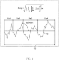
- FIG. 1 shows a plot of surface topography 10, represented by vertical position function Z(x).
- R ⁇ q indicates the root mean square of the local tilt dZ/dX along the sampling length ( l ) 12.
- a high R ⁇ q indicates a higher slope to surface undulation, while a lower R ⁇ q indicates a lower slope to surface undulation.
- the electrodeposited copper foil also has possible variations that affect its properties and also its performance when the copper foil is incorporated into a battery.
- the amount of hydrogen in the copper foil can affect the crystallization of copper and physical properties of the electrodeposited copper foil. Therefore, in some embodiments the hydrogen content of the electrodeposited copper foil is controlled.
- the hydrogen content of the copper foil is higher than 50 ppm, wrinkles and cracks can more easily form on the copper foils during charge and discharge than when the hydrogen content is less than about 50 ppm. Therefore, in some embodiments the hydrogen content is suppressed or kept low, such as lower than about 50 ppm (e.g., between about 10 ppm to about 47 ppm or between about 10 ppm and about 40 ppm). This improves the workability and durability of the electrodeposited copper foil.
- the "drum side” of the copper foil is the surface of the copper foil that is in contact with a drum used during the electrodeposition, while the “deposited side” is the opposite side, or the surface of the electrodeposited copper foil that is in contact with an electrolyte solution during the electrodeposition forming the copper foil.
- These terms relate to a manufacturing process for producing electrodeposited copper foils which include partially immersing a rotating drum assembly into an electrolyte solution containing copper ions. Therefore, under operation of an electric current, copper ions are drawn to the drum and reduced, resulting in copper metal plating onto the surface of the drum forming an electrodeposited copper foil on the surface of the drum.
- This copper foil so formed is removed from the drum in a continuous process by rotating the drum and removing the copper foil as the formed copper foil rotates with the drum out of the electrolyte solution.
- the copper foil can be pulled off the drum as it is formed by, and passed over or through rollers in a continuous process.
- the surface roughness, R ⁇ q, of the electrodeposited copper foil is chosen to be between about 0.03 and 0.23.
- the surface roughness, as represented by R ⁇ q of the electrodeposited copper foil can affect the electrodeposited copper foil in the following manner.
- R ⁇ q is high, for example higher than about 0.23, the number of potential breaking or fracturing points can increase in the copper foil. This results in a more fragile copper foil that can break more easily than an electrodeposited copper foil with R ⁇ q less than about 0.23.
- a higher R ⁇ q correlates with steeper valleys and indentations on the surface of the electrodeposited copper foil, so that the space of the valleys may become narrower. Consequently, with an R ⁇ q of greater than about 0.23, the active material, which can be applied as a viscose slurry or paste to the surface of the electrodeposited copper foil in forming an electrode, does not penetrate deeply into the valleys of the copper foil. That is, a higher R ⁇ q correlates with steeper valleys and the high surface tension of the depositing active material prevents the active material reaching to the bottom of the valleys and reduces the active materials overall intimate contact with the surface of the copper foil. This reduces the adherence of the active material to the surface.
- the amount of potential break points decreases.
- the coating can also be more efficient or uniform in that more contact between the active material and the electrodeposited copper foil occurs.
- too low surface roughness such as where R ⁇ q is less than 0.03, the adhesion between the active material and the surface decreases and detachment, separation, and delamination of the active material from the electrodeposited copper foil can occur.
- too high (R ⁇ q >0.23) or too low (R ⁇ q ⁇ 0.03) surface roughness is therefore that the workability, ductility and durability of the electrodeposited copper foil and electrode formed therefrom is inferior.
- R ⁇ q of the electrodeposited copper foil can be controlled by the surface parameters of the drum.
- the grain size, the grain size distribution, and number of grain boundaries at the drum surface can in some embodiments be used to modulate the R ⁇ q.
- Drums can readily be made having controlled grain size, grain size distributions and densities of grains, and therefore, this allows the control of the R ⁇ q on the drum side of the electrodeposited copper foil.
- the grain density can be quantified by the "grain size number" where a higher number corresponds to a higher grain density while a lower number corresponds to a lower grain density.
- the grain size number can be determined by using standard test method JIS G0552.
- R ⁇ q of the electrodeposited copper foil can be controlled by the composition of the electrolyte used during the deposition process.
- some of the electrolyte components that can affect R ⁇ q include sulfuric acid, chloride ion, accelerator, suppressor, and combinations of these.
- the electrodeposited copper foil includes substantially no roughing treatment layer, and the roughing treatment layer refers to a blackening treatment layer and a nodule layer.
- FIG. 2 shows the unassembled components of a laminated type lithium-ion battery that can incorporate the electrodeposited copper foil as described in the embodiments.
- Laminated type lithium-ion secondary batteries can be made by providing an anode slurry composed of active material, conductive additive, binder, and solvent, and then mixing the slurry and coating it on the surface of the electrodeposited copper foil described herein.
- the coating can be a continuous or an intermittent coating, depending on processing demands.
- the slurry coated electrodeposited copper foil is subsequently heated (e.g., 160°C) in an oven. From the oven, the copper foil is pressed between opposed rollers and then finally cut into sheets which can be used to make a laminated battery.
- the copper foil is made into a current collector of the anode.
- the battery includes a pouch 210 that holds the components of the battery.
- the anode 212 includes an electrodeposited copper foil in contact with an active material on both the drum side and the deposition side of the copper foil.
- the battery also includes a separator 214 and a cathode 216.
- the battery is constructed in a stacked fashion as shown, with the anode 212 contacting the separator 214 on one side of the separator, and the cathode 216 contacting the separator 214 on an opposite side thereof.
- the laminate comprising the anode 212, separator 214 and cathode 216 is contained within the pouch 210.
- the anode 212 is provided with an anode tab 220 that serves as a terminal for the secondary battery.
- the cathode 216 is provided with a cathode tab 222 that serves as another terminal for the secondary battery.
- FIG. 3 shows unassembled components with a partial cutout to illustrate a coin type lithium-ion secondary battery.
- the battery includes a cylindrical cell can 310 that contains additional components of the battery.
- the top of the cylindrical cell can 310 is open and capped with an anode cap 312.
- a cylindrical cathode 314 is placed in the cylindrical cell can 310.
- a separator 316 is placed over the cathode 314.
- Anode 318 is placed over the separator 316.
- the anode cap 312 is compressed against a gasket 320 which compresses against the cathode 314, ensuring electrical isolation of the cathode 314 and anode 318.
- the copper foil is made into a current collector of the cathode 314.
- the electrode made using the copper foil can be formed as a cathode, and the active material coated thereon is a cathode material. In some other embodiments, the electrode made using the copper foil can be formed as an anode, and the active material coated thereon is an anode material.
- the "tensile strength" of a material is the maximum amount of tensile stress that it can be subjected to before failure.
- the "elongation” of a material refers to the maximum amount of elongation that a material can be subjected to before failure.
- the electrodeposited copper foil has a tensile strength in a range of about 25 to 75 kg/mm 2 .
- the electrodeposited copper foil has an elongation in a range of about 2 to 35 %.
- a standard test method that can be used for measuring both the tensile strength and elongation is documented in Standard Test Method IPC-TM-650 2.4.18. For example, testing can be done using a universal testing machine such as is available from Model AG-I testing machine manufactured by Shimadzu Corporation.
- anti-tarnish coating is a coating applied to a metal that can protect the coated metal from degradation such as due to corrosion.
- the electrodeposited copper foil includes an anti-tarnish coating formed on its surfaces so that it has an anti-tarnish formed exterior. This can be made by any known method and includes dipping or passing the formed electrodeposited sheet through a solution containing anti-tarnish forming additives, or electroplating a metal or alloy film on the formed electrodeposited sheet. For example, a bath including any one or more of zinc, chromium, nickel, cobalt, molybdenum, vanadium and combinations thereof; or an organic compound that forms an anti-tarnish resistant layer.
- the processing can be continuous and part of the overall process in preparing the electrodeposited copper foil.
- Charge-discharge testing refers to testing where a potential is applied across the anode and cathode of a battery so as to charge the battery, and then connecting the cathode and anode across a load and allowing the current to pass through the load to discharge the battery. This charge and discharge represents one charge-discharge cycle.
- the testing can be done to simulate how well a battery performs with respect to repeated use.
- the "cycle-life” or “charge-discharge cycle life” is defined as the number of charge-discharge cycles a battery can perform before its nominal capacity falls below 80% of its initial rated capacity.
- An electrodeposited copper foil was prepared by the processes depicted in FIG. 4 showing the formation of copper foil 400 from an electrolyte supplied by an electrolyte source 402 using the drum assembly 404.
- the electrodeposited copper foil 400 was electrodeposited on a rotating drum 412, partially immersed in an electrolyte 430, that is provided through a fluid connection 414 from the electrolyte source 402. Under the influence of an electric current between the anode 416 and the drum 412, where the drum 412 acted as a cathode, the copper ions contained in the electrolyte 430 are reduced and deposited on the surface of the rotating drum 412.
- the copper foil is removed from the drum 412 and fed through guide rollers 450.
- the resulting copper foil 400 was further processed through an anti-tarnish applicator 418, thinned via an air knife 420 and was collected on a copper foil winding spool 422.
- Drums 412 were selected having a grain size number (JIS G 0551-2013) between 7 and 9 for the experiments, and also included some drums having grain size numbers below 7 and above 9 for some of the control experiments.
- the electrolyte was made by dissolving copper wire in an aqueous solution of sulfuric acid (50 wt%) to prepare the copper sulfate electrolyte solution which contained 280 g/L of copper sulfate (CuSO 4 ⁇ 5H 2 O).
- the final sulfuric acid was controlled to several values to make several test solutions in the range of 40-60 g/L of sulfuric acid. Some control test solutions with less than 40 g/L sulfuric acid and higher than 60 g/L of sulfuric acid were also used.
- Hydrochloric acid (RCI Labscan Ltd) was added to provide a chloride ion concentration in the range of 15-25 mg/L for several electrolyte test solutions.
- Some control test solution with less than 15 mg/L of chloride ion and more than 25 mg/L chloride ion were also prepared. Additional components include 3.7 mg/L of chitosan (Chitosan, MW 5000, Sigma-Aldrich, MO) as suppressor and 2.1 mg/L of 3,3'-Thiobis-1-propanesulfonic acid, disodium salt (TBPS), Sigma-Aldrich, MO) as accelerant.
- TBPS 3,3'-Thiobis-1-propanesulfonic acid, disodium salt (TBPS), Sigma-Aldrich, MO
- the depositing conditions of the liquid temperature of the copper sulfate electrolyte was about 43°C, and the current density was about 55 A/dm 2 .
- the surface of copper foil was treated with an anti-corrosion material, in a continuous fashion by guide rollers passing the copper foil through the anti-tarnish applicator 418 containing an anti-tarnish plating bath.
- the anti-tarnish plating bath contained 1.5 g of CrO 3 per liter (obtained from Sigma-Aldrich), at 25° C and the current density was about 0.5 A/dm 2 .
- the plating time is 2 seconds.
- Laminated type lithium-ion secondary batteries were prepared as follows and subjected to high c-rate charging/discharging testing.
- the copper foil is used as the current collector of anode.
- a cathode slurry and an anode slurry were made using N-methyl-2-pyrrolidone (NMP) as solvent.
- NMP N-methyl-2-pyrrolidone
- the cathode slurry was formulated to have a liquid to solid ratio of 195 wt% (195 g of NMP: 100 g of the cathode material).
- the anode slurry was made to have a liquid to solid ratio of 60 wt % (60 g of NMP: 100 g of the anode material).
- Cathode material and Anode material ingredients are shown in Table 1.
- Cathode material formulation Based on the total weight of the cathode material Cathode active substance (LiCoO 2 ) 89 wt% Conductive additive (Flaked graphite; KS6) 5 wt% Conductive additive (Conductive carbon powder; Super P®) 1 wt% Solvent-Based Binder (PVDF1300) 5 wt% Anode material formulation: Based on the total weight of the anode material Anode active substance: Mesophase Graphite Powder (MGPA) 93.9 wt% Conductive additive (Conductive carbon powder; Super P®) 1 wt% Solvent-Based Binder (PVDF6020) 5 wt% Oxalic acid 0.10wt%
- the cathode slurry was coated on aluminum foil, and the anode slurry was coated on the copper foil. After the solvent evaporated, the anode and cathode were pressed and cut into the desired dimensions.
- the cathodes and anodes are alternately stacked with a separator (Celgard Company) sandwiched there between, and placed in a container molded by laminate film.
- the container was filled with an electrolyte (LBC322-01H, manufactured by Shenzhen Capchem Technology Co., Ltd.), and sealed to form a battery.
- the size of the laminated type battery was 41 mm ⁇ 34 mm ⁇ 53 mm.
- the charging mode was a constant current-constant voltage (CCCV) mode, where the charging voltage was 4.2V, and the charging current was 5C.
- C is the C-Rate and refers to the rate at which a battery is charged or discharged relative to its maximum capacity.
- the discharging mode was the constant current (CC) mode, the discharging voltage was 2.8 V, and the discharging current was 5C.
- the charging-discharging test on the batteries was conducted at high temperature (at 55° C).
- Table 2 shows a designed experiment exemplifying embodiments with two surfaces, deposition side and drum side, of an electrodeposited copper foil coated with an active material.
- the design explores the effects of control variable on properties of an electrodeposited copper foil, and on the properties of charge discharge on a laminated type battery.
- the table shows in columns from left to right controlled parameters of Grain size number of the Titanium drum surface, the sulfuric acid concentration (g/L), chloride concentration (ppm), Area weight (g/m 2 ), and thickness ( ⁇ m).
- the resultant properties or features of the electrodeposited copper foil are also shown in the columns, continuing from left to right: R ⁇ q on the deposited side, R ⁇ q on the drum side, and the hydrogen concentration (ppm).
- Test results on the laminated lithium-ion type battery are listed in the last two columns: Fatigue Life (cycle), the quotient of Fatigue Life/ thickness ( ⁇ m -1 ), and a charge discharge cycle test results (cycle).
- the range for each of the parameters and resultant properties for the embodiments are listed in the second row.
- the following rows list eleven experimental runs (E.1 through E.11) and six control experiments (C.1 through C.6).
- the data shows that when R ⁇ q is in the range between 0.03-0.23 for at least one of the drum side or deposition side of the electrodeposited copper foil, the properties of laminated lithium-ion batteries made with the copper foil are better than when R ⁇ q falls out of this range.
- the data also shows that when the hydrogen content is less than about 50 ppm the properties of a laminated lithium-ion batteries made with the copper foil are better than when the hydrogen content is > 50ppm.
- a coin type lithium-ion secondary battery was prepared as follows and subjected to a high c-rate charging and discharging testing.
- the copper foil is used as the current collector of cathode.
- a cathode slurry was made using N-methyl-2-pyrrolidone (NMP) as solvent.
- NMP N-methyl-2-pyrrolidone
- a cathode slurry was made to have a liquid to solid ratio of 60 wt% (60 g of NMP: 100 g of cathode material).
- Cathode material ingredients are shown in Table 3. Table 3 - Cathode Formulation Cathode material formulation: Based on the total weight of the cathode material Cathode active substance (MGPA) 93.9 wt% Conductive additive (Conductive carbon powder; Super P®) 1 wt% Solvent-Based Binder (PVDF6020) 5 wt% Oxalic acid 0.10wt%
- the cathode slurry was coated on the electrodeposited copper foil, and after the solvent evaporated, the cathode was pressed and punched into appropriate sizes to make the batteries. Subsequent to this, cathode and anode (lithium metal) were stacked with a separator (Celgard Company) sandwiched there between, and placed in the cylindrical cell can or container portion of a coin cell.
- the container was filled with an electrolyte (LBC322-01H, manufactured by Shenzhen Capchem Technology Co., Ltd.), and sealed to form a battery.
- the coin type battery was 20 mm in diameter and 3.0 mm in height.
- the charging mode was the constant current-constant voltage (CCCV) mode, where the charging voltage was 1.8V, and the charging current was 1C.
- the discharging mode was the constant current (CC) mode, the discharging voltage was 0.01 V, and the discharging current was 1C.
- the charging-discharging test on the batteries was conducted at 45°C.
- Table 4 lists data from two experiments using a coin type lithium-ion secondary battery.
- the data lists the same test parameters and effects as in Table 2 but includes in the last column a charge discharge cycle test of a. the deposited side and b. the drum side.
- the test shows that when either the deposited side or the drum side is coated with an active material where the surface has R ⁇ q between about 0.03 and about 0.23, the charge discharge cycle test is improved for that tested side. For example, where in experiment 13(E.13) on the drum side R ⁇ q is 0.22, the charge/discharge cycle test on the drum side is 325 cycles, while in E.13 where R ⁇ q is 0.27 on the deposited side the charge/discharge cycle test on the deposited side is only 119 cycles.
- the area weight is a weight per unit area. Test specimens having 100 mm X 100 mm were used to determine the area. The weight was determined by a micro balance (AG-204, Mettler Toledo International Inc.), and the area weight is calculated through dividing the weight with area.
- Thickness M /(Ap): where the thickness is in micro meters ( ⁇ m), M is the weight of the sample in grams (g), A is the area of the sample in square meters (m 2 ), and p is the sample density.
- the density used for the electrodeposited copper foil used is 8.909 g/cm 3 .
- the R ⁇ q was tested using standard test method JIS B 0601-2001.
- the surface cross section profile was measured using an SE 500 series Surface Roughness Measurement Instrument (Kosaka Laboratory Ltd).
- the hydrogen content was measured using an Oxygen/Nitrogen/Hydrogen Analyzer (EMGA-930, Horiba Ltd.) with a non-dispersive infrared detector (NDIR).
- EMGA-930 Oxygen/Nitrogen/Hydrogen Analyzer
- NDIR non-dispersive infrared detector
- a test specimen which is in the form of a thin strip (e.g., of the electrodeposited copper foil) to a holder
- compositions, methods, and respective component(s) thereof are used in reference to compositions, methods, and respective component(s) thereof, that are essential to the claimed invention, yet open to the inclusion of unspecified elements, whether essential or not.
- the term "consisting essentially of” refers to those elements required for a given embodiment. The term permits the presence of elements that do not materially affect the basic and novel or functional characteristic(s) of that embodiment of the claimed invention.
- compositions, methods, and respective components thereof as described herein, which are exclusive of any element not recited in that description of the embodiment.
Landscapes
- Chemical & Material Sciences (AREA)
- Engineering & Computer Science (AREA)
- Chemical Kinetics & Catalysis (AREA)
- Electrochemistry (AREA)
- Materials Engineering (AREA)
- Metallurgy (AREA)
- Organic Chemistry (AREA)
- General Chemical & Material Sciences (AREA)
- Manufacturing & Machinery (AREA)
- Cell Electrode Carriers And Collectors (AREA)
Abstract
Description
- The present disclosure relates to electrodeposited copper foils having high durability and workability. The disclosure also relates to lithium ion secondary batteries made using said electrodeposited copper foils.
- Lithium-ion secondary batteries have a combination of high energy and high power density, making it the technology of choice for portable electronic devices, power tools, electric vehicles ("EVs"), energy storage systems ("ESS"), cell phones, tablets, space applications, military applications, and railways. Electric vehicles (EVs), include hybrid electric vehicles ("HEVs"), plug-in hybrid electric vehicles ("PHEVs"), and pure battery electric vehicles ("BEVs"). If electric vehicles (EVs) replace the majority of fossil fuel (e.g., gasoline, diesel fuel, etc.) powered transportation, lithium-ion secondary batteries will significantly reduce greenhouse gas emissions. The high energy efficiency of lithium-ion secondary batteries may also allow their use in various electric grid applications, including improving the quality of energy harvested from wind, solar, geo-thermal and other renewable sources, thus contributing to their more widespread use in building an energy-sustainable economy.
- Therefore, lithium-ion secondary batteries are of intense interest for commercial ventures as well as in basic research in government and academic laboratories. Although research and development in this field has abounded in recent years and lithium-ion secondary batteries are currently in use, there remains a need for improvements with respect to higher capacity, higher current generation, and batteries that can undergo more charge/discharge cycles thereby extending their useful life. Additionally, improvements in the weight of the batteries are needed to improve applications in several environments, such as vehicle, portable electronics and space applications.
- Secondary lithium-ion batteries typically include a current collector of a metal foil on which is deposited an active material. Copper foils are often used as the current collector because copper is a good conductor of electrical current. As demands for lower weight batteries become ever more urgent, the current collector needs to be thinner to reduce the size and weight of lithium-ion secondary battery. Additionally, to increase the capacity of the lithium-ion secondary battery, materials such as silicon (Si), germanium (Ge), and tin (Sn) are mixed with or fill the higher capacity active material in a battery, exacerbating the expansion and contraction of the active material and stresses on the copper foil it is in contact with. Furthermore, in some recent advancements, in order to increase the capacity of the batteries, the copper foils, worked as electrodes, are folded or bent and wound. If the copper foil cannot withstand the expansion and contraction of the active material during battery use, or cannot withstand folding and winding during production of the battery, the cycle characteristics of the battery are adversely affected.
- There therefore remains a need for improved copper foils for use in lithium-ion secondary batteries. There is therefore a need for thinner copper foils having improved workability and durability and that, when combined with the active materials to provide lithium-ion secondary batteries, do not fail under high cycles of charge and discharge due to separation between the copper foil and the active materials, or fail due to the copper foil fracturing. All the while these needed thinner copper foils, fulfilling the goals of reducing the weight and increasing the capacity of lithium-ion secondary batteries, must not fail during either the production of the battery, or in use of the battery.
- In general, the inventions described herein relate to a copper foil such as electrodeposited copper foils that can be used as a current collector in lithium-ion secondary batteries. Copper foils have been prepared having excellent properties improving the workability and durability. The copper foils have controlled surface properties such as a controlled surface roughness, which when made into batteries, have extended cycle life. In addition, improvements have been found by controlling the hydrogen content in the copper foils.
- In a first aspect, the invention comprises an electrodeposited copper foil comprising a drum side and a deposited side, wherein at least one of the deposited side and the drum side has a surface roughness characterized by a root mean square slope (RΔq) in the range of about 0.03 to about 0.23, or an RΔq in a range of about 0.03 to about 0.19. Optionally, each of the deposited side and the drum side of the electrodeposited copper foil has an RΔq in the range of about 0.03 to about 0.23. Optionally, the hydrogen content of the electrodeposited copper foil is less than about 50 parts per million (ppm). Optionally the hydrogen content is in the range of about 10 ppm to about 47 ppm. Optionally the hydrogen content is in the range of about 10 ppm to about 40 ppm. Optionally the electrodeposited copper foil is an electrodeposited copper foil further comprising a tarnish resistant layer formed on its exterior so as to have a tarnish resistant formed exterior. For example, wherein the tarnish resistant layer is one metal selected from the group consisting of zinc, chromium, nickel, cobalt, molybdenum, vanadium, their alloys and combinations thereof; or an organic tarnish resistant layer.
- Some properties according to the first aspect of the invention include the following. Optionally, the electrodeposited copper foil has a fatigue life/thickness in the range of about 10 µm-1 to about 36 µm-1. Optionally, the electrodeposited copper foil has a tensile strength in a range of about 25 to 75 kg/mm2. Optionally, the electrodeposited copper foil has an elongation in a range of about 2 to 35 %. Optionally, the electrodeposited copper foil has a thickness in the range of about 2 µm to about 25 µm. Optionally, the electrodeposited copper foil includes substantially no roughing treatment layer.
- In a second aspect, the invention comprises a current collector for a lithium-ion secondary battery comprising the electrodeposited copper foil, for example, as describe in the first aspect of the invention.
- In a third aspect, the invention comprises a lithium-ion battery comprising the current collector, for example, as describe in the second aspect of the invention. Optionally, each of the deposited side and the drum side of the electrodeposited copper foil has a root mean square slopes (RΔq) in the range of about 0.03 to about 0.23.
- The electrodeposited copper foil as described herein show excellent properties when used in lithium-ion secondary batteries. In addition to allowing the fabrication of light secondary batteries with high capacity, batteries made with these electrodeposited copper foils have excellent charge/discharge cycling properties. For example, the copper foils and the active materials do not separate or fracture during high amounts of charge/discharge cycling for the lithium-ion secondary battery. Without being bound to a specific mechanism it is suggested that at least part of these improvements are due to the excellent adhesion between the copper foil and the active material, as well as having reduced number of breaking/failure points in the copper foil.
- The above summary is not intended to represent every embodiment or every aspect of the present disclosure. Rather, the foregoing summary merely provides an example of some of the novel aspects and features set forth herein. The above features and advantages, and other features and advantages of the present disclosure, will be readily apparent from the following detailed description of representative embodiments and modes for carrying out the present invention, when taken in connection with the accompanying drawings and the appended claims.
- The disclosure will be better understood from the following description of exemplary embodiments together with reference to the accompanying drawings.
-
FIG. 1 is a graph showing the root mean squared slope parameter (RΔq). -
FIG. 2 is a perspective view illustrating components of a laminated type lithium-ion battery. -
FIG. 3 is a perspective view with a cut out illustrating the components in a coin type lithium-ion secondary battery. -
FIG. 4 shows a process for preparing a copper foil. - The present disclosure is susceptible to various modifications and alternative forms. Some representative embodiments have been shown by way of example in the drawings and will be described in detail herein. It should be understood, however, that the invention is not intended to be limited to the particular forms disclosed. Rather, the disclosure is to cover all modifications, equivalents, and alternatives falling within the spirit and scope of the invention as defined by the appended claims.
- It should be expressly understood that all the graphics and other representations of the drawings are schematic only. The same numbers are used to represent similar elements in various figures of the drawings to facilitate understanding of the disclosed embodiments.
- Articles of manufacture herein relate to electrodeposited copper foils that have quantifiable characteristics and which provide good performance when used as current collectors. For example, these electrodeposited copper foils can be combined with active materials to provide anodes for lithium-ion secondary batteries. The embodiments of the electrodeposited copper foils have a surface roughness in a specified range where RΔq is between about 0.03 and 0.23. Some embodiments of the electrodeposited copper foils have hydrogen content less than about 50 ppm. By using the embodiments of the electrodeposited copper foils as described herein, lithium-ion secondary batteries, with improved performance, such as high amounts of charge/discharge cycles, can be constructed.
- The electrodeposited copper foil has surface texture or features that affect its properties and final performance when incorporated into a battery. One such feature is the surface roughness which can be quantified by the "root mean square slope" (RΔq).
FIG. 1 shows a plot ofsurface topography 10, represented by vertical position function Z(x). RΔq indicates the root mean square of the local tilt dZ/dX along the sampling length (l) 12. A high RΔq indicates a higher slope to surface undulation, while a lower RΔq indicates a lower slope to surface undulation. - The electrodeposited copper foil also has possible variations that affect its properties and also its performance when the copper foil is incorporated into a battery. The amount of hydrogen in the copper foil can affect the crystallization of copper and physical properties of the electrodeposited copper foil. Therefore, in some embodiments the hydrogen content of the electrodeposited copper foil is controlled. When the hydrogen content of the copper foil is higher than 50 ppm, wrinkles and cracks can more easily form on the copper foils during charge and discharge than when the hydrogen content is less than about 50 ppm. Therefore, in some embodiments the hydrogen content is suppressed or kept low, such as lower than about 50 ppm (e.g., between about 10 ppm to about 47 ppm or between about 10 ppm and about 40 ppm). This improves the workability and durability of the electrodeposited copper foil.
- As used herein the "drum side" of the copper foil is the surface of the copper foil that is in contact with a drum used during the electrodeposition, while the "deposited side" is the opposite side, or the surface of the electrodeposited copper foil that is in contact with an electrolyte solution during the electrodeposition forming the copper foil. These terms relate to a manufacturing process for producing electrodeposited copper foils which include partially immersing a rotating drum assembly into an electrolyte solution containing copper ions. Therefore, under operation of an electric current, copper ions are drawn to the drum and reduced, resulting in copper metal plating onto the surface of the drum forming an electrodeposited copper foil on the surface of the drum. This copper foil so formed is removed from the drum in a continuous process by rotating the drum and removing the copper foil as the formed copper foil rotates with the drum out of the electrolyte solution. For example, the copper foil can be pulled off the drum as it is formed by, and passed over or through rollers in a continuous process.
- As noted, in some embodiments, the surface roughness, RΔq, of the electrodeposited copper foil, for example on a side that is ultimately contacted with an active material in a battery, is chosen to be between about 0.03 and 0.23. Without being bound to a specific theory, the surface roughness, as represented by RΔq of the electrodeposited copper foil, can affect the electrodeposited copper foil in the following manner. When RΔq is high, for example higher than about 0.23, the number of potential breaking or fracturing points can increase in the copper foil. This results in a more fragile copper foil that can break more easily than an electrodeposited copper foil with RΔq less than about 0.23. In addition, a higher RΔq correlates with steeper valleys and indentations on the surface of the electrodeposited copper foil, so that the space of the valleys may become narrower. Consequently, with an RΔq of greater than about 0.23, the active material, which can be applied as a viscose slurry or paste to the surface of the electrodeposited copper foil in forming an electrode, does not penetrate deeply into the valleys of the copper foil. That is, a higher RΔq correlates with steeper valleys and the high surface tension of the depositing active material prevents the active material reaching to the bottom of the valleys and reduces the active materials overall intimate contact with the surface of the copper foil. This reduces the adherence of the active material to the surface. Conversely, where the copper foil is smoother, for example where RΔq of the electrodeposited copper foil is less than about 0.23, the amount of potential break points decreases. The coating can also be more efficient or uniform in that more contact between the active material and the electrodeposited copper foil occurs. However, with too low surface roughness, such as where RΔq is less than 0.03, the adhesion between the active material and the surface decreases and detachment, separation, and delamination of the active material from the electrodeposited copper foil can occur. A possible effect of too high (RΔq >0.23) or too low (RΔq<0.03) surface roughness is therefore that the workability, ductility and durability of the electrodeposited copper foil and electrode formed therefrom is inferior.
- In some embodiments, RΔq of the electrodeposited copper foil can be controlled by the surface parameters of the drum. For example, the grain size, the grain size distribution, and number of grain boundaries at the drum surface can in some embodiments be used to modulate the RΔq. Drums can readily be made having controlled grain size, grain size distributions and densities of grains, and therefore, this allows the control of the RΔq on the drum side of the electrodeposited copper foil. The grain density can be quantified by the "grain size number" where a higher number corresponds to a higher grain density while a lower number corresponds to a lower grain density. The grain size number can be determined by using standard test method JIS G0552. In some embodiments, RΔq of the electrodeposited copper foil can be controlled by the composition of the electrolyte used during the deposition process. Without limitation, some of the electrolyte components that can affect RΔq include sulfuric acid, chloride ion, accelerator, suppressor, and combinations of these. In some embodiments, the electrodeposited copper foil includes substantially no roughing treatment layer, and the roughing treatment layer refers to a blackening treatment layer and a nodule layer.
-
FIG. 2 shows the unassembled components of a laminated type lithium-ion battery that can incorporate the electrodeposited copper foil as described in the embodiments. Laminated type lithium-ion secondary batteries can be made by providing an anode slurry composed of active material, conductive additive, binder, and solvent, and then mixing the slurry and coating it on the surface of the electrodeposited copper foil described herein. The coating can be a continuous or an intermittent coating, depending on processing demands. The slurry coated electrodeposited copper foil is subsequently heated (e.g., 160°C) in an oven. From the oven, the copper foil is pressed between opposed rollers and then finally cut into sheets which can be used to make a laminated battery. In this laminated battery, the copper foil is made into a current collector of the anode. The battery includes apouch 210 that holds the components of the battery. Theanode 212 includes an electrodeposited copper foil in contact with an active material on both the drum side and the deposition side of the copper foil. The battery also includes aseparator 214 and acathode 216. The battery is constructed in a stacked fashion as shown, with theanode 212 contacting theseparator 214 on one side of the separator, and thecathode 216 contacting theseparator 214 on an opposite side thereof. The laminate comprising theanode 212,separator 214 andcathode 216 is contained within thepouch 210. Theanode 212 is provided with ananode tab 220 that serves as a terminal for the secondary battery. Thecathode 216 is provided with acathode tab 222 that serves as another terminal for the secondary battery. -
FIG. 3 shows unassembled components with a partial cutout to illustrate a coin type lithium-ion secondary battery. The battery includes a cylindrical cell can 310 that contains additional components of the battery. The top of the cylindrical cell can 310 is open and capped with ananode cap 312. Acylindrical cathode 314 is placed in the cylindrical cell can 310. Aseparator 316 is placed over thecathode 314.Anode 318 is placed over theseparator 316. Theanode cap 312 is compressed against agasket 320 which compresses against thecathode 314, ensuring electrical isolation of thecathode 314 andanode 318. In this coin type lithium-ion secondary battery, the copper foil is made into a current collector of thecathode 314. - Therefore, in some embodiments the electrode made using the copper foil can be formed as a cathode, and the active material coated thereon is a cathode material. In some other embodiments, the electrode made using the copper foil can be formed as an anode, and the active material coated thereon is an anode material.
- As used herein the "tensile strength" of a material is the maximum amount of tensile stress that it can be subjected to before failure. As used herein the "elongation" of a material refers to the maximum amount of elongation that a material can be subjected to before failure. Preferably, the electrodeposited copper foil has a tensile strength in a range of about 25 to 75 kg/mm2. Preferably, the electrodeposited copper foil has an elongation in a range of about 2 to 35 %. A standard test method that can be used for measuring both the tensile strength and elongation is documented in Standard Test Method IPC-TM-650 2.4.18. For example, testing can be done using a universal testing machine such as is available from Model AG-I testing machine manufactured by Shimadzu Corporation.
- As used herein "anti-tarnish coating" is a coating applied to a metal that can protect the coated metal from degradation such as due to corrosion. In some embodiments the electrodeposited copper foil includes an anti-tarnish coating formed on its surfaces so that it has an anti-tarnish formed exterior. This can be made by any known method and includes dipping or passing the formed electrodeposited sheet through a solution containing anti-tarnish forming additives, or electroplating a metal or alloy film on the formed electrodeposited sheet. For example, a bath including any one or more of zinc, chromium, nickel, cobalt, molybdenum, vanadium and combinations thereof; or an organic compound that forms an anti-tarnish resistant layer. The processing can be continuous and part of the overall process in preparing the electrodeposited copper foil.
- Charge-discharge testing refers to testing where a potential is applied across the anode and cathode of a battery so as to charge the battery, and then connecting the cathode and anode across a load and allowing the current to pass through the load to discharge the battery. This charge and discharge represents one charge-discharge cycle. The testing can be done to simulate how well a battery performs with respect to repeated use. The "cycle-life" or "charge-discharge cycle life" is defined as the number of charge-discharge cycles a battery can perform before its nominal capacity falls below 80% of its initial rated capacity.
- It should be understood within the scope of the present disclosure, the above-mentioned technical features and technical features mentioned below (such as examples) can be combined freely and mutually to form new or preferred technical solutions, which are omitted for brevity.
- An electrodeposited copper foil was prepared by the processes depicted in
FIG. 4 showing the formation ofcopper foil 400 from an electrolyte supplied by anelectrolyte source 402 using thedrum assembly 404. Theelectrodeposited copper foil 400 was electrodeposited on arotating drum 412, partially immersed in anelectrolyte 430, that is provided through afluid connection 414 from theelectrolyte source 402. Under the influence of an electric current between theanode 416 and thedrum 412, where thedrum 412 acted as a cathode, the copper ions contained in theelectrolyte 430 are reduced and deposited on the surface of therotating drum 412. The copper foil is removed from thedrum 412 and fed throughguide rollers 450. The resultingcopper foil 400 was further processed through ananti-tarnish applicator 418, thinned via anair knife 420 and was collected on a copperfoil winding spool 422.Drums 412 were selected having a grain size number (JIS G 0551-2013) between 7 and 9 for the experiments, and also included some drums having grain size numbers below 7 and above 9 for some of the control experiments. - The electrolyte was made by dissolving copper wire in an aqueous solution of sulfuric acid (50 wt%) to prepare the copper sulfate electrolyte solution which contained 280 g/L of copper sulfate (CuSO4·5H2O). The final sulfuric acid was controlled to several values to make several test solutions in the range of 40-60 g/L of sulfuric acid. Some control test solutions with less than 40 g/L sulfuric acid and higher than 60 g/L of sulfuric acid were also used. Hydrochloric acid (RCI Labscan Ltd) was added to provide a chloride ion concentration in the range of 15-25 mg/L for several electrolyte test solutions. Some control test solution with less than 15 mg/L of chloride ion and more than 25 mg/L chloride ion were also prepared. Additional components include 3.7 mg/L of chitosan (Chitosan, MW=5000, Sigma-Aldrich, MO) as suppressor and 2.1 mg/L of 3,3'-Thiobis-1-propanesulfonic acid, disodium salt (TBPS), Sigma-Aldrich, MO) as accelerant.
- The depositing conditions of the liquid temperature of the copper sulfate electrolyte was about 43°C, and the current density was about 55 A/dm2.
- As noted above, after the copper foil was produced, the surface of copper foil was treated with an anti-corrosion material, in a continuous fashion by guide rollers passing the copper foil through the
anti-tarnish applicator 418 containing an anti-tarnish plating bath. The anti-tarnish plating bath contained 1.5 g of CrO3 per liter (obtained from Sigma-Aldrich), at 25° C and the current density was about 0.5 A/dm2. The plating time is 2 seconds. - Laminated type lithium-ion secondary batteries were prepared as follows and subjected to high c-rate charging/discharging testing. The copper foil is used as the current collector of anode.
- A cathode slurry and an anode slurry were made using N-methyl-2-pyrrolidone (NMP) as solvent. The cathode slurry was formulated to have a liquid to solid ratio of 195 wt% (195 g of NMP: 100 g of the cathode material). The anode slurry was made to have a liquid to solid ratio of 60 wt % (60 g of NMP: 100 g of the anode material). Cathode material and Anode material ingredients are shown in Table 1.
Table 1 - Cathode and Anode Formulations Cathode material formulation: Based on the total weight of the cathode material Cathode active substance (LiCoO2) 89 wt% Conductive additive (Flaked graphite; KS6) 5 wt% Conductive additive (Conductive carbon powder; Super P®) 1 wt% Solvent-Based Binder (PVDF1300) 5 wt% Anode material formulation: Based on the total weight of the anode material Anode active substance: Mesophase Graphite Powder (MGPA) 93.9 wt% Conductive additive (Conductive carbon powder; Super P®) 1 wt% Solvent-Based Binder (PVDF6020) 5 wt% Oxalic acid 0.10wt% - The cathode slurry was coated on aluminum foil, and the anode slurry was coated on the copper foil. After the solvent evaporated, the anode and cathode were pressed and cut into the desired dimensions. The cathodes and anodes are alternately stacked with a separator (Celgard Company) sandwiched there between, and placed in a container molded by laminate film. The container was filled with an electrolyte (LBC322-01H, manufactured by Shenzhen Capchem Technology Co., Ltd.), and sealed to form a battery. The size of the laminated type battery was 41 mm × 34 mm × 53 mm.
- For high c-rate charging and discharging testing, the charging mode was a constant current-constant voltage (CCCV) mode, where the charging voltage was 4.2V, and the charging current was 5C. Where the "C" is the C-Rate and refers to the rate at which a battery is charged or discharged relative to its maximum capacity. The discharging mode was the constant current (CC) mode, the discharging voltage was 2.8 V, and the discharging current was 5C. The charging-discharging test on the batteries was conducted at high temperature (at 55° C).
- Table 2 shows a designed experiment exemplifying embodiments with two surfaces, deposition side and drum side, of an electrodeposited copper foil coated with an active material. The design explores the effects of control variable on properties of an electrodeposited copper foil, and on the properties of charge discharge on a laminated type battery. The table shows in columns from left to right controlled parameters of Grain size number of the Titanium drum surface, the sulfuric acid concentration (g/L), chloride concentration (ppm), Area weight (g/m2), and thickness (µm). The resultant properties or features of the electrodeposited copper foil are also shown in the columns, continuing from left to right: RΔq on the deposited side, RΔq on the drum side, and the hydrogen concentration (ppm). Test results on the laminated lithium-ion type battery are listed in the last two columns: Fatigue Life (cycle), the quotient of Fatigue Life/ thickness (µm-1), and a charge discharge cycle test results (cycle). The range for each of the parameters and resultant properties for the embodiments are listed in the second row. The following rows list eleven experimental runs (E.1 through E.11) and six control experiments (C.1 through C.6). The data shows that when RΔq is in the range between 0.03-0.23 for at least one of the drum side or deposition side of the electrodeposited copper foil, the properties of laminated lithium-ion batteries made with the copper foil are better than when RΔq falls out of this range. The data also shows that when the hydrogen content is less than about 50 ppm the properties of a laminated lithium-ion batteries made with the copper foil are better than when the hydrogen content is > 50ppm.
Table 2-Designed Experiment Exemplifying Embodiments with two surfaces of an electrodeposited copper foil coated with an active material. Grain size # of Ti drum surf. Sulf. Acid conc. (g/L) Cl in ppm Area wt. in g/m2 Thick (µm) Tensile strength (kg/mm2) Elongation (%) RAq H conc. in ppm Fatigue Life (cycle) Fatigue Life in cycle /Thick. (µm-1) Charge-discharge cycle test (cycle-life) Dep side Drum side E.1 7.5 50 20 53.5 6 33.5 10.9 0.16 0.17 26 123 20 1324 E.2 7 50 20 53.5 6 33.6 10.2 0.21 0.23 39 95 16 1091 E.3 9 50 20 53.5 6 33.7 11.8 0.06 0.03 10 216 36 1752 E.4 7.5 60 20 53.5 6 29.4 15.4 0.09 0.12 41 86 14 1016 E.5 7.5 40 20 53.5 6 74.8 2.3 0.19 0.19 16 194 32 1658 E.6 7.5 50 15 53.5 6 43.4 5.7 0.19 0.19 47 61 10 808 E.7 7.5 50 25 53.5 6 30.2 15.6 0.08 0.14 19 168 28 1532 E.8 7.5 50 20 25.4 2.9 35.2 2.0 0.17 0.16 20 84 29 1549 E.9 7.5 50 20 187.1 21 35.2 34.9 0.19 0.15 17 578 28 1557 E.10 7.5 60 15 53.5 6.0 35.1 6.8 0.11 0.10 50 67 11 1004 E.11 9 40 20 53.5 6.0 74.9 4.5 0.20 0.04 12 219 36 1690 C.1 6 50 20 53.5 6 33.5 10.4 0.32 0.27 107 14 2 408 C.2 10 50 20 53.5 6 33.7 11.9 0.37 0.36 0.5 16 3 487 C.3 7.5 70 20 53.5 6 29.1 14.3 0.01 0.05 86 29 5 521 C.4 7.5 30 20 53.5 6 79.4 1.5 0.28 0.23 54 51 8 723 C.5 7.5 50 10 53.5 6 48.8 5.0 0.31 0.24 77 35 6 589 C.6 7.5 50 35 53.5 6 30.9 10.8 0.27 0.22 69 42 7 642 - A coin type lithium-ion secondary battery was prepared as follows and subjected to a high c-rate charging and discharging testing. The copper foil is used as the current collector of cathode.
- A cathode slurry was made using N-methyl-2-pyrrolidone (NMP) as solvent. A cathode slurry was made to have a liquid to solid ratio of 60 wt% (60 g of NMP: 100 g of cathode material). Cathode material ingredients are shown in Table 3.
Table 3 - Cathode Formulation Cathode material formulation: Based on the total weight of the cathode material Cathode active substance (MGPA) 93.9 wt% Conductive additive (Conductive carbon powder; Super P®) 1 wt% Solvent-Based Binder (PVDF6020) 5 wt% Oxalic acid 0.10wt% - The cathode slurry was coated on the electrodeposited copper foil, and after the solvent evaporated, the cathode was pressed and punched into appropriate sizes to make the batteries. Subsequent to this, cathode and anode (lithium metal) were stacked with a separator (Celgard Company) sandwiched there between, and placed in the cylindrical cell can or container portion of a coin cell. The container was filled with an electrolyte (LBC322-01H, manufactured by Shenzhen Capchem Technology Co., Ltd.), and sealed to form a battery. The coin type battery was 20 mm in diameter and 3.0 mm in height.
- For charging-discharging testing, the charging mode was the constant current-constant voltage (CCCV) mode, where the charging voltage was 1.8V, and the charging current was 1C. The discharging mode was the constant current (CC) mode, the discharging voltage was 0.01 V, and the discharging current was 1C. The charging-discharging test on the batteries was conducted at 45°C.
- Table 4 lists data from two experiments using a coin type lithium-ion secondary battery. The data lists the same test parameters and effects as in Table 2 but includes in the last column a charge discharge cycle test of a. the deposited side and b. the drum side. The test shows that when either the deposited side or the drum side is coated with an active material where the surface has RΔq between about 0.03 and about 0.23, the charge discharge cycle test is improved for that tested side. For example, where in experiment 13(E.13) on the drum side RΔq is 0.22, the charge/discharge cycle test on the drum side is 325 cycles, while in E.13 where RΔq is 0.27 on the deposited side the charge/discharge cycle test on the deposited side is only 119 cycles.
Table 4-Designed Experiment Exemplifying Embodiments with one surface of an electrodeposited copper foil coated with an active material. Grain size # of Ti drum surf. Sulf. Acid conc. (g/L) Clin ppm Area wt. in g/m2 Thick (µm) Tensile strength (kg/mm2) Elongation (%) RΔq H conc. in ppm Fatigue Life (cycle) Fatigue Life cycle /Thick. (µm-1) Charge-discharge cycle test (cycle-life): a. Deposit side b. Drum side Dep. side Drum side E.12 7.5 50 25 53.5 6 30.2 15.6 0.08 0.14 19 168 28 a. 315 b. 341 E.13 7.5 50 35 53.5 6 30.9 10.8 0.27 0.22 69 42 7 a.119 b. 325 - The area weight is a weight per unit area. Test specimens having 100 mm X 100 mm were used to determine the area. The weight was determined by a micro balance (AG-204, Mettler Toledo International Inc.), and the area weight is calculated through dividing the weight with area.
- Thickness is calculated from the following formula:
Thickness = M /(Ap): where the thickness is in micro meters (µm), M is the weight of the sample in grams (g), A is the area of the sample in square meters (m2), and p is the sample density. The density used for the electrodeposited copper foil used is 8.909 g/cm3. - The RΔq was tested using standard test method JIS B 0601-2001. The surface cross section profile was measured using an SE 500 series Surface Roughness Measurement Instrument (Kosaka Laboratory Ltd). The test specimens were 100 mm x 100 mm samples from the electrodeposited copper foils. Test conditions were as follows: Radius of stylus tip = 2 µm, angle of stylus tip = 90°, scan speed = 0.5 mm/s, cut off (λc) = 0.8 mm, and evaluation length = 4 mm.
- The hydrogen content was measured using an Oxygen/Nitrogen/Hydrogen Analyzer (EMGA-930, Horiba Ltd.) with a non-dispersive infrared detector (NDIR).
- Fatigue life was tested using Standard Test Method IPC-TM-650 2.4.2.1. Briefly the method includes attaching a test specimen which is in the form of a thin strip (e.g., of the electrodeposited copper foil) to a holder that is hanged with a weight, and then the center of the test specimen is rapidly vibrated up and down by using a mandrel with a set diameter. Tests were done using a Model 3FDF Fatigue Ductility Tester (Jovil Universal Manufacturing Company). The test specimens were 12.7 mm X 200 mm strips of the electrodeposited copper foil. The test conditions were as follows: diameter of mandrel = 0.8 mm, vibration speed = 100 vibrations/min, weight for providing tension = 84.6 g. For testing, the specimen was attached to the sample holder with adhesive tape so that the sample did not slip from the sample holder. In addition, for the sampling direction, each specimen was cut so that its longer dimension (200 mm) was parallel to the machine direction.
- As used herein the term "comprising" or "comprises" is used in reference to compositions, methods, and respective component(s) thereof, that are essential to the claimed invention, yet open to the inclusion of unspecified elements, whether essential or not.
- As used herein the term "consisting essentially of" refers to those elements required for a given embodiment. The term permits the presence of elements that do not materially affect the basic and novel or functional characteristic(s) of that embodiment of the claimed invention.
- The term "consisting of" refers to compositions, methods, and respective components thereof as described herein, which are exclusive of any element not recited in that description of the embodiment.
- As used in this specification and the appended claims, the singular forms "a," "an," and "the" include plural references unless the context clearly dictates otherwise. Thus for example, references to "the method" includes one or more methods, and/or steps of the type described herein and/or which will become apparent to those persons skilled in the art upon reading this disclosure and so forth. Similarly, the word "or" is intended to include "and" unless the context clearly indicates otherwise.
- Other than in the operating examples, or where otherwise indicated, all numbers expressing quantities of ingredients or reaction conditions used herein should be understood as modified in all instances by the term "about." The term "about" when may mean ±5% (e.g., ±4%, ±3%, ±2%, ±1%) of the value being referred to.
- Where a range of values is provided, each numerical value between and including the upper and lower limits of the range is contemplated as disclosed herein. It should be understood that any numerical range recited herein is intended to include all sub-ranges subsumed therein. For example, a range of "1 to 10" is intended to include all sub-ranges between and including the recited minimum value of 1 and the recited maximum value of 10; that is, having a minimum value equal to or greater than 1 and a maximum value of equal to or less than 10. Because the disclosed numerical ranges are continuous, they include every value between the minimum and maximum values. Unless expressly indicated otherwise, the various numerical ranges specified in this application are approximations.
- Unless otherwise defined herein, scientific and technical terms used in connection with the present application shall have the meanings that are commonly understood by those of ordinary skill in the art. Further, unless otherwise required by context, singular terms shall include pluralities and plural terms shall include the singular.
- It should be understood that this invention is not limited to the particular methodology, protocols, and reagents, etc., described herein and as such may vary. The terminology used herein is for the purpose of describing particular embodiments only, and is not intended to limit the scope of the present invention, which is defined solely by the claims.
- Any patents, patent applications, and publications including ASTM, JIS methods identified that are disclosed herein are expressly incorporated herein by reference for the purpose of describing and disclosing, for example, the methodologies described in such publications that can be used in connection with the present invention. These publications are provided solely for their disclosure prior to the filing date of the present application. Nothing in this regard should be construed as an admission that the inventors are not entitled to antedate such disclosure by virtue of prior invention or for any other reason. All statements as to the date or representation as to the contents of these documents is based on the information available to the applicants and does not constitute any admission as to the correctness of the dates or contents of these documents.
Claims (13)
- An electrodeposited copper foil comprising a drum side and a deposited side, wherein at least one of the deposited side and the drum side has a root mean square slope (RΔq) in a range of 0.03 to 0.23, preferably 0.03 to 0.19.
- The electrodeposited copper foil of claim 1, comprising a hydrogen content of less than 50 ppm, preferably 10 ppm to 47 ppm, and more preferably 10 ppm to 40 ppm.
- The electrodeposited copper foil of claim 2, which has a fatigue life/thickness in a range of 10 µm-1 to 36 µm-1.
- The electrodeposited copper foil of claim 1, wherein each of the deposited side and the drum side has a root mean square slopes (RΔq) in a range of 0.03 to 0.23.
- The electrodeposited copper foil of claim 4, comprising a hydrogen content of less than 50 ppm, preferably 10 ppm to 47 ppm, and more preferably 10 ppm to 40 ppm.
- The electrodeposited copper foil of claim 5, which has a fatigue life/thickness in a range of 10 µm-1 to 36 µm-1.
- The electrodeposited copper foil of claim 1, which has a tensile strength in a range of 25 to 75 kg/mm2.
- The electrodeposited copper foil of claim 1, which has an elongation in a range of 2 to 35 %.
- The electrodeposited copper foil of claim 1, which has a thickness in a range of 2 µm to 25 µm.
- A current collector for a lithium-ion secondary battery comprising the electrodeposited copper foil of claim 1.
- A lithium-ion secondary battery comprising the current collector of claim 10.
- The lithium-ion secondary battery of claim 11, wherein each of the deposited side and the drum side of the electrodeposited copper foil has a root mean square slopes (RΔq) in a range of 0.03 to 0.23.
- The lithium-ion secondary battery of claim 12, wherein the electrodeposited copper has a hydrogen content of less than 50 ppm.
Applications Claiming Priority (1)
| Application Number | Priority Date | Filing Date | Title |
|---|---|---|---|
| US16/455,011 US10619262B1 (en) | 2019-06-27 | 2019-06-27 | Electrodeposited copper foil |
Publications (2)
| Publication Number | Publication Date |
|---|---|
| EP3757256A1 true EP3757256A1 (en) | 2020-12-30 |
| EP3757256B1 EP3757256B1 (en) | 2023-10-11 |
Family
ID=70223709
Family Applications (1)
| Application Number | Title | Priority Date | Filing Date |
|---|---|---|---|
| EP20181805.1A Active EP3757256B1 (en) | 2019-06-27 | 2020-06-23 | Electrodeposited copper foil |
Country Status (9)
| Country | Link |
|---|---|
| US (1) | US10619262B1 (en) |
| EP (1) | EP3757256B1 (en) |
| JP (1) | JP6823219B2 (en) |
| KR (1) | KR102223003B1 (en) |
| CN (1) | CN112144079B (en) |
| ES (1) | ES2964560T3 (en) |
| HU (1) | HUE064261T2 (en) |
| PL (1) | PL3757256T3 (en) |
| TW (1) | TWI707986B (en) |
Cited By (1)
| Publication number | Priority date | Publication date | Assignee | Title |
|---|---|---|---|---|
| EP4578996A3 (en) * | 2023-12-29 | 2025-09-10 | SK Nexilis Co., Ltd. | Copper foil, electrode comprising the same, secondary battery comprising the same, and method for manufacturing the same |
Families Citing this family (1)
| Publication number | Priority date | Publication date | Assignee | Title |
|---|---|---|---|---|
| JP2025144558A (en) * | 2024-03-19 | 2025-10-02 | 長春石油化學股▲分▼有限公司 | Copper foil, current collector and lithium-ion secondary battery |
Citations (4)
| Publication number | Priority date | Publication date | Assignee | Title |
|---|---|---|---|---|
| EP1167580A1 (en) * | 1999-12-28 | 2002-01-02 | Mitsui Mining & Smelting Co., Ltd. | Electrolytic copper foil |
| WO2016035604A1 (en) * | 2014-09-02 | 2016-03-10 | 三井金属鉱業株式会社 | Blackened surface treated copper foil and copper foil with carrier foil |
| EP3483306A1 (en) * | 2017-11-14 | 2019-05-15 | Chang Chun Petrochemical Co., Ltd. | Electrodeposited copper foil and secondary battery comprising the electrodeposited copper foil |
| EP3492633A1 (en) * | 2017-12-04 | 2019-06-05 | Chang Chun Petrochemical Co., Ltd. | Copper foil for current collector of lithium secondary battery |
Family Cites Families (17)
| Publication number | Priority date | Publication date | Assignee | Title |
|---|---|---|---|---|
| JPH079069B2 (en) * | 1986-03-12 | 1995-02-01 | ブラザー工業株式会社 | Method for forming copper coating with excellent mechanical properties |
| US5863410A (en) | 1997-06-23 | 1999-01-26 | Circuit Foil Usa, Inc. | Process for the manufacture of high quality very low profile copper foil and copper foil produced thereby |
| JP3850155B2 (en) | 1998-12-11 | 2006-11-29 | 日本電解株式会社 | Electrolytic copper foil, copper foil for current collector of secondary battery and secondary battery |
| JP2001152267A (en) | 1999-11-18 | 2001-06-05 | Kobe Steel Ltd | Copper alloy rolled foil |
| JP3850321B2 (en) | 2002-03-19 | 2006-11-29 | 日本電解株式会社 | Secondary battery |
| JP2006305819A (en) * | 2005-04-27 | 2006-11-09 | Konica Minolta Medical & Graphic Inc | Substrate for lithographic printing plate material, and lithographic printing plate material |
| FR2890785A1 (en) * | 2005-09-15 | 2007-03-16 | Batscap Sa | DEVICE FOR STORING ELECTRIC ENERGY COMPRISING A BARRIER LAYER FOR PROTECTING THE COLLECTOR |
| KR20080063159A (en) * | 2006-12-28 | 2008-07-03 | 미쓰이 긴조꾸 고교 가부시키가이샤 | Flexible Printed Wiring Boards and Semiconductor Devices |
| JP5351461B2 (en) | 2008-08-01 | 2013-11-27 | 日立電線株式会社 | Copper foil and copper foil manufacturing method |
| KR20140078883A (en) * | 2012-12-18 | 2014-06-26 | 주식회사 엘지화학 | Method of Manufacturing Electrolytic Copper Foil for Current Collector of Secondary Battery |
| TWI539033B (en) * | 2013-01-07 | 2016-06-21 | Chang Chun Petrochemical Co | Electrolytic copper foil and its preparation method |
| KR101767242B1 (en) * | 2014-06-09 | 2017-08-10 | 한양대학교 산학협력단 | Single crystalline metal films containing hydrogen atom or hydrogen ion and manufacturing method thereof |
| WO2017026490A1 (en) | 2015-08-12 | 2017-02-16 | 古河電気工業株式会社 | Copper foil for high-frequency circuit, copper-clad laminate sheet, and printed-wiring board |
| KR101733408B1 (en) * | 2016-11-11 | 2017-05-10 | 일진머티리얼즈 주식회사 | Electrolytic Copper Foil for secondary battery and manufacturing method thereof |
| CN110088361B (en) * | 2016-12-14 | 2021-07-16 | 古河电气工业株式会社 | Surface treated copper foil and copper clad laminate |
| JP7356209B2 (en) * | 2017-03-31 | 2023-10-04 | Jx金属株式会社 | Surface-treated copper foil, surface-treated copper foil with resin layer, copper foil with carrier, laminate, method for manufacturing printed wiring boards, and method for manufacturing electronic devices |
| WO2019163962A1 (en) * | 2018-02-23 | 2019-08-29 | 古河電気工業株式会社 | Electrolytic copper foil, lithium-ion secondary cell negative electrode using electrolytic copper foil, lithium-ion secondary cell, copper-clad laminate and printed wiring board |
-
2019
- 2019-06-27 US US16/455,011 patent/US10619262B1/en active Active
- 2019-10-15 TW TW108137057A patent/TWI707986B/en active
-
2020
- 2020-04-29 CN CN202010359727.4A patent/CN112144079B/en active Active
- 2020-06-23 HU HUE20181805A patent/HUE064261T2/en unknown
- 2020-06-23 PL PL20181805.1T patent/PL3757256T3/en unknown
- 2020-06-23 EP EP20181805.1A patent/EP3757256B1/en active Active
- 2020-06-23 ES ES20181805T patent/ES2964560T3/en active Active
- 2020-06-24 KR KR1020200077223A patent/KR102223003B1/en active Active
- 2020-06-25 JP JP2020109744A patent/JP6823219B2/en active Active
Patent Citations (4)
| Publication number | Priority date | Publication date | Assignee | Title |
|---|---|---|---|---|
| EP1167580A1 (en) * | 1999-12-28 | 2002-01-02 | Mitsui Mining & Smelting Co., Ltd. | Electrolytic copper foil |
| WO2016035604A1 (en) * | 2014-09-02 | 2016-03-10 | 三井金属鉱業株式会社 | Blackened surface treated copper foil and copper foil with carrier foil |
| EP3483306A1 (en) * | 2017-11-14 | 2019-05-15 | Chang Chun Petrochemical Co., Ltd. | Electrodeposited copper foil and secondary battery comprising the electrodeposited copper foil |
| EP3492633A1 (en) * | 2017-12-04 | 2019-06-05 | Chang Chun Petrochemical Co., Ltd. | Copper foil for current collector of lithium secondary battery |
Non-Patent Citations (1)
| Title |
|---|
| "Characterisation of Areal Surface Texture", 4 April 2013, SPRINGER BERLIN HEIDELBERG, Berlin, Heidelberg, ISBN: 978-3-642-36458-7, article FRANÇOIS BLATEYRON: "The Areal Field Parameters", pages: 15 - 43, XP055730583, DOI: 10.1007/978-3-642-36458-7_2 * |
Cited By (1)
| Publication number | Priority date | Publication date | Assignee | Title |
|---|---|---|---|---|
| EP4578996A3 (en) * | 2023-12-29 | 2025-09-10 | SK Nexilis Co., Ltd. | Copper foil, electrode comprising the same, secondary battery comprising the same, and method for manufacturing the same |
Also Published As
| Publication number | Publication date |
|---|---|
| KR20210002342A (en) | 2021-01-07 |
| PL3757256T3 (en) | 2024-02-19 |
| CN112144079B (en) | 2021-12-10 |
| CN112144079A (en) | 2020-12-29 |
| US10619262B1 (en) | 2020-04-14 |
| EP3757256B1 (en) | 2023-10-11 |
| JP6823219B2 (en) | 2021-01-27 |
| JP2021006662A (en) | 2021-01-21 |
| KR102223003B1 (en) | 2021-03-05 |
| TWI707986B (en) | 2020-10-21 |
| TW202100806A (en) | 2021-01-01 |
| HUE064261T2 (en) | 2024-02-28 |
| ES2964560T3 (en) | 2024-04-08 |
Similar Documents
| Publication | Publication Date | Title |
|---|---|---|
| EP3690082B1 (en) | Copper foil with excellent adhesion | |
| US9603245B2 (en) | Lithium-ion secondary battery, electrode for the secondary battery, and electrolytic copper foil for electrode for the secondary battery | |
| JP5889859B2 (en) | Secondary battery with improved cathode active material, electrode and lithium ion mobility and battery capacity | |
| CN103843190B (en) | Lithium secondary battery | |
| CN103688394B (en) | Manufacturing method of negative electrode material for lithium ion secondary battery and negative electrode material for lithium ion secondary battery | |
| EP3121885A1 (en) | Electrolytic copper foil, and collector, negative electrode, and lithium battery comprising same | |
| CN103210533A (en) | Copper foil for lithium ion secondary battery negative electrode collector, lithium ion secondary battery negative electrode material, and method for selecting lithium ion secondary battery negative electrode collector | |
| EP3757256B1 (en) | Electrodeposited copper foil | |
| EP3404755A1 (en) | Copper foil, method for manufacturing same, electrode comprising same, and secondary battery comprising same | |
| EP3816324B1 (en) | Copper foil having excellent heat resistance | |
| US10991948B1 (en) | Surface-treated copper foil for lithium-ion secondary batteries | |
| JP2005063764A (en) | Copper foil for lithium ion secondary battery and method for producing the same |
Legal Events
| Date | Code | Title | Description |
|---|---|---|---|
| PUAI | Public reference made under article 153(3) epc to a published international application that has entered the european phase |
Free format text: ORIGINAL CODE: 0009012 |
|
| STAA | Information on the status of an ep patent application or granted ep patent |
Free format text: STATUS: REQUEST FOR EXAMINATION WAS MADE |
|
| 17P | Request for examination filed |
Effective date: 20200623 |
|
| AK | Designated contracting states |
Kind code of ref document: A1 Designated state(s): AL AT BE BG CH CY CZ DE DK EE ES FI FR GB GR HR HU IE IS IT LI LT LU LV MC MK MT NL NO PL PT RO RS SE SI SK SM TR |
|
| AX | Request for extension of the european patent |
Extension state: BA ME |
|
| RBV | Designated contracting states (corrected) |
Designated state(s): AL AT BE BG CH CY CZ DE DK EE ES FI FR GB GR HR HU IE IS IT LI LT LU LV MC MK MT NL NO PL PT RO RS SE SI SK SM TR |
|
| STAA | Information on the status of an ep patent application or granted ep patent |
Free format text: STATUS: EXAMINATION IS IN PROGRESS |
|
| 17Q | First examination report despatched |
Effective date: 20210723 |
|
| GRAP | Despatch of communication of intention to grant a patent |
Free format text: ORIGINAL CODE: EPIDOSNIGR1 |
|
| STAA | Information on the status of an ep patent application or granted ep patent |
Free format text: STATUS: GRANT OF PATENT IS INTENDED |
|
| INTG | Intention to grant announced |
Effective date: 20230630 |
|
| GRAS | Grant fee paid |
Free format text: ORIGINAL CODE: EPIDOSNIGR3 |
|
| GRAA | (expected) grant |
Free format text: ORIGINAL CODE: 0009210 |
|
| STAA | Information on the status of an ep patent application or granted ep patent |
Free format text: STATUS: THE PATENT HAS BEEN GRANTED |
|
| AK | Designated contracting states |
Kind code of ref document: B1 Designated state(s): AL AT BE BG CH CY CZ DE DK EE ES FI FR GB GR HR HU IE IS IT LI LT LU LV MC MK MT NL NO PL PT RO RS SE SI SK SM TR |
|
| REG | Reference to a national code |
Ref country code: GB Ref legal event code: FG4D |
|
| REG | Reference to a national code |
Ref country code: CH Ref legal event code: EP |
|
| REG | Reference to a national code |
Ref country code: DE Ref legal event code: R096 Ref document number: 602020018917 Country of ref document: DE |
|
| REG | Reference to a national code |
Ref country code: IE Ref legal event code: FG4D |
|
| REG | Reference to a national code |
Ref country code: SE Ref legal event code: TRGR |
|
| REG | Reference to a national code |
Ref country code: NO Ref legal event code: T2 Effective date: 20231011 |
|
| REG | Reference to a national code |
Ref country code: LT Ref legal event code: MG9D |
|
| P01 | Opt-out of the competence of the unified patent court (upc) registered |
Effective date: 20240104 |
|
| REG | Reference to a national code |
Ref country code: NL Ref legal event code: MP Effective date: 20231011 Ref country code: SK Ref legal event code: T3 Ref document number: E 42792 Country of ref document: SK |
|
| REG | Reference to a national code |
Ref country code: HU Ref legal event code: AG4A Ref document number: E064261 Country of ref document: HU |
|
| REG | Reference to a national code |
Ref country code: AT Ref legal event code: MK05 Ref document number: 1620306 Country of ref document: AT Kind code of ref document: T Effective date: 20231011 |
|
| PG25 | Lapsed in a contracting state [announced via postgrant information from national office to epo] |
Ref country code: NL Free format text: LAPSE BECAUSE OF FAILURE TO SUBMIT A TRANSLATION OF THE DESCRIPTION OR TO PAY THE FEE WITHIN THE PRESCRIBED TIME-LIMIT Effective date: 20231011 |
|
| PG25 | Lapsed in a contracting state [announced via postgrant information from national office to epo] |
Ref country code: GR Free format text: LAPSE BECAUSE OF FAILURE TO SUBMIT A TRANSLATION OF THE DESCRIPTION OR TO PAY THE FEE WITHIN THE PRESCRIBED TIME-LIMIT Effective date: 20240112 |
|
| REG | Reference to a national code |
Ref country code: ES Ref legal event code: FG2A Ref document number: 2964560 Country of ref document: ES Kind code of ref document: T3 Effective date: 20240408 |
|
| PG25 | Lapsed in a contracting state [announced via postgrant information from national office to epo] |
Ref country code: IS Free format text: LAPSE BECAUSE OF FAILURE TO SUBMIT A TRANSLATION OF THE DESCRIPTION OR TO PAY THE FEE WITHIN THE PRESCRIBED TIME-LIMIT Effective date: 20240211 |
|
| PG25 | Lapsed in a contracting state [announced via postgrant information from national office to epo] |
Ref country code: LT Free format text: LAPSE BECAUSE OF FAILURE TO SUBMIT A TRANSLATION OF THE DESCRIPTION OR TO PAY THE FEE WITHIN THE PRESCRIBED TIME-LIMIT Effective date: 20231011 |
|
| PG25 | Lapsed in a contracting state [announced via postgrant information from national office to epo] |
Ref country code: AT Free format text: LAPSE BECAUSE OF FAILURE TO SUBMIT A TRANSLATION OF THE DESCRIPTION OR TO PAY THE FEE WITHIN THE PRESCRIBED TIME-LIMIT Effective date: 20231011 |
|
| PG25 | Lapsed in a contracting state [announced via postgrant information from national office to epo] |
Ref country code: LT Free format text: LAPSE BECAUSE OF FAILURE TO SUBMIT A TRANSLATION OF THE DESCRIPTION OR TO PAY THE FEE WITHIN THE PRESCRIBED TIME-LIMIT Effective date: 20231011 Ref country code: IS Free format text: LAPSE BECAUSE OF FAILURE TO SUBMIT A TRANSLATION OF THE DESCRIPTION OR TO PAY THE FEE WITHIN THE PRESCRIBED TIME-LIMIT Effective date: 20240211 Ref country code: GR Free format text: LAPSE BECAUSE OF FAILURE TO SUBMIT A TRANSLATION OF THE DESCRIPTION OR TO PAY THE FEE WITHIN THE PRESCRIBED TIME-LIMIT Effective date: 20240112 Ref country code: BG Free format text: LAPSE BECAUSE OF FAILURE TO SUBMIT A TRANSLATION OF THE DESCRIPTION OR TO PAY THE FEE WITHIN THE PRESCRIBED TIME-LIMIT Effective date: 20240111 Ref country code: AT Free format text: LAPSE BECAUSE OF FAILURE TO SUBMIT A TRANSLATION OF THE DESCRIPTION OR TO PAY THE FEE WITHIN THE PRESCRIBED TIME-LIMIT Effective date: 20231011 Ref country code: PT Free format text: LAPSE BECAUSE OF FAILURE TO SUBMIT A TRANSLATION OF THE DESCRIPTION OR TO PAY THE FEE WITHIN THE PRESCRIBED TIME-LIMIT Effective date: 20240212 |
|
| PG25 | Lapsed in a contracting state [announced via postgrant information from national office to epo] |
Ref country code: RS Free format text: LAPSE BECAUSE OF FAILURE TO SUBMIT A TRANSLATION OF THE DESCRIPTION OR TO PAY THE FEE WITHIN THE PRESCRIBED TIME-LIMIT Effective date: 20231011 Ref country code: LV Free format text: LAPSE BECAUSE OF FAILURE TO SUBMIT A TRANSLATION OF THE DESCRIPTION OR TO PAY THE FEE WITHIN THE PRESCRIBED TIME-LIMIT Effective date: 20231011 Ref country code: HR Free format text: LAPSE BECAUSE OF FAILURE TO SUBMIT A TRANSLATION OF THE DESCRIPTION OR TO PAY THE FEE WITHIN THE PRESCRIBED TIME-LIMIT Effective date: 20231011 |
|
| PG25 | Lapsed in a contracting state [announced via postgrant information from national office to epo] |
Ref country code: DK Free format text: LAPSE BECAUSE OF FAILURE TO SUBMIT A TRANSLATION OF THE DESCRIPTION OR TO PAY THE FEE WITHIN THE PRESCRIBED TIME-LIMIT Effective date: 20231011 |
|
| REG | Reference to a national code |
Ref country code: DE Ref legal event code: R097 Ref document number: 602020018917 Country of ref document: DE |
|
| PG25 | Lapsed in a contracting state [announced via postgrant information from national office to epo] |
Ref country code: SM Free format text: LAPSE BECAUSE OF FAILURE TO SUBMIT A TRANSLATION OF THE DESCRIPTION OR TO PAY THE FEE WITHIN THE PRESCRIBED TIME-LIMIT Effective date: 20231011 Ref country code: RO Free format text: LAPSE BECAUSE OF FAILURE TO SUBMIT A TRANSLATION OF THE DESCRIPTION OR TO PAY THE FEE WITHIN THE PRESCRIBED TIME-LIMIT Effective date: 20231011 Ref country code: IT Free format text: LAPSE BECAUSE OF FAILURE TO SUBMIT A TRANSLATION OF THE DESCRIPTION OR TO PAY THE FEE WITHIN THE PRESCRIBED TIME-LIMIT Effective date: 20231011 Ref country code: EE Free format text: LAPSE BECAUSE OF FAILURE TO SUBMIT A TRANSLATION OF THE DESCRIPTION OR TO PAY THE FEE WITHIN THE PRESCRIBED TIME-LIMIT Effective date: 20231011 Ref country code: DK Free format text: LAPSE BECAUSE OF FAILURE TO SUBMIT A TRANSLATION OF THE DESCRIPTION OR TO PAY THE FEE WITHIN THE PRESCRIBED TIME-LIMIT Effective date: 20231011 |
|
| PLBE | No opposition filed within time limit |
Free format text: ORIGINAL CODE: 0009261 |
|
| STAA | Information on the status of an ep patent application or granted ep patent |
Free format text: STATUS: NO OPPOSITION FILED WITHIN TIME LIMIT |
|
| 26N | No opposition filed |
Effective date: 20240712 |
|
| PG25 | Lapsed in a contracting state [announced via postgrant information from national office to epo] |
Ref country code: SI Free format text: LAPSE BECAUSE OF FAILURE TO SUBMIT A TRANSLATION OF THE DESCRIPTION OR TO PAY THE FEE WITHIN THE PRESCRIBED TIME-LIMIT Effective date: 20231011 |
|
| PG25 | Lapsed in a contracting state [announced via postgrant information from national office to epo] |
Ref country code: SI Free format text: LAPSE BECAUSE OF FAILURE TO SUBMIT A TRANSLATION OF THE DESCRIPTION OR TO PAY THE FEE WITHIN THE PRESCRIBED TIME-LIMIT Effective date: 20231011 |
|
| PG25 | Lapsed in a contracting state [announced via postgrant information from national office to epo] |
Ref country code: MC Free format text: LAPSE BECAUSE OF FAILURE TO SUBMIT A TRANSLATION OF THE DESCRIPTION OR TO PAY THE FEE WITHIN THE PRESCRIBED TIME-LIMIT Effective date: 20231011 |
|
| PG25 | Lapsed in a contracting state [announced via postgrant information from national office to epo] |
Ref country code: IE Free format text: LAPSE BECAUSE OF NON-PAYMENT OF DUE FEES Effective date: 20240623 |
|
| PG25 | Lapsed in a contracting state [announced via postgrant information from national office to epo] |
Ref country code: BE Free format text: LAPSE BECAUSE OF NON-PAYMENT OF DUE FEES Effective date: 20240630 |
|
| REG | Reference to a national code |
Ref country code: BE Ref legal event code: MM Effective date: 20240630 |
|
| PGFP | Annual fee paid to national office [announced via postgrant information from national office to epo] |
Ref country code: PL Payment date: 20250605 Year of fee payment: 6 Ref country code: DE Payment date: 20250303 Year of fee payment: 6 |
|
| PGFP | Annual fee paid to national office [announced via postgrant information from national office to epo] |
Ref country code: GB Payment date: 20250401 Year of fee payment: 6 |
|
| PGFP | Annual fee paid to national office [announced via postgrant information from national office to epo] |
Ref country code: LU Payment date: 20250624 Year of fee payment: 6 |
|
| PGFP | Annual fee paid to national office [announced via postgrant information from national office to epo] |
Ref country code: SK Payment date: 20250603 Year of fee payment: 6 |
|
| PGFP | Annual fee paid to national office [announced via postgrant information from national office to epo] |
Ref country code: CZ Payment date: 20250609 Year of fee payment: 6 |
|
| PGFP | Annual fee paid to national office [announced via postgrant information from national office to epo] |
Ref country code: HU Payment date: 20250612 Year of fee payment: 6 |
|
| PG25 | Lapsed in a contracting state [announced via postgrant information from national office to epo] |
Ref country code: FI Free format text: LAPSE BECAUSE OF FAILURE TO SUBMIT A TRANSLATION OF THE DESCRIPTION OR TO PAY THE FEE WITHIN THE PRESCRIBED TIME-LIMIT Effective date: 20231011 |
|
| PGFP | Annual fee paid to national office [announced via postgrant information from national office to epo] |
Ref country code: ES Payment date: 20250710 Year of fee payment: 6 |
|
| PGFP | Annual fee paid to national office [announced via postgrant information from national office to epo] |
Ref country code: CH Payment date: 20250701 Year of fee payment: 6 |
|
| PG25 | Lapsed in a contracting state [announced via postgrant information from national office to epo] |
Ref country code: CY Free format text: LAPSE BECAUSE OF FAILURE TO SUBMIT A TRANSLATION OF THE DESCRIPTION OR TO PAY THE FEE WITHIN THE PRESCRIBED TIME-LIMIT; INVALID AB INITIO Effective date: 20200623 |
|
| PGFP | Annual fee paid to national office [announced via postgrant information from national office to epo] |
Ref country code: SE Payment date: 20260205 Year of fee payment: 7 |
|
| PGFP | Annual fee paid to national office [announced via postgrant information from national office to epo] |
Ref country code: NO Payment date: 20260209 Year of fee payment: 7 |
|
| PGFP | Annual fee paid to national office [announced via postgrant information from national office to epo] |
Ref country code: FR Payment date: 20260211 Year of fee payment: 7 |