EP3757110A1 - Heterocyclic compound and organic light-emitting device comprising same - Google Patents
Heterocyclic compound and organic light-emitting device comprising same Download PDFInfo
- Publication number
- EP3757110A1 EP3757110A1 EP19758267.9A EP19758267A EP3757110A1 EP 3757110 A1 EP3757110 A1 EP 3757110A1 EP 19758267 A EP19758267 A EP 19758267A EP 3757110 A1 EP3757110 A1 EP 3757110A1
- Authority
- EP
- European Patent Office
- Prior art keywords
- group
- substituted
- unsubstituted
- carbon atoms
- light emitting
- Prior art date
- Legal status (The legal status is an assumption and is not a legal conclusion. Google has not performed a legal analysis and makes no representation as to the accuracy of the status listed.)
- Granted
Links
- 0 C1c2*(B(c3c4cc(-c5ccccc5)[s]3)c(c(Nc3ccccc3)ccc3)c3N4c3ccccc3)[s]c(-c3ccccc3)c12 Chemical compound C1c2*(B(c3c4cc(-c5ccccc5)[s]3)c(c(Nc3ccccc3)ccc3)c3N4c3ccccc3)[s]c(-c3ccccc3)c12 0.000 description 6
- NUKAFBBLFSOWSL-UHFFFAOYSA-N CC1C=CC(N(c2c(B3c([s]cc4)c4N4c5ccccc5)[s]cc2)C2=C3C4=CCC2C)=CC1 Chemical compound CC1C=CC(N(c2c(B3c([s]cc4)c4N4c5ccccc5)[s]cc2)C2=C3C4=CCC2C)=CC1 NUKAFBBLFSOWSL-UHFFFAOYSA-N 0.000 description 1
Images

Classifications
-
- C—CHEMISTRY; METALLURGY
- C07—ORGANIC CHEMISTRY
- C07F—ACYCLIC, CARBOCYCLIC OR HETEROCYCLIC COMPOUNDS CONTAINING ELEMENTS OTHER THAN CARBON, HYDROGEN, HALOGEN, OXYGEN, NITROGEN, SULFUR, SELENIUM OR TELLURIUM
- C07F5/00—Compounds containing elements of Groups 3 or 13 of the Periodic Table
- C07F5/02—Boron compounds
- C07F5/027—Organoboranes and organoborohydrides
-
- C—CHEMISTRY; METALLURGY
- C07—ORGANIC CHEMISTRY
- C07F—ACYCLIC, CARBOCYCLIC OR HETEROCYCLIC COMPOUNDS CONTAINING ELEMENTS OTHER THAN CARBON, HYDROGEN, HALOGEN, OXYGEN, NITROGEN, SULFUR, SELENIUM OR TELLURIUM
- C07F7/00—Compounds containing elements of Groups 4 or 14 of the Periodic Table
- C07F7/02—Silicon compounds
- C07F7/08—Compounds having one or more C—Si linkages
- C07F7/0803—Compounds with Si-C or Si-Si linkages
- C07F7/081—Compounds with Si-C or Si-Si linkages comprising at least one atom selected from the elements N, O, halogen, S, Se or Te
- C07F7/0812—Compounds with Si-C or Si-Si linkages comprising at least one atom selected from the elements N, O, halogen, S, Se or Te comprising a heterocyclic ring
- C07F7/0814—Compounds with Si-C or Si-Si linkages comprising at least one atom selected from the elements N, O, halogen, S, Se or Te comprising a heterocyclic ring said ring is substituted at a C ring atom by Si
-
- C—CHEMISTRY; METALLURGY
- C09—DYES; PAINTS; POLISHES; NATURAL RESINS; ADHESIVES; COMPOSITIONS NOT OTHERWISE PROVIDED FOR; APPLICATIONS OF MATERIALS NOT OTHERWISE PROVIDED FOR
- C09K—MATERIALS FOR MISCELLANEOUS APPLICATIONS, NOT PROVIDED FOR ELSEWHERE
- C09K11/00—Luminescent materials, e.g. electroluminescent or chemiluminescent
- C09K11/06—Luminescent materials, e.g. electroluminescent or chemiluminescent containing organic luminescent materials
-
- H—ELECTRICITY
- H10—SEMICONDUCTOR DEVICES; ELECTRIC SOLID-STATE DEVICES NOT OTHERWISE PROVIDED FOR
- H10K—ORGANIC ELECTRIC SOLID-STATE DEVICES
- H10K50/00—Organic light-emitting devices
- H10K50/10—OLEDs or polymer light-emitting diodes [PLED]
- H10K50/11—OLEDs or polymer light-emitting diodes [PLED] characterised by the electroluminescent [EL] layers
- H10K50/12—OLEDs or polymer light-emitting diodes [PLED] characterised by the electroluminescent [EL] layers comprising dopants
-
- H—ELECTRICITY
- H10—SEMICONDUCTOR DEVICES; ELECTRIC SOLID-STATE DEVICES NOT OTHERWISE PROVIDED FOR
- H10K—ORGANIC ELECTRIC SOLID-STATE DEVICES
- H10K85/00—Organic materials used in the body or electrodes of devices covered by this subclass
- H10K85/30—Coordination compounds
- H10K85/321—Metal complexes comprising a group IIIA element, e.g. Tris (8-hydroxyquinoline) gallium [Gaq3]
- H10K85/322—Metal complexes comprising a group IIIA element, e.g. Tris (8-hydroxyquinoline) gallium [Gaq3] comprising boron
-
- H—ELECTRICITY
- H10—SEMICONDUCTOR DEVICES; ELECTRIC SOLID-STATE DEVICES NOT OTHERWISE PROVIDED FOR
- H10K—ORGANIC ELECTRIC SOLID-STATE DEVICES
- H10K85/00—Organic materials used in the body or electrodes of devices covered by this subclass
- H10K85/40—Organosilicon compounds, e.g. TIPS pentacene
-
- H—ELECTRICITY
- H10—SEMICONDUCTOR DEVICES; ELECTRIC SOLID-STATE DEVICES NOT OTHERWISE PROVIDED FOR
- H10K—ORGANIC ELECTRIC SOLID-STATE DEVICES
- H10K85/00—Organic materials used in the body or electrodes of devices covered by this subclass
- H10K85/60—Organic compounds having low molecular weight
- H10K85/631—Amine compounds having at least two aryl rest on at least one amine-nitrogen atom, e.g. triphenylamine
- H10K85/636—Amine compounds having at least two aryl rest on at least one amine-nitrogen atom, e.g. triphenylamine comprising heteroaromatic hydrocarbons as substituents on the nitrogen atom
-
- H—ELECTRICITY
- H10—SEMICONDUCTOR DEVICES; ELECTRIC SOLID-STATE DEVICES NOT OTHERWISE PROVIDED FOR
- H10K—ORGANIC ELECTRIC SOLID-STATE DEVICES
- H10K85/00—Organic materials used in the body or electrodes of devices covered by this subclass
- H10K85/60—Organic compounds having low molecular weight
- H10K85/649—Aromatic compounds comprising a hetero atom
- H10K85/657—Polycyclic condensed heteroaromatic hydrocarbons
-
- H—ELECTRICITY
- H10—SEMICONDUCTOR DEVICES; ELECTRIC SOLID-STATE DEVICES NOT OTHERWISE PROVIDED FOR
- H10K—ORGANIC ELECTRIC SOLID-STATE DEVICES
- H10K85/00—Organic materials used in the body or electrodes of devices covered by this subclass
- H10K85/60—Organic compounds having low molecular weight
- H10K85/649—Aromatic compounds comprising a hetero atom
- H10K85/657—Polycyclic condensed heteroaromatic hydrocarbons
- H10K85/6572—Polycyclic condensed heteroaromatic hydrocarbons comprising only nitrogen in the heteroaromatic polycondensed ring system, e.g. phenanthroline or carbazole
-
- H—ELECTRICITY
- H10—SEMICONDUCTOR DEVICES; ELECTRIC SOLID-STATE DEVICES NOT OTHERWISE PROVIDED FOR
- H10K—ORGANIC ELECTRIC SOLID-STATE DEVICES
- H10K85/00—Organic materials used in the body or electrodes of devices covered by this subclass
- H10K85/60—Organic compounds having low molecular weight
- H10K85/658—Organoboranes
-
- C—CHEMISTRY; METALLURGY
- C09—DYES; PAINTS; POLISHES; NATURAL RESINS; ADHESIVES; COMPOSITIONS NOT OTHERWISE PROVIDED FOR; APPLICATIONS OF MATERIALS NOT OTHERWISE PROVIDED FOR
- C09K—MATERIALS FOR MISCELLANEOUS APPLICATIONS, NOT PROVIDED FOR ELSEWHERE
- C09K2211/00—Chemical nature of organic luminescent or tenebrescent compounds
- C09K2211/10—Non-macromolecular compounds
- C09K2211/1003—Carbocyclic compounds
- C09K2211/1007—Non-condensed systems
-
- C—CHEMISTRY; METALLURGY
- C09—DYES; PAINTS; POLISHES; NATURAL RESINS; ADHESIVES; COMPOSITIONS NOT OTHERWISE PROVIDED FOR; APPLICATIONS OF MATERIALS NOT OTHERWISE PROVIDED FOR
- C09K—MATERIALS FOR MISCELLANEOUS APPLICATIONS, NOT PROVIDED FOR ELSEWHERE
- C09K2211/00—Chemical nature of organic luminescent or tenebrescent compounds
- C09K2211/10—Non-macromolecular compounds
- C09K2211/1003—Carbocyclic compounds
- C09K2211/1011—Condensed systems
-
- C—CHEMISTRY; METALLURGY
- C09—DYES; PAINTS; POLISHES; NATURAL RESINS; ADHESIVES; COMPOSITIONS NOT OTHERWISE PROVIDED FOR; APPLICATIONS OF MATERIALS NOT OTHERWISE PROVIDED FOR
- C09K—MATERIALS FOR MISCELLANEOUS APPLICATIONS, NOT PROVIDED FOR ELSEWHERE
- C09K2211/00—Chemical nature of organic luminescent or tenebrescent compounds
- C09K2211/10—Non-macromolecular compounds
- C09K2211/1003—Carbocyclic compounds
- C09K2211/1014—Carbocyclic compounds bridged by heteroatoms, e.g. N, P, Si or B
-
- C—CHEMISTRY; METALLURGY
- C09—DYES; PAINTS; POLISHES; NATURAL RESINS; ADHESIVES; COMPOSITIONS NOT OTHERWISE PROVIDED FOR; APPLICATIONS OF MATERIALS NOT OTHERWISE PROVIDED FOR
- C09K—MATERIALS FOR MISCELLANEOUS APPLICATIONS, NOT PROVIDED FOR ELSEWHERE
- C09K2211/00—Chemical nature of organic luminescent or tenebrescent compounds
- C09K2211/10—Non-macromolecular compounds
- C09K2211/1018—Heterocyclic compounds
-
- C—CHEMISTRY; METALLURGY
- C09—DYES; PAINTS; POLISHES; NATURAL RESINS; ADHESIVES; COMPOSITIONS NOT OTHERWISE PROVIDED FOR; APPLICATIONS OF MATERIALS NOT OTHERWISE PROVIDED FOR
- C09K—MATERIALS FOR MISCELLANEOUS APPLICATIONS, NOT PROVIDED FOR ELSEWHERE
- C09K2211/00—Chemical nature of organic luminescent or tenebrescent compounds
- C09K2211/10—Non-macromolecular compounds
- C09K2211/1018—Heterocyclic compounds
- C09K2211/1025—Heterocyclic compounds characterised by ligands
- C09K2211/1096—Heterocyclic compounds characterised by ligands containing other heteroatoms
-
- H—ELECTRICITY
- H10—SEMICONDUCTOR DEVICES; ELECTRIC SOLID-STATE DEVICES NOT OTHERWISE PROVIDED FOR
- H10K—ORGANIC ELECTRIC SOLID-STATE DEVICES
- H10K2101/00—Properties of the organic materials covered by group H10K85/00
- H10K2101/10—Triplet emission
-
- H—ELECTRICITY
- H10—SEMICONDUCTOR DEVICES; ELECTRIC SOLID-STATE DEVICES NOT OTHERWISE PROVIDED FOR
- H10K—ORGANIC ELECTRIC SOLID-STATE DEVICES
- H10K50/00—Organic light-emitting devices
- H10K50/10—OLEDs or polymer light-emitting diodes [PLED]
- H10K50/11—OLEDs or polymer light-emitting diodes [PLED] characterised by the electroluminescent [EL] layers
Definitions
- the present specification relates to a heterocyclic compound, and an organic light emitting device formed using the heterocyclic compound.
- An organic light emission phenomenon generally refers to a phenomenon converting electrical energy to light energy using an organic material.
- An organic light emitting device using an organic light emission phenomenon normally has a structure including an anode, a cathode, and an organic material layer therebetween.
- the organic material layer is often formed in a multilayer structure formed with different materials in order to increase efficiency and stability of the organic light emitting device, and for example, may be formed with a hole injection layer, a hole transfer layer, a light emitting layer, an electron transfer layer, an electron injection layer and the like.
- the present specification is directed to providing a heterocyclic compound, and an organic light emitting device including the same.
- One embodiment of the present specification provides a heterocyclic compound represented by the following Chemical Formula 1.
- W1 and W2 are the same as or different from each other, and each independently O or S,
- A1 and A2 are the same as or different from each other, and each independently a substituted or unsubstituted aryl group, or a substituted or unsubstituted heteroaryl group,
- R1 to R7 are the same as or different from each other, and each independently hydrogen, deuterium, a nitrile group, a halogen group, a substituted or unsubstituted alkyl group, a substituted or unsubstituted cycloalkyl group, a substituted or unsubstituted alkoxy group, a substituted or unsubstituted silyl group, a substituted or unsubstituted amine group, a substituted or unsubstituted aryl group, or a substituted or unsubstituted heteroaryl group, and
- R1 to R7, A1 and A2 may bond to adjacent substituents to form a substituted or unsubstituted ring.
- an organic light emitting device including a first electrode; a second electrode provided opposite to the first electrode; and one or more organic material layers provided between the first electrode and the second electrode, wherein one or more layers of the organic material layers include the heterocyclic compound.
- a heterocyclic compound according to one embodiment of the present specification can be used as a material of an organic material layer of an organic light emitting device, and by using the same, properties of efficiency enhancement and color purity can be obtained in the organic light emitting device.
- One embodiment of the present specification provides a heterocyclic compound represented by Chemical Formula 1.
- substitution means a hydrogen atom bonding to a carbon atom of a compound is changed to another substituent, and the position of substitution is not limited as long as it is a position at which the hydrogen atom is substituted, that is, a position at which a substituent can substitute, and when two or more substituents substitute, the two or more substituents may be the same as or different from each other.
- substituted or unsubstituted means being substituted with one, two or more substituents selected from the group consisting of deuterium; a nitrile group; a substituted or unsubstituted alkyl group; a substituted or unsubstituted cycloalkyl group; a substituted or unsubstituted silyl group; a substituted or unsubstituted aryl group; and a substituted or unsubstituted heterocyclic group, or substituted with a substituent linking two or more substituents among the substituents illustrated above, or having no substituents.
- a substituent linking two or more substituents may include an aryl group substituted with an aryl group, an aryl group substituted with a heteroaryl group, a heterocyclic group substituted with an aryl group, an aryl group substituted with an alkyl group, and the like.
- examples of the halogen group may include a fluoro group, a chloro group, a bromo group, an iodo group and the like.
- the alkyl group may be linear or branched, and although not particularly limited thereto, the number of carbon atoms is preferably from 1 to 30. Specific examples thereof may include methyl, ethyl, propyl, n-propyl, isopropyl, butyl, n-butyl, isobutyl, tert-butyl, sec-butyl, 1-methyl-butyl, 1-ethyl-butyl, pentyl, n-pentyl, isopentyl, neopentyl, tert-pentyl, hexyl, n-hexyl, 1-methylpentyl, 2-methylpentyl, 4-methyl-2-pentyl, 3,3-dimethylbutyl, 2-ethylbutyl, heptyl, n-heptyl, 1-methylhexyl, cyclopentylmethyl, cyclohexylmethyl, octy
- the cycloalkyl group is not particularly limited, but preferably has 3 to 30 carbon atoms, and specific examples thereof may include cyclopropyl, cyclobutyl, cyclopentyl, 3-methylcyclopentyl, 2,3-dimethylcyclopentyl, cyclohexyl, 3-methylcyclohexyl, 4-methylcyclohexyl, 2,3-dimethylcyclohexyl, 3,4,5-trimethylcyclohexyl, 4-tert-butylcyclohexyl, cycloheptyl, cyclooctyl and the like, but are not limited thereto.
- the alkoxy group may be linear, branched or cyclic.
- the number of carbon atoms of the alkoxy group is not particularly limited, but is preferably from 1 to 30. Specifically, the number of carbon atoms is preferably from 1 to 20. More specifically, the number of carbon atoms is preferably from 1 to 10.
- Specific examples thereof may include a methoxy group; an ethoxy group; an n-propoxy group; an isopropoxy group; an i-propyloxy group; an n-butoxy group; an isobutoxy group; a tert-butoxy group; a sec-butoxy group; an n-pentyloxy group; a neopentyloxy group; an isopentyloxy group; an n-hexyloxy group; a 3,3-dimethylbutyloxy group; a 2-ethylbutyloxy group; an n-octyloxy group; an n-nonyloxy group; an n-decyloxy group; a benzyloxy group; a p-methylbenzyloxy group and the like, but are not limited thereto.
- silyl group may include a trimethylsilyl group, a triethylsilyl group, a t-butyldimethylsilyl group, a vinyldimethylsilyl group, a propyldimethylsilyl group, a triphenylsilyl group, a diphenylsilyl group, a phenylsilyl group and the like, but are not limited thereto.
- the aryl group is not particularly limited, but preferably has 6 to 30 carbon atoms, and the aryl group may be monocyclic or polycyclic.
- the aryl group is a monocyclic aryl group
- the number of carbon atoms is not particularly limited, but is preferably from 6 to 30.
- Specific examples of the monocyclic aryl group may include a phenyl group, a biphenyl group, a terphenyl group and the like, but are not limited thereto.
- the number of carbon atoms is not particularly limited, but is preferably from 10 to 30.
- Specific examples of the polycyclic aryl group may include a naphthyl group, an anthracenyl group, a phenanthryl group, a triphenyl group, a pyrenyl group, a phenalenyl group, a perylenyl group, a chrysenyl group, a fluorene group and the like, but are not limited thereto.
- the fluorene group may be substituted, and adjacent groups may bond to each other to form a ring.
- examples of the arylamine group include a substituted or unsubstituted monoarylamine group, a substituted or unsubstituted diarylamine group, or a substituted or unsubstituted triarylamine group.
- the aryl group in the arylamine group may be a monocyclic aryl group or a polycyclic aryl group.
- the arylamine group including two or more aryl groups may include monocyclic aryl groups, polycyclic aryl groups, or both monocyclic aryl groups and polycyclic aryl groups.
- the aryl group in the arylamine group may be selected from among the examples of the aryl group described above.
- the heteroaryl group is a group including one or more atoms that are not carbon, that is, heteroatoms, and specifically, the heteroatom may include one or more atoms selected from the group consisting of O, N, Se, S and the like.
- the number of carbon atoms is not particularly limited, but is preferably from 2 to 30, and the heteroaryl group may be monocyclic or polycyclic.
- heterocyclic group may include a thiophene group, a furanyl group, a pyrrole group, an imidazolyl group, a thiazolyl group, an oxazolyl group, an oxadiazolyl group, a pyridyl group, a bipyridyl group, a pyrimidyl group, a triazinyl group, a triazolyl group, an acridyl group, a pyridazinyl group, a pyrazinyl group, a quinolinyl group, a quinazolinyl group, a quinoxalinyl group, a phthalazinyl group, a pyridopyrimidyl group, a pyridopyrazinyl group, a pyrazinopyrazinyl group, an isoquinolinyl group, an indolyl group, a carbazolyl group,
- examples of the heteroarylamine group include a substituted or unsubstituted monoheteroarylamine group, a substituted or unsubstituted diheteroarylamine group, or a substituted or unsubstituted triheteroarylamine group.
- the heteroarylamine group including two or more heteroaryl groups may include monocyclic heteroaryl groups, polycyclic heteroaryl groups, or both monocyclic heteroaryl groups and polycyclic heteroaryl groups.
- the heteroaryl group in the heteroarylamine group may be selected from among the examples of the heteroaryl group described above.
- heteroaryl group in the N-arylheteroarylamine group and the N-alkylheteroarylamine group are the same as the examples of the heteroaryl group described above.
- bonding to adjacent groups to form a ring refers to bonding to substituents on ortho positions to form an aliphatic ring, an aromatic ring, or a heteroring including a heteroatom.
- Chemical Formula 1 is represented by any one of the following Chemical Formula 2 to Chemical Formula 4.
- Chemical Formula 1 is represented by the following Chemical Formula 2 or 3.
- Chemical Formula 1 is represented by the following Chemical Formula 4 or 5.
- A1, A2, and R5 to R7 have the same definitions as in Chemical Formula 1, Ra and Rb are the same as or different from each other, and each independently hydrogen, deuterium, a nitrile group, a halogen group, a substituted or unsubstituted alkyl group, a substituted or unsubstituted alkoxy group, a substituted or unsubstituted silyl group, a substituted or unsubstituted amine group, a substituted or unsubstituted aryl group, or a substituted or unsubstituted heteroaryl group, or adjacent substituents may bond to each other to form a substituted or unsubstituted ring, k and 1 are each an integer of 0 to 4, and when k and 1 are each a plural number, substituents in the parentheses are the same as or different from each other.
- R1 to R7, Ra and Rb are the same as or different from each other, and each independently hydrogen, deuterium, a nitrile group, a halogen group, a substituted or unsubstituted alkyl group, a substituted or unsubstituted silyl group, a substituted or unsubstituted alkoxy group, a substituted or unsubstituted amine group, a substituted or unsubstituted aryl group, or a substituted or unsubstituted heteroaryl group, or adjacent substituents may bond to each other to form a substituted or unsubstituted ring.
- R1 to R7, Ra and Rb are the same as or different from each other, and each independently hydrogen; a nitrile group; a halogen group; an aryl group unsubstituted or substituted with a silyl group or an alkyl group; an alkyl group having 1 to 10 carbon atoms; a silyl group unsubstituted or substituted with an alkyl group having 1 to 10 carbon atoms; an alkoxy group having 1 to 10 carbon atoms; an amine group unsubstituted or substituted with an aryl group having 6 to 30 carbon atoms unsubstituted or substituted with an alkyl group; or a heteroaryl group having 3 to 30 carbon atoms and containing any one or more of N, O and S unsubstituted or substituted with an alkyl group having 1 to 10 carbon atoms.
- R1 and R2 bond to each other to form a ring.
- R3 and R4 bond to each other to form a ring.
- R1 and R2 bond to each other to form an aromatic ring.
- R3 and R4 bond to each other to form an aromatic ring.
- R1 and R2 bond to each other to form a heteroring.
- R3 and R4 bond to each other to form a heteroring.
- R1 to R4 are the same as or different from each other, and each independently hydrogen, a halogen group, an alkyl group, an alkoxy group, a silyl group, or a substituted or unsubstituted aryl group.
- R1 to R4 are the same as or different from each other, and each independently hydrogen; a halogen group; an alkyl group having 1 to 10 carbon atoms; an alkoxy group having 1 to 10 carbon atoms; a silyl group unsubstituted or substituted with an alkyl group having 1 to 10 carbon atoms; or an aryl group having 6 to 30 carbon atoms unsubstituted or substituted with an alkyl group or an alkylsilyl group.
- R1 to R4 are the same as or different from each other, and each independently hydrogen; F; Cl; Br; I; a methyl group; an ethyl group; a propyl group; an isopropyl group; a butyl group; a tert-butyl group; a pentyl group; a hexyl group; a heptyl group; an octyl group; a methoxy group; an ethoxy group; a propoxy group; a butoxy group; a tert-butoxy group; a pentoxy group; a silyl group substituted with a methyl group; a phenyl group unsubstituted or substituted with an alkyl group having 1 to 10 carbon atoms or an alkylsilyl group having 1 to 10 carbon atoms; a biphenyl group; a terphenyl group; a naphthyl group; an anthrac
- R1 to R4 are the same as or different from each other, and each independently hydrogen; F; a methyl group; a tert-butyl group; a methoxy group; a trimethylsilyl group; or a phenyl group unsubstituted or substituted with a methyl group, a tert-butyl group or a trimethylsilyl group.
- R5 and R7 are hydrogen.
- R6 is hydrogen; an alkyl group; a silyl group substituted with an alkyl group; a silyl group substituted with an aryl group; an alkoxy group substituted with a halogen group; an alkoxy group; an aryl group; an aryl group substituted with an aryl group; a cycloalkyl group; an amine group substituted with an aryl group unsubstituted or substituted with an alkyl group; or an N, O or S-containing heterocyclic group having 3 to 30 carbon atoms.
- R6 is hydrogen; an alkyl group having 1 to 10 carbon atoms; a silyl group substituted with an alkyl group having 1 to 10 carbon atoms; a silyl group substituted with an aryl group having 6 to 30 carbon atoms; an aryl group having 6 to 30 carbon atoms; an alkoxy group having 1 to 10 carbon atoms substituted with a halogen group; an alkoxy group having 1 to 10 carbon atoms; an amine group substituted with an aryl group having 6 to 30 carbon atoms unsubstituted or substituted with an alkyl group having 1 to 10 carbon atoms; a cycloalkyl group having 3 to 20 carbon atoms; or a monocyclic or polycyclic heterocyclic group containing N, O or S.
- R6 is hydrogen; a methyl group; a tert-butyl group; a phenyl group substituted with a phenyl group; a biphenyl group; a phenyl group; a terphenyl group; an arylamine group unsubstituted or substituted with a methyl group or a tert-butyl group; a silyl group substituted with a methyl group; a silyl group substituted with a phenyl group; a methoxy group substituted with a fluoro group; a methoxy group; a cyclohexyl group; an adamantly group; a carbazole group; a pyridine group; a pyrimidine group; a triazine group; a furan group; a thiophene group; a benzofuran group; a benzothiophene group; a dibenzofuran group; a
- R6 is hydrogen, a tert-butyl group, a phenyl group, an amine group substituted with a phenyl group unsubstituted or substituted with a tert-butyl group, a trifluoromethoxy group, a trimethylsilyl group, a triphenylsilyl group, a cyclohexyl group, an adamantly group, a carbazole group, a phenoxazine group, a phenothiazine group or a dimethyldihydroacridine group.
- R6 bonds to A1 and A2 to form a substituted or unsubstituted heteroring.
- R6 bonds to A1 and A2 to form a heteroring unsubstituted or substituted with an alkyl group or an aryl group.
- R6 bonds to A1 and A2 to form a heteroring including any one or more of N, O and S unsubstituted or substituted with an alkyl group or an aryl group.
- Ra and Rb are the same as or different from each other, and each independently hydrogen, a halogen group, an alkyl group, an alkoxy group, an alkylsilyl group, or an aryl group unsubstituted or substituted with an alkyl group or an alkylsilyl group.
- Ra and Rb are the same as or different from each other, and each independently hydrogen, a halogen group, an alkyl group having 1 to 10 carbon atoms, an alkoxy group having 1 to 10 carbon atoms, a silyl group substituted with an alkyl group having 1 to 10 carbon atoms, or an aryl group having 6 to 20 carbon atoms unsubstituted or substituted with an alkyl group or an alkylsilyl group.
- Ra and Rb are the same as or different from each other, and each independently hydrogen; F; Cl; Br; I; a methyl group; an ethyl group; a propyl group; an isopropyl group; a butyl group; a tert-butyl group; a methoxy group; an ethoxy group; a propoxy group; an isopropoxy group; a tert-butoxy group; a butoxy group; a trimethylsilyl group; a phenyl group unsubstituted or substituted with an alkyl group or an alkylsilyl group; a biphenyl group unsubstituted or substituted with an alkyl group or an alkylsilyl group; a terphenyl group unsubstituted or substituted with an alkyl group or an alkylsilyl group; a naphthyl group unsubstituted or substituted with an alkyl group
- Ra and Rb are the same as or different from each other, and each independently hydrogen; a fluoro group; a methyl group; a tert-butyl group; a methoxy group; a phenyl group unsubstituted or substituted with a trimethylsilyl group or a tert-butyl group; or a trimethylsilyl group.
- A1 and A2 are the same as or different from each other, and each independently an aryl group unsubstituted or substituted with a substituted or unsubstituted alkyl group, or a substituted or unsubstituted heteroaryl group.
- A1 and A2 are the same as or different from each other, and each independently a substituted or unsubstituted an aryl group having 6 to 30 carbon atoms, or a substituted or unsubstituted N, O or S-containing heteroaryl group having 3 to 30 carbon atoms.
- A1 and A2 are the same as or different from each other, and each independently a substituted or unsubstituted monocyclic aryl group having 6 to 30 carbon atoms, a substituted or unsubstituted polycyclic aryl group having 10 to 30 carbon atoms, a substituted or unsubstituted N, O or S-containing monocyclic heteroaryl group having 3 to 30 carbon atoms, or a substituted or unsubstituted N, O or S-containing polycyclic heteroaryl group having 3 to 30 carbon atoms.
- A1 and A2 are the same as or different from each other, and each independently an aryl group having 6 to 30 carbon atoms, and examples of the aryl group having 6 to 30 carbon atoms may include a phenyl group, a biphenyl group, a terphenyl group, a naphthyl group, a fluorene group, an anthracene group, a phenanthrene group, a triphenylene group or a pyrene group, but are not limited thereto, and
- substituents selected from the group consisting of deuterium, a nitrile group, a halogen group, an alkyl group having 1 to 10 carbon atoms, a cycloalkyl group having 3 to 30 carbon atoms, a silyl group substituted with an alkyl group having 1 to 10 carbon atoms, an aryl group having 6 to 30 carbon atoms, and a heteroaryl group having 3 to 30 carbon atoms.
- A1 and A2 are the same as or different from each other, and each independently an aryl group having 6 to 30 carbon atoms unsubstituted or substituted with an alkyl group having 1 to 10 carbon atoms, a cycloalkyl group having 3 to 30 carbon atoms, or a silyl group substituted with an alkyl group having 1 to 10 carbon atoms.
- A1 and A2 are the same as or different from each other, and each independently a phenyl group that is unsubstituted or substituted with an alkyl group having 1 to 10 carbon atoms, a cycloalkyl group having 3 to 30 carbon atoms, or a silyl group substituted with an alkyl group having 1 to 10 carbon atoms
- A1 and A2 are the same as or different from each other, and each independently a phenyl group unsubstituted or substituted with a methyl group, a phenyl group unsubstituted or substituted with an ethyl group, a phenyl group unsubstituted or substituted with a propyl group, a phenyl group unsubstituted or substituted with an isopropyl group, a phenyl group unsubstituted or substituted with a butyl group, a phenyl group unsubstituted or substituted with a tert-butyl group, a phenyl group unsubstituted or substituted with a cyclohexyl group, or a phenyl group unsubstituted or substituted with a trimethylsilyl group.
- A1 and A2 are the same as or different from each other, and each independently a phenyl group unsubstituted or substituted with a methyl group, a tert-butyl group, a cyclohexyl group or a trimethylsilyl group.
- A1 and A2 may be represented by the following substituents.
- A1 and A2 are the same as or different from each other, and each independently a phenyl group unsubstituted or substituted with a methyl group, a tert-butyl group or a cyclohexyl group, or a biphenyl group unsubstituted or substituted with a tert-butyl group.
- A1 and R5 bond to each other to form a substituted or unsubstituted ring.
- A2 and R7 bond to each other to form a substituted or unsubstituted ring.
- A1 and R5 bond to each other to form a substituted or unsubstituted heteroring.
- A2 and R7 bond to each other to form a substituted or unsubstituted heteroring.
- A1 and R5 bond to each other to form an N, O or S-including heteroring unsubstituted or substituted with an alkyl group having 1 to 10 carbon atoms.
- A2 and R7 bond to each other to form an N, O or S-including heteroring unsubstituted or substituted with an alkyl group having 1 to 10 carbon atoms.
- heterocyclic compound of Chemical Formula 1 may be represented by the following structural formulae.
- an organic electroluminescent device includes an anode; a cathode provided opposite to the anode; and a hole injection layer, a hole transfer layer, or a layer carrying out hole injection and transfer at the same time between the anode and the cathode, wherein the hole injection layer, the hole transfer layer, or the layer carrying out hole injection and transfer at the same time includes the heterocyclic compound represented by Chemical Formula 1.
- the organic light emitting device of the present disclosure may be manufactured using common organic light emitting device manufacturing methods and materials except that one or more organic material layers are formed using the above-described compound.
- the organic material layer of the organic light emitting device of the present disclosure may be formed in a single layer structure, but may also be formed in a multilayer structure in which two or more organic material layers are laminated.
- the organic light emitting device of the present disclosure may have a structure including a hole injection layer, a hole transfer layer, a light emitting layer, an electron transfer layer, an electron injection layer and the like as the organic material layer.
- the structure of the organic light emitting device is not limited thereto, and may include a smaller number of organic material layers.
- the organic material layer may include one or more of an electron transfer layer, an electron injection layer, and a layer carrying out electron transfer and electron injection at the same time, and one or more layers of the above-described layers may include the compound.
- the organic light emitting device of the present disclosure may have structures as illustrated in FIG. 1 and FIG. 2 , however, the structure is not limited thereto.
- FIG. 1 illustrates a structure of the organic light emitting device in which a first electrode (2), an organic material layer (3) and a second electrode (4) are consecutively laminated on a substrate (1).
- FIG. 1 illustrates the organic light emitting device, and the structure is not limited thereto.
- FIG. 2 illustrates a structure of the organic light emitting device in which a first electrode (2), a hole injection layer (5), a hole transfer layer (6), an electron blocking layer (7), a light emitting layer (8), an electron transfer layer (9), an electron injection layer (10) and a second electrode (4) are consecutively laminated on a substrate (1) .
- FIG. 2 illustrates the organic light emitting device, and the structure is not limited thereto.
- the organic light emitting device has a structure consecutively laminating a substrate/a first electrode/an organic material layer/a second electrode.
- the organic light emitting device has a structure consecutively laminating a substrate/a first electrode/an organic material layer/a light emitting layer/a second electrode.
- the organic light emitting device has a structure consecutively laminating a substrate/a first electrode/a light emitting layer/an organic material layer/a second electrode.
- the organic light emitting device has a structure consecutively laminating a substrate/a first electrode/an organic material layer/a light emitting layer/an organic material layer/a second electrode.
- the organic light emitting device has a structure consecutively laminating a substrate/a first electrode/a hole injection layer/a light emitting layer/an organic material layer/a second electrode.
- the organic light emitting device has a structure consecutively laminating a substrate/a first electrode/a hole injection layer/an electron blocking layer/a light emitting layer/an electron injection layer/a second electrode.
- the organic light emitting device has a structure consecutively laminating a substrate/a first electrode/a hole injection layer/an electron blocking layer/a light emitting layer/an electron transfer layer/an electron injection layer/a second electrode.
- the organic light emitting device has a structure consecutively laminating a substrate/a first electrode/a hole injection layer/a hole transfer layer/an electron blocking layer/a light emitting layer/a hole blocking layer/an electron transfer layer/an electron injection layer/a second electrode.
- the organic material layer including the heterocyclic compound of Chemical Formula 1 includes a light emitting layer, and may include the heterocyclic compound of Chemical Formula 1 in the light emitting layer.
- the organic material layer including the heterocyclic compound of Chemical Formula 1 includes a light emitting layer, and includes a host and a dopant in the light emitting layer.
- the organic material layer including the heterocyclic compound of Chemical Formula 1 includes a light emitting layer, and includes a host and a dopant in the light emitting layer in a weight ratio of 99:1 to 1:99.
- the organic material layer including the heterocyclic compound of Chemical Formula 1 includes a light emitting layer, and includes a host and a dopant in the light emitting layer in a weight ratio of 99:1 to 50:50.
- the organic material layer including the heterocyclic compound of Chemical Formula 1 includes a light emitting layer, and includes the heterocyclic compound of Chemical Formula 1 as a dopant in the light emitting layer.
- the organic material layer including the heterocyclic compound of Chemical Formula 1 includes a light emitting layer, and may use an organic compound as a host of the light emitting layer.
- the organic material layer including the heterocyclic compound of Chemical Formula 1 includes a light emitting layer, and may use an anthracene-based organic compound as a host of the light emitting layer.
- the organic material layer including the heterocyclic compound of Chemical Formula 1 includes an electron injection layer, an electron transfer layer, an electron injection and transfer layer, or a hole blocking layer, and may include the heterocyclic compound of Chemical Formula 1 in the electron injection layer, the electron transfer layer, the electron injection and transfer layer, or the hole blocking layer.
- the organic material layer including the heterocyclic compound of Chemical Formula 1 includes a hole injection layer, a hole transfer layer, a hole injection and transfer layer, and an electron blocking layer, and may include the heterocyclic compound of Chemical Formula 1 in the hole injection layer, the hole transfer layer, the hole injection and transfer layer, and the electron blocking layer.
- the organic light emitting device may be manufactured by forming an anode on a substrate by depositing a metal, a metal oxide having conductivity, or an alloy thereof using a physical vapor deposition (PVD) method such as sputtering or e-beam evaporation, and forming an organic material layer including a hole injection layer, a hole transfer layer, a light emitting layer and an electron transfer layer, and an organic material layer including the heterocyclic compound of Chemical Formula 1, and then depositing a material capable of being used as a cathode thereon.
- PVD physical vapor deposition
- the organic light emitting device may also be manufactured by consecutively depositing a cathode material, an organic material layer and an anode material on a substrate.
- anode material materials having large work function are normally preferred so that hole injection to an organic material layer is smooth.
- the anode material capable of being used in the present disclosure include metals such as vanadium, chromium, copper, zinc and gold, or alloys thereof; metal oxides such as zinc oxide, indium oxide, indium tin oxide (ITO) and indium zinc oxide (IZO); combinations of metals and oxides such as ZnO:Al or SnO 2 :Sb; conductive polymers such as poly (3-methylthiophene), poly[3,4-(ethylene-1,2-dioxy)thiophene] (PEDT), polypyrrole and polyaniline, but are not limited thereto.
- the cathode material materials having small work function are normally preferred so that electron injection to an organic material layer is smooth.
- the cathode material include metals such as magnesium, calcium, sodium, potassium, titanium, indium, yttrium, lithium, gadolinium, aluminum, silver, tin and lead, or alloys thereof; multilayer structure materials such as LiF/Al or LiO 2 /Al, and the like, but are not limited thereto.
- the hole injection material is a material capable of favorably receiving holes from an anode at a low voltage, and the highest occupied molecular orbital (HOMO) of the hole injection material is preferably in between the work function of an anode material and the HOMO of surrounding organic material layers.
- the hole injection material include metal porphyrins, oligothiophene, arylamine-based organic materials, hexanitrile hexaazatriphenylene-based organic materials, quinacridone-based organic materials, perylene-based organic materials, anthraquinone, and polyaniline- and polythiophene-based conductive polymers, and the like, but are not limited thereto.
- the hole transfer material is a material capable of receiving holes from an anode or a hole injection layer, moving the holes to a light emitting layer, and materials having high mobility for the holes are suited. Specific examples thereof include arylamine-based organic materials, conductive polymers, block copolymers having conjugated parts and non-conjugated parts together, and the like, but are not limited thereto.
- the light emitting material is a material capable of emitting light in a visible light region by receiving holes and electrons from a hole transfer layer and an electron transfer layer, respectively, and binding the holes and the electrons, and is preferably a material having favorable quantum efficiency for fluorescence or phosphorescence.
- Alq 3 8-hydroxy-quinoline aluminum complexes
- carbazole-based compounds dimerized styryl compounds
- BAlq 10-hydroxybenzoquinoline-metal compounds
- benzoxazole-, benzothiazole- and benzimidazole-based compounds poly(p-phenylenevinylene) (PPV)-based polymers
- spiro compounds polyfluorene, rubrene, and the like, but are not limited thereto.
- the light emitting layer may include a host material and a dopant material.
- the host material includes fused aromatic ring derivatives, heteroring-containing compounds or the like.
- the fused aromatic ring derivative includes anthracene derivatives, pyrene derivatives, naphthalene derivatives, pentacene derivatives, phenanthrene compounds, fluoranthene compounds and the like
- the heteroring-containing compound includes heterocyclic compounds, dibenzofuran derivatives, ladder-type furan compounds, pyrimidine derivatives and the like, however, the material is not limited thereto.
- the organic material layers may be formed with materials the same as or different from each other.
- the organic light emitting device of the present specification may be manufactured using materials and methods known in the art except that one or more layers of the organic material layers are formed using the heterocyclic compound.
- the organic light emitting device of the present specification may be manufactured by consecutively laminating an anode, an organic material layer and a cathode on a substrate.
- the organic light emitting device may be manufactured by forming an anode on a substrate by depositing a metal, a metal oxide having conductivity, or an alloy thereof using a physical vapor deposition (PVD) method such as sputtering or e-beam evaporation, and forming an organic material layer including a hole injection layer, a hole transfer layer, a light emitting layer and an electron transfer layer thereon, and then depositing a material capable of being used as a cathode thereon.
- PVD physical vapor deposition
- the organic light emitting device may also be manufactured by consecutively depositing a cathode material, an organic material layer and an anode material on a substrate.
- Another embodiment of the present specification provides a method for manufacturing an organic light emitting device formed using the heterocyclic compound.
- the method in one embodiment of the present specification includes preparing a substrate; forming a cathode or an anode on the substrate; forming one or more organic material layers on the cathode or the anode; and forming an anode or a cathode on the organic material layer, wherein one or more layers of the organic material layers are formed using the heterocyclic compound.
- the electron transfer layer is a layer that receives electrons from an electron injection layer and transfers the electrons to a light emitting layer
- materials capable of favorably receiving electrons from a cathode, moving the electrons to a light emitting layer, and having high mobility for the electrons are suited.
- Specific examples thereof include Al complexes of 8-hydroxyquinoline; complexes including Alq 3 ; organic radical compounds; hydroxyflavon-metal complexes, and the like, but are not limited thereto.
- the electron transfer layer may be used together with any desired cathode material as used in the art.
- the suitable cathode material include common materials that have small work function, and in which an aluminum layer or a silver layer follows.
- the cathode material includes cesium, barium, calcium, ytterbium and samarium, and in each case, an aluminum layer or a silver layer follows.
- the electron injection layer is a layer that injects electrons from an electrode, and compounds that have an ability to transfer electrons, have an electron injection effect from a cathode, have an excellent electron injection effect for a light emitting layer or a light emitting material, prevent excitons generated in the light emitting layer from moving to a hole injection layer, and in addition thereto, have an excellent thin film forming ability are preferred.
- fluorenone anthraquinodimethane, diphenoquinone, thiopyran dioxide, oxazole, oxadiazole, triazole, imidazole, perylene tetracarboxylic acid, fluorenylidene methane, anthrone or the like, and derivatives thereof, metal complex compounds, nitrogen-containing 5-membered ring derivatives, and the like, but are not limited there.
- the metal complex compound includes 8-hydroxyquinolinato lithium, bis(8-hydroxyquinolinato)zinc, bis(8-hydroxyquinolinato)copper, bis(8-hydroxyquinolinato)manganese, tris(8-hydroxyquinolinato)aluminum, tris(2-methyl-8-hydroxyquinolinato)aluminum, tris(8-hydroxyquinolinato)gallium, bis(10-hydroxybenzo[h]quinolinato)beryllium, bis(10-hydroxybenzo[h]quinolinato)zinc, bis(2-methyl-8-quinolinato)chlorogallium, bis(2-methyl-8-quinolinato)(o-cresolato)gallium, bis(2-methyl-8-quinolinato)(1-naphtholato)aluminum, bis(2-methyl-8-quinolinato)(2-naphtholato)gallium and the like, but is not limited thereto.
- the hole blocking layer is a layer preventing holes from reaching a cathode, and may be generally formed under the same condition as a hole injection layer. Specific examples thereof may include oxadiazole derivatives, triazole derivatives, phenanthroline derivatives, BCP, aluminum complexes and the like, but are not limited thereto.
- the organic light emitting device may be a top-emission type, a bottom-emission type or a dual-emission type depending on the materials used.
- Compound 5 was obtained in the same manner as in the method for preparing Compound 1 in Synthesis Example 1 except that Compound 5-a was used instead of 3-bromobenzofuran, and aniline was used instead of 4-(tert-butyl)aniline.
- a glass substrate on which indium tin oxide (ITO) was coated as a thin film to a thickness of 1,400 ⁇ was placed in detergent-dissolved distilled water and ultrasonic cleaned.
- ITO indium tin oxide
- a DeconTM CON705 product of Fischer Co. was used as the detergent, and as the distilled water, distilled water filtered twice with a 0.22 ⁇ m sterilizing filter manufactured by Millipore Co. was used.
- ultrasonic cleaning was repeated twice using distilled water for 10 minutes.
- the substrate was ultrasonic cleaned with solvents of isopropyl alcohol, acetone and methanol for 10 minutes each, then dried, and then transferred to a plasma cleaner.
- the substrate was cleaned for 5 minutes using oxygen plasma, and then transferred to a vacuum deposition apparatus.
- a hole injection layer was formed by consecutively thermal vacuum depositing the following HI-A and LG-101 to thicknesses of 650 ⁇ and 50 ⁇ , respectively.
- the following HT-A was vacuum deposited to a thickness of 600 ⁇
- the following HT-B was thermal vacuum deposited to a thickness of 50 ⁇ as an electron blocking layer.
- BH-A and Compound 1 were vacuum deposited to a thickness of 200 ⁇ in a weight ratio of 96:4.
- an electron transfer layer compounds represented by ET and Liq were thermal vacuum deposited to a thickness of 360 ⁇ in a weight ratio of 1:1, and then a compound represented by the following Liq was vacuum deposited to a thickness of 5 ⁇ to form an electron injection layer.
- a cathode was formed by consecutively depositing magnesium and silver to a thickness of 220 ⁇ in a weight ratio of 10:1 and then aluminum to a thickness of 1000 ⁇ , and an organic light emitting device was manufactured.
- Organic light emitting devices of Example 2 to Example 8 and Comparative Example 1 to Comparative Example 3 were each manufactured in the same manner as in Example 1 except that, as a dopant material, compounds described in Table 1 were used instead.
- T95 Voltage, efficiency and lifetime
Landscapes
- Chemical & Material Sciences (AREA)
- Organic Chemistry (AREA)
- Engineering & Computer Science (AREA)
- Materials Engineering (AREA)
- Physics & Mathematics (AREA)
- Spectroscopy & Molecular Physics (AREA)
- Optics & Photonics (AREA)
- Inorganic Chemistry (AREA)
- Electroluminescent Light Sources (AREA)
Abstract
Description
- The present specification claims priority to and the benefits of Korean Patent Application No.
10-2018-0021871 - The present specification relates to a heterocyclic compound, and an organic light emitting device formed using the heterocyclic compound.
- An organic light emission phenomenon generally refers to a phenomenon converting electrical energy to light energy using an organic material. An organic light emitting device using an organic light emission phenomenon normally has a structure including an anode, a cathode, and an organic material layer therebetween. Herein, the organic material layer is often formed in a multilayer structure formed with different materials in order to increase efficiency and stability of the organic light emitting device, and for example, may be formed with a hole injection layer, a hole transfer layer, a light emitting layer, an electron transfer layer, an electron injection layer and the like. When a voltage is applied between the two electrodes in such an organic light emitting device structure, holes and electrons are injected to the organic material layer from the anode and the cathode, respectively, and when the injected holes and electrons meet, excitons are formed, and light emits when these excitons fall back to the ground state.
- Development of new materials for such an organic light emitting device has been continuously required.
- The present specification is directed to providing a heterocyclic compound, and an organic light emitting device including the same.
- One embodiment of the present specification provides a heterocyclic compound represented by the following Chemical Formula 1.


- In
Chemical Formula 1 - W1 and W2 are the same as or different from each other, and each independently O or S,
- A1 and A2 are the same as or different from each other, and each independently a substituted or unsubstituted aryl group, or a substituted or unsubstituted heteroaryl group,
- R1 to R7 are the same as or different from each other, and each independently hydrogen, deuterium, a nitrile group, a halogen group, a substituted or unsubstituted alkyl group, a substituted or unsubstituted cycloalkyl group, a substituted or unsubstituted alkoxy group, a substituted or unsubstituted silyl group, a substituted or unsubstituted amine group, a substituted or unsubstituted aryl group, or a substituted or unsubstituted heteroaryl group, and
- R1 to R7, A1 and A2 may bond to adjacent substituents to form a substituted or unsubstituted ring.
- Another embodiment of the present specification provides an organic light emitting device including a first electrode; a second electrode provided opposite to the first electrode; and one or more organic material layers provided between the first electrode and the second electrode, wherein one or more layers of the organic material layers include the heterocyclic compound.
- A heterocyclic compound according to one embodiment of the present specification can be used as a material of an organic material layer of an organic light emitting device, and by using the same, properties of efficiency enhancement and color purity can be obtained in the organic light emitting device.
-
-
FIG. 1 illustrates an organic light emitting device according to one embodiment of the present specification. -
FIG. 2 illustrates an organic light emitting device according to one embodiment of the present specification. -
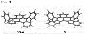
FIG. 3 illustrates optimized structures of Compound BD-A andCompound 9 obtained through a quantum calculation. -
- 1:
- Substrate
- 2:
- First Electrode
- 3:
- Organic Material Layer
- 4:
- Second Electrode
- 5:
- Hole Injection Layer
- 6:
- Hole Transfer Layer
- 7:
- Electron Blocking Layer
- 8:
- Light Emitting Layer
- 9:
- Electron Transfer Layer
- 10:
- Electron Injection Layer
- Hereinafter, the present specification will be described in more detail.
- One embodiment of the present specification provides a heterocyclic compound represented by Chemical Formula 1.
- In the present specification, a description of a certain part "including" certain constituents means capable of further including other constituents, and does not exclude other constituents unless particularly stated on the contrary.
- Examples of substituents in the present specification are described below, however, the substituents are not limited thereto.
- The term "substitution" means a hydrogen atom bonding to a carbon atom of a compound is changed to another substituent, and the position of substitution is not limited as long as it is a position at which the hydrogen atom is substituted, that is, a position at which a substituent can substitute, and when two or more substituents substitute, the two or more substituents may be the same as or different from each other.
- In the present specification, the term "substituted or unsubstituted" means being substituted with one, two or more substituents selected from the group consisting of deuterium; a nitrile group; a substituted or unsubstituted alkyl group; a substituted or unsubstituted cycloalkyl group; a substituted or unsubstituted silyl group; a substituted or unsubstituted aryl group; and a substituted or unsubstituted heterocyclic group, or substituted with a substituent linking two or more substituents among the substituents illustrated above, or having no substituents. For example, "a substituent linking two or more substituents" may include an aryl group substituted with an aryl group, an aryl group substituted with a heteroaryl group, a heterocyclic group substituted with an aryl group, an aryl group substituted with an alkyl group, and the like.
- In the present specification, examples of the halogen group may include a fluoro group, a chloro group, a bromo group, an iodo group and the like.
- In the present specification, the alkyl group may be linear or branched, and although not particularly limited thereto, the number of carbon atoms is preferably from 1 to 30. Specific examples thereof may include methyl, ethyl, propyl, n-propyl, isopropyl, butyl, n-butyl, isobutyl, tert-butyl, sec-butyl, 1-methyl-butyl, 1-ethyl-butyl, pentyl, n-pentyl, isopentyl, neopentyl, tert-pentyl, hexyl, n-hexyl, 1-methylpentyl, 2-methylpentyl, 4-methyl-2-pentyl, 3,3-dimethylbutyl, 2-ethylbutyl, heptyl, n-heptyl, 1-methylhexyl, cyclopentylmethyl, cyclohexylmethyl, octyl, n-octyl, tert-octyl, 1-methylheptyl, 2-ethylhexyl, 2-propylpentyl, n-nonyl, 2,2-dimethylheptyl, 1-ethyl-propyl, 1,1-dimethyl-propyl, isohexyl, 2-methylpentyl, 4-methylhexyl, 5-methylhexyl and the like, but are not limited thereto.
- In the present specification, the cycloalkyl group is not particularly limited, but preferably has 3 to 30 carbon atoms, and specific examples thereof may include cyclopropyl, cyclobutyl, cyclopentyl, 3-methylcyclopentyl, 2,3-dimethylcyclopentyl, cyclohexyl, 3-methylcyclohexyl, 4-methylcyclohexyl, 2,3-dimethylcyclohexyl, 3,4,5-trimethylcyclohexyl, 4-tert-butylcyclohexyl, cycloheptyl, cyclooctyl and the like, but are not limited thereto.
- In the present specification, the alkoxy group may be linear, branched or cyclic. The number of carbon atoms of the alkoxy group is not particularly limited, but is preferably from 1 to 30. Specifically, the number of carbon atoms is preferably from 1 to 20. More specifically, the number of carbon atoms is preferably from 1 to 10. Specific examples thereof may include a methoxy group; an ethoxy group; an n-propoxy group; an isopropoxy group; an i-propyloxy group; an n-butoxy group; an isobutoxy group; a tert-butoxy group; a sec-butoxy group; an n-pentyloxy group; a neopentyloxy group; an isopentyloxy group; an n-hexyloxy group; a 3,3-dimethylbutyloxy group; a 2-ethylbutyloxy group; an n-octyloxy group; an n-nonyloxy group; an n-decyloxy group; a benzyloxy group; a p-methylbenzyloxy group and the like, but are not limited thereto.
- In the present specification, specific examples of the silyl group may include a trimethylsilyl group, a triethylsilyl group, a t-butyldimethylsilyl group, a vinyldimethylsilyl group, a propyldimethylsilyl group, a triphenylsilyl group, a diphenylsilyl group, a phenylsilyl group and the like, but are not limited thereto.
- In the present specification, the aryl group is not particularly limited, but preferably has 6 to 30 carbon atoms, and the aryl group may be monocyclic or polycyclic.
- When the aryl group is a monocyclic aryl group, the number of carbon atoms is not particularly limited, but is preferably from 6 to 30. Specific examples of the monocyclic aryl group may include a phenyl group, a biphenyl group, a terphenyl group and the like, but are not limited thereto.
- When the aryl group is a polycyclic aryl group, the number of carbon atoms is not particularly limited, but is preferably from 10 to 30. Specific examples of the polycyclic aryl group may include a naphthyl group, an anthracenyl group, a phenanthryl group, a triphenyl group, a pyrenyl group, a phenalenyl group, a perylenyl group, a chrysenyl group, a fluorene group and the like, but are not limited thereto.
- In the present specification, the fluorene group may be substituted, and adjacent groups may bond to each other to form a ring.
- When the fluorene group is substituted,


- In the present specification, examples of the arylamine group include a substituted or unsubstituted monoarylamine group, a substituted or unsubstituted diarylamine group, or a substituted or unsubstituted triarylamine group. The aryl group in the arylamine group may be a monocyclic aryl group or a polycyclic aryl group. The arylamine group including two or more aryl groups may include monocyclic aryl groups, polycyclic aryl groups, or both monocyclic aryl groups and polycyclic aryl groups. For example, the aryl group in the arylamine group may be selected from among the examples of the aryl group described above.
- In the present specification, the heteroaryl group is a group including one or more atoms that are not carbon, that is, heteroatoms, and specifically, the heteroatom may include one or more atoms selected from the group consisting of O, N, Se, S and the like. The number of carbon atoms is not particularly limited, but is preferably from 2 to 30, and the heteroaryl group may be monocyclic or polycyclic. Examples of the heterocyclic group may include a thiophene group, a furanyl group, a pyrrole group, an imidazolyl group, a thiazolyl group, an oxazolyl group, an oxadiazolyl group, a pyridyl group, a bipyridyl group, a pyrimidyl group, a triazinyl group, a triazolyl group, an acridyl group, a pyridazinyl group, a pyrazinyl group, a quinolinyl group, a quinazolinyl group, a quinoxalinyl group, a phthalazinyl group, a pyridopyrimidyl group, a pyridopyrazinyl group, a pyrazinopyrazinyl group, an isoquinolinyl group, an indolyl group, a carbazolyl group, a benzoxazolyl group, a benzimidazolyl group, a benzothiazolyl group, a benzocarbazolyl group, a benzothiophene group, a dibenzothiophene group, a benzofuranyl group, a phenanthrolinyl group, an isoxazolyl group, a thiadiazolyl group, a phenothiazinyl group, a dibenzofuranyl group and the like, but are not limited thereto.
- In the present specification, examples of the heteroarylamine group include a substituted or unsubstituted monoheteroarylamine group, a substituted or unsubstituted diheteroarylamine group, or a substituted or unsubstituted triheteroarylamine group. The heteroarylamine group including two or more heteroaryl groups may include monocyclic heteroaryl groups, polycyclic heteroaryl groups, or both monocyclic heteroaryl groups and polycyclic heteroaryl groups. For example, the heteroaryl group in the heteroarylamine group may be selected from among the examples of the heteroaryl group described above.
- In the present specification, examples of the heteroaryl group in the N-arylheteroarylamine group and the N-alkylheteroarylamine group are the same as the examples of the heteroaryl group described above.
- In the present specification, "bonding to adjacent groups to form a ring" refers to bonding to substituents on ortho positions to form an aliphatic ring, an aromatic ring, or a heteroring including a heteroatom.
- According to one embodiment of the present specification,
Chemical Formula 1 is represented by any one of the followingChemical Formula 2 toChemical Formula 4. - According to one embodiment of the present specification,
Chemical Formula 1 is represented by the followingChemical Formula 

- In
Chemical Formulae
A1, A2, and R1 to R7 have the same definitions as inChemical Formula 1. - According to one embodiment of the present specification,
Chemical Formula 1 is represented by the followingChemical Formula 

- In
Chemical Formulae
A1, A2, and R5 to R7 have the same definitions as inChemical Formula 1,
Ra and Rb are the same as or different from each other, and each independently hydrogen, deuterium, a nitrile group, a halogen group, a substituted or unsubstituted alkyl group, a substituted or unsubstituted alkoxy group, a substituted or unsubstituted silyl group, a substituted or unsubstituted amine group, a substituted or unsubstituted aryl group, or a substituted or unsubstituted heteroaryl group, or adjacent substituents may bond to each other to form a substituted or unsubstituted ring,
k and 1 are each an integer of 0 to 4, and
when k and 1 are each a plural number, substituents in the parentheses are the same as or different from each other. - According to one embodiment of the present specification, R1 to R7, Ra and Rb are the same as or different from each other, and each independently hydrogen, deuterium, a nitrile group, a halogen group, a substituted or unsubstituted alkyl group, a substituted or unsubstituted silyl group, a substituted or unsubstituted alkoxy group, a substituted or unsubstituted amine group, a substituted or unsubstituted aryl group, or a substituted or unsubstituted heteroaryl group, or adjacent substituents may bond to each other to form a substituted or unsubstituted ring.
- According to one embodiment of the present specification, R1 to R7, Ra and Rb are the same as or different from each other, and each independently hydrogen; a nitrile group; a halogen group; an aryl group unsubstituted or substituted with a silyl group or an alkyl group; an alkyl group having 1 to 10 carbon atoms; a silyl group unsubstituted or substituted with an alkyl group having 1 to 10 carbon atoms; an alkoxy group having 1 to 10 carbon atoms; an amine group unsubstituted or substituted with an aryl group having 6 to 30 carbon atoms unsubstituted or substituted with an alkyl group; or a heteroaryl group having 3 to 30 carbon atoms and containing any one or more of N, O and S unsubstituted or substituted with an alkyl group having 1 to 10 carbon atoms.
- According to one embodiment of the present specification, R1 and R2 bond to each other to form a ring.
- According to one embodiment of the present specification, R3 and R4 bond to each other to form a ring.
- According to one embodiment of the present specification, R1 and R2 bond to each other to form an aromatic ring.
- According to one embodiment of the present specification, R3 and R4 bond to each other to form an aromatic ring.
- According to one embodiment of the present specification, R1 and R2 bond to each other to form a heteroring.
- According to one embodiment of the present specification, R3 and R4 bond to each other to form a heteroring.
- According to one embodiment of the present specification, R1 to R4 are the same as or different from each other, and each independently hydrogen, a halogen group, an alkyl group, an alkoxy group, a silyl group, or a substituted or unsubstituted aryl group.
- According to one embodiment of the present specification, R1 to R4 are the same as or different from each other, and each independently hydrogen; a halogen group; an alkyl group having 1 to 10 carbon atoms; an alkoxy group having 1 to 10 carbon atoms; a silyl group unsubstituted or substituted with an alkyl group having 1 to 10 carbon atoms; or an aryl group having 6 to 30 carbon atoms unsubstituted or substituted with an alkyl group or an alkylsilyl group.
- According to one embodiment of the present specification, R1 to R4 are the same as or different from each other, and each independently hydrogen; F; Cl; Br; I; a methyl group; an ethyl group; a propyl group; an isopropyl group; a butyl group; a tert-butyl group; a pentyl group; a hexyl group; a heptyl group; an octyl group; a methoxy group; an ethoxy group; a propoxy group; a butoxy group; a tert-butoxy group; a pentoxy group; a silyl group substituted with a methyl group; a phenyl group unsubstituted or substituted with an alkyl group having 1 to 10 carbon atoms or an alkylsilyl group having 1 to 10 carbon atoms; a biphenyl group; a terphenyl group; a naphthyl group; an anthracene group; a phenanthrene group;; a pyrene group; or a triphenylene group.
- According to one embodiment of the present specification, R1 to R4 are the same as or different from each other, and each independently hydrogen; F; a methyl group; a tert-butyl group; a methoxy group; a trimethylsilyl group; or a phenyl group unsubstituted or substituted with a methyl group, a tert-butyl group or a trimethylsilyl group.
- According to one embodiment of the present specification, R5 and R7 are hydrogen.
- According to one embodiment of the present specification, R6 is hydrogen; an alkyl group; a silyl group substituted with an alkyl group; a silyl group substituted with an aryl group; an alkoxy group substituted with a halogen group; an alkoxy group; an aryl group; an aryl group substituted with an aryl group; a cycloalkyl group; an amine group substituted with an aryl group unsubstituted or substituted with an alkyl group; or an N, O or S-containing heterocyclic group having 3 to 30 carbon atoms.
- According to one embodiment of the present specification, R6 is hydrogen; an alkyl group having 1 to 10 carbon atoms; a silyl group substituted with an alkyl group having 1 to 10 carbon atoms; a silyl group substituted with an aryl group having 6 to 30 carbon atoms; an aryl group having 6 to 30 carbon atoms; an alkoxy group having 1 to 10 carbon atoms substituted with a halogen group; an alkoxy group having 1 to 10 carbon atoms; an amine group substituted with an aryl group having 6 to 30 carbon atoms unsubstituted or substituted with an alkyl group having 1 to 10 carbon atoms; a cycloalkyl group having 3 to 20 carbon atoms; or a monocyclic or polycyclic heterocyclic group containing N, O or S.
- According to one embodiment of the present specification, R6 is hydrogen; a methyl group; a tert-butyl group; a phenyl group substituted with a phenyl group; a biphenyl group; a phenyl group; a terphenyl group; an arylamine group unsubstituted or substituted with a methyl group or a tert-butyl group; a silyl group substituted with a methyl group; a silyl group substituted with a phenyl group; a methoxy group substituted with a fluoro group; a methoxy group; a cyclohexyl group; an adamantly group; a carbazole group; a pyridine group; a pyrimidine group; a triazine group; a furan group; a thiophene group; a benzofuran group; a benzothiophene group; a dibenzofuran group; a dibenzothiophene group; an imidazole group; a phenoxazine group; a phenothiazine group; or a dimethyldihydroacridine group.
- According to one embodiment of the present specification, R6 is hydrogen, a tert-butyl group, a phenyl group, an amine group substituted with a phenyl group unsubstituted or substituted with a tert-butyl group, a trifluoromethoxy group, a trimethylsilyl group, a triphenylsilyl group, a cyclohexyl group, an adamantly group, a carbazole group, a phenoxazine group, a phenothiazine group or a dimethyldihydroacridine group.
- According to one embodiment of the present specification, R6 bonds to A1 and A2 to form a substituted or unsubstituted heteroring.
- According to one embodiment of the present specification, R6 bonds to A1 and A2 to form a heteroring unsubstituted or substituted with an alkyl group or an aryl group.
- According to one embodiment of the present specification, R6 bonds to A1 and A2 to form a heteroring including any one or more of N, O and S unsubstituted or substituted with an alkyl group or an aryl group.
- According to one embodiment of the present specification, Ra and Rb are the same as or different from each other, and each independently hydrogen, a halogen group, an alkyl group, an alkoxy group, an alkylsilyl group, or an aryl group unsubstituted or substituted with an alkyl group or an alkylsilyl group.
- According to one embodiment of the present specification, Ra and Rb are the same as or different from each other, and each independently hydrogen, a halogen group, an alkyl group having 1 to 10 carbon atoms, an alkoxy group having 1 to 10 carbon atoms, a silyl group substituted with an alkyl group having 1 to 10 carbon atoms, or an aryl group having 6 to 20 carbon atoms unsubstituted or substituted with an alkyl group or an alkylsilyl group.
- According to one embodiment of the present specification, Ra and Rb are the same as or different from each other, and each independently hydrogen; F; Cl; Br; I; a methyl group; an ethyl group; a propyl group; an isopropyl group; a butyl group; a tert-butyl group; a methoxy group; an ethoxy group; a propoxy group; an isopropoxy group; a tert-butoxy group; a butoxy group; a trimethylsilyl group; a phenyl group unsubstituted or substituted with an alkyl group or an alkylsilyl group; a biphenyl group unsubstituted or substituted with an alkyl group or an alkylsilyl group; a terphenyl group unsubstituted or substituted with an alkyl group or an alkylsilyl group; a naphthyl group unsubstituted or substituted with an alkyl group or an alkylsilyl group; an anthracene group unsubstituted or substituted with an alkyl group or an alkylsilyl group; or a phenanthrene group unsubstituted or substituted with an alkyl group or an alkylsilyl group.
- According to one embodiment of the present specification, Ra and Rb are the same as or different from each other, and each independently hydrogen; a fluoro group; a methyl group; a tert-butyl group; a methoxy group; a phenyl group unsubstituted or substituted with a trimethylsilyl group or a tert-butyl group; or a trimethylsilyl group.
- According to one embodiment of the present specification, A1 and A2 are the same as or different from each other, and each independently an aryl group unsubstituted or substituted with a substituted or unsubstituted alkyl group, or a substituted or unsubstituted heteroaryl group.
- According to one embodiment of the present specification, A1 and A2 are the same as or different from each other, and each independently a substituted or unsubstituted an aryl group having 6 to 30 carbon atoms, or a substituted or unsubstituted N, O or S-containing heteroaryl group having 3 to 30 carbon atoms.
- According to one embodiment of the present specification, A1 and A2 are the same as or different from each other, and each independently a substituted or unsubstituted monocyclic aryl group having 6 to 30 carbon atoms, a substituted or unsubstituted polycyclic aryl group having 10 to 30 carbon atoms, a substituted or unsubstituted N, O or S-containing monocyclic heteroaryl group having 3 to 30 carbon atoms, or a substituted or unsubstituted N, O or S-containing polycyclic heteroaryl group having 3 to 30 carbon atoms.
- According to one embodiment of the present specification, A1 and A2 are the same as or different from each other, and each independently an aryl group having 6 to 30 carbon atoms, and examples of the aryl group having 6 to 30 carbon atoms may include a phenyl group, a biphenyl group, a terphenyl group, a naphthyl group, a fluorene group, an anthracene group, a phenanthrene group, a triphenylene group or a pyrene group, but are not limited thereto, and
- may be unsubstituted or substituted with one or more substituents selected from the group consisting of deuterium, a nitrile group, a halogen group, an alkyl group having 1 to 10 carbon atoms, a cycloalkyl group having 3 to 30 carbon atoms, a silyl group substituted with an alkyl group having 1 to 10 carbon atoms, an aryl group having 6 to 30 carbon atoms, and a heteroaryl group having 3 to 30 carbon atoms.
- According to one embodiment of the present specification, A1 and A2 are the same as or different from each other, and each independently an aryl group having 6 to 30 carbon atoms unsubstituted or substituted with an alkyl group having 1 to 10 carbon atoms, a cycloalkyl group having 3 to 30 carbon atoms, or a silyl group substituted with an alkyl group having 1 to 10 carbon atoms.
- According to one embodiment of the present specification, A1 and A2 are the same as or different from each other, and each independently a phenyl group that is unsubstituted or substituted with an alkyl group having 1 to 10 carbon atoms, a cycloalkyl group having 3 to 30 carbon atoms, or a silyl group substituted with an alkyl group having 1 to 10 carbon atoms
- According to one embodiment of the present specification, A1 and A2 are the same as or different from each other, and each independently a phenyl group unsubstituted or substituted with a methyl group, a phenyl group unsubstituted or substituted with an ethyl group, a phenyl group unsubstituted or substituted with a propyl group, a phenyl group unsubstituted or substituted with an isopropyl group, a phenyl group unsubstituted or substituted with a butyl group, a phenyl group unsubstituted or substituted with a tert-butyl group, a phenyl group unsubstituted or substituted with a cyclohexyl group, or a phenyl group unsubstituted or substituted with a trimethylsilyl group.
- According to one embodiment of the present specification, A1 and A2 are the same as or different from each other, and each independently a phenyl group unsubstituted or substituted with a methyl group, a tert-butyl group, a cyclohexyl group or a trimethylsilyl group.
- According to one embodiment of the present specification, A1 and A2 may be represented by the following substituents.

- According to one embodiment of the present specification, A1 and A2 are the same as or different from each other, and each independently a phenyl group unsubstituted or substituted with a methyl group, a tert-butyl group or a cyclohexyl group, or a biphenyl group unsubstituted or substituted with a tert-butyl group.
- According to one embodiment of the present specification, A1 and R5 bond to each other to form a substituted or unsubstituted ring.
- According to one embodiment of the present specification, A2 and R7 bond to each other to form a substituted or unsubstituted ring.
- According to one embodiment of the present specification, A1 and R5 bond to each other to form a substituted or unsubstituted heteroring.
- According to one embodiment of the present specification, A2 and R7 bond to each other to form a substituted or unsubstituted heteroring.
- According to one embodiment of the present specification, A1 and R5 bond to each other to form an N, O or S-including heteroring unsubstituted or substituted with an alkyl group having 1 to 10 carbon atoms.
- According to one embodiment of the present specification, A2 and R7 bond to each other to form an N, O or S-including heteroring unsubstituted or substituted with an alkyl group having 1 to 10 carbon atoms.
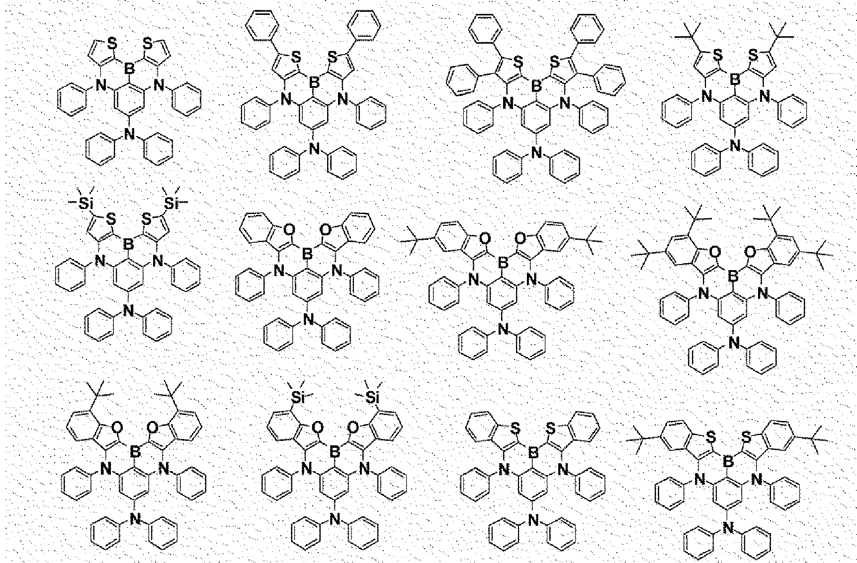
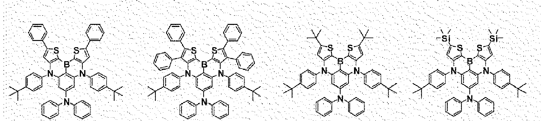
- According to another embodiment of the present specification, the heterocyclic compound of
Chemical Formula 1 may be represented by the following structural formulae.








- In addition, an organic electroluminescent device according to the present disclosure includes an anode; a cathode provided opposite to the anode; and a hole injection layer, a hole transfer layer, or a layer carrying out hole injection and transfer at the same time between the anode and the cathode, wherein the hole injection layer, the hole transfer layer, or the layer carrying out hole injection and transfer at the same time includes the heterocyclic compound represented by
Chemical Formula 1. - The organic light emitting device of the present disclosure may be manufactured using common organic light emitting device manufacturing methods and materials except that one or more organic material layers are formed using the above-described compound.
- The organic material layer of the organic light emitting device of the present disclosure may be formed in a single layer structure, but may also be formed in a multilayer structure in which two or more organic material layers are laminated. For example, the organic light emitting device of the present disclosure may have a structure including a hole injection layer, a hole transfer layer, a light emitting layer, an electron transfer layer, an electron injection layer and the like as the organic material layer. However, the structure of the organic light emitting device is not limited thereto, and may include a smaller number of organic material layers. In addition, the organic material layer may include one or more of an electron transfer layer, an electron injection layer, and a layer carrying out electron transfer and electron injection at the same time, and one or more layers of the above-described layers may include the compound.
- For example, the organic light emitting device of the present disclosure may have structures as illustrated in
FIG. 1 and FIG. 2 , however, the structure is not limited thereto. -
FIG. 1 illustrates a structure of the organic light emitting device in which a first electrode (2), an organic material layer (3) and a second electrode (4) are consecutively laminated on a substrate (1). -
FIG. 1 illustrates the organic light emitting device, and the structure is not limited thereto. -
FIG. 2 illustrates a structure of the organic light emitting device in which a first electrode (2), a hole injection layer (5), a hole transfer layer (6), an electron blocking layer (7), a light emitting layer (8), an electron transfer layer (9), an electron injection layer (10) and a second electrode (4) are consecutively laminated on a substrate (1) . -
FIG. 2 illustrates the organic light emitting device, and the structure is not limited thereto. - In one embodiment of the present disclosure, the organic light emitting device has a structure consecutively laminating a substrate/a first electrode/an organic material layer/a second electrode.
- In one embodiment of the present disclosure, the organic light emitting device has a structure consecutively laminating a substrate/a first electrode/an organic material layer/a light emitting layer/a second electrode.
- In one embodiment of the present disclosure, the organic light emitting device has a structure consecutively laminating a substrate/a first electrode/a light emitting layer/an organic material layer/a second electrode.
- In one embodiment of the present disclosure, the organic light emitting device has a structure consecutively laminating a substrate/a first electrode/an organic material layer/a light emitting layer/an organic material layer/a second electrode.
- In one embodiment of the present disclosure, the organic light emitting device has a structure consecutively laminating a substrate/a first electrode/a hole injection layer/a light emitting layer/an organic material layer/a second electrode.
- In one embodiment of the present disclosure, the organic light emitting device has a structure consecutively laminating a substrate/a first electrode/a hole injection layer/an electron blocking layer/a light emitting layer/an electron injection layer/a second electrode.
- In one embodiment of the present disclosure, the organic light emitting device has a structure consecutively laminating a substrate/a first electrode/a hole injection layer/an electron blocking layer/a light emitting layer/an electron transfer layer/an electron injection layer/a second electrode.
- In one embodiment of the present disclosure, the organic light emitting device has a structure consecutively laminating a substrate/a first electrode/a hole injection layer/a hole transfer layer/an electron blocking layer/a light emitting layer/a hole blocking layer/an electron transfer layer/an electron injection layer/a second electrode.
- In one embodiment of the present disclosure, the organic material layer including the heterocyclic compound of
Chemical Formula 1 includes a light emitting layer, and may include the heterocyclic compound ofChemical Formula 1 in the light emitting layer. - In one embodiment of the present disclosure, the organic material layer including the heterocyclic compound of
Chemical Formula 1 includes a light emitting layer, and includes a host and a dopant in the light emitting layer. - In one embodiment of the present disclosure, the organic material layer including the heterocyclic compound of
Chemical Formula 1 includes a light emitting layer, and includes a host and a dopant in the light emitting layer in a weight ratio of 99:1 to 1:99. - In one embodiment of the present disclosure, the organic material layer including the heterocyclic compound of
Chemical Formula 1 includes a light emitting layer, and includes a host and a dopant in the light emitting layer in a weight ratio of 99:1 to 50:50. - In one embodiment of the present disclosure, the organic material layer including the heterocyclic compound of
Chemical Formula 1 includes a light emitting layer, and includes the heterocyclic compound ofChemical Formula 1 as a dopant in the light emitting layer. - In one embodiment of the present disclosure, the organic material layer including the heterocyclic compound of
Chemical Formula 1 includes a light emitting layer, and may use an organic compound as a host of the light emitting layer. - In one embodiment of the present disclosure, the organic material layer including the heterocyclic compound of
Chemical Formula 1 includes a light emitting layer, and may use an anthracene-based organic compound as a host of the light emitting layer. - In one embodiment of the present disclosure, the organic material layer including the heterocyclic compound of
Chemical Formula 1 includes an electron injection layer, an electron transfer layer, an electron injection and transfer layer, or a hole blocking layer, and may include the heterocyclic compound ofChemical Formula 1 in the electron injection layer, the electron transfer layer, the electron injection and transfer layer, or the hole blocking layer. - In one embodiment of the present disclosure, the organic material layer including the heterocyclic compound of
Chemical Formula 1 includes a hole injection layer, a hole transfer layer, a hole injection and transfer layer, and an electron blocking layer, and may include the heterocyclic compound ofChemical Formula 1 in the hole injection layer, the hole transfer layer, the hole injection and transfer layer, and the electron blocking layer. - For example, the organic light emitting device according to the present disclosure may be manufactured by forming an anode on a substrate by depositing a metal, a metal oxide having conductivity, or an alloy thereof using a physical vapor deposition (PVD) method such as sputtering or e-beam evaporation, and forming an organic material layer including a hole injection layer, a hole transfer layer, a light emitting layer and an electron transfer layer, and an organic material layer including the heterocyclic compound of
Chemical Formula 1, and then depositing a material capable of being used as a cathode thereon. In addition to such a method, the organic light emitting device may also be manufactured by consecutively depositing a cathode material, an organic material layer and an anode material on a substrate. - As the anode material, materials having large work function are normally preferred so that hole injection to an organic material layer is smooth. Specific examples of the anode material capable of being used in the present disclosure include metals such as vanadium, chromium, copper, zinc and gold, or alloys thereof; metal oxides such as zinc oxide, indium oxide, indium tin oxide (ITO) and indium zinc oxide (IZO); combinations of metals and oxides such as ZnO:Al or SnO2:Sb; conductive polymers such as poly (3-methylthiophene), poly[3,4-(ethylene-1,2-dioxy)thiophene] (PEDT), polypyrrole and polyaniline, but are not limited thereto.
- As the cathode material, materials having small work function are normally preferred so that electron injection to an organic material layer is smooth. Specific examples of the cathode material include metals such as magnesium, calcium, sodium, potassium, titanium, indium, yttrium, lithium, gadolinium, aluminum, silver, tin and lead, or alloys thereof; multilayer structure materials such as LiF/Al or LiO2/Al, and the like, but are not limited thereto.
- The hole injection material is a material capable of favorably receiving holes from an anode at a low voltage, and the highest occupied molecular orbital (HOMO) of the hole injection material is preferably in between the work function of an anode material and the HOMO of surrounding organic material layers. Specific examples of the hole injection material include metal porphyrins, oligothiophene, arylamine-based organic materials, hexanitrile hexaazatriphenylene-based organic materials, quinacridone-based organic materials, perylene-based organic materials, anthraquinone, and polyaniline- and polythiophene-based conductive polymers, and the like, but are not limited thereto.
- The hole transfer material is a material capable of receiving holes from an anode or a hole injection layer, moving the holes to a light emitting layer, and materials having high mobility for the holes are suited. Specific examples thereof include arylamine-based organic materials, conductive polymers, block copolymers having conjugated parts and non-conjugated parts together, and the like, but are not limited thereto.
- The light emitting material is a material capable of emitting light in a visible light region by receiving holes and electrons from a hole transfer layer and an electron transfer layer, respectively, and binding the holes and the electrons, and is preferably a material having favorable quantum efficiency for fluorescence or phosphorescence. Specific examples thereof include 8-hydroxy-quinoline aluminum complexes (Alq3); carbazole-based compounds; dimerized styryl compounds; BAlq; 10-hydroxybenzoquinoline-metal compounds; benzoxazole-, benzothiazole- and benzimidazole-based compounds; poly(p-phenylenevinylene) (PPV)-based polymers; spiro compounds; polyfluorene, rubrene, and the like, but are not limited thereto.
- The light emitting layer may include a host material and a dopant material. The host material includes fused aromatic ring derivatives, heteroring-containing compounds or the like. Specifically, the fused aromatic ring derivative includes anthracene derivatives, pyrene derivatives, naphthalene derivatives, pentacene derivatives, phenanthrene compounds, fluoranthene compounds and the like, and the heteroring-containing compound includes heterocyclic compounds, dibenzofuran derivatives, ladder-type furan compounds, pyrimidine derivatives and the like, however, the material is not limited thereto.
- When the organic light emitting device includes a plurality of organic material layers, the organic material layers may be formed with materials the same as or different from each other.
- The organic light emitting device of the present specification may be manufactured using materials and methods known in the art except that one or more layers of the organic material layers are formed using the heterocyclic compound.
- For example, the organic light emitting device of the present specification may be manufactured by consecutively laminating an anode, an organic material layer and a cathode on a substrate. Herein, the organic light emitting device may be manufactured by forming an anode on a substrate by depositing a metal, a metal oxide having conductivity, or an alloy thereof using a physical vapor deposition (PVD) method such as sputtering or e-beam evaporation, and forming an organic material layer including a hole injection layer, a hole transfer layer, a light emitting layer and an electron transfer layer thereon, and then depositing a material capable of being used as a cathode thereon. In addition to such a method, the organic light emitting device may also be manufactured by consecutively depositing a cathode material, an organic material layer and an anode material on a substrate.
- Another embodiment of the present specification provides a method for manufacturing an organic light emitting device formed using the heterocyclic compound.
- Specifically, the method in one embodiment of the present specification includes preparing a substrate; forming a cathode or an anode on the substrate; forming one or more organic material layers on the cathode or the anode; and forming an anode or a cathode on the organic material layer, wherein one or more layers of the organic material layers are formed using the heterocyclic compound.
- The electron transfer layer is a layer that receives electrons from an electron injection layer and transfers the electrons to a light emitting layer, and as the electron transfer material, materials capable of favorably receiving electrons from a cathode, moving the electrons to a light emitting layer, and having high mobility for the electrons are suited. Specific examples thereof include Al complexes of 8-hydroxyquinoline; complexes including Alq3; organic radical compounds; hydroxyflavon-metal complexes, and the like, but are not limited thereto. The electron transfer layer may be used together with any desired cathode material as used in the art. Particularly, examples of the suitable cathode material include common materials that have small work function, and in which an aluminum layer or a silver layer follows. Specifically, the cathode material includes cesium, barium, calcium, ytterbium and samarium, and in each case, an aluminum layer or a silver layer follows.
- The electron injection layer is a layer that injects electrons from an electrode, and compounds that have an ability to transfer electrons, have an electron injection effect from a cathode, have an excellent electron injection effect for a light emitting layer or a light emitting material, prevent excitons generated in the light emitting layer from moving to a hole injection layer, and in addition thereto, have an excellent thin film forming ability are preferred. Specific examples thereof include fluorenone, anthraquinodimethane, diphenoquinone, thiopyran dioxide, oxazole, oxadiazole, triazole, imidazole, perylene tetracarboxylic acid, fluorenylidene methane, anthrone or the like, and derivatives thereof, metal complex compounds, nitrogen-containing 5-membered ring derivatives, and the like, but are not limited there.
- The metal complex compound includes 8-hydroxyquinolinato lithium, bis(8-hydroxyquinolinato)zinc, bis(8-hydroxyquinolinato)copper, bis(8-hydroxyquinolinato)manganese, tris(8-hydroxyquinolinato)aluminum, tris(2-methyl-8-hydroxyquinolinato)aluminum, tris(8-hydroxyquinolinato)gallium, bis(10-hydroxybenzo[h]quinolinato)beryllium, bis(10-hydroxybenzo[h]quinolinato)zinc, bis(2-methyl-8-quinolinato)chlorogallium, bis(2-methyl-8-quinolinato)(o-cresolato)gallium, bis(2-methyl-8-quinolinato)(1-naphtholato)aluminum, bis(2-methyl-8-quinolinato)(2-naphtholato)gallium and the like, but is not limited thereto.
- The hole blocking layer is a layer preventing holes from reaching a cathode, and may be generally formed under the same condition as a hole injection layer. Specific examples thereof may include oxadiazole derivatives, triazole derivatives, phenanthroline derivatives, BCP, aluminum complexes and the like, but are not limited thereto.
- The organic light emitting device according to the present specification may be a top-emission type, a bottom-emission type or a dual-emission type depending on the materials used.
-

- In a 3-neck flask, 3-bromobenzofuran (15.0 g, 76.1 mmol) and 4-(tert-butyl)aniline (12.5 g, 83.7 mmol) were dissolved in toluene (450 ml), and after introducing sodium tert-butoxide (11.0 g, 114.2 mmol) and bis(tri-tert-butylphosphine)palladium(0) (0.8 g, 1.5 mmol) thereto, the result was stirred for 6 hours under an argon atmosphere reflux condition. When the reaction was finished, the result was cooled to room temperature, H2O was introduced thereto, and the reaction solution was transferred to a separatory funnel and extracted. The extract was dried with MgSO4 and concentrated, and the sample was purified using silica gel column chromatography to obtain Compound 1-a (15.2 g). (Yield 75%, MS[M+H]+=265)
-

- In a 3-neck flask, Compound 1-a (15.0 g, 56.5 mmol) and 1-bromo-2,3-dichlorobenzene (6.4 g, 28.3 mmol) were dissolved in toluene (300 ml), and after introducing sodium tert-butoxide (10.9 g, 113.1 mmol) and bis(tri-tert-butylphosphine)palladium(0) (0.6 g, 1.1 mmol) thereto, the result was stirred for 6 hours under an argon atmosphere reflux condition. When the reaction was finished, the result was cooled to room temperature, H2O was introduced thereto, and the reaction solution was transferred to a separatory funnel and extracted. The extract was dried with MgSO4 and concentrated, and the sample was purified using silica gel column chromatography to obtain Compound 1-b (27.5 g). (Yield 76%, MS [M+H]+=639)
-

- In a 3-neck flask, Compound 1-b (25.0 g, 39.1 mmol) was dissolved in tert-butylbenzene (500 ml), and cooled to 0°C. Under the nitrogen atmosphere, 1.7 M tert-butylithium in pentane (35 ml, 58.7 mmol) was added thereto, and the result was stirred for 2 hours at 60°C. After that, the reaction material was cooled again to 0°C, BBr3 (6 ml, 58.7 mmol) was added thereto, and the result was stirred for 0.5 hours at room temperature. The reaction material was cooled again to 0°C, and after adding N,N-diisopropylethylamine (10 ml, 58.7 mmol) thereto, the result was stirred for 2 hours at 60°C. When the reaction was finished, the result was cooled to room temperature, and extracted in a separatory funnel using ethyl acetate and H2O. The extract was dried with MgSO4 and concentrated, and the sample was purified using silica gel column chromatography and then sublimation purified to obtain Compound 1 (2.6 g). (Yield 11%, MS[M+H]+=612)
-

- In a 3-neck flask, 4-(trifluoromethoxy)aniline (15.0 g, 84.7 mmol) and potassium iodide (35.1 g, 211.7 mmol) were dissolved in concentrated H2SO4 (1 ml) and MeOH (420 ml), and the result was stirred for 4 hours at room temperature while slowly adding 30% H2O2 (1 ml). When the reaction was finished, the result was extracted in a separatory funnel using dichloromethane and H2O. The extract was washed consecutively with an aqueous NaHSO3 solution and H2O, then dried with MgSO4 and concentrated, and the sample was purified using silica gel column chromatography to obtain Compound 2-a (25.4 g). (Yield 70%, MS[M+H]+=428)
-

- Compound 2-a (20.0 g, 46.6 mmol) and acetic acid (100 ml) were introduced to a 3-neck flask, and cooled to 0°C. Under the nitrogen atmosphere, sodium nitrite (4.8 g, 69.9 mmol) dissolved in H2O (20 ml) and then concentrated H2SO4 (20 ml) were added thereto, and the result was stirred for 0.5 hours. After that, copper bromide (14.7 g, 102.6 mmol) dissolved in a 45% aqueous HBr solution (340 ml) was added thereto at room temperature, and the result was stirred for 1 hour. When the reaction was finished, the result was extracted in a separatory funnel using ethyl acetate and H2O. H2O was introduced thereto, and the reaction solution was transferred to a separatory funnel and extracted. The result was washed consecutively with an aqueous NaHCO3 solution and H2O, dried with MgSO4 and concentrated, and the sample was purified using silica gel column chromatography to obtain Compound 2-b (16.1 g). (Yield 70%, MS[M+H]+=492)
-

- In a 3-neck flask, Compound 2-b (15.0 g, 30.4 mmol) and Compound 1-a (8.9 g, 33.5 mmol) were dissolved in toluene (450 ml), and after introducing sodium tert-butoxide (4.4 g, 45.7 mmol) and bis(tri-tert-butylphosphine)palladium(0) (0.3 g, 0.6 mmol) thereto, the result was stirred for 6 hours under an argon atmosphere reflux condition. When the reaction was finished, the result was cooled to room temperature, H2O was introduced thereto, and the reaction solution was transferred to a separatory funnel and extracted. The extract was dried with MgSO4 and concentrated, and the sample was purified using silica gel column chromatography to obtain Compound 2-c (15.9 g). (Yield 72%, MS[M+H]+=723)
-

- In a 3-neck flask, Compound 2-c (15.0 g, 20.7 mmol) was dissolved in tert-butylbenzene (300 ml), and cooled to 0°C. Under the nitrogen atmosphere, 1.7 M tert-butylithium in pentane (18 ml, 31.1 mmol) was added thereto, and the result was stirred for 2 hours at 60°C. After that, the reaction material was cooled again to 0°C, BBr3 (3 ml, 31.1 mmol) was added thereto, and the result was stirred for 0.5 hours at room temperature. The reaction material was cooled again to 0°C, and after adding N,N-diisopropylethylamine (5 ml, 31.1 mmol) thereto, the result was stirred for 2 hours at 60°C. When the reaction was finished, the result was cooled to room temperature, and extracted in a separatory funnel using ethyl acetate and H2O. The extract was dried with MgSO4 and concentrated, and the sample was purified using silica gel column chromatography and then sublimation purified to obtain Compound 2 (1.7 g). (Yield 12%, MS[M+H]+=696)
-

-
Compound 3 was obtained in the same manner as in the method for preparingCompound 2 in Synthesis Example 2 except that 4-cyclohexylaniline was used instead of 4-(trifluoromethoxy)aniline. (MS[M+H]+=694) -


-
Compound 4 was obtained in the same manner as in the method for preparingCompound 2 in Synthesis Example 2 except that 4-((3r,5r,7r)-adamantan-1-yl)aniline was used instead of 4-(trifluoromethoxy)aniline. (MS[M+H]+=746) -

- In a 3-neck flask, 2-bromo-4-chlorofuran (20.0 g, 110.2 mmol) and phenylboronic acid (14.1 g, 115.8 mmol) were dissolved in THF (400 ml), and potassium carbonate (91.4 g, 661.5 mmol) dissolved in H2O (133 ml) was introduced thereto. Tetrakis(triphenylphosphine)palladium(0) (2.5 g, 2.2 mmol) was introduced thereto, and the result was stirred for 8 hours under an argon atmosphere reflux condition. When the reaction was finished, the result was cooled to room temperature, and the reaction solution was transferred to a separatory funnel and extracted with ethyl acetate. The extract was dried with MgSO4 and concentrated, and the sample was purified using silica gel column chromatography to obtain Compound 5-a (16.0 g).
-

-
Compound 5 was obtained in the same manner as in the method for preparingCompound 1 in Synthesis Example 1 except that Compound 5-a was used instead of 3-bromobenzofuran, and aniline was used instead of 4-(tert-butyl)aniline. -

- In a 3-neck flask, Compound 5-a (15.0 g, 84.0 mmol) and 4-(tert-butyl)aniline (13.2 g, 88.2 mmol) were dissolved in toluene (450 ml), and after introducing sodium tert-butoxide (12.1 g, 126.0 mmol) and bis(tri-tert-butylphosphine)palladium(0) (0.9 g, 1.7 mmol) thereto, the result was stirred for 6 hours under an argon atmosphere reflux condition. When the reaction was finished, the result was cooled to room temperature, H2O was introduced thereto, and the reaction solution was transferred to a separatory funnel and extracted. The extract was dried with MgSO4 and concentrated, and the sample was purified using silica gel column chromatography to obtain Compound 6-a (17.4 g). (Yield 71%, MS[M+H]+=291)
-

- In a 3-neck flask, Compound 6-a (15.0 g, 51.5 mmol) and 1,2-dibromo-5-chloro-3-iodobenzene (9.5 g, 25.7 mmol) were dissolved in toluene (300 ml), and after introducing sodium tert-butoxide (9.9 g, 103.0 mmol) and bis(tri-tert-butylphosphine)palladium(0) (0.5 g, 1.0 mmol) thereto, the result was stirred for 6 hours under an argon atmosphere reflux condition. When the reaction was finished, the result was cooled to room temperature, H2O was introduced thereto, and the reaction solution was transferred to a separatory funnel and extracted. The extract was dried with MgSO4 and concentrated, and the sample was purified using silica gel column chromatography to obtain Compound 6-b (24.3 g). (Yield 77%, MS[M+H]+=613)
-

- In a 3-neck flask, Compound 6-b (24.0 g, 39.1 mmol) was dissolved in tert-butylbenzene (480 ml), and cooled to 0°C. Under the nitrogen atmosphere, 1.7 M tert-butylithium in pentane (35 ml, 58.7 mmol) was added thereto, and the result was stirred for 2 hours at 60°C. After that, the reaction material was cooled again to 0°C, BBr3 (6 ml, 58.7 mmol) was added thereto, and the result was stirred for 0.5 hours at room temperature. The reaction material was cooled again to 0°C, and after adding N,N-diisopropylethylamine (10 ml, 58.7 mmol) thereto, the result was stirred for 2 hours at 60°C. When the reaction was finished, the result was cooled to room temperature, and extracted in a separatory funnel using ethyl acetate and H2O. The extract was dried with MgSO4 and concentrated, and the sample was purified using silica gel column chromatography to obtain Compound 6-c (6.3 g). (Yield 23%, MS[M+H]+=699)
-

- In a 3-neck flask, Compound 6-c (6.0 g, 8.6 mmol) and diphenylamine (1.6 g, 9.4 mmol) were dissolved in toluene (150 ml), and after introducing sodium tert-butoxide (1.2 g, 12.9 mmol) and bis(tri-tert-butylphosphine)palladium(0) (0.1 g, 0.2 mmol) thereto, the result was stirred for 6 hours under an argon atmosphere reflux condition. When the reaction was finished, the result was cooled to room temperature, H2O was introduced thereto, and the reaction solution was transferred to a separatory funnel and extracted. The extract was dried with MgSO4 and concentrated, and the sample was purified using silica gel column chromatography and then sublimation purified to obtain Compound 6 (2.5 g). (Yield 35%, MS[M+H]+=831)
-

-
Compound 7 was obtained in the same manner as in the method for preparingCompound 1 in Synthesis Example 1 except that 3-bromobenzo[b]thiophene was used instead of 3-bromobenzofuran, and aniline was used instead of 4-(tert-butyl)aniline. (MS[M+H]+=532) -

-
Compound 8 was obtained in the same manner as in the method for preparingCompound 1 in Synthesis Example 1 except that 3-bromobenzo[b]thiophene was used instead of 3-bromobenzofuran, and 4-(trimethylsilyl)aniline was used instead of 4-(tert-butyl)aniline. (MS[M+H]+=676) - A glass substrate on which indium tin oxide (ITO) was coated as a thin film to a thickness of 1,400 Å was placed in detergent-dissolved distilled water and ultrasonic cleaned. Herein, a Decon™ CON705 product of Fischer Co. was used as the detergent, and as the distilled water, distilled water filtered twice with a 0.22 µm sterilizing filter manufactured by Millipore Co. was used. After the ITO was cleaned for 30 minutes, ultrasonic cleaning was repeated twice using distilled water for 10 minutes. After the cleaning with distilled water was finished, the substrate was ultrasonic cleaned with solvents of isopropyl alcohol, acetone and methanol for 10 minutes each, then dried, and then transferred to a plasma cleaner. In addition, the substrate was cleaned for 5 minutes using oxygen plasma, and then transferred to a vacuum deposition apparatus.
- On the transparent ITO electrode prepared as above, a hole injection layer was formed by consecutively thermal vacuum depositing the following HI-A and LG-101 to thicknesses of 650 Å and 50 Å, respectively. As a hole transfer layer, the following HT-A was vacuum deposited to a thickness of 600 Å, and then the following HT-B was thermal vacuum deposited to a thickness of 50 Å as an electron blocking layer. Subsequently, as a light emitting layer, BH-A and
Compound 1 were vacuum deposited to a thickness of 200 Å in a weight ratio of 96:4. Subsequently, as an electron transfer layer, compounds represented by ET and Liq were thermal vacuum deposited to a thickness of 360 Å in a weight ratio of 1:1, and then a compound represented by the following Liq was vacuum deposited to a thickness of 5 Å to form an electron injection layer. On the electron injection layer, a cathode was formed by consecutively depositing magnesium and silver to a thickness of 220 Å in a weight ratio of 10:1 and then aluminum to a thickness of 1000 Å, and an organic light emitting device was manufactured.


- Organic light emitting devices of Example 2 to Example 8 and Comparative Example 1 to Comparative Example 3 were each manufactured in the same manner as in Example 1 except that, as a dopant material, compounds described in Table 1 were used instead.

- Voltage, efficiency and lifetime (T95) were measured by applying a current to each of the organic light emitting devices manufactured in Example 1 to Example 8 and Comparative Example 1 to Comparative Example 3, and the results are shown in the following Table 1. Herein, the voltage and the efficiency were measured by applying current density of 10 mA/cm2, and FWHM (full width at half maximum) was obtained from a spectrum measured herein. T95 means time taken for initial luminance decreasing to 95% at current density of 20 mA/cm2.
[Table 1] Dopant @ 10 mA/cm2 @20 mA/cm2 V QE FWHM (nm) LT95 Example 1 Compound 13.88 7.61 21 110 Example 2 Compound 23.92 7.76 20 105 Example 3 Compound 33.93 7.76 21 106 Example 4 Compound 43.96 7.58 20 101 Example 5 Compound 53.85 7.65 20 119 Example 6 Compound 63.91 7.63 21 115 Example 7 Compound 73.90 7.75 20 116 Example 8 Compound 83.95 7.71 21 100 Comparative Example 1 BD-A 3.98 7.30 25 81 Comparative Example 2 BD-B 4.05 7.02 26 76 Comparative Example 3 BD-C 4.16 6.91 26 69 - As shown in [Table 1], using the structures of [Chemical Formula 1] in which upper two rings are pentagonal rings as a dopant of an organic light emitting device resulted in small full width at half maximum (FWHM), high efficiency and long lifetime compared to structures in which only hexagonal rings are linked to a boron atom. In order the understand the cause, a quantum calculation was conducted on the following two compounds, and optimized structures are shown in
FIG. 3 . The quantum calculation was conducted as density function theory (DFT) calculation of the Schrodinger Material Science Suite program, and herein, B3LYP was used as the functional, and 6-31 g* was used as the basis function.
- In a material formed with only hexagonal rings such as BD-A, a distance between the indicated two hydrogen atoms is close and the two hexagonal rings are distorted due to the resulting repulsive force. On the other hand, compounds having the structure of [Chemical Formula 1] such as
Compound 9 do not have hydrogen atoms on these locations, and the structure is flatter. Compounds having such a flat structure had reduced vibration energy resulting in a narrower light emission spectrum leading to high efficiency, and a lifetime increased by being structurally more stable. As a result, when using the compound ofChemical Formula 1 as a light emitting layer dopant of an organic light emitting device, a device with high color purity, high efficiency and long lifetime was able to be obtained.
Claims (8)
- A heterocyclic compound represented by the following Chemical Formula 1:
 W1 and W2 are the same as or different from each other, and each independently O or S;A1 and A2 are the same as or different from each other, and each independently a substituted or unsubstituted aryl group, or a substituted or unsubstituted heteroaryl group;R1 to R7 are the same as or different from each other, and each independently hydrogen, deuterium, a nitrile group, a halogen group, a substituted or unsubstituted alkyl group, a substituted or unsubstituted cycloalkyl group, a substituted or unsubstituted alkoxy group, a substituted or unsubstituted silyl group, a substituted or unsubstituted amine group, a substituted or unsubstituted aryl group, or a substituted or unsubstituted heteroaryl group; andR1 to R7, A1 and A2 bond to adjacent substituents to form a substituted or unsubstituted ring.
 - The heterocyclic compound of Claim 1, wherein Chemical Formula 1 is represented by the following Chemical Formula 2 or 3:


A1, A2, and R1 to R7 have the same definitions as in Chemical Formula 1. - The heterocyclic compound of Claim 1, wherein Chemical Formula 1 is represented by the following Chemical Formula 4 or 5:

 A1, A2, and R5 to R7 have the same definitions as in Chemical Formula 1;Ra and Rb are the same as or different from each other, and each independently hydrogen, deuterium, a nitrile group, a halogen group, a substituted or unsubstituted alkyl group, a substituted or unsubstituted silyl group, a substituted or unsubstituted amine group, a substituted or unsubstituted aryl group, or a substituted or unsubstituted heteroaryl group, or adjacent substituents bond to each other to form a substituted or unsubstituted ring;k and 1 are each an integer of 0 to 4; andwhen k and 1 are each a plural number, substituents in the parentheses are the same as or different from each other.
 - The heterocyclic compound of Claim 1, wherein R1 to R7 are the same as or different from each other, and each independently hydrogen; a nitrile group; a halogen group; an aryl group unsubstituted or substituted with a silyl group or an alkyl group; an alkyl group having 1 to 10 carbon atoms; a silyl group unsubstituted or substituted with an alkyl group having 1 to 10 carbon atoms; an alkoxy group having 1 to 10 carbon atoms; an amine group unsubstituted or substituted with an aryl group having 6 to 30 carbon atoms; or an N, O or S-containing heteroaryl group having 3 to 10 carbon atoms unsubstituted or substituted with an alkyl group having 1 to 10 carbon atoms.
- The heterocyclic compound of Claim 1, wherein A1 and A2 are the same as or different from each other, and each independently is an aryl group having 6 to 30 carbon atoms unsubstituted or substituted with an alkyl group having 1 to 10 carbon atoms, a cycloalkyl group having 3 to 30 carbon atoms, or a silyl group substituted with an alkyl group having 1 to 10 carbon atoms.
- The heterocyclic compound of Claim 1, wherein Chemical Formula 1 is any one selected from among the following compounds:


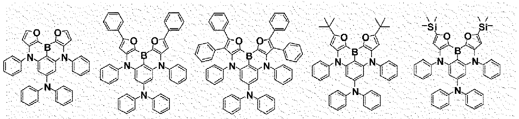
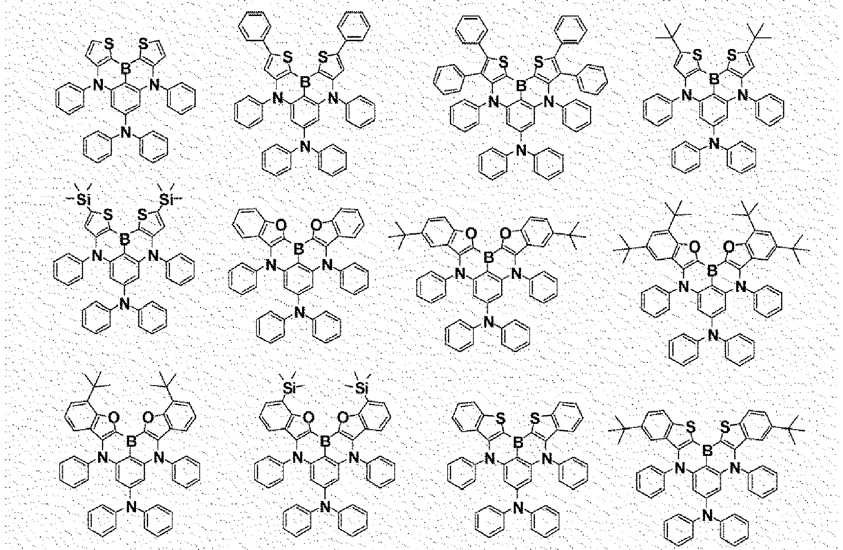




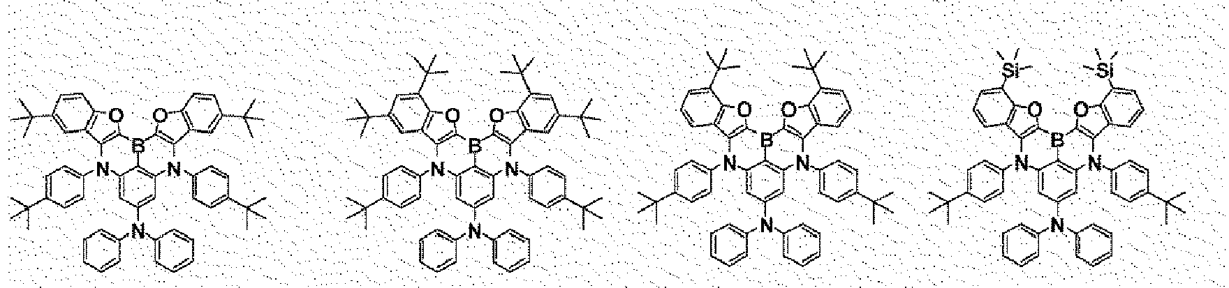


- An organic light emitting device comprising:a first electrode;a second electrode provided opposite to the first electrode; andone, two or more organic material layers provided between the first electrode and the second electrode,wherein one or more layers of the organic material layers include the heterocyclic compound of any one of Claims 1 to 6.
- The organic light emitting device of Claim 7, wherein the organic material layer includes a light emitting layer, and the light emitting layer includes the heterocyclic compound.
Applications Claiming Priority (2)
| Application Number | Priority Date | Filing Date | Title |
|---|---|---|---|
| KR20180021871 | 2018-02-23 | ||
| PCT/KR2019/002206 WO2019164331A1 (en) | 2018-02-23 | 2019-02-22 | Heterocyclic compound and organic light-emitting device comprising same |
Publications (3)
| Publication Number | Publication Date |
|---|---|
| EP3757110A1 true EP3757110A1 (en) | 2020-12-30 |
| EP3757110A4 EP3757110A4 (en) | 2021-02-17 |
| EP3757110B1 EP3757110B1 (en) | 2022-06-08 |
Family
ID=67688277
Family Applications (1)
| Application Number | Title | Priority Date | Filing Date |
|---|---|---|---|
| EP19758267.9A Active EP3757110B1 (en) | 2018-02-23 | 2019-02-22 | Heterocyclic compound and organic light-emitting device comprising same |
Country Status (6)
| Country | Link |
|---|---|
| US (1) | US11631821B2 (en) |
| EP (1) | EP3757110B1 (en) |
| JP (1) | JP6940046B2 (en) |
| KR (1) | KR102030309B1 (en) |
| CN (1) | CN111433216B (en) |
| WO (1) | WO2019164331A1 (en) |
Cited By (1)
| Publication number | Priority date | Publication date | Assignee | Title |
|---|---|---|---|---|
| EP4095216A4 (en) * | 2020-01-22 | 2024-04-03 | Hodogaya Chemical Co., Ltd. | Organic electroluminescent element |
Families Citing this family (55)
| Publication number | Priority date | Publication date | Assignee | Title |
|---|---|---|---|---|
| KR102714927B1 (en) * | 2018-09-21 | 2024-10-10 | 삼성디스플레이 주식회사 | Organic light emitting device and apparatus comprising the same |
| KR102094830B1 (en) * | 2018-11-30 | 2020-03-30 | 에스에프씨 주식회사 | Polycyclic aromatic compound and organoelectroluminescent device using the same |
| US11985891B2 (en) | 2018-11-30 | 2024-05-14 | Sfc Co., Ltd. | Polycyclic aromatic compounds and organic electroluminescent devices using the same |
| KR102858390B1 (en) * | 2019-01-11 | 2025-09-15 | 삼성디스플레이 주식회사 | Organic electroluminescence device and polycyclic compound for organic electroluminescence device |
| US12552984B2 (en) * | 2019-06-12 | 2026-02-17 | Sfc Co., Ltd. | Organic electroluminescent device |
| CN113454092B (en) | 2019-07-31 | 2024-06-14 | 株式会社Lg化学 | Compound and organic light-emitting device containing the same |
| JP7650018B2 (en) * | 2019-08-30 | 2025-03-24 | 学校法人関西学院 | Polycyclic aromatic compounds |
| US11600787B2 (en) | 2019-08-30 | 2023-03-07 | Universal Display Corporation | Organic electroluminescent materials and devices |
| US12606563B2 (en) | 2019-11-29 | 2026-04-21 | Lg Chem, Ltd. | Organic light-emitting device |
| KR20210067845A (en) | 2019-11-29 | 2021-06-08 | 주식회사 엘지화학 | Compound and organic light emitting device comprising same |
| US20220384733A1 (en) * | 2019-11-29 | 2022-12-01 | Lg Chem, Ltd. | Organic light emitting device |
| KR102477844B1 (en) * | 2019-11-29 | 2022-12-15 | 주식회사 엘지화학 | Organic light emitting device |
| WO2021107678A1 (en) | 2019-11-29 | 2021-06-03 | 주식회사 엘지화학 | Compound and organic light-emitting device comprising same |
| CN113795497B (en) * | 2019-11-29 | 2024-04-26 | 株式会社Lg化学 | Compound and organic light emitting device comprising the same |
| CN112500298B (en) * | 2019-12-27 | 2022-03-04 | 陕西莱特光电材料股份有限公司 | Arylamine compound and organic electroluminescent device |
| CN113841262A (en) * | 2020-01-20 | 2021-12-24 | 株式会社Lg化学 | Organic Light Emitting Devices |
| US12565509B2 (en) | 2020-01-22 | 2026-03-03 | Sfc Co., Ltd | Polycyclic aromatic derivative compound and organic light-emitting device using same |
| KR20210095587A (en) * | 2020-01-23 | 2021-08-02 | 에스에프씨 주식회사 | Polycyclic aromatic compound and organoelectroluminescent device using the same |
| CN113994497B (en) * | 2020-02-28 | 2024-05-31 | 株式会社Lg化学 | Organic light-emitting devices |
| WO2021172965A1 (en) * | 2020-02-28 | 2021-09-02 | 에스에프씨 주식회사 | Polycyclic aromatic derivative compound and organoelectroluminescent device using same |
| US20230138055A1 (en) * | 2020-03-03 | 2023-05-04 | Hodogaya Chemical Co., Ltd. | Organic electroluminescent device |
| JP7381770B2 (en) * | 2020-03-18 | 2023-11-16 | エスエフシー カンパニー リミテッド | Organic light emitting device using polycyclic aromatic derivative compound |
| KR102928790B1 (en) | 2020-03-19 | 2026-02-20 | 에스에프씨 주식회사 | Novel boron compound and Organic light emitting diode including the same |
| WO2021187947A1 (en) * | 2020-03-19 | 2021-09-23 | 에스에프씨 주식회사 | Organoelectroluminescent device using polycyclic aromatic compounds |
| KR20210118766A (en) * | 2020-03-23 | 2021-10-01 | 에스에프씨 주식회사 | Polycyclic aromatic compound and organoelectroluminescent device using the same |
| CN113493475B (en) * | 2020-04-07 | 2024-07-16 | 材料科学有限公司 | Organic compound and organic electroluminescent element comprising same |
| KR102331271B1 (en) * | 2020-04-07 | 2021-12-01 | 머티어리얼사이언스 주식회사 | Organic compound and organic electroluminescent device comprising the same |
| KR102302965B1 (en) * | 2020-04-14 | 2021-09-27 | 머티어리얼사이언스 주식회사 | Organic compound and organic electroluminescent device comprising the same |
| US20230159566A1 (en) * | 2020-04-16 | 2023-05-25 | Sfc Co., Ltd. | Novel boron compound and organic light-emitting diode comprising same |
| CN113666951B (en) * | 2020-05-14 | 2022-12-20 | 季华实验室 | A boron nitrogen compound, organic electroluminescent composition and organic electroluminescent device comprising same |
| KR102250355B1 (en) * | 2020-05-15 | 2021-05-11 | 머티어리얼사이언스 주식회사 | Organic compound and organic electroluminescent device comprising the same |
| JP7850660B2 (en) * | 2020-06-19 | 2026-04-23 | 保土谷化学工業株式会社 | Organic electroluminescent element |
| KR102683899B1 (en) * | 2020-06-19 | 2024-07-10 | 주식회사 엘지화학 | Organic light emitting device comprising organic compounds |
| KR20220013240A (en) * | 2020-07-24 | 2022-02-04 | 에스에프씨 주식회사 | Polycyclic aromatic compound and organoelectroluminescent device using the same |
| KR20230049656A (en) * | 2020-08-12 | 2023-04-13 | 가꼬우 호징 관세이 가쿠잉 | polycyclic aromatic compounds |
| CN114085240A (en) * | 2020-08-25 | 2022-02-25 | 广州华睿光电材料有限公司 | Organic compounds containing boron heterocycles, mixtures, compositions and organic electronic devices |
| US20230329109A1 (en) * | 2020-09-15 | 2023-10-12 | Sfc Co., Ltd. | Polycyclic aromatic derivative compound and organoelectroluminescent device using same |
| KR20220063724A (en) * | 2020-11-10 | 2022-05-17 | 에스에프씨 주식회사 | Polycyclic compound and organic light emitting device using the same |
| JP2022082867A (en) * | 2020-11-24 | 2022-06-03 | 学校法人関西学院 | Polycyclic aromatic compound |
| KR102888750B1 (en) | 2020-12-29 | 2025-11-21 | 엘지디스플레이 주식회사 | Luminescent compound and organic light emitting device having the compound |
| KR102865710B1 (en) | 2020-12-29 | 2025-09-26 | 엘지디스플레이 주식회사 | Luminescent compound and organic light emitting device having the compound |
| EP4245760B1 (en) * | 2021-01-04 | 2024-10-30 | Lg Chem, Ltd. | Novel compound and organic light-emitting device comprising same |
| KR102923907B1 (en) * | 2021-04-15 | 2026-02-04 | 주식회사 엘지화학 | Novel compound and organic light emitting device comprising the same |
| CN113045443A (en) * | 2021-04-30 | 2021-06-29 | 江西冠能光电材料有限公司 | Diaryl-ring amide compound and application thereof |
| KR102760954B1 (en) * | 2021-06-02 | 2025-01-24 | 주식회사 엘지화학 | Novel compound and organic light emitting device comprising the same |
| JP7386937B2 (en) | 2021-07-12 | 2023-11-27 | エスエフシー カンパニー リミテッド | Polycyclic compounds and organic light-emitting devices using the same |
| CN115710285A (en) * | 2021-08-18 | 2023-02-24 | 广州华睿光电材料有限公司 | Boron-containing organic compound, mixture, composition and organic electronic device |
| CN113416206B (en) * | 2021-08-23 | 2022-03-15 | 浙江华显光电科技有限公司 | Spiro compound, preparation, organic electroluminescent diode and display device |
| KR102830586B1 (en) * | 2022-04-08 | 2025-07-07 | 머티어리얼사이언스 주식회사 | Organic compounds and organic light emitting diode comprising the same |
| WO2023195828A1 (en) * | 2022-04-08 | 2023-10-12 | 머티어리얼사이언스 주식회사 | Organic compound and organic light-emitting device comprising same |
| CN114751928B (en) * | 2022-05-09 | 2024-07-05 | 吉林奥来德光电材料股份有限公司 | Polycyclic aromatic compound and preparation method thereof |
| CN117384194B (en) * | 2022-06-29 | 2025-08-01 | 江苏三月科技股份有限公司 | Boron-containing organic compound and organic electroluminescent device prepared from same |
| CN115353526B (en) * | 2022-07-05 | 2025-08-26 | 吉林奥来德光电材料股份有限公司 | A polycyclic aromatic compound and its preparation method and application |
| CN116444549B (en) * | 2022-07-19 | 2026-03-17 | 广东阿格蕾雅光电材料有限公司 | Organic electroluminescent materials and their applications |
| CN116903651B (en) * | 2023-09-07 | 2023-12-15 | 浙江华显光电科技有限公司 | Selenium-containing luminescent compound and application thereof in electronic device |
Family Cites Families (15)
| Publication number | Priority date | Publication date | Assignee | Title |
|---|---|---|---|---|
| DE10135513B4 (en) | 2001-07-20 | 2005-02-24 | Novaled Gmbh | Light-emitting component with organic layers |
| DE102009041414A1 (en) | 2009-09-16 | 2011-03-17 | Merck Patent Gmbh | metal complexes |
| WO2012115394A2 (en) | 2011-02-24 | 2012-08-30 | 덕산하이메탈(주) | Compound, organic electronic device using same, and electronic device thereof |
| TWI636056B (en) * | 2014-02-18 | 2018-09-21 | 學校法人關西學院 | Polycyclic aromatic compound and method for production the same, material for organic device and application thereof |
| US10374166B2 (en) * | 2014-02-18 | 2019-08-06 | Kwansei Gakuin Educational Foundation | Polycyclic aromatic compound |
| TWI688137B (en) * | 2015-03-24 | 2020-03-11 | 學校法人關西學院 | Organic electric field light-emitting element, display device and lighting device |
| JP6696971B2 (en) * | 2015-03-25 | 2020-05-20 | 学校法人関西学院 | Polycyclic aromatic compound and composition for forming light emitting layer |
| JP6824164B2 (en) | 2015-06-29 | 2021-02-03 | 芝浦メカトロニクス株式会社 | Tablet printing device and tablet printing method |
| KR20250078582A (en) * | 2016-02-10 | 2025-06-02 | 가꼬우 호징 관세이 가쿠잉 | Delayed fluorescent organic electric field light-emitting element |
| KR20220084200A (en) * | 2016-04-26 | 2022-06-21 | 가꼬우 호징 관세이 가쿠잉 | Organic Electroluminescence Device |
| KR102672246B1 (en) * | 2016-07-13 | 2024-06-07 | 삼성디스플레이 주식회사 | Polycyclic compound and organic electroluminescence device including the same |
| CN107501311A (en) | 2017-07-14 | 2017-12-22 | 瑞声科技(南京)有限公司 | Electroluminescent organic material and its luminescent device |
| US11637249B2 (en) * | 2017-08-17 | 2023-04-25 | Kwansei Gakuin Educational Foundation | Organic electroluminescent element |
| KR102618236B1 (en) * | 2017-12-11 | 2023-12-26 | 가꼬우 호징 관세이 가쿠잉 | Deuterium substituted polycyclic aromatic compound |
| US11342506B2 (en) * | 2018-06-20 | 2022-05-24 | Kwansei Gakuin Educational Foundation | Organic electroluminescent element |
-
2019
- 2019-02-22 WO PCT/KR2019/002206 patent/WO2019164331A1/en not_active Ceased
- 2019-02-22 JP JP2020528894A patent/JP6940046B2/en active Active
- 2019-02-22 EP EP19758267.9A patent/EP3757110B1/en active Active
- 2019-02-22 US US16/771,361 patent/US11631821B2/en active Active
- 2019-02-22 KR KR1020190021088A patent/KR102030309B1/en active Active
- 2019-02-22 CN CN201980006178.8A patent/CN111433216B/en active Active
Cited By (1)
| Publication number | Priority date | Publication date | Assignee | Title |
|---|---|---|---|---|
| EP4095216A4 (en) * | 2020-01-22 | 2024-04-03 | Hodogaya Chemical Co., Ltd. | Organic electroluminescent element |
Also Published As
| Publication number | Publication date |
|---|---|
| CN111433216B (en) | 2023-07-18 |
| CN111433216A (en) | 2020-07-17 |
| KR20190101900A (en) | 2019-09-02 |
| US11631821B2 (en) | 2023-04-18 |
| EP3757110B1 (en) | 2022-06-08 |
| WO2019164331A1 (en) | 2019-08-29 |
| US20210184121A1 (en) | 2021-06-17 |
| EP3757110A4 (en) | 2021-02-17 |
| JP6940046B2 (en) | 2021-09-22 |
| KR102030309B1 (en) | 2019-10-08 |
| JP2021504373A (en) | 2021-02-15 |
Similar Documents
| Publication | Publication Date | Title |
|---|---|---|
| EP3757110B1 (en) | Heterocyclic compound and organic light-emitting device comprising same | |
| EP3767694B1 (en) | Organic light-emitting device | |
| EP3305771B1 (en) | Organic light emitting device including a heterocyclic compound | |
| EP3862350B1 (en) | Novel compound and organic light emitting device using same | |
| EP3336159A1 (en) | Organic light-emitting element | |
| EP3439062A1 (en) | Organic light emitting element | |
| EP3002282A1 (en) | Hetero ring compound and organic light emitting diode comprising same | |
| EP3428163A1 (en) | Polycyclic compound and organic light emitting element comprising same | |
| JP7512556B2 (en) | Novel compound and organic light-emitting device using the same | |
| EP3767695A1 (en) | Organic light-emitting device | |
| EP3345891A1 (en) | Amine compound and organic light-emitting device comprising same | |
| KR102207385B1 (en) | Heterocyclic compound and organic light emitting device comprising the same | |
| EP3483152A1 (en) | Compound and organic light-emitting device comprising same | |
| EP3369718B1 (en) | Spiro-type compound and organic light emitting element comprising same | |
| EP3263555B1 (en) | Hetero ring compound and organic luminescent element comprising same | |
| KR102262698B1 (en) | Hetero cyclic compound and organic light emitting device comprising the same | |
| CN113166112A (en) | Novel compound and organic light emitting device comprising same | |
| KR102546268B1 (en) | Novel compound and organic light emitting device comprising the same | |
| EP3369719B1 (en) | Spiro-type compound and organic light emitting element comprising same | |
| KR102592082B1 (en) | Novel compound and organic light emitting device comprising the same | |
| CN114144402A (en) | Novel compound and organic light emitting device comprising same | |
| CN111770920B (en) | Compound and organic light emitting device comprising the same | |
| JP2017521366A (en) | Heterocyclic compound and organic light emitting device including the same | |
| CN114097103A (en) | Organic light emitting device | |
| CN112105613B (en) | Compounds and organic light-emitting devices containing the same |
Legal Events
| Date | Code | Title | Description |
|---|---|---|---|
| STAA | Information on the status of an ep patent application or granted ep patent |
Free format text: STATUS: THE INTERNATIONAL PUBLICATION HAS BEEN MADE |
|
| PUAI | Public reference made under article 153(3) epc to a published international application that has entered the european phase |
Free format text: ORIGINAL CODE: 0009012 |
|
| STAA | Information on the status of an ep patent application or granted ep patent |
Free format text: STATUS: REQUEST FOR EXAMINATION WAS MADE |
|
| 17P | Request for examination filed |
Effective date: 20200525 |
|
| AK | Designated contracting states |
Kind code of ref document: A1 Designated state(s): AL AT BE BG CH CY CZ DE DK EE ES FI FR GB GR HR HU IE IS IT LI LT LU LV MC MK MT NL NO PL PT RO RS SE SI SK SM TR |
|
| AX | Request for extension of the european patent |
Extension state: BA ME |
|
| A4 | Supplementary search report drawn up and despatched |
Effective date: 20210119 |
|
| RIC1 | Information provided on ipc code assigned before grant |
Ipc: C09K 11/06 20060101ALI20210113BHEP Ipc: H01L 51/50 20060101ALI20210113BHEP Ipc: H01L 51/00 20060101ALI20210113BHEP Ipc: C07F 5/02 20060101AFI20210113BHEP |
|
| DAV | Request for validation of the european patent (deleted) | ||
| DAX | Request for extension of the european patent (deleted) | ||
| STAA | Information on the status of an ep patent application or granted ep patent |
Free format text: STATUS: EXAMINATION IS IN PROGRESS |
|
| 17Q | First examination report despatched |
Effective date: 20211021 |
|
| GRAP | Despatch of communication of intention to grant a patent |
Free format text: ORIGINAL CODE: EPIDOSNIGR1 |
|
| STAA | Information on the status of an ep patent application or granted ep patent |
Free format text: STATUS: GRANT OF PATENT IS INTENDED |
|
| GRAS | Grant fee paid |
Free format text: ORIGINAL CODE: EPIDOSNIGR3 |
|
| INTG | Intention to grant announced |
Effective date: 20220406 |
|
| GRAA | (expected) grant |
Free format text: ORIGINAL CODE: 0009210 |
|
| STAA | Information on the status of an ep patent application or granted ep patent |
Free format text: STATUS: THE PATENT HAS BEEN GRANTED |
|
| AK | Designated contracting states |
Kind code of ref document: B1 Designated state(s): AL AT BE BG CH CY CZ DE DK EE ES FI FR GB GR HR HU IE IS IT LI LT LU LV MC MK MT NL NO PL PT RO RS SE SI SK SM TR |
|
| REG | Reference to a national code |
Ref country code: AT Ref legal event code: REF Ref document number: 1496866 Country of ref document: AT Kind code of ref document: T Effective date: 20220615 Ref country code: CH Ref legal event code: EP |
|
| REG | Reference to a national code |
Ref country code: DE Ref legal event code: R096 Ref document number: 602019015735 Country of ref document: DE |
|
| REG | Reference to a national code |
Ref country code: IE Ref legal event code: FG4D |
|
| REG | Reference to a national code |
Ref country code: LT Ref legal event code: MG9D |
|
| REG | Reference to a national code |
Ref country code: NL Ref legal event code: MP Effective date: 20220608 |
|
| PG25 | Lapsed in a contracting state [announced via postgrant information from national office to epo] |
Ref country code: SE Free format text: LAPSE BECAUSE OF FAILURE TO SUBMIT A TRANSLATION OF THE DESCRIPTION OR TO PAY THE FEE WITHIN THE PRESCRIBED TIME-LIMIT Effective date: 20220608 Ref country code: NO Free format text: LAPSE BECAUSE OF FAILURE TO SUBMIT A TRANSLATION OF THE DESCRIPTION OR TO PAY THE FEE WITHIN THE PRESCRIBED TIME-LIMIT Effective date: 20220908 Ref country code: LT Free format text: LAPSE BECAUSE OF FAILURE TO SUBMIT A TRANSLATION OF THE DESCRIPTION OR TO PAY THE FEE WITHIN THE PRESCRIBED TIME-LIMIT Effective date: 20220608 Ref country code: HR Free format text: LAPSE BECAUSE OF FAILURE TO SUBMIT A TRANSLATION OF THE DESCRIPTION OR TO PAY THE FEE WITHIN THE PRESCRIBED TIME-LIMIT Effective date: 20220608 Ref country code: GR Free format text: LAPSE BECAUSE OF FAILURE TO SUBMIT A TRANSLATION OF THE DESCRIPTION OR TO PAY THE FEE WITHIN THE PRESCRIBED TIME-LIMIT Effective date: 20220909 Ref country code: FI Free format text: LAPSE BECAUSE OF FAILURE TO SUBMIT A TRANSLATION OF THE DESCRIPTION OR TO PAY THE FEE WITHIN THE PRESCRIBED TIME-LIMIT Effective date: 20220608 Ref country code: BG Free format text: LAPSE BECAUSE OF FAILURE TO SUBMIT A TRANSLATION OF THE DESCRIPTION OR TO PAY THE FEE WITHIN THE PRESCRIBED TIME-LIMIT Effective date: 20220908 |
|
| REG | Reference to a national code |
Ref country code: AT Ref legal event code: MK05 Ref document number: 1496866 Country of ref document: AT Kind code of ref document: T Effective date: 20220608 |
|
| PG25 | Lapsed in a contracting state [announced via postgrant information from national office to epo] |
Ref country code: RS Free format text: LAPSE BECAUSE OF FAILURE TO SUBMIT A TRANSLATION OF THE DESCRIPTION OR TO PAY THE FEE WITHIN THE PRESCRIBED TIME-LIMIT Effective date: 20220608 Ref country code: LV Free format text: LAPSE BECAUSE OF FAILURE TO SUBMIT A TRANSLATION OF THE DESCRIPTION OR TO PAY THE FEE WITHIN THE PRESCRIBED TIME-LIMIT Effective date: 20220608 |
|
| PG25 | Lapsed in a contracting state [announced via postgrant information from national office to epo] |
Ref country code: NL Free format text: LAPSE BECAUSE OF FAILURE TO SUBMIT A TRANSLATION OF THE DESCRIPTION OR TO PAY THE FEE WITHIN THE PRESCRIBED TIME-LIMIT Effective date: 20220608 |
|
| PG25 | Lapsed in a contracting state [announced via postgrant information from national office to epo] |
Ref country code: SM Free format text: LAPSE BECAUSE OF FAILURE TO SUBMIT A TRANSLATION OF THE DESCRIPTION OR TO PAY THE FEE WITHIN THE PRESCRIBED TIME-LIMIT Effective date: 20220608 Ref country code: SK Free format text: LAPSE BECAUSE OF FAILURE TO SUBMIT A TRANSLATION OF THE DESCRIPTION OR TO PAY THE FEE WITHIN THE PRESCRIBED TIME-LIMIT Effective date: 20220608 Ref country code: RO Free format text: LAPSE BECAUSE OF FAILURE TO SUBMIT A TRANSLATION OF THE DESCRIPTION OR TO PAY THE FEE WITHIN THE PRESCRIBED TIME-LIMIT Effective date: 20220608 Ref country code: PT Free format text: LAPSE BECAUSE OF FAILURE TO SUBMIT A TRANSLATION OF THE DESCRIPTION OR TO PAY THE FEE WITHIN THE PRESCRIBED TIME-LIMIT Effective date: 20221010 Ref country code: ES Free format text: LAPSE BECAUSE OF FAILURE TO SUBMIT A TRANSLATION OF THE DESCRIPTION OR TO PAY THE FEE WITHIN THE PRESCRIBED TIME-LIMIT Effective date: 20220608 Ref country code: EE Free format text: LAPSE BECAUSE OF FAILURE TO SUBMIT A TRANSLATION OF THE DESCRIPTION OR TO PAY THE FEE WITHIN THE PRESCRIBED TIME-LIMIT Effective date: 20220608 Ref country code: CZ Free format text: LAPSE BECAUSE OF FAILURE TO SUBMIT A TRANSLATION OF THE DESCRIPTION OR TO PAY THE FEE WITHIN THE PRESCRIBED TIME-LIMIT Effective date: 20220608 Ref country code: AT Free format text: LAPSE BECAUSE OF FAILURE TO SUBMIT A TRANSLATION OF THE DESCRIPTION OR TO PAY THE FEE WITHIN THE PRESCRIBED TIME-LIMIT Effective date: 20220608 |
|
| PG25 | Lapsed in a contracting state [announced via postgrant information from national office to epo] |
Ref country code: PL Free format text: LAPSE BECAUSE OF FAILURE TO SUBMIT A TRANSLATION OF THE DESCRIPTION OR TO PAY THE FEE WITHIN THE PRESCRIBED TIME-LIMIT Effective date: 20220608 Ref country code: IS Free format text: LAPSE BECAUSE OF FAILURE TO SUBMIT A TRANSLATION OF THE DESCRIPTION OR TO PAY THE FEE WITHIN THE PRESCRIBED TIME-LIMIT Effective date: 20221008 |
|
| REG | Reference to a national code |
Ref country code: DE Ref legal event code: R097 Ref document number: 602019015735 Country of ref document: DE |
|
| PG25 | Lapsed in a contracting state [announced via postgrant information from national office to epo] |
Ref country code: AL Free format text: LAPSE BECAUSE OF FAILURE TO SUBMIT A TRANSLATION OF THE DESCRIPTION OR TO PAY THE FEE WITHIN THE PRESCRIBED TIME-LIMIT Effective date: 20220608 |
|
| PLBE | No opposition filed within time limit |
Free format text: ORIGINAL CODE: 0009261 |
|
| STAA | Information on the status of an ep patent application or granted ep patent |
Free format text: STATUS: NO OPPOSITION FILED WITHIN TIME LIMIT |
|
| PG25 | Lapsed in a contracting state [announced via postgrant information from national office to epo] |
Ref country code: DK Free format text: LAPSE BECAUSE OF FAILURE TO SUBMIT A TRANSLATION OF THE DESCRIPTION OR TO PAY THE FEE WITHIN THE PRESCRIBED TIME-LIMIT Effective date: 20220608 |
|
| 26N | No opposition filed |
Effective date: 20230310 |
|
| PG25 | Lapsed in a contracting state [announced via postgrant information from national office to epo] |
Ref country code: SI Free format text: LAPSE BECAUSE OF FAILURE TO SUBMIT A TRANSLATION OF THE DESCRIPTION OR TO PAY THE FEE WITHIN THE PRESCRIBED TIME-LIMIT Effective date: 20220608 |
|
| PG25 | Lapsed in a contracting state [announced via postgrant information from national office to epo] |
Ref country code: MC Free format text: LAPSE BECAUSE OF FAILURE TO SUBMIT A TRANSLATION OF THE DESCRIPTION OR TO PAY THE FEE WITHIN THE PRESCRIBED TIME-LIMIT Effective date: 20220608 |
|
| REG | Reference to a national code |
Ref country code: CH Ref legal event code: PL |
|
| REG | Reference to a national code |
Ref country code: BE Ref legal event code: MM Effective date: 20230228 |
|
| PG25 | Lapsed in a contracting state [announced via postgrant information from national office to epo] |
Ref country code: LU Free format text: LAPSE BECAUSE OF NON-PAYMENT OF DUE FEES Effective date: 20230222 Ref country code: LI Free format text: LAPSE BECAUSE OF NON-PAYMENT OF DUE FEES Effective date: 20230228 Ref country code: CH Free format text: LAPSE BECAUSE OF NON-PAYMENT OF DUE FEES Effective date: 20230228 |
|
| REG | Reference to a national code |
Ref country code: IE Ref legal event code: MM4A |
|
| PG25 | Lapsed in a contracting state [announced via postgrant information from national office to epo] |
Ref country code: IT Free format text: LAPSE BECAUSE OF FAILURE TO SUBMIT A TRANSLATION OF THE DESCRIPTION OR TO PAY THE FEE WITHIN THE PRESCRIBED TIME-LIMIT Effective date: 20220608 Ref country code: IE Free format text: LAPSE BECAUSE OF NON-PAYMENT OF DUE FEES Effective date: 20230222 |
|
| PG25 | Lapsed in a contracting state [announced via postgrant information from national office to epo] |
Ref country code: BE Free format text: LAPSE BECAUSE OF NON-PAYMENT OF DUE FEES Effective date: 20230228 |
|
| PG25 | Lapsed in a contracting state [announced via postgrant information from national office to epo] |
Ref country code: BG Free format text: LAPSE BECAUSE OF FAILURE TO SUBMIT A TRANSLATION OF THE DESCRIPTION OR TO PAY THE FEE WITHIN THE PRESCRIBED TIME-LIMIT Effective date: 20220608 |
|
| PG25 | Lapsed in a contracting state [announced via postgrant information from national office to epo] |
Ref country code: BG Free format text: LAPSE BECAUSE OF FAILURE TO SUBMIT A TRANSLATION OF THE DESCRIPTION OR TO PAY THE FEE WITHIN THE PRESCRIBED TIME-LIMIT Effective date: 20220608 |
|
| PG25 | Lapsed in a contracting state [announced via postgrant information from national office to epo] |
Ref country code: CY Free format text: LAPSE BECAUSE OF FAILURE TO SUBMIT A TRANSLATION OF THE DESCRIPTION OR TO PAY THE FEE WITHIN THE PRESCRIBED TIME-LIMIT; INVALID AB INITIO Effective date: 20190222 |
|
| PG25 | Lapsed in a contracting state [announced via postgrant information from national office to epo] |
Ref country code: HU Free format text: LAPSE BECAUSE OF FAILURE TO SUBMIT A TRANSLATION OF THE DESCRIPTION OR TO PAY THE FEE WITHIN THE PRESCRIBED TIME-LIMIT; INVALID AB INITIO Effective date: 20190222 |
|
| PG25 | Lapsed in a contracting state [announced via postgrant information from national office to epo] |
Ref country code: TR Free format text: LAPSE BECAUSE OF FAILURE TO SUBMIT A TRANSLATION OF THE DESCRIPTION OR TO PAY THE FEE WITHIN THE PRESCRIBED TIME-LIMIT Effective date: 20220608 |
|
| PGFP | Annual fee paid to national office [announced via postgrant information from national office to epo] |
Ref country code: GB Payment date: 20260122 Year of fee payment: 8 |
|
| PGFP | Annual fee paid to national office [announced via postgrant information from national office to epo] |
Ref country code: DE Payment date: 20260120 Year of fee payment: 8 |
|
| PGFP | Annual fee paid to national office [announced via postgrant information from national office to epo] |
Ref country code: FR Payment date: 20260121 Year of fee payment: 8 |