EP3757007A1 - Systems and methods for sealing a refrigerated galley of an aircraft - Google Patents
Systems and methods for sealing a refrigerated galley of an aircraft Download PDFInfo
- Publication number
- EP3757007A1 EP3757007A1 EP20175135.1A EP20175135A EP3757007A1 EP 3757007 A1 EP3757007 A1 EP 3757007A1 EP 20175135 A EP20175135 A EP 20175135A EP 3757007 A1 EP3757007 A1 EP 3757007A1
- Authority
- EP
- European Patent Office
- Prior art keywords
- seal
- housing
- door
- coupled
- galley
- Prior art date
- Legal status (The legal status is an assumption and is not a legal conclusion. Google has not performed a legal analysis and makes no representation as to the accuracy of the status listed.)
- Granted
Links
Images




Classifications
-
- F—MECHANICAL ENGINEERING; LIGHTING; HEATING; WEAPONS; BLASTING
- F25—REFRIGERATION OR COOLING; COMBINED HEATING AND REFRIGERATION SYSTEMS; HEAT PUMP SYSTEMS; MANUFACTURE OR STORAGE OF ICE; LIQUEFACTION SOLIDIFICATION OF GASES
- F25D—REFRIGERATORS; COLD ROOMS; ICE-BOXES; COOLING OR FREEZING APPARATUS NOT OTHERWISE PROVIDED FOR
- F25D23/00—General constructional features
- F25D23/08—Parts formed wholly or mainly of plastics materials
- F25D23/082—Strips
- F25D23/087—Sealing strips
-
- B—PERFORMING OPERATIONS; TRANSPORTING
- B64—AIRCRAFT; AVIATION; COSMONAUTICS
- B64D—EQUIPMENT FOR FITTING IN OR TO AIRCRAFT; FLIGHT SUITS; PARACHUTES; ARRANGEMENT OR MOUNTING OF POWER PLANTS OR PROPULSION TRANSMISSIONS IN AIRCRAFT
- B64D11/00—Passenger or crew accommodation; Flight-deck installations not otherwise provided for
- B64D11/04—Galleys
-
- B—PERFORMING OPERATIONS; TRANSPORTING
- B64—AIRCRAFT; AVIATION; COSMONAUTICS
- B64D—EQUIPMENT FOR FITTING IN OR TO AIRCRAFT; FLIGHT SUITS; PARACHUTES; ARRANGEMENT OR MOUNTING OF POWER PLANTS OR PROPULSION TRANSMISSIONS IN AIRCRAFT
- B64D11/00—Passenger or crew accommodation; Flight-deck installations not otherwise provided for
- B64D11/0007—Devices specially adapted for food or beverage distribution services
-
- E—FIXED CONSTRUCTIONS
- E06—DOORS, WINDOWS, SHUTTERS, OR ROLLER BLINDS IN GENERAL; LADDERS
- E06B—FIXED OR MOVABLE CLOSURES FOR OPENINGS IN BUILDINGS, VEHICLES, FENCES OR LIKE ENCLOSURES IN GENERAL, e.g. DOORS, WINDOWS, BLINDS, GATES
- E06B7/00—Special arrangements or measures in connection with doors or windows
- E06B7/16—Sealing arrangements on wings or parts co-operating with the wings
- E06B7/18—Sealing arrangements on wings or parts co-operating with the wings by means of movable edgings, e.g. draught sealings additionally used for bolting, e.g. by spring force or with operating lever
- E06B7/20—Sealing arrangements on wings or parts co-operating with the wings by means of movable edgings, e.g. draught sealings additionally used for bolting, e.g. by spring force or with operating lever automatically withdrawn when the wing is opened, e.g. by means of magnetic attraction, a pin or an inclined surface, especially for sills
- E06B7/21—Sealing arrangements on wings or parts co-operating with the wings by means of movable edgings, e.g. draught sealings additionally used for bolting, e.g. by spring force or with operating lever automatically withdrawn when the wing is opened, e.g. by means of magnetic attraction, a pin or an inclined surface, especially for sills with sealing strip movable in plane of wing
-
- E—FIXED CONSTRUCTIONS
- E06—DOORS, WINDOWS, SHUTTERS, OR ROLLER BLINDS IN GENERAL; LADDERS
- E06B—FIXED OR MOVABLE CLOSURES FOR OPENINGS IN BUILDINGS, VEHICLES, FENCES OR LIKE ENCLOSURES IN GENERAL, e.g. DOORS, WINDOWS, BLINDS, GATES
- E06B7/00—Special arrangements or measures in connection with doors or windows
- E06B7/16—Sealing arrangements on wings or parts co-operating with the wings
- E06B7/18—Sealing arrangements on wings or parts co-operating with the wings by means of movable edgings, e.g. draught sealings additionally used for bolting, e.g. by spring force or with operating lever
- E06B7/20—Sealing arrangements on wings or parts co-operating with the wings by means of movable edgings, e.g. draught sealings additionally used for bolting, e.g. by spring force or with operating lever automatically withdrawn when the wing is opened, e.g. by means of magnetic attraction, a pin or an inclined surface, especially for sills
- E06B7/215—Sealing arrangements on wings or parts co-operating with the wings by means of movable edgings, e.g. draught sealings additionally used for bolting, e.g. by spring force or with operating lever automatically withdrawn when the wing is opened, e.g. by means of magnetic attraction, a pin or an inclined surface, especially for sills with sealing strip being moved to a retracted position by elastic means, e.g. springs
-
- F—MECHANICAL ENGINEERING; LIGHTING; HEATING; WEAPONS; BLASTING
- F25—REFRIGERATION OR COOLING; COMBINED HEATING AND REFRIGERATION SYSTEMS; HEAT PUMP SYSTEMS; MANUFACTURE OR STORAGE OF ICE; LIQUEFACTION SOLIDIFICATION OF GASES
- F25D—REFRIGERATORS; COLD ROOMS; ICE-BOXES; COOLING OR FREEZING APPARATUS NOT OTHERWISE PROVIDED FOR
- F25D23/00—General constructional features
- F25D23/02—Doors; Covers
- F25D23/028—Details
-
- E—FIXED CONSTRUCTIONS
- E06—DOORS, WINDOWS, SHUTTERS, OR ROLLER BLINDS IN GENERAL; LADDERS
- E06B—FIXED OR MOVABLE CLOSURES FOR OPENINGS IN BUILDINGS, VEHICLES, FENCES OR LIKE ENCLOSURES IN GENERAL, e.g. DOORS, WINDOWS, BLINDS, GATES
- E06B7/00—Special arrangements or measures in connection with doors or windows
- E06B7/16—Sealing arrangements on wings or parts co-operating with the wings
- E06B7/18—Sealing arrangements on wings or parts co-operating with the wings by means of movable edgings, e.g. draught sealings additionally used for bolting, e.g. by spring force or with operating lever
- E06B7/20—Sealing arrangements on wings or parts co-operating with the wings by means of movable edgings, e.g. draught sealings additionally used for bolting, e.g. by spring force or with operating lever automatically withdrawn when the wing is opened, e.g. by means of magnetic attraction, a pin or an inclined surface, especially for sills
- E06B2007/202—Actuator connected to wing frame
-
- F—MECHANICAL ENGINEERING; LIGHTING; HEATING; WEAPONS; BLASTING
- F25—REFRIGERATION OR COOLING; COMBINED HEATING AND REFRIGERATION SYSTEMS; HEAT PUMP SYSTEMS; MANUFACTURE OR STORAGE OF ICE; LIQUEFACTION SOLIDIFICATION OF GASES
- F25D—REFRIGERATORS; COLD ROOMS; ICE-BOXES; COOLING OR FREEZING APPARATUS NOT OTHERWISE PROVIDED FOR
- F25D2323/00—General constructional features not provided for in other groups of this subclass
- F25D2323/02—Details of doors or covers not otherwise covered
Definitions
- the present disclosure relates generally to a system for sealing a refrigerated compartment, and more particularly, to a system to lift a seal positioned on a bottom surface of a door when the door is opened to prevent the seal from dragging along the floor surface when the door is opened.
- Aircraft galley cart compartments are often refrigerated to keep the contents therein cold.
- Traditional galley doors in such refrigerated sections use seals to keep the compartment cold.
- the doors extend to the floor surface, and the seal is positioned along the bottom surface of the door and contacts the floor surface.
- Existing seals on traditional galley doors may be more accurately described as close-outs.
- Such seals are typically "whisker brush” devices that allow air flow thru the whiskers and additionally are not fully sealed against the floor surface due to their inability to flex and conform to the floor surface. Further, such a seal is prone to wear and tear as the door is opened and closed as such actions cause the seal to drag along the floor surface. Eventually the seal is replaced during maintenance as it becomes worn.
- a worn seal Prior to replacement, a worn seal may enable cooled air to leak from the enclosed galley cart compartment, causing the airplane environmental control systems to work harder than necessary to maintain the appropriate temperature. As such, a need exists for a seal system for the bottom surface of the galley door that has an extended life and improved thermal sealing characteristics.
- the present disclosure provides a system for sealing a refrigerated galley of an aircraft.
- the system includes (a) a door having a top surface, a bottom surface opposite the top surface, a first side surface, and a second side surface opposite the first side surface, and (b) a seal assembly positioned at the bottom surface of the door.
- the seal assembly includes (i) a housing coupled to the bottom surface of the door, (ii) a seal positioned at least partially in the housing, wherein the seal is moveable relative to the housing and the door, (iii) a biasing mechanism coupled to the housing and the seal, wherein the biasing mechanism is configured to hold the seal in a relaxed state by applying a biasing force to the seal in a direction away from a floor surface of the refrigerated galley, and (iv) an activation mechanism coupled to the housing, wherein the activation mechanism is configured to transition the seal from the relaxed state to a compressed state in response to a rotation of the door from an open position to a closed position, wherein a height of the seal is greater in the relaxed state than in the compressed state.
- the present disclosure provides a galley for an aircraft.
- the galley includes (a) a refrigerated cart compartment, (b) a door frame defining a front wall of the refrigerated cart compartment, (c) a door coupled to the door frame at a hinge, the door having a top surface, a bottom surface opposite the top surface, a first side surface, and a second side surface opposite the first side surface, and (d) a seal assembly positioned at the bottom surface of the door.
- the seal assembly includes (i) a housing coupled to the bottom surface of the door, (ii) a seal positioned at least partially in the housing, wherein the seal is moveable relative to the housing and the door, (iii) a biasing mechanism coupled to the housing and the seal, wherein the biasing mechanism is configured to hold the seal in a relaxed state by applying a biasing force to the seal in a direction away from a floor surface of the galley, and (iv) an activation mechanism coupled to the housing, wherein the activation mechanism is configured to transition the seal from the relaxed state to a compressed state in response to a rotation of the door from an open position to a closed position, wherein a height of the seal is greater in the relaxed state than in the compressed state.
- the present disclosure provides a method of assembling an aircraft galley with a seal assembly including a housing, a seal coupled to the housing, and a biasing mechanism coupled to the housing.
- the method includes coupling a door to a door frame above a floor surface of the aircraft galley to close a galley cart compartment, wherein the door rotates from a closed position to an open position.
- the method also includes coupling the housing to a bottom surface of the door such that the seal is configured to contact the floor surface when the door is in the closed position.
- the method also includes coupling the biasing mechanism to the door and to the housing to hold the seal in a relaxed state by applying a biasing force to the seal in a direction away from the floor surface.
- the method also includes coupling an activation mechanism proximate to the door frame to interact with the housing to overcome the biasing force to transition the seal from the relaxed state to a compressed state in response to a rotation of the door from the open position to the closed position to thereby seal the aircraft galley, wherein a height of the seal is greater in the relaxed state than in the compressed state.
- a seal assembly for a galley is provided for an aircraft that seals against a sealing surface of the galley, which may be against the floor or against another surface, such as part of the door frame of the galley.
- the seal at the seal edge is configured to seal against the door frame between the floor and the bottom of the door to prevent side leakage.
- the seal is movable to a relaxed state and held in the relaxed state as the door is opened and closed to prevent damage and wear to the seal.
- the seal is movably coupled to the door and moved between the relaxed state and a compressed state in which the seal contacts the sealing surface of the galley.
- the seal is movably coupled to the door frame and moved between the relaxed state and the compressed state, such as by the opening and closing action of the door.
- a more compliant seal can be used, which provides better, more efficient sealing than conventional blade seals or brush seals because the seal is not subjected to wear and tear during opening and closing of the door.
- Various embodiments of the seal assembly provide a biasing mechanism to hold the seal in the relaxed state and an activation mechanism to transition the seal to the compressed state when the door is closed.
- the activation mechanism automatically closes the seal by closing the door and automatically opens the seal by opening the door.
- FIG 1 is a schematic illustration of an exemplary system 100 for an aircraft 106.
- the system 100 is used to cool galley carts 108 held in cart compartments 102 of a galley 104.
- the galley 104 defines one or more cart compartments 102, which are typically arranged below a counter 105 of the galley 104.
- the cart compartments 102 are closed by doors 132 having seal assemblies 140 for sealing the cart compartments 102, such as at the floor surface and/or around the door frames.
- Each cart compartment 102 may hold any number of galley carts 108.
- the galley 104 may be used for the storage and/or preparation of food or beverages.
- the galley 104 is positioned within a cabin 110 of the aircraft 106, and the cabin of the aircraft 106 is divided into a passenger area 112 and a galley area 114.
- the galley area 114 has a working area for the galley crew forward of the galley 104 where the cart compartments 102, counter 105 and cabinets or storage bins may be accessed.
- a “cart compartment” is an insulated volume that is utilized to store one or more galley carts on the aircraft 106.
- a "galley cart”, as used herein, is a portable device that is used to store food and/or beverages that are transported from a caterer to the aircraft 106 or from the cart compartments 102 to other parts of the aircraft 106 for serving the food and/or beverages.
- the galley carts may include wheels, however some galley carts may be hand carried boxes in some embodiments.
- the system 100 includes a cooling system having one or more heat exchangers 116 that provides cooled air for the galley carts 108 in the cart compartment 102.
- the cooled air from the heat exchangers 116 flows into and out of the cart compartments 102 through supply or return ducts in the rear wall of the galley 104.
- FIG 2 is a side view of the galley 104 in accordance with an exemplary embodiment.
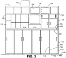
- Figure 3 is a front view of the galley 104 in accordance with an exemplary embodiment.
- the galley 104 includes walls 118 or partitions defining a floor surface 120, a top 122, a front 124, a rear 126 opposite the front 124, and opposite sides 128, 129 (which may also be referred to as floor surface 120, top wall 122, front wall 124, rear wall 126, and side walls 128, 129).
- the counter 105 extends between the sides 128, 129 at a height approximately centered between the floor surface 120 and the top 122.
- the floor surface 120 may be the bottom or bottom wall of the galley 104, for example.
- the cart compartment 102 is positioned below the counter 105 and may be at least partially defined by the walls 118 of the galley 104.
- the cart compartment 102 defines a chamber 130 configured to receive the galley carts 108.
- the doors 132 are provided at the front 124 of the galley 104 and close the cart compartment 102.
- the doors 132 are received in door frames 134 and, in the illustrated embodiment, are hingedly coupled to the door frames 134 at one of the first side surface 136 or the second side surface 137 of the corresponding door 132.
- the doors 132 are used to hold the galley carts 108 in the cart compartment 102.
- the doors 132 are also used to contain the cooled air in the cart compartment 102, and may further provide thermal insulation.
- a bottom surface 138 of each door 132 faces the floor surface 120.
- a space is defined about the galley cart 108, such as in front of the galley carts 108, behind the galley carts 108, above the galley carts 108, and the like to allow air to flow around the galley carts 108 in the space.
- the galley 104 includes a seal assembly 140 on each door 132 for sealing the cart compartment 102.
- the seal assembly 140 is provided at the bottom surface 138 of the door 132 to seal between the bottom surface 138 of the door and the floor surface 120.
- the seal assembly 140 may additionally or alternatively be provided at other areas of the door 132, such as along the first side surface 136, the second side surface 137, or a top surface 139 of the door 132.
- multiple seal assemblies 140 may be provided to seal against multiple surfaces.
- the seal assembly 140 may be coupled to the door frame 134 rather than the door 132 to seal between the door frame 134 and the door 132, such as at the space between the bottom surface 138 of the door 132 and the floor surface 120.
- Figure 4 is a front view of a portion of the galley 104 showing the door 132 in a closed position illustrating the seal assembly 140 in a compressed state between the bottom surface 138 of the door 132 and the floor surface 120.
- the seal assembly 140 includes a seal 142 configured to be movably coupled to the door 132 and a housing 144 holding the seal 142.
- the housing 144 may be coupled to the bottom surface 138 of the door 132, and the seal 142 is positioned at least partially in the housing 144.
- the seal 142 is removably positioned in the housing 144. Such an embodiment may provide easy cleaning of the seal 142 and/or replacement of the seal 142 as necessary.
- the seal assembly 140 includes at least one biasing mechanism 146 coupled to the housing 144 and the seal 142 and configured to hold the seal 142 in a relaxed state by applying a biasing force to the seal 142 in a direction away from the floor surface 120 of the galley 104.
- the seal assembly 140 includes at least one activation mechanism 148 operably engaging the housing 144 to hold the seal 142 in the compressed state.
- the biasing mechanism 146 is configured to hold the seal 142 in the relaxed state by applying a biasing force to the housing 144.
- the biasing mechanism 146 may open the seal assembly 140 prior to opening the door 132 or simultaneously as the door 132 is being opened.
- the activation mechanism 148 is configured to overcome the biasing force to transition the seal 142 from the relaxed state to the compressed state in response to a rotation of the door 132 from an open position to a closed position, or simultaneously as the door 132 is being closed, such as immediately before the door 132 is moved to the closed position.
- the activation mechanism 148 may be used to move the seal 142 to the compressed state.
- the seal assembly 140 is provided at the bottom surface 138 of the door 132 and closes off a space 150 between the bottom surface 138 of the door 132 and the floor surface 120.
- at least a portion of the housing 144 may extend into the door 132 and at least a portion of the housing 144 may extend below the bottom surface 138 of the door 132.
- the seal 142 is provided at the bottom of the housing 144.
- the seal 142 includes a seal interface 152 configured to engage a sealing surface 154 along the floor surface 120.
- side edges 156 of the seal 142 are configured to engage sealing surfaces 158 along the door frame 134 that extends between the floor surface 120 and the bottom surface 138 of the door 132 to provide side sealing along the side of the seal 142 and prevent side leakage at the door frame 134.
- the seal assembly 140 includes a plurality of biasing mechanisms 146 spaced apart along a width of the seal assembly 140 for biasing against different portions of the housing 144 and seal 142.
- the activation mechanism 148 is coupled to the door frame 134 at the second side surface 137 of the door 132. A portion of the activation mechanism 148 is configured to extend into the door 132 to engage the housing 144 for closing the seal assembly 140 when the door 132 is closed. In other various embodiments, the seal assembly 140 may include multiple activation mechanisms 148 configured to engage different portions of the housing 144.
- another seal assembly may be provided at the sides of the door 132 for sealing at the door frame 134 in the space between the floor surface 120 and the bottom surface 138 of the door 132, such as at the sealing surfaces 158.
- the seal assembly may be coupled to the door and movable with the door 132.
- the seal assembly may be coupled to the door frame 134.
- the seal assembly may seal against the seal 142, the housing 144 or another element.
- the seal assembly may be movable between opened and sealed positions to reduce wear. For example, the seal assembly may be automatically moved between the relaxed and compressed states by the opening and closing actions of the door 132.
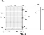
- Figure 5 is a front view of a portion of the galley 104 showing the door 132 in an open position illustrating the seal assembly 140 in a relaxed state between the bottom surface 138 of the door 132 and the floor surface 120.
- the seal 142 transitions from a compressed state (shown in Figure 4 ) to a relaxed state (shown in Figure 5 ) in response to the rotation of the door 132 from the closed position to the open position.
- a height of the seal 142 is greater in the relaxed state than in the compressed state.
- the seal 142 when the seal 142 transitions to the relaxed state, the seal 142 may move vertically with respect to the door 132 and may be positioned at least partially within the housing 144 of the seal assembly 140.
- the vertical translation of the seal 142 with respect to the door 132 from the compressed state to the relaxed state may range from about 0,041 cm (about 0.016 inches) to about 0,635 cm (about 0.25 inches), as non-limiting examples.
- a gap 166 is created between the seal 142 and the floor surface 120.
- Such a gap 166 prevents the seal 142 from dragging along the floor surface 120 as the door 132 is opened and closed, thereby improving the seal between the door 132 and the floor surface 120 as well as increasing the shelf life of the seal 142.
- the system 100 includes one or more hinges 160 coupled to the second side surface 137 of the door 132.
- the system 100 includes two hinges 160 coupled to the first side surface 136 of the door 132.
- the system 100 includes three hinges 160 coupled to the first side surface 136 of the door 132.
- the system 100 includes a plurality of hinges 160 extending an entire length of the second side surface 137. Other numbers of hinges are possible as well.
- the seal 142 described herein may take a variety of forms.
- the seal comprises a brush material.
- the seal 142 may comprise a compressible elastomeric material such as natural rubber, styrene-butadiene rubber (SBR), neoprene, ethylene propylene diene monomer (EPDM), nitrile, butyl, or silicone, as non-limiting examples.
- the durometer of the seal 142 may range from about Shore 00 30 to about Shore A 40, as non-limiting examples.
- the seal 142 may comprise a foam material such as high density Expanded Polypropylene (EPP), Ethylene-Vinyl Acetate (EVA), or Polyethylene-Vinyl Acetate (PEVA), as non-limiting examples.
- the seal 142 may comprise a bulb seal, a foam seal, or any other compressive seal.
- the use of a compressive seal enables the door to use compressive force to conform the seal 142 to the shape of the floor surface 120, thereby providing an improved seal between the bottom surface 138 of the door 132 and the floor surface 120.
- Such an arrangement may be particularly useful in the galley 104 of an aircraft as the floor surface 120 may include non-slip ridges that make sealing of the floor surface 120 more difficult than a flat surface.
- the seal 142 comprises a combination of a compressible elastomeric material and a brush material.
- a brush material seal may provide the benefit of a brush material seal to help seal around the ridges in the floor surface 120 of the galley 104, while also maintaining the benefit of the compressive elastomeric material seal to provide improved sealing between the ridges in the floor surface 120.
- Other arrangements of the seal 142 are possible as well.
- the seal 142 positioned on the bottom surface 138 of the door 132 comprises a first seal.
- the system 100 may further include a second seal 162 positioned on the top surface 139 of the door 132, and a third seal 164 positioned on the second side surface 137 of the door 132.
- the seal 142 comprises the same material as the second seal 162 and the third seal 164.
- the seal 142 comprises a first material, while the second seal 162 and the third seal 164 comprise a second material that is different than the first material.
- the combination of the seal 142, the second seal 162, and the third seal 164 help to seal all sides of the refrigerated chamber 130 of the cart compartment 102 when the door 132 is in the closed position.
- the second seal 162 and the third seal 164 may create a soft close feature of the door 132, thereby preventing the door 132 from slamming shut when in use.
- Figure 6A illustrates a side view of the seal assembly 140 of the system 100 in a relaxed state
- Figure 6B illustrates a side view of the seal assembly 140 of Figure 6A in a compressed state
- the bottom surface 138 of the door 132 includes a cavity 168 between the front wall 124 of the door 132 and the rear wall 126 of the door
- the housing 144 is positioned at least partially in the cavity 168.
- the housing 144 may be at least partially defined by the cavity 168.
- the seal assembly 140 may further include a first edge seal 170 positioned between the housing 144 and the seal 142 adjacent a first side 172 of the housing 144, and a second edge seal 174 positioned between the housing 144 and the seal 142 adjacent a second side 176 of the housing 144 opposite the first side 172 of the housing 144.
- the first edge seal 170 and the second edge seal 174 may help prevent refrigerated air from exiting the refrigerated galley 104 of the aircraft when the door 132 is in the closed position and the seal 142 is in the compressed state.
- the first edge seal 170 and the second edge seal 174 may comprise an elastomeric material configured to stretch when in use.
- the first edge seal 170 may be fixedly coupled to the seal 142 and fixedly coupled to the first side 172 of the housing 144
- the second edge seal 174 may be fixedly coupled to the seal 142 and fixedly coupled to the second side 176 of the housing 144.
- the first edge seal 170 and the second edge seal 174 stretch to seal the edges of the seal 142 and prevent refrigerated air from exiting the refrigerated galley 104.
- the seal 142 translates vertically towards the floor surface 120 in a uniform fashion along the length of the seal 142.
- a portion of the seal 142 closer to the activation mechanism 148 translates vertically before a portion of the seal 142 further away from the activation mechanism 148.
- the seal assembly 140 includes at least one biasing mechanism 146 coupled to the housing 144 and the seal 142 and configured to hold the seal 142 in a relaxed state by applying a biasing force to the seal 142 in a direction away from the floor surface 120 of the galley 104.
- the biasing mechanism 146 may take a variety of forms.
- the biasing mechanism comprises a leaf spring, as shown in Figures 8A-8B and 9A-9B .
- the biasing mechanism 146 comprises a compression spring.
- Other biasing mechanisms are possible as well.
- the biasing mechanism 146 comprises a first biasing mechanism
- the system 100 further comprises a second biasing mechanism (not shown) coupled to the housing 144 and the seal 142.
- the second biasing mechanism may be positioned in parallel with the first biasing mechanism.
- the activation mechanism 148 is configured to overcome the biasing force to transition the seal 142 from the relaxed state to the compressed state in response to a rotation of the door 132 from an open position to a closed position.
- the activation mechanism 148 may take a variety of forms.
- the activation mechanism 148 comprises an actuator pin 178 extending away from the housing 144.
- the activation mechanism 148 further comprises a rod 180 coupled to the actuator pin 178 and extending into the housing 144, and the rod 180 is further coupled to the biasing mechanism 146.
- the actuator pin 178 is depressed as the door 132 transitions from the open position to the closed position.
- the actuator pin 178 As the actuator pin 178 is depressed, the rod 180 moves further into the housing 144, which in turn pushes the biasing mechanism 146 and seal 142 towards the floor surface 120 to transition the seal 142 to the compressed state. As the door 132 transitions back to the open position, the biasing mechanism 146 applies a biasing force to the seal 142 in a direction away from the floor surface 120 to thereby return the seal 142 to the relaxed state.
- the activation mechanism 148 may include an actuator pin 178 extending away from the housing 144, and a rod 180 coupled to the actuator pin 178 and extending into the housing 144. Further, as shown in Figures 9A-9B , the activation mechanism 148 further comprises a first cam component 182 coupled to the rod 180 and positioned within the housing 144, and a second cam component 184 coupled to the seal 142 and positioned within the housing 144. The first cam component 182 is configured to contact the second cam component 184 when the actuator pin 178 is depressed to thereby transition the seal 142 from the relaxed state to the compressed state.
- the first cam component 182 comprises a first wedge having a first angled cam surface
- the second cam component 184 comprises a second wedge having a second angled cam surface.
- Other cam components are possible as well.
- the actuator pin 178 is depressed as the door 132 transitions from the open position to the closed position.
- the rod 180 moves further into the housing 144, which in turn pushes the first cam component 182 into contact with the second cam component 184.
- the biasing mechanism 146 the seal 142 move towards the floor surface 120 to transition the seal 142 to the compressed state.
- the biasing mechanism 146 applies a biasing force to the seal 142 in a direction away from the floor surface 120 to thereby return the seal 142 to the relaxed state.
- the housing 144 of the seal assembly 140 is moveable relative to the door 132.
- the housing 144 be moveable relative to the door 132 through the activation mechanism 148, or the housing 144 may include a second activation mechanism that is configured to move the housing 144 with respect to the door 132.
- the system 100 may include two distinct movements: (i) the housing 144 relative to the door 132, and (ii) the seal 142 relative to the door 132. Such an arrangement may provide increased opportunity for customization of the amount of vertical travel of the seal 142 to ensure a tight seal between the seal assembly 140 and the floor surface 120.
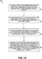
- Figure 10 is a block diagram of an example of a method 200 of assembling an aircraft galley 104 with a seal assembly 140 including a housing 144, a seal 142 coupled to the housing 144, and a biasing mechanism 146 coupled to the housing 144.
- Method 200 shown in Figure 10 presents an embodiment of a method that could be carried out using the system 100 of Figures 1-9B , as an example.
- Method 200 includes one or more operations, functions, or actions as illustrated by one or more of blocks 202-208. Although the blocks are illustrated in a sequential order, these blocks may also be performed in parallel, and/or in a different order than those described herein. Also, the various blocks may be combined into fewer blocks, divided into additional blocks, and/or removed based upon the desired implementation.
- the method 200 includes coupling a door 132 to a door frame 134 above a floor surface 120 of the galley 104 to close a galley cart compartment 102.
- the door 132 is configured to rotate from a closed position to an open position.
- the method 200 includes coupling the housing 144 to a bottom surface 138 of the door 132 such that the seal 142 is configured to contact the floor surface 120 when the door 132 is in the closed position.
- the method 200 includes coupling the biasing mechanism 146 to the door 132 and to the housing 144 to hold the seal 142 in a relaxed state by applying a biasing force to the seal 142 in a direction away from the floor surface 120.
- the method 200 includes coupling an activation mechanism 148 proximate to the door frame 134 to interact with the housing 144 to overcome the biasing force to transition the seal 142 from the relaxed state to a compressed state in response to a rotation of the door 132 from the open position to the closed position.
- a height of the seal 142 i.e. a distance of the seal 142 with respect to the floor surface 120 is greater in the relaxed state than in the compressed state.
- the bottom surface 138 of the door includes a cavity 168 between the front wall 124 of the door 132 and the rear wall 126 of the door, and the housing 144 is positioned at least partially in the cavity 168.
- the blocks may represent operations and/or portions thereof and lines connecting the various blocks do not imply any particular order or dependency of the operations or portions thereof. It will be understood that not all dependencies among the various disclosed operations are necessarily represented.
- Figure 10 and the accompanying disclosure describing the operations of the method(s) set forth herein should not be interpreted as necessarily determining a sequence in which the operations are to be performed. Rather, although one illustrative order is indicated, it is to be understood that the sequence of the operations may be modified when appropriate. Accordingly, certain operations may be performed in a different order or simultaneously. Additionally, those skilled in the art will appreciate that not all operations described need be performed.
- first, second, etc. are used herein merely as labels, and are not intended to impose ordinal, positional, or hierarchical requirements on the items to which these terms refer. Moreover, reference to, e.g., a “second” item does not require or preclude the existence of, e.g., a "first” or lower-numbered item, and/or, e.g., a "third" or higher-numbered item.
- a system, apparatus, device, structure, article, element, component, or hardware "configured to” perform a specified function is indeed capable of performing the specified function without any alteration, rather than merely having potential to perform the specified function after further modification.
- the system, apparatus, structure, article, element, component, or hardware "configured to” perform a specified function is specifically selected, created, implemented, utilized, programmed, and/or designed for the purpose of performing the specified function.
- "configured to” denotes existing characteristics of a system, apparatus, structure, article, element, component, or hardware which enable the system, apparatus, structure, article, element, component, or hardware to perform the specified function without further modification.
- a system, apparatus, structure, article, element, component, or hardware described as being “configured to” perform a particular function may additionally or alternatively be described as being “adapted to” and/or as being “operative to” perform that function.
Landscapes
- Engineering & Computer Science (AREA)
- Aviation & Aerospace Engineering (AREA)
- Thermal Sciences (AREA)
- Combustion & Propulsion (AREA)
- Physics & Mathematics (AREA)
- Mechanical Engineering (AREA)
- Chemical & Material Sciences (AREA)
- General Engineering & Computer Science (AREA)
- Civil Engineering (AREA)
- Structural Engineering (AREA)
- Refrigerator Housings (AREA)
- Specific Sealing Or Ventilating Devices For Doors And Windows (AREA)
- Gasket Seals (AREA)
Abstract
Description
- The present disclosure relates generally to a system for sealing a refrigerated compartment, and more particularly, to a system to lift a seal positioned on a bottom surface of a door when the door is opened to prevent the seal from dragging along the floor surface when the door is opened.
- Aircraft galley cart compartments are often refrigerated to keep the contents therein cold. Traditional galley doors in such refrigerated sections use seals to keep the compartment cold. To maximize the internal volume of the compartment, the doors extend to the floor surface, and the seal is positioned along the bottom surface of the door and contacts the floor surface. Existing seals on traditional galley doors may be more accurately described as close-outs. Such seals are typically "whisker brush" devices that allow air flow thru the whiskers and additionally are not fully sealed against the floor surface due to their inability to flex and conform to the floor surface. Further, such a seal is prone to wear and tear as the door is opened and closed as such actions cause the seal to drag along the floor surface. Eventually the seal is replaced during maintenance as it becomes worn. Prior to replacement, a worn seal may enable cooled air to leak from the enclosed galley cart compartment, causing the airplane environmental control systems to work harder than necessary to maintain the appropriate temperature. As such, a need exists for a seal system for the bottom surface of the galley door that has an extended life and improved thermal sealing characteristics.
- In one aspect, the present disclosure provides a system for sealing a refrigerated galley of an aircraft. The system includes (a) a door having a top surface, a bottom surface opposite the top surface, a first side surface, and a second side surface opposite the first side surface, and (b) a seal assembly positioned at the bottom surface of the door. The seal assembly includes (i) a housing coupled to the bottom surface of the door, (ii) a seal positioned at least partially in the housing, wherein the seal is moveable relative to the housing and the door, (iii) a biasing mechanism coupled to the housing and the seal, wherein the biasing mechanism is configured to hold the seal in a relaxed state by applying a biasing force to the seal in a direction away from a floor surface of the refrigerated galley, and (iv) an activation mechanism coupled to the housing, wherein the activation mechanism is configured to transition the seal from the relaxed state to a compressed state in response to a rotation of the door from an open position to a closed position, wherein a height of the seal is greater in the relaxed state than in the compressed state.
- In another aspect, the present disclosure provides a galley for an aircraft. The galley includes (a) a refrigerated cart compartment, (b) a door frame defining a front wall of the refrigerated cart compartment, (c) a door coupled to the door frame at a hinge, the door having a top surface, a bottom surface opposite the top surface, a first side surface, and a second side surface opposite the first side surface, and (d) a seal assembly positioned at the bottom surface of the door. The seal assembly includes (i) a housing coupled to the bottom surface of the door, (ii) a seal positioned at least partially in the housing, wherein the seal is moveable relative to the housing and the door, (iii) a biasing mechanism coupled to the housing and the seal, wherein the biasing mechanism is configured to hold the seal in a relaxed state by applying a biasing force to the seal in a direction away from a floor surface of the galley, and (iv) an activation mechanism coupled to the housing, wherein the activation mechanism is configured to transition the seal from the relaxed state to a compressed state in response to a rotation of the door from an open position to a closed position, wherein a height of the seal is greater in the relaxed state than in the compressed state.
- In yet another aspect, the present disclosure provides a method of assembling an aircraft galley with a seal assembly including a housing, a seal coupled to the housing, and a biasing mechanism coupled to the housing. The method includes coupling a door to a door frame above a floor surface of the aircraft galley to close a galley cart compartment, wherein the door rotates from a closed position to an open position. The method also includes coupling the housing to a bottom surface of the door such that the seal is configured to contact the floor surface when the door is in the closed position. The method also includes coupling the biasing mechanism to the door and to the housing to hold the seal in a relaxed state by applying a biasing force to the seal in a direction away from the floor surface. The method also includes coupling an activation mechanism proximate to the door frame to interact with the housing to overcome the biasing force to transition the seal from the relaxed state to a compressed state in response to a rotation of the door from the open position to the closed position to thereby seal the aircraft galley, wherein a height of the seal is greater in the relaxed state than in the compressed state.
- The features, functions, and advantages that have been discussed can be achieved independently in various examples or may be combined in yet other examples further details of which can be seen with reference to the following description and figures.
- The novel features believed characteristic of the illustrative examples are set forth in the appended claims. The illustrative examples, however, as well as a preferred mode of use, further objectives and descriptions thereof, will best be understood by reference to the following detailed description of an illustrative examples of the present disclosure when read in conjunction with the accompanying figures.
-
Figure 1 illustrates an exemplary galley system for an aircraft. -
Figure 2 illustrates a side view of the galley in accordance with an exemplary embodiment. -
Figure 3 illustrates a front view of the galley in accordance with an exemplary embodiment. -
Figure 4 illustrates a front view of a portion of the galley showing a door in a closed position illustrating a seal assembly in accordance with an exemplary embodiment in a compressed state. -
Figure 5 illustrates a front view of a portion of the galley showing a door in an open position illustrating a seal assembly in accordance with an exemplary embodiment in a relaxed state. -
Figure 6A illustrates a side view of the seal assembly of the galley system in accordance with an exemplary embodiment in a relaxed state. -
Figure 6B illustrates a side view of the seal assembly of the galley system in accordance with an exemplary embodiment in a compressed state. -
Figure 7A illustrates a front view of the seal assembly of the galley system in accordance with an exemplary embodiment in a relaxed state. -
Figure 7B illustrates a front view of the seal assembly of the galley system in accordance with an exemplary embodiment in a transition state. -
Figure 7C illustrates a front view of the seal assembly of the galley system in accordance with an exemplary embodiment in a compressed state. -
Figure 8A illustrates a cross-sectional view of an example seal assembly of the galley system in accordance with an exemplary embodiment in a relaxed state. -
Figure 8B illustrates a cross-sectional view of the example seal assembly ofFigure 8A in accordance with an exemplary embodiment in a compressed state. -
Figure 9A illustrates a cross-sectional view of another example seal assembly of the galley system in accordance with an exemplary embodiment in a relaxed state. -
Figure 9B illustrates a cross-sectional view of the example seal assembly ofFigure 9A in accordance with an exemplary embodiment in a compressed state. -
Figure 10 is a flowchart of a method for sealing a compartment using the system ofFigures 1-9B . - A seal assembly for a galley is provided for an aircraft that seals against a sealing surface of the galley, which may be against the floor or against another surface, such as part of the door frame of the galley. For example, the seal at the seal edge is configured to seal against the door frame between the floor and the bottom of the door to prevent side leakage. The seal is movable to a relaxed state and held in the relaxed state as the door is opened and closed to prevent damage and wear to the seal. In various embodiments, the seal is movably coupled to the door and moved between the relaxed state and a compressed state in which the seal contacts the sealing surface of the galley. In other various embodiments, the seal is movably coupled to the door frame and moved between the relaxed state and the compressed state, such as by the opening and closing action of the door. A more compliant seal can be used, which provides better, more efficient sealing than conventional blade seals or brush seals because the seal is not subjected to wear and tear during opening and closing of the door. Various embodiments of the seal assembly provide a biasing mechanism to hold the seal in the relaxed state and an activation mechanism to transition the seal to the compressed state when the door is closed. In various embodiments, the activation mechanism automatically closes the seal by closing the door and automatically opens the seal by opening the door. Illustrative, non-exhaustive examples, which may or may not be claimed, of the subject matter according the present disclosure are provided below.
- With reference to the Figures,
Figure 1 is a schematic illustration of anexemplary system 100 for anaircraft 106. Thesystem 100 is used to coolgalley carts 108 held incart compartments 102 of agalley 104. Thegalley 104 defines one ormore cart compartments 102, which are typically arranged below acounter 105 of thegalley 104. Thecart compartments 102 are closed bydoors 132 havingseal assemblies 140 for sealing thecart compartments 102, such as at the floor surface and/or around the door frames. Eachcart compartment 102 may hold any number ofgalley carts 108. Thegalley 104 may be used for the storage and/or preparation of food or beverages. Thegalley 104 is positioned within acabin 110 of theaircraft 106, and the cabin of theaircraft 106 is divided into apassenger area 112 and agalley area 114. Thegalley area 114 has a working area for the galley crew forward of thegalley 104 where thecart compartments 102,counter 105 and cabinets or storage bins may be accessed. - As used herein a "cart compartment" is an insulated volume that is utilized to store one or more galley carts on the
aircraft 106. A "galley cart", as used herein, is a portable device that is used to store food and/or beverages that are transported from a caterer to theaircraft 106 or from thecart compartments 102 to other parts of theaircraft 106 for serving the food and/or beverages. The galley carts may include wheels, however some galley carts may be hand carried boxes in some embodiments. - The
system 100 includes a cooling system having one ormore heat exchangers 116 that provides cooled air for thegalley carts 108 in thecart compartment 102. The cooled air from theheat exchangers 116 flows into and out of thecart compartments 102 through supply or return ducts in the rear wall of thegalley 104. -
Figure 2 is a side view of thegalley 104 in accordance with an exemplary embodiment.Figure 3 is a front view of thegalley 104 in accordance with an exemplary embodiment. Thegalley 104 includeswalls 118 or partitions defining afloor surface 120, a top 122, a front 124, a rear 126 opposite the front 124, andopposite sides 128, 129 (which may also be referred to asfloor surface 120,top wall 122,front wall 124,rear wall 126, andside walls 128, 129). Thecounter 105 extends between thesides floor surface 120 and the top 122. Thefloor surface 120 may be the bottom or bottom wall of thegalley 104, for example. - The
cart compartment 102 is positioned below thecounter 105 and may be at least partially defined by thewalls 118 of thegalley 104. Thecart compartment 102 defines achamber 130 configured to receive thegalley carts 108. In an exemplary embodiment, thedoors 132 are provided at thefront 124 of thegalley 104 and close thecart compartment 102. Thedoors 132 are received indoor frames 134 and, in the illustrated embodiment, are hingedly coupled to thedoor frames 134 at one of thefirst side surface 136 or thesecond side surface 137 of thecorresponding door 132. Thedoors 132 are used to hold thegalley carts 108 in thecart compartment 102. Thedoors 132 are also used to contain the cooled air in thecart compartment 102, and may further provide thermal insulation. Abottom surface 138 of eachdoor 132 faces thefloor surface 120. In an exemplary embodiment, when thegalley carts 108 are positioned in thechamber 130, a space is defined about thegalley cart 108, such as in front of thegalley carts 108, behind thegalley carts 108, above thegalley carts 108, and the like to allow air to flow around thegalley carts 108 in the space. - The
galley 104 includes aseal assembly 140 on eachdoor 132 for sealing thecart compartment 102. In the illustrated embodiment, theseal assembly 140 is provided at thebottom surface 138 of thedoor 132 to seal between thebottom surface 138 of the door and thefloor surface 120. However, theseal assembly 140 may additionally or alternatively be provided at other areas of thedoor 132, such as along thefirst side surface 136, thesecond side surface 137, or atop surface 139 of thedoor 132. Optionally,multiple seal assemblies 140 may be provided to seal against multiple surfaces. In other various embodiments, theseal assembly 140 may be coupled to thedoor frame 134 rather than thedoor 132 to seal between thedoor frame 134 and thedoor 132, such as at the space between thebottom surface 138 of thedoor 132 and thefloor surface 120. -
Figure 4 is a front view of a portion of thegalley 104 showing thedoor 132 in a closed position illustrating theseal assembly 140 in a compressed state between thebottom surface 138 of thedoor 132 and thefloor surface 120. Theseal assembly 140 includes aseal 142 configured to be movably coupled to thedoor 132 and ahousing 144 holding theseal 142. Thehousing 144 may be coupled to thebottom surface 138 of thedoor 132, and theseal 142 is positioned at least partially in thehousing 144. In one example, theseal 142 is removably positioned in thehousing 144. Such an embodiment may provide easy cleaning of theseal 142 and/or replacement of theseal 142 as necessary. Theseal assembly 140 includes at least onebiasing mechanism 146 coupled to thehousing 144 and theseal 142 and configured to hold theseal 142 in a relaxed state by applying a biasing force to theseal 142 in a direction away from thefloor surface 120 of thegalley 104. Theseal assembly 140 includes at least oneactivation mechanism 148 operably engaging thehousing 144 to hold theseal 142 in the compressed state. - The
biasing mechanism 146 is configured to hold theseal 142 in the relaxed state by applying a biasing force to thehousing 144. For example, thebiasing mechanism 146 may open theseal assembly 140 prior to opening thedoor 132 or simultaneously as thedoor 132 is being opened. Theactivation mechanism 148 is configured to overcome the biasing force to transition theseal 142 from the relaxed state to the compressed state in response to a rotation of thedoor 132 from an open position to a closed position, or simultaneously as thedoor 132 is being closed, such as immediately before thedoor 132 is moved to the closed position. For example, as thedoor 132 is being closed, theseal assembly 140 remains open but as thedoor 132 approaches the closed position, theactivation mechanism 148 may be used to move theseal 142 to the compressed state. - In the illustrated embodiment, the
seal assembly 140 is provided at thebottom surface 138 of thedoor 132 and closes off aspace 150 between thebottom surface 138 of thedoor 132 and thefloor surface 120. In an exemplary embodiment, at least a portion of thehousing 144 may extend into thedoor 132 and at least a portion of thehousing 144 may extend below thebottom surface 138 of thedoor 132. - The
seal 142 is provided at the bottom of thehousing 144. Theseal 142 includes aseal interface 152 configured to engage a sealingsurface 154 along thefloor surface 120. In an exemplary embodiment, side edges 156 of theseal 142 are configured to engage sealingsurfaces 158 along thedoor frame 134 that extends between thefloor surface 120 and thebottom surface 138 of thedoor 132 to provide side sealing along the side of theseal 142 and prevent side leakage at thedoor frame 134. In the illustrated embodiment, theseal assembly 140 includes a plurality of biasingmechanisms 146 spaced apart along a width of theseal assembly 140 for biasing against different portions of thehousing 144 andseal 142. In the illustrated embodiment, theactivation mechanism 148 is coupled to thedoor frame 134 at thesecond side surface 137 of thedoor 132. A portion of theactivation mechanism 148 is configured to extend into thedoor 132 to engage thehousing 144 for closing theseal assembly 140 when thedoor 132 is closed. In other various embodiments, theseal assembly 140 may includemultiple activation mechanisms 148 configured to engage different portions of thehousing 144. - In various embodiments, another seal assembly (not shown) may be provided at the sides of the
door 132 for sealing at thedoor frame 134 in the space between thefloor surface 120 and thebottom surface 138 of thedoor 132, such as at the sealing surfaces 158. In various embodiments, the seal assembly may be coupled to the door and movable with thedoor 132. In other embodiments, the seal assembly may be coupled to thedoor frame 134. The seal assembly may seal against theseal 142, thehousing 144 or another element. The seal assembly may be movable between opened and sealed positions to reduce wear. For example, the seal assembly may be automatically moved between the relaxed and compressed states by the opening and closing actions of thedoor 132. -
Figure 5 is a front view of a portion of thegalley 104 showing thedoor 132 in an open position illustrating theseal assembly 140 in a relaxed state between thebottom surface 138 of thedoor 132 and thefloor surface 120. As shown inFigures 4-5 , theseal 142 transitions from a compressed state (shown inFigure 4 ) to a relaxed state (shown inFigure 5 ) in response to the rotation of thedoor 132 from the closed position to the open position. In one example, a height of theseal 142 is greater in the relaxed state than in the compressed state. As shown inFigure 5 , when theseal 142 transitions to the relaxed state, theseal 142 may move vertically with respect to thedoor 132 and may be positioned at least partially within thehousing 144 of theseal assembly 140. The vertical translation of theseal 142 with respect to thedoor 132 from the compressed state to the relaxed state may range from about 0,041 cm (about 0.016 inches) to about 0,635 cm (about 0.25 inches), as non-limiting examples. As further shown inFigure 5 , as the door opens agap 166 is created between theseal 142 and thefloor surface 120. Such agap 166 prevents theseal 142 from dragging along thefloor surface 120 as thedoor 132 is opened and closed, thereby improving the seal between thedoor 132 and thefloor surface 120 as well as increasing the shelf life of theseal 142. - In one example, as illustrated in
Figure 5 , thesystem 100 includes one ormore hinges 160 coupled to thesecond side surface 137 of thedoor 132. In another example, thesystem 100 includes twohinges 160 coupled to thefirst side surface 136 of thedoor 132. In another example, thesystem 100 includes threehinges 160 coupled to thefirst side surface 136 of thedoor 132. In yet another example, thesystem 100 includes a plurality ofhinges 160 extending an entire length of thesecond side surface 137. Other numbers of hinges are possible as well. - The
seal 142 described herein may take a variety of forms. In one example, the seal comprises a brush material. In another example, theseal 142 may comprise a compressible elastomeric material such as natural rubber, styrene-butadiene rubber (SBR), neoprene, ethylene propylene diene monomer (EPDM), nitrile, butyl, or silicone, as non-limiting examples. In such an example, the durometer of theseal 142 may range from aboutShore 00 30 to about Shore A 40, as non-limiting examples. In another example, theseal 142 may comprise a foam material such as high density Expanded Polypropylene (EPP), Ethylene-Vinyl Acetate (EVA), or Polyethylene-Vinyl Acetate (PEVA), as non-limiting examples. Theseal 142 may comprise a bulb seal, a foam seal, or any other compressive seal. The use of a compressive seal enables the door to use compressive force to conform theseal 142 to the shape of thefloor surface 120, thereby providing an improved seal between thebottom surface 138 of thedoor 132 and thefloor surface 120. Such an arrangement may be particularly useful in thegalley 104 of an aircraft as thefloor surface 120 may include non-slip ridges that make sealing of thefloor surface 120 more difficult than a flat surface. In yet another example, theseal 142 comprises a combination of a compressible elastomeric material and a brush material. Such an arrangement may provide the benefit of a brush material seal to help seal around the ridges in thefloor surface 120 of thegalley 104, while also maintaining the benefit of the compressive elastomeric material seal to provide improved sealing between the ridges in thefloor surface 120. Other arrangements of theseal 142 are possible as well. - In one example, the
seal 142 positioned on thebottom surface 138 of thedoor 132 comprises a first seal. In such an example, as shown inFigure 5 , thesystem 100 may further include asecond seal 162 positioned on thetop surface 139 of thedoor 132, and athird seal 164 positioned on thesecond side surface 137 of thedoor 132. In one example, theseal 142 comprises the same material as thesecond seal 162 and thethird seal 164. In another example, theseal 142 comprises a first material, while thesecond seal 162 and thethird seal 164 comprise a second material that is different than the first material. The combination of theseal 142, thesecond seal 162, and thethird seal 164 help to seal all sides of therefrigerated chamber 130 of thecart compartment 102 when thedoor 132 is in the closed position. In addition to assisting in sealing thechamber 130, thesecond seal 162 and thethird seal 164 may create a soft close feature of thedoor 132, thereby preventing thedoor 132 from slamming shut when in use. -
Figure 6A illustrates a side view of theseal assembly 140 of thesystem 100 in a relaxed state, andFigure 6B illustrates a side view of theseal assembly 140 ofFigure 6A in a compressed state. As shown inFigures 6A-6B , thebottom surface 138 of thedoor 132 includes acavity 168 between thefront wall 124 of thedoor 132 and therear wall 126 of the door, and thehousing 144 is positioned at least partially in thecavity 168. In alternative embodiments (not shown), thehousing 144 may be at least partially defined by thecavity 168. As further shown inFigures 6A-6B , theseal assembly 140 may further include afirst edge seal 170 positioned between thehousing 144 and theseal 142 adjacent afirst side 172 of thehousing 144, and asecond edge seal 174 positioned between thehousing 144 and theseal 142 adjacent asecond side 176 of thehousing 144 opposite thefirst side 172 of thehousing 144. Thefirst edge seal 170 and thesecond edge seal 174 may help prevent refrigerated air from exiting therefrigerated galley 104 of the aircraft when thedoor 132 is in the closed position and theseal 142 is in the compressed state. Thefirst edge seal 170 and thesecond edge seal 174 may comprise an elastomeric material configured to stretch when in use. As such, and as shown inFigure 6B , thefirst edge seal 170 may be fixedly coupled to theseal 142 and fixedly coupled to thefirst side 172 of thehousing 144, and thesecond edge seal 174 may be fixedly coupled to theseal 142 and fixedly coupled to thesecond side 176 of thehousing 144. As theseal 142 transitions from the relaxed state to the compressed state and seals against thefloor surface 120, thefirst edge seal 170 and thesecond edge seal 174 stretch to seal the edges of theseal 142 and prevent refrigerated air from exiting therefrigerated galley 104. - In one embodiment, as the
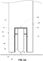
seal 142 transitions from a compressed state to a relaxed state in response to the rotation of thedoor 132 from the closed position to the open position, theseal 142 translates vertically towards thefloor surface 120 in a uniform fashion along the length of theseal 142. In another example, as shown inFigures 7A-7C , as theseal 142 transitions from a compressed state to a relaxed state in response to the rotation of thedoor 132 from the closed position to the open position, a portion of theseal 142 closer to theactivation mechanism 148 translates vertically before a portion of theseal 142 further away from theactivation mechanism 148. Such an arrangement may help ensure a smooth closing of thedoor 132 when in use. - As discussed above, the
seal assembly 140 includes at least onebiasing mechanism 146 coupled to thehousing 144 and theseal 142 and configured to hold theseal 142 in a relaxed state by applying a biasing force to theseal 142 in a direction away from thefloor surface 120 of thegalley 104. Thebiasing mechanism 146 may take a variety of forms. In one example, the biasing mechanism comprises a leaf spring, as shown inFigures 8A-8B and9A-9B . In another example, thebiasing mechanism 146 comprises a compression spring. Other biasing mechanisms are possible as well. In one example, thebiasing mechanism 146 comprises a first biasing mechanism, and thesystem 100 further comprises a second biasing mechanism (not shown) coupled to thehousing 144 and theseal 142. In such an example, the second biasing mechanism may be positioned in parallel with the first biasing mechanism. - As discussed above, the
activation mechanism 148 is configured to overcome the biasing force to transition theseal 142 from the relaxed state to the compressed state in response to a rotation of thedoor 132 from an open position to a closed position. Theactivation mechanism 148 may take a variety of forms. In one example, as shown inFigures 8A-8B , theactivation mechanism 148 comprises anactuator pin 178 extending away from thehousing 144. Further, as shown inFigures 8A-8B , theactivation mechanism 148 further comprises arod 180 coupled to theactuator pin 178 and extending into thehousing 144, and therod 180 is further coupled to thebiasing mechanism 146. In such an example, theactuator pin 178 is depressed as thedoor 132 transitions from the open position to the closed position. As theactuator pin 178 is depressed, therod 180 moves further into thehousing 144, which in turn pushes thebiasing mechanism 146 and seal 142 towards thefloor surface 120 to transition theseal 142 to the compressed state. As thedoor 132 transitions back to the open position, thebiasing mechanism 146 applies a biasing force to theseal 142 in a direction away from thefloor surface 120 to thereby return theseal 142 to the relaxed state. - Another
example activation mechanism 148 is illustrated inFigures 9A-9B . As shown inFigures 9A-9B , theactivation mechanism 148 may include anactuator pin 178 extending away from thehousing 144, and arod 180 coupled to theactuator pin 178 and extending into thehousing 144. Further, as shown inFigures 9A-9B , theactivation mechanism 148 further comprises afirst cam component 182 coupled to therod 180 and positioned within thehousing 144, and asecond cam component 184 coupled to theseal 142 and positioned within thehousing 144. Thefirst cam component 182 is configured to contact thesecond cam component 184 when theactuator pin 178 is depressed to thereby transition theseal 142 from the relaxed state to the compressed state. In one particular example, as illustrated inFigures 9A-9B , thefirst cam component 182 comprises a first wedge having a first angled cam surface, and thesecond cam component 184 comprises a second wedge having a second angled cam surface. Other cam components are possible as well. - In such an example, the
actuator pin 178 is depressed as thedoor 132 transitions from the open position to the closed position. As theactuator pin 178 is depressed, therod 180 moves further into thehousing 144, which in turn pushes thefirst cam component 182 into contact with thesecond cam component 184. As thefirst cam component 182 contacts thesecond cam component 184, thebiasing mechanism 146 theseal 142 move towards thefloor surface 120 to transition theseal 142 to the compressed state. As thedoor 132 transitions back to the open position, thebiasing mechanism 146 applies a biasing force to theseal 142 in a direction away from thefloor surface 120 to thereby return theseal 142 to the relaxed state. - In one example, the
housing 144 of theseal assembly 140 is moveable relative to thedoor 132. In such an example, thehousing 144 be moveable relative to thedoor 132 through theactivation mechanism 148, or thehousing 144 may include a second activation mechanism that is configured to move thehousing 144 with respect to thedoor 132. As such, thesystem 100 may include two distinct movements: (i) thehousing 144 relative to thedoor 132, and (ii) theseal 142 relative to thedoor 132. Such an arrangement may provide increased opportunity for customization of the amount of vertical travel of theseal 142 to ensure a tight seal between theseal assembly 140 and thefloor surface 120. -
Figure 10 is a block diagram of an example of amethod 200 of assembling anaircraft galley 104 with aseal assembly 140 including ahousing 144, aseal 142 coupled to thehousing 144, and abiasing mechanism 146 coupled to thehousing 144.Method 200 shown inFigure 10 presents an embodiment of a method that could be carried out using thesystem 100 ofFigures 1-9B , as an example.Method 200 includes one or more operations, functions, or actions as illustrated by one or more of blocks 202-208. Although the blocks are illustrated in a sequential order, these blocks may also be performed in parallel, and/or in a different order than those described herein. Also, the various blocks may be combined into fewer blocks, divided into additional blocks, and/or removed based upon the desired implementation. - Initially, at
block 202, themethod 200 includes coupling adoor 132 to adoor frame 134 above afloor surface 120 of thegalley 104 to close agalley cart compartment 102. Thedoor 132 is configured to rotate from a closed position to an open position. Atblock 204, themethod 200 includes coupling thehousing 144 to abottom surface 138 of thedoor 132 such that theseal 142 is configured to contact thefloor surface 120 when thedoor 132 is in the closed position. Atblock 206, themethod 200 includes coupling thebiasing mechanism 146 to thedoor 132 and to thehousing 144 to hold theseal 142 in a relaxed state by applying a biasing force to theseal 142 in a direction away from thefloor surface 120. At block 208, themethod 200 includes coupling anactivation mechanism 148 proximate to thedoor frame 134 to interact with thehousing 144 to overcome the biasing force to transition theseal 142 from the relaxed state to a compressed state in response to a rotation of thedoor 132 from the open position to the closed position. As discussed above, a height of the seal 142 (i.e. a distance of theseal 142 with respect to the floor surface 120) is greater in the relaxed state than in the compressed state. - In one example, as discussed above, the
bottom surface 138 of the door includes acavity 168 between thefront wall 124 of thedoor 132 and therear wall 126 of the door, and thehousing 144 is positioned at least partially in thecavity 168.
In the above description, numerous specific details are set forth to provide a thorough understanding of the disclosed concepts, which may be practiced without some or all of these particulars. In other instances, details of known devices and/or processes have been omitted to avoid unnecessarily obscuring the disclosure. While some concepts were described in conjunction with specific examples, it will be understood that these examples are not intended to be limiting. - In
Figure 10 , referred to above, the blocks may represent operations and/or portions thereof and lines connecting the various blocks do not imply any particular order or dependency of the operations or portions thereof. It will be understood that not all dependencies among the various disclosed operations are necessarily represented.Figure 10 and the accompanying disclosure describing the operations of the method(s) set forth herein should not be interpreted as necessarily determining a sequence in which the operations are to be performed. Rather, although one illustrative order is indicated, it is to be understood that the sequence of the operations may be modified when appropriate. Accordingly, certain operations may be performed in a different order or simultaneously. Additionally, those skilled in the art will appreciate that not all operations described need be performed. - Unless otherwise indicated, the terms "first," "second," etc. are used herein merely as labels, and are not intended to impose ordinal, positional, or hierarchical requirements on the items to which these terms refer. Moreover, reference to, e.g., a "second" item does not require or preclude the existence of, e.g., a "first" or lower-numbered item, and/or, e.g., a "third" or higher-numbered item.
- Reference herein to "one example" or "one embodiment" means that one or more feature, structure, or characteristic described in connection with the example is included in at least one implementation. The phrase "one example" or "one embodiment" in various places in the specification may or may not be referring to the same example or embodiment.
- As used herein, a system, apparatus, device, structure, article, element, component, or hardware "configured to" perform a specified function is indeed capable of performing the specified function without any alteration, rather than merely having potential to perform the specified function after further modification. In other words, the system, apparatus, structure, article, element, component, or hardware "configured to" perform a specified function is specifically selected, created, implemented, utilized, programmed, and/or designed for the purpose of performing the specified function. As used herein, "configured to" denotes existing characteristics of a system, apparatus, structure, article, element, component, or hardware which enable the system, apparatus, structure, article, element, component, or hardware to perform the specified function without further modification. For purposes of this disclosure, a system, apparatus, structure, article, element, component, or hardware described as being "configured to" perform a particular function may additionally or alternatively be described as being "adapted to" and/or as being "operative to" perform that function.
- As used herein, with respect to measurements, "about" and "substantially" each means +/-5%.
- Further, the disclosure comprises embodiments according to the following clauses:
- Clause 1. A system (100) for sealing a refrigerated galley (104) of an aircraft (106), the system (100) comprising:
- a door (132) having a top surface (139), a bottom surface (138) opposite the top surface (139), a first side surface (136), and a second side surface (137) opposite the first side surface (136); and
- a seal assembly (140) positioned at the bottom surface (138) of the door (132), the seal assembly (140) comprising:
- a housing (144) coupled to the bottom surface (138) of the door (132);
- a seal (140) positioned at least partially in the housing (144), wherein the seal (142) is moveable relative to the housing (144) and the door (132);
- a biasing mechanism (146) coupled to the housing (144) and the seal (142), wherein the biasing mechanism (146) is configured to hold the seal (142) in a relaxed state by applying a biasing force to the seal (142) in a direction away from a floor surface (120) of the refrigerated galley (104); and
- an activation mechanism (148) coupled to the housing (144), wherein the activation mechanism (148) is configured to transition the seal (142) from the relaxed state to a compressed state in response to a rotation of the door (132) from an open position to a closed position, wherein a height of the seal (142) is greater in the relaxed state than in the compressed state.
- Clause 2. The system (100) of Clause 1, wherein the biasing mechanism (146) comprises a leaf spring.
- Clause 3. The system (100) of Clause 1 or 2, wherein the biasing mechanism (146) comprises a first biasing mechanism, the system (100) further comprising:
a second biasing mechanism coupled to the housing (144) and the seal (142), wherein the second biasing mechanism is positioned in parallel with the first biasing mechanism. - Clause 4. The system (100) of any one of Clauses 1-3, further comprising:
- a second seal (162) positioned on the top surface (139) of the door (132); and
- a third seal (164) positioned on the first side surface (136) of the door (132).
- Clause 5. The system (100) of any one of Clauses 1-4, further comprising:
- a first edge seal (170) positioned between the housing (144) and the seal (140) adjacent a first side (172) of the housing (144); and
- a second edge seal (174) positioned between the housing (144) and the seal (140) adjacent a second side (176) of the housing (144) opposite the first side (172) of the housing (144), wherein the first edge seal (170) and the second edge seal (174) prevent refrigerated air from exiting the refrigerated galley (104) of the aircraft (106) when the door (132) is in the closed position.
- Clause 6. The system (100) of any one of Clauses 1-5, wherein the bottom surface (138) of the door (132) includes a cavity (168) between a front wall (124) and a rear wall (126) of the door (132), and wherein at least one of:
- the housing (144) is positioned at least partially in the cavity (168); or
- the housing (144) is at least partially defined by the cavity (168).
- Clause 7. The system (100) of any one of Clauses 1-6, wherein the activation mechanism (148) comprises:
- an actuator pin (178) extending away from the housing (144); and
- a rod (180) coupled to the actuator pin (178) and extending into the housing (144), wherein the rod (180) is further coupled to the biasing mechanism (146).
- Clause 8. The system (100) of any one of Clauses 1-7, wherein the activation mechanism (148) comprises:
- an actuator pin (178) extending away from the housing (144);
- a rod (180) coupled to the actuator pin (178) and extending into the housing (144);
- a first cam component (182) coupled to the rod (178) and positioned within the housing (144) ; and
- a second cam component (184) coupled to the seal (140) and positioned within the housing (144), wherein the first cam component (182) is configured to contact the second cam component (184) when the actuator pin (178) is depressed to thereby transition the seal (140) from the relaxed state to the compressed state.
- Clause 9. The system (100) of Clause 8, wherein the first cam component (182) comprises a first wedge having a first angled cam surface, and wherein the second cam component (184) comprises a second wedge having a second angled cam surface.
- Clause 10. The system (100) of any one of Clauses 1-9, wherein the seal (140) comprises an elastomeric material, a brush material, or a combination thereof.
- Clause 11. The system (100) of any one of Clauses 1-10, wherein the housing (144) is moveable relative to the door (132).
- Clause 12. The system (100) of any one of Clauses 1-11, wherein the seal (140) is removably positioned in the housing (144).
- Clause 13. A galley (104) for an aircraft (106) comprising:
- a refrigerated cart compartment (102);
- a door frame (134) defining a front wall (124) of the refrigerated cart compartment (102);
- a door (132) coupled to the door frame (134) at a hinge (160), the door (132) having a top surface (139), a bottom surface (138) opposite the top surface (139), a first side surface (136), and a second side surface (137) opposite the first side surface (136); and
- a seal assembly (140) positioned at the bottom surface (138) of the door (132), the seal assembly (140) comprising:
- a housing (144) coupled to the bottom surface (138) of the door (132);
- a seal (140) positioned at least partially in the housing (144), wherein the seal (142) is moveable relative to the housing (144) and the door (132);
- a biasing mechanism (146) coupled to the housing (144) and the seal (142), wherein the biasing mechanism (146) is configured to hold the seal (142) in a relaxed state by applying a biasing force to the seal (142) in a direction away from a floor surface (120) of the galley (104); and
- an activation mechanism (148) coupled to the housing (144), wherein the activation mechanism (148) is configured to transition the seal (142) from the relaxed state to a compressed state in response to a rotation of the door (132) from an open position to a closed position, wherein a height of the seal (142) is greater in the relaxed state than in the compressed state.
- Clause 14. The galley (104) of Clause 13, further comprising:
- a first edge seal (170) positioned between the housing (144) and the seal (140) adjacent a first side (172) of the housing (144); and
- a second edge seal (174) positioned between the housing (144) and the seal (140) adjacent a second side (176) of the housing (144) opposite the first side (172) of the housing (144), wherein the first edge seal (170) and the second edge seal (174) prevent refrigerated air from exiting the galley (104) of the aircraft (106) when the door (132) is in the closed position.
- Clause 15. The galley (104) of Clause 13 or 14, wherein the activation mechanism (148) comprises:
- an actuator pin (178) extending away from the housing (144); and
- a rod (180) coupled to the actuator pin (178) and extending into the housing (144), wherein the rod (180) is further coupled to the biasing mechanism (146).
- Clause 16. The galley (104) of Clause 13 or 14, wherein the activation mechanism (148) comprises:
- an actuator pin (178) extending away from the housing (144);
- a rod (180) coupled to the actuator pin (178) and extending into the housing (144);
- a first cam component (182) coupled to the rod (178) and positioned within the housing (144) ; and
- a second cam component (184) coupled to the seal (140) and positioned within the housing (144), wherein the first cam component (182) is configured to contact the second cam component (184) when the actuator pin (178) is depressed to thereby transition the seal (140) from the relaxed state to the compressed state.
- Clause 17. The galley (104) of Clause 16, wherein the first cam component (182) comprises a first wedge having a first angled cam surface, and wherein the second cam component (184) comprises a second wedge having a second angled cam surface.
- Clause 18. The galley (104) of any one of Clauses 13-17, wherein the housing (144) is moveable relative to the door (132).
- Clause 19. A method (200) of assembling an aircraft galley (104) with a seal assembly (140) including a housing (144), a seal (142) coupled to the housing (144), and a biasing mechanism (146) coupled to the housing (144), the method (200) comprising:
- coupling (204) a door (132) to a door frame (134) above a floor surface (120) of the aircraft galley (104) to close a galley cart compartment (102), wherein the door (132) rotates from a closed position to an open position;
- coupling (206) the housing (144) to a bottom surface (138) of the door (132) such that the seal (142) is configured to contact the floor surface (120) when the door (132) is in the closed position;
- coupling (208) the biasing mechanism (146) to the door (132) and to the housing (144) to hold the seal (142) in a relaxed state by applying a biasing force to the seal (142) in a direction away from the floor surface (120); and
- coupling (210) an activation mechanism (148) proximate to the door frame (134) to interact with the housing (144) to overcome the biasing force to transition the seal (142) from the relaxed state to a compressed state in response to a rotation of the door (132) from the open position to the closed position to thereby seal the aircraft galley (104), wherein a height of the seal (142) is greater in the relaxed state than in the compressed state.
- Clause 20. The method (200) of Clause 19, wherein the bottom surface (138) of the door (132) includes a cavity (168) between a front wall (124) and a rear wall (126) of the door (132), and wherein the housing (144) is positioned at least partially in the cavity (168).
Claims (15)
- A system (100) for sealing a refrigerated galley (104) of an aircraft (106), the system (100) comprising:a door (132) having a top surface (139), a bottom surface (138) opposite the top surface (139), a first side surface (136), and a second side surface (137) opposite the first side surface (136); anda seal assembly (140) positioned at the bottom surface (138) of the door (132), the seal assembly (140) comprising:a housing (144) coupled to the bottom surface (138) of the door (132);a seal (140) positioned at least partially in the housing (144), wherein the seal (142) is moveable relative to the housing (144) and the door (132);a biasing mechanism (146) coupled to the housing (144) and the seal (142), wherein the biasing mechanism (146) is configured to hold the seal (142) in a relaxed state by applying a biasing force to the seal (142) in a direction away from a floor surface (120) of the refrigerated galley (104); andan activation mechanism (148) coupled to the housing (144), wherein the activation mechanism (148) is configured to transition the seal (142) from the relaxed state to a compressed state in response to a rotation of the door (132) from an open position to a closed position, wherein a height of the seal (142) is greater in the relaxed state than in the compressed state.
- The system (100) of claim 1, wherein the biasing mechanism (146) comprises a leaf spring.
- The system (100) of claim 1 or 2, wherein the biasing mechanism (146) comprises a first biasing mechanism, the system (100) further comprising:
a second biasing mechanism coupled to the housing (144) and the seal (142), wherein the second biasing mechanism is positioned in parallel with the first biasing mechanism. - The system (100) of any one of claims 1-3, further comprising:a second seal (162) positioned on the top surface (139) of the door (132); anda third seal (164) positioned on the first side surface (136) of the door (132).
- The system (100) of any one of claims 1-4, further comprising:a first edge seal (170) positioned between the housing (144) and the seal (140) adjacent a first side (172) of the housing (144); anda second edge seal (174) positioned between the housing (144) and the seal (140) adjacent a second side (176) of the housing (144) opposite the first side (172) of the housing (144), wherein the first edge seal (170) and the second edge seal (174) prevent refrigerated air from exiting the refrigerated galley (104) of the aircraft (106) when the door (132) is in the closed position.
- The system (100) of any one of claims 1-5, wherein the bottom surface (138) of the door (132) includes a cavity (168) between a front wall (124) and a rear wall (126) of the door (132), and wherein at least one of:the housing (144) is positioned at least partially in the cavity (168); orthe housing (144) is at least partially defined by the cavity (168).
- The system (100) of any one of claims 1-6, wherein the activation mechanism (148) comprises:an actuator pin (178) extending away from the housing (144); anda rod (180) coupled to the actuator pin (178) and extending into the housing (144), wherein the rod (180) is further coupled to the biasing mechanism (146).
- The system (100) of any one of claims 1-6, wherein the activation mechanism (148) comprises:an actuator pin (178) extending away from the housing (144);a rod (180) coupled to the actuator pin (178) and extending into the housing (144);a first cam component (182) coupled to the rod (178) and positioned within the housing (144) ; anda second cam component (184) coupled to the seal (140) and positioned within the housing (144), wherein the first cam component (182) is configured to contact the second cam component (184) when the actuator pin (178) is depressed to thereby transition the seal (140) from the relaxed state to the compressed state.
- The system (100) of claim 7 or 8, wherein the first cam component (182) comprises a first wedge having a first angled cam surface, and wherein the second cam component (184) comprises a second wedge having a second angled cam surface.
- The system (100) of any one of claims 1-9, wherein the seal (140) comprises an elastomeric material, a brush material, or a combination thereof.
- The system (100) of any one of claims 1-10, wherein the housing (144) is moveable relative to the door (132).
- The system (100) of any one of claims 1-11, wherein the seal (140) is removably positioned in the housing (144).
- A method (200) of assembling an aircraft galley (104) with a seal assembly (140) including a housing (144), a seal (142) coupled to the housing (144), and a biasing mechanism (146) coupled to the housing (144), the method (200) comprising:coupling (204) a door (132) to a door frame (134) above a floor surface (120) of the aircraft galley (104) to close a galley cart compartment (102), wherein the door (132) rotates from a closed position to an open position;coupling (206) the housing (144) to a bottom surface (138) of the door (132) such that the seal (142) is configured to contact the floor surface (120) when the door (132) is in the closed position;coupling (208) the biasing mechanism (146) to the door (132) and to the housing (144) to hold the seal (142) in a relaxed state by applying a biasing force to the seal (142) in a direction away from the floor surface (120); andcoupling (210) an activation mechanism (148) proximate to the door frame (134) to interact with the housing (144) to overcome the biasing force to transition the seal (142) from the relaxed state to a compressed state in response to a rotation of the door (132) from the open position to the closed position to thereby seal the aircraft galley (104), wherein a height of the seal (142) is greater in the relaxed state than in the compressed state.
- The method (200) of claim 13, wherein the bottom surface (138) of the door (132) includes a cavity (168) between a front wall (124) and a rear wall (126) of the door (132), and wherein the housing (144) is positioned at least partially in the cavity (168).
- The method of claim 13 or 14, wherein the housing (144) is moveable relative to the door (132).
Applications Claiming Priority (1)
| Application Number | Priority Date | Filing Date | Title |
|---|---|---|---|
| US16/451,080 US11525622B2 (en) | 2019-06-25 | 2019-06-25 | Systems and methods for sealing a refrigerated galley of an aircraft |
Publications (2)
| Publication Number | Publication Date |
|---|---|
| EP3757007A1 true EP3757007A1 (en) | 2020-12-30 |
| EP3757007B1 EP3757007B1 (en) | 2023-08-02 |
Family
ID=70740470
Family Applications (1)
| Application Number | Title | Priority Date | Filing Date |
|---|---|---|---|
| EP20175135.1A Active EP3757007B1 (en) | 2019-06-25 | 2020-05-18 | Systems and methods for sealing a refrigerated galley of an aircraft |
Country Status (4)
| Country | Link |
|---|---|
| US (1) | US11525622B2 (en) |
| EP (1) | EP3757007B1 (en) |
| CN (1) | CN112124598A (en) |
| CA (1) | CA3081301A1 (en) |
Families Citing this family (2)
| Publication number | Priority date | Publication date | Assignee | Title |
|---|---|---|---|---|
| USD1002488S1 (en) * | 2021-02-19 | 2023-10-24 | Rh Us, Llc | Aircraft galley |
| USD1001703S1 (en) * | 2021-02-19 | 2023-10-17 | Rh Us, Llc | Aircraft lavatory |
Citations (7)
| Publication number | Priority date | Publication date | Assignee | Title |
|---|---|---|---|---|
| US3871133A (en) * | 1974-01-14 | 1975-03-18 | Jr Chester W Ellingson | Door bottom weather sealing structure |
| US4406088A (en) * | 1981-11-09 | 1983-09-27 | Berndt Jr Fred P | Door bottom sealing apparatus |
| EP1347146A2 (en) * | 2002-03-20 | 2003-09-24 | Luigi Geron | Draft stopper device, particularly for hinged or sliding doors and similar door frames, as well as manufacturing method |
| DE202007016379U1 (en) * | 2007-11-21 | 2009-04-09 | F. Athmer Ohg | Lowerable bottom seal with at least partially soft trigger element |
| US20130219792A1 (en) * | 2010-09-07 | 2013-08-29 | Rbp Associates Limited | "automatic door bottom drop-down seal" |
| EP2770152A1 (en) * | 2013-02-20 | 2014-08-27 | C.C.E. Costruzioni Chiusure Ermetiche S.r.l. | Seal and sealing device for door and window leaves |
| US20190002105A1 (en) * | 2017-06-29 | 2019-01-03 | The Boeing Company | Seal assembly for a galley door of a galley and method of assembling a galley with a seal assembly |
Family Cites Families (3)
| Publication number | Priority date | Publication date | Assignee | Title |
|---|---|---|---|---|
| KR101462480B1 (en) * | 2012-11-28 | 2014-11-18 | 안계원 | The door clearance closing device |
| KR101588239B1 (en) * | 2013-11-11 | 2016-01-25 | 지엘테크(주) | A door intercepting unit |
| CN205259893U (en) * | 2015-12-15 | 2016-05-25 | 广东坚美铝型材厂(集团)有限公司 | Vertical hinged door adhesive tape of stretching out and drawing back and seal structure thereof |
-
2019
- 2019-06-25 US US16/451,080 patent/US11525622B2/en active Active
-
2020
- 2020-05-15 CA CA3081301A patent/CA3081301A1/en active Pending
- 2020-05-18 EP EP20175135.1A patent/EP3757007B1/en active Active
- 2020-06-19 CN CN202010562716.6A patent/CN112124598A/en active Pending
Patent Citations (7)
| Publication number | Priority date | Publication date | Assignee | Title |
|---|---|---|---|---|
| US3871133A (en) * | 1974-01-14 | 1975-03-18 | Jr Chester W Ellingson | Door bottom weather sealing structure |
| US4406088A (en) * | 1981-11-09 | 1983-09-27 | Berndt Jr Fred P | Door bottom sealing apparatus |
| EP1347146A2 (en) * | 2002-03-20 | 2003-09-24 | Luigi Geron | Draft stopper device, particularly for hinged or sliding doors and similar door frames, as well as manufacturing method |
| DE202007016379U1 (en) * | 2007-11-21 | 2009-04-09 | F. Athmer Ohg | Lowerable bottom seal with at least partially soft trigger element |
| US20130219792A1 (en) * | 2010-09-07 | 2013-08-29 | Rbp Associates Limited | "automatic door bottom drop-down seal" |
| EP2770152A1 (en) * | 2013-02-20 | 2014-08-27 | C.C.E. Costruzioni Chiusure Ermetiche S.r.l. | Seal and sealing device for door and window leaves |
| US20190002105A1 (en) * | 2017-06-29 | 2019-01-03 | The Boeing Company | Seal assembly for a galley door of a galley and method of assembling a galley with a seal assembly |
Also Published As
| Publication number | Publication date |
|---|---|
| US20200408461A1 (en) | 2020-12-31 |
| EP3757007B1 (en) | 2023-08-02 |
| US11525622B2 (en) | 2022-12-13 |
| CN112124598A (en) | 2020-12-25 |
| CA3081301A1 (en) | 2020-12-25 |
Similar Documents
| Publication | Publication Date | Title |
|---|---|---|
| US10865599B2 (en) | Seal assembly for a galley door of a galley and method of assembling a galley with a seal assembly | |
| US10054360B2 (en) | Refrigerator | |
| US20130049562A1 (en) | Refrigerator | |
| EP3757007B1 (en) | Systems and methods for sealing a refrigerated galley of an aircraft | |
| EP1566602B1 (en) | Refrigerator | |
| RU2627067C1 (en) | Fridge door and fridge including such fridge door | |
| KR20110064720A (en) | Refrigerator | |
| KR100951287B1 (en) | Refrigerator with compartment | |
| CN115321038B (en) | Container door assembly and refrigerated container having the same | |
| CN204547888U (en) | A kind of Novel cold chain logistic car | |
| CN106322901A (en) | Side-by-side refrigerator and vertical beam guiding device thereof | |
| US7543897B2 (en) | Door opening prevention device for refrigerator | |
| KR101659957B1 (en) | Refrigerator having sliding door | |
| CN205523898U (en) | Three temperature carriages and use haulage vehicle in this carriage | |
| JP2003302150A (en) | refrigerator | |
| CN115027578B (en) | Environment-friendly energy-saving cold chain carriage for food transportation | |
| CN212409159U (en) | A kind of refrigerator | |
| JP2006335081A (en) | Partitioning structure for transport boxes | |
| CN111566424A (en) | Method and apparatus for a French double door for sealing a freezer compartment | |
| CN211823449U (en) | refrigerator | |
| JP2001151007A (en) | Structure for freezer/refrigerator of van type truck | |
| JP2006258307A (en) | Storage | |
| CN222202229U (en) | Rear door plate of refrigerating compartment and refrigerating compartment | |
| CN119146676B (en) | Constant temperature and humidity control cabinet | |
| KR102206240B1 (en) | Refrigerator |
Legal Events
| Date | Code | Title | Description |
|---|---|---|---|
| PUAI | Public reference made under article 153(3) epc to a published international application that has entered the european phase |
Free format text: ORIGINAL CODE: 0009012 |
|
| STAA | Information on the status of an ep patent application or granted ep patent |
Free format text: STATUS: THE APPLICATION HAS BEEN PUBLISHED |
|
| AK | Designated contracting states |
Kind code of ref document: A1 Designated state(s): AL AT BE BG CH CY CZ DE DK EE ES FI FR GB GR HR HU IE IS IT LI LT LU LV MC MK MT NL NO PL PT RO RS SE SI SK SM TR |
|
| AX | Request for extension of the european patent |
Extension state: BA ME |
|
| STAA | Information on the status of an ep patent application or granted ep patent |
Free format text: STATUS: REQUEST FOR EXAMINATION WAS MADE |
|
| 17P | Request for examination filed |
Effective date: 20210621 |
|
| RBV | Designated contracting states (corrected) |
Designated state(s): AL AT BE BG CH CY CZ DE DK EE ES FI FR GB GR HR HU IE IS IT LI LT LU LV MC MK MT NL NO PL PT RO RS SE SI SK SM TR |
|
| STAA | Information on the status of an ep patent application or granted ep patent |
Free format text: STATUS: EXAMINATION IS IN PROGRESS |
|
| 17Q | First examination report despatched |
Effective date: 20220127 |
|
| RAP3 | Party data changed (applicant data changed or rights of an application transferred) |
Owner name: THE BOEING COMPANY |
|
| GRAP | Despatch of communication of intention to grant a patent |
Free format text: ORIGINAL CODE: EPIDOSNIGR1 |
|
| RIC1 | Information provided on ipc code assigned before grant |
Ipc: E06B 7/20 20060101ALN20230301BHEP Ipc: E06B 7/21 20060101ALI20230301BHEP Ipc: E06B 7/215 20060101ALI20230301BHEP Ipc: B64D 11/04 20060101AFI20230301BHEP |
|
| STAA | Information on the status of an ep patent application or granted ep patent |
Free format text: STATUS: GRANT OF PATENT IS INTENDED |
|
| INTG | Intention to grant announced |
Effective date: 20230406 |
|
| GRAS | Grant fee paid |
Free format text: ORIGINAL CODE: EPIDOSNIGR3 |
|
| GRAA | (expected) grant |
Free format text: ORIGINAL CODE: 0009210 |
|
| STAA | Information on the status of an ep patent application or granted ep patent |
Free format text: STATUS: THE PATENT HAS BEEN GRANTED |
|
| AK | Designated contracting states |
Kind code of ref document: B1 Designated state(s): AL AT BE BG CH CY CZ DE DK EE ES FI FR GB GR HR HU IE IS IT LI LT LU LV MC MK MT NL NO PL PT RO RS SE SI SK SM TR |
|
| REG | Reference to a national code |
Ref country code: GB Ref legal event code: FG4D |
|
| REG | Reference to a national code |
Ref country code: CH Ref legal event code: EP |
|
| REG | Reference to a national code |
Ref country code: DE Ref legal event code: R096 Ref document number: 602020014743 Country of ref document: DE |
|
| REG | Reference to a national code |
Ref country code: IE Ref legal event code: FG4D |
|
| P01 | Opt-out of the competence of the unified patent court (upc) registered |
Effective date: 20230731 |
|
| REG | Reference to a national code |
Ref country code: LT Ref legal event code: MG9D |
|
| REG | Reference to a national code |
Ref country code: NL Ref legal event code: MP Effective date: 20230802 |
|
| REG | Reference to a national code |
Ref country code: AT Ref legal event code: MK05 Ref document number: 1594470 Country of ref document: AT Kind code of ref document: T Effective date: 20230802 |
|
| PG25 | Lapsed in a contracting state [announced via postgrant information from national office to epo] |
Ref country code: GR Free format text: LAPSE BECAUSE OF FAILURE TO SUBMIT A TRANSLATION OF THE DESCRIPTION OR TO PAY THE FEE WITHIN THE PRESCRIBED TIME-LIMIT Effective date: 20231103 |
|
| PG25 | Lapsed in a contracting state [announced via postgrant information from national office to epo] |
Ref country code: IS Free format text: LAPSE BECAUSE OF FAILURE TO SUBMIT A TRANSLATION OF THE DESCRIPTION OR TO PAY THE FEE WITHIN THE PRESCRIBED TIME-LIMIT Effective date: 20231202 |
|
| PG25 | Lapsed in a contracting state [announced via postgrant information from national office to epo] |
Ref country code: SE Free format text: LAPSE BECAUSE OF FAILURE TO SUBMIT A TRANSLATION OF THE DESCRIPTION OR TO PAY THE FEE WITHIN THE PRESCRIBED TIME-LIMIT Effective date: 20230802 Ref country code: RS Free format text: LAPSE BECAUSE OF FAILURE TO SUBMIT A TRANSLATION OF THE DESCRIPTION OR TO PAY THE FEE WITHIN THE PRESCRIBED TIME-LIMIT Effective date: 20230802 Ref country code: PT Free format text: LAPSE BECAUSE OF FAILURE TO SUBMIT A TRANSLATION OF THE DESCRIPTION OR TO PAY THE FEE WITHIN THE PRESCRIBED TIME-LIMIT Effective date: 20231204 Ref country code: NO Free format text: LAPSE BECAUSE OF FAILURE TO SUBMIT A TRANSLATION OF THE DESCRIPTION OR TO PAY THE FEE WITHIN THE PRESCRIBED TIME-LIMIT Effective date: 20231102 Ref country code: NL Free format text: LAPSE BECAUSE OF FAILURE TO SUBMIT A TRANSLATION OF THE DESCRIPTION OR TO PAY THE FEE WITHIN THE PRESCRIBED TIME-LIMIT Effective date: 20230802 Ref country code: LV Free format text: LAPSE BECAUSE OF FAILURE TO SUBMIT A TRANSLATION OF THE DESCRIPTION OR TO PAY THE FEE WITHIN THE PRESCRIBED TIME-LIMIT Effective date: 20230802 Ref country code: LT Free format text: LAPSE BECAUSE OF FAILURE TO SUBMIT A TRANSLATION OF THE DESCRIPTION OR TO PAY THE FEE WITHIN THE PRESCRIBED TIME-LIMIT Effective date: 20230802 Ref country code: IS Free format text: LAPSE BECAUSE OF FAILURE TO SUBMIT A TRANSLATION OF THE DESCRIPTION OR TO PAY THE FEE WITHIN THE PRESCRIBED TIME-LIMIT Effective date: 20231202 Ref country code: HR Free format text: LAPSE BECAUSE OF FAILURE TO SUBMIT A TRANSLATION OF THE DESCRIPTION OR TO PAY THE FEE WITHIN THE PRESCRIBED TIME-LIMIT Effective date: 20230802 Ref country code: GR Free format text: LAPSE BECAUSE OF FAILURE TO SUBMIT A TRANSLATION OF THE DESCRIPTION OR TO PAY THE FEE WITHIN THE PRESCRIBED TIME-LIMIT Effective date: 20231103 Ref country code: FI Free format text: LAPSE BECAUSE OF FAILURE TO SUBMIT A TRANSLATION OF THE DESCRIPTION OR TO PAY THE FEE WITHIN THE PRESCRIBED TIME-LIMIT Effective date: 20230802 Ref country code: AT Free format text: LAPSE BECAUSE OF FAILURE TO SUBMIT A TRANSLATION OF THE DESCRIPTION OR TO PAY THE FEE WITHIN THE PRESCRIBED TIME-LIMIT Effective date: 20230802 |
|
| PG25 | Lapsed in a contracting state [announced via postgrant information from national office to epo] |
Ref country code: PL Free format text: LAPSE BECAUSE OF FAILURE TO SUBMIT A TRANSLATION OF THE DESCRIPTION OR TO PAY THE FEE WITHIN THE PRESCRIBED TIME-LIMIT Effective date: 20230802 |
|
| PG25 | Lapsed in a contracting state [announced via postgrant information from national office to epo] |
Ref country code: ES Free format text: LAPSE BECAUSE OF FAILURE TO SUBMIT A TRANSLATION OF THE DESCRIPTION OR TO PAY THE FEE WITHIN THE PRESCRIBED TIME-LIMIT Effective date: 20230802 |
|
| PG25 | Lapsed in a contracting state [announced via postgrant information from national office to epo] |
Ref country code: SM Free format text: LAPSE BECAUSE OF FAILURE TO SUBMIT A TRANSLATION OF THE DESCRIPTION OR TO PAY THE FEE WITHIN THE PRESCRIBED TIME-LIMIT Effective date: 20230802 Ref country code: RO Free format text: LAPSE BECAUSE OF FAILURE TO SUBMIT A TRANSLATION OF THE DESCRIPTION OR TO PAY THE FEE WITHIN THE PRESCRIBED TIME-LIMIT Effective date: 20230802 Ref country code: ES Free format text: LAPSE BECAUSE OF FAILURE TO SUBMIT A TRANSLATION OF THE DESCRIPTION OR TO PAY THE FEE WITHIN THE PRESCRIBED TIME-LIMIT Effective date: 20230802 Ref country code: EE Free format text: LAPSE BECAUSE OF FAILURE TO SUBMIT A TRANSLATION OF THE DESCRIPTION OR TO PAY THE FEE WITHIN THE PRESCRIBED TIME-LIMIT Effective date: 20230802 Ref country code: DK Free format text: LAPSE BECAUSE OF FAILURE TO SUBMIT A TRANSLATION OF THE DESCRIPTION OR TO PAY THE FEE WITHIN THE PRESCRIBED TIME-LIMIT Effective date: 20230802 Ref country code: CZ Free format text: LAPSE BECAUSE OF FAILURE TO SUBMIT A TRANSLATION OF THE DESCRIPTION OR TO PAY THE FEE WITHIN THE PRESCRIBED TIME-LIMIT Effective date: 20230802 Ref country code: SK Free format text: LAPSE BECAUSE OF FAILURE TO SUBMIT A TRANSLATION OF THE DESCRIPTION OR TO PAY THE FEE WITHIN THE PRESCRIBED TIME-LIMIT Effective date: 20230802 |
|
| REG | Reference to a national code |
Ref country code: DE Ref legal event code: R097 Ref document number: 602020014743 Country of ref document: DE |
|
| PG25 | Lapsed in a contracting state [announced via postgrant information from national office to epo] |
Ref country code: IT Free format text: LAPSE BECAUSE OF FAILURE TO SUBMIT A TRANSLATION OF THE DESCRIPTION OR TO PAY THE FEE WITHIN THE PRESCRIBED TIME-LIMIT Effective date: 20230802 |
|
| PLBE | No opposition filed within time limit |
Free format text: ORIGINAL CODE: 0009261 |
|
| STAA | Information on the status of an ep patent application or granted ep patent |
Free format text: STATUS: NO OPPOSITION FILED WITHIN TIME LIMIT |
|
| 26N | No opposition filed |
Effective date: 20240503 |
|
| PG25 | Lapsed in a contracting state [announced via postgrant information from national office to epo] |
Ref country code: SI Free format text: LAPSE BECAUSE OF FAILURE TO SUBMIT A TRANSLATION OF THE DESCRIPTION OR TO PAY THE FEE WITHIN THE PRESCRIBED TIME-LIMIT Effective date: 20230802 |
|
| PG25 | Lapsed in a contracting state [announced via postgrant information from national office to epo] |
Ref country code: BG Free format text: LAPSE BECAUSE OF FAILURE TO SUBMIT A TRANSLATION OF THE DESCRIPTION OR TO PAY THE FEE WITHIN THE PRESCRIBED TIME-LIMIT Effective date: 20230802 |
|
| PG25 | Lapsed in a contracting state [announced via postgrant information from national office to epo] |
Ref country code: BG Free format text: LAPSE BECAUSE OF FAILURE TO SUBMIT A TRANSLATION OF THE DESCRIPTION OR TO PAY THE FEE WITHIN THE PRESCRIBED TIME-LIMIT Effective date: 20230802 |
|
| REG | Reference to a national code |
Ref country code: CH Ref legal event code: PL |
|
| PG25 | Lapsed in a contracting state [announced via postgrant information from national office to epo] |
Ref country code: MC Free format text: LAPSE BECAUSE OF FAILURE TO SUBMIT A TRANSLATION OF THE DESCRIPTION OR TO PAY THE FEE WITHIN THE PRESCRIBED TIME-LIMIT Effective date: 20230802 |
|
| PG25 | Lapsed in a contracting state [announced via postgrant information from national office to epo] |
Ref country code: LU Free format text: LAPSE BECAUSE OF NON-PAYMENT OF DUE FEES Effective date: 20240518 |
|
| PG25 | Lapsed in a contracting state [announced via postgrant information from national office to epo] |
Ref country code: MC Free format text: LAPSE BECAUSE OF FAILURE TO SUBMIT A TRANSLATION OF THE DESCRIPTION OR TO PAY THE FEE WITHIN THE PRESCRIBED TIME-LIMIT Effective date: 20230802 Ref country code: LU Free format text: LAPSE BECAUSE OF NON-PAYMENT OF DUE FEES Effective date: 20240518 Ref country code: CH Free format text: LAPSE BECAUSE OF NON-PAYMENT OF DUE FEES Effective date: 20240531 |
|
| REG | Reference to a national code |
Ref country code: BE Ref legal event code: MM Effective date: 20240531 |
|
| PG25 | Lapsed in a contracting state [announced via postgrant information from national office to epo] |
Ref country code: IE Free format text: LAPSE BECAUSE OF NON-PAYMENT OF DUE FEES Effective date: 20240518 |
|
| PG25 | Lapsed in a contracting state [announced via postgrant information from national office to epo] |
Ref country code: BE Free format text: LAPSE BECAUSE OF NON-PAYMENT OF DUE FEES Effective date: 20240531 |
|
| PGFP | Annual fee paid to national office [announced via postgrant information from national office to epo] |
Ref country code: DE Payment date: 20250529 Year of fee payment: 6 |
|
| PGFP | Annual fee paid to national office [announced via postgrant information from national office to epo] |
Ref country code: GB Payment date: 20250527 Year of fee payment: 6 |
|
| PGFP | Annual fee paid to national office [announced via postgrant information from national office to epo] |
Ref country code: FR Payment date: 20250526 Year of fee payment: 6 |
|
| PG25 | Lapsed in a contracting state [announced via postgrant information from national office to epo] |
Ref country code: CY Free format text: LAPSE BECAUSE OF FAILURE TO SUBMIT A TRANSLATION OF THE DESCRIPTION OR TO PAY THE FEE WITHIN THE PRESCRIBED TIME-LIMIT; INVALID AB INITIO Effective date: 20200518 |
|
| PG25 | Lapsed in a contracting state [announced via postgrant information from national office to epo] |
Ref country code: HU Free format text: LAPSE BECAUSE OF FAILURE TO SUBMIT A TRANSLATION OF THE DESCRIPTION OR TO PAY THE FEE WITHIN THE PRESCRIBED TIME-LIMIT; INVALID AB INITIO Effective date: 20200518 |