EP3756995A1 - Methods and apparatus to measure multiple control surfaces with a sensor - Google Patents
Methods and apparatus to measure multiple control surfaces with a sensor Download PDFInfo
- Publication number
- EP3756995A1 EP3756995A1 EP20173954.7A EP20173954A EP3756995A1 EP 3756995 A1 EP3756995 A1 EP 3756995A1 EP 20173954 A EP20173954 A EP 20173954A EP 3756995 A1 EP3756995 A1 EP 3756995A1
- Authority
- EP
- European Patent Office
- Prior art keywords
- control surface
- differential
- shaft
- expected
- rotational value
- Prior art date
- Legal status (The legal status is an assumption and is not a legal conclusion. Google has not performed a legal analysis and makes no representation as to the accuracy of the status listed.)
- Granted
Links
Images





Classifications
-
- B—PERFORMING OPERATIONS; TRANSPORTING
- B64—AIRCRAFT; AVIATION; COSMONAUTICS
- B64D—EQUIPMENT FOR FITTING IN OR TO AIRCRAFT; FLIGHT SUITS; PARACHUTES; ARRANGEMENT OR MOUNTING OF POWER PLANTS OR PROPULSION TRANSMISSIONS IN AIRCRAFT
- B64D45/00—Aircraft indicators or protectors not otherwise provided for
- B64D45/0005—Devices specially adapted to indicate the position of a movable element of the aircraft, e.g. landing gear
-
- B—PERFORMING OPERATIONS; TRANSPORTING
- B64—AIRCRAFT; AVIATION; COSMONAUTICS
- B64F—GROUND OR AIRCRAFT-CARRIER-DECK INSTALLATIONS SPECIALLY ADAPTED FOR USE IN CONNECTION WITH AIRCRAFT; DESIGNING, MANUFACTURING, ASSEMBLING, CLEANING, MAINTAINING OR REPAIRING AIRCRAFT, NOT OTHERWISE PROVIDED FOR; HANDLING, TRANSPORTING, TESTING OR INSPECTING AIRCRAFT COMPONENTS, NOT OTHERWISE PROVIDED FOR
- B64F5/00—Designing, manufacturing, assembling, cleaning, maintaining or repairing aircraft, not otherwise provided for; Handling, transporting, testing or inspecting aircraft components, not otherwise provided for
- B64F5/60—Testing or inspecting aircraft components or systems
-
- B—PERFORMING OPERATIONS; TRANSPORTING
- B64—AIRCRAFT; AVIATION; COSMONAUTICS
- B64C—AEROPLANES; HELICOPTERS
- B64C13/00—Control systems or transmitting systems for actuating flying-control surfaces, lift-increasing flaps, air brakes, or spoilers
-
- B—PERFORMING OPERATIONS; TRANSPORTING
- B64—AIRCRAFT; AVIATION; COSMONAUTICS
- B64C—AEROPLANES; HELICOPTERS
- B64C9/00—Adjustable control surfaces or members, e.g. rudders
- B64C9/14—Adjustable control surfaces or members, e.g. rudders forming slots
- B64C9/22—Adjustable control surfaces or members, e.g. rudders forming slots at the front of the wing
- B64C9/26—Adjustable control surfaces or members, e.g. rudders forming slots at the front of the wing by multiple flaps
-
- B—PERFORMING OPERATIONS; TRANSPORTING
- B64—AIRCRAFT; AVIATION; COSMONAUTICS
- B64D—EQUIPMENT FOR FITTING IN OR TO AIRCRAFT; FLIGHT SUITS; PARACHUTES; ARRANGEMENT OR MOUNTING OF POWER PLANTS OR PROPULSION TRANSMISSIONS IN AIRCRAFT
- B64D45/00—Aircraft indicators or protectors not otherwise provided for
- B64D45/0005—Devices specially adapted to indicate the position of a movable element of the aircraft, e.g. landing gear
- B64D2045/001—Devices specially adapted to indicate the position of a movable element of the aircraft, e.g. landing gear for indicating symmetry of flaps deflection
Definitions
- This disclosure relates generally to surface deflection measurements of control surfaces, and, more particularly, to methods and apparatus to measure multiple control surfaces with a sensor.
- Angular deflections e.g., rotational angles
- aerodynamic degradation and/or relatively low performance can result from a control surface deviating from a commanded position (e.g., a commanded angular orientation).
- An extent to which the aerodynamic efficiency degrades can be dependent on how many control surfaces are not in their commanded position and/or an amount of angular deviation of the control surfaces relative to their commanded positions.
- Known systems use a system driveline sensor assembly to monitor multiple control surfaces.
- the control surfaces are monitored for deviations from command positions and motors are controlled to bring the control surfaces to the corresponding commanded positions. While the system is in motion (i.e., the motors are adjusting the position(s) of the control surfaces), jams and disconnects can prevent at least some of the control surfaces from reaching their commanded positions. Accordingly, individual control surfaces are monitored by respective sensors. However, these sensors can be problematic due to their complexity.
- An example apparatus for determining a condition associated with first and second control surfaces includes a sensor to measure a rotation of a shaft operatively coupled thereto.
- the apparatus also includes a first differential operatively coupled between the shaft and a first pivot of the first control surface, and a second differential operatively coupled between the first differential and a second pivot of the second control surface.
- An example aerodynamic body for use with a vehicle includes first and second control surfaces, and at least one actuator to move the first and second control surfaces.
- the aerodynamic body also includes first and second differentials.
- the first differential is operatively coupled between the shaft and a pivot associated with the first control surface.
- the second differential is operatively coupled between the first differential and a second pivot associated with the second control surface.
- the aerodynamic body also includes a rotational sensor operatively coupled to the shaft, where the rotational sensor is to measure a rotation of the shaft to determine a condition associated with the first and second control surfaces.
- An example non-transitory machine readable medium includes instructions, which when executed, cause a processor to at least determine a rotational displacement of a shaft operatively coupled to a first differential, where the first differential is operatively coupled between the shaft and a first pivot associated with a first control surface, and where a second differential is operatively coupled between the first differential and a second pivot associated with a second control surface.
- the instructions further cause the processor to compare the determined rotational displacement to at least one expected rotational value, and calculate a condition of at least one of the first or second control surfaces based on the comparison.
- connection references e.g., attached, coupled, connected, and joined are to be construed broadly and may include intermediate members between a collection of elements and relative movement between elements unless otherwise indicated. As such, connection references do not necessarily infer that two elements are directly connected and in fixed relation to each other.
- Descriptors "first,” “second,” “third,” etc. are used herein when identifying multiple elements or components which may be referred to separately. Unless otherwise specified or understood based on their context of use, such descriptors are not intended to impute any meaning of priority, physical order or arrangement in a list, or ordering in time but are merely used as labels for referring to multiple elements or components separately for ease of understanding the disclosed examples.
- the descriptor "first” may be used to refer to an element in the detailed description, while the same element may be referred to in a claim with a different descriptor such as "second” or “third.” In such instances, it should be understood that such descriptors are used merely for ease of referencing multiple elements or components.
- Some aircraft employ known system driveline sensor assemblies to monitor deflections of multiple control surfaces (e.g., flaps of a wing).
- these known system driveline sensor assemblies employ multiple sensors to detect positions (e.g., angular rotations) of individual corresponding control surfaces.
- each sensor is implemented to measure deflections of a single corresponding control surface.
- these sensors can be problematic, and integrating multiple ones of these sensors can result in significant system complexity, thereby necessitating a significant number of components, weight and cost to a vehicle.
- Examples disclosed herein provide a cost-effective, reliable and accurate manner of determining and/or measuring deflections of multiple control surfaces using a single rotational sensor (e.g., a rotational sensor assembly).
- Examples disclosed herein utilize a sensor operatively coupled to multiple differentials, which can be arranged across a span of an aerodynamic body (e.g., a wing, an aircraft body, a vehicle, body, etc.), for example, to determine a condition and/or deflection of multiple control surfaces.
- a first differential is operatively coupled between the sensor, which measures rotation, and a pivot associated with a first control surface.
- a second differential is operatively coupled between the first differential and a pivot associated with a second control surface.
- the rotation at the first differential is measured by the sensor to determine an angular deflection and/or a condition (e.g., an operating condition) of at least one of the first or second control surfaces.
- the condition may include, under-extension, over-extension, a driveline disconnect failure, etc.
- a third differential is operatively coupled between the second differential and a third pivot associated with a third control surface.
- the sensor can determine an angular deflection and/or a condition associated with the third control surface.
- the measured angular rotation is compared to at least one expected rotation value (e.g., a summed rotation value of the first, second and third differentials).
- the at least one expected rotation value may be an expected deflected rotation value and/or an expected retracted rotation value.
- the first, second and/or third control surfaces are flaps of an aircraft.
- the measured angular rotation is used to determine whether a driveline disconnect failure has occurred.
- a torsional spring is operatively coupled to the sensor to rotate a shaft coupled to the first differential to a default position when the driveline disconnect failure has occurred.
- control surface refers to a movable surface of which a translational movement, rotation and/or a deflection is varied. Accordingly, the term “control surface” can refer to an aerodynamic surface that is deflected and/or translated to affect aerodynamic properties of a vehicle, for example.
- stating that a device is "coupled between” or “operatively coupled between” means that the device is functionally placed between first and second components and, thus, intervening components may be placed between the first and second components. For example, a first component is operatively coupled to an input of the device and a second component is operatively coupled to an output of the device.
- the term “differential” refers to a device having an input that rotates at a different rate and/or displacement from its output.
- FIG. 1 illustrates an example aircraft 100 in which examples disclosed herein can be implemented.
- the aircraft 100 includes horizontal tails 102, a vertical tail 103 and wings 104 attached to a fuselage 106.
- the wings 104 of the illustrated example have engines 107, and control surfaces (e.g., flaps, ailerons, tabs, etc.) 108, some of which are located at a trailing edge or a leading edge of the wings 104.
- the control surfaces 108 may be displaced or adjusted (e.g., deflected, etc.) to provide lift during takeoff, landing and/or flight maneuvers. In some examples, the control surfaces 108 are operated (i.e., displaced) independently of one another.
- the example control surfaces 108 include trailing edge flaps (e.g., rotatable flaps) 114, ailerons 118, flaperons 120, leading edge Krueger flaps 121 and leading edge slats 127.
- the horizontal tails 102 include elevators 122 and the vertical tail 103 includes a rudder 123.
- the wings 104 also define upper and lower surfaces (e.g., upper and lower sides, upper and lower aerodynamic surfaces, etc.) 124, 126, respectively.
- control surfaces 108 alter the lift and pitch of the aircraft 100.
- the control surfaces 108 of the illustrated example also play a role in controlling the speed of the aircraft 100. Any of the control surfaces 108 of the illustrated example may be independently moved (e.g., deflected) to control the load distribution in different directions over the wing 104, thereby directing movement of the aircraft 100. In some examples, during cruise of the aircraft 100, the control surfaces 108 are moved to reduce the drag of the aircraft 100.
- Examples disclosed herein can be used to sense and/or determine a degree of movement and/or a condition of multiple movable components, such as the control surfaces 108. Examples disclosed herein may be applied to the control surfaces 108, the Krueger flaps 121, the slats 127, the flaps 114, the ailerons 118, the flaperons 120, the tails 102, 103, the wings 104, the fuselage 106, the engines 107 and/or any other exterior or outboard structure (e.g., a horizontal stabilizer, a wing strut, an engine strut, a canard stabilizer, etc.) of the aircraft 100. Additionally or alternatively, in some examples, the fuselage 106 has control surfaces, which may be deflected, to alter the flight maneuvering characteristics during cruise and/or takeoff of the aircraft 100.
- the fuselage 106 has control surfaces, which may be deflected, to alter the flight maneuvering characteristics during cruise and/or takeoff of the aircraft 100.
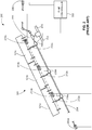
- FIG. 2 illustrates a known sensing system 200, which is implemented with a Krueger flap system 201.
- the known sensing system 200 includes drive line position sensors 202 (hereinafter 202a, 202b, etc.), a drive shaft 204, actuators 206 (hereinafter 206a, 206b, 206c, etc.), and the flaps 121 (hereinafter 121a, 121b, 121c, etc.), which are operatively coupled to the shaft 204 via corresponding arms (e.g., linkages) 212 (hereinafter 212a, 212b, 212c, etc.).
- drive line position sensors 202 hereinafter 202a, 202b, etc.
- actuators 206 hereinafter 206a, 206b, 206c, etc.
- the flaps 121 hereinafter 121a, 121b, 121c, etc.
- sensors 213 are operatively coupled to the respective flaps 121a, 121b, 121c.
- the known sensing system 200 also includes a hydraulic motor 214, an electric motor 216 and gearing 220, which may be implemented as differential in some examples. Further, the hydraulic motor 214 and the electric motor 216 are communicatively coupled to a flap controller 222 which, in turn, is communicatively coupled to the drive line position sensors 202a, 202b.
- the flap controller 222 utilizes data (e.g., positional data, rotational displacement data, etc.) received from the drive line sensors 202a, 202b to direct movement of at least one of the hydraulic motor 214, the actuators 206a, 206b 206c and/or the electric motor 216.
- data e.g., positional data, rotational displacement data, etc.
- the flap controller 222 utilizes data (e.g., positional data, rotational displacement data, etc.) received from the drive line sensors 202a, 202b to direct movement of at least one of the hydraulic motor 214, the actuators 206a, 206b 206c and/or the electric motor 216.
- data e.g., positional data, rotational displacement data, etc.
- the flap controller 222 receives angular rotation data from each of the sensors 213a, 213b, 213c.
- one of the sensors 213a, 213b, 213c is implemented for each one of the flaps 121a, 121b, 121c. Accordingly, the known sensing system 200 can be subject to malfunction when any one of the three sensors 213a, 213b, 213c fails and/or malfunctions.
- examples disclosed herein utilize instead a single sensor and/or sensor assembly to determine a condition associated with multiple movable control surfaces.
- the aforementioned single sensor is implemented with multiple differentials to enable the sensor to determine deflection(s) and/or a condition of the flaps 121a, 121b, 121c.
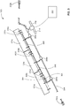
- FIG. 3 illustrates an example sensing system 300 in accordance with teachings of this disclosure.
- the sensing system 300 of the illustrated example includes a sensor (a sensor assembly) 301, differentials 302 (hereinafter 302a, 302b, 302c, etc.), and shafts 304, 306, 308.
- the sensor 301 includes pivots (e.g., linkages, pivot arms, etc.) 310 (hereinafter 310a, 310b, 310c, etc.).
- the shafts 304, 306, 308 are operatively coupled to the respective flaps 121a, 121b, 121c, as well as the respective differentials 302a, 302b, 302c.
- the drive line position sensors 202a, 202b are shown operatively coupled to the drive line shaft 204 which, in turn, is operatively coupled to the actuators 206a, 206b. 206c.
- at least one of the hydraulic motor 214 and the electric motor 216 is operatively coupled to the shaft 204 or the actuators 206a, 206b, 206c.
- at least one of the sensor, 301, the actuators 206a, 206b, 206c, the hydraulic motor 214 and/or the electric motor 216 is communicatively coupled to the flap controller 222.
- the sensor 301 of the illustrated example measures movement and/or positional change of the shaft 304 that is operatively coupled to an input of the first differential 302a.
- the first differential 302a is operatively coupled (e.g., mounted) to the flap 121a via the pivot 310a positioned at its output.
- the first differential 302a is operatively coupled between the shaft 304 and the pivot 310a.
- the shaft 306 is operatively coupled to the output of the first differential 302a and an input of the second differential 302b while the shaft 308 is operatively coupled to an output of the second differential 302b and an input of the third differential 302c.
- the pivot 310b associated with the flap 121b is coupled to the output of the second differential 302b and, thus, the second differential 302b is operatively coupled between the first differential 302a and the pivot 310b.
- the pivot 310c associated with the flap 121c is coupled to the output of the third differential 302c.
- the third differential 302c is operatively coupled between the second differential 302a and the pivot 310c Accordingly, the motions of the flaps 121a, 121b, 121c are interrelated with the differentials 302a, 302b, 302c, thereby providing a resultant displacement that can be measured at the sensor 301 via movement or displacement of the shaft 304.
- the rotational displacement of the shaft 304 indicates movement and/or a condition of not only the flap 121a, but the flaps 121b, 121c as well. Example calculations are described below in connection with FIG. 4 .
- any number of the flaps 121 or the differentials 302 can be implemented instead (e.g., two, four, five, ten, twenty, fifty, one hundred, etc.).
- inputs and outputs of the differentials 302a, 302b, 302c can vary (e.g., be reversed). In other words, stating an output and input of a differential may vary and be dependent on how mechanical input is applied.
- at least one of the differentials 302a, 302b, 302c is substituted with a gearbox.
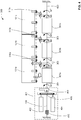
- FIG. 4 is a schematic overview of the example sensing system 300 of FIG. 3 .
- the sensing system 300 is depicted with the sensor 301, the shaft 304, the differentials 302a, 302b, 302c, the shaft 306 and the shaft 308.
- the example flap 121a is pivoted at the pivot 310a, which is coupled to an output of the differential 302a while the flap 121b is pivoted at the pivot 310b, which is coupled to an output of the differential 302b.
- the flap 121c is pivoted at the pivot 310c, which is coupled to an output of the differential 302c.
- the sensor 301 of the illustrated example includes a first rotational sensor (e.g., a rotational sub-sensor, a sensor component, etc.) 402 and a second rotational sensor 404, both of which are rotationally coupled to a pinion 406 which, in turn, is coupled to and rotates with the shaft 304.
- a first rotational sensor e.g., a rotational sub-sensor, a sensor component, etc.
- a second rotational sensor 404 both of which are rotationally coupled to a pinion 406 which, in turn, is coupled to and rotates with the shaft 304.
- an over travel arm e.g., a rotating arm
- the sensor 301 includes a spring 410, which may be implemented as a torsional spring (e.g., an anti-backlash torsional spring).
- a rotational movement of the shaft 304 at the input of the differential 302a is measured by the sensor 301 to determine a deflection of at least one of the flaps 121a, 121b, 121c and/or a condition (e.g., a rotational condition) associated with at least one of the flaps 121a, 121b, 121c.
- a condition e.g., a rotational condition
- the arrangement of the differentials 302a, 302b, 302c with the pivots 310a, 310b, 310c associated with the flaps 121a, 121b, 121c enables movement information of the flaps 121a, 121b, 121c to be obtained via measurements at a single one of the sensors 301.
- an input of the differential 302a is designated as "N1" and an output of the differential 302a is designated as "N2.”
- an input of the differential 302b is designated as “N3” and an output of the differential 302b is designated as “N4.”
- an input of the differential 302c is designated as "N5”
- an output of the differential 302c is designated as "N6”
- a rotation of a shaft 420 is designated as "N7.”
- the shaft 420 is generally stationary (e.g., the shaft 420 is fixed and does not rotate) while the pivot 310c rotates.
- Equation 5 N 3 + N 6
- N 1 N 2 + N 3
- Equation 7 relates corresponding movement of the differentials 302a, 302b, 302c to a measured resultant displacement and/or movement of the shaft 304. Accordingly, deflection(s) and/or a condition of the shaft 304 measured by the sensor 301 is represented by "N1.” In particular, displacement of the shaft 304, which is measured by the sensor 301 as the pinion 406 rotates along with the shaft 304, indicates movement of at least one of the flaps 121a, 121b, 121c.
- a sum displacement (e.g., a summed angular displacement) associated with the differentials 302a, 302b, 302c is used to determine the condition and/or displacement of the at least one of the flaps 121a, 121b, 121c.
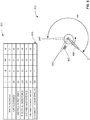
- FIGS. 5A and 5B depict normal operation of the example sensing system 300 of FIGS. 3 and 4 .
- FIG. 5A a cross-sectional view of the sensing system 300 is shown along with a table 501.
- the sensing system 300 is shown in a normal retracted position in which the flaps 121a, 121b, 121c are not displaced (e.g., a rotational angle or baseline rotation angle of 0 degrees) from a neutral (e.g., retracted) position.
- angular rotational stops 502 and 504 as well as a dotted representation 506 of the extended position of the flaps 121a, 121b, 121c, are depicted in FIG. 5A .
- the example table 501 of the illustrated example enumerates multiple scenarios of the sensing system 300
- the example table 501 relates angular measurements measured by the sensor 301 (of FIGS. 3 and 4 ) at the shaft 304.
- the scenario shown in FIG. 5 corresponds to a row 510 of the table 501 in which the outputs of the differentials 302a, 302b, 302c (e.g., "N2," “N4,” N6") are zero and, thus, the shaft 304 (shown in FIG. 3 ) has a corresponding sum displacement (e.g., "N1") of zero degrees.
- FIG. 5B depicts the example sensing system 300 in a normal extended position along with the aforementioned table 501 also shown in FIG. 5A .
- a state of the sensing system 300 corresponds to a row 520 of the table 501.
- each of the flaps 121a, 121b, 121c is displaced at 80 degrees, thereby causing a sum measurement (e.g., "N1") to be 240 degrees, which corresponds to a normal extended position of each of the flaps 121a, 121b, 121c at 80 degrees in this example.
- a sum measurement e.g., "N1”
- FIG. 6 depicts failure at a retracted position of at least one of the flaps 121a, 121b, 121c of the example sensing system 300 of FIGS. 3-5B .
- the flap 121c has failed to fully retract and its current position is depicted with solid lines in contrast to its intended position 602 (e.g., an intended rotational displacement), which corresponds to an angular displacement of 0 degrees.
- the flap 121c is depicted 10 degrees off from the intended position 602, as generally indicated by a double arrow 604.
- This failed retracted position corresponds to a row 610 of the table 501.
- the sum measurement e.g., "N1”
- the sum measurement can be 10 degrees.
- FIGS. 7A and 7B depict failure at an extended position of the example sensing system 300 of FIGS. 3-6 .
- FIG. 7A at least one of the flaps 121a, 121b, 121c is shown overextended away from an intended position 702, which is depicted by a dotted line, by 10 degrees (i.e., 90 degrees instead of the intended 80 degrees of rotational displacement).
- an arm 704 e.g., of the pivot 310 of FIG. 3
- has been brought into contact with the rotational stop 504 thereby preventing further motion of the overextended at least one of the flaps 121a, 121b, 121c.
- the table 501 is shown.
- rows 710, 712 of the table 501 correspond to measurements (e.g., measured rotations) associated with overextension of at least one of the flaps 121a, 121b, 121c, as shown in FIG. 7A .
- measurements exceeding 240 degrees at the shaft 304 can correspond to overextension failure of at least one of the flaps 121a, 121b, 121c.
- FIG. 7B the flap 121c of the example sensing system 300 is depicted in a failed extended position such that the flap 121c has under-traveled to a rotation of 70 degrees instead of an intended position 718 corresponding to 80 degrees. Accordingly, a row 720 of the table 501 indicates a measurement at the shaft 304 (shown in FIG. 3 ) that corresponds to the failed extended position of FIG. 7B .
- FIG. 8 depicts failure associated with a driveline disconnect of the example sensing system 300 of FIGS. 3-7B .
- the spring 410 (shown in FIG. 4 ) causes the shaft 304 and/or the shaft 409 (also shown in FIG. 4 ) to rotate, thereby moving the travel arm 408 toward an overtravel stop 802.
- the driveline disconnect failure causes the spring 410 to rotate the shaft 304 and/or the shaft 409 until the travel arm 408 contacts the overtravel stop 802.
- the spring 410 rotates the shaft 304 along with the travel arm 408 to a specified/pre-determined rotation that is measured by the sensor 301 to indicate a driveline disconnect failure.
- a driveline disconnect failure leads to a measured value of 280 degrees, for example.
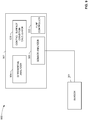
- FIG. 9 is a schematic overview of a control surface analysis system 900 that can be implemented with examples disclosed herein.
- the control surface analysis system 900 of the illustrated example includes a control surface analyzer 902 which, in turn, includes a differential analyzer 904, a control surface condition calculator 906, a sensor analyzer 908, and the flap controller 222.
- the sensor analyzer 908 is communicatively coupled to the sensor 301.
- the sensor data analyzer 908 receives data from the sensor 301 pertaining to movement of the shaft 304 (e.g., "N1"). In some examples, the sensor data analyzer 908 analyzes changes and/or angular movement (e.g., angular acceleration, angular speed, etc.) of the shaft 304 based on the aforementioned data from the sensor 301.
- data e.g., "N1"
- the sensor data analyzer 908 analyzes changes and/or angular movement (e.g., angular acceleration, angular speed, etc.) of the shaft 304 based on the aforementioned data from the sensor 301.
- the differential analyzer 904 compares the data from the sensor 301 and/or analyzed data from the sensor analyzer 908 to compare displacement readings of the sensor 301 to expected angular displacement values that correspond to different conditions of the example sensing system 300. In some examples, the differential analyzer 904 may verify that a value read by the sensor 301 corresponds to one of two values corresponding to extended and retracted positions (e.g., 0 and 240 degrees, respectively). The differential analyzer 904 may use the calculations described above in connection with FIG. 4 to analyze measurements from the sensor 213.
- the differential analyzer 904 utilizes properties (e.g., known properties) of the differentials (e.g., differential output differences, differential ratios, etc.) for the comparison of the readings from the sensor 301 to the expected angular displacement value(s).
- properties e.g., known properties
- the differentials e.g., differential output differences, differential ratios, etc.
- the control surface condition calculator 906 of the illustrated example determines a condition (e.g., an angular condition) of at least one of the flaps 121a, 121b, 121c based on the comparison performed by the differential analyzer 904. In this example, the control surface condition calculator 906 determines an existence of a failed retracted position, a failed extended position or a sensor driveline disconnect failure of the flaps 121a, 121b, 121c. Further, a table (e.g., the table 501) may be used to determine the condition (e.g., any measured values not equal or within a requisite degree of retracted or extended summed values corresponding to the flaps 121a, 121b, 121c). In some examples, the surface condition calculator 906 determines trends of the flaps 121a, 121b, 121c (e.g., gradual shifts of the flaps 121a, 121b, 121c over multiple flights).
- a condition e.g., an angular condition
- the example flap controller 222 controls a movement of the flaps 121a, 121b, 121c.
- the flap controller 222 directs movement of at least one of the hydraulic motor 214, the actuators 206a, 206b, 206c or the electric motor 216, thereby moving the flaps 121a, 121b, 121c.
- the flap controller 222 controls the movement based on a determination of the condition of the flaps 121a, 121b, 121c based on an analysis performed by the control surface condition calculator 906.
- the sensor 402 and the shaft 409 can be connected to another sensor analyzer instead of the sensor analyzer 908 to increase system availability.
- While an example manner of implementing the surface analysis system 900 of FIG. 9 is illustrated in FIG. 9 , one or more of the elements, processes and/or devices illustrated in FIG. 9 may be combined, divided, re-arranged, omitted, eliminated and/or implemented in any other way. Further, the example differential analyzer 904, the example control surface condition calculator 906, the example sensor analyzer 908, the example flap controller 222 and/or, more generally, the example control surface analysis system 900 of FIG. 9 may be implemented by hardware, software, firmware and/or any combination of hardware, software and/or firmware.
- any of the example differential analyzer 904, the example control surface condition calculator 906, the example sensor analyzer 908, the example flap controller 222 and/or, more generally, the example control surface analysis system 900 could be implemented by one or more analog or digital circuit(s), logic circuits, programmable processor(s), programmable controller(s), graphics processing unit(s) (GPU(s)), digital signal processor(s) (DSP(s)), application specific integrated circuit(s) (ASIC(s)), programmable logic device(s) (PLD(s)) and/or field programmable logic device(s) (FPLD(s)).
- At least one of the example differential analyzer 904, the example control surface condition calculator 906, the example sensor analyzer 908 and/or the example flap controller 222 is/are hereby expressly defined to include a non-transitory computer readable storage device or storage disk such as a memory, a digital versatile disk (DVD), a compact disk (CD), a Blu-ray disk, etc. including the software and/or firmware.
- the example control surface analysis system 900 of FIG. 9 may include one or more elements, processes and/or devices in addition to, or instead of, those illustrated in FIG. 9 , and/or may include more than one of any or all of the illustrated elements, processes and devices.
- the phrase "in communication,” including variations thereof, encompasses direct communication and/or indirect communication through one or more intermediary components, and does not require direct physical (e.g., wired) communication and/or constant communication, but rather additionally includes selective communication at periodic intervals, scheduled intervals, aperiodic intervals, and/or one-time events.
- FIG. 9 A flowchart representative of example hardware logic, machine readable instructions, hardware implemented state machines, and/or any combination thereof for implementing the control surface analysis system 900 of FIG. 9 is shown in FIG. 9 .
- the machine readable instructions may be one or more executable programs or portion(s) of an executable program for execution by a computer processor such as the processor 1112 shown in the example processor platform 1100 discussed below in connection with FIG. 11 .
- the program may be embodied in software stored on a non-transitory computer readable storage medium such as a CD-ROM, a floppy disk, a hard drive, a DVD, a Blu-ray disk, or a memory associated with the processor 1112, but the entire program and/or parts thereof could alternatively be executed by a device other than the processor 1112 and/or embodied in firmware or dedicated hardware.
- a non-transitory computer readable storage medium such as a CD-ROM, a floppy disk, a hard drive, a DVD, a Blu-ray disk, or a memory associated with the processor 1112
- the entire program and/or parts thereof could alternatively be executed by a device other than the processor 1112 and/or embodied in firmware or dedicated hardware.
- the example program is described with reference to the flowchart illustrated in FIG. 10 , many other methods of implementing the example control surface analysis system 900 may alternatively be used. For example, the order of execution of the blocks may be changed, and/or some of the
- any or all of the blocks may be implemented by one or more hardware circuits (e.g., discrete and/or integrated analog and/or digital circuitry, an FPGA, an ASIC, a comparator, an operational-amplifier (op-amp), a logic circuit, etc.) structured to perform the corresponding operation without executing software or firmware.
- hardware circuits e.g., discrete and/or integrated analog and/or digital circuitry, an FPGA, an ASIC, a comparator, an operational-amplifier (op-amp), a logic circuit, etc.
- the machine readable instructions described herein may be stored in one or more of a compressed format, an encrypted format, a fragmented format, a compiled format, an executable format, a packaged format, etc.
- Machine readable instructions as described herein may be stored as data (e.g., portions of instructions, code, representations of code, etc.) that may be utilized to create, manufacture, and/or produce machine executable instructions.
- the machine readable instructions may be fragmented and stored on one or more storage devices and/or computing devices (e.g., servers).
- the machine readable instructions may require one or more of installation, modification, adaptation, updating, combining, supplementing, configuring, decryption, decompression, unpacking, distribution, reassignment, compilation, etc.
- the machine readable instructions may be stored in multiple parts, which are individually compressed, encrypted, and stored on separate computing devices, wherein the parts when decrypted, decompressed, and combined form a set of executable instructions that implement a program such as that described herein.
- the machine readable instructions may be stored in a state in which they may be read by a computer, but require addition of a library (e.g., a dynamic link library (DLL)), a software development kit (SDK), an application programming interface (API), etc. in order to execute the instructions on a particular computing device or other device.
- a library e.g., a dynamic link library (DLL)
- SDK software development kit
- API application programming interface
- the machine readable instructions may need to be configured (e.g., settings stored, data input, network addresses recorded, etc.) before the machine readable instructions and/or the corresponding program(s) can be executed in whole or in part.
- the disclosed machine readable instructions and/or corresponding program(s) are intended to encompass such machine readable instructions and/or program(s) regardless of the particular format or state of the machine readable instructions and/or program(s) when stored or otherwise at rest or in transit.
- the machine readable instructions described herein can be represented by any past, present, or future instruction language, scripting language, programming language, etc.
- the machine readable instructions may be represented using any of the following languages: C, C++, Java, C#, Perl, Python, JavaScript, HyperText Markup Language (HTML), Structured Query Language (SQL), Swift, etc.
- the example processes of FIG. 10 may be implemented using executable instructions (e.g., computer and/or machine readable instructions) stored on a non-transitory computer and/or machine readable medium such as a hard disk drive, a flash memory, a read-only memory, a compact disk, a digital versatile disk, a cache, a random-access memory and/or any other storage device or storage disk in which information is stored for any duration (e.g., for extended time periods, permanently, for brief instances, for temporarily buffering, and/or for caching of the information).
- a non-transitory computer readable medium is expressly defined to include any type of computer readable storage device and/or storage disk and to exclude propagating signals and to exclude transmission media.
- A, B, and/or C refers to any combination or subset of A, B, C such as (1) A alone, (2) B alone, (3) C alone, (4) A with B, (5) A with C, (6) B with C, and (7) A with B and with C.
- the phrase "at least one of A and B" is intended to refer to implementations including any of (1) at least one A, (2) at least one B, and (3) at least one A and at least one B.
- the phrase "at least one of A or B" is intended to refer to implementations including any of (1) at least one A, (2) at least one B, and (3) at least one A and at least one B.
- the phrase "at least one of A and B" is intended to refer to implementations including any of (1) at least one A, (2) at least one B, and (3) at least one A and at least one B.
- the phrase "at least one of A or B" is intended to refer to implementations including any of (1) at least one A, (2) at least one B, and (3) at least one A and at least one B.
- the example method 1000 of FIG. 10 begins as control surfaces (e.g., the flaps 121a, 121b, 121c) are being monitored (e.g., when the control surfaces are stationary). However, the example method 1000 can be implemented when the control surfaces are moved and/or deflected.
- the sensing system 300 is being used to verify their corresponding angular displacement positions based on readings from the sensor 301. In particular, the example sensing system 300 is being used to verify whether the control surfaces have significantly deviated from their intended command positions.
- the sensor analyzer 908 and/or the sensor 301 determines an angular displacement and/or rotation associated with the shaft 304 or an input of the differential 302a.
- this displacement is associated with "N1" shown in FIG. 4 .
- the differential analyzer 904 compares the determined angular displacement of the shaft 304 with an expected value (e.g., 0 degrees, 240 degrees, etc.). In this example, the differential analyzer 904 compares the determined displacement to two known expected values. The two known expected values can correspond to an expected retracted value and an expected extended value, for example. In some examples, the differential analyzer 904 determines that the measured value is within a tolerance (e.g., within 5%) of the corresponding known expected values.
- the control surface condition analyzer 906 determines a condition of at least one of the control surfaces. In this example, the control surface condition analyzer 906 determines whether at least one of the control surfaces is deflected to a failed retracted position or a failed extended position. Additionally or alternatively, the surface condition analyzer 906 determines whether a driveline disconnect failure has occurred. In some examples, any measured displacement value that is determined to be significantly different (e.g., greater than a 5% difference) from the known expected values by the differential analyzer 904 may be determined to be a failure condition.
- FIG. 11 is a block diagram of an example processor platform 1100 structured to execute the instructions of FIG. 10 to implement the control surface analysis system 900 of FIG. 9 .
- the processor platform 1100 can be, for example, a server, a personal computer, a workstation, a self-learning machine (e.g., a neural network), a mobile device (e.g., a cell phone, a smart phone, a tablet such as an iPadTM), a personal digital assistant (PDA), an Internet appliance, a DVD player, a CD player, a digital video recorder, a Blu-ray player, a gaming console, a personal video recorder, a set top box, a headset or other wearable device, or any other type of computing device.
- a self-learning machine e.g., a neural network
- a mobile device e.g., a cell phone, a smart phone, a tablet such as an iPadTM
- PDA personal digital assistant
- an Internet appliance e.g., a DVD player
- the processor platform 1100 of the illustrated example includes a processor 1112.
- the processor 1112 of the illustrated example is hardware.
- the processor 1112 can be implemented by one or more integrated circuits, logic circuits, microprocessors, GPUs, DSPs, or controllers from any desired family or manufacturer.
- the hardware processor may be a semiconductor based (e.g., silicon based) device.
- the processor implements the example differential analyzer 904, the example control surface condition calculator 906, the example sensor analyzer 908 and the example flap controller 222.
- the processor 1112 of the illustrated example includes a local memory 1113 (e.g., a cache).
- the processor 1112 of the illustrated example is in communication with a main memory including a volatile memory 1114 and a non-volatile memory 1116 via a bus 1118.
- the volatile memory 1114 may be implemented by Synchronous Dynamic Random Access Memory (SDRAM), Dynamic Random Access Memory (DRAM), RAMBUS@ Dynamic Random Access Memory (RDRAM®) and/or any other type of random access memory device.
- the non-volatile memory 1116 may be implemented by flash memory and/or any other desired type of memory device. Access to the main memory 1114, 1116 is controlled by a memory controller.
- the processor platform 1100 of the illustrated example also includes an interface circuit 1120.
- the interface circuit 1120 may be implemented by any type of interface standard, such as an Ethernet interface, a universal serial bus (USB), a Bluetooth® interface, a near field communication (NFC) interface, and/or a PCI express interface.
- one or more input devices 1122 are connected to the interface circuit 1120.
- the input device(s) 1122 permit(s) a user to enter data and/or commands into the processor 1112.
- the input device(s) can be implemented by, for example, an audio sensor, a microphone, a camera (still or video), a keyboard, a button, a mouse, a touchscreen, a track-pad, a trackball, isopoint and/or a voice recognition system.
- One or more output devices 1124 are also connected to the interface circuit 1120 of the illustrated example.
- the output devices 1124 can be implemented, for example, by display devices (e.g., a light emitting diode (LED), an organic light emitting diode (OLED), a liquid crystal display (LCD), a cathode ray tube display (CRT), an in-place switching (IPS) display, a touchscreen, etc.), a tactile output device, a printer and/or speaker.
- the interface circuit 1120 of the illustrated example thus, typically includes a graphics driver card, a graphics driver chip and/or a graphics driver processor.
- the interface circuit 1120 of the illustrated example also includes a communication device such as a transmitter, a receiver, a transceiver, a modem, a residential gateway, a wireless access point, and/or a network interface to facilitate exchange of data with external machines (e.g., computing devices of any kind) via a network 1126.
- the communication can be via, for example, an Ethernet connection, a digital subscriber line (DSL) connection, a telephone line connection, a coaxial cable system, a satellite system, a line-of-site wireless system, a cellular telephone system, etc.
- DSL digital subscriber line
- the processor platform 1100 of the illustrated example also includes one or more mass storage devices 1128 for storing software and/or data.
- mass storage devices 1128 include floppy disk drives, hard drive disks, compact disk drives, Blu-ray disk drives, redundant array of independent disks (RAID) systems, and digital versatile disk (DVD) drives.
- the machine executable instructions 1132 of FIG. 10 may be stored in the mass storage device 1128, in the volatile memory 1114, in the non-volatile memory 1116, and/or on a removable non-transitory computer readable storage medium such as a CD or DVD.
- example methods, apparatus and articles of manufacture have been disclosed that provide a cost-effective and reliable manner to measure multiple control surfaces with a single sensor. Examples disclosed herein enable accurate determination of a condition of the control surfaces using the aforementioned sensor, thereby saving complexity, repair downtime and costs associated with implementing multiple sensors.
Landscapes
- Engineering & Computer Science (AREA)
- Aviation & Aerospace Engineering (AREA)
- Automation & Control Theory (AREA)
- Manufacturing & Machinery (AREA)
- Transportation (AREA)
- Retarders (AREA)
Abstract
Description
- This disclosure relates generally to surface deflection measurements of control surfaces, and, more particularly, to methods and apparatus to measure multiple control surfaces with a sensor.
- Angular deflections (e.g., rotational angles) of aerodynamic control surfaces can impact aerodynamic efficiency of an aircraft. In particular, aerodynamic degradation and/or relatively low performance can result from a control surface deviating from a commanded position (e.g., a commanded angular orientation). An extent to which the aerodynamic efficiency degrades can be dependent on how many control surfaces are not in their commanded position and/or an amount of angular deviation of the control surfaces relative to their commanded positions.
- Known systems use a system driveline sensor assembly to monitor multiple control surfaces. In such known systems, the control surfaces are monitored for deviations from command positions and motors are controlled to bring the control surfaces to the corresponding commanded positions. While the system is in motion (i.e., the motors are adjusting the position(s) of the control surfaces), jams and disconnects can prevent at least some of the control surfaces from reaching their commanded positions. Accordingly, individual control surfaces are monitored by respective sensors. However, these sensors can be problematic due to their complexity.
- An example apparatus for determining a condition associated with first and second control surfaces. The apparatus includes a sensor to measure a rotation of a shaft operatively coupled thereto. The apparatus also includes a first differential operatively coupled between the shaft and a first pivot of the first control surface, and a second differential operatively coupled between the first differential and a second pivot of the second control surface.
- An example aerodynamic body for use with a vehicle includes first and second control surfaces, and at least one actuator to move the first and second control surfaces. The aerodynamic body also includes first and second differentials. The first differential is operatively coupled between the shaft and a pivot associated with the first control surface. The second differential is operatively coupled between the first differential and a second pivot associated with the second control surface. The aerodynamic body also includes a rotational sensor operatively coupled to the shaft, where the rotational sensor is to measure a rotation of the shaft to determine a condition associated with the first and second control surfaces.
- An example non-transitory machine readable medium includes instructions, which when executed, cause a processor to at least determine a rotational displacement of a shaft operatively coupled to a first differential, where the first differential is operatively coupled between the shaft and a first pivot associated with a first control surface, and where a second differential is operatively coupled between the first differential and a second pivot associated with a second control surface. The instructions further cause the processor to compare the determined rotational displacement to at least one expected rotational value, and calculate a condition of at least one of the first or second control surfaces based on the comparison.
-
-
FIG. 1 is an aircraft in which examples disclosed herein can be implemented. -
FIG. 2 illustrates a known sensing system. -
FIG. 3 illustrates an example sensing system in accordance with teachings of this disclosure. -
FIG. 4 is a schematic overview of a portion of the example sensing system ofFIG. 3 . -
FIGS. 5A and5B depict normal operation of the example sensing system ofFIGS. 3 and4 . -
FIG. 6 depicts failure at a retracted position of the example sensing system ofFIGS. 3-5B . -
FIGS. 7A and7B depict failure at an extended position of the example sensing system ofFIGS. 3-6 . -
FIG. 8 depicts failure associated with a driveline disconnect of the example sensing system ofFIGS. 3-7B . -
FIG. 9 is a schematic overview of a control surface analysis system that can be implemented with examples disclosed herein. -
FIG. 10 is a flowchart representative of machine readable instructions which may be executed to implement examples disclosed herein. -
FIG. 11 is a block diagram of an example processing platform structured to execute the instructions ofFIG. 10 to implement the control surface analysis system ofFIG. 9 and/or the example sensing system ofFIG. 3 . - The figures are not to scale. Instead, the thickness of the layers or regions may be enlarged in the drawings. In general, the same reference numbers will be used throughout the drawing(s) and accompanying written description to refer to the same or like parts. As used in this patent, stating that any part is in any way on (e.g., positioned on, located on, disposed on, or formed on, etc.) another part, indicates that the referenced part is either in contact with the other part, or that the referenced part is above the other part with one or more intermediate part(s) located therebetween. Connection references (e.g., attached, coupled, connected, and joined) are to be construed broadly and may include intermediate members between a collection of elements and relative movement between elements unless otherwise indicated. As such, connection references do not necessarily infer that two elements are directly connected and in fixed relation to each other.
- Descriptors "first," "second," "third," etc. are used herein when identifying multiple elements or components which may be referred to separately. Unless otherwise specified or understood based on their context of use, such descriptors are not intended to impute any meaning of priority, physical order or arrangement in a list, or ordering in time but are merely used as labels for referring to multiple elements or components separately for ease of understanding the disclosed examples. In some examples, the descriptor "first" may be used to refer to an element in the detailed description, while the same element may be referred to in a claim with a different descriptor such as "second" or "third." In such instances, it should be understood that such descriptors are used merely for ease of referencing multiple elements or components.
- Methods and apparatus to measure multiple control surfaces with a sensor are disclosed. Some aircraft employ known system driveline sensor assemblies to monitor deflections of multiple control surfaces (e.g., flaps of a wing). In particular, these known system driveline sensor assemblies employ multiple sensors to detect positions (e.g., angular rotations) of individual corresponding control surfaces. In particular, each sensor is implemented to measure deflections of a single corresponding control surface. However, these sensors can be problematic, and integrating multiple ones of these sensors can result in significant system complexity, thereby necessitating a significant number of components, weight and cost to a vehicle.
- Examples disclosed herein provide a cost-effective, reliable and accurate manner of determining and/or measuring deflections of multiple control surfaces using a single rotational sensor (e.g., a rotational sensor assembly). Examples disclosed herein utilize a sensor operatively coupled to multiple differentials, which can be arranged across a span of an aerodynamic body (e.g., a wing, an aircraft body, a vehicle, body, etc.), for example, to determine a condition and/or deflection of multiple control surfaces. In particular, a first differential is operatively coupled between the sensor, which measures rotation, and a pivot associated with a first control surface. A second differential is operatively coupled between the first differential and a pivot associated with a second control surface. Accordingly, the rotation at the first differential is measured by the sensor to determine an angular deflection and/or a condition (e.g., an operating condition) of at least one of the first or second control surfaces. The condition may include, under-extension, over-extension, a driveline disconnect failure, etc. In some examples, a third differential is operatively coupled between the second differential and a third pivot associated with a third control surface. In some such examples, the sensor can determine an angular deflection and/or a condition associated with the third control surface.
- In some examples, the measured angular rotation is compared to at least one expected rotation value (e.g., a summed rotation value of the first, second and third differentials). The at least one expected rotation value may be an expected deflected rotation value and/or an expected retracted rotation value. In some examples, the first, second and/or third control surfaces are flaps of an aircraft. In some examples, the measured angular rotation is used to determine whether a driveline disconnect failure has occurred. In some examples, a torsional spring is operatively coupled to the sensor to rotate a shaft coupled to the first differential to a default position when the driveline disconnect failure has occurred.
- As used herein, the term "control surface" refers to a movable surface of which a translational movement, rotation and/or a deflection is varied. Accordingly, the term "control surface" can refer to an aerodynamic surface that is deflected and/or translated to affect aerodynamic properties of a vehicle, for example. As used herein, stating that a device is "coupled between" or "operatively coupled between" means that the device is functionally placed between first and second components and, thus, intervening components may be placed between the first and second components. For example, a first component is operatively coupled to an input of the device and a second component is operatively coupled to an output of the device. As used herein, the term "differential" refers to a device having an input that rotates at a different rate and/or displacement from its output.
-
FIG. 1 illustrates anexample aircraft 100 in which examples disclosed herein can be implemented. In the illustrated example, theaircraft 100 includeshorizontal tails 102, avertical tail 103 andwings 104 attached to afuselage 106. Thewings 104 of the illustrated example haveengines 107, and control surfaces (e.g., flaps, ailerons, tabs, etc.) 108, some of which are located at a trailing edge or a leading edge of thewings 104. The control surfaces 108 may be displaced or adjusted (e.g., deflected, etc.) to provide lift during takeoff, landing and/or flight maneuvers. In some examples, thecontrol surfaces 108 are operated (i.e., displaced) independently of one another. Theexample control surfaces 108 include trailing edge flaps (e.g., rotatable flaps) 114,ailerons 118,flaperons 120, leading edge Krueger flaps 121 andleading edge slats 127. In this example, thehorizontal tails 102 includeelevators 122 and thevertical tail 103 includes arudder 123. Thewings 104 also define upper and lower surfaces (e.g., upper and lower sides, upper and lower aerodynamic surfaces, etc.) 124, 126, respectively. - To control flight of the
aircraft 100, thecontrol surfaces 108 alter the lift and pitch of theaircraft 100. The control surfaces 108 of the illustrated example also play a role in controlling the speed of theaircraft 100. Any of thecontrol surfaces 108 of the illustrated example may be independently moved (e.g., deflected) to control the load distribution in different directions over thewing 104, thereby directing movement of theaircraft 100. In some examples, during cruise of theaircraft 100, thecontrol surfaces 108 are moved to reduce the drag of theaircraft 100. - Examples disclosed herein can be used to sense and/or determine a degree of movement and/or a condition of multiple movable components, such as the control surfaces 108. Examples disclosed herein may be applied to the
control surfaces 108, the Krueger flaps 121, theslats 127, theflaps 114, theailerons 118, theflaperons 120, thetails wings 104, thefuselage 106, theengines 107 and/or any other exterior or outboard structure (e.g., a horizontal stabilizer, a wing strut, an engine strut, a canard stabilizer, etc.) of theaircraft 100. Additionally or alternatively, in some examples, thefuselage 106 has control surfaces, which may be deflected, to alter the flight maneuvering characteristics during cruise and/or takeoff of theaircraft 100. -
FIG. 2 illustrates a knownsensing system 200, which is implemented with aKrueger flap system 201. The knownsensing system 200 includes drive line position sensors 202 (hereinafter 202a, 202b, etc.), adrive shaft 204, actuators 206 (hereinafter 206a, 206b, 206c, etc.), and the flaps 121 (hereinafter 121a, 121b, 121c, etc.), which are operatively coupled to theshaft 204 via corresponding arms (e.g., linkages) 212 (hereinafter 212a, 212b, 212c, etc.). In this known implementation, sensors 213 (hereinafter 213a, 213b, 213c, etc.) are operatively coupled to therespective flaps sensing system 200 also includes ahydraulic motor 214, anelectric motor 216 and gearing 220, which may be implemented as differential in some examples. Further, thehydraulic motor 214 and theelectric motor 216 are communicatively coupled to aflap controller 222 which, in turn, is communicatively coupled to the driveline position sensors - To control movement of the
flaps flap controller 222 utilizes data (e.g., positional data, rotational displacement data, etc.) received from thedrive line sensors hydraulic motor 214, theactuators electric motor 216. As a result, motion is translated from thegearing 220 to thedrive shaft 204, thereby causing thearms flaps - To determine and/or sense a position of each of the
flaps flap controller 222 receives angular rotation data from each of thesensors sensors flaps sensing system 200 can be subject to malfunction when any one of the threesensors - In contrast, examples disclosed herein utilize instead a single sensor and/or sensor assembly to determine a condition associated with multiple movable control surfaces. As will be discussed in greater detail below in connection with
FIGS. 3-11 , the aforementioned single sensor is implemented with multiple differentials to enable the sensor to determine deflection(s) and/or a condition of theflaps -
FIG. 3 illustrates anexample sensing system 300 in accordance with teachings of this disclosure. Thesensing system 300 of the illustrated example includes a sensor (a sensor assembly) 301, differentials 302 (hereinafter 302a, 302b, 302c, etc.), andshafts sensor 301 includes pivots (e.g., linkages, pivot arms, etc.) 310 (hereinafter 310a, 310b, 310c, etc.). In this example, theshafts respective flaps respective differentials line position sensors drive line shaft 204 which, in turn, is operatively coupled to theactuators hydraulic motor 214 and theelectric motor 216 is operatively coupled to theshaft 204 or theactuators actuators hydraulic motor 214 and/or theelectric motor 216 is communicatively coupled to theflap controller 222. - To determine a condition and/or a deflection of the
flaps sensor 301 of the illustrated example measures movement and/or positional change of theshaft 304 that is operatively coupled to an input of the first differential 302a. Further, the first differential 302a is operatively coupled (e.g., mounted) to theflap 121a via thepivot 310a positioned at its output. In other words, the first differential 302a is operatively coupled between theshaft 304 and thepivot 310a. Further, theshaft 306 is operatively coupled to the output of the first differential 302a and an input of the second differential 302b while theshaft 308 is operatively coupled to an output of the second differential 302b and an input of the third differential 302c. Thepivot 310b associated with theflap 121b is coupled to the output of the second differential 302b and, thus, the second differential 302b is operatively coupled between the first differential 302a and thepivot 310b. Moreover, thepivot 310c associated with theflap 121c is coupled to the output of the third differential 302c. Accordingly, the third differential 302c is operatively coupled between the second differential 302a and thepivot 310c Accordingly, the motions of theflaps differentials sensor 301 via movement or displacement of theshaft 304. In other words, the rotational displacement of theshaft 304 indicates movement and/or a condition of not only theflap 121a, but theflaps FIG. 4 . - While the example of
FIG. 3 includes three of theflaps differentials flaps 121 or the differentials 302 can be implemented instead (e.g., two, four, five, ten, twenty, fifty, one hundred, etc.). Further, inputs and outputs of thedifferentials differentials -
FIG. 4 is a schematic overview of theexample sensing system 300 ofFIG. 3 . In the illustrated example, thesensing system 300 is depicted with thesensor 301, theshaft 304, thedifferentials shaft 306 and theshaft 308. Theexample flap 121a is pivoted at thepivot 310a, which is coupled to an output of the differential 302a while theflap 121b is pivoted at thepivot 310b, which is coupled to an output of the differential 302b. Likewise, theflap 121c is pivoted at thepivot 310c, which is coupled to an output of the differential 302c. - The
sensor 301 of the illustrated example includes a first rotational sensor (e.g., a rotational sub-sensor, a sensor component, etc.) 402 and a secondrotational sensor 404, both of which are rotationally coupled to apinion 406 which, in turn, is coupled to and rotates with theshaft 304. In this example, an over travel arm (e.g., a rotating arm) 408 is coupled to aninternal shaft 409 disposed within thesensor 301 and/or theshaft 304. In some examples, thesensor 301 includes aspring 410, which may be implemented as a torsional spring (e.g., an anti-backlash torsional spring). - In operation, a rotational movement of the
shaft 304 at the input of the differential 302a is measured by thesensor 301 to determine a deflection of at least one of theflaps flaps differentials pivots flaps flaps sensors 301. As can be seen inFIG. 4 , an input of the differential 302a is designated as "N1" and an output of the differential 302a is designated as "N2." Further, an input of the differential 302b is designated as "N3" and an output of the differential 302b is designated as "N4." Further, an input of the differential 302c is designated as "N5," an output of the differential 302c is designated as "N6" and a rotation of ashaft 420 is designated as "N7." In this example, theshaft 420 is generally stationary (e.g., theshaft 420 is fixed and does not rotate) while thepivot 310c rotates. - In the illustrated example, the rotational displacement of the shaft 304 (e.g., "N1") can, therefore, be characterized by the following example Equations 1-7 below:


- Combining
Equations 1 and 2 yields Equation 3:
- Further,

- Combining Equations 3 and 4 yields Equation 5:

- Further,

- Combining Equations 5 and 6 yields Equation 7:

- In the illustrated example, Equation 7 relates corresponding movement of the
differentials shaft 304. Accordingly, deflection(s) and/or a condition of theshaft 304 measured by thesensor 301 is represented by "N1." In particular, displacement of theshaft 304, which is measured by thesensor 301 as thepinion 406 rotates along with theshaft 304, indicates movement of at least one of theflaps differentials flaps - The example calculations above are only examples and any appropriate equations and/or mathematical relationships can be employed instead. In other examples, other inputs or outputs of the
differentials flaps -
FIGS. 5A and5B depict normal operation of theexample sensing system 300 ofFIGS. 3 and4 . Turning toFIG. 5A , a cross-sectional view of thesensing system 300 is shown along with a table 501. In the illustrated example, thesensing system 300 is shown in a normal retracted position in which theflaps rotational stops dotted representation 506 of the extended position of theflaps FIG. 5A . - The example table 501 of the illustrated example enumerates multiple scenarios of the
sensing system 300 In particular, the example table 501 relates angular measurements measured by the sensor 301 (ofFIGS. 3 and4 ) at theshaft 304. The scenario shown inFIG. 5 corresponds to arow 510 of the table 501 in which the outputs of thedifferentials FIG. 3 ) has a corresponding sum displacement (e.g., "N1") of zero degrees. -
FIG. 5B depicts theexample sensing system 300 in a normal extended position along with the aforementioned table 501 also shown inFIG. 5A . In this example, a state of thesensing system 300 corresponds to arow 520 of the table 501. In particular, each of theflaps flaps -
FIG. 6 depicts failure at a retracted position of at least one of theflaps example sensing system 300 ofFIGS. 3-5B . In the illustrated example, theflap 121c has failed to fully retract and its current position is depicted with solid lines in contrast to its intended position 602 (e.g., an intended rotational displacement), which corresponds to an angular displacement of 0 degrees. Accordingly, theflap 121c is depicted 10 degrees off from the intendedposition 602, as generally indicated by adouble arrow 604. This failed retracted position corresponds to arow 610 of the table 501. In other examples, if one of theflaps -
FIGS. 7A and7B depict failure at an extended position of theexample sensing system 300 ofFIGS. 3-6 . Turning toFIG. 7A , at least one of theflaps position 702, which is depicted by a dotted line, by 10 degrees (i.e., 90 degrees instead of the intended 80 degrees of rotational displacement). In this particular example, an arm 704 (e.g., of the pivot 310 ofFIG. 3 ) has been brought into contact with therotational stop 504, thereby preventing further motion of the overextended at least one of theflaps - In this example, the table 501 is shown. In particular,
rows flaps FIG. 7A . As can be seen in the table 501, measurements exceeding 240 degrees at theshaft 304 can correspond to overextension failure of at least one of theflaps - Turning to
FIG. 7B , theflap 121c of theexample sensing system 300 is depicted in a failed extended position such that theflap 121c has under-traveled to a rotation of 70 degrees instead of an intendedposition 718 corresponding to 80 degrees. Accordingly, arow 720 of the table 501 indicates a measurement at the shaft 304 (shown inFIG. 3 ) that corresponds to the failed extended position ofFIG. 7B . -
FIG. 8 depicts failure associated with a driveline disconnect of theexample sensing system 300 ofFIGS. 3-7B . In this example, at least one of theshafts FIG. 3 ) has been disconnected and/or damaged. In the illustrated example, the spring 410 (shown inFIG. 4 ) causes theshaft 304 and/or the shaft 409 (also shown inFIG. 4 ) to rotate, thereby moving thetravel arm 408 toward anovertravel stop 802. In other words, the driveline disconnect failure causes thespring 410 to rotate theshaft 304 and/or theshaft 409 until thetravel arm 408 contacts theovertravel stop 802. Thus, thespring 410 rotates theshaft 304 along with thetravel arm 408 to a specified/pre-determined rotation that is measured by thesensor 301 to indicate a driveline disconnect failure. As can be seen in arow 810 of the table 501, a driveline disconnect failure leads to a measured value of 280 degrees, for example. -
FIG. 9 is a schematic overview of a controlsurface analysis system 900 that can be implemented with examples disclosed herein. The controlsurface analysis system 900 of the illustrated example includes acontrol surface analyzer 902 which, in turn, includes adifferential analyzer 904, a controlsurface condition calculator 906, asensor analyzer 908, and theflap controller 222. In this example, thesensor analyzer 908 is communicatively coupled to thesensor 301. - In the illustrated example, the
sensor data analyzer 908 receives data from thesensor 301 pertaining to movement of the shaft 304 (e.g., "N1"). In some examples, thesensor data analyzer 908 analyzes changes and/or angular movement (e.g., angular acceleration, angular speed, etc.) of theshaft 304 based on the aforementioned data from thesensor 301. - In this example, the
differential analyzer 904 compares the data from thesensor 301 and/or analyzed data from thesensor analyzer 908 to compare displacement readings of thesensor 301 to expected angular displacement values that correspond to different conditions of theexample sensing system 300. In some examples, thedifferential analyzer 904 may verify that a value read by thesensor 301 corresponds to one of two values corresponding to extended and retracted positions (e.g., 0 and 240 degrees, respectively). Thedifferential analyzer 904 may use the calculations described above in connection withFIG. 4 to analyze measurements from the sensor 213. In this example, thedifferential analyzer 904 utilizes properties (e.g., known properties) of the differentials (e.g., differential output differences, differential ratios, etc.) for the comparison of the readings from thesensor 301 to the expected angular displacement value(s). - The control
surface condition calculator 906 of the illustrated example determines a condition (e.g., an angular condition) of at least one of theflaps differential analyzer 904. In this example, the controlsurface condition calculator 906 determines an existence of a failed retracted position, a failed extended position or a sensor driveline disconnect failure of theflaps flaps surface condition calculator 906 determines trends of theflaps flaps - The
example flap controller 222 controls a movement of theflaps flap controller 222 directs movement of at least one of thehydraulic motor 214, theactuators electric motor 216, thereby moving theflaps flap controller 222 controls the movement based on a determination of the condition of theflaps surface condition calculator 906. In some examples, thesensor 402 and theshaft 409 can be connected to another sensor analyzer instead of thesensor analyzer 908 to increase system availability. - While an example manner of implementing the
surface analysis system 900 ofFIG. 9 is illustrated inFIG. 9 , one or more of the elements, processes and/or devices illustrated inFIG. 9 may be combined, divided, re-arranged, omitted, eliminated and/or implemented in any other way. Further, the exampledifferential analyzer 904, the example controlsurface condition calculator 906, theexample sensor analyzer 908, theexample flap controller 222 and/or, more generally, the example controlsurface analysis system 900 ofFIG. 9 may be implemented by hardware, software, firmware and/or any combination of hardware, software and/or firmware. Thus, for example, any of the exampledifferential analyzer 904, the example controlsurface condition calculator 906, theexample sensor analyzer 908, theexample flap controller 222 and/or, more generally, the example controlsurface analysis system 900 could be implemented by one or more analog or digital circuit(s), logic circuits, programmable processor(s), programmable controller(s), graphics processing unit(s) (GPU(s)), digital signal processor(s) (DSP(s)), application specific integrated circuit(s) (ASIC(s)), programmable logic device(s) (PLD(s)) and/or field programmable logic device(s) (FPLD(s)). When reading any of the apparatus or system claims of this patent to cover a purely software and/or firmware implementation, at least one of the exampledifferential analyzer 904, the example controlsurface condition calculator 906, theexample sensor analyzer 908 and/or theexample flap controller 222 is/are hereby expressly defined to include a non-transitory computer readable storage device or storage disk such as a memory, a digital versatile disk (DVD), a compact disk (CD), a Blu-ray disk, etc. including the software and/or firmware. Further still, the example controlsurface analysis system 900 ofFIG. 9 may include one or more elements, processes and/or devices in addition to, or instead of, those illustrated inFIG. 9 , and/or may include more than one of any or all of the illustrated elements, processes and devices. As used herein, the phrase "in communication," including variations thereof, encompasses direct communication and/or indirect communication through one or more intermediary components, and does not require direct physical (e.g., wired) communication and/or constant communication, but rather additionally includes selective communication at periodic intervals, scheduled intervals, aperiodic intervals, and/or one-time events. - A flowchart representative of example hardware logic, machine readable instructions, hardware implemented state machines, and/or any combination thereof for implementing the control
surface analysis system 900 ofFIG. 9 is shown inFIG. 9 . The machine readable instructions may be one or more executable programs or portion(s) of an executable program for execution by a computer processor such as theprocessor 1112 shown in theexample processor platform 1100 discussed below in connection withFIG. 11 . The program may be embodied in software stored on a non-transitory computer readable storage medium such as a CD-ROM, a floppy disk, a hard drive, a DVD, a Blu-ray disk, or a memory associated with theprocessor 1112, but the entire program and/or parts thereof could alternatively be executed by a device other than theprocessor 1112 and/or embodied in firmware or dedicated hardware. Further, although the example program is described with reference to the flowchart illustrated inFIG. 10 , many other methods of implementing the example controlsurface analysis system 900 may alternatively be used. For example, the order of execution of the blocks may be changed, and/or some of the blocks described may be changed, eliminated, or combined. Additionally or alternatively, any or all of the blocks may be implemented by one or more hardware circuits (e.g., discrete and/or integrated analog and/or digital circuitry, an FPGA, an ASIC, a comparator, an operational-amplifier (op-amp), a logic circuit, etc.) structured to perform the corresponding operation without executing software or firmware. - The machine readable instructions described herein may be stored in one or more of a compressed format, an encrypted format, a fragmented format, a compiled format, an executable format, a packaged format, etc. Machine readable instructions as described herein may be stored as data (e.g., portions of instructions, code, representations of code, etc.) that may be utilized to create, manufacture, and/or produce machine executable instructions. For example, the machine readable instructions may be fragmented and stored on one or more storage devices and/or computing devices (e.g., servers). The machine readable instructions may require one or more of installation, modification, adaptation, updating, combining, supplementing, configuring, decryption, decompression, unpacking, distribution, reassignment, compilation, etc. in order to make them directly readable, interpretable, and/or executable by a computing device and/or other machine. For example, the machine readable instructions may be stored in multiple parts, which are individually compressed, encrypted, and stored on separate computing devices, wherein the parts when decrypted, decompressed, and combined form a set of executable instructions that implement a program such as that described herein.
- In other examples, the machine readable instructions may be stored in a state in which they may be read by a computer, but require addition of a library (e.g., a dynamic link library (DLL)), a software development kit (SDK), an application programming interface (API), etc. in order to execute the instructions on a particular computing device or other device. In other examples, the machine readable instructions may need to be configured (e.g., settings stored, data input, network addresses recorded, etc.) before the machine readable instructions and/or the corresponding program(s) can be executed in whole or in part. Thus, the disclosed machine readable instructions and/or corresponding program(s) are intended to encompass such machine readable instructions and/or program(s) regardless of the particular format or state of the machine readable instructions and/or program(s) when stored or otherwise at rest or in transit.
- The machine readable instructions described herein can be represented by any past, present, or future instruction language, scripting language, programming language, etc. For example, the machine readable instructions may be represented using any of the following languages: C, C++, Java, C#, Perl, Python, JavaScript, HyperText Markup Language (HTML), Structured Query Language (SQL), Swift, etc.
- As mentioned above, the example processes of
FIG. 10 may be implemented using executable instructions (e.g., computer and/or machine readable instructions) stored on a non-transitory computer and/or machine readable medium such as a hard disk drive, a flash memory, a read-only memory, a compact disk, a digital versatile disk, a cache, a random-access memory and/or any other storage device or storage disk in which information is stored for any duration (e.g., for extended time periods, permanently, for brief instances, for temporarily buffering, and/or for caching of the information). As used herein, the term non-transitory computer readable medium is expressly defined to include any type of computer readable storage device and/or storage disk and to exclude propagating signals and to exclude transmission media. - "Including" and "comprising" (and all forms and tenses thereof) are used herein to be open ended terms. Thus, whenever a claim employs any form of "include" or "comprise" (e.g., comprises, includes, comprising, including, having, etc.) as a preamble or within a claim recitation of any kind, it is to be understood that additional elements, terms, etc. may be present without falling outside the scope of the corresponding claim or recitation. As used herein, when the phrase "at least" is used as the transition term in, for example, a preamble of a claim, it is open-ended in the same manner as the term "comprising" and "including" are open ended. The term "and/or" when used, for example, in a form such as A, B, and/or C refers to any combination or subset of A, B, C such as (1) A alone, (2) B alone, (3) C alone, (4) A with B, (5) A with C, (6) B with C, and (7) A with B and with C. As used herein in the context of describing structures, components, items, objects and/or things, the phrase "at least one of A and B" is intended to refer to implementations including any of (1) at least one A, (2) at least one B, and (3) at least one A and at least one B. Similarly, as used herein in the context of describing structures, components, items, objects and/or things, the phrase "at least one of A or B" is intended to refer to implementations including any of (1) at least one A, (2) at least one B, and (3) at least one A and at least one B. As used herein in the context of describing the performance or execution of processes, instructions, actions, activities and/or steps, the phrase "at least one of A and B" is intended to refer to implementations including any of (1) at least one A, (2) at least one B, and (3) at least one A and at least one B. Similarly, as used herein in the context of describing the performance or execution of processes, instructions, actions, activities and/or steps, the phrase "at least one of A or B" is intended to refer to implementations including any of (1) at least one A, (2) at least one B, and (3) at least one A and at least one B.
- As used herein, singular references (e.g., "a", "an", "first", "second", etc.) do not exclude a plurality. The term "a" or "an" entity, as used herein, refers to one or more of that entity. The terms "a" (or "an"), "one or more", and "at least one" can be used interchangeably herein. Furthermore, although individually listed, a plurality of means, elements or method actions may be implemented by, e.g., a single unit or processor. Additionally, although individual features may be included in different examples or claims, these may possibly be combined, and the inclusion in different examples or claims does not imply that a combination of features is not feasible and/or advantageous.
- The
example method 1000 ofFIG. 10 begins as control surfaces (e.g., theflaps example method 1000 can be implemented when the control surfaces are moved and/or deflected. In this example, thesensing system 300 is being used to verify their corresponding angular displacement positions based on readings from thesensor 301. In particular, theexample sensing system 300 is being used to verify whether the control surfaces have significantly deviated from their intended command positions. - At
block 1004, thesensor analyzer 908 and/or thesensor 301 determines an angular displacement and/or rotation associated with theshaft 304 or an input of the differential 302a. In this example, this displacement is associated with "N1" shown inFIG. 4 . - At
block 1005, thedifferential analyzer 904 compares the determined angular displacement of theshaft 304 with an expected value (e.g., 0 degrees, 240 degrees, etc.). In this example, thedifferential analyzer 904 compares the determined displacement to two known expected values. The two known expected values can correspond to an expected retracted value and an expected extended value, for example. In some examples, thedifferential analyzer 904 determines that the measured value is within a tolerance (e.g., within 5%) of the corresponding known expected values. - At
block 1006, the controlsurface condition analyzer 906 determines a condition of at least one of the control surfaces. In this example, the controlsurface condition analyzer 906 determines whether at least one of the control surfaces is deflected to a failed retracted position or a failed extended position. Additionally or alternatively, thesurface condition analyzer 906 determines whether a driveline disconnect failure has occurred. In some examples, any measured displacement value that is determined to be significantly different (e.g., greater than a 5% difference) from the known expected values by thedifferential analyzer 904 may be determined to be a failure condition. - At
block 1008, it is determined whether to repeat the process. If the process is to be repeated (block 1008), control of the process returns to block 1004. -
FIG. 11 is a block diagram of anexample processor platform 1100 structured to execute the instructions ofFIG. 10 to implement the controlsurface analysis system 900 ofFIG. 9 . Theprocessor platform 1100 can be, for example, a server, a personal computer, a workstation, a self-learning machine (e.g., a neural network), a mobile device (e.g., a cell phone, a smart phone, a tablet such as an iPad™), a personal digital assistant (PDA), an Internet appliance, a DVD player, a CD player, a digital video recorder, a Blu-ray player, a gaming console, a personal video recorder, a set top box, a headset or other wearable device, or any other type of computing device. - The
processor platform 1100 of the illustrated example includes aprocessor 1112. Theprocessor 1112 of the illustrated example is hardware. For example, theprocessor 1112 can be implemented by one or more integrated circuits, logic circuits, microprocessors, GPUs, DSPs, or controllers from any desired family or manufacturer. The hardware processor may be a semiconductor based (e.g., silicon based) device. In this example, the processor implements the exampledifferential analyzer 904, the example controlsurface condition calculator 906, theexample sensor analyzer 908 and theexample flap controller 222. - The
processor 1112 of the illustrated example includes a local memory 1113 (e.g., a cache). Theprocessor 1112 of the illustrated example is in communication with a main memory including avolatile memory 1114 and anon-volatile memory 1116 via abus 1118. Thevolatile memory 1114 may be implemented by Synchronous Dynamic Random Access Memory (SDRAM), Dynamic Random Access Memory (DRAM), RAMBUS@ Dynamic Random Access Memory (RDRAM®) and/or any other type of random access memory device. Thenon-volatile memory 1116 may be implemented by flash memory and/or any other desired type of memory device. Access to themain memory - The
processor platform 1100 of the illustrated example also includes aninterface circuit 1120. Theinterface circuit 1120 may be implemented by any type of interface standard, such as an Ethernet interface, a universal serial bus (USB), a Bluetooth® interface, a near field communication (NFC) interface, and/or a PCI express interface. - In the illustrated example, one or
more input devices 1122 are connected to theinterface circuit 1120. The input device(s) 1122 permit(s) a user to enter data and/or commands into theprocessor 1112. The input device(s) can be implemented by, for example, an audio sensor, a microphone, a camera (still or video), a keyboard, a button, a mouse, a touchscreen, a track-pad, a trackball, isopoint and/or a voice recognition system. - One or
more output devices 1124 are also connected to theinterface circuit 1120 of the illustrated example. Theoutput devices 1124 can be implemented, for example, by display devices (e.g., a light emitting diode (LED), an organic light emitting diode (OLED), a liquid crystal display (LCD), a cathode ray tube display (CRT), an in-place switching (IPS) display, a touchscreen, etc.), a tactile output device, a printer and/or speaker. Theinterface circuit 1120 of the illustrated example, thus, typically includes a graphics driver card, a graphics driver chip and/or a graphics driver processor. - The
interface circuit 1120 of the illustrated example also includes a communication device such as a transmitter, a receiver, a transceiver, a modem, a residential gateway, a wireless access point, and/or a network interface to facilitate exchange of data with external machines (e.g., computing devices of any kind) via anetwork 1126. The communication can be via, for example, an Ethernet connection, a digital subscriber line (DSL) connection, a telephone line connection, a coaxial cable system, a satellite system, a line-of-site wireless system, a cellular telephone system, etc. - The
processor platform 1100 of the illustrated example also includes one or moremass storage devices 1128 for storing software and/or data. Examples of suchmass storage devices 1128 include floppy disk drives, hard drive disks, compact disk drives, Blu-ray disk drives, redundant array of independent disks (RAID) systems, and digital versatile disk (DVD) drives. - The machine
executable instructions 1132 ofFIG. 10 may be stored in themass storage device 1128, in thevolatile memory 1114, in thenon-volatile memory 1116, and/or on a removable non-transitory computer readable storage medium such as a CD or DVD. - Example 1 includes an apparatus for determining a condition associated with first and second control surfaces. The apparatus includes a sensor to measure a rotation of a shaft operatively coupled thereto. The apparatus also includes a first differential operatively coupled between the shaft and a first pivot of the first control surface, and a second differential operatively coupled between the first differential and a second pivot of the second control surface.
- Example 2 includes the apparatus of Example 1, and further includes a third differential operatively coupled between the second differential and a third pivot of a third control surface.
- Example 3 includes the apparatus of Example 1 or 2, and further includes a processor communicatively coupled to the sensor to determine the condition based on the measured rotation of the shaft.
- Example 4 includes the apparatus of Example 3, where the processor is to determine the condition based on comparing the measured rotation to at least one expected rotational value.
- Example 5 includes the apparatus of any of Examples 1-4, and further includes a spring operatively coupled to the shaft.
- Example 6 includes the apparatus of Example 5, where the spring is to rotate the shaft to a baseline rotation when a driveline disconnect failure associated with at least one of the first or second differentials occurs.
- Example 7 includes the apparatus of any of Examples 1-6, where the first and second control surfaces are flaps for an aircraft.
- Example 8 includes an aerodynamic body for use with a vehicle. The aerodynamic body includes first and second control surfaces, at least one actuator to move the first and second control surfaces, and a shaft. The aerodynamic body also includes first and second differentials, where the first differential is operatively coupled between the shaft and a pivot associated with the first control surface, and where the second differential is operatively coupled between the first differential and a second pivot associated with the second control surface. The aerodynamic body also includes a rotational sensor operatively coupled to the shaft, where the rotational sensor is to measure a rotation of the shaft to determine a condition associated with the first and second control surfaces.
- Example 9 includes the aerodynamic body of Example 8, and further includes a processor to determine the condition based on comparing the measured rotation to at least one expected rotational value.
- Example 10 includes the aerodynamic body of Example 9, where the at least one expected rotational value includes a first rotational value corresponding to an expected value for a retracted position of the first and second control surfaces, and a second rotational value corresponding to an expected value for an extended position of the first and second control surfaces.
- Example 11 includes the aerodynamic body of any of Examples 8-10, where the aerodynamic body is a wing, and wherein the first and second control surfaces are flaps.
- Example 12 includes the aerodynamic body of Example 11, where the flaps are Krueger flaps.
- Example 13 includes the aerodynamic body of Example 11 or 12, and further includes a flap controller to vary a movement of the first and second control surfaces based on the determined condition.
- Example 14 includes the aerodynamic body of any of Examples 8-13, and further includes a spring operatively coupled to the shaft to rotate the shaft to a baseline rotation in response to a driveline disconnect failure associated with the first and second control surfaces.
- Example 15 includes a non-transitory machine readable medium includes instructions, which when executed, cause a processor to at least determine a rotational displacement of a shaft operatively coupled to a first differential, where the first differential is operatively coupled between the shaft and a first pivot associated with a first control surface, and where a second differential is operatively coupled between the first differential and a second pivot associated with a second control surface. The instructions further cause the processor to compare the determined rotational displacement to at least one expected rotational value, and calculate a condition of at least one of the first or second control surfaces based on the comparison.
- Example 16 includes the non-transitory machine readable medium of Example 15, where the instructions cause the processor to direct movement of at least one of the first or second control surfaces based on the calculated condition.
- Example 17 includes the non-transitory machine readable medium of Example 15 or 16, where the at least one expected rotational value includes a first rotational value corresponding to a retracted position of the first and second control surfaces, and a second rotational value corresponding to an extended position of the first and second control surfaces.
- Example 18 includes the non-transitory machine readable medium of any of Examples 15-17, where the condition is calculated to determine whether one of the first or second control surfaces has deviated from an intended rotational displacement.
- Example 19 includes the non-transitory machine readable medium of any of Examples 15-18, where the condition is calculated by determining a presence of a driveline disconnect failure.
- Example 20 includes the non-transitory machine readable medium of any of Examples 15-19, where the instructions cause the processor to calculate first and second rotational displacements of the first and second control surfaces, respectively, based on the rotational displacement of the shaft.
- Example 21 includes a method including determining a rotational displacement of a shaft operatively coupled to a first differential, where the first differential is operatively coupled between the shaft and a first pivot associated with a first control surface, and where a second differential is operatively coupled between the first differential and a second pivot associated with a second control surface. The method also includes comparing the determined rotational displacement to at least one expected rotational value, and determining a condition of at least one of the first or second control surfaces based on the comparison.
- Example 22 includes the method of Example 21, and further includes directing movement of at least one of the first or second control surfaces based on the determined condition.
- Example 23 includes the method of Example 21 or 22, where the at least one expected rotational value includes a first rotational value corresponding to a retracted position of the first and second control surfaces, and a second rotational value corresponding to an extended position of the first and second control surfaces.
- Example 24 includes the method of any of Examples 21-23, where determining the condition includes determining whether one of the first or second control surfaces has deviated from an intended rotational displacement.
- Example 25 includes the method of any of Examples 21-24, where determining the condition includes determining a presence of a driveline disconnect failure.
- Example 26 includes an apparatus comprising first and second control surfaces, a first differential operatively coupled between a shaft and a first pivot of the first control surface, and a second differential operatively coupled between the first differential and a second pivot of the second control surface. The apparatus also comprises a sensor coupled to the shaft and wherein the sensor is configured to measure a rotation of the shaft.
- Example 27 includes the apparatus of Example 26, and further comprises a computer processor communicatively coupled to the sensor. The computer processor is configured to determine a condition associated with the first and second control surfaces based on comparing the measured rotation of the shaft to at least one expected rotational value.
- Example 28 includes the apparatus of Example 27, and the at least one expected rotational value is or includes a summed rotation value of the first differential and the second differential.
- Example 29 includes the apparatus of Example 27 or 28, where the condition is determined to be an under-extension when the measured rotation is less than the at least one expected rotational value, and the condition is determined to be an over-extension when the measured rotation is more than the at least one expected rotational value.
- Example 30 includes the apparatus of any of Examples 27 to 29, where the at least one expected rotational value includes a first rotational value corresponding to an expected value for a retracted position of the first and second control surfaces, and a second rotational value corresponding to an expected value for an extended position of the first and second control surfaces.
- Example 31 includes the apparatus of any of Examples 27 to 30, and further comprises a third differential operatively coupled between the second differential and a third pivot of a third control surface. The computer processor is configured to determine a condition associated with the first, second and third control surfaces based on comparing the measured rotation of the shaft to at least one expected rotational value.
- Example 32 includes the apparatus of Example 31, where the at least one expected rotational value is or includes a summed rotation value of the first, second and third differentials.
- Example 33 includes the apparatus of Example 31 or 32, where the at least one expected rotational value includes a first rotational value corresponding to an expected value for a retracted position of the first, second and third control surfaces, and a second rotational value corresponding to an expected value for an extended position of the first, second and control surfaces.
- Example 34 includes the apparatus of any of Examples 27 to 33, and further includes a spring operatively coupled to the shaft.
- Example 35 includes the apparatus of Example 34, where the spring is configured to rotate the shaft to a baseline rotation when a driveline disconnect failure associated with the first and/or second differential occurs.
- Example 36 includes the apparatus of Example 35, where the at least one expected rotational value includes the rotational value of the baseline rotation.
- Example 37 includes an aerodynamic body for use with a vehicle, such as an aircraft. The aerodynamic body comprises the apparatus of any of Examples 26 to 36, and at least one actuator to move the first and second control surfaces.
- Example 38 includes the aerodynamic body of Example 37, where the aerodynamic body is a wing, and where the first and second control surfaces are flaps.
- Example 39 includes the aerodynamic body of Example 38, where the flaps are Krueger flaps.
- Example 40 includes an aircraft comprising the aerodynamic body of any of Examples 37 to 39.
- Example 41 includes a method comprising determining a rotational displacement of a shaft operatively coupled to a first differential. The first differential is operatively coupled between the shaft and a first pivot associated with a first control surface. A second differential is operatively coupled between the first differential and a second pivot associated with a second control surface. The method comprises comparing the determined rotational displacement to at least one expected rotational value, and determining a condition of the first control surface and/or the second control surface based on the comparison.
- Example 42 includes the method of Example 41, where determining the condition includes determining that the determined rotational displacement does not correspond to at least one expected rotational value and hence the first control surface and/or the second control surface has deviated from an intended rotational displacement.
- Example 43 includes the method of Example 41 or 42, where the condition is determined to be an under-extension when the measured rotation is less than the at least one expected rotational value. The condition is determined to be an over-extension when the measured rotation is more than the at least one expected rotational value.
- Example 44 includes the method of Example 43, and further comprises directing movement of at least one of the first or second control surfaces based on the determined condition.
- Example 45 includes the method of any of Examples 41 to 44, where the at least one expected rotational value includes a first rotational value corresponding to a retracted position of the first and second control surfaces, and a second rotational value corresponding to an extended position of the first and second control surfaces.
- Example 46 includes the method of any of Examples 41 to 45, where the at least one expected rotational value includes a rotational value of a baseline rotation adopted by the shaft when urged by a spring. The spring is operatively coupled to the shaft and the spring is configured to rotate the shaft to the baseline rotation when a driveline disconnect failure associated with the first differential and/or second differential occurs.
- Example 47 includes the method of any of Examples of 41 to 46, where the first and second control surfaces comprise first and second control surfaces of an aircraft.
- Example 48 includes the method of Example 47, where the first and second control surfaces comprise flaps.
- Example 49 includes Example 48, where the flaps are Kreuger flaps.
- Example 50 includes a computer program comprising computer program instructions that, when executed by a computer processor of a controller, cause the controller to perform the method of any of Examples 41 to 49.
- Example 51 includes a computer readable medium having stored thereon the computer program instructions of Example 50.
- Example 52 includes a controller comprising a computer processor and an associated computer memory, wherein the computer memory has stored therein computer program instructions that, when executed by the computer processor, cause the controller to perform the method of any of Examples 41 to 49.
- From the foregoing, it will be appreciated that example methods, apparatus and articles of manufacture have been disclosed that provide a cost-effective and reliable manner to measure multiple control surfaces with a single sensor. Examples disclosed herein enable accurate determination of a condition of the control surfaces using the aforementioned sensor, thereby saving complexity, repair downtime and costs associated with implementing multiple sensors.
- Although certain example methods, apparatus and articles of manufacture have been disclosed herein, the scope of coverage of this patent is not limited thereto. On the contrary, this patent covers all methods, apparatus and articles of manufacture fairly falling within the scope of the claims of this patent.
Claims (15)
- An apparatus comprising:a first control surface;a second control surface;a first differential operatively coupled between a shaft and a first pivot of the first control surface;a second differential operatively coupled between the first differential and a second pivot of the second control surface; anda sensor coupled to the shaft and wherein the sensor is configured to measure a rotation of the shaft.
- The apparatus as defined in claim 1, further comprising a computer processor communicatively coupled to the sensor and configured to determine a condition associated with the first control surface and the second control surface based on comparing the measured rotation of the shaft to at least one expected rotational value and, optionally, the at least one expected rotational value is or includes a summed rotation value of the first differential and the second differential.
- The apparatus as defined in claim 2, wherein the condition is determined to be an under-extension when the measured rotation is less than the at least one expected rotational value, and the condition is determined to be an over-extension when the measured rotation is more than the at least one expected rotational value.
- The apparatus as defined in claim 2 or 3, wherein the at least one expected rotational value includes a first rotational value corresponding to an expected value for a retracted position of the first control surface and the second control surface, and a second rotational value corresponding to an expected value for an extended position of the first control surface and the second control surface.
- The apparatus of any of claims 2 to 4, further comprising a third differential operatively coupled between the second differential and a third pivot of a third control surface, and wherein the computer processor is configured to determine a condition associated with the first control surface, the second control surface and the third control surface based on comparing the measured rotation of the shaft to at least one expected rotational value and, optionally, the at least one expected rotational value is or includes a summed rotation value of the first differential, the second differential and the third differential.
- The apparatus as defined in claim 5, wherein the at least one expected rotational value includes a first rotational value corresponding to an expected value for a retracted position of the first control surface, the second control surface and the third control surface, and a second rotational value corresponding to an expected value for an extended position of the first control surface, the second control surface and the third control surface.
- The apparatus as defined in any of claims 2-6, further including a spring operatively coupled to the shaft and wherein the spring is configured to rotate the shaft to a baseline rotation when a driveline disconnect failure associated with the first differential and/or the second differential occurs and, optionally, the at least one expected rotational value includes the rotational value of the baseline rotation.
- An aerodynamic body for use with a vehicle, the aerodynamic body comprising:the apparatus of any of claims 1 to 7,at least one actuator to move the first control surface and the second control surface.
- The aerodynamic body as defined in claim 8, wherein the aerodynamic body is a wing, and wherein the first and second control surfaces are flaps, optionally Krueger flaps.
- An aircraft comprising the aerodynamic body as defined in claim 8 or 9.
- A method comprising:determining a rotational displacement of a shaft operatively coupled to a first differential, wherein the first differential is operatively coupled between the shaft and a first pivot associated with a first control surface, and wherein a second differential is operatively coupled between the first differential and a second pivot associated with a second control surface;performing a comparison by comparing the determined rotational displacement to at least one expected rotational value; anddetermining a condition of the first control surface and/or second control surface based on the comparison.
- The method as defined in claim 11, wherein determining the condition includes determining that the determined rotational displacement does not correspond to at least one expected rotational value and hence the first control surface and/or the second control surface has deviated from an intended rotational displacement.
- The method as defined in claim 11 or 12, wherein the condition is determined to be an under-extension when the measured rotation is less than the at least one expected rotational value, and the condition is determined to be an over-extension when the measured rotation is more than the at least one expected rotational value and, optionally, the method further comprises directing movement of at least one of the first or second control surfaces based on the determined condition.
- The method as defined in any of claims 11 to 13, wherein the at least one expected rotational value includes a first rotational value corresponding to a retracted position of the first control surface and the second control surface, and a second rotational value corresponding to an extended position of the first control surface and the second control surface.
- The method as defined in any of claims 11 to 14, wherein the at least one expected rotational value includes a rotational value of a baseline rotation adopted by the shaft when urged by a spring operatively coupled to the shaft that is configured to rotate the shaft to the baseline rotation when a driveline disconnect failure associated with the first differential and/or the second differential occurs.
Applications Claiming Priority (1)
| Application Number | Priority Date | Filing Date | Title |
|---|---|---|---|
| US16/457,096 US11926437B2 (en) | 2019-06-28 | 2019-06-28 | Methods and apparatus to measure multiple control surfaces with a sensor |
Publications (2)
| Publication Number | Publication Date |
|---|---|
| EP3756995A1 true EP3756995A1 (en) | 2020-12-30 |
| EP3756995B1 EP3756995B1 (en) | 2023-10-25 |
Family
ID=70681689
Family Applications (1)
| Application Number | Title | Priority Date | Filing Date |
|---|---|---|---|
| EP20173954.7A Active EP3756995B1 (en) | 2019-06-28 | 2020-05-11 | Methods and apparatus to measure multiple control surfaces with a sensor |
Country Status (3)
| Country | Link |
|---|---|
| US (1) | US11926437B2 (en) |
| EP (1) | EP3756995B1 (en) |
| CN (1) | CN112141322B (en) |
Cited By (1)
| Publication number | Priority date | Publication date | Assignee | Title |
|---|---|---|---|---|
| US12434812B2 (en) * | 2023-05-31 | 2025-10-07 | Airbus Operations Gmbh | Aerodynamic system for an aircraft |
Families Citing this family (2)
| Publication number | Priority date | Publication date | Assignee | Title |
|---|---|---|---|---|
| FR3114395B1 (en) * | 2020-09-21 | 2023-04-28 | Airbus Operations Sas | Aircraft maintenance aid system and method. |
| EP4029775B1 (en) * | 2021-01-15 | 2025-07-30 | Claverham Limited | Actuation system |
Citations (5)
| Publication number | Priority date | Publication date | Assignee | Title |
|---|---|---|---|---|
| US4892274A (en) * | 1985-08-29 | 1990-01-09 | Mbb Gmbh | Segmentized flap system |
| EP1088753A2 (en) * | 1999-09-28 | 2001-04-04 | Lucas Industries Limited | Skew detection system |
| US20110255968A1 (en) * | 2008-10-22 | 2011-10-20 | Airbus Operations Gmbh | Adjuster device for an aircraft, combination of an adjuster device and an adjuster device fault recognition function, fault-tolerant adjuster system and method for reconfiguring the adjuster system |
| EP2851284A1 (en) * | 2013-09-24 | 2015-03-25 | The Boeing Company | Variable camber flap system and method |
| EP2881714A1 (en) * | 2013-12-06 | 2015-06-10 | Rosemount Aerospace Inc. | Control surface skew detection systems |
Family Cites Families (11)
| Publication number | Priority date | Publication date | Assignee | Title |
|---|---|---|---|---|
| US6382566B1 (en) * | 1998-12-29 | 2002-05-07 | The Boeing Company | Method and apparatus for detecting skew and asymmetry of an airplane flap |
| US6824099B1 (en) * | 2003-07-10 | 2004-11-30 | The Boeing Company | Brake systems for aircraft wing flaps and other control surfaces |
| US8616080B2 (en) * | 2009-02-23 | 2013-12-31 | Parker-Hannifin Corporation | Shuttle stop force limiter |
| EP2626593B1 (en) * | 2012-02-10 | 2014-07-30 | EADS Construcciones Aeronauticas, S.A. | Electro mechanical actuator |
| EP2695810B1 (en) * | 2012-08-09 | 2016-10-19 | Airbus Operations GmbH | Drive system for control surfaces of an aircraft |
| US8944952B2 (en) * | 2013-06-21 | 2015-02-03 | Arvinmeritor Technology, Llc | Differential assembly having a clutch collar actuator mechanism |
| EP2947004B1 (en) * | 2014-05-23 | 2017-02-01 | Airbus Operations GmbH | Method for determining the position of a component in a high lift system of an aircraft, high lift system of an aircraft and aircraft |
| US10227143B2 (en) | 2014-06-12 | 2019-03-12 | The Boeing Company | Lock actuation system for aircraft |
| EP3532376A1 (en) * | 2016-10-31 | 2019-09-04 | LORD Corporation | Integrated smart sensing systems and methods |
| US10501201B2 (en) * | 2017-03-27 | 2019-12-10 | Hamilton Sundstrand Corporation | Aerodynamic control surface movement monitoring system for aircraft |
| US11097829B2 (en) * | 2018-04-13 | 2021-08-24 | The Boeing Company | Methods and apparatus to control camber |
-
2019
- 2019-06-28 US US16/457,096 patent/US11926437B2/en active Active
-
2020
- 2020-05-11 EP EP20173954.7A patent/EP3756995B1/en active Active
- 2020-06-24 CN CN202010589557.9A patent/CN112141322B/en active Active
Patent Citations (5)
| Publication number | Priority date | Publication date | Assignee | Title |
|---|---|---|---|---|
| US4892274A (en) * | 1985-08-29 | 1990-01-09 | Mbb Gmbh | Segmentized flap system |
| EP1088753A2 (en) * | 1999-09-28 | 2001-04-04 | Lucas Industries Limited | Skew detection system |
| US20110255968A1 (en) * | 2008-10-22 | 2011-10-20 | Airbus Operations Gmbh | Adjuster device for an aircraft, combination of an adjuster device and an adjuster device fault recognition function, fault-tolerant adjuster system and method for reconfiguring the adjuster system |
| EP2851284A1 (en) * | 2013-09-24 | 2015-03-25 | The Boeing Company | Variable camber flap system and method |
| EP2881714A1 (en) * | 2013-12-06 | 2015-06-10 | Rosemount Aerospace Inc. | Control surface skew detection systems |
Cited By (1)
| Publication number | Priority date | Publication date | Assignee | Title |
|---|---|---|---|---|
| US12434812B2 (en) * | 2023-05-31 | 2025-10-07 | Airbus Operations Gmbh | Aerodynamic system for an aircraft |
Also Published As
| Publication number | Publication date |
|---|---|
| CN112141322B (en) | 2024-12-06 |
| CN112141322A (en) | 2020-12-29 |
| US11926437B2 (en) | 2024-03-12 |
| EP3756995B1 (en) | 2023-10-25 |
| US20200407080A1 (en) | 2020-12-31 |
Similar Documents
| Publication | Publication Date | Title |
|---|---|---|
| EP3756995B1 (en) | Methods and apparatus to measure multiple control surfaces with a sensor | |
| US11958591B2 (en) | Flap actuation systems and related methods | |
| EP3012191B1 (en) | Method for determining a state of a component in a high lift system of an aircraft, high lift system of an aircraft and aircraft having such a high lift system | |
| CA2756781C (en) | Adjustment of wings for variable camber for optimum take-off and landing configuration | |
| US11649037B2 (en) | Low latency pitch adjustable rotors | |
| CN102175444B (en) | Device for measuring load of multiple throttle rods | |
| EP2818835A2 (en) | Control surface calibration system | |
| EP3431386A1 (en) | Methods and apparatus to adjust folding wing tips | |
| US11377196B2 (en) | Adaptive airfoils | |
| EP2530019A1 (en) | Resolver type skew sensor with gimbal attachment | |
| US11097829B2 (en) | Methods and apparatus to control camber | |
| US10216167B1 (en) | Position detection system for a slat flap lever control | |
| US20190368954A1 (en) | System for monitoring characteristics of a load-bearing rotating shaft | |
| US20150219523A1 (en) | Rotor state sensor system | |
| CA3216381C (en) | Sensor fusion controller for fault tolerant ema | |
| EP4071051B1 (en) | Spoiler actuation systems and methods for aircraft | |
| US11987345B2 (en) | Methods and apparatus for variable stiffness supports in aircraft testing | |
| US11198502B2 (en) | Methods and apparatus for redundant actuation of control surfaces | |
| CN105083534A (en) | Method for determining the position of a component in a high lift system of an aircraft, high lift system of an aircraft and aircraft | |
| CN108945517A (en) | Airplane slat inclination detection device and positioning method thereof | |
| US20220300362A1 (en) | Distributed system and diagnostic method | |
| US11970269B2 (en) | Assemblies for air vehicle control surfaces including a bullnose | |
| US10266251B2 (en) | Position sensor for electromechanical actuator | |
| US20220017209A1 (en) | Flap pressure shape biasing | |
| EP3012192A1 (en) | Method for determining a state of a component in a high lift system of an aircraft, high lift system of an aircraft and aircraft having such a high lift system |
Legal Events
| Date | Code | Title | Description |
|---|---|---|---|
| PUAI | Public reference made under article 153(3) epc to a published international application that has entered the european phase |
Free format text: ORIGINAL CODE: 0009012 |
|
| STAA | Information on the status of an ep patent application or granted ep patent |
Free format text: STATUS: THE APPLICATION HAS BEEN PUBLISHED |
|
| AK | Designated contracting states |
Kind code of ref document: A1 Designated state(s): AL AT BE BG CH CY CZ DE DK EE ES FI FR GB GR HR HU IE IS IT LI LT LU LV MC MK MT NL NO PL PT RO RS SE SI SK SM TR |
|
| AX | Request for extension of the european patent |
Extension state: BA ME |
|
| STAA | Information on the status of an ep patent application or granted ep patent |
Free format text: STATUS: REQUEST FOR EXAMINATION WAS MADE |
|
| 17P | Request for examination filed |
Effective date: 20210526 |
|
| RBV | Designated contracting states (corrected) |
Designated state(s): AL AT BE BG CH CY CZ DE DK EE ES FI FR GB GR HR HU IE IS IT LI LT LU LV MC MK MT NL NO PL PT RO RS SE SI SK SM TR |
|
| STAA | Information on the status of an ep patent application or granted ep patent |
Free format text: STATUS: EXAMINATION IS IN PROGRESS |
|
| 17Q | First examination report despatched |
Effective date: 20220314 |
|
| RAP3 | Party data changed (applicant data changed or rights of an application transferred) |
Owner name: THE BOEING COMPANY |
|
| GRAP | Despatch of communication of intention to grant a patent |
Free format text: ORIGINAL CODE: EPIDOSNIGR1 |
|
| STAA | Information on the status of an ep patent application or granted ep patent |
Free format text: STATUS: GRANT OF PATENT IS INTENDED |
|
| INTG | Intention to grant announced |
Effective date: 20230517 |
|
| P01 | Opt-out of the competence of the unified patent court (upc) registered |
Effective date: 20230612 |
|
| GRAS | Grant fee paid |
Free format text: ORIGINAL CODE: EPIDOSNIGR3 |
|
| GRAA | (expected) grant |
Free format text: ORIGINAL CODE: 0009210 |
|
| STAA | Information on the status of an ep patent application or granted ep patent |
Free format text: STATUS: THE PATENT HAS BEEN GRANTED |
|
| AK | Designated contracting states |
Kind code of ref document: B1 Designated state(s): AL AT BE BG CH CY CZ DE DK EE ES FI FR GB GR HR HU IE IS IT LI LT LU LV MC MK MT NL NO PL PT RO RS SE SI SK SM TR |
|
| REG | Reference to a national code |
Ref country code: GB Ref legal event code: FG4D |
|
| REG | Reference to a national code |
Ref country code: CH Ref legal event code: EP |
|
| REG | Reference to a national code |
Ref country code: DE Ref legal event code: R096 Ref document number: 602020019688 Country of ref document: DE |
|
| REG | Reference to a national code |
Ref country code: IE Ref legal event code: FG4D |
|
| REG | Reference to a national code |
Ref country code: LT Ref legal event code: MG9D |
|
| REG | Reference to a national code |
Ref country code: NL Ref legal event code: MP Effective date: 20231025 |
|
| REG | Reference to a national code |
Ref country code: AT Ref legal event code: MK05 Ref document number: 1624420 Country of ref document: AT Kind code of ref document: T Effective date: 20231025 |
|
| PG25 | Lapsed in a contracting state [announced via postgrant information from national office to epo] |
Ref country code: NL Free format text: LAPSE BECAUSE OF FAILURE TO SUBMIT A TRANSLATION OF THE DESCRIPTION OR TO PAY THE FEE WITHIN THE PRESCRIBED TIME-LIMIT Effective date: 20231025 |
|
| PG25 | Lapsed in a contracting state [announced via postgrant information from national office to epo] |
Ref country code: GR Free format text: LAPSE BECAUSE OF FAILURE TO SUBMIT A TRANSLATION OF THE DESCRIPTION OR TO PAY THE FEE WITHIN THE PRESCRIBED TIME-LIMIT Effective date: 20240126 |
|
| PG25 | Lapsed in a contracting state [announced via postgrant information from national office to epo] |
Ref country code: IS Free format text: LAPSE BECAUSE OF FAILURE TO SUBMIT A TRANSLATION OF THE DESCRIPTION OR TO PAY THE FEE WITHIN THE PRESCRIBED TIME-LIMIT Effective date: 20240225 |
|
| PG25 | Lapsed in a contracting state [announced via postgrant information from national office to epo] |
Ref country code: LT Free format text: LAPSE BECAUSE OF FAILURE TO SUBMIT A TRANSLATION OF THE DESCRIPTION OR TO PAY THE FEE WITHIN THE PRESCRIBED TIME-LIMIT Effective date: 20231025 |
|
| PG25 | Lapsed in a contracting state [announced via postgrant information from national office to epo] |
Ref country code: AT Free format text: LAPSE BECAUSE OF FAILURE TO SUBMIT A TRANSLATION OF THE DESCRIPTION OR TO PAY THE FEE WITHIN THE PRESCRIBED TIME-LIMIT Effective date: 20231025 |
|
| PG25 | Lapsed in a contracting state [announced via postgrant information from national office to epo] |
Ref country code: ES Free format text: LAPSE BECAUSE OF FAILURE TO SUBMIT A TRANSLATION OF THE DESCRIPTION OR TO PAY THE FEE WITHIN THE PRESCRIBED TIME-LIMIT Effective date: 20231025 |
|
| PG25 | Lapsed in a contracting state [announced via postgrant information from national office to epo] |
Ref country code: LT Free format text: LAPSE BECAUSE OF FAILURE TO SUBMIT A TRANSLATION OF THE DESCRIPTION OR TO PAY THE FEE WITHIN THE PRESCRIBED TIME-LIMIT Effective date: 20231025 Ref country code: IS Free format text: LAPSE BECAUSE OF FAILURE TO SUBMIT A TRANSLATION OF THE DESCRIPTION OR TO PAY THE FEE WITHIN THE PRESCRIBED TIME-LIMIT Effective date: 20240225 Ref country code: GR Free format text: LAPSE BECAUSE OF FAILURE TO SUBMIT A TRANSLATION OF THE DESCRIPTION OR TO PAY THE FEE WITHIN THE PRESCRIBED TIME-LIMIT Effective date: 20240126 Ref country code: ES Free format text: LAPSE BECAUSE OF FAILURE TO SUBMIT A TRANSLATION OF THE DESCRIPTION OR TO PAY THE FEE WITHIN THE PRESCRIBED TIME-LIMIT Effective date: 20231025 Ref country code: BG Free format text: LAPSE BECAUSE OF FAILURE TO SUBMIT A TRANSLATION OF THE DESCRIPTION OR TO PAY THE FEE WITHIN THE PRESCRIBED TIME-LIMIT Effective date: 20240125 Ref country code: AT Free format text: LAPSE BECAUSE OF FAILURE TO SUBMIT A TRANSLATION OF THE DESCRIPTION OR TO PAY THE FEE WITHIN THE PRESCRIBED TIME-LIMIT Effective date: 20231025 Ref country code: PT Free format text: LAPSE BECAUSE OF FAILURE TO SUBMIT A TRANSLATION OF THE DESCRIPTION OR TO PAY THE FEE WITHIN THE PRESCRIBED TIME-LIMIT Effective date: 20240226 |
|
| PG25 | Lapsed in a contracting state [announced via postgrant information from national office to epo] |
Ref country code: SE Free format text: LAPSE BECAUSE OF FAILURE TO SUBMIT A TRANSLATION OF THE DESCRIPTION OR TO PAY THE FEE WITHIN THE PRESCRIBED TIME-LIMIT Effective date: 20231025 Ref country code: RS Free format text: LAPSE BECAUSE OF FAILURE TO SUBMIT A TRANSLATION OF THE DESCRIPTION OR TO PAY THE FEE WITHIN THE PRESCRIBED TIME-LIMIT Effective date: 20231025 Ref country code: PL Free format text: LAPSE BECAUSE OF FAILURE TO SUBMIT A TRANSLATION OF THE DESCRIPTION OR TO PAY THE FEE WITHIN THE PRESCRIBED TIME-LIMIT Effective date: 20231025 Ref country code: NO Free format text: LAPSE BECAUSE OF FAILURE TO SUBMIT A TRANSLATION OF THE DESCRIPTION OR TO PAY THE FEE WITHIN THE PRESCRIBED TIME-LIMIT Effective date: 20240125 Ref country code: LV Free format text: LAPSE BECAUSE OF FAILURE TO SUBMIT A TRANSLATION OF THE DESCRIPTION OR TO PAY THE FEE WITHIN THE PRESCRIBED TIME-LIMIT Effective date: 20231025 Ref country code: HR Free format text: LAPSE BECAUSE OF FAILURE TO SUBMIT A TRANSLATION OF THE DESCRIPTION OR TO PAY THE FEE WITHIN THE PRESCRIBED TIME-LIMIT Effective date: 20231025 |
|
| PG25 | Lapsed in a contracting state [announced via postgrant information from national office to epo] |
Ref country code: DK Free format text: LAPSE BECAUSE OF FAILURE TO SUBMIT A TRANSLATION OF THE DESCRIPTION OR TO PAY THE FEE WITHIN THE PRESCRIBED TIME-LIMIT Effective date: 20231025 |
|
| PG25 | Lapsed in a contracting state [announced via postgrant information from national office to epo] |
Ref country code: CZ Free format text: LAPSE BECAUSE OF FAILURE TO SUBMIT A TRANSLATION OF THE DESCRIPTION OR TO PAY THE FEE WITHIN THE PRESCRIBED TIME-LIMIT Effective date: 20231025 |
|
| REG | Reference to a national code |
Ref country code: DE Ref legal event code: R097 Ref document number: 602020019688 Country of ref document: DE |
|
| PG25 | Lapsed in a contracting state [announced via postgrant information from national office to epo] |
Ref country code: SK Free format text: LAPSE BECAUSE OF FAILURE TO SUBMIT A TRANSLATION OF THE DESCRIPTION OR TO PAY THE FEE WITHIN THE PRESCRIBED TIME-LIMIT Effective date: 20231025 |
|
| PG25 | Lapsed in a contracting state [announced via postgrant information from national office to epo] |
Ref country code: SM Free format text: LAPSE BECAUSE OF FAILURE TO SUBMIT A TRANSLATION OF THE DESCRIPTION OR TO PAY THE FEE WITHIN THE PRESCRIBED TIME-LIMIT Effective date: 20231025 Ref country code: SK Free format text: LAPSE BECAUSE OF FAILURE TO SUBMIT A TRANSLATION OF THE DESCRIPTION OR TO PAY THE FEE WITHIN THE PRESCRIBED TIME-LIMIT Effective date: 20231025 Ref country code: RO Free format text: LAPSE BECAUSE OF FAILURE TO SUBMIT A TRANSLATION OF THE DESCRIPTION OR TO PAY THE FEE WITHIN THE PRESCRIBED TIME-LIMIT Effective date: 20231025 Ref country code: IT Free format text: LAPSE BECAUSE OF FAILURE TO SUBMIT A TRANSLATION OF THE DESCRIPTION OR TO PAY THE FEE WITHIN THE PRESCRIBED TIME-LIMIT Effective date: 20231025 Ref country code: EE Free format text: LAPSE BECAUSE OF FAILURE TO SUBMIT A TRANSLATION OF THE DESCRIPTION OR TO PAY THE FEE WITHIN THE PRESCRIBED TIME-LIMIT Effective date: 20231025 Ref country code: DK Free format text: LAPSE BECAUSE OF FAILURE TO SUBMIT A TRANSLATION OF THE DESCRIPTION OR TO PAY THE FEE WITHIN THE PRESCRIBED TIME-LIMIT Effective date: 20231025 Ref country code: CZ Free format text: LAPSE BECAUSE OF FAILURE TO SUBMIT A TRANSLATION OF THE DESCRIPTION OR TO PAY THE FEE WITHIN THE PRESCRIBED TIME-LIMIT Effective date: 20231025 |
|
| PLBE | No opposition filed within time limit |
Free format text: ORIGINAL CODE: 0009261 |
|
| STAA | Information on the status of an ep patent application or granted ep patent |
Free format text: STATUS: NO OPPOSITION FILED WITHIN TIME LIMIT |
|
| 26N | No opposition filed |
Effective date: 20240726 |
|
| PG25 | Lapsed in a contracting state [announced via postgrant information from national office to epo] |
Ref country code: SI Free format text: LAPSE BECAUSE OF FAILURE TO SUBMIT A TRANSLATION OF THE DESCRIPTION OR TO PAY THE FEE WITHIN THE PRESCRIBED TIME-LIMIT Effective date: 20231025 |
|
| PG25 | Lapsed in a contracting state [announced via postgrant information from national office to epo] |
Ref country code: SI Free format text: LAPSE BECAUSE OF FAILURE TO SUBMIT A TRANSLATION OF THE DESCRIPTION OR TO PAY THE FEE WITHIN THE PRESCRIBED TIME-LIMIT Effective date: 20231025 |
|
| REG | Reference to a national code |
Ref country code: CH Ref legal event code: PL |
|
| PG25 | Lapsed in a contracting state [announced via postgrant information from national office to epo] |
Ref country code: MC Free format text: LAPSE BECAUSE OF FAILURE TO SUBMIT A TRANSLATION OF THE DESCRIPTION OR TO PAY THE FEE WITHIN THE PRESCRIBED TIME-LIMIT Effective date: 20231025 |
|
| PG25 | Lapsed in a contracting state [announced via postgrant information from national office to epo] |
Ref country code: LU Free format text: LAPSE BECAUSE OF NON-PAYMENT OF DUE FEES Effective date: 20240511 |
|
| PG25 | Lapsed in a contracting state [announced via postgrant information from national office to epo] |
Ref country code: MC Free format text: LAPSE BECAUSE OF FAILURE TO SUBMIT A TRANSLATION OF THE DESCRIPTION OR TO PAY THE FEE WITHIN THE PRESCRIBED TIME-LIMIT Effective date: 20231025 Ref country code: LU Free format text: LAPSE BECAUSE OF NON-PAYMENT OF DUE FEES Effective date: 20240511 Ref country code: CH Free format text: LAPSE BECAUSE OF NON-PAYMENT OF DUE FEES Effective date: 20240531 |
|
| REG | Reference to a national code |
Ref country code: BE Ref legal event code: MM Effective date: 20240531 |
|
| PG25 | Lapsed in a contracting state [announced via postgrant information from national office to epo] |
Ref country code: IE Free format text: LAPSE BECAUSE OF NON-PAYMENT OF DUE FEES Effective date: 20240511 |
|
| PG25 | Lapsed in a contracting state [announced via postgrant information from national office to epo] |
Ref country code: BE Free format text: LAPSE BECAUSE OF NON-PAYMENT OF DUE FEES Effective date: 20240531 |
|
| PGFP | Annual fee paid to national office [announced via postgrant information from national office to epo] |
Ref country code: DE Payment date: 20250529 Year of fee payment: 6 |
|
| PGFP | Annual fee paid to national office [announced via postgrant information from national office to epo] |
Ref country code: GB Payment date: 20250527 Year of fee payment: 6 |
|
| PGFP | Annual fee paid to national office [announced via postgrant information from national office to epo] |
Ref country code: FR Payment date: 20250526 Year of fee payment: 6 |
|
| PG25 | Lapsed in a contracting state [announced via postgrant information from national office to epo] |
Ref country code: CY Free format text: LAPSE BECAUSE OF FAILURE TO SUBMIT A TRANSLATION OF THE DESCRIPTION OR TO PAY THE FEE WITHIN THE PRESCRIBED TIME-LIMIT; INVALID AB INITIO Effective date: 20200511 |
|
| PG25 | Lapsed in a contracting state [announced via postgrant information from national office to epo] |
Ref country code: HU Free format text: LAPSE BECAUSE OF FAILURE TO SUBMIT A TRANSLATION OF THE DESCRIPTION OR TO PAY THE FEE WITHIN THE PRESCRIBED TIME-LIMIT; INVALID AB INITIO Effective date: 20200511 |
|
| PG25 | Lapsed in a contracting state [announced via postgrant information from national office to epo] |
Ref country code: FI Free format text: LAPSE BECAUSE OF FAILURE TO SUBMIT A TRANSLATION OF THE DESCRIPTION OR TO PAY THE FEE WITHIN THE PRESCRIBED TIME-LIMIT Effective date: 20231025 |