EP3756977A1 - Steering device - Google Patents
Steering device Download PDFInfo
- Publication number
- EP3756977A1 EP3756977A1 EP20181413.4A EP20181413A EP3756977A1 EP 3756977 A1 EP3756977 A1 EP 3756977A1 EP 20181413 A EP20181413 A EP 20181413A EP 3756977 A1 EP3756977 A1 EP 3756977A1
- Authority
- EP
- European Patent Office
- Prior art keywords
- tooth surface
- surface normal
- normal force
- torque
- circuit
- Prior art date
- Legal status (The legal status is an assumption and is not a legal conclusion. Google has not performed a legal analysis and makes no representation as to the accuracy of the status listed.)
- Withdrawn
Links
- 230000007246 mechanism Effects 0.000 claims description 61
- 239000003638 chemical reducing agent Substances 0.000 claims description 34
- 238000012937 correction Methods 0.000 claims description 12
- 238000010586 diagram Methods 0.000 description 22
- 239000011159 matrix material Substances 0.000 description 18
- 230000010354 integration Effects 0.000 description 10
- 238000012986 modification Methods 0.000 description 9
- 230000004048 modification Effects 0.000 description 9
- 238000005259 measurement Methods 0.000 description 6
- 238000000034 method Methods 0.000 description 5
- 230000036316 preload Effects 0.000 description 4
- 230000009467 reduction Effects 0.000 description 4
- 230000006870 function Effects 0.000 description 3
- NAWXUBYGYWOOIX-SFHVURJKSA-N (2s)-2-[[4-[2-(2,4-diaminoquinazolin-6-yl)ethyl]benzoyl]amino]-4-methylidenepentanedioic acid Chemical compound C1=CC2=NC(N)=NC(N)=C2C=C1CCC1=CC=C(C(=O)N[C@@H](CC(=C)C(O)=O)C(O)=O)C=C1 NAWXUBYGYWOOIX-SFHVURJKSA-N 0.000 description 2
- 230000006835 compression Effects 0.000 description 2
- 238000007906 compression Methods 0.000 description 2
- 230000003993 interaction Effects 0.000 description 2
- 239000000463 material Substances 0.000 description 2
- 238000012545 processing Methods 0.000 description 2
- 230000003068 static effect Effects 0.000 description 2
- 238000006243 chemical reaction Methods 0.000 description 1
- 238000013461 design Methods 0.000 description 1
- 238000006073 displacement reaction Methods 0.000 description 1
- 238000006557 surface reaction Methods 0.000 description 1
Images



Classifications
-
- B—PERFORMING OPERATIONS; TRANSPORTING
- B62—LAND VEHICLES FOR TRAVELLING OTHERWISE THAN ON RAILS
- B62D—MOTOR VEHICLES; TRAILERS
- B62D6/00—Arrangements for automatically controlling steering depending on driving conditions sensed and responded to, e.g. control circuits
- B62D6/008—Control of feed-back to the steering input member, e.g. simulating road feel in steer-by-wire applications
-
- B—PERFORMING OPERATIONS; TRANSPORTING
- B62—LAND VEHICLES FOR TRAVELLING OTHERWISE THAN ON RAILS
- B62D—MOTOR VEHICLES; TRAILERS
- B62D5/00—Power-assisted or power-driven steering
- B62D5/04—Power-assisted or power-driven steering electrical, e.g. using an electric servo-motor connected to, or forming part of, the steering gear
- B62D5/0457—Power-assisted or power-driven steering electrical, e.g. using an electric servo-motor connected to, or forming part of, the steering gear characterised by control features of the drive means as such
- B62D5/046—Controlling the motor
-
- B—PERFORMING OPERATIONS; TRANSPORTING
- B62—LAND VEHICLES FOR TRAVELLING OTHERWISE THAN ON RAILS
- B62D—MOTOR VEHICLES; TRAILERS
- B62D1/00—Steering controls, i.e. means for initiating a change of direction of the vehicle
- B62D1/02—Steering controls, i.e. means for initiating a change of direction of the vehicle vehicle-mounted
- B62D1/16—Steering columns
- B62D1/20—Connecting steering column to steering gear
-
- B—PERFORMING OPERATIONS; TRANSPORTING
- B62—LAND VEHICLES FOR TRAVELLING OTHERWISE THAN ON RAILS
- B62D—MOTOR VEHICLES; TRAILERS
- B62D3/00—Steering gears
- B62D3/02—Steering gears mechanical
- B62D3/12—Steering gears mechanical of rack-and-pinion type
- B62D3/126—Steering gears mechanical of rack-and-pinion type characterised by the rack
-
- B—PERFORMING OPERATIONS; TRANSPORTING
- B62—LAND VEHICLES FOR TRAVELLING OTHERWISE THAN ON RAILS
- B62D—MOTOR VEHICLES; TRAILERS
- B62D5/00—Power-assisted or power-driven steering
- B62D5/04—Power-assisted or power-driven steering electrical, e.g. using an electric servo-motor connected to, or forming part of, the steering gear
- B62D5/0403—Power-assisted or power-driven steering electrical, e.g. using an electric servo-motor connected to, or forming part of, the steering gear characterised by constructional features, e.g. common housing for motor and gear box
-
- B—PERFORMING OPERATIONS; TRANSPORTING
- B62—LAND VEHICLES FOR TRAVELLING OTHERWISE THAN ON RAILS
- B62D—MOTOR VEHICLES; TRAILERS
- B62D5/00—Power-assisted or power-driven steering
- B62D5/04—Power-assisted or power-driven steering electrical, e.g. using an electric servo-motor connected to, or forming part of, the steering gear
- B62D5/0409—Electric motor acting on the steering column
-
- B—PERFORMING OPERATIONS; TRANSPORTING
- B62—LAND VEHICLES FOR TRAVELLING OTHERWISE THAN ON RAILS
- B62D—MOTOR VEHICLES; TRAILERS
- B62D5/00—Power-assisted or power-driven steering
- B62D5/04—Power-assisted or power-driven steering electrical, e.g. using an electric servo-motor connected to, or forming part of, the steering gear
- B62D5/0457—Power-assisted or power-driven steering electrical, e.g. using an electric servo-motor connected to, or forming part of, the steering gear characterised by control features of the drive means as such
- B62D5/0481—Power-assisted or power-driven steering electrical, e.g. using an electric servo-motor connected to, or forming part of, the steering gear characterised by control features of the drive means as such monitoring the steering system, e.g. failures
-
- B—PERFORMING OPERATIONS; TRANSPORTING
- B62—LAND VEHICLES FOR TRAVELLING OTHERWISE THAN ON RAILS
- B62D—MOTOR VEHICLES; TRAILERS
- B62D6/00—Arrangements for automatically controlling steering depending on driving conditions sensed and responded to, e.g. control circuits
-
- B—PERFORMING OPERATIONS; TRANSPORTING
- B62—LAND VEHICLES FOR TRAVELLING OTHERWISE THAN ON RAILS
- B62D—MOTOR VEHICLES; TRAILERS
- B62D5/00—Power-assisted or power-driven steering
- B62D5/04—Power-assisted or power-driven steering electrical, e.g. using an electric servo-motor connected to, or forming part of, the steering gear
- B62D5/0442—Conversion of rotational into longitudinal movement
- B62D5/0454—Worm gears
-
- B—PERFORMING OPERATIONS; TRANSPORTING
- B62—LAND VEHICLES FOR TRAVELLING OTHERWISE THAN ON RAILS
- B62D—MOTOR VEHICLES; TRAILERS
- B62D6/00—Arrangements for automatically controlling steering depending on driving conditions sensed and responded to, e.g. control circuits
- B62D6/002—Arrangements for automatically controlling steering depending on driving conditions sensed and responded to, e.g. control circuits computing target steering angles for front or rear wheels
- B62D6/006—Arrangements for automatically controlling steering depending on driving conditions sensed and responded to, e.g. control circuits computing target steering angles for front or rear wheels using a measured or estimated road friction coefficient
Definitions
- the present invention relates to a steering device.
- JP 2017-226318 A discloses a technique of estimating a rack axial force using information (motor current, motor angle, and steering torque) from a sensor mounted on an EPS and information (vehicle speed) from a sensor mounted on a vehicle.
- the steering device includes: a steering member; a rack shaft configured to turn turning wheels through axial movement of the rack shaft; a steering torque detector configured to detect steering torque that acts on the steering member; a column shaft coupled to the steering member; a pinion shaft that constitutes a rack-and-pinion mechanism together with the rack shaft; an intermediate shaft that couples the column shaft and the pinion shaft to each other; an electric motor; a speed reducer configured to output rotation of the electric motor to the column shaft at a reduced rotational speed; an angle detector configured to detect a rotational angle of the electric motor; a current detector configured to detect a motor current that flows through the electric motor; and an electronic control unit configured to control the electric motor.
- the electronic control unit includes a first friction torque computation circuit, a second friction torque computation circuit, a first load torque-column angle estimation circuit, a pinion angle estimation circuit, a second load torque estimation circuit, and an axial force estimation circuit.
- the first friction torque computation circuit is configured to compute first friction torque that is friction torque generated in the speed reducer.
- the second friction torque computation circuit is configured to compute second friction torque that is friction torque generated in the rack-and-pinion mechanism.
- the first load torque-column angle estimation circuit is configured to estimate first load torque that is load torque generated in the speed reducer, and a column angle that is a rotational angle of the column shaft, based on the steering torque, the motor current, the first friction torque, and the rotational angle of the electric motor.
- the pinion angle estimation circuit is configured to estimate an estimated pinion angle value that is an estimated value of a rotational angle of the pinion shaft, based on the first load torque, an estimated value of the column angle, and a rigidity coefficient of the intermediate shaft.
- the second load torque estimation circuit is configured to estimate second load torque that is load torque generated in the rack-and-pinion mechanism, based on the first load torque, the second friction torque, and the estimated pinion angle value.
- the axial force estimation circuit is configured to estimate an axial force that acts on the rack shaft, based on the second load torque.
- the first friction torque computation circuit is provided, and thus the first friction torque that is generated in the speed reducer can be estimated with precision.
- the second friction torque computation circuit is provided, and thus the second friction torque that is generated in the rack-and-pinion mechanism can be estimated with precision. Consequently, the rack axial force can be estimated with precision.
- the first friction torque computation circuit may include: a first slip speed computation circuit configured to compute a first slip speed that is a slip speed of the speed reducer; a first friction coefficient computation circuit configured to compute a first friction coefficient that is a friction coefficient of the speed reducer, based on the first slip speed; a first force computation circuit configured to compute a first tooth surface normal force that is a tooth surface normal force of the speed reducer; and a first torque computation circuit configured to compute the first friction torque using the first friction coefficient and the first tooth surface normal force.
- the first force computation circuit may include: a first one-point contact force computation circuit configured to compute a first one-point contact tooth surface normal force that is a tooth surface normal force of the speed reducer in a one-point contact state, based on the motor current, the steering torque, and the column angle; a first two-point contact force computation circuit configured to compute a first two-point contact tooth surface normal force that is a tooth surface normal force of the speed reducer in a two-point contact state; and a first maximum value selection circuit configured to select one of the first one-point contact tooth surface normal force and the first two-point contact tooth surface normal force, an absolute value of which is larger, as the first tooth surface normal force.
- the second friction torque computation circuit may include: a second slip speed computation circuit configured to compute a second slip speed that is a slip speed of the rack-and-pinion mechanism; a second friction coefficient computation circuit configured to compute a second friction coefficient that is a friction coefficient of the rack-and-pinion mechanism, based on the second slip speed; a second force computation circuit configured to compute a second tooth surface normal force that is a tooth surface normal force of the rack-and-pinion mechanism; and a second torque computation circuit configured to compute the second friction torque using the second friction coefficient and the second tooth surface normal force.
- the second force computation circuit may include: a second one-point contact force computation circuit configured to compute a second one-point contact tooth surface normal force that is a tooth surface normal force of the rack-and-pinion mechanism in a one-point contact state, based on the first load torque and the second load torque; a second two-point contact force computation circuit configured to compute a second two-point contact tooth surface normal force that is a tooth surface normal force of the rack-and-pinion mechanism in a two-point contact state; and a second maximum value selection circuit configured to select one of the second one-point contact tooth surface normal force and the second two-point contact tooth surface normal force, an absolute value of which is larger, as the second tooth surface normal force.
- the second friction torque computation circuit may include: a second slip speed computation circuit configured to compute a second slip speed that is a slip speed of the rack-and-pinion mechanism; a second friction coefficient computation circuit configured to compute a second friction coefficient that is a friction coefficient of the rack-and-pinion mechanism, based on the second slip speed; a second force computation circuit configured to compute a second tooth surface normal force that is a tooth surface normal force of the rack-and-pinion mechanism, based on the first tooth surface normal force; and a second torque computation circuit configured to compute the second friction torque using the second friction coefficient and the second tooth surface normal force.
- the second friction torque computation circuit may include: a third slip speed computation circuit configured to compute a third slip speed that is a slip speed of the rack-and-pinion mechanism; a friction coefficient computation circuit configured to compute a third friction coefficient that is a friction coefficient of the rack-and-pinion mechanism, based on the third slip speed; a one-point contact force correction circuit configured to compute a third one-point contact tooth surface normal force that is a tooth surface normal force of the rack-and-pinion mechanism in a one-point contact state, by correcting the first one-point contact tooth surface normal force; a two-point contact force correction circuit configured to compute a third two-point contact tooth surface normal force that is a tooth surface normal force of the rack-and-pinion mechanism in a two-point contact state, by correcting the first two-point contact tooth surface normal force; a third maximum value selection circuit configured to select one of the third one-point contact tooth surface normal force and the third two-point contact tooth surface normal force, an absolute value of which is larger, as a third tooth surface normal force
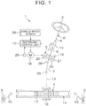
- FIG. 1 is a schematic diagram illustrating a schematic configuration of an electric power steering system to which a steering device according to an embodiment of the present invention is applied.
- An electric power steering device (steering device) 1 is a column assist-type electric power steering device (hereinafter referred to as a "column-type EPS") in which an electric motor and a speed reducer are disposed in a column portion.
- column-type EPS column assist-type electric power steering device
- the column-type EPS 1 includes a steering wheel 2 that serves as a steering member used to steer a vehicle, a steering mechanism 4 that operates in conjunction with rotation of the steering wheel 2 to turn turning wheels 3, and a steering assist mechanism 5 that assists a driver in steering.
- the steering wheel 2 and the steering mechanism 4 are mechanically coupled to each other via a steering shaft 6, a first universal joint 28, an intermediate shaft 7, and a second universal joint 29.
- the steering shaft 6 includes a first shaft 8 coupled to the steering wheel 2, and a second shaft 9 coupled to the intermediate shaft 7 via the first universal joint 28.
- the first shaft 8 and the second shaft 9 are coupled to each other so as to be relatively rotatable via a torsion bar 10.
- the second shaft 9 is an example of the "column shaft” according to the present invention.
- a torque sensor 11 is provided around the steering shaft 6.
- the torque sensor 11 detects torsion bar torque T tb , which is applied to the torsion bar 10, based on the amount of relative rotational displacement between the first shaft 8 and the second shaft 9.
- the torsion bar torque T tb which is detected by the torque sensor 11 is input to an electronic control unit (ECU) 12.
- the torque sensor 11 is an example of the "steering torque detector” according to the present invention.
- the torsion bar torque T tb is an example of the "steering torque” according to the present invention.
- the steering mechanism 4 is composed of a rack-and-pinion mechanism that includes a pinion shaft 13 and a rack shaft 14 that serves as a steered shaft.
- the turning wheels 3 are coupled to respective end portions of the rack shaft 14 via tie rods 15 and knuckle arms (not illustrated).
- the pinion shaft 13 is coupled to the intermediate shaft 7 via the second universal joint 29.
- a pinion 16 is coupled to the distal end of the pinion shaft 13.
- the rack shaft 14 extends linearly along the right-left direction of the vehicle.
- a rack 17 to be meshed with the pinion 16 is formed at an intermediate portion of the rack shaft 14 in the axial direction.
- the pinion 16 and the rack 17 constitute the rack-and-pinion mechanism, and convert rotation of the pinion shaft 13 into axial movement of the rack shaft 14.
- rotation of the steering wheel 2 is transferred to the pinion shaft 13 via the steering shaft 6 and the intermediate shaft 7.
- rotation of the pinion shaft 13 is converted into axial movement of the rack shaft 14 by the pinion 16 and the rack 17. Consequently, the turning wheels 3 are turned.
- the steering assist mechanism 5 includes an electric motor 18 that generates a steering assist force, and a speed reducer 19 that amplifies and transfers output torque from the electric motor 18 to the steering mechanism 4.
- the electric motor 18 is a three-phase brushless motor.
- the speed reducer 19 is composed of a worm gear mechanism that includes a worm gear 20 and a worm wheel 21 meshed with the worm gear 20.
- the speed reducer 19 is housed in a gear housing 22.
- the speed reduction ratio (gear ratio) of the speed reducer 19 is represented as i ww .
- the speed reduction ratio i ww is defined as the ratio ( ⁇ wg / ⁇ ww ) of a worm gear angle ⁇ wg , which is the rotational angle of the worm gear 20, to a worm wheel angle ⁇ ww , which is the rotational angle of the worm wheel 21.
- the worm wheel angle ⁇ ww is an example of the "column angle" according to the present invention.
- the worm gear 20 is rotationally driven by the electric motor 18.
- the worm wheel 21 is coupled so as to be rotatable together with the second shaft 9.
- the worm wheel 21 is rotationally driven by the worm gear 20.
- the electric motor 18 is driven in accordance with the state of steering by the driver or an instruction from an external control device such as an automatic drive system.
- the worm gear 20 is rotationally driven by the electric motor 18. Consequently, the worm wheel 21 is rotationally driven, and motor torque is applied to the steering shaft 6 to rotate the steering shaft 6 (second shaft 9). Then, rotation of the steering shaft 6 is transferred to the pinion shaft 13 via the intermediate shaft 7.
- Rotation of the pinion shaft 13 is converted into axial movement of the rack shaft 14. Consequently, the turning wheels 3 are turned. That is, the worm gear 20 is rotationally driven by the electric motor 18, which enables steering assist by the electric motor 18.
- the rotational angle of a rotor of the electric motor 18 is detected by a rotational angle sensor 25 such as a resolver.
- a vehicle speed V is detected by a vehicle speed sensor 26.
- An output signal from the rotational angle sensor 25 and the vehicle speed V which is detected by the vehicle speed sensor 26 are input to the ECU 12.
- the electric motor 18 is controlled by the ECU 12.
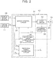
- FIG. 2 is a block diagram illustrating the electric configuration of the ECU 12.
- the ECU 12 includes a microcomputer 31, a drive circuit (three-phase inverter circuit) 32 controlled by the microcomputer 31 so as to supply electric power to the electric motor 18, and a current detector 33 that detects a current (hereinafter referred to as a "motor current") that flows through the electric motor 18.
- a motor current a current that flows through the electric motor 18.
- the microcomputer 31 includes a CPU and a memory (such as a ROM, a RAM, and a non-volatile memory), and executes a predetermined program to function as a plurality of function processing sections.
- the plurality of function processing sections include a motor control circuit 34, a rotational angle computation circuit 35, and a rack axial force estimation circuit 36.
- the rotational angle computation circuit 35 computes a rotor rotational angle ⁇ m of the electric motor 18 based on an output signal from the rotational angle sensor 25.
- the motor control circuit 34 controls drive of the drive circuit 32 based on the vehicle speed V which is detected by the vehicle speed sensor 26, the torsion bar torque T tb which is detected by the torque sensor 11, a motor current I m detected by the current detector 33, and the rotor rotational angle ⁇ m which is computed by the rotational angle computation circuit 35, for example.
- the motor control circuit 34 sets a current command value, which is a target value for the motor current I m which flows through the electric motor 18, based on the torsion bar torque T tb and the vehicle speed V.
- the current command value corresponds to a target value for a steering assist force (assist torque) that matches the vehicle state and the steering situation.
- the motor control circuit 34 controls drive of the drive circuit 32 such that the motor current which is detected by the current detector 33 is brought closer to the current command value. Consequently, appropriate steering assist that matches the vehicle state and the steering situation is achieved.
- the current command value may be set in accordance with an instruction from an external control device such as an automatic drive system.
- the rack axial force estimation circuit 36 estimates a rack axial force F r based on the motor rotational angle ⁇ m , the motor current I m , and the torsion bar torque T tb .
- an estimated value of the rack axial force F r is represented as ⁇ F r .
- FIG. 3 is a block diagram illustrating the electric configuration of the rack axial force estimation circuit 36.
- the rack axial force estimation circuit 36 includes a first multiplication circuit 41, a second multiplication circuit 42, a first observer 43, a first friction torque computation circuit 44, a pinion angle estimation circuit 45, a second observer 46, a third multiplication circuit 47, and a second friction torque computation circuit 48.
- the first observer 43 is an example of the "first load torque/column angle estimation circuit” according to the present invention.
- the second observer 46 is an example of the "second load torque estimation circuit” and the "axial force estimation circuit” according to the present invention.
- the second multiplication circuit 42 converts the rotor rotational angle ⁇ m into the rotational angle (worm wheel angle ⁇ ww ) of the second shaft 9 (worm wheel 21) by multiplying the rotor rotational angle ⁇ m by the reciprocal of the speed reduction ratio i ww of the speed reducer 19.
- the first observer 43 estimates lower shaft torque T 1s , the worm wheel angle ⁇ ww , and a worm wheel angular speed d ⁇ ww /dt based on the drive torque i ww ⁇ T m , the torsion bar torque T tb , the worm wheel angle ⁇ ww , and first friction torque T f,ww computed by the first friction torque computation circuit 44.
- the lower shaft torque T 1s is torque generated at a portion (lower shaft) of the second shaft 9 downstream of the worm wheel 21.
- the lower shaft torque T 1s is an example of the "first load torque generated in the speed reducer" according to the present invention.
- estimated values of the lower shaft torque T 1s , the worm wheel angle ⁇ ww , and the worm wheel angular speed d ⁇ ww /dt are represented as ⁇ T ls , ⁇ ⁇ ww , and d ⁇ ⁇ ww /dt, respectively.
- the first observer 43 will be discussed in detail later.
- the first friction torque computation circuit 44 computes the first friction torque T f,ww , which is generated in the speed reducer 19, based on the drive torque i ww ⁇ T m , the torsion bar torque T tb , and the estimated worm wheel angular speed value d ⁇ ⁇ ww /dt which is estimated by the first observer 43.
- the first friction torque computation circuit 44 will be discussed in detail later.
- the pinion angle estimation circuit 45 estimates a pinion angle ⁇ p , which is the rotational angle of the pinion shaft 13, based on the lower shaft torque ⁇ T ls and the estimated worm wheel angle value ⁇ ⁇ ww which are estimated by the first observer 43. In the following, an estimated value of the pinion angle ⁇ p is represented as ⁇ ⁇ p .
- the pinion angle estimation circuit 45 will be discussed in detail later.
- the second observer 46 estimates a rack axial force F r , the pinion angle ⁇ p , and a pinion angular speed d ⁇ p /dt based on the lower shaft torque ⁇ T ls which is estimated by the first observer 43, the pinion angle ⁇ ⁇ p which is estimated by the pinion angle estimation circuit 45, and second friction torque T f,rp computed by the second friction torque computation circuit 48.
- an estimated value of the rack axial force F r an estimated value of the pinion angle ⁇ p , and an estimated value of the pinion angular speed d ⁇ p /dt obtained by the second observer 46 are represented as ⁇ F r , ⁇ ⁇ p , and d ⁇ ⁇ p /dt, respectively.
- the second observer 46 will be discussed in detail later.
- the third multiplication circuit 47 computes torque (hereinafter referred to as a "torque-converted rack axial force i rp ⁇ ⁇ F r "), which acts on the second shaft 9 (worm wheel 21) because of the rack axial force ⁇ F r , by multiplying the estimated rack axial force value ⁇ F r by a gear ratio i rp of the rack-and-pinion mechanism 16, 17.
- the torque-converted rack axial force i rp ⁇ ⁇ F r is an example of the "second load torque generated in the rack-and-pinion mechanism" according to the present invention.
- the second observer 46 estimates the torque-converted rack axial force i rp ⁇ ⁇ F r , and estimates the rack axial force ⁇ F r from the torque-converted rack axial force i rp ⁇ ⁇ F r .
- the second friction torque computation circuit 48 computes the second friction torque T f,rp , which is generated in the rack-and-pinion mechanism 16, 17, based on the lower shaft torque ⁇ T 1s which is estimated by the first observer 43, the pinion angular speed d ⁇ ⁇ p /dt which is estimated by the second observer 46, and the torque-converted rack axial force i rp ⁇ ⁇ F r which is computed by the third multiplication circuit 47.
- the second friction torque computation circuit 48 will be discussed in detail later.
- FIG. 4 is a schematic diagram illustrating an example of a two-inertia model of the electric power steering system which is used for the first observer 43, the pinion angle estimation circuit 45, and the second observer 46.
- a two-inertia model 100 includes a column portion 101, a rack-and-pinion portion 102, and a spring 103 that couples the column portion 101 and the rack-and-pinion portion 102.
- the column portion 101 has a column inertia J c .
- the column inertia J c includes an inertia (worm wheel inertia) J ww of the worm wheel 21, an inertia (worm gear inertia) J wg of the worm gear 20, and an inertia (motor shaft inertia) J ms of a shaft of the electric motor 18.
- the rack-and-pinion portion 102 has a rack-and-pinion inertia J rp .
- M r is the mass of the rack shaft 14.
- S r is the stroke ratio of the rack-and-pinion mechanism 16, 17.
- the spring 103 is composed of the intermediate shaft 7.
- the spring constant (modulus of transverse elasticity) of the spring 103 is represented as k int .
- k int is an example of the "rigidity coefficient of the intermediate shaft” according to the present invention.
- the column portion 101 receives the torsion bar torque T tb from the steering wheel 2 via the torsion bar 10, and also receives the drive torque i ww ⁇ T m via the worm gear 20.
- the column portion 101 further receives the first friction torque T f,ww , which is generated in the speed reducer 19, and the lower shaft torque T 1s .
- the rack-and-pinion portion 102 receives pinion shaft torque T p , and also receives torque-converted rack axial force i rp ⁇ F r from the side of the turning wheels 3.
- the pinion shaft torque T p is torque generated at the pinion shaft 13.
- the pinion shaft torque T p is equal to the lower shaft torque Tis.
- the rack-and-pinion portion 102 further receives the second friction torque T f,rp which is generated in the rack-and-pinion mechanism 16, 17.
- the equation of motion of the two-inertia model 100 is represented by the following formulas (1), (2), and (3).
- the first observer 43 estimates the lower shaft torque T 1s , the worm wheel angle ⁇ ww , and the worm wheel angular speed d ⁇ ww /dt based on the equation of motion in the formula (1).
- the lower shaft torque T 1s is calculated by the following formula (4) which is based on the formula (1).
- T ls J c ⁇ ⁇ ww ⁇ i ww T m ⁇ T tb ⁇ T f . ww
- the state space model (extended state model) of the first observer 43 is represented by the following formula (5).
- ⁇ x ⁇ e 1 A e 1 x e 1 + B e 1 u 1
- y 1 C e 1 x e 1 + D 1 u 1
- X e1 is a state variable vector
- u 1 is a known input vector
- y 1 is an output vector (measurement value)
- a e1 is a system matrix
- B e1 is an input matrix
- C e1 is a first output matrix
- D 1 is a direct matrix.
- x e1 , u 1 , and y 1 are each represented by the following formula (6).
- x e 1 ⁇ ww ⁇ ⁇ ww T ls
- u 1 i ww T m + T tb + T f
- ww , y 1 ⁇ ww
- a e1 , B e1 , C e1 , and D 1 are each represented by the following formula (7).
- a e 1 0 1 0 0 0 1 J c 0 0 0
- B e 1 0 1 J c 0
- C e 1 1 0 0
- D 1 0
- the column inertia J c in the formula (7) is represented by the following formula (8) using the worm wheel inertia J ww , the worm gear inertia J wg , and the motor shaft inertia J ms .
- J c J ww + i ww 2 J wg + J ms
- the lower shaft torque T 1s can be estimated by applying a Luenberger state observer to the extended state model, in the same manner as a normal state observer.
- ⁇ x e1 represents an estimated value of x e1 .
- L 1 is an observer gain matrix.
- ⁇ y 1 represents an estimated value of y 1 .
- the observer gain matrix L 1 is represented by the following formula (10).
- L 1 ⁇ 3 ⁇ 1 3 ⁇ 2 1 ⁇ J c ⁇ 3 1
- ⁇ 1 [rad/sec] is a pole frequency.
- the pole frequency ⁇ 1 is set in accordance with a load desired to be compensated for by the first observer 43.
- the estimated worm wheel angular speed value d ⁇ ⁇ ww /dt is represented by the following formula (11a) using the state variable vector ⁇ x e1 .
- Ce 2 is a second output matrix, and is represented by the following formula (11b).
- the estimated lower shaft torque value ⁇ T 1s is represented by the following formula (12a) using the state variable vector ⁇ x el .
- Ce 3 is a third output matrix, and is represented by the following formula (12b).
- FIG. 5 is a block diagram illustrating the configuration of the first observer 43.
- the first observer 43 includes an A e1 multiplication circuit 51, a B e1 multiplication circuit 52, a C e1 multiplication circuit 53A, a C e2 multiplication circuit 53B, a C e3 multiplication circuit 53C, a D 1 multiplication circuit 54, a first addition circuit 55, a second addition circuit 56, an L 1 multiplication circuit 57, a third addition circuit 58, and an integration circuit 59.
- the sum (i ww ⁇ T m + T tb + T f,ww ) of the drive torque i ww ⁇ T m , the torsion bar torque T tb , and the first friction torque Tf, ww corresponds to the input vector u 1 in the formula (9), and is provided to the B e1 multiplication circuit 52 and the D 1 multiplication circuit 54.
- the worm wheel angle ⁇ ww which is computed by the second multiplication circuit 42 in FIG. 3 corresponds to the output vector (measurement value) y 1 in the formula (9), and is provided to the second addition circuit 56.
- the result of computation by the integration circuit 59 corresponds to the estimated worm wheel angle value ⁇ ⁇ ww, the estimated worm wheel angular speed value ⁇ d ⁇ ww /dt, and the estimated lower shaft torque value ⁇ T ls which are included in an estimated value ⁇ x e1 of the state variable vector x e1 .
- the initial values of the estimated values ⁇ ⁇ ww , ⁇ d ⁇ ww /dt, and ⁇ T 1s at the start of computation are 0, for example.
- the C e1 multiplication circuit 53A computes C e1 ⁇ ⁇ x e1 in the formula (9) by multiplying ⁇ x e1 , which is computed by the integration circuit 59, by C e1 .
- C e1 ⁇ ⁇ x e1 corresponds to the estimated worm wheel angle value ⁇ ⁇ ww.
- the C e2 multiplication circuit 53B computes the estimated worm wheel angular speed value ⁇ d ⁇ ww /dt (see the formula (11a)) by multiplying ⁇ x e1 by C e2 .
- the C e3 multiplication circuit 53C computes the estimated lower shaft torque value ⁇ T 1s (see the formula (12a)) by multiplying ⁇ x e1 by C e3 .
- the estimated values ⁇ ⁇ ww , ⁇ d ⁇ ww /dt, and ⁇ T ls corresponds to the outputs from the first observer 43.
- the A e1 multiplication circuit 51 computes A e1 ⁇ ⁇ x e1 in the formula (9) by multiplying ⁇ x el , which is computed by the integration circuit 59, by A e1 .
- the B e1 multiplication circuit 52 computes B e1 ⁇ u 1 in the formula (9) by multiplying (i ww ⁇ T m + T tb + T f,ww ) by B e1 .
- the D 1 multiplication circuit 54 computes D 1 ⁇ u 1 in the formula (9) by multiplying (i ww ⁇ T m + T tb + T f,ww ) by D 1 .
- D 1 is equal to 0, and thus ⁇ y 1 is equal to ⁇ ⁇ ww .
- the L 1 multiplication circuit 57 computes L 1 (y 1 - ⁇ y 1 ) in the formula (9) by multiplying the result (y 1 - ⁇ y 1 ) of computation by the second addition circuit 56 by the observer gain matrix L 1 .
- the third addition circuit 58 computes d ⁇ x e1 /dt in the formula (9) by adding the result A e1 ⁇ ⁇ x e1 of computation by the A e1 multiplication circuit 51, the result B e1 ⁇ u 1 of computation by the B e1 multiplication circuit 52, and the result L 1 (y 1 - ⁇ y 1 ) of computation by the L 1 multiplication circuit 57.
- the integration circuit 59 computes ⁇ x e1 in the formula (9) by integrating d ⁇ x e1 /dt.
- the second observer 46 estimates the rack axial force F r , the pinion angle ⁇ p , and the pinion angular speed d ⁇ pw /dt based on the equation of motion in the formula (3).
- the torque-converted value i rp ⁇ F r of the rack axial force F r is calculated by the following formula (14) which is based on the formula (3).
- i rp F r J c ⁇ ⁇ ⁇ p ⁇ T p ⁇ T f , rp
- the state space model (extended state model) of the second observer 46 is represented by the following formula (15).
- Xe2 is a state variable vector
- U2 is a known input vector
- y 2 is an output vector (measurement value)
- a e2 is a system matrix
- B e2 is an input matrix
- C e4 is a fourth output matrix
- D 2 is a direct matrix.
- X e2 , U 2 , and y 2 are each represented by the following formula (16).
- x e 2 ⁇ ⁇ p ⁇ ⁇ ⁇ p i rp F r
- a e2 , B e2 , C e4 , and D 2 are each represented by the following formula (17).
- a e 2 0 1 0 0 0 1 J rp 0 0 0
- B e 2 0 1 J rp 0
- C e 4 1 0 0
- D 2 0
- the rack-and-pinion inertia J rp in the formula (17) is represented by the following formula (18) using the rack mass M r , the stroke ratio S r of the rack-and-pinion mechanism 16, 17, and the pinion inertia J p .
- J rp M r S r 2 + J p
- the torque-converted rack axial force i rp ⁇ F r (rack shaft F r ) can be estimated by applying a Luenberger state observer to the extended state model, in the same manner as a normal state observer.
- the observer model is indicated by the following formula (19).
- ⁇ x e2 represents an estimated value of x e2 .
- L 2 is an observer gain matrix.
- ⁇ y 2 represents an estimated value of y 2 .
- the observer gain matrix L 2 is represented by the following formula (20).
- L 2 ⁇ 3 ⁇ 2 3 ⁇ 2 2 ⁇ J c ⁇ 3 2
- ⁇ 2 [rad/sec] is a pole frequency.
- the pole frequency ⁇ 2 is set in accordance with a load desired to be compensated for by the second observer 46.
- the estimated value ⁇ ⁇ p of the estimated pinion angular speed value ⁇ ⁇ p is represented by the following formula (21a) using the state variable vector ⁇ x e2 .
- C e5 is a fifth output matrix, and is represented by the following formula (21b).
- the rack axial force F r (estimated value) is represented by the following formula (22a) using the state variable vector ⁇ x e2 .
- C e6 is a sixth output matrix, and is represented by the following formula (22b).
- F ⁇ r C e 6 x ⁇ e 2
- C e 6 0 0 1 i rp
- FIG. 6 is a block diagram illustrating the configuration of the second observer 46.
- the second observer 46 includes an A e2 multiplication circuit 61, a B e2 multiplication circuit 62, a C e4 multiplication circuit 63A, a C e5 multiplication circuit 63B, a C e6 multiplication circuit 63C, a D 2 multiplication circuit 64, a first addition circuit 65, a second addition circuit 66, an L 2 multiplication circuit 67, a third addition circuit 68, and an integration circuit 69.
- the estimated pinion angle value ⁇ ⁇ p which is computed by the pinion angle estimation circuit 45 in FIG. 3 corresponds to the output vector (measurement value) y 2 in the formula (19), and is provided to the second addition circuit 66.
- the result of computation by the integration circuit 69 corresponds to the estimated pinion angle value ⁇ ⁇ p , the estimated pinion angular speed value ⁇ d ⁇ p /dt, and the estimated torque-converted rack axial force value i rp ⁇ F r which are included in the estimated value ⁇ x e2 of the state variable vector x e2 .
- the initial values of the estimated values ⁇ ⁇ p , ⁇ d ⁇ p /dt, and i rp ⁇ ⁇ F r at the start of computation are 0, for example.
- the C e4 multiplication circuit 63A computes C e4 ⁇ ⁇ x e2 in the formula (19) by multiplying ⁇ x e2 , which is computed by the integration circuit 69, by C e4 .
- C e4 ⁇ ⁇ x e2 corresponds to the estimated value ⁇ ⁇ p of the estimated pinion angle value ⁇ ⁇ p .
- the C e5 multiplication circuit 63B computes the estimated pinion angular speed value d ⁇ ⁇ p /dt (see the formula (21a)) by multiplying ⁇ x e2 by C e5 .
- the C e6 multiplication circuit 64C computes the estimated rack axial force value ⁇ F r (see the formula (22a)) by multiplying ⁇ x e2 by C e6 .
- the estimated pinion angular speed value d ⁇ ⁇ p /dt and the estimated rack axial force value ⁇ F r correspond to the outputs from the second observer 46.
- the A e2 multiplication circuit 61 computes A e2 ⁇ ⁇ x e2 in the formula (19) by multiplying ⁇ x e2 , which is computed by the integration circuit 69, by A e2 .
- the B e2 multiplication circuit 62 computes B e2 ⁇ ⁇ u 2 in the formula (19) by multiplying ( ⁇ T 1s + T f,rp- ) by B e2 .
- the D 2 multiplication circuit 64 computes D 2 ⁇ u 2 in the formula (19) by multiplying ( ⁇ T ls + T f,rp- ) by D 2 .
- D 2 is equal to 0, and thus ⁇ y 2 is equal to ⁇ ⁇ p .
- the L 2 multiplication circuit 67 computes L 2 (y 2 - ⁇ y 2 ) in the formula (19) by multiplying the result (y 2 - ⁇ y 2 ) of computation by the second addition circuit 66 by the observer gain matrix L 2 .
- the third addition circuit 68 computes d ⁇ x e2 /dt in the formula (19) by adding the result A e2 ⁇ ⁇ x e2 of computation by the A e2 multiplication circuit 61, the result B e2 ⁇ u 2 of computation by the B e2 multiplication circuit 62, and the result L 2 (y 2 - ⁇ y 2 ) of computation by the L 2 multiplication circuit 67.
- the integration circuit 69 computes ⁇ x e2 in the formula (19) by integrating d ⁇ x e2 /dt.
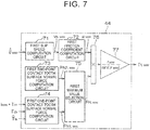
- FIG. 7 is a block diagram illustrating the electric configuration of the first friction torque computation circuit 44.
- the first friction torque computation circuit 44 includes a first slip speed computation circuit 71, a first friction coefficient computation circuit 72, a first two-point contact tooth surface normal force computation circuit 73, a first one-point contact tooth surface normal force computation circuit 74, a first maximum value selection circuit 75, a first multiplication circuit 76, and a second multiplication circuit 77.
- the first two-point contact tooth surface normal force computation circuit 73, the first one-point contact tooth surface normal force computation circuit 74, and the first maximum value selection circuit 75 are an example of the "first force computation circuit" according to the present invention.
- first two-point contact tooth surface normal force computation circuit 73 and the first one-point contact tooth surface normal force computation circuit 74 are an example of the "first two-point contact force computation circuit” and an example of the “first one-point contact force computation circuit", respectively, according to the present invention.
- the first two-point contact tooth surface normal force computation circuit 73 and the first one-point contact tooth surface normal force computation circuit 74 set a tooth surface normal force in a two-point contact state and a tooth surface normal force in a one-point contact state, respectively, using a model of meshing between a worm wheel and a worm gear.
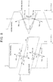
- FIG. 8 is a schematic diagram illustrating a model of meshing between a worm wheel and a worm gear.
- the suffixes "ww” and “wg” indicate the worm wheel and the worm gear, respectively.
- the x-axis and the y-axis are tangents at the point of meshing on the pitch circle of the worm wheel and the worm gear.
- the z-axis is a direction along a radial direction that is common to such gears. Rotation of the worm wheel corresponds to movement in the y direction, and rotation of the worm gear corresponds to movement in the x direction. It is assumed that a pressure angle ⁇ WW of the worm wheel is always constant. Further, it is assumed that the friction torque of the tooth surfaces acts in the direction of a lead angle ⁇ ww of the worm wheel.
- the tooth surface normal force N i,xx is generated by a material strain represented by a spring with a coefficient k c .
- T f,ww r ww sin ⁇ ww ⁇ ww F N , ww
- ⁇ ww is a friction coefficient
- r ww is the radius of the worm gear
- F N,ww is the tooth surface normal force.
- the following formula (24) represents the tooth surface contact force F c,ww which is the contact force between the tooth surfaces without the preload F 0,ww taken into consideration.
- F c , ww J ww i ww T m ⁇ i ww 2 J wg + J m T tb + T ls r ww cos ⁇ ww cos ⁇ ww Jc
- the tooth surface contact force F c,ww is a predetermined value F 0,ww /sin( ⁇ ww ) or less (F c,ww ⁇ F 0,ww /sin( ⁇ ww )).
- the tooth surface normal force F N,ww is set based on the following formula (25a).
- the tooth surface contact force F c,ww is more than the predetermined value F 0,ww /sin( ⁇ ww ) (F c,ww > F 0,ww /sin( ⁇ ww )).
- the absolute value of the tooth surface normal force F N,WW which is computed based on the formula (25a) is larger than the absolute value of the tooth surface normal force F N,WW which is computed based on the formula (25b) in the case where the contact state is the two-point contact state, and that the opposite holds true in the case where the contact state is the one-point contact state.
- one of the tooth surface normal force F N,WW which is computed based on the formula (25a) and the tooth surface normal force F N,ww which is computed based on the formula (25b), the absolute value of which is the larger corresponds to the tooth surface normal force F N,WW .
- the first two-point contact tooth surface normal force computation circuit 73 sets the tooth surface normal force F N,ww which is indicated by the formula (25a) as a tooth surface normal force F N2,ww for the two-point contact state.
- the first one-point contact tooth surface normal force computation circuit 74 sets the tooth surface normal force F N,ww which is indicated by the formula (25b) as a tooth surface normal force F N1,ww for the one-point contact state.
- the first maximum value selection circuit 75 selects one of the tooth surface normal force F N1,ww for the one-point contact state and the tooth surface normal force F N2,ww for the two-point contact state, the absolute value of which is the larger, as the final tooth surface normal force F N,ww , and provides the selected tooth surface normal force F N,ww to the first multiplication circuit 76.
- the first slip speed computation circuit 71 and the first friction coefficient computation circuit 72 estimate the friction coefficient ⁇ ww of the meshing portion between the worm wheel and the worm gear using a LuGre model. Computation of the friction coefficient ⁇ ww performed using the LuGre model is represented by the following formula (26) using a slip speed v s,ww between the two objects and a state variable z of deflection of a brush.
- ⁇ c,ww is a Coulomb friction coefficient.
- ⁇ ba,ww is a static friction coefficient.
- v stb,ww is a Stribeck velocity coefficient.
- ⁇ 0,ww is the rigidity coefficient of the brush .
- ⁇ 1,ww is the attenuation coefficient of the brush .
- ⁇ 2,ww is a viscous friction coefficient.
- the first slip speed computation circuit 71 computes the slip speed v s,ww based on the formula (27) using the estimated worm wheel angular speed value ⁇ d ⁇ ww /dt which is computed by the first observer 43 (see FIG. 3 ).
- a value d ⁇ ww /dt obtained by differentiating the worm wheel angle ⁇ ww , which is computed by the second multiplication circuit 42 (see FIG. 3 ), with respect to the time may be used in place of the estimated worm wheel angular speed value ⁇ d ⁇ ww /dt.
- the first friction coefficient computation circuit 72 computes the friction coefficient ⁇ ww based on the formula (26) using the slip speed v s,ww which is computed by the first slip speed computation circuit 71.
- the first multiplication circuit 76 multiplies the final tooth surface normal force F N,ww by the friction coefficient ⁇ ww
- the second multiplication circuit 77 computes the first friction torque T f,ww by multiplying a synthesized friction force ⁇ ww ⁇ F n,ww , which is the result of multiplication performed by the first multiplication circuit 76, by r ww /sin( ⁇ ww ).
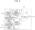
- FIG. 9 is a block diagram illustrating the electric configuration of the second friction torque computation circuit 48.
- the second friction torque computation circuit 48 includes a second slip speed computation circuit 81, a second friction coefficient computation circuit 82, a second two-point contact tooth surface normal force computation circuit 83, a second one-point contact tooth surface normal force computation circuit 84, a second maximum value selection circuit 85, a third multiplication circuit 86, and a fourth multiplication circuit 87.
- the second two-point contact tooth surface normal force computation circuit 83, the second one-point contact tooth surface normal force computation circuit 84, and the second maximum value selection circuit 85 are an example of the "second force computation circuit" according to the present invention.
- the second two-point contact tooth surface normal force computation circuit 83 and the second one-point contact tooth surface normal force computation circuit 84 are an example of the "second two-point contact force computation circuit” and an example of the “second one-point contact force computation circuit", respectively, according to the present invention.
- the second two-point contact tooth surface normal force computation circuit 83 and the second one-point contact tooth surface normal force computation circuit 84 set a tooth surface normal force with two-point contact and a tooth surface normal force with one-point contact, respectively, using a model of meshing between a rack and a pinion.
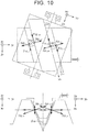
- FIG. 10 is a schematic diagram illustrating a model of meshing between a rack and a pinion.
- the suffixes "r" and “p” indicate the rack and the pinion, respectively.
- the pinion translates in the direction (y p direction) of a tangent to the pitch circle, and the rack translates in the direction (y r direction) of the rack shaft.
- a tooth of the pinion meshed with the rack is caused to contact the rack at two, right and left, points by a preload F 0,rp . This state is referred to as a "two-point contact state".
- the tooth surface normal force N i,xx is generated by a material strain represented by a spring with a coefficient k pr .
- the contact point is lost.
- a state in which one of the two contact points is lost is referred to as a "one-point contact state".
- T f,rp of the gear tooth surface is represented by the following formula (28).
- T f , rp r p sin ⁇ p ⁇ ⁇ r cos ⁇ r ⁇ rp F N , rp
- r p is the radius of the pinion
- ⁇ p is the helix angle of the pinion
- ⁇ r is the helix angle of the rack
- ⁇ rp is a friction coefficient
- F N,rp is a tooth surface normal force.
- a method of computing the tooth surface normal force F N,rp will be described below.
- ⁇ rp is a pressure angle.
- the estimated lower shaft torque value ⁇ T ls which is computed by the first observer 43 (see FIG. 3 ) is used as the pinion shaft torque T p on the right side of the formula (29).
- the torque-converted rack axial force i rp ⁇ ⁇ F r which is computed by the third multiplication circuit 47 (see FIG. 3 ) is used as the torque-converted rack axial force i rp ⁇ ⁇ F r on the right side of the formula (29).
- the tooth surface contact force F c,rp is a predetermined value F 0,rp /sin( ⁇ rp ) or less (F c,rp ⁇ F 0,rp /sin( ⁇ rp )).
- ⁇ rp is a pressure angle.
- the tooth surface normal force F N , rp is set based on the following formula (30a).
- the tooth surface contact force F c,rp is more than the predetermined value F 0,rp /sin( ⁇ rp ) (F c,rp > F 0,rp /sin( ⁇ rp )).
- the absolute value of the tooth surface normal force F N,rp which is computed based on the formula (30a) is larger than the absolute value of the tooth surface normal force F N,rp which is computed based on the formula (30b) in the case where the contact state is the two-point contact state, and that the opposite holds true in the case where the contact state is the one-point contact state.
- one of the tooth surface normal force F N,rp which is computed based on the formula (30a) and the tooth surface normal force F N,rp which is computed based on the formula (30b), the absolute value of which is the larger corresponds to the tooth surface normal force F N,rp .
- the second two-point contact tooth surface normal force computation circuit 83 sets the tooth surface normal force F N,rp which is indicated by the formula (30a) as a tooth surface normal force F N2,rp for the two-point contact state.
- the second one-point contact tooth surface normal force computation circuit 84 sets the tooth surface normal force F N,rp which is indicated by the formula (30b) as a tooth surface normal force F N1,rp for the one-point contact state.
- the second maximum value selection circuit 85 selects one of the tooth surface normal force F N1,rp for the one-point contact state and the tooth surface normal force F N2,rp for the two-point contact state, the absolute value of which is the larger, as the final tooth surface normal force F N,rp , and provides the selected tooth surface normal force F N,rp to the third multiplication circuit 86.
- the second slip speed computation circuit 81 and the second friction coefficient computation circuit 82 estimate the friction coefficient ⁇ rp of the meshing portion between the rack and the pinion using a LuGre model. Computation of the friction coefficient ⁇ rp performed using the LuGre model is represented by the following formula (31) using a slip speed v s,rp between the two objects and a state variable z of deflection of a brush.
- ⁇ c,rp is a Coulomb friction coefficient.
- ⁇ ba,rp is a static friction coefficient.
- V stb,rp is a Stribeck velocity coefficient.
- ⁇ 0,rp is the rigidity coefficient of the brush .
- ⁇ 1,rp is the attenuation coefficient of the brush.
- ⁇ 2,rp is a viscous friction coefficient.
- the second slip speed computation circuit 81 computes the slip speed v s,rp based on the formula (32) using the estimated pinion angular speed value ⁇ d ⁇ p /dt which is computed by the second observer 46 (see FIG. 3 ).
- a value d ⁇ ⁇ p /dt obtained by differentiating the estimated pinion angle value ⁇ ⁇ p , which is computed by the pinion angle estimation circuit 45 (see FIG. 3 ), with respect to the time may be used in place of the estimated pinion angular speed value d ⁇ ⁇ p /dt.
- the second friction coefficient computation circuit 82 computes the friction coefficient ⁇ rp based on the formula (31) using the slip speed v s,rp which is computed by the second slip speed computation circuit 81.
- the third multiplication circuit 86 multiplies the final tooth surface normal force F N,rp by the friction coefficient ⁇ rp .
- the fourth multiplication circuit 87 computes the second friction torque T f,rp by multiplying a synthesized friction force ⁇ rp ⁇ F N,rp , which is the result of multiplication performed by the third multiplication circuit 86, by r p sin( ⁇ p - ⁇ r )/cos(y r ).
- the first friction torque computation circuit 44 is provided, and thus the first friction torque T f,ww which is generated in the speed reducer 19 can be estimated with precision.
- the second friction torque computation circuit 48 is provided, and thus the second friction torque T f,rp which is generated in the rack-and-pinion mechanism 16, 17 can be estimated with precision. Consequently, the rack axial force F r can be estimated with precision.
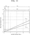
- FIG. 11 is a graph indicating the first friction torque T f,ww , which is computed by the first friction torque computation circuit 44 illustrated in FIG. 7 , and the second friction torque T f,rp , which is computed by the second friction torque computation circuit 48 illustrated in FIG. 9 , with the horizontal axis indicating motor torque and with the vertical axis indicating friction torque.
- T f,ww the first friction torque computation circuit 44 illustrated in FIG. 7
- T f,rp the second friction torque computation circuit 48 illustrated in FIG. 9
- W1 indicates the range of the first friction torque T f,ww in the one-point contact state
- W2 indicates the range of the first friction torque T f,ww in the two-point contact state
- R1 indicates the range of the second friction torque T f,rp in the one-point contact state
- R2 indicates the range of the second friction torque T f,rp in the two-point contact state.
- the second friction torque T f,rp can be estimated from the first friction torque T f,ww utilizing the correlation.
- an error may be caused in the estimation of the second friction torque T f,rp because of a phase difference between the speed reducer 19 and the rack-and-pinion mechanism 16, 17 due to the rigidity of the intermediate shaft 7 which is provided therebetween.
- the direction of the second friction torque T f,rp may not be switched because of the rigidity of the intermediate shaft 7 even if the direction of the first friction torque T f,ww is switched when the steering direction is switched. In such a case, an error may be caused in the second friction torque T f,rp which is estimated from the first friction torque T f,ww .
- the second friction torque computation circuit 48A according to the modification computes the friction coefficient ⁇ rp, which reflects the direction of friction that acts on the rack-and-pinion mechanism 16, 17, in the same manner as the second friction torque computation circuit 48 in FIG. 9 , and estimates only a tooth surface normal force that acts on the rack-and-pinion mechanism 16, 17 from a tooth surface normal force that acts on the speed reducer 19. Then, the second friction torque computation circuit 48A computes the second friction torque T f , rp by multiplying the thus computed or estimated friction coefficient ⁇ rp and tooth surface normal force and multiplying the result of the multiplication by a predetermined value.
- FIG. 12 is a block diagram illustrating the configuration of the first friction torque computation circuit 44 and the second friction torque computation circuit 48A according to the modification.
- the first friction torque computation circuit 44 is the same as the first friction torque computation circuit 44 in FIG. 7 .
- the second friction torque computation circuit 48A includes a second slip speed computation circuit 81, a second friction coefficient computation circuit 82, a two-point contact tooth surface normal force correction circuit 91, a one-point contact tooth surface normal force correction circuit 92, a third maximum value selection circuit 93, a fifth multiplication circuit 94, and a sixth multiplication circuit 95.
- the second slip speed computation circuit 81 and the second friction coefficient computation circuit 82 are the same as the second slip speed computation circuit 81 and the second friction coefficient computation circuit 82, respectively, in FIG. 9 , and thus are not described.
- the second slip speed computation circuit 81 and the second friction coefficient computation circuit 82 according to the modification are an example of the "third slip speed computation circuit” and an example of the "third friction coefficient computation circuit", respectively, according to the present invention.
- the two-point contact tooth surface normal force correction circuit 91 computes the tooth surface normal force F N2,rp for the two-point contact state in the rack-and-pinion mechanism 16, 17 by multiplying the tooth surface normal force F N2,ww , which is computed by the first two-point contact tooth surface normal force computation circuit 73, by a predetermined two-point contact correction coefficient.
- the tooth surface normal force F N2,rp is an example of the "third two-point contact tooth surface normal force" according to the present invention.
- the one-point contact tooth surface normal force correction circuit 92 computes the tooth surface normal force F N1,rp for the one-point contact state in the rack-and-pinion mechanism 16, 17 by multiplying the tooth surface normal force F N1,ww, which is computed by the first one-point contact tooth surface normal force computation circuit 74, by a predetermined one-point contact correction coefficient.
- the tooth surface normal force F N1,rp is an example of the "third one-point contact tooth surface normal force" according to the present invention.
- the third maximum value selection circuit 93 selects one of the tooth surface normal force F N2,rp for the two-point contact state and the tooth surface normal force F N1,rp for the one-point contact state, the absolute value of which is the larger, as the final tooth surface normal force F N,rp , and provides the selected tooth surface normal force F N,rp to the fifth multiplication circuit 94.
- the final tooth surface normal force F N,rp is an example of the "third tooth surface normal force" according to the present invention.
- the fifth multiplication circuit 94 multiplies the final tooth surface normal force F N,rp by the friction coefficient ⁇ rp .
- the sixth multiplication circuit 95 computes the second friction torque T f,rp by multiplying a synthesized friction force ⁇ rp ⁇ F N,rp , which is the result of multiplication performed by the fifth multiplication circuit 94, by r p sin( ⁇ p - ⁇ r )/cos( ⁇ r ).
- the tooth surface normal force F N,rp of the rack-and-pinion mechanism 16, 17 is computed based on the tooth surface normal force F N2,ww of the speed reducer 19 for the two-point contact state, the tooth surface normal force F N1,ww of the speed reducer 19 for the one-point contact state, and a two-point contact correction coefficient and a one-point contact correction coefficient set in advance. Therefore, the tooth surface normal force F N,rp of the rack-and-pinion mechanism 16, 17 is computed easily compared to a case where the tooth surface normal force F N,ww of the speed reducer 19 and the tooth surface normal force F N,rp of the rack-and-pinion mechanism 16, 17 are computed separately using respective meshing models.
- the tooth surface normal force F N,rp of the rack-and-pinion mechanism 16, 17 is estimated from the tooth surface normal force of the speed reducer 19, and the friction coefficient ⁇ rp which is computed from the slip speed v s,rp which matches the rack-and-pinion mechanism 16, 17 is used as the friction coefficient ⁇ rp .
- the occurrence of an error in the estimation of the second friction torque T f,rp from a phase difference between the two mechanisms due to the rigidity of the intermediate shaft 7 during switching of the steering direction etc. can be avoided. Consequently, the second friction torque T f,rp can be estimated with precision as with the second friction torque computation circuit 48 in FIG. 9 , and thus the rack axial force F r can be estimated with precision.
Landscapes
- Engineering & Computer Science (AREA)
- Chemical & Material Sciences (AREA)
- Combustion & Propulsion (AREA)
- Transportation (AREA)
- Mechanical Engineering (AREA)
- Steering Control In Accordance With Driving Conditions (AREA)
- Power Steering Mechanism (AREA)
Abstract
Description
- The present invention relates to a steering device.
- There has been developed a technique of estimating a road surface reaction force or a rack axial force using a signal from a sensor mounted on an electric power steering system (EPS) or a vehicle in order to improve steering performance by transferring road surface information to a driver in assist torque control for the EPS or reaction force torque control for a steer-by-wire system. Japanese Patent Application Publication No.
2017-226318 JP 2017-226318 A - With the technique described in
JP 2017-226318 A - An aspect of the present invention provides a steering device. The steering device includes: a steering member; a rack shaft configured to turn turning wheels through axial movement of the rack shaft; a steering torque detector configured to detect steering torque that acts on the steering member; a column shaft coupled to the steering member; a pinion shaft that constitutes a rack-and-pinion mechanism together with the rack shaft; an intermediate shaft that couples the column shaft and the pinion shaft to each other; an electric motor; a speed reducer configured to output rotation of the electric motor to the column shaft at a reduced rotational speed; an angle detector configured to detect a rotational angle of the electric motor; a current detector configured to detect a motor current that flows through the electric motor; and an electronic control unit configured to control the electric motor. The electronic control unit includes a first friction torque computation circuit, a second friction torque computation circuit, a first load torque-column angle estimation circuit, a pinion angle estimation circuit, a second load torque estimation circuit, and an axial force estimation circuit. The first friction torque computation circuit is configured to compute first friction torque that is friction torque generated in the speed reducer. The second friction torque computation circuit is configured to compute second friction torque that is friction torque generated in the rack-and-pinion mechanism. The first load torque-column angle estimation circuit is configured to estimate first load torque that is load torque generated in the speed reducer, and a column angle that is a rotational angle of the column shaft, based on the steering torque, the motor current, the first friction torque, and the rotational angle of the electric motor. The pinion angle estimation circuit is configured to estimate an estimated pinion angle value that is an estimated value of a rotational angle of the pinion shaft, based on the first load torque, an estimated value of the column angle, and a rigidity coefficient of the intermediate shaft. The second load torque estimation circuit is configured to estimate second load torque that is load torque generated in the rack-and-pinion mechanism, based on the first load torque, the second friction torque, and the estimated pinion angle value. The axial force estimation circuit is configured to estimate an axial force that acts on the rack shaft, based on the second load torque.
- With the configuration described above, the first friction torque computation circuit is provided, and thus the first friction torque that is generated in the speed reducer can be estimated with precision. With the configuration described above, in addition, the second friction torque computation circuit is provided, and thus the second friction torque that is generated in the rack-and-pinion mechanism can be estimated with precision. Consequently, the rack axial force can be estimated with precision.
- In the steering device, the first friction torque computation circuit may include: a first slip speed computation circuit configured to compute a first slip speed that is a slip speed of the speed reducer; a first friction coefficient computation circuit configured to compute a first friction coefficient that is a friction coefficient of the speed reducer, based on the first slip speed; a first force computation circuit configured to compute a first tooth surface normal force that is a tooth surface normal force of the speed reducer; and a first torque computation circuit configured to compute the first friction torque using the first friction coefficient and the first tooth surface normal force.
- In the steering device, the first force computation circuit may include: a first one-point contact force computation circuit configured to compute a first one-point contact tooth surface normal force that is a tooth surface normal force of the speed reducer in a one-point contact state, based on the motor current, the steering torque, and the column angle; a first two-point contact force computation circuit configured to compute a first two-point contact tooth surface normal force that is a tooth surface normal force of the speed reducer in a two-point contact state; and a first maximum value selection circuit configured to select one of the first one-point contact tooth surface normal force and the first two-point contact tooth surface normal force, an absolute value of which is larger, as the first tooth surface normal force.
- In the steering device, the second friction torque computation circuit may include: a second slip speed computation circuit configured to compute a second slip speed that is a slip speed of the rack-and-pinion mechanism; a second friction coefficient computation circuit configured to compute a second friction coefficient that is a friction coefficient of the rack-and-pinion mechanism, based on the second slip speed; a second force computation circuit configured to compute a second tooth surface normal force that is a tooth surface normal force of the rack-and-pinion mechanism; and a second torque computation circuit configured to compute the second friction torque using the second friction coefficient and the second tooth surface normal force.
- In the steering device, the second force computation circuit may include: a second one-point contact force computation circuit configured to compute a second one-point contact tooth surface normal force that is a tooth surface normal force of the rack-and-pinion mechanism in a one-point contact state, based on the first load torque and the second load torque; a second two-point contact force computation circuit configured to compute a second two-point contact tooth surface normal force that is a tooth surface normal force of the rack-and-pinion mechanism in a two-point contact state; and a second maximum value selection circuit configured to select one of the second one-point contact tooth surface normal force and the second two-point contact tooth surface normal force, an absolute value of which is larger, as the second tooth surface normal force.
- In the steering device, the second friction torque computation circuit may include: a second slip speed computation circuit configured to compute a second slip speed that is a slip speed of the rack-and-pinion mechanism; a second friction coefficient computation circuit configured to compute a second friction coefficient that is a friction coefficient of the rack-and-pinion mechanism, based on the second slip speed; a second force computation circuit configured to compute a second tooth surface normal force that is a tooth surface normal force of the rack-and-pinion mechanism, based on the first tooth surface normal force; and a second torque computation circuit configured to compute the second friction torque using the second friction coefficient and the second tooth surface normal force.
- In the steering device, the second friction torque computation circuit may include: a third slip speed computation circuit configured to compute a third slip speed that is a slip speed of the rack-and-pinion mechanism; a friction coefficient computation circuit configured to compute a third friction coefficient that is a friction coefficient of the rack-and-pinion mechanism, based on the third slip speed; a one-point contact force correction circuit configured to compute a third one-point contact tooth surface normal force that is a tooth surface normal force of the rack-and-pinion mechanism in a one-point contact state, by correcting the first one-point contact tooth surface normal force; a two-point contact force correction circuit configured to compute a third two-point contact tooth surface normal force that is a tooth surface normal force of the rack-and-pinion mechanism in a two-point contact state, by correcting the first two-point contact tooth surface normal force; a third maximum value selection circuit configured to select one of the third one-point contact tooth surface normal force and the third two-point contact tooth surface normal force, an absolute value of which is larger, as a third tooth surface normal force that is a tooth surface normal force of the rack-and-pinion mechanism; and a third torque computation circuit configured to compute the second friction torque using the third friction coefficient and the third tooth surface normal force.
- Features, advantages, and technical and industrial significance of exemplary embodiments of the invention will be described below with reference to the accompanying drawings, in which like numerals denote like elements, and wherein:
-
FIG. 1 is a schematic diagram illustrating a schematic configuration of an electric power steering system to which a steering device according to an embodiment of the present invention is applied; -
FIG. 2 is a block diagram illustrating the electric configuration of an ECU; -
FIG. 3 is a block diagram illustrating the electric configuration of a rack axial force estimation circuit; -
FIG. 4 is a schematic diagram illustrating a two-inertia model of the electric power steering system; -
FIG. 5 is a block diagram illustrating the configuration of a first observer; -
FIG. 6 is a block diagram illustrating the configuration of a second observer; -
FIG. 7 is a block diagram illustrating the configuration of a first friction torque estimation circuit; -
FIG. 8 is a schematic diagram illustrating a model of meshing between a worm wheel and a worm gear; -
FIG. 9 is a block diagram illustrating the configuration of a second friction torque estimation circuit; -
FIG. 10 is a schematic diagram illustrating a model of meshing between a rack and a pinion; -
FIG. 11 is a graph illustrating the presence of correlation between friction torque of meshing between the worm wheel and the worm gear and friction torque of meshing between the rack and the pinion; and -
FIG. 12 is a block diagram illustrating the configuration of the first friction torque computation circuit and a second friction torque computation circuit according to a modification. - An embodiment of the present invention will be described in detail below with reference to the accompanying drawings.
FIG. 1 is a schematic diagram illustrating a schematic configuration of an electric power steering system to which a steering device according to an embodiment of the present invention is applied. An electric power steering device (steering device) 1 is a column assist-type electric power steering device (hereinafter referred to as a "column-type EPS") in which an electric motor and a speed reducer are disposed in a column portion. - The column-
type EPS 1 includes asteering wheel 2 that serves as a steering member used to steer a vehicle, asteering mechanism 4 that operates in conjunction with rotation of thesteering wheel 2 to turn turningwheels 3, and asteering assist mechanism 5 that assists a driver in steering. Thesteering wheel 2 and thesteering mechanism 4 are mechanically coupled to each other via asteering shaft 6, a firstuniversal joint 28, anintermediate shaft 7, and a seconduniversal joint 29. - The
steering shaft 6 includes a first shaft 8 coupled to thesteering wheel 2, and asecond shaft 9 coupled to theintermediate shaft 7 via the firstuniversal joint 28. The first shaft 8 and thesecond shaft 9 are coupled to each other so as to be relatively rotatable via atorsion bar 10. Thesecond shaft 9 is an example of the "column shaft" according to the present invention. Atorque sensor 11 is provided around thesteering shaft 6. Thetorque sensor 11 detects torsion bar torque Ttb, which is applied to thetorsion bar 10, based on the amount of relative rotational displacement between the first shaft 8 and thesecond shaft 9. The torsion bar torque Ttb which is detected by thetorque sensor 11 is input to an electronic control unit (ECU) 12. Thetorque sensor 11 is an example of the "steering torque detector" according to the present invention. In this embodiment, the torsion bar torque Ttb is an example of the "steering torque" according to the present invention. - The
steering mechanism 4 is composed of a rack-and-pinion mechanism that includes apinion shaft 13 and arack shaft 14 that serves as a steered shaft. The turningwheels 3 are coupled to respective end portions of therack shaft 14 viatie rods 15 and knuckle arms (not illustrated). Thepinion shaft 13 is coupled to theintermediate shaft 7 via the seconduniversal joint 29. Apinion 16 is coupled to the distal end of thepinion shaft 13. - The
rack shaft 14 extends linearly along the right-left direction of the vehicle. Arack 17 to be meshed with thepinion 16 is formed at an intermediate portion of therack shaft 14 in the axial direction. Thepinion 16 and therack 17 constitute the rack-and-pinion mechanism, and convert rotation of thepinion shaft 13 into axial movement of therack shaft 14. When thesteering wheel 2 is operated (rotated), rotation of thesteering wheel 2 is transferred to thepinion shaft 13 via thesteering shaft 6 and theintermediate shaft 7. Then, rotation of thepinion shaft 13 is converted into axial movement of therack shaft 14 by thepinion 16 and therack 17. Consequently, the turningwheels 3 are turned. - The
steering assist mechanism 5 includes anelectric motor 18 that generates a steering assist force, and aspeed reducer 19 that amplifies and transfers output torque from theelectric motor 18 to thesteering mechanism 4. In this embodiment, theelectric motor 18 is a three-phase brushless motor. Thespeed reducer 19 is composed of a worm gear mechanism that includes aworm gear 20 and aworm wheel 21 meshed with theworm gear 20. Thespeed reducer 19 is housed in agear housing 22. In the following, the speed reduction ratio (gear ratio) of thespeed reducer 19 is represented as iww. The speed reduction ratio iww is defined as the ratio (θwg/θww) of a worm gear angle θwg, which is the rotational angle of theworm gear 20, to a worm wheel angle θww, which is the rotational angle of theworm wheel 21. The worm wheel angle θww is an example of the "column angle" according to the present invention. - The
worm gear 20 is rotationally driven by theelectric motor 18. Theworm wheel 21 is coupled so as to be rotatable together with thesecond shaft 9. Theworm wheel 21 is rotationally driven by theworm gear 20. Theelectric motor 18 is driven in accordance with the state of steering by the driver or an instruction from an external control device such as an automatic drive system. Theworm gear 20 is rotationally driven by theelectric motor 18. Consequently, theworm wheel 21 is rotationally driven, and motor torque is applied to thesteering shaft 6 to rotate the steering shaft 6 (second shaft 9). Then, rotation of thesteering shaft 6 is transferred to thepinion shaft 13 via theintermediate shaft 7. - Rotation of the
pinion shaft 13 is converted into axial movement of therack shaft 14. Consequently, the turningwheels 3 are turned. That is, theworm gear 20 is rotationally driven by theelectric motor 18, which enables steering assist by theelectric motor 18. The rotational angle of a rotor of theelectric motor 18 is detected by arotational angle sensor 25 such as a resolver. In addition, a vehicle speed V is detected by avehicle speed sensor 26. An output signal from therotational angle sensor 25 and the vehicle speed V which is detected by thevehicle speed sensor 26 are input to theECU 12. Theelectric motor 18 is controlled by theECU 12. -
FIG. 2 is a block diagram illustrating the electric configuration of theECU 12. TheECU 12 includes amicrocomputer 31, a drive circuit (three-phase inverter circuit) 32 controlled by themicrocomputer 31 so as to supply electric power to theelectric motor 18, and acurrent detector 33 that detects a current (hereinafter referred to as a "motor current") that flows through theelectric motor 18. - The
microcomputer 31 includes a CPU and a memory (such as a ROM, a RAM, and a non-volatile memory), and executes a predetermined program to function as a plurality of function processing sections. The plurality of function processing sections include amotor control circuit 34, a rotationalangle computation circuit 35, and a rack axialforce estimation circuit 36. The rotationalangle computation circuit 35 computes a rotor rotational angle θm of theelectric motor 18 based on an output signal from therotational angle sensor 25. - The
motor control circuit 34 controls drive of thedrive circuit 32 based on the vehicle speed V which is detected by thevehicle speed sensor 26, the torsion bar torque Ttb which is detected by thetorque sensor 11, a motor current Im detected by thecurrent detector 33, and the rotor rotational angle θm which is computed by the rotationalangle computation circuit 35, for example. Specifically, themotor control circuit 34 sets a current command value, which is a target value for the motor current Im which flows through theelectric motor 18, based on the torsion bar torque Ttb and the vehicle speed V. The current command value corresponds to a target value for a steering assist force (assist torque) that matches the vehicle state and the steering situation. Then, themotor control circuit 34 controls drive of thedrive circuit 32 such that the motor current which is detected by thecurrent detector 33 is brought closer to the current command value. Consequently, appropriate steering assist that matches the vehicle state and the steering situation is achieved. The current command value may be set in accordance with an instruction from an external control device such as an automatic drive system. - The rack axial
force estimation circuit 36 estimates a rack axial force Fr based on the motor rotational angle θm, the motor current Im, and the torsion bar torque Ttb. Hereinafter, an estimated value of the rack axial force Fr is represented as ∧Fr.FIG. 3 is a block diagram illustrating the electric configuration of the rack axialforce estimation circuit 36. The rack axialforce estimation circuit 36 includes afirst multiplication circuit 41, asecond multiplication circuit 42, afirst observer 43, a first frictiontorque computation circuit 44, a pinionangle estimation circuit 45, asecond observer 46, athird multiplication circuit 47, and a second frictiontorque computation circuit 48. Thefirst observer 43 is an example of the "first load torque/column angle estimation circuit" according to the present invention. Thesecond observer 46 is an example of the "second load torque estimation circuit" and the "axial force estimation circuit" according to the present invention. - The
first multiplication circuit 41 computes torque (hereinafter referred to as "drive torque iww·Tm") that acts on the second shaft 9 (worm wheel 21) because of motor torque Tm (= Kt·Im) of theelectric motor 18 by multiplying the motor current Im, which is detected by thecurrent detector 33, by a torque constant KT of theelectric motor 18 and the speed reduction ratio iww of thespeed reducer 19. Thesecond multiplication circuit 42 converts the rotor rotational angle θm into the rotational angle (worm wheel angle θww) of the second shaft 9 (worm wheel 21) by multiplying the rotor rotational angle θm by the reciprocal of the speed reduction ratio iww of thespeed reducer 19. - The
first observer 43 estimates lower shaft torque T1s, the worm wheel angle θww, and a worm wheel angular speed dθww/dt based on the drive torque iww·Tm, the torsion bar torque Ttb, the worm wheel angle θww, and first friction torque Tf,ww computed by the first frictiontorque computation circuit 44. The lower shaft torque T1s is torque generated at a portion (lower shaft) of thesecond shaft 9 downstream of theworm wheel 21. The lower shaft torque T1s is an example of the "first load torque generated in the speed reducer" according to the present invention. In the following, estimated values of the lower shaft torque T1s, the worm wheel angle θww, and the worm wheel angular speed dθww/dt are represented as ∧Tls, ∧θww, and d∧θww/dt, respectively. Thefirst observer 43 will be discussed in detail later. - The first friction
torque computation circuit 44 computes the first friction torque Tf,ww, which is generated in thespeed reducer 19, based on the drive torque iww·Tm, the torsion bar torque Ttb, and the estimated worm wheel angular speed value d∧θww/dt which is estimated by thefirst observer 43. The first frictiontorque computation circuit 44 will be discussed in detail later. The pinionangle estimation circuit 45 estimates a pinion angle θp, which is the rotational angle of thepinion shaft 13, based on the lower shaft torque ∧Tls and the estimated worm wheel angle value ∧θww which are estimated by thefirst observer 43. In the following, an estimated value of the pinion angle θp is represented as ∧θp. The pinionangle estimation circuit 45 will be discussed in detail later. - The
second observer 46 estimates a rack axial force Fr, the pinion angle θp, and a pinion angular speed dθp/dt based on the lower shaft torque ∧Tls which is estimated by thefirst observer 43, the pinion angle ∧θp which is estimated by the pinionangle estimation circuit 45, and second friction torque Tf,rp computed by the second frictiontorque computation circuit 48. In the following, an estimated value of the rack axial force Fr, an estimated value of the pinion angle θp, and an estimated value of the pinion angular speed dθp/dt obtained by thesecond observer 46 are represented as ∧Fr, ∧∧θp, and d∧∧θp/dt, respectively. Thesecond observer 46 will be discussed in detail later. - The
third multiplication circuit 47 computes torque (hereinafter referred to as a "torque-converted rack axial force irp·∧Fr"), which acts on the second shaft 9 (worm wheel 21) because of the rack axial force ∧Fr, by multiplying the estimated rack axial force value ∧Fr by a gear ratio irp of the rack-and-pinion mechanism second observer 46 estimates the torque-converted rack axial force irp·∧Fr, and estimates the rack axial force ∧Fr from the torque-converted rack axial force irp·∧Fr. - The second friction
torque computation circuit 48 computes the second friction torque Tf,rp, which is generated in the rack-and-pinion mechanism first observer 43, the pinion angular speed d∧∧θp/dt which is estimated by thesecond observer 46, and the torque-converted rack axial force irp·∧Fr which is computed by thethird multiplication circuit 47. The second frictiontorque computation circuit 48 will be discussed in detail later. - The
first observer 43, the first frictiontorque computation circuit 44, the pinionangle estimation circuit 45, thesecond observer 46, and the second frictiontorque computation circuit 48 will be described in detail below. First, thefirst observer 43, the pinionangle estimation circuit 45, and thesecond observer 46 will be described.FIG. 4 is a schematic diagram illustrating an example of a two-inertia model of the electric power steering system which is used for thefirst observer 43, the pinionangle estimation circuit 45, and thesecond observer 46. - A two-
inertia model 100 includes acolumn portion 101, a rack-and-pinion portion 102, and aspring 103 that couples thecolumn portion 101 and the rack-and-pinion portion 102. Thecolumn portion 101 has a column inertia Jc. The column inertia Jc includes an inertia (worm wheel inertia) Jww of theworm wheel 21, an inertia (worm gear inertia) Jwg of theworm gear 20, and an inertia (motor shaft inertia) Jms of a shaft of theelectric motor 18. - The rack-and-
pinion portion 102 has a rack-and-pinion inertia Jrp. The rack-and-pinion inertia Jrp includes an inertia (pinion inertia) Jp of thepinion shaft 13 and an inertia Jr (= Mr·Sr 2) of therack shaft 14 as converted into that of thepinion shaft 13. Mr is the mass of therack shaft 14. Sr is the stroke ratio of the rack-and-pinion mechanism - The
spring 103 is composed of theintermediate shaft 7. The spring constant (modulus of transverse elasticity) of thespring 103 is represented as kint. kint is an example of the "rigidity coefficient of the intermediate shaft" according to the present invention. Thecolumn portion 101 receives the torsion bar torque Ttb from thesteering wheel 2 via thetorsion bar 10, and also receives the drive torque iww·Tm via theworm gear 20. Thecolumn portion 101 further receives the first friction torque Tf,ww, which is generated in thespeed reducer 19, and the lower shaft torque T1s. - The rack-and-
pinion portion 102 receives pinion shaft torque Tp, and also receives torque-converted rack axial force irp·Fr from the side of the turningwheels 3. The pinion shaft torque Tp is torque generated at thepinion shaft 13. In this embodiment, the pinion shaft torque Tp is equal to the lower shaft torque Tis. The rack-and-pinion portion 102 further receives the second friction torque Tf,rp which is generated in the rack-and-pinion mechanism - The equation of motion of the two-
inertia model 100 is represented by the following formulas (1), (2), and (3).


- The
first observer 43 estimates the lower shaft torque T1s, the worm wheel angle θww, and the worm wheel angular speed dθww/dt based on the equation of motion in the formula (1). The lower shaft torque T1s is calculated by the following formula (4) which is based on the formula (1).
- The state space model (extended state model) of the
first observer 43 is represented by the following formula (5).
- In the formula (5), Xe1 is a state variable vector, u1 is a known input vector, y1 is an output vector (measurement value), Ae1 is a system matrix, Be1 is an input matrix, Ce1 is a first output matrix, and D1 is a direct matrix. xe1, u1, and y1 are each represented by the following formula (6).

- Ae1, Be1, Ce1, and D1 are each represented by the following formula (7).

- The column inertia Jc in the formula (7) is represented by the following formula (8) using the worm wheel inertia Jww, the worm gear inertia Jwg, and the motor shaft inertia Jms.

- The lower shaft torque T1s can be estimated by applying a Luenberger state observer to the extended state model, in the same manner as a normal state observer. The observer model is indicated by the following formula (9).

- In the formula (9), ∧xe1 represents an estimated value of xe1. L1 is an observer gain matrix. ^y1 represents an estimated value of y1. The observer gain matrix L1 is represented by the following formula (10).

- In the formula (10), ω1 [rad/sec] is a pole frequency. The pole frequency ω1 is set in accordance with a load desired to be compensated for by the
first observer 43. The estimated worm wheel angular speed value d∧θww/dt is represented by the following formula (11a) using the state variable vector ∧xe1. In the formula (11a), Ce2 is a second output matrix, and is represented by the following formula (11b). - The estimated lower shaft torque value ∧T1s is represented by the following formula (12a) using the state variable vector ∧xel. In the formula (12a), Ce3 is a third output matrix, and is represented by the following formula (12b).


-
FIG. 5 is a block diagram illustrating the configuration of thefirst observer 43. Thefirst observer 43 includes an Ae1 multiplication circuit 51, a Be1 multiplication circuit 52, a Ce1 multiplication circuit 53A, a Ce2 multiplication circuit 53B, a Ce3 multiplication circuit 53C, a D1 multiplication circuit 54, afirst addition circuit 55, asecond addition circuit 56, an L1 multiplication circuit 57, athird addition circuit 58, and anintegration circuit 59. The sum (iww·Tm + Ttb + Tf,ww) of the drive torque iww·Tm, the torsion bar torque Ttb, and the first friction torque Tf,ww corresponds to the input vector u1 in the formula (9), and is provided to the Be1 multiplication circuit 52 and the D1 multiplication circuit 54. The worm wheel angle θww which is computed by thesecond multiplication circuit 42 inFIG. 3 corresponds to the output vector (measurement value) y1 in the formula (9), and is provided to thesecond addition circuit 56. - The result of computation by the
integration circuit 59 corresponds to the estimated worm wheel angle value ∧θww, the estimated worm wheel angular speed value ∧dθww/dt, and the estimated lower shaft torque value ∧Tls which are included in an estimated value ∧xe1 of the state variable vector xe1. The initial values of the estimated values ∧θww, ∧dθww/dt, and ∧T1s at the start of computation are 0, for example. The Ce1 multiplication circuit 53A computes Ce1·∧xe1 in the formula (9) by multiplying ∧xe1, which is computed by theintegration circuit 59, by Ce1. In this embodiment, Ce1·∧xe1 corresponds to the estimated worm wheel angle value ∧θww. The Ce2 multiplication circuit 53B computes the estimated worm wheel angular speed value ∧dθww/dt (see the formula (11a)) by multiplying ∧xe1 by Ce2. The Ce3 multiplication circuit 53C computes the estimated lower shaft torque value ∧T1s (see the formula (12a)) by multiplying ∧xe1 by Ce3. The estimated values ∧θww, ∧dθww/dt, and ∧Tls corresponds to the outputs from thefirst observer 43. - The Ae1 multiplication circuit 51 computes Ae1·∧xe1 in the formula (9) by multiplying ∧xel, which is computed by the
integration circuit 59, by Ae1. The Be1 multiplication circuit 52 computes Be1·u1 in the formula (9) by multiplying (iww·Tm + Ttb + Tf,ww) by Be1. The D1 multiplication circuit 54 computes D1·u1 in the formula (9) by multiplying (iww·Tm + Ttb + Tf,ww) by D1. - The
first addition circuit 55 computes the estimated value ^y1 of the output vector in the formula (9) by adding D1·u1, which is computed by the D1 multiplication circuit 54, to Ce1·∧xe1 (=∧θww), which is computed by the Ce1 multiplication circuit 53A. In this embodiment, D1 is equal to 0, and thus ∧y1 is equal to ∧θww. Thesecond addition circuit 56 computes a difference (y1 - ∧y1) by subtracting an estimated value ∧y1 (=∧θww) of the output vector, which is computed by thefirst addition circuit 55, from a measurement value y1 (= θww) of the output vector. - The L1 multiplication circuit 57 computes L1(y1 - ∧y1) in the formula (9) by multiplying the result (y1 - ∧y1) of computation by the
second addition circuit 56 by the observer gain matrix L1. Thethird addition circuit 58 computes d∧xe1/dt in the formula (9) by adding the result Ae1·∧xe1 of computation by the Ae1 multiplication circuit 51, the result Be1·u1 of computation by the Be1 multiplication circuit 52, and the result L1(y1 - ∧y1) of computation by the L1 multiplication circuit 57. Theintegration circuit 59 computes ∧xe1 in the formula (9) by integrating d∧xe1/dt. - The pinion angle estimation circuit 45 (see
FIG. 3 ) computes the estimated pinion angle value ∧θp based on the equation of motion in the formula (2). Specifically, the pinionangle estimation circuit 45 computes the estimated pinion angle value ∧θp based on the following formula (13) using ∧θww and the estimated lower shaft torque value ∧T1s which are estimated by thefirst observer 43.
- The second observer 46 (see
FIG. 3 ) estimates the rack axial force Fr, the pinion angle θp, and the pinion angular speed dθpw/dt based on the equation of motion in the formula (3). The torque-converted value irp·Fr of the rack axial force Fr is calculated by the following formula (14) which is based on the formula (3).
- The state space model (extended state model) of the
second observer 46 is represented by the following formula (15).
- In the formula (15), Xe2 is a state variable vector, U2 is a known input vector, y2 is an output vector (measurement value), Ae2 is a system matrix, Be2 is an input matrix, Ce4 is a fourth output matrix, and D2 is a direct matrix. Xe2, U2, and y2 are each represented by the following formula (16).

- Ae2, Be2, Ce4, and D2 are each represented by the following formula (17).

- The rack-and-pinion inertia Jrp in the formula (17) is represented by the following formula (18) using the rack mass Mr, the stroke ratio Sr of the rack-and-
pinion mechanism 
- The torque-converted rack axial force irp·Fr (rack shaft Fr) can be estimated by applying a Luenberger state observer to the extended state model, in the same manner as a normal state observer. The observer model is indicated by the following formula (19).

- In the formula (19), ∧xe2 represents an estimated value of xe2. L2 is an observer gain matrix. ∧y2 represents an estimated value of y2. The observer gain matrix L2 is represented by the following formula (20).

- In the formula (20), ω2 [rad/sec] is a pole frequency. The pole frequency ω2 is set in accordance with a load desired to be compensated for by the
second observer 46. The estimated value ∧∧θp of the estimated pinion angular speed value ∧θp is represented by the following formula (21a) using the state variable vector ∧xe2. In the formula (21a), Ce5 is a fifth output matrix, and is represented by the following formula (21b).

- The rack axial force Fr (estimated value) is represented by the following formula (22a) using the state variable vector ∧xe2. In the formula (22a), Ce6 is a sixth output matrix, and is represented by the following formula (22b).


-
FIG. 6 is a block diagram illustrating the configuration of thesecond observer 46. Thesecond observer 46 includes an Ae2 multiplication circuit 61, a Be2 multiplication circuit 62, a Ce4 multiplication circuit 63A, a Ce5 multiplication circuit 63B, a Ce6 multiplication circuit 63C, a D2 multiplication circuit 64, afirst addition circuit 65, asecond addition circuit 66, an L2 multiplication circuit 67, athird addition circuit 68, and anintegration circuit 69. The sum (T1s + Tf,rp-) of the pinion shaft torque Tp (= T1s) and the second friction torque Tf,rp corresponds to the input vector U2 in the formula (19), and is provided to the Be2 multiplication circuit 62 and the D2 multiplication circuit 64. The estimated pinion angle value ∧θp which is computed by the pinionangle estimation circuit 45 inFIG. 3 corresponds to the output vector (measurement value) y2 in the formula (19), and is provided to thesecond addition circuit 66. - The result of computation by the
integration circuit 69 corresponds to the estimated pinion angle value ∧∧θp, the estimated pinion angular speed value ∧dθp/dt, and the estimated torque-converted rack axial force value irp·Fr which are included in the estimated value ∧xe2 of the state variable vector xe2. The initial values of the estimated values ∧∧θp, ∧dθp/dt, and irp·∧Fr at the start of computation are 0, for example. The Ce4 multiplication circuit 63A computes Ce4·∧xe2 in the formula (19) by multiplying ∧xe2, which is computed by theintegration circuit 69, by Ce4. In this embodiment, Ce4·∧xe2 corresponds to the estimated value ∧∧θp of the estimated pinion angle value ∧θp. - The Ce5 multiplication circuit 63B computes the estimated pinion angular speed value d∧θp/dt (see the formula (21a)) by multiplying ∧xe2 by Ce5. The Ce6 multiplication circuit 64C computes the estimated rack axial force value ∧Fr (see the formula (22a)) by multiplying ∧xe2 by Ce6. The estimated pinion angular speed value d∧θp/dt and the estimated rack axial force value ^Fr correspond to the outputs from the
second observer 46. - The Ae2 multiplication circuit 61 computes Ae2·∧xe2 in the formula (19) by multiplying ∧xe2, which is computed by the
integration circuit 69, by Ae2. The Be2 multiplication circuit 62 computes Be2·∧u2 in the formula (19) by multiplying (∧T1s + Tf,rp-) by Be2. The D2 multiplication circuit 64 computes D2·u2 in the formula (19) by multiplying (∧Tls + Tf,rp-) by D2. - The
first addition circuit 65 computes the estimated value ∧y2 of the output vector in the formula (19) by adding D2·u2, which is computed by the D2 multiplication circuit 64, to Ce4·∧xe2 (= ∧θp), which is computed by the Ce4 multiplication circuit 63A. In this embodiment, D2 is equal to 0, and thus ∧y2 is equal to ∧θp. Thesecond addition circuit 66 computes a difference (y2 - ∧y2) by subtracting an estimated value ∧y2 (= ∧θp) of the output vector, which is computed by thefirst addition circuit 65, from a measurement value y2 (= θp) of the output vector. - The L2 multiplication circuit 67 computes L2(y2 - ∧y2) in the formula (19) by multiplying the result (y2 - ∧y2) of computation by the
second addition circuit 66 by the observer gain matrix L2. Thethird addition circuit 68 computes d∧xe2/dt in the formula (19) by adding the result Ae2·∧xe2 of computation by the Ae2 multiplication circuit 61, the result Be2·u2 of computation by the Be2 multiplication circuit 62, and the result L2(y2 - ∧y2) of computation by the L2 multiplication circuit 67. Theintegration circuit 69 computes ∧xe2 in the formula (19) by integrating d∧xe2/dt. - Next, the first friction
torque computation circuit 44 will be described in detail.FIG. 7 is a block diagram illustrating the electric configuration of the first frictiontorque computation circuit 44. The first frictiontorque computation circuit 44 includes a first slipspeed computation circuit 71, a first friction coefficient computation circuit 72, a first two-point contact tooth surface normalforce computation circuit 73, a first one-point contact tooth surface normalforce computation circuit 74, a first maximumvalue selection circuit 75, a first multiplication circuit 76, and asecond multiplication circuit 77. The first two-point contact tooth surface normalforce computation circuit 73, the first one-point contact tooth surface normalforce computation circuit 74, and the first maximumvalue selection circuit 75 are an example of the "first force computation circuit" according to the present invention. In addition, the first two-point contact tooth surface normalforce computation circuit 73 and the first one-point contact tooth surface normalforce computation circuit 74 are an example of the "first two-point contact force computation circuit" and an example of the "first one-point contact force computation circuit", respectively, according to the present invention. - First, the first two-point contact tooth surface normal
force computation circuit 73, the first one-point contact tooth surface normalforce computation circuit 74, and the first maximumvalue selection circuit 75 will be described. The first two-point contact tooth surface normalforce computation circuit 73 and the first one-point contact tooth surface normalforce computation circuit 74 set a tooth surface normal force in a two-point contact state and a tooth surface normal force in a one-point contact state, respectively, using a model of meshing between a worm wheel and a worm gear. -
FIG. 8 is a schematic diagram illustrating a model of meshing between a worm wheel and a worm gear. InFIG. 8 , the suffixes "ww" and "wg" indicate the worm wheel and the worm gear, respectively. The x-axis and the y-axis are tangents at the point of meshing on the pitch circle of the worm wheel and the worm gear. The z-axis is a direction along a radial direction that is common to such gears. Rotation of the worm wheel corresponds to movement in the y direction, and rotation of the worm gear corresponds to movement in the x direction. It is assumed that a pressure angle βWW of the worm wheel is always constant. Further, it is assumed that the friction torque of the tooth surfaces acts in the direction of a lead angle γww of the worm wheel. - When the system is at a halt, a tooth of the worm gear meshed with the worm wheel is caused to contact the worm wheel at two, upper and lower, points by a preload F0,ww. This state is referred to as a "two-point contact state". Interaction forces Fc,ww and Fc,wg between the worm wheel and the worm gear are composed of a tooth surface normal force Ni,xx (xx = ww, wg) and friction torque Ffi,xx generated at the two contact points i = 1, 2. The tooth surface normal force Ni,xx is generated by a material strain represented by a spring with a coefficient kc.
- When the amount of compression of the upper spring or the lower spring becomes zero, the contact point is lost. A state in which one of the two contact points is lost is referred to as a "one-point contact state". The friction torque Tf,ww of the gear tooth surface is represented by the following formula (23).

- In the formula (23), µww is a friction coefficient, rww is the radius of the worm gear, and FN,ww is the tooth surface normal force. A method of computing the tooth surface normal force FN,ww will be described below. The following formula (24) represents the tooth surface contact force Fc,ww which is the contact force between the tooth surfaces without the preload F0,ww taken into consideration.

- In the case where the contact state is the two-point contact state, the tooth surface contact force Fc,ww is a predetermined value F0,ww/sin(βww) or less (Fc,ww ≤ F0,ww/sin(βww)). In this case, the tooth surface normal force FN,ww is set based on the following formula (25a). In contrast, in the case where the contact state is the one-point contact state, the tooth surface contact force Fc,ww is more than the predetermined value F0,ww/sin(βww) (Fc,ww > F0,ww/sin(βww)). In this case, the tooth surface normal force FN,ww is set based on the following formula (25b).


- It is known that the absolute value of the tooth surface normal force FN,WW which is computed based on the formula (25a) is larger than the absolute value of the tooth surface normal force FN,WW which is computed based on the formula (25b) in the case where the contact state is the two-point contact state, and that the opposite holds true in the case where the contact state is the one-point contact state. Thus, one of the tooth surface normal force FN,WW which is computed based on the formula (25a) and the tooth surface normal force FN,ww which is computed based on the formula (25b), the absolute value of which is the larger, corresponds to the tooth surface normal force FN,WW.
- Returning to
FIG. 7 , the first two-point contact tooth surface normalforce computation circuit 73 sets the tooth surface normal force FN,ww which is indicated by the formula (25a) as a tooth surface normal force FN2,ww for the two-point contact state. The first one-point contact tooth surface normalforce computation circuit 74 sets the tooth surface normal force FN,ww which is indicated by the formula (25b) as a tooth surface normal force FN1,ww for the one-point contact state. The first maximumvalue selection circuit 75 selects one of the tooth surface normal force FN1,ww for the one-point contact state and the tooth surface normal force FN2,ww for the two-point contact state, the absolute value of which is the larger, as the final tooth surface normal force FN,ww, and provides the selected tooth surface normal force FN,ww to the first multiplication circuit 76. - Next, the first slip
speed computation circuit 71 and the first friction coefficient computation circuit 72 will be described. The first slipspeed computation circuit 71 and the first friction coefficient computation circuit 72 estimate the friction coefficient µww of the meshing portion between the worm wheel and the worm gear using a LuGre model. Computation of the friction coefficient µww performed using the LuGre model is represented by the following formula (26) using a slip speed vs,ww between the two objects and a state variable z of deflection of a brush.
- Here, µc,ww is a Coulomb friction coefficient. µba,ww is a static friction coefficient. vstb,ww is a Stribeck velocity coefficient. σ0,ww is the rigidity coefficient of the brush. σ1,ww is the attenuation coefficient of the brush. σ2,ww is a viscous friction coefficient. These six parameters are obtained experimentally. The slip speed vs,ww to be input to the LuGre model is represented by the following formula (27).

- The first slip
speed computation circuit 71 computes the slip speed vs,ww based on the formula (27) using the estimated worm wheel angular speed value ∧dθww/dt which is computed by the first observer 43 (seeFIG. 3 ). A value dθww/dt obtained by differentiating the worm wheel angle θww, which is computed by the second multiplication circuit 42 (seeFIG. 3 ), with respect to the time may be used in place of the estimated worm wheel angular speed value ∧dθww/dt. The first friction coefficient computation circuit 72 computes the friction coefficient µww based on the formula (26) using the slip speed vs,ww which is computed by the first slipspeed computation circuit 71. - The first multiplication circuit 76 multiplies the final tooth surface normal force FN,ww by the friction coefficient µww The
second multiplication circuit 77 computes the first friction torque Tf,ww by multiplying a synthesized friction force µww·Fn,ww, which is the result of multiplication performed by the first multiplication circuit 76, by rww/sin(γww). Next, the second frictiontorque computation circuit 48 will be described in detail.FIG. 9 is a block diagram illustrating the electric configuration of the second frictiontorque computation circuit 48. - The second friction
torque computation circuit 48 includes a second slipspeed computation circuit 81, a second friction coefficient computation circuit 82, a second two-point contact tooth surface normalforce computation circuit 83, a second one-point contact tooth surface normal force computation circuit 84, a second maximumvalue selection circuit 85, a third multiplication circuit 86, and afourth multiplication circuit 87. The second two-point contact tooth surface normalforce computation circuit 83, the second one-point contact tooth surface normal force computation circuit 84, and the second maximumvalue selection circuit 85 are an example of the "second force computation circuit" according to the present invention. In addition, the second two-point contact tooth surface normalforce computation circuit 83 and the second one-point contact tooth surface normal force computation circuit 84 are an example of the "second two-point contact force computation circuit" and an example of the "second one-point contact force computation circuit", respectively, according to the present invention. - First, the second two-point contact tooth surface normal
force computation circuit 83, the second one-point contact tooth surface normal force computation circuit 84, and the second maximumvalue selection circuit 85 will be described. The second two-point contact tooth surface normalforce computation circuit 83 and the second one-point contact tooth surface normal force computation circuit 84 set a tooth surface normal force with two-point contact and a tooth surface normal force with one-point contact, respectively, using a model of meshing between a rack and a pinion. -
FIG. 10 is a schematic diagram illustrating a model of meshing between a rack and a pinion. InFIG. 10 , the suffixes "r" and "p" indicate the rack and the pinion, respectively. In this model, the pinion translates in the direction (yp direction) of a tangent to the pitch circle, and the rack translates in the direction (yr direction) of the rack shaft. When the system is at a halt, a tooth of the pinion meshed with the rack is caused to contact the rack at two, right and left, points by a preload F0,rp. This state is referred to as a "two-point contact state". - Interaction forces Fc,r and Fc,p between the rack and the pinion are composed of a tooth surface normal force Ni,xx (xx = r, p) and friction torque Ffi,xx generated at the two contact points i = 1, 2. The tooth surface normal force Ni,xx is generated by a material strain represented by a spring with a coefficient kpr. When the amount of compression of the right spring or the left spring becomes zero, the contact point is lost. A state in which one of the two contact points is lost is referred to as a "one-point contact state".
- The friction torque Tf,rp of the gear tooth surface is represented by the following formula (28).

- In the formula (28), rp is the radius of the pinion, γp is the helix angle of the pinion, γr is the helix angle of the rack, µrp is a friction coefficient, and FN,rp is a tooth surface normal force. The gear ratio irp of the rack-and-
pinion mechanism - The following formula (29) represents the tooth surface contact force Fc,rp which is the contact force between the tooth surfaces without the preload F0,rp taken into consideration.

- In the formula (29), βrp is a pressure angle. The estimated lower shaft torque value ∧Tls which is computed by the first observer 43 (see
FIG. 3 ) is used as the pinion shaft torque Tp on the right side of the formula (29). The torque-converted rack axial force irp·∧Fr which is computed by the third multiplication circuit 47 (seeFIG. 3 ) is used as the torque-converted rack axial force irp·∧Fr on the right side of the formula (29). - In the case where the contact state is the two-point contact state, the tooth surface contact force Fc,rp is a predetermined value F0,rp/sin(βrp) or less (Fc,rp ≤ F0,rp/sin(βrp)). βrp is a pressure angle. In this case, the tooth surface normal force FN,rp is set based on the following formula (30a). In contrast, in the case where the contact state is the one-point contact state, the tooth surface contact force Fc,rp is more than the predetermined value F0,rp/sin(βrp) (Fc,rp > F0,rp/sin(βrp)). In this case, the tooth surface normal force FN,rp is set based on the following formula (30b).


- It is known that the absolute value of the tooth surface normal force FN,rp which is computed based on the formula (30a) is larger than the absolute value of the tooth surface normal force FN,rp which is computed based on the formula (30b) in the case where the contact state is the two-point contact state, and that the opposite holds true in the case where the contact state is the one-point contact state. Thus, one of the tooth surface normal force FN,rp which is computed based on the formula (30a) and the tooth surface normal force FN,rp which is computed based on the formula (30b), the absolute value of which is the larger, corresponds to the tooth surface normal force FN,rp.
- Returning to
FIG. 9 , the second two-point contact tooth surface normalforce computation circuit 83 sets the tooth surface normal force FN,rp which is indicated by the formula (30a) as a tooth surface normal force FN2,rp for the two-point contact state. The second one-point contact tooth surface normal force computation circuit 84 sets the tooth surface normal force FN,rp which is indicated by the formula (30b) as a tooth surface normal force FN1,rp for the one-point contact state. The second maximumvalue selection circuit 85 selects one of the tooth surface normal force FN1,rp for the one-point contact state and the tooth surface normal force FN2,rp for the two-point contact state, the absolute value of which is the larger, as the final tooth surface normal force FN,rp, and provides the selected tooth surface normal force FN,rp to the third multiplication circuit 86. - Next, the second slip
speed computation circuit 81 and the second friction coefficient computation circuit 82 will be described. The second slipspeed computation circuit 81 and the second friction coefficient computation circuit 82 estimate the friction coefficient µrp of the meshing portion between the rack and the pinion using a LuGre model. Computation of the friction coefficient µrp performed using the LuGre model is represented by the following formula (31) using a slip speed vs,rp between the two objects and a state variable z of deflection of a brush.
- Here, µc,rp is a Coulomb friction coefficient. µba,rp is a static friction coefficient. Vstb,rp is a Stribeck velocity coefficient. σ0,rp is the rigidity coefficient of the brush. σ1,rp is the attenuation coefficient of the brush. σ2,rp is a viscous friction coefficient. These six parameters are obtained experimentally. The slip speed vs,rp to be input to the LuGre model is represented by the following formula (32).

- The second slip
speed computation circuit 81 computes the slip speed vs,rp based on the formula (32) using the estimated pinion angular speed value ∧dθp/dt which is computed by the second observer 46 (seeFIG. 3 ). A value d∧θp/dt obtained by differentiating the estimated pinion angle value ∧θp, which is computed by the pinion angle estimation circuit 45 (seeFIG. 3 ), with respect to the time may be used in place of the estimated pinion angular speed value d∧θp/dt. The second friction coefficient computation circuit 82 computes the friction coefficient µrp based on the formula (31) using the slip speed vs,rp which is computed by the second slipspeed computation circuit 81. - The third multiplication circuit 86 multiplies the final tooth surface normal force FN,rp by the friction coefficient µrp. The
fourth multiplication circuit 87 computes the second friction torque Tf,rp by multiplying a synthesized friction force µrp·FN,rp, which is the result of multiplication performed by the third multiplication circuit 86, by rpsin(γp -γr)/cos(yr). In the present embodiment, the first frictiontorque computation circuit 44 is provided, and thus the first friction torque Tf,ww which is generated in thespeed reducer 19 can be estimated with precision. In the present embodiment, in addition, the second frictiontorque computation circuit 48 is provided, and thus the second friction torque Tf,rp which is generated in the rack-and-pinion mechanism - A second friction torque computation circuit according to a modification will be described below. The basic idea of a second friction
torque computation circuit 48A according to the modification will be described.FIG. 11 is a graph indicating the first friction torque Tf,ww, which is computed by the first frictiontorque computation circuit 44 illustrated inFIG. 7 , and the second friction torque Tf,rp, which is computed by the second frictiontorque computation circuit 48 illustrated inFIG. 9 , with the horizontal axis indicating motor torque and with the vertical axis indicating friction torque. InFIG. 11 , W1 indicates the range of the first friction torque Tf,ww in the one-point contact state, W2 indicates the range of the first friction torque Tf,ww in the two-point contact state, R1 indicates the range of the second friction torque Tf,rp in the one-point contact state, and R2 indicates the range of the second friction torque Tf,rp in the two-point contact state. - It is seen from
FIG. 11 that there is a correlation between the first friction torque Tf,ww in the one-point contact state and the second friction torque Tf,rp in the one-point contact state, and that there is a correlation between the first friction torque Tf,ww in the two-point contact state and the second friction torque Tf,rp in the two-point contact state. That is, it is seen that there is a correlation between the first friction torque Tf,ww and the second friction torque Tf,rp. - Thus, the second friction torque Tf,rp can be estimated from the first friction torque Tf,ww utilizing the correlation. In the case where the second friction torque Tf,rp is estimated from the first friction torque Tf,ww, however, an error may be caused in the estimation of the second friction torque Tf,rp because of a phase difference between the
speed reducer 19 and the rack-and-pinion mechanism intermediate shaft 7 which is provided therebetween. - For example, the direction of the second friction torque Tf,rp may not be switched because of the rigidity of the
intermediate shaft 7 even if the direction of the first friction torque Tf,ww is switched when the steering direction is switched. In such a case, an error may be caused in the second friction torque Tf,rp which is estimated from the first friction torque Tf,ww. Thus, the second frictiontorque computation circuit 48A according to the modification computes the friction coefficient µrp, which reflects the direction of friction that acts on the rack-and-pinion mechanism torque computation circuit 48 inFIG. 9 , and estimates only a tooth surface normal force that acts on the rack-and-pinion mechanism speed reducer 19. Then, the second frictiontorque computation circuit 48A computes the second friction torque Tf,rp by multiplying the thus computed or estimated friction coefficient µrp and tooth surface normal force and multiplying the result of the multiplication by a predetermined value. -
FIG. 12 is a block diagram illustrating the configuration of the first frictiontorque computation circuit 44 and the second frictiontorque computation circuit 48A according to the modification. The first frictiontorque computation circuit 44 is the same as the first frictiontorque computation circuit 44 inFIG. 7 . The second frictiontorque computation circuit 48A includes a second slipspeed computation circuit 81, a second friction coefficient computation circuit 82, a two-point contact tooth surface normalforce correction circuit 91, a one-point contact tooth surface normalforce correction circuit 92, a third maximumvalue selection circuit 93, a fifth multiplication circuit 94, and asixth multiplication circuit 95. - The second slip
speed computation circuit 81 and the second friction coefficient computation circuit 82 are the same as the second slipspeed computation circuit 81 and the second friction coefficient computation circuit 82, respectively, inFIG. 9 , and thus are not described. The second slipspeed computation circuit 81 and the second friction coefficient computation circuit 82 according to the modification are an example of the "third slip speed computation circuit" and an example of the "third friction coefficient computation circuit", respectively, according to the present invention. The two-point contact tooth surface normalforce correction circuit 91 computes the tooth surface normal force FN2,rp for the two-point contact state in the rack-and-pinion mechanism force computation circuit 73, by a predetermined two-point contact correction coefficient. The tooth surface normal force FN2,rp is an example of the "third two-point contact tooth surface normal force" according to the present invention. - The one-point contact tooth surface normal
force correction circuit 92 computes the tooth surface normal force FN1,rp for the one-point contact state in the rack-and-pinion mechanism force computation circuit 74, by a predetermined one-point contact correction coefficient. The tooth surface normal force FN1,rp is an example of the "third one-point contact tooth surface normal force" according to the present invention. - The third maximum
value selection circuit 93 selects one of the tooth surface normal force FN2,rp for the two-point contact state and the tooth surface normal force FN1,rp for the one-point contact state, the absolute value of which is the larger, as the final tooth surface normal force FN,rp, and provides the selected tooth surface normal force FN,rp to the fifth multiplication circuit 94. The final tooth surface normal force FN,rp is an example of the "third tooth surface normal force" according to the present invention. The fifth multiplication circuit 94 multiplies the final tooth surface normal force FN,rp by the friction coefficient µrp. Thesixth multiplication circuit 95 computes the second friction torque Tf,rp by multiplying a synthesized friction force µrp·FN,rp, which is the result of multiplication performed by the fifth multiplication circuit 94, by rpsin(γp-γr)/cos(γr). - In this modification, the tooth surface normal force FN,rp of the rack-and-
pinion mechanism speed reducer 19 for the two-point contact state, the tooth surface normal force FN1,ww of thespeed reducer 19 for the one-point contact state, and a two-point contact correction coefficient and a one-point contact correction coefficient set in advance. Therefore, the tooth surface normal force FN,rp of the rack-and-pinion mechanism speed reducer 19 and the tooth surface normal force FN,rp of the rack-and-pinion mechanism - In this modification, the tooth surface normal force FN,rp of the rack-and-
pinion mechanism speed reducer 19, and the friction coefficient µrp which is computed from the slip speed vs,rp which matches the rack-and-pinion mechanism intermediate shaft 7 during switching of the steering direction etc. can be avoided. Consequently, the second friction torque Tf,rp can be estimated with precision as with the second frictiontorque computation circuit 48 inFIG. 9 , and thus the rack axial force Fr can be estimated with precision. - The present invention can be subjected to a variety of design changes without departing from the scope of the claims.
Claims (7)
- A steering device (1) characterized by comprising:a steering member (2);a rack shaft (14) configured to turn turning wheels (3) through axial movement of the rack shaft (14);a steering torque detector (11) configured to detect steering torque that acts on the steering member (2);a column shaft (9) coupled to the steering member (2);a pinion shaft (13) that constitutes a rack-and-pinion mechanism together with the rack shaft (14);an intermediate shaft (7) that couples the column shaft (9) and the pinion shaft (13) to each other;an electric motor (18);a speed reducer (19) configured to output rotation of the electric motor (18) to the column shaft (9) at a reduced rotational speed;an angle detector (25) configured to detect a rotational angle of the electric motor (18);a current detector (33) configured to detect a motor current that flows through the electric motor (18); andan electronic control unit (12) configured to control the electric motor (18), wherein:the electronic control unit (12) includes a first friction torque computation circuit (44), a second friction torque computation circuit (48; 48A), a first load torque-column angle estimation circuit (43), a pinion angle estimation circuit (45), a second load torque estimation circuit, and an axial force estimation circuit;the first friction torque computation circuit (44) is configured to compute first friction torque that is friction torque generated in the speed reducer (19);the second friction torque computation circuit (48; 48A) is configured to compute second friction torque that is friction torque generated in the rack-and-pinion mechanism;the first load torque-column angle estimation circuit (43) is configured to estimate first load torque that is load torque generated in the speed reducer(19) and a column angle that is a rotational angle of the column shaft, based on the steering torque, the motor current, the first friction torque, and the rotational angle of the electric motor;the pinion angle estimation circuit (45) is configured to estimate an estimated pinion angle value that is an estimated value of a rotational angle of the pinion shaft (13), based on the first load torque, an estimated value of the column angle, and a rigidity coefficient of the intermediate shaft (7);the second load torque estimation circuit is configured to estimate second load torque that is load torque generated in the rack-and-pinion mechanism, based on the first load torque, the second friction torque, and the estimated pinion angle value; andthe axial force estimation circuit is configured to estimate an axial force that acts on the rack shaft (14), based on the second load torque.
- The steering device (1) according to claim 1, characterized in that
the first friction torque computation circuit (44) includes: a first slip speed computation circuit (71) configured to compute a first slip speed that is a slip speed of the speed reducer (19); a first friction coefficient computation circuit (72) configured to compute a first friction coefficient that is a friction coefficient of the speed reducer (19), based on the first slip speed; a first force computation circuit configured to compute a first tooth surface normal force that is a tooth surface normal force of the speed reducer(19); and a first torque computation circuit configured to compute the first friction torque using the first friction coefficient and the first tooth surface normal force. - The steering device (1) according to claim 2, characterized in that
the first force computation circuit includes: a first one-point contact force computation circuit (74) configured to compute a first one-point contact tooth surface normal force that is a tooth surface normal force of the speed reducer (19) in a one-point contact state, based on the motor current, the steering torque, and the column angle; a first two-point contact force computation circuit (73) configured to compute a first two-point contact tooth surface normal force that is a tooth surface normal force of the speed reducer (19) in a two-point contact state; and a first maximum value selection circuit (75) configured to select one of the first one-point contact tooth surface normal force and the first two-point contact tooth surface normal force, an absolute value of which is larger, as the first tooth surface normal force. - The steering device (1) according to any one of claims 1 to 3, characterized in that
the second friction torque computation circuit (48) includes: a second slip speed computation circuit (81) configured to compute a second slip speed that is a slip speed of the rack-and-pinion mechanism; a second friction coefficient computation circuit (82) configured to compute a second friction coefficient that is a friction coefficient of the rack-and-pinion mechanism, based on the second slip speed; a second force computation circuit configured to compute a second tooth surface normal force that is a tooth surface normal force of the rack-and-pinion mechanism; and a second torque computation circuit configured to compute the second friction torque using the second friction coefficient and the second tooth surface normal force. - The steering device (1) according to claim 4, characterized in that
the second force computation circuit includes: a second one-point contact force computation circuit (84) configured to compute a second one-point contact tooth surface normal force that is a tooth surface normal force of the rack-and-pinion mechanism in a one-point contact state, based on the first load torque and the second load torque; a second two-point contact force computation circuit (83) configured to compute a second two-point contact tooth surface normal force that is a tooth surface normal force of the rack-and-pinion mechanism in a two-point contact state; and a second maximum value selection circuit (85) configured to select one of the second one-point contact tooth surface normal force and the second two-point contact tooth surface normal force, an absolute value of which is larger, as the second tooth surface normal force. - The steering device (1) according to claim 2, characterized in that
the second friction torque computation circuit (48) includes: a second slip speed computation circuit (81) configured to compute a second slip speed that is a slip speed of the rack-and-pinion mechanism; a second friction coefficient computation circuit (82) configured to compute a second friction coefficient that is a friction coefficient of the rack-and-pinion mechanism, based on the second slip speed; a second force computation circuit (83) configured to compute a second tooth surface normal force that is a tooth surface normal force of the rack-and-pinion mechanism, based on the first tooth surface normal force; and a second torque computation circuit configured to compute the second friction torque using the second friction coefficient and the second tooth surface normal force. - The steering device (1) according to claim 3, characterized in that
the second friction torque computation circuit (48A) includes: a third slip speed computation circuit configured to compute a third slip speed that is a slip speed of the rack-and-pinion mechanism; a friction coefficient computation circuit configured to compute a third friction coefficient that is a friction coefficient of the rack-and-pinion mechanism, based on the third slip speed; a one-point contact force correction circuit (92) configured to compute a third one-point contact tooth surface normal force that is a tooth surface normal force of the rack-and-pinion mechanism in a one-point contact state, by correcting the first one-point contact tooth surface normal force; a two-point contact force correction circuit (91) configured to compute a third two-point contact tooth surface normal force that is a tooth surface normal force of the rack-and-pinion mechanism in a two-point contact state, by correcting the first two-point contact tooth surface normal force; a third maximum value selection circuit (93) configured to select one of the third one-point contact tooth surface normal force and the third two-point contact tooth surface normal force, an absolute value of which is larger, as a third tooth surface normal force that is a tooth surface normal force of the rack-and-pinion mechanism; and a third torque computation circuit configured to compute the second friction torque using the third friction coefficient and the third tooth surface normal force.
Applications Claiming Priority (1)
| Application Number | Priority Date | Filing Date | Title |
|---|---|---|---|
| JP2019116681A JP2021000949A (en) | 2019-06-24 | 2019-06-24 | Steering device |
Publications (1)
| Publication Number | Publication Date |
|---|---|
| EP3756977A1 true EP3756977A1 (en) | 2020-12-30 |
Family
ID=71266268
Family Applications (1)
| Application Number | Title | Priority Date | Filing Date |
|---|---|---|---|
| EP20181413.4A Withdrawn EP3756977A1 (en) | 2019-06-24 | 2020-06-22 | Steering device |
Country Status (4)
| Country | Link |
|---|---|
| US (1) | US20200398889A1 (en) |
| EP (1) | EP3756977A1 (en) |
| JP (1) | JP2021000949A (en) |
| CN (1) | CN112124414A (en) |
Families Citing this family (8)
| Publication number | Priority date | Publication date | Assignee | Title |
|---|---|---|---|---|
| KR102111319B1 (en) * | 2018-12-10 | 2020-06-04 | 주식회사 만도 | Steering control system, apparatus for controling steering and method threof |
| JP7307879B2 (en) * | 2019-03-25 | 2023-07-13 | 株式会社ジェイテクト | steering gear |
| DE102021104487A1 (en) * | 2021-02-25 | 2022-08-25 | Robert Bosch Gesellschaft mit beschränkter Haftung | Method of operating a vehicle and vehicle |
| US11866106B2 (en) * | 2021-03-19 | 2024-01-09 | Ford Global Technologies, Llc | Methods and apparatus to determine loads encountered by a steering rack |
| FR3125003B1 (en) * | 2021-07-08 | 2024-08-30 | Jtekt Europe Sas | METHOD FOR DETERMINING FRICTION TORQUE |
| KR102896345B1 (en) * | 2024-01-03 | 2025-12-11 | 에이치엘만도 주식회사 | Electric steering system and its output adjustment method |
| KR20250116949A (en) * | 2024-01-26 | 2025-08-04 | 에이치엘만도 주식회사 | Steering control apparatus of sbw system and rwa compliance monitoring method thereof |
| CN120963834A (en) * | 2024-05-14 | 2025-11-18 | 操纵技术Ip控股公司 | Systems and methods for optimizing position control using friction feedforward compensation |
Citations (3)
| Publication number | Priority date | Publication date | Assignee | Title |
|---|---|---|---|---|
| EP2735495A2 (en) * | 2012-11-26 | 2014-05-28 | Jtekt Corporation | Control System |
| US20150203148A1 (en) * | 2014-01-23 | 2015-07-23 | Denso Corporation | Electric power steering control device |
| JP2017226318A (en) | 2016-06-22 | 2017-12-28 | 株式会社ジェイテクト | Steering control device |
-
2019
- 2019-06-24 JP JP2019116681A patent/JP2021000949A/en active Pending
-
2020
- 2020-06-22 EP EP20181413.4A patent/EP3756977A1/en not_active Withdrawn
- 2020-06-22 US US16/907,733 patent/US20200398889A1/en not_active Abandoned
- 2020-06-22 CN CN202010574074.1A patent/CN112124414A/en active Pending
Patent Citations (3)
| Publication number | Priority date | Publication date | Assignee | Title |
|---|---|---|---|---|
| EP2735495A2 (en) * | 2012-11-26 | 2014-05-28 | Jtekt Corporation | Control System |
| US20150203148A1 (en) * | 2014-01-23 | 2015-07-23 | Denso Corporation | Electric power steering control device |
| JP2017226318A (en) | 2016-06-22 | 2017-12-28 | 株式会社ジェイテクト | Steering control device |
Also Published As
| Publication number | Publication date |
|---|---|
| JP2021000949A (en) | 2021-01-07 |
| US20200398889A1 (en) | 2020-12-24 |
| CN112124414A (en) | 2020-12-25 |
Similar Documents
| Publication | Publication Date | Title |
|---|---|---|
| US20200398889A1 (en) | Steering device | |
| EP2735495B1 (en) | Control System | |
| US11180187B2 (en) | Motor control device | |
| EP3072782B1 (en) | Electric power steering system and gain setting method thereof | |
| EP3744611B1 (en) | Electric power steering system | |
| EP3162659B1 (en) | Vehicle steering device | |
| CN100562454C (en) | Electric steering device and control method thereof | |
| EP2052947B1 (en) | Electric power steering controller | |
| US9352771B2 (en) | Electric power steering control device | |
| US20050103561A1 (en) | Electric power steering apparatus control apparatus | |
| EP3626580A1 (en) | Motor control device and motor control method | |
| EP3599145B1 (en) | Steering control unit | |
| JP5417300B2 (en) | Electric power steering device | |
| EP3715215B1 (en) | Steering system | |
| EP3505423B1 (en) | Steering control device | |
| JP7799938B2 (en) | Motor control device | |
| JP7769888B2 (en) | Motor control device | |
| JP5011785B2 (en) | Electric power steering device | |
| JP2025120848A (en) | Steering gear | |
| EP4603365A1 (en) | Turning control device |
Legal Events
| Date | Code | Title | Description |
|---|---|---|---|
| PUAI | Public reference made under article 153(3) epc to a published international application that has entered the european phase |
Free format text: ORIGINAL CODE: 0009012 |
|
| STAA | Information on the status of an ep patent application or granted ep patent |
Free format text: STATUS: THE APPLICATION HAS BEEN PUBLISHED |
|
| AK | Designated contracting states |
Kind code of ref document: A1 Designated state(s): AL AT BE BG CH CY CZ DE DK EE ES FI FR GB GR HR HU IE IS IT LI LT LU LV MC MK MT NL NO PL PT RO RS SE SI SK SM TR |
|
| AX | Request for extension of the european patent |
Extension state: BA ME |
|
| STAA | Information on the status of an ep patent application or granted ep patent |
Free format text: STATUS: REQUEST FOR EXAMINATION WAS MADE |
|
| 17P | Request for examination filed |
Effective date: 20210630 |
|
| RBV | Designated contracting states (corrected) |
Designated state(s): AL AT BE BG CH CY CZ DE DK EE ES FI FR GB GR HR HU IE IS IT LI LT LU LV MC MK MT NL NO PL PT RO RS SE SI SK SM TR |
|
| STAA | Information on the status of an ep patent application or granted ep patent |
Free format text: STATUS: THE APPLICATION HAS BEEN WITHDRAWN |
|
| 18W | Application withdrawn |
Effective date: 20211227 |