EP3756953A1 - Bicycle carry rack with a front wheel positioning member - Google Patents
Bicycle carry rack with a front wheel positioning member Download PDFInfo
- Publication number
- EP3756953A1 EP3756953A1 EP20178420.4A EP20178420A EP3756953A1 EP 3756953 A1 EP3756953 A1 EP 3756953A1 EP 20178420 A EP20178420 A EP 20178420A EP 3756953 A1 EP3756953 A1 EP 3756953A1
- Authority
- EP
- European Patent Office
- Prior art keywords
- unit
- front wheel
- rear wheel
- bicycle
- support assembly
- Prior art date
- Legal status (The legal status is an assumption and is not a legal conclusion. Google has not performed a legal analysis and makes no representation as to the accuracy of the status listed.)
- Granted
Links
Images


Classifications
-
- B—PERFORMING OPERATIONS; TRANSPORTING
- B60—VEHICLES IN GENERAL
- B60R—VEHICLES, VEHICLE FITTINGS, OR VEHICLE PARTS, NOT OTHERWISE PROVIDED FOR
- B60R9/00—Supplementary fittings on vehicle exterior for carrying loads, e.g. luggage, sports gear or the like
- B60R9/08—Supplementary fittings on vehicle exterior for carrying loads, e.g. luggage, sports gear or the like specially adapted for sports gear
- B60R9/10—Supplementary fittings on vehicle exterior for carrying loads, e.g. luggage, sports gear or the like specially adapted for sports gear for cycles
-
- B—PERFORMING OPERATIONS; TRANSPORTING
- B60—VEHICLES IN GENERAL
- B60R—VEHICLES, VEHICLE FITTINGS, OR VEHICLE PARTS, NOT OTHERWISE PROVIDED FOR
- B60R9/00—Supplementary fittings on vehicle exterior for carrying loads, e.g. luggage, sports gear or the like
- B60R9/06—Supplementary fittings on vehicle exterior for carrying loads, e.g. luggage, sports gear or the like at vehicle front or rear
Definitions
- the present invention relates to a positioning member of a bicycle carry rack, and more particularly, to a positioning member of a bicycle carry rack for positioning the bicycle front wheel during transportation.
- the conventional bicycle carry racks generally include a front wheel support unit and a rear wheel support unit such that the front wheel and the rear wheel of the bicycle can be positioned.
- a front wheel support unit and a rear wheel support unit such that the front wheel and the rear wheel of the bicycle can be positioned.
- the front wheel is connected with the front fork and can be freely rotated to hit the vehicle or parts of the next bicycle.
- a strap is used to tie the front wheel to a fixed part of the bicycle carry rack. This is just a temporary way and the strap may be loosened.
- the present invention is intended to provide a positioning member of a bicycle carry rack so that the bicycle front wheel can be properly positioned during transportation.
- the present invention relates to a positioning member of a bicycle carry rack and comprises a base to which a support unit is connected.
- the support unit comprises a rear wheel support assembly and a front wheel support assembly, wherein the rear wheel support assembly and the front wheel support assembly are connected to the base by a connection unit.
- the rear wheel support assembly comprises a rear wheel securing unit which has a rear wheel tray, a rear wheel restricting unit and a rear wheel adjustment unit.
- the rear wheel restricting unit is connected to the rear wheel tray so as to support a bicycle rear wheel.
- the rear wheel restricting unit extends through the bicycle rear wheel and is connected to the rear wheel adjustment unit.
- the front wheel support assembly comprises a front wheel securing unit which has a front wheel tray, a first restricting unit, a first adjustment unit, a positioning member, a second restricting unit and a second adjustment unit.
- the first restricting unit and the first adjustment unit are located at the first end of the front wheel tray.
- the first restricting unit extends through a bicycle front wheel and is connected to the first adjustment unit.
- the positioning member is located at the second end of the front wheel tray and pivotable relative to the front wheel support assembly. The positioning member is engaged with the bicycle front wheel.
- the second restricting unit and the second adjustment unit are connected to the positioning member.
- the second restricting unit extends through the bicycle front wheel and is connected to the second adjustment unit.
- each of the first restricting unit and the second restricting unit includes a teethed surface
- each of the first adjustment unit and the second adjustment unit include a spring pawl so as to be engaged with the teethed surface corresponding thereto.
- a light unit is located on outside of each of the rear wheel support assembly and the front wheel support assembly.
- each of the rear wheel support assembly and the front wheel support assembly is pviotable and foldable by the connection unit.
- the positioning member includes a recess which accommodates a portion of the bicycle front wheel.
- the advantages of the present invention is that the degree of freedom of the bicycle front wheel is controlled during transportation.
- the positioning member of a bicycle carry rack of the present invention comprises a base 1 and a support unit 2 which is connected to the base 1.
- the base 1 is connected to a vehicle (not shown), and the support unit 2 comprises a rear wheel support assembly 3 and a front wheel support assembly 4.
- the rear wheel support assembly 3 and the front wheel support assembly 4 are connected to the base 1 by a connection unit 5.
- the rear wheel support assembly 3 comprises a rear wheel securing unit 31, and the rear wheel securing unit 31 includes a rear wheel tray 32, a rear wheel restricting unit 33 and a rear wheel adjustment unit 34.
- the rear wheel restricting unit 33 is connected to the rear wheel tray 32 which is used to support a bicycle rear wheel (not shown).
- the rear wheel restricting unit 33 extends through the bicycle rear wheel and is connected to the rear wheel adjustment unit 34 to secure the bicycle rear wheel to the rear wheel support assembly 3.
- the front wheel support assembly 4 comprises a front wheel securing unit 41, the front wheel securing unit 41 having a front wheel tray 42, a first restricting unit 43, a first adjustment unit 44, a positioning member 45, a second restricting unit 46 and a second adjustment unit 47.
- the first restricting unit 43 and the first adjustment unit 44 located at the first end of the front wheel tray 42.
- the first restricting unit 43 extends through a bicycle front wheel “W” and is connected to the first adjustment unit 44 so as to secure the bicycle front wheel "W”.
- the positioning member 45 is located at the second end of the front wheel tray 42 by an axle 48 so that the positioning member 45 is pivotable relative to the front wheel support assembly 4 to prevent the bicycle front wheel "W" from sliding.
- the second restricting unit 46 and the second adjustment unit 47 are connected to the positioning member 45.
- the second restricting unit 46 extends through the bicycle front wheel "W” and is connected to the second adjustment unit 47 so as to secure the bicycle front wheel "W”.
- a light unit 6 is located on outside of each of the rear wheel support assembly 3 and the front wheel support assembly 4.
- Each of the rear wheel support assembly 3 and the front wheel support assembly 4 is pviotable and foldable by the connection unit 5 to save space.
- each of the first restricting unit 43 and the second restricting unit 46 include a teethed surface.
- Each of the first adjustment unit 44 and the second adjustment unit 47 include a spring pawl so as to be engaged with the teethed surface corresponding thereto.
- the positioning member 45 includes a recess 451 which accommodates a portion of the bicycle front wheel “W” such that the positioning member 45 is able to stop the bicycle front wheel "W”.
- the present invention is easily operated and used without extra explanation.
- the rear wheel restricting unit 33 extends through the bicycle rear wheel and is connected to the rear wheel adjustment unit 34 which secures the rear wheel restricting unit 33 to secure the bicycle rear wheel to the rear wheel support assembly 3.
- the first restricting unit 43 extends through the bicycle front wheel “W” and is connected to the first adjustment unit 44 so as to initially secure the bicycle front wheel “W”.
- the bicycle front wheel “W” is then engaged with the recess 451 of the positioning member 45.
- the second restricting unit 46 extends through the bicycle front wheel “W” and is connected to the second adjustment unit 47 so as to finally secure the bicycle front wheel “W”. By this way, the bicycle is more secured.
Landscapes
- Engineering & Computer Science (AREA)
- Mechanical Engineering (AREA)
- Fittings On The Vehicle Exterior For Carrying Loads, And Devices For Holding Or Mounting Articles (AREA)
- Automatic Cycles, And Cycles In General (AREA)
Abstract
Description
- The present invention relates to a positioning member of a bicycle carry rack, and more particularly, to a positioning member of a bicycle carry rack for positioning the bicycle front wheel during transportation.
- The conventional bicycle carry racks generally include a front wheel support unit and a rear wheel support unit such that the front wheel and the rear wheel of the bicycle can be positioned. However, during the transportation, because the front wheel is connected with the front fork and can be freely rotated to hit the vehicle or parts of the next bicycle. In order to secure the front wheel, a strap is used to tie the front wheel to a fixed part of the bicycle carry rack. This is just a temporary way and the strap may be loosened.
- The present invention is intended to provide a positioning member of a bicycle carry rack so that the bicycle front wheel can be properly positioned during transportation.
- The present invention relates to a positioning member of a bicycle carry rack and comprises a base to which a support unit is connected. The support unit comprises a rear wheel support assembly and a front wheel support assembly, wherein the rear wheel support assembly and the front wheel support assembly are connected to the base by a connection unit. The rear wheel support assembly comprises a rear wheel securing unit which has a rear wheel tray, a rear wheel restricting unit and a rear wheel adjustment unit. The rear wheel restricting unit is connected to the rear wheel tray so as to support a bicycle rear wheel. The rear wheel restricting unit extends through the bicycle rear wheel and is connected to the rear wheel adjustment unit.
- The front wheel support assembly comprises a front wheel securing unit which has a front wheel tray, a first restricting unit, a first adjustment unit, a positioning member, a second restricting unit and a second adjustment unit. The first restricting unit and the first adjustment unit are located at the first end of the front wheel tray. The first restricting unit extends through a bicycle front wheel and is connected to the first adjustment unit. The positioning member is located at the second end of the front wheel tray and pivotable relative to the front wheel support assembly. The positioning member is engaged with the bicycle front wheel. The second restricting unit and the second adjustment unit are connected to the positioning member. The second restricting unit extends through the bicycle front wheel and is connected to the second adjustment unit.
- Preferably, each of the first restricting unit and the second restricting unit includes a teethed surface, and each of the first adjustment unit and the second adjustment unit include a spring pawl so as to be engaged with the teethed surface corresponding thereto.
- Preferably, a light unit is located on outside of each of the rear wheel support assembly and the front wheel support assembly.
- Preferably, each of the rear wheel support assembly and the front wheel support assembly is pviotable and foldable by the connection unit.
- Preferably, the positioning member includes a recess which accommodates a portion of the bicycle front wheel.
- The advantages of the present invention is that the degree of freedom of the bicycle front wheel is controlled during transportation.
- The present invention will become more obvious from the following description when taken in connection with the accompanying drawings which show, for purposes of illustration only, a preferred embodiment in accordance with the present invention.
-
-
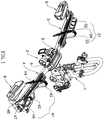
Fig. 2 is a perspective view to show the bicycle carry rack with the positioning member of the present invention; -
Fig. 2 is an exploded view of the front wheel support assembly of the present invention; -
Fig. 3 shows the positioning member, the second restricting unit and the second adjustment unit of the present invention; -
Fig. 4 shows that the positioning member of the present invention is pivotable, and -
Figs. 5 and 6 show that two bicycle front wheels of different sizes are positioned and secured by the present invention. - Referring to
Figs. 1 and2 , the positioning member of a bicycle carry rack of the present invention comprises abase 1 and asupport unit 2 which is connected to thebase 1. Thebase 1 is connected to a vehicle (not shown), and thesupport unit 2 comprises a rearwheel support assembly 3 and a frontwheel support assembly 4. The rearwheel support assembly 3 and the frontwheel support assembly 4 are connected to thebase 1 by aconnection unit 5. - The rear
wheel support assembly 3 comprises a rearwheel securing unit 31, and the rearwheel securing unit 31 includes arear wheel tray 32, a rearwheel restricting unit 33 and a rearwheel adjustment unit 34. The rearwheel restricting unit 33 is connected to therear wheel tray 32 which is used to support a bicycle rear wheel (not shown). The rearwheel restricting unit 33 extends through the bicycle rear wheel and is connected to the rearwheel adjustment unit 34 to secure the bicycle rear wheel to the rearwheel support assembly 3. - As shown in
Figs. 2 to 6 , the frontwheel support assembly 4 comprises a frontwheel securing unit 41, the frontwheel securing unit 41 having afront wheel tray 42, afirst restricting unit 43, afirst adjustment unit 44, apositioning member 45, asecond restricting unit 46 and asecond adjustment unit 47. Thefirst restricting unit 43 and thefirst adjustment unit 44 located at the first end of thefront wheel tray 42. Thefirst restricting unit 43 extends through a bicycle front wheel "W" and is connected to thefirst adjustment unit 44 so as to secure the bicycle front wheel "W". Thepositioning member 45 is located at the second end of thefront wheel tray 42 by anaxle 48 so that thepositioning member 45 is pivotable relative to the frontwheel support assembly 4 to prevent the bicycle front wheel "W" from sliding. Thesecond restricting unit 46 and thesecond adjustment unit 47 are connected to thepositioning member 45. Thesecond restricting unit 46 extends through the bicycle front wheel "W" and is connected to thesecond adjustment unit 47 so as to secure the bicycle front wheel "W". - In order to provide safety consideration, a
light unit 6 is located on outside of each of the rearwheel support assembly 3 and the frontwheel support assembly 4. - Each of the rear
wheel support assembly 3 and the frontwheel support assembly 4 is pviotable and foldable by theconnection unit 5 to save space. - As shown in
Figs. 1 to 4 , each of thefirst restricting unit 43 and thesecond restricting unit 46 include a teethed surface. Each of thefirst adjustment unit 44 and thesecond adjustment unit 47 include a spring pawl so as to be engaged with the teethed surface corresponding thereto. - As shown in
Fig. 3 , thepositioning member 45 includes arecess 451 which accommodates a portion of the bicycle front wheel "W" such that thepositioning member 45 is able to stop the bicycle front wheel "W". - The present invention is easily operated and used without extra explanation. When the bicycle is positioned on the
support unit 2, the rearwheel restricting unit 33 extends through the bicycle rear wheel and is connected to the rearwheel adjustment unit 34 which secures the rearwheel restricting unit 33 to secure the bicycle rear wheel to the rearwheel support assembly 3. - The
first restricting unit 43 extends through the bicycle front wheel "W" and is connected to thefirst adjustment unit 44 so as to initially secure the bicycle front wheel "W". The bicycle front wheel "W" is then engaged with therecess 451 of thepositioning member 45. Thesecond restricting unit 46 extends through the bicycle front wheel "W" and is connected to thesecond adjustment unit 47 so as to finally secure the bicycle front wheel "W". By this way, the bicycle is more secured. - While we have shown and described the embodiment in accordance with the present invention, it should be clear to those skilled in the art that further embodiments may be made without departing from the scope of the present invention.
Claims (5)
- A positioning member of a bicycle carry rack comprising:a base (1);a support unit (2) connected to the base (1) and comprising a rear wheel support assembly (3) and a front wheel support assembly (4), the rear wheel support assembly (3) and the front wheel support assembly (4) connected to the base (1) by a connection unit (5);the rear wheel support assembly (3) comprising a rear wheel securing unit (31), the rear wheel securing unit (31) having a rear wheel tray (32), a rear wheel restricting unit (33) and a rear wheel adjustment unit (34), the rear wheel restricting unit (33) connected to the rear wheel tray (32) which is adapted to support a bicycle rear wheel, the rear wheel restricting unit (33) adapted to extend through the bicycle rear wheel and being connected to the rear wheel adjustment unit (34), andthe front wheel support assembly (4) comprising a front wheel securing unit (41), the front wheel securing unit (41) having a front wheel tray (42), a first restricting unit (43), a first adjustment unit (44), a positioning member (45), a second restricting unit (46) and a second adjustment unit (47), the first restricting unit (43) and the first adjustment unit (44) located at a first end of the front wheel tray (42), the first restricting unit (43) adapted to extend through a bicycle front wheel "W" and being connected to the first adjustment unit (44), the positioning member (45) located at a second end of the front wheel tray (42) and pivotable relative to the front wheel support assembly (4), the positioning member (45) adapted to be engaged with the bicycle front wheel "W", the second restricting unit (46) and the second adjustment unit (47) connected to the positioning member (45), the second restricting unit (46) adapted to extend through the bicycle front wheel "W" and being connected to the second adjustment unit (47).
- The positioning member of a bicycle carry rack as claimed in claim 1, wherein each of the first restricting unit (43) and the second restricting unit (46) include a teethed surface, each of the first adjustment unit (44) and the second adjustment unit (47) include a spring pawl so as to be engaged with the teethed surface corresponding thereto.
- The positioning member of a bicycle carry rack as claimed in claim 1, wherein a light unit (6) is located on outside of each of the rear wheel support assembly and the front wheel support assembly (4).
- The positioning member of a bicycle carry rack as claimed in claim 1, wherein each of the rear wheel support assembly and the front wheel support assembly (4) is pviotable and foldable by the connection unit (5).
- The positioning member of a bicycle carry rack as claimed in claim 1, wherein the positioning member (45) includes a recess (451) which is adapted to accommodate a portion of the bicycle front wheel "W".
Applications Claiming Priority (1)
| Application Number | Priority Date | Filing Date | Title |
|---|---|---|---|
| TW108122514A TWI702161B (en) | 2019-06-27 | 2019-06-27 | Carrying frame bicycle front wheel fixing seat |
Publications (2)
| Publication Number | Publication Date |
|---|---|
| EP3756953A1 true EP3756953A1 (en) | 2020-12-30 |
| EP3756953B1 EP3756953B1 (en) | 2022-06-08 |
Family
ID=71069673
Family Applications (1)
| Application Number | Title | Priority Date | Filing Date |
|---|---|---|---|
| EP20178420.4A Active EP3756953B1 (en) | 2019-06-27 | 2020-06-05 | Bicycle carry rack with a front wheel positioning member |
Country Status (6)
| Country | Link |
|---|---|
| US (1) | US10967805B2 (en) |
| EP (1) | EP3756953B1 (en) |
| CN (1) | CN112141006A (en) |
| ES (1) | ES2926040T3 (en) |
| PL (1) | PL3756953T3 (en) |
| TW (1) | TWI702161B (en) |
Cited By (1)
| Publication number | Priority date | Publication date | Assignee | Title |
|---|---|---|---|---|
| US12409788B1 (en) * | 2024-03-05 | 2025-09-09 | King Rack Industrial Co., Ltd. | Bike rack |
Families Citing this family (12)
| Publication number | Priority date | Publication date | Assignee | Title |
|---|---|---|---|---|
| US10723278B2 (en) * | 2017-09-19 | 2020-07-28 | Kuat Innovations Llc | Trunk mounted rack |
| US11148607B1 (en) * | 2020-08-25 | 2021-10-19 | King Roof Industrial Co., Ltd. | Foldable positioning structure and bicycle carrier including the same |
| TWD214983S (en) * | 2020-09-30 | 2021-11-01 | 高鐵工業股份有限公司 | Carrying Frame (21) |
| USD1003215S1 (en) * | 2021-09-14 | 2023-10-31 | Ks International Group Co., Ltd. | Wheel support member for bicycle carrier |
| TWM631381U (en) * | 2022-02-25 | 2022-09-01 | 高鐵工業股份有限公司 | Quick release structure for bicycle-holding clamp arm of bicycle carrier |
| CN117246244A (en) | 2022-06-10 | 2023-12-19 | 杭州嘉迈机械有限公司 | Rear load carriers, clamping devices and systems |
| CN117246242A (en) * | 2022-06-10 | 2023-12-19 | 杭州嘉迈机械有限公司 | Wheel holder, extension module and rear load carrier |
| CN117246241A (en) | 2022-06-10 | 2023-12-19 | 杭州嘉迈机械有限公司 | suitcase |
| CN117246243A (en) | 2022-06-10 | 2023-12-19 | 杭州嘉迈机械有限公司 | Foldable bicycle bracket |
| USD1051018S1 (en) * | 2022-06-29 | 2024-11-12 | Ningbo Chenfan Auto Accessories Co., Ltd | Bike carrier |
| US12589698B2 (en) | 2023-04-21 | 2026-03-31 | Carman Enterprise Co., Ltd | Triple sliding |
| TWI882719B (en) * | 2024-03-07 | 2025-05-01 | 高鐵工業股份有限公司 | Carrying rack auxiliary rod folding stable structure |
Citations (3)
| Publication number | Priority date | Publication date | Assignee | Title |
|---|---|---|---|---|
| US20070164065A1 (en) * | 2005-08-09 | 2007-07-19 | Davis Brian F | Adjustable bicycle wheel retainer |
| US20080164292A1 (en) * | 2006-06-29 | 2008-07-10 | Michael Kent Farney | Bicycle carrier |
| EP3428016A1 (en) * | 2017-07-14 | 2019-01-16 | Thule Sweden AB | A vehicle mounted bicycle carrier |
Family Cites Families (16)
| Publication number | Priority date | Publication date | Assignee | Title |
|---|---|---|---|---|
| US4524893A (en) * | 1984-09-10 | 1985-06-25 | Yakima, Inc. | Bicycle carrier |
| US5509776A (en) * | 1993-07-22 | 1996-04-23 | Hs Technik Und Design Technische Entwicklungen Gmbh | Apparatus for raising and lowering a load on or from a support |
| US6092706A (en) * | 1999-07-15 | 2000-07-25 | Bogan; Joel B. | B.C. bicycle rack |
| TW201111201A (en) * | 2009-06-05 | 2011-04-01 | Yakima Products Inc | Upright bike mount |
| WO2012032771A1 (en) * | 2010-09-06 | 2012-03-15 | 株式会社カーメイト | Wheel retaining device for bicycle carrier |
| EP2703224B1 (en) * | 2012-08-28 | 2015-04-29 | Thule Sweden AB | Load carrier for a vehicle |
| CN202743148U (en) * | 2012-08-31 | 2013-02-20 | 高铁工业股份有限公司 | Adjustable bicycle wheel support seat for carrying frame |
| TWM452895U (en) * | 2013-01-09 | 2013-05-11 | King Rack Ind Co Ltd | Foldable bike carrier structure |
| CN206615161U (en) * | 2014-06-05 | 2017-11-07 | 北部瑞典公司 | Wheel holder and bike rack for the bike rack of vehicle |
| EP3188932B1 (en) * | 2014-09-05 | 2019-04-03 | Cequent Performance Products, Inc. | Bike carrier |
| CN204399012U (en) * | 2014-12-05 | 2015-06-17 | 高铁工业股份有限公司 | Front wheel supporting device with frame |
| TWM511970U (en) * | 2014-12-05 | 2015-11-11 | King Rack Ind Co Ltd | Front wheel support device for carrying a frame |
| US11130436B2 (en) * | 2017-12-23 | 2021-09-28 | Dma, Corp. | Vehicle hauling apparatus |
| US10183627B1 (en) * | 2018-01-03 | 2019-01-22 | Yao-Huang Liu | Bike carrier |
| CN208881704U (en) * | 2018-10-15 | 2019-05-21 | 高铁工业股份有限公司 | An improved structure of a belt for fixing a bicycle |
| TWM574987U (en) * | 2018-10-29 | 2019-03-01 | 高鐵工業股份有限公司 | Foldable structure of carrying frame |
-
2019
- 2019-06-27 TW TW108122514A patent/TWI702161B/en active
- 2019-07-05 CN CN201910604200.0A patent/CN112141006A/en active Pending
- 2019-12-11 US US16/711,360 patent/US10967805B2/en active Active
-
2020
- 2020-06-05 PL PL20178420.4T patent/PL3756953T3/en unknown
- 2020-06-05 EP EP20178420.4A patent/EP3756953B1/en active Active
- 2020-06-05 ES ES20178420T patent/ES2926040T3/en active Active
Patent Citations (3)
| Publication number | Priority date | Publication date | Assignee | Title |
|---|---|---|---|---|
| US20070164065A1 (en) * | 2005-08-09 | 2007-07-19 | Davis Brian F | Adjustable bicycle wheel retainer |
| US20080164292A1 (en) * | 2006-06-29 | 2008-07-10 | Michael Kent Farney | Bicycle carrier |
| EP3428016A1 (en) * | 2017-07-14 | 2019-01-16 | Thule Sweden AB | A vehicle mounted bicycle carrier |
Non-Patent Citations (1)
| Title |
|---|
| THULE SWEDEN: "Thule EasyFold XT Instructions", 2016, XP002800126, Retrieved from the Internet <URL:https://manuall.co.uk/thule-easyfold-xt-2-bicycle-carrier/> [retrieved on 20200825] * |
Cited By (1)
| Publication number | Priority date | Publication date | Assignee | Title |
|---|---|---|---|---|
| US12409788B1 (en) * | 2024-03-05 | 2025-09-09 | King Rack Industrial Co., Ltd. | Bike rack |
Also Published As
| Publication number | Publication date |
|---|---|
| US20200406829A1 (en) | 2020-12-31 |
| EP3756953B1 (en) | 2022-06-08 |
| US10967805B2 (en) | 2021-04-06 |
| TW202100385A (en) | 2021-01-01 |
| TWI702161B (en) | 2020-08-21 |
| CN112141006A (en) | 2020-12-29 |
| PL3756953T3 (en) | 2022-11-07 |
| ES2926040T3 (en) | 2022-10-21 |
Similar Documents
| Publication | Publication Date | Title |
|---|---|---|
| EP3756953A1 (en) | Bicycle carry rack with a front wheel positioning member | |
| US6378815B1 (en) | Mounting assembly for motor vehicles | |
| US10604204B2 (en) | Bicycle saddle bag | |
| US7000814B2 (en) | Securing device for bicycle rack on vehicle | |
| US6561400B2 (en) | Mounting assembly for motor vehicles | |
| US20120043286A1 (en) | Bicycle rack | |
| US20090230162A1 (en) | Foldable bicycle rack | |
| US20080000940A1 (en) | Bicycle rack connection to roof rack of vehicles | |
| TW201422476A (en) | Bicycle frame with integrated tool storage | |
| US7975888B2 (en) | Rear-mounted bicycle carrier with stabilizing structures | |
| US20240375600A1 (en) | Bumper with selectively attachable light bars | |
| JP2016078470A (en) | Cargo box mount bracket of vehicle | |
| US20080296330A1 (en) | Mountable storage arrangement | |
| US20060172831A1 (en) | Holding device for a rear derailleur of a bicycle | |
| US20130153736A1 (en) | Automotive side view mirror attachment structure | |
| JP7852138B2 (en) | Training wheel assembly and bicycle | |
| US8434655B2 (en) | Crown fork supported bicycle carrier | |
| EP1864857B1 (en) | Vehicular lamp to be mounted in a car body opening | |
| US20060060623A1 (en) | Bike carrying rack for automobile | |
| US20200122644A1 (en) | Mounting specification adjustable front fork mount | |
| US9604566B1 (en) | Lamp structure | |
| US20080029984A1 (en) | Metal grip for T-bar | |
| US11926289B2 (en) | Bicycle rack with assembly features | |
| US7543879B2 (en) | Windshield mounting system | |
| US20230020722A1 (en) | Vertical bicycle rack |
Legal Events
| Date | Code | Title | Description |
|---|---|---|---|
| PUAI | Public reference made under article 153(3) epc to a published international application that has entered the european phase |
Free format text: ORIGINAL CODE: 0009012 |
|
| STAA | Information on the status of an ep patent application or granted ep patent |
Free format text: STATUS: THE APPLICATION HAS BEEN PUBLISHED |
|
| AK | Designated contracting states |
Kind code of ref document: A1 Designated state(s): AL AT BE BG CH CY CZ DE DK EE ES FI FR GB GR HR HU IE IS IT LI LT LU LV MC MK MT NL NO PL PT RO RS SE SI SK SM TR |
|
| AX | Request for extension of the european patent |
Extension state: BA ME |
|
| STAA | Information on the status of an ep patent application or granted ep patent |
Free format text: STATUS: REQUEST FOR EXAMINATION WAS MADE |
|
| 17P | Request for examination filed |
Effective date: 20210629 |
|
| RBV | Designated contracting states (corrected) |
Designated state(s): AL AT BE BG CH CY CZ DE DK EE ES FI FR GB GR HR HU IE IS IT LI LT LU LV MC MK MT NL NO PL PT RO RS SE SI SK SM TR |
|
| GRAP | Despatch of communication of intention to grant a patent |
Free format text: ORIGINAL CODE: EPIDOSNIGR1 |
|
| RIC1 | Information provided on ipc code assigned before grant |
Ipc: B60R 9/06 20060101ALI20211105BHEP Ipc: B60R 9/10 20060101AFI20211105BHEP |
|
| STAA | Information on the status of an ep patent application or granted ep patent |
Free format text: STATUS: GRANT OF PATENT IS INTENDED |
|
| INTG | Intention to grant announced |
Effective date: 20211216 |
|
| RAP3 | Party data changed (applicant data changed or rights of an application transferred) |
Owner name: KING RACK INDUSTRIAL CO., LTD. |
|
| GRAS | Grant fee paid |
Free format text: ORIGINAL CODE: EPIDOSNIGR3 |
|
| GRAA | (expected) grant |
Free format text: ORIGINAL CODE: 0009210 |
|
| STAA | Information on the status of an ep patent application or granted ep patent |
Free format text: STATUS: THE PATENT HAS BEEN GRANTED |
|
| AK | Designated contracting states |
Kind code of ref document: B1 Designated state(s): AL AT BE BG CH CY CZ DE DK EE ES FI FR GB GR HR HU IE IS IT LI LT LU LV MC MK MT NL NO PL PT RO RS SE SI SK SM TR |
|
| REG | Reference to a national code |
Ref country code: AT Ref legal event code: REF Ref document number: 1496724 Country of ref document: AT Kind code of ref document: T Effective date: 20220615 Ref country code: CH Ref legal event code: EP |
|
| REG | Reference to a national code |
Ref country code: DE Ref legal event code: R096 Ref document number: 602020003441 Country of ref document: DE |
|
| REG | Reference to a national code |
Ref country code: IE Ref legal event code: FG4D |
|
| REG | Reference to a national code |
Ref country code: NL Ref legal event code: FP |
|
| REG | Reference to a national code |
Ref country code: LT Ref legal event code: MG9D |
|
| REG | Reference to a national code |
Ref country code: ES Ref legal event code: FG2A Ref document number: 2926040 Country of ref document: ES Kind code of ref document: T3 Effective date: 20221021 |
|
| PG25 | Lapsed in a contracting state [announced via postgrant information from national office to epo] |
Ref country code: SE Free format text: LAPSE BECAUSE OF FAILURE TO SUBMIT A TRANSLATION OF THE DESCRIPTION OR TO PAY THE FEE WITHIN THE PRESCRIBED TIME-LIMIT Effective date: 20220608 Ref country code: NO Free format text: LAPSE BECAUSE OF FAILURE TO SUBMIT A TRANSLATION OF THE DESCRIPTION OR TO PAY THE FEE WITHIN THE PRESCRIBED TIME-LIMIT Effective date: 20220908 Ref country code: LT Free format text: LAPSE BECAUSE OF FAILURE TO SUBMIT A TRANSLATION OF THE DESCRIPTION OR TO PAY THE FEE WITHIN THE PRESCRIBED TIME-LIMIT Effective date: 20220608 Ref country code: HR Free format text: LAPSE BECAUSE OF FAILURE TO SUBMIT A TRANSLATION OF THE DESCRIPTION OR TO PAY THE FEE WITHIN THE PRESCRIBED TIME-LIMIT Effective date: 20220608 Ref country code: GR Free format text: LAPSE BECAUSE OF FAILURE TO SUBMIT A TRANSLATION OF THE DESCRIPTION OR TO PAY THE FEE WITHIN THE PRESCRIBED TIME-LIMIT Effective date: 20220909 Ref country code: FI Free format text: LAPSE BECAUSE OF FAILURE TO SUBMIT A TRANSLATION OF THE DESCRIPTION OR TO PAY THE FEE WITHIN THE PRESCRIBED TIME-LIMIT Effective date: 20220608 Ref country code: BG Free format text: LAPSE BECAUSE OF FAILURE TO SUBMIT A TRANSLATION OF THE DESCRIPTION OR TO PAY THE FEE WITHIN THE PRESCRIBED TIME-LIMIT Effective date: 20220908 |
|
| REG | Reference to a national code |
Ref country code: AT Ref legal event code: MK05 Ref document number: 1496724 Country of ref document: AT Kind code of ref document: T Effective date: 20220608 |
|
| PG25 | Lapsed in a contracting state [announced via postgrant information from national office to epo] |
Ref country code: RS Free format text: LAPSE BECAUSE OF FAILURE TO SUBMIT A TRANSLATION OF THE DESCRIPTION OR TO PAY THE FEE WITHIN THE PRESCRIBED TIME-LIMIT Effective date: 20220608 Ref country code: LV Free format text: LAPSE BECAUSE OF FAILURE TO SUBMIT A TRANSLATION OF THE DESCRIPTION OR TO PAY THE FEE WITHIN THE PRESCRIBED TIME-LIMIT Effective date: 20220608 |
|
| PG25 | Lapsed in a contracting state [announced via postgrant information from national office to epo] |
Ref country code: SM Free format text: LAPSE BECAUSE OF FAILURE TO SUBMIT A TRANSLATION OF THE DESCRIPTION OR TO PAY THE FEE WITHIN THE PRESCRIBED TIME-LIMIT Effective date: 20220608 Ref country code: RO Free format text: LAPSE BECAUSE OF FAILURE TO SUBMIT A TRANSLATION OF THE DESCRIPTION OR TO PAY THE FEE WITHIN THE PRESCRIBED TIME-LIMIT Effective date: 20220608 Ref country code: PT Free format text: LAPSE BECAUSE OF FAILURE TO SUBMIT A TRANSLATION OF THE DESCRIPTION OR TO PAY THE FEE WITHIN THE PRESCRIBED TIME-LIMIT Effective date: 20221010 Ref country code: EE Free format text: LAPSE BECAUSE OF FAILURE TO SUBMIT A TRANSLATION OF THE DESCRIPTION OR TO PAY THE FEE WITHIN THE PRESCRIBED TIME-LIMIT Effective date: 20220608 Ref country code: AT Free format text: LAPSE BECAUSE OF FAILURE TO SUBMIT A TRANSLATION OF THE DESCRIPTION OR TO PAY THE FEE WITHIN THE PRESCRIBED TIME-LIMIT Effective date: 20220608 |
|
| PG25 | Lapsed in a contracting state [announced via postgrant information from national office to epo] |
Ref country code: IS Free format text: LAPSE BECAUSE OF FAILURE TO SUBMIT A TRANSLATION OF THE DESCRIPTION OR TO PAY THE FEE WITHIN THE PRESCRIBED TIME-LIMIT Effective date: 20221008 |
|
| REG | Reference to a national code |
Ref country code: DE Ref legal event code: R097 Ref document number: 602020003441 Country of ref document: DE |
|
| PG25 | Lapsed in a contracting state [announced via postgrant information from national office to epo] |
Ref country code: AL Free format text: LAPSE BECAUSE OF FAILURE TO SUBMIT A TRANSLATION OF THE DESCRIPTION OR TO PAY THE FEE WITHIN THE PRESCRIBED TIME-LIMIT Effective date: 20220608 |
|
| PLBE | No opposition filed within time limit |
Free format text: ORIGINAL CODE: 0009261 |
|
| STAA | Information on the status of an ep patent application or granted ep patent |
Free format text: STATUS: NO OPPOSITION FILED WITHIN TIME LIMIT |
|
| PG25 | Lapsed in a contracting state [announced via postgrant information from national office to epo] |
Ref country code: DK Free format text: LAPSE BECAUSE OF FAILURE TO SUBMIT A TRANSLATION OF THE DESCRIPTION OR TO PAY THE FEE WITHIN THE PRESCRIBED TIME-LIMIT Effective date: 20220608 |
|
| 26N | No opposition filed |
Effective date: 20230310 |
|
| PG25 | Lapsed in a contracting state [announced via postgrant information from national office to epo] |
Ref country code: SI Free format text: LAPSE BECAUSE OF FAILURE TO SUBMIT A TRANSLATION OF THE DESCRIPTION OR TO PAY THE FEE WITHIN THE PRESCRIBED TIME-LIMIT Effective date: 20220608 |
|
| PG25 | Lapsed in a contracting state [announced via postgrant information from national office to epo] |
Ref country code: MC Free format text: LAPSE BECAUSE OF FAILURE TO SUBMIT A TRANSLATION OF THE DESCRIPTION OR TO PAY THE FEE WITHIN THE PRESCRIBED TIME-LIMIT Effective date: 20220608 |
|
| PG25 | Lapsed in a contracting state [announced via postgrant information from national office to epo] |
Ref country code: MC Free format text: LAPSE BECAUSE OF FAILURE TO SUBMIT A TRANSLATION OF THE DESCRIPTION OR TO PAY THE FEE WITHIN THE PRESCRIBED TIME-LIMIT Effective date: 20220608 Ref country code: IT Free format text: LAPSE BECAUSE OF FAILURE TO SUBMIT A TRANSLATION OF THE DESCRIPTION OR TO PAY THE FEE WITHIN THE PRESCRIBED TIME-LIMIT Effective date: 20220608 Ref country code: CZ Free format text: LAPSE BECAUSE OF NON-PAYMENT OF DUE FEES Effective date: 20230605 |
|
| REG | Reference to a national code |
Ref country code: CH Ref legal event code: PL |
|
| REG | Reference to a national code |
Ref country code: BE Ref legal event code: MM Effective date: 20230630 |
|
| PG25 | Lapsed in a contracting state [announced via postgrant information from national office to epo] |
Ref country code: LU Free format text: LAPSE BECAUSE OF NON-PAYMENT OF DUE FEES Effective date: 20230605 |
|
| REG | Reference to a national code |
Ref country code: IE Ref legal event code: MM4A |
|
| PG25 | Lapsed in a contracting state [announced via postgrant information from national office to epo] |
Ref country code: LU Free format text: LAPSE BECAUSE OF NON-PAYMENT OF DUE FEES Effective date: 20230605 |
|
| REG | Reference to a national code |
Ref country code: SK Ref legal event code: MM4A Ref document number: E 40270 Country of ref document: SK Effective date: 20230605 |
|
| PG25 | Lapsed in a contracting state [announced via postgrant information from national office to epo] |
Ref country code: IE Free format text: LAPSE BECAUSE OF NON-PAYMENT OF DUE FEES Effective date: 20230605 |
|
| PG25 | Lapsed in a contracting state [announced via postgrant information from national office to epo] |
Ref country code: IE Free format text: LAPSE BECAUSE OF NON-PAYMENT OF DUE FEES Effective date: 20230605 Ref country code: CH Free format text: LAPSE BECAUSE OF NON-PAYMENT OF DUE FEES Effective date: 20230630 Ref country code: SK Free format text: LAPSE BECAUSE OF NON-PAYMENT OF DUE FEES Effective date: 20230605 |
|
| PG25 | Lapsed in a contracting state [announced via postgrant information from national office to epo] |
Ref country code: BE Free format text: LAPSE BECAUSE OF NON-PAYMENT OF DUE FEES Effective date: 20230630 |
|
| REG | Reference to a national code |
Ref country code: ES Ref legal event code: FD2A Effective date: 20240729 |
|
| PGFP | Annual fee paid to national office [announced via postgrant information from national office to epo] |
Ref country code: PL Payment date: 20240523 Year of fee payment: 5 |
|
| PG25 | Lapsed in a contracting state [announced via postgrant information from national office to epo] |
Ref country code: ES Free format text: LAPSE BECAUSE OF NON-PAYMENT OF DUE FEES Effective date: 20230606 |
|
| PG25 | Lapsed in a contracting state [announced via postgrant information from national office to epo] |
Ref country code: ES Free format text: LAPSE BECAUSE OF NON-PAYMENT OF DUE FEES Effective date: 20230606 |
|
| PG25 | Lapsed in a contracting state [announced via postgrant information from national office to epo] |
Ref country code: BG Free format text: LAPSE BECAUSE OF FAILURE TO SUBMIT A TRANSLATION OF THE DESCRIPTION OR TO PAY THE FEE WITHIN THE PRESCRIBED TIME-LIMIT Effective date: 20220608 |
|
| PG25 | Lapsed in a contracting state [announced via postgrant information from national office to epo] |
Ref country code: BG Free format text: LAPSE BECAUSE OF FAILURE TO SUBMIT A TRANSLATION OF THE DESCRIPTION OR TO PAY THE FEE WITHIN THE PRESCRIBED TIME-LIMIT Effective date: 20220608 |
|
| PGFP | Annual fee paid to national office [announced via postgrant information from national office to epo] |
Ref country code: NL Payment date: 20250514 Year of fee payment: 6 |
|
| PGFP | Annual fee paid to national office [announced via postgrant information from national office to epo] |
Ref country code: DE Payment date: 20250415 Year of fee payment: 6 |
|
| PGFP | Annual fee paid to national office [announced via postgrant information from national office to epo] |
Ref country code: GB Payment date: 20250514 Year of fee payment: 6 |
|
| PGFP | Annual fee paid to national office [announced via postgrant information from national office to epo] |
Ref country code: FR Payment date: 20250514 Year of fee payment: 6 |
|
| PG25 | Lapsed in a contracting state [announced via postgrant information from national office to epo] |
Ref country code: CY Free format text: LAPSE BECAUSE OF FAILURE TO SUBMIT A TRANSLATION OF THE DESCRIPTION OR TO PAY THE FEE WITHIN THE PRESCRIBED TIME-LIMIT; INVALID AB INITIO Effective date: 20200605 |
|
| PG25 | Lapsed in a contracting state [announced via postgrant information from national office to epo] |
Ref country code: HU Free format text: LAPSE BECAUSE OF FAILURE TO SUBMIT A TRANSLATION OF THE DESCRIPTION OR TO PAY THE FEE WITHIN THE PRESCRIBED TIME-LIMIT; INVALID AB INITIO Effective date: 20200605 |
|
| PG25 | Lapsed in a contracting state [announced via postgrant information from national office to epo] |
Ref country code: TR Free format text: LAPSE BECAUSE OF FAILURE TO SUBMIT A TRANSLATION OF THE DESCRIPTION OR TO PAY THE FEE WITHIN THE PRESCRIBED TIME-LIMIT Effective date: 20220608 |