EP3756898A1 - Inkjet printing apparatus and inkjet printing method - Google Patents
Inkjet printing apparatus and inkjet printing method Download PDFInfo
- Publication number
- EP3756898A1 EP3756898A1 EP20182301.0A EP20182301A EP3756898A1 EP 3756898 A1 EP3756898 A1 EP 3756898A1 EP 20182301 A EP20182301 A EP 20182301A EP 3756898 A1 EP3756898 A1 EP 3756898A1
- Authority
- EP
- European Patent Office
- Prior art keywords
- process chamber
- recording medium
- inlet
- outlet
- inkjet printing
- Prior art date
- Legal status (The legal status is an assumption and is not a legal conclusion. Google has not performed a legal analysis and makes no representation as to the accuracy of the status listed.)
- Granted
Links
Images




Classifications
-
- B—PERFORMING OPERATIONS; TRANSPORTING
- B41—PRINTING; LINING MACHINES; TYPEWRITERS; STAMPS
- B41J—TYPEWRITERS; SELECTIVE PRINTING MECHANISMS, i.e. MECHANISMS PRINTING OTHERWISE THAN FROM A FORME; CORRECTION OF TYPOGRAPHICAL ERRORS
- B41J11/00—Devices or arrangements of selective printing mechanisms, e.g. ink-jet printers or thermal printers, for supporting or handling copy material in sheet or web form
- B41J11/0015—Devices or arrangements of selective printing mechanisms, e.g. ink-jet printers or thermal printers, for supporting or handling copy material in sheet or web form for treating before, during or after printing or for uniform coating or laminating the copy material before or after printing
- B41J11/002—Curing or drying the ink on the copy materials, e.g. by heating or irradiating
- B41J11/0021—Curing or drying the ink on the copy materials, e.g. by heating or irradiating using irradiation
- B41J11/00214—Curing or drying the ink on the copy materials, e.g. by heating or irradiating using irradiation using UV radiation
-
- B—PERFORMING OPERATIONS; TRANSPORTING
- B41—PRINTING; LINING MACHINES; TYPEWRITERS; STAMPS
- B41J—TYPEWRITERS; SELECTIVE PRINTING MECHANISMS, i.e. MECHANISMS PRINTING OTHERWISE THAN FROM A FORME; CORRECTION OF TYPOGRAPHICAL ERRORS
- B41J29/00—Details of, or accessories for, typewriters or selective printing mechanisms not otherwise provided for
- B41J29/377—Cooling or ventilating arrangements
-
- B—PERFORMING OPERATIONS; TRANSPORTING
- B41—PRINTING; LINING MACHINES; TYPEWRITERS; STAMPS
- B41J—TYPEWRITERS; SELECTIVE PRINTING MECHANISMS, i.e. MECHANISMS PRINTING OTHERWISE THAN FROM A FORME; CORRECTION OF TYPOGRAPHICAL ERRORS
- B41J29/00—Details of, or accessories for, typewriters or selective printing mechanisms not otherwise provided for
- B41J29/38—Drives, motors, controls or automatic cut-off devices for the entire printing mechanism
Definitions
- the present invention relates to a technique of making a print on a recording surface of a recording medium on the basis of an inkjet system.
- Japanese Patent Application Laid-Open No. 2012-166539 discloses an active energy ray irradiation apparatus including: a boundary layer stripping part with a gas suction port for stripping off a gas boundary layer in the vicinity of a surface of a medium given an active energy ray curing type material; an inert gas supplier that supplies an inert gas to the surface of the medium after stripping of the gas boundary layer; a layer flow securing section that secures a layer flow of the inert gas on the surface of the medium; and an energy ray irradiator that emits an active energy ray toward the material applied surface of the medium through the layer flow of the inert gas.
- Japanese Patent Application Laid-Open No. 2012-166539 says that supplying the inert gas after stripping of the gas boundary layer on the medium allows reduction in oxygen concentration locally on the medium, and this results in efficient curing
- An object of the present invention is to provide a technique of alleviating reduction in printing quality in a case of supplying an inert gas during implementation of inkjet printing.
- a first aspect is intended for an inkjet printing apparatus that records an image by ejecting electromagnetic curing type ink to a recording medium.
- the inkjet printing apparatus includes a transport mechanism, an ejection head, a process chamber, an irradiator, an inert gas supplier, a casing, and an air discharge part.
- the transport mechanism transports a recording medium along a prescribed transport path.
- the ejection head ejects the ink to the recording medium.
- the process chamber arranged downstream from the ejection head and having an inlet and an outlet for passing the recording medium through the process chamber.
- the irradiator irradiates the recording medium in the process chamber with an electromagnetic wave.
- the inert gas supplier supplies an inert gas into the process chamber.
- the casing accommodates the ejection head and the process chamber.
- the air discharge part has an inlet-side suction port, an outlet-side suction port and an exhaust pipe.
- the inlet-side suction port is provided upstream from the inlet of the process chamber.
- the outlet-side suction port is provided downstream from the outlet of the process chamber.
- the exhaust pipe guides atmosphere sucked through the inlet-side suction port and the outlet-side suction port to the outside of the casing.
- the inkjet printing apparatus further includes an inlet-side partition wall connected to the inlet of the process chamber and having a portion facing the transport path.
- the inlet-side suction port is opened at a part of the inlet-side partition wall toward the recording medium.
- pressure loss in the process chamber is greater than pressure loss in first suction space surrounded by the inlet-side partition wall.
- the inkjet printing apparatus according to any one of the first to third aspects further includes an outlet-side partition wall connected to the outlet of the process chamber and having a portion facing the transport path.
- the outlet-side suction port is opened at a part of the outlet-side partition wall toward the transport path.
- pressure loss in the process chamber is greater than pressure loss in space surrounded by the outlet-side partition wall.
- the inkjet printing apparatus according to any one of the first to fifth aspects further includes a roller having a cylindrical outer peripheral surface on which the recording medium is wound.
- the inert gas supplier supplies the inert gas toward the roller.
- At least one of the inlet-side suction port and the outlet-side suction port faces the outer peripheral surface of the roller.
- the air discharge part discharges the atmosphere per unit time of a larger amount than the amount of supply of the inert gas per unit time by the inert gas supplier.
- the inkjet printing apparatus according to any one of the first to ninth aspects further includes an oximeter that measures an oxygen concentration in the process chamber.
- the inkjet printing apparatus further includes a controller that controls the amount of discharge of the atmosphere by the air discharge part in response to output from the oximeter.
- a twelfth aspect is intended for an inkjet printing method of recording an image by ejecting electromagnetic curing type ink to a recording medium.
- the method includes (a) transporting a recording medium along a prescribed transport path, (b) ejecting the ink to the recording medium from an ejection head, (c) introducing the recording medium into a process chamber arranged downstream from the ejection head through an inlet of the process chamber, (d) irradiating the recording medium in the process chamber with an electromagnetic wave, (e) supplying an inert gas into the process chamber, (f) taking the recording medium out of the process chamber through an outlet of the process chamber and (g) sucking atmosphere through each of an inlet-side suction port provided upstream from the inlet of the process chamber and an outlet-side suction port provided downstream from the outlet of the process chamber, and discharging the sucked atmosphere to the outside of a casing accommodating the ejection head and the process chamber.
- the inkjet printing apparatus allows the inert gas flowing out through the inlet and the outlet of the process chamber to be discharged through the inlet-side suction port and the outlet-side suction port to the outside of the casing. This suppresses change in characteristics of the ink adhering to the recording medium to be caused by the move of the inert gas flowing out from the process chamber toward the ejection head and its vicinity upstream from the process chamber. In this way, reduction in printing quality is alleviated.
- the inkjet printing apparatus allows the atmosphere in the inlet-side partition wall connected to the inlet of the process chamber to be sucked through the inlet-side suction port. This allows the inert gas flowing out through the inlet to be discharged effectively to the outside of the casing.
- making pressure loss in the process chamber greater than pressure loss in the first suction space makes it difficult for the inert gas in the process chamber to flow out.
- the concentration of the inert gas in the process chamber is increased easily.
- a flow of the atmosphere into the space in the inlet-side partition wall is generated easily to achieve suction of the atmosphere favorably at the inlet-side suction port. This allows the inert gas flowing out from the process chamber to be sucked favorably.
- the inkjet printing apparatus allows the atmosphere in the outlet-side partition wall connected to the outlet of the process chamber to be sucked through the outlet-side suction port. This allows the inert gas flowing out through the outlet to be discharged effectively to the outside of the casing.
- increasing pressure loss in the process chamber makes it difficult for the inert gas in the process chamber to flow out.
- This makes the concentration of the inert gas in the process chamber easier to increase.
- a flow of the atmosphere into the space in the outlet-side partition wall is generated easily to achieve suction of the atmosphere favorably at the outlet-side suction port. This allows the inert gas leaking from inside the process chamber to be sucked favorably.
- the inkjet printing apparatus allows application of tension on the recording medium with the roller. Further, the inert gas is discharged onto the recording medium wound on the roller. Thus, the atmosphere on the recording medium is effectively replaced by the inert gas.
- the inkjet printing apparatus allows the inert gas exiting the outlet or the inlet of the process chamber and flowing over the roller to be sucked favorably.
- the inkjet printing apparatus allows the recording medium on the roller to be cooled effectively.
- the inkjet printing apparatus allows the air discharge part to discharge the atmosphere of a larger amount than the amount of supply of the inert gas to be supplied to the process chamber. This effectively suppresses the movement of the inert gas flowing out from the process chamber toward the ejection head and its vicinity.
- provision of the oximeter realizes detection of an oxygen concentration in the process chamber.
- the inkjet printing method allows the inert gas flowing out through the inlet and the outlet of the process chamber to be discharged through the inlet-side suction port and the outlet-side suction port to the outside of the casing. This suppresses change in characteristics of the ink adhering to the recording medium to be caused by the move of the inert gas flowing out from the process chamber toward the ejection head and its vicinity upstream from the process chamber. In this way, reduction in printing quality is suppressed.
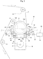
- Fig. 1 schematically shows the configuration of an inkjet printing apparatus 1 according to the preferred embodiment.
- the inkjet printing apparatus 1 records an image on a recording surface of a strip-shaped recording medium 9 (printing paper, for example) by ejecting droplets of ink from a plurality of ejection heads 21 while transporting the recording medium 9.
- a strip-shaped recording medium 9 printing paper, for example
- Ultraviolet curable ink to be cured by irradiation with an ultraviolet ray as an electromagnetic wave is applicable to the ink used in the inkjet printing apparatus 1.
- This ink can contain a curing initiator as a component for facilitating curing, for example.
- the inkjet printing apparatus 1 includes a transport mechanism 10, an image recording section 20, a support unit 30, a process chamber 40, an inert gas supplier 50, an air discharge part 60, an irradiator 70, and a controller 80. All the parts (including the image recording section 20 and the process chamber 40) except the controller 80 are accommodated in a box-shaped casing 90.
- the transport mechanism 10 is a mechanism for transporting the recording medium 9 in a moving direction conforming to a longitudinal direction of the recording medium 9.
- the transport mechanism 10 includes an unwinding section 11, a plurality of transport rollers 12, a chill roller 13, and a winding section 14.
- the transport rollers 12 include a direction switching roller 121 and a nip roller 122 described later.
- the recording medium 9 is unwound from the unwinding section 11 and transported along a transport path composed of the transport rollers 12.
- Each of the transport rollers 12 rotates about a horizontal axis to guide the recording medium 9 downstream of the moving direction.
- the recording medium 9 is collected on the winding section 14. In this way, the recording medium 9 is supported by the transport rollers 12, the chill roller 13 and others arranged at prescribed positions to be transported along a prescribed transport path TR1.
- the cleaner 15 includes a plurality of suction rollers 151 arranged proximately vertically.
- the suction rollers 151 rotate while contacting a recording surface 9a and a rear surface 9b of the recording medium 9. Foreign matters adhering to the recording surface 9a and the rear surface 9b of the recording medium 9 are adsorbed on the suction rollers 151 and removed. By doing so, the number of foreign matters adhering to the recording medium 9 before printing is reduced. This reduces the occurrence of printing failure such as rejection or exuding of ink due to foreign matters.
- the cleaner 15 may be equipped with another system (such as a suction mechanism) other than the suction rollers 151.
- the recording medium 9 moves under the image recording section 20 substantially horizontally in a direction in which the ejection heads 21 are aligned. During the move, the recording surface 9a of the recording medium 9 is pointed upward (toward the ejection heads 21).
- the transport mechanism 10 includes the direction switching roller 121, the chill roller 13, and the nip roller 122 arranged downstream of the moving direction from the image recording section 20.
- the nip roller 122 rotates actively at a constant speed while contacting the recording surface 9a and the rear surface 9b of the recording medium 9 and grasping the recording medium 9.
- the transport mechanism 10 adjusts the rotation speed of the unwinding section 11 relative to the rotation speed of the nip roller 122. This applies tension to the recording medium 9. As a result, sags or creases of the recording medium 9 are reduced during the transport.
- the image recording section 20 is a mechanism that ejects ultraviolet curing type ink to the recording medium 9 transported by the transport mechanism 10.
- the image recording section 20 of the preferred embodiment includes four ejection heads 21.
- the four ejection heads 21 are aligned in the moving direction of the recording medium 9.
- droplets of ink of each color of C (cyan), M (magenta), Y (yellow), an K (black) are ejected from the four ejection heads 21 respectively toward the recording surface 9a of the recording medium 9.
- the droplets of each color ink become color components of a color image. By doing so, the color image is formed on the recording surface 9a of the recording medium 9.
- a step of ejecting the ink from the ejection head 21 to the recording medium 9 is an example of an ink ejection step.
- the support unit 30 includes a plurality of support tables 31 aligned in the moving direction of the recording medium 9.
- the four ejection heads 21 are each attached to one of these support tables 31. In this way, the four ejection heads 21 are supported and the positions of these heads relative to each other are fixed.
- Each of the support tables 31 has a through hole 311 formed at the center of the support table 31 A lower end of the ejection head 21 is inserted into the through hole 311. In this way, the lower surface of the ejection head 21 attached to the support table 31 is caused to face the recording surface 9a of the recording medium 9 without being blocked by the support table 31.
- Fig. 2 is a vertical sectional view of the ejection head 21 and the support table 31.
- the lower surface of each ejection head 21 is provided with a plurality of nozzles 211 for ejecting droplets of ink.
- the nozzles 211 are aligned regularly in the width direction of the recording medium 9 perpendicular to the moving direction of the recording medium 9 in such a manner as to cover the width of the recording medium 9 substantially entirely.
- the ejection head 21 is fixed to the support table 31 while the lower end of the ejection head 21 is fitted in the through hole 311 of the support table 31.
- the lower surface of the ejection head 21 is a nozzle surface 212 where the nozzles 211 are formed.
- the direction switching roller 121 as a switcher is arranged downstream as viewed from the image recording section 20.
- the direction switching roller 121 rotates about a horizontal axis extending in the width direction while contacting the rear surface 9b of the recording medium 9. This bends the recording medium 9 to a direction opposing the recording surface 9a.
- the moving direction of the recording medium 9 is switched from a first direction (in the preferred embodiment, a substantially horizontal direction) to a second direction (in the preferred embodiment, a vertically downward direction).
- the direction switching roller 121 contacts the rear surface 9b of the recording medium 9.
- the surface of the direction switching roller 121 is prevented from contacting ink in an uncured state. This suppresses reduction in the quality of an image on the recording medium 9 to be caused by the contact with the direction switching roller 121.
- a member for switching the moving direction of the recording medium 9 is absent on a side of the recording surface 9a of the recording medium 9.
- Fig. 3 is a schematic side view showing a configuration including the irradiator 70 and its vicinity of the inkjet printing apparatus 1.
- Fig. 4 is a schematic front view showing a configuration including the irradiator 70 and its vicinity of the inkjet printing apparatus 1.
- the chill roller 13 rotates about a horizontal axis 131 extending in the width direction while contacting the rear surface 9b of the recording medium 9.
- the horizontal axis 131 has one end connected to a motor 13M. Driving of the motor 13M rotates the horizontal axis 131, thereby rotating the chill roller 13.
- One side-wall 133 is provided at each of opposite sides of the chill roller 13 in the width direction in such a manner that the side-walls 133 face each other.
- the horizontal axis 131 is rotatably supported by the two side-walls 133.
- the chill roller 13 is arranged substantially vertically above the process chamber 40 and the irradiator 70.
- the chill roller 13 has an outer peripheral surface 13S. The diameter of the outer peripheral surface 13S is greater than the diameter of an outer peripheral surface of the transport rollers 12.
- Coolant 130 is stored inside the chill roller 13.
- the Coolant 130 is circulated appropriately by a circulator not shown in the drawings. By doing so, the surface of the chill roller 13 is cooled to be maintained at a certain temperature.
- the structure and the mechanism for storing and circulating the coolant 130 is a example of a cooling mechanism of cooling the outer peripheral surface 13S of the chill roller 13.
- the process chamber 40 is arranged downstream from the ejection head 21. In other words, the process chamber 40 is arranged downstream from a position at which ink from the ejection head 21 adheres to the recording medium 9.
- the process chamber 40 has an inlet 41 and an outlet 42 for passing the recording medium 9 through the process chamber 40.
- the inlet 41 is an opening for introducing the recording medium 9 into process space 40R inside the process chamber 40.
- the outlet 42 is an opening for taking the recording medium 9 out of the process space 40R.
- the process chamber 40 includes a first wall 43, a second wall 44, and a third wall 45.
- the first wall 43 forms an upstream side surface of the process space 40R.
- the second wall 44 forms a downstream side surface of the process space 40R.
- the third wall 45 is a plate-like member connecting the first wall 43 and the second wall 44 and forming the bottom surface of the process space 40R. Both ends of the first wall 43, the second wall 44, and the third wall 45 in the width direction are respectively connected to corresponding one of the side-walls 133. Namely, the respective inward surfaces of the two side-walls 133 form the side surfaces of the process space 40R on the opposite sides in the width direction.
- the first wall 43 has a first facing surface 43S facing the outer peripheral surface 13S of the chill roller 13 and curved along the outer peripheral surface 13S.
- the first facing surface 43S and the outer peripheral surface 13S form a first flow path 46a.
- the first flow path 46a has an upstream end functioning as the inlet 41.
- the second wall 44 has a second facing surface 44S facing the outer peripheral surface 13S of the chill roller 13 and curved along the outer peripheral surface 13S.
- the second facing surface 44S and the outer peripheral surface 13S form a second flow path 46b.
- the second flow path 46b has a downstream end functioning as the outlet 42.
- the chill roller 13 is arranged on a top side opposite the third wall 45 in the process chamber 40. Namely, the outer peripheral surface 13S of the chill roller 13 (more specifically, a part of the outer peripheral surface 13S caught between the first wall 43 and the second wall 44) forms the top surface of the process chamber 40. In this way, the process chamber 40 is configured as substantially closed space except the inlet 41 and the outlet 42.
- the side surfaces of the process chamber 40 on the opposite sides of the width direction are not always required to be configured using the two side-walls 133.
- a side-wall standing from the third wall 45 toward the chill roller 13 and extending in the moving direction may be provided on each of opposite external sides of the transport path TR1 in the width direction.
- An oximeter 47 is provided to the process space 40R.
- the oximeter 47 measures an oxygen concentration in the process space 40R, and outputs the measured oxygen concentration to the controller 80.
- Measuring an oxygen concentration in the process space 40R using the oximeter 47 is not an absolute necessity.
- a mechanism of feeding out atmosphere from inside the process space 40R to the outside through a predetermined hole may be provided, and an oximeter may be provided on a path of the outgoing atmosphere. In this case, an oxygen concentration in the process chamber 40 can be measured by measuring an oxygen concentration in this atmosphere.
- a step performed by the transport mechanism 10 of introducing the recording medium 9 into the process chamber 40 through the inlet 41 is an example of an incoming step.
- a step performed by the transport mechanism 10 of taking the recording medium 9 out of the process chamber 40 through the outlet 42 is an example of an outgoing step.
- the inert gas supplier 50 supplies an inert gas into the process chamber 40. More specifically, the inert gas supplier 50 supplies nitrogen gas as the inert gas toward the recording surface 9a of the recording medium 9 in the process chamber 40. As shown in Fig. 3 , the inert gas supplier 50 has a supply port 51 for supplying nitrogen gas toward the recording surface 9a of the recording medium 9. A supply source 54 of nitrogen gas is connected to the supply port 51 through a pipe 52 and an open/close valve 53. Opening the open/close valve 53 feeds nitrogen gas from the supply source 54 toward the supply port 51. Adjusting a degree of opening of the open/close valve 53 allows adjustment of the pressure of nitrogen gas supplied through the supply port 51.
- the pressure of nitrogen gas supplied through the supply port 51 may be adjusted by a pressure adjusting mechanism provided separately from the open/close valve 53. To realize supply of nitrogen gas of a higher pressure, the supply port 51 may be provided with an additional ejection mechanism such as what is called an air knife.
- a step implemented by the inert gas supplier 50 of supplying the inert gas into the process chamber 40 is an example of an inert gas supply step.
- a tip portion of the pipe 52 is provided inside the first wall 43 and the supply port 51 is opened at the first facing surface 43S.
- the inert gas supplied from the inert gas supplier 50 passes through the first flow path 46a to move into the process chamber 40.
- the inert gas is injected through the supply port 51 toward the outer peripheral surface 13S of the chill roller 13. This allows impinging of the inert gas on the recording surface 9a of the recording medium 9 to achieve efficient replacement of atmosphere on the recording surface 9a with the inert gas.
- the air discharge part 60 includes an inlet-side suction unit 61, an outlet-side suction unit 63, and a fan 65 (see Fig. 1 ).
- the inlet-side suction unit 61 includes an inlet-side suction port 611, an inlet-side partition wall 612, and an exhaust pipe 613.
- the outlet-side suction unit 63 includes an outlet-side suction port 631, an outlet-side partition wall 632, and an exhaust pipe 633.
- the inlet-side suction unit 61 sucks atmosphere between the outer peripheral surface 13S of the chill roller 13 and the inlet-side partition wall 612
- the outlet-side suction unit 63 sucks atmosphere between the outer peripheral surface 13S and the outlet-side partition wall 632.
- the atmosphere sucked through the inlet-side suction port 611 and the outlet-side suction port 631 is guided to the outside of the casing 90 through the exhaust pipes 613 and 633, and then discharged.
- a step implemented by the air discharge part 60 of sucking atmosphere around the recording medium 9 through the inlet-side suction port 611 and the outlet-side suction port 631 and discharging the atmosphere to the outside of the casing 90 is an example of an air discharge step.
- Providing the fan 65 to the body of the inkjet printing apparatus 1 is not an absolute necessity.
- the fan 65 may be omitted, and discharge end of each of the exhaust pipes 613 and 633 may be configured to be connected to a suction source outside the apparatus.
- the exhaust pipe 613 is connected to a back surface of the inlet-side partition wall 612 (a surface on the opposite side of the transport path TR1), and the exhaust pipe 633 is connected to a back surface of the outlet-side partition wall 632.
- the exhaust pipe 613 is connected to the inlet-side partition wall 612 at one position, as shown in Fig. 4 .
- a connection of the exhaust pipe 613 may be divided into a plurality of branches to connect the exhaust pipe 613 to the inlet-side partition wall 612 at a plurality of positions differing in the width direction, for example. This also applies to the exhaust pipe 633.
- the inlet-side partition wall 612 is a member having a portion facing the recording surface 9a of the recording medium 9 on the transport path TR1, in the preferred embodiment, having a portion facing the outer peripheral surface 13S of the chill roller 13. As shown in Fig. 3 , the inlet-side partition wall 612 is formed into a U-shape with an opening pointed toward the outer peripheral surface 13S of the chill roller 13 in a sectional view to form first suction space 61R inside the inlet-side partition wall 612. The inlet-side suction port 611 is opened at a part of the inlet-side partition wall 612 toward the transport path TR1.
- the inlet-side suction port 611 is formed at a surface of the inlet-side partition wall 612 pointed toward the chill roller 13.
- the inlet-side partition wall 612 has a downstream end connected to the inlet 41 of the process chamber 40, namely, to an upstream end of the first wall 43.
- the inlet-side partition wall 612 has an upstream end separated by a predetermined distance from the chill roller 13 to form an entrance 614 for entry of the recording medium 9 into the inlet-side suction unit 61.
- the size of the inlet-side partition wall 612 in the width direction is substantially the same as the size of the chill roller 13 in the width direction, for example.
- the outlet-side partition wall 632 is a member having a portion facing the recording surface 9a of the recording medium 9 on the transport path TR1, in the preferred embodiment, having a portion facing the outer peripheral surface 13S of the chill roller 13.
- the outlet-side partition wall 632 is formed into a U-shape with an opening pointed toward the outer peripheral surface 13S of the chill roller 13 in a sectional view to form second suction space 63R inside the outlet-side partition wall 632.
- the outlet-side suction port 631 is opened at a part of the outlet-side partition wall 632 toward the transport path TR1.
- the outlet-side suction port 631 is formed at a surface of the outlet-side partition wall 632 pointed toward the chill roller 13.
- the outlet-side partition wall 632 has an upstream end connected to the outlet 42 of the process chamber 40, namely, to a downstream end of the second wall 44.
- the outlet-side partition wall 632 has a downstream end separated from the chill roller 13 to form an exit 634 for discharge of the recording medium 9 from the outlet-side suction unit 63. While not shown in the drawings, like the inlet-side partition wall 612, the size of the outlet-side partition wall 632 in the width direction is substantially the same as the size of the chill roller 13 in the width direction, for example.
- the shape and size of the inlet-side partition wall 612 are not particularly limited.
- pressure loss in the process chamber 40 is preferably greater than pressure loss in the inlet-side suction unit 61 (in the first suction space 61R surrounded by the inlet-side partition wall 612).
- the height of the inlet 41 may be set to be smaller than the height of the entrance 614, for example.
- pressure loss in the process chamber 40 may be increased by increasing the size of the first flow path 46a or the second flow path 46b in the moving direction.
- the shape and size of the outlet-side partition wall 632 are not particularly limited.
- pressure loss in the process chamber 40 is preferably greater than pressure loss in the outlet-side suction unit 63 (in the second suction space 63R surrounded by the outlet-side partition wall 632).
- the height of the outlet 42 (an interval between the outer peripheral surface 13S and the second facing surface 44S) may be set to be smaller than the height of the exit 634, for example.
- Making pressure loss in the process chamber 40 greater than pressure loss in the outlet-side suction unit 63 generates a flow of atmosphere into the second suction space 63R easily. This achieves a favorable suction of the atmosphere through the outlet-side suction port 631. This allows the outlet-side suction unit 63 to favorable suck the inert gas flowing out from the process chamber 40 through the outlet 42.
- the irradiator 70 is arranged downstream from the inert gas supplier 50 and substantially vertically below the chill roller 13.
- the irradiator 70 is arranged directly below the process chamber 40.
- the irradiator 70 performs an irradiation process of emitting irradiating light to the recording medium 9 supported by the chill roller 13.
- the irradiator 70 of the preferred embodiment includes a metal halide lamp 71 and a reflector 72.
- the metal halide lamp 71 is a tubular light source extending in the width direction.
- the third wall 45 of the process chamber 40 is arranged between the irradiator 70 and the chill roller 13.
- the third wall 45 is made of a material permitting ultraviolet transmission. While materials of the first wall 43 and the second wall 44 are not particularly limited, the first facing surface 43S and the second facing surface 44S are preferably made of rubber. In this case, in the presence of a foreign matter adhering to the recording surface 9a of the recording medium 9, the occurrence of damage on the first facing surface 43S or the second facing surface 44S due to hit by the foreign matter, or the occurrence of damage on the recording medium 9 is reduced.
- Fig. 5 shows a configuration of electric connection between the controller 80 and each part in the inkjet printing apparatus 1.
- the controller 80 is configured using a computer including an arithmetic processor 81 such as a CPU, a memory 82 such as a RAM, and a storage 83 such as a hard disc drive.
- the controller 80 is electrically connected to each of the unwinding section 11, the winding section 14, the four ejection heads 21, the oximeter 47, the open/close valve 53, the fan 65, the irradiator 70, and the nip roller 122.
- the inkjet printing apparatus 1 allows the inert gas flowing out through the inlet 41 and the outlet 42 of the process chamber 40 to be discharged through the inlet-side suction port 611 and the outlet-side suction port 631 to the outside of the casing 90. This suppresses change in characteristics of ink such as wettability adhering to the recording medium 9 to be caused by the move of the inert gas flowing out from the process chamber 40 toward the ejection head 21 and its vicinity upstream from the process chamber 40. In this way, reduction in printing quality is alleviated.
- the inlet-side suction port 611 and the outlet-side suction port 631 face the outer peripheral surface 13S of the chill roller 13. This achieves a favorable suction of the inert gas exiting the process chamber 40 through the inlet 41 and the outlet 42 and flowing over the recording surface 9a of the recording medium 9 through the inlet-side suction port 611 and the outlet-side suction port 631.
- the amount of discharge of atmosphere by the air discharge part 60 is controllable in response to an oxygen concentration in the process chamber 40, making it possible to keep an oxygen concentration in the process chamber 40 at a value appropriate for curing of ink.
- the controller 80 may further control the open/close valve 53 together with the fan 65 in response to output from the oximeter 47.
- the inkjet printing apparatus 1 described above is to record an image on printing paper as a recording medium.
- the inkjet printing apparatus of the present invention may be configured to record an image on a strip-shaped recording medium other than paper generally used (a resin film, for example).
Landscapes
- Health & Medical Sciences (AREA)
- General Health & Medical Sciences (AREA)
- Toxicology (AREA)
- Ink Jet (AREA)
Abstract
Description
- The present invention relates to a technique of making a print on a recording surface of a recording medium on the basis of an inkjet system.
- There is an inkjet printing apparatus that transports a strip-shaped recording medium and records an image on a surface of the recording medium by ejecting ink from multiple heads. In this type of inkjet printing apparatus, ink to be cured in response to irradiation with an active energy ray such as an ultraviolet ray or an electron ray is used in some cases. In such cases, after the ink is ejected to a recording surface of the recording medium, ink adhering to the recording medium is irradiated with active energy. This causes the ink to be cured and an image to be printed on the recording medium. Curing the ink through irradiation with the active energy ray is known to inhibit curing of the ink as a result of influence of oxygen around the ink. For curing the ink efficiently, an oxygen concentration around the ink is desirably reduced by replacing an air layer on the surface of the recording medium with an inert gas, for example.
- A technique for such reduction in oxygen concentration on the surface of the recording medium is disclosed in Japanese Patent Application Laid-Open No.
2012-166539 2012-166539 2012-166539 - The conventional technique causes a likelihood that the inert gas supplied for ink curing will move from an irradiation area of irradiation with the active energy ray to an ejection area of ink ejection. Increase in inert gas concentration in the ejection area causes relative reduction in oxygen concentration, and this may cause change in characteristic (wettability, for example) of the ink. In the case of ultraviolet curing type ink, for example, reduction in oxygen concentration reduces wettability. This makes it difficult for the ink adhering to a recording medium to spread over the recording medium sufficiently, causing a risk of reduction in printing quality due to the occurrence of a pin hole, for example.
- An object of the present invention is to provide a technique of alleviating reduction in printing quality in a case of supplying an inert gas during implementation of inkjet printing.
- A first aspect is intended for an inkjet printing apparatus that records an image by ejecting electromagnetic curing type ink to a recording medium. The inkjet printing apparatus includes a transport mechanism, an ejection head, a process chamber, an irradiator, an inert gas supplier, a casing, and an air discharge part. The transport mechanism transports a recording medium along a prescribed transport path. The ejection head ejects the ink to the recording medium. The process chamber arranged downstream from the ejection head and having an inlet and an outlet for passing the recording medium through the process chamber. The irradiator irradiates the recording medium in the process chamber with an electromagnetic wave. The inert gas supplier supplies an inert gas into the process chamber. The casing accommodates the ejection head and the process chamber. The air discharge part has an inlet-side suction port, an outlet-side suction port and an exhaust pipe. The inlet-side suction port is provided upstream from the inlet of the process chamber. The outlet-side suction port is provided downstream from the outlet of the process chamber. The exhaust pipe guides atmosphere sucked through the inlet-side suction port and the outlet-side suction port to the outside of the casing.
- According to a second aspect, the inkjet printing apparatus according to the first aspect further includes an inlet-side partition wall connected to the inlet of the process chamber and having a portion facing the transport path. The inlet-side suction port is opened at a part of the inlet-side partition wall toward the recording medium.
- According to a third aspect, in the inkjet printing apparatus according to the second aspect, pressure loss in the process chamber is greater than pressure loss in first suction space surrounded by the inlet-side partition wall.
- According to a fourth aspect, the inkjet printing apparatus according to any one of the first to third aspects further includes an outlet-side partition wall connected to the outlet of the process chamber and having a portion facing the transport path. The outlet-side suction port is opened at a part of the outlet-side partition wall toward the transport path.
- According to a fifth aspect, in the inkjet printing apparatus according to the fourth aspect, pressure loss in the process chamber is greater than pressure loss in space surrounded by the outlet-side partition wall.
- According to a sixth aspect, the inkjet printing apparatus according to any one of the first to fifth aspects further includes a roller having a cylindrical outer peripheral surface on which the recording medium is wound. The inert gas supplier supplies the inert gas toward the roller.
- According to a seventh aspect, in the inkjet printing apparatus according to the sixth aspect, at least one of the inlet-side suction port and the outlet-side suction port faces the outer peripheral surface of the roller.
- According to an eighth aspect, in the inkjet printing apparatus according to the sixth or seventh aspect, the roller has a cooling mechanism of cooling the outer peripheral surface.
- According to a ninth aspect, in the inkjet printing apparatus according to any one of the first to eighth aspects, the air discharge part discharges the atmosphere per unit time of a larger amount than the amount of supply of the inert gas per unit time by the inert gas supplier.
- According to a tenth aspect, the inkjet printing apparatus according to any one of the first to ninth aspects further includes an oximeter that measures an oxygen concentration in the process chamber.
- According to an eleventh aspect, the inkjet printing apparatus according to the tenth aspect further includes a controller that controls the amount of discharge of the atmosphere by the air discharge part in response to output from the oximeter.
- A twelfth aspect is intended for an inkjet printing method of recording an image by ejecting electromagnetic curing type ink to a recording medium. The method includes (a) transporting a recording medium along a prescribed transport path, (b) ejecting the ink to the recording medium from an ejection head, (c) introducing the recording medium into a process chamber arranged downstream from the ejection head through an inlet of the process chamber, (d) irradiating the recording medium in the process chamber with an electromagnetic wave, (e) supplying an inert gas into the process chamber, (f) taking the recording medium out of the process chamber through an outlet of the process chamber and (g) sucking atmosphere through each of an inlet-side suction port provided upstream from the inlet of the process chamber and an outlet-side suction port provided downstream from the outlet of the process chamber, and discharging the sucked atmosphere to the outside of a casing accommodating the ejection head and the process chamber.
- The inkjet printing apparatus according of the first aspect allows the inert gas flowing out through the inlet and the outlet of the process chamber to be discharged through the inlet-side suction port and the outlet-side suction port to the outside of the casing. This suppresses change in characteristics of the ink adhering to the recording medium to be caused by the move of the inert gas flowing out from the process chamber toward the ejection head and its vicinity upstream from the process chamber. In this way, reduction in printing quality is alleviated.
- The inkjet printing apparatus according of the second aspect allows the atmosphere in the inlet-side partition wall connected to the inlet of the process chamber to be sucked through the inlet-side suction port. This allows the inert gas flowing out through the inlet to be discharged effectively to the outside of the casing.
- In the inkjet printing apparatus according to the third aspect, making pressure loss in the process chamber greater than pressure loss in the first suction space makes it difficult for the inert gas in the process chamber to flow out. Thus, the concentration of the inert gas in the process chamber is increased easily. Further, a flow of the atmosphere into the space in the inlet-side partition wall is generated easily to achieve suction of the atmosphere favorably at the inlet-side suction port. This allows the inert gas flowing out from the process chamber to be sucked favorably.
- The inkjet printing apparatus according of the fourth aspect allows the atmosphere in the outlet-side partition wall connected to the outlet of the process chamber to be sucked through the outlet-side suction port. This allows the inert gas flowing out through the outlet to be discharged effectively to the outside of the casing.
- In the inkjet printing apparatus according to the fifth aspect, increasing pressure loss in the process chamber makes it difficult for the inert gas in the process chamber to flow out. This makes the concentration of the inert gas in the process chamber easier to increase. Further, a flow of the atmosphere into the space in the outlet-side partition wall is generated easily to achieve suction of the atmosphere favorably at the outlet-side suction port. This allows the inert gas leaking from inside the process chamber to be sucked favorably.
- The inkjet printing apparatus according to the sixth aspect allows application of tension on the recording medium with the roller. Further, the inert gas is discharged onto the recording medium wound on the roller. Thus, the atmosphere on the recording medium is effectively replaced by the inert gas.
- The inkjet printing apparatus according to the seventh aspect allows the inert gas exiting the outlet or the inlet of the process chamber and flowing over the roller to be sucked favorably.
- The inkjet printing apparatus according to the eighth aspect allows the recording medium on the roller to be cooled effectively.
- The inkjet printing apparatus according to the ninth aspect allows the air discharge part to discharge the atmosphere of a larger amount than the amount of supply of the inert gas to be supplied to the process chamber. This effectively suppresses the movement of the inert gas flowing out from the process chamber toward the ejection head and its vicinity.
- In the inkjet printing apparatus according to the tenth aspect, provision of the oximeter realizes detection of an oxygen concentration in the process chamber.
- In the inkjet printing apparatus according to the eleventh aspect, the amount of discharge of the atmosphere by the air discharge part is controlled in response to an oxygen concentration in the process chamber. This makes it possible to keep an oxygen concentration in the process chamber at an appropriate value appropriate for curing of the ink.
- The inkjet printing method according of the twelfth aspect allows the inert gas flowing out through the inlet and the outlet of the process chamber to be discharged through the inlet-side suction port and the outlet-side suction port to the outside of the casing. This suppresses change in characteristics of the ink adhering to the recording medium to be caused by the move of the inert gas flowing out from the process chamber toward the ejection head and its vicinity upstream from the process chamber. In this way, reduction in printing quality is suppressed.
-
-
Fig. 1 schematically shows the configuration of an inkjet printing apparatus according to a preferred embodiment. -
Fig. 2 is a vertical sectional view of an ejection head and a support table. -
Fig. 3 is a schematic side view showing a configuration including an irradiator and its vicinity of the inkjet printing apparatus. -
Fig. 4 is a schematic front view showing a configuration including the irradiator and its vicinity of the inkjet printing apparatus. -
Fig. 5 shows a configuration of electric connection between a controller and each part in the inkjet printing apparatus. - A preferred embodiment of the present invention will be described below by referring to the accompanying drawings. Constituting elements in the preferred embodiment are described merely as examples, and the scope of the present invention is not to be limited only to these elements. In the drawings, the dimensions or quantities of each part may be exaggerated or simplified as necessary for ease of understanding.
-
Fig. 1 schematically shows the configuration of aninkjet printing apparatus 1 according to the preferred embodiment. Theinkjet printing apparatus 1 records an image on a recording surface of a strip-shaped recording medium 9 (printing paper, for example) by ejecting droplets of ink from a plurality of ejection heads 21 while transporting therecording medium 9. Ultraviolet curable ink to be cured by irradiation with an ultraviolet ray as an electromagnetic wave is applicable to the ink used in theinkjet printing apparatus 1. This ink can contain a curing initiator as a component for facilitating curing, for example. - The
inkjet printing apparatus 1 includes atransport mechanism 10, animage recording section 20, asupport unit 30, aprocess chamber 40, aninert gas supplier 50, anair discharge part 60, anirradiator 70, and acontroller 80. All the parts (including theimage recording section 20 and the process chamber 40) except thecontroller 80 are accommodated in a box-shapedcasing 90. - The
transport mechanism 10 is a mechanism for transporting therecording medium 9 in a moving direction conforming to a longitudinal direction of therecording medium 9. Thetransport mechanism 10 includes an unwindingsection 11, a plurality oftransport rollers 12, achill roller 13, and a windingsection 14. Thetransport rollers 12 include adirection switching roller 121 and a niproller 122 described later. Therecording medium 9 is unwound from the unwindingsection 11 and transported along a transport path composed of thetransport rollers 12. Each of thetransport rollers 12 rotates about a horizontal axis to guide therecording medium 9 downstream of the moving direction. After the transport of therecording medium 9, therecording medium 9 is collected on the windingsection 14. In this way, therecording medium 9 is supported by thetransport rollers 12, thechill roller 13 and others arranged at prescribed positions to be transported along a prescribed transport path TR1. - In the following description, a direction of moving the
recording medium 9 along the transport path TR1 may simply be referred as a "moving direction." Being downstream of this moving direction may simply be referred as "being downstream," and being upstream of the moving direction may simply be called "being upstream." Further, a direction perpendicular to the moving direction and parallel to the surface of therecording medium 9 may be referred as a "width direction." - As shown in
Fig. 1 , after being unwound from the unwindingsection 11, therecording medium 9 first passes through a cleaner 15. The cleaner 15 includes a plurality ofsuction rollers 151 arranged proximately vertically. Thesuction rollers 151 rotate while contacting arecording surface 9a and arear surface 9b of therecording medium 9. Foreign matters adhering to therecording surface 9a and therear surface 9b of therecording medium 9 are adsorbed on thesuction rollers 151 and removed. By doing so, the number of foreign matters adhering to therecording medium 9 before printing is reduced. This reduces the occurrence of printing failure such as rejection or exuding of ink due to foreign matters. The cleaner 15 may be equipped with another system (such as a suction mechanism) other than thesuction rollers 151. - After passing through the cleaner 15, the
recording medium 9 moves under theimage recording section 20 substantially horizontally in a direction in which the ejection heads 21 are aligned. During the move, therecording surface 9a of therecording medium 9 is pointed upward (toward the ejection heads 21). Thetransport mechanism 10 includes thedirection switching roller 121, thechill roller 13, and thenip roller 122 arranged downstream of the moving direction from theimage recording section 20. - The
nip roller 122 rotates actively at a constant speed while contacting therecording surface 9a and therear surface 9b of therecording medium 9 and grasping therecording medium 9. Thetransport mechanism 10 adjusts the rotation speed of the unwindingsection 11 relative to the rotation speed of thenip roller 122. This applies tension to therecording medium 9. As a result, sags or creases of therecording medium 9 are reduced during the transport. - The
image recording section 20 is a mechanism that ejects ultraviolet curing type ink to therecording medium 9 transported by thetransport mechanism 10. Theimage recording section 20 of the preferred embodiment includes four ejection heads 21. The four ejection heads 21 are aligned in the moving direction of therecording medium 9. During printing, droplets of ink of each color of C (cyan), M (magenta), Y (yellow), an K (black) are ejected from the four ejection heads 21 respectively toward therecording surface 9a of therecording medium 9. The droplets of each color ink become color components of a color image. By doing so, the color image is formed on therecording surface 9a of therecording medium 9. A step of ejecting the ink from theejection head 21 to therecording medium 9 is an example of an ink ejection step. - The
support unit 30 includes a plurality of support tables 31 aligned in the moving direction of therecording medium 9. The four ejection heads 21 are each attached to one of these support tables 31. In this way, the four ejection heads 21 are supported and the positions of these heads relative to each other are fixed. Each of the support tables 31 has a throughhole 311 formed at the center of the support table 31 A lower end of theejection head 21 is inserted into the throughhole 311. In this way, the lower surface of theejection head 21 attached to the support table 31 is caused to face therecording surface 9a of therecording medium 9 without being blocked by the support table 31. -
Fig. 2 is a vertical sectional view of theejection head 21 and the support table 31. The lower surface of eachejection head 21 is provided with a plurality ofnozzles 211 for ejecting droplets of ink. Thenozzles 211 are aligned regularly in the width direction of therecording medium 9 perpendicular to the moving direction of therecording medium 9 in such a manner as to cover the width of therecording medium 9 substantially entirely. Theejection head 21 is fixed to the support table 31 while the lower end of theejection head 21 is fitted in the throughhole 311 of the support table 31. The lower surface of theejection head 21 is anozzle surface 212 where thenozzles 211 are formed. - As shown in
Fig. 1 , thedirection switching roller 121 as a switcher is arranged downstream as viewed from theimage recording section 20. Thedirection switching roller 121 rotates about a horizontal axis extending in the width direction while contacting therear surface 9b of therecording medium 9. This bends therecording medium 9 to a direction opposing therecording surface 9a. As a result, the moving direction of therecording medium 9 is switched from a first direction (in the preferred embodiment, a substantially horizontal direction) to a second direction (in the preferred embodiment, a vertically downward direction). - The
direction switching roller 121 contacts therear surface 9b of therecording medium 9. Thus, the surface of thedirection switching roller 121 is prevented from contacting ink in an uncured state. This suppresses reduction in the quality of an image on therecording medium 9 to be caused by the contact with thedirection switching roller 121. A member for switching the moving direction of therecording medium 9 is absent on a side of therecording surface 9a of therecording medium 9. -
Fig. 3 is a schematic side view showing a configuration including theirradiator 70 and its vicinity of theinkjet printing apparatus 1.Fig. 4 is a schematic front view showing a configuration including theirradiator 70 and its vicinity of theinkjet printing apparatus 1. - As shown in
Fig. 4 , thechill roller 13 rotates about ahorizontal axis 131 extending in the width direction while contacting therear surface 9b of therecording medium 9. Thehorizontal axis 131 has one end connected to amotor 13M. Driving of themotor 13M rotates thehorizontal axis 131, thereby rotating thechill roller 13. One side-wall 133 is provided at each of opposite sides of thechill roller 13 in the width direction in such a manner that the side-walls 133 face each other. Thehorizontal axis 131 is rotatably supported by the two side-walls 133. Thechill roller 13 is arranged substantially vertically above theprocess chamber 40 and theirradiator 70. Thechill roller 13 has an outerperipheral surface 13S. The diameter of the outerperipheral surface 13S is greater than the diameter of an outer peripheral surface of thetransport rollers 12. -
Coolant 130 is stored inside thechill roller 13. TheCoolant 130 is circulated appropriately by a circulator not shown in the drawings. By doing so, the surface of thechill roller 13 is cooled to be maintained at a certain temperature. The structure and the mechanism for storing and circulating thecoolant 130 is a example of a cooling mechanism of cooling the outerperipheral surface 13S of thechill roller 13. - The
process chamber 40 is arranged downstream from theejection head 21. In other words, theprocess chamber 40 is arranged downstream from a position at which ink from theejection head 21 adheres to therecording medium 9. Theprocess chamber 40 has aninlet 41 and anoutlet 42 for passing therecording medium 9 through theprocess chamber 40. Theinlet 41 is an opening for introducing therecording medium 9 intoprocess space 40R inside theprocess chamber 40. Theoutlet 42 is an opening for taking therecording medium 9 out of theprocess space 40R. - The
process chamber 40 includes afirst wall 43, asecond wall 44, and athird wall 45. Thefirst wall 43 forms an upstream side surface of theprocess space 40R. Thesecond wall 44 forms a downstream side surface of theprocess space 40R. Thethird wall 45 is a plate-like member connecting thefirst wall 43 and thesecond wall 44 and forming the bottom surface of theprocess space 40R. Both ends of thefirst wall 43, thesecond wall 44, and thethird wall 45 in the width direction are respectively connected to corresponding one of the side-walls 133. Namely, the respective inward surfaces of the two side-walls 133 form the side surfaces of theprocess space 40R on the opposite sides in the width direction. - The
first wall 43 has a first facingsurface 43S facing the outerperipheral surface 13S of thechill roller 13 and curved along the outerperipheral surface 13S. The first facingsurface 43S and the outerperipheral surface 13S form afirst flow path 46a. Thefirst flow path 46a has an upstream end functioning as theinlet 41. - The
second wall 44 has a second facingsurface 44S facing the outerperipheral surface 13S of thechill roller 13 and curved along the outerperipheral surface 13S. Thesecond facing surface 44S and the outerperipheral surface 13S form asecond flow path 46b. Thesecond flow path 46b has a downstream end functioning as theoutlet 42. - The
chill roller 13 is arranged on a top side opposite thethird wall 45 in theprocess chamber 40. Namely, the outerperipheral surface 13S of the chill roller 13 (more specifically, a part of the outerperipheral surface 13S caught between thefirst wall 43 and the second wall 44) forms the top surface of theprocess chamber 40. In this way, theprocess chamber 40 is configured as substantially closed space except theinlet 41 and theoutlet 42. - The side surfaces of the
process chamber 40 on the opposite sides of the width direction are not always required to be configured using the two side-walls 133. For example, a side-wall standing from thethird wall 45 toward thechill roller 13 and extending in the moving direction may be provided on each of opposite external sides of the transport path TR1 in the width direction. - An
oximeter 47 is provided to theprocess space 40R. Theoximeter 47 measures an oxygen concentration in theprocess space 40R, and outputs the measured oxygen concentration to thecontroller 80. Measuring an oxygen concentration in theprocess space 40R using theoximeter 47 is not an absolute necessity. For example, a mechanism of feeding out atmosphere from inside theprocess space 40R to the outside through a predetermined hole may be provided, and an oximeter may be provided on a path of the outgoing atmosphere. In this case, an oxygen concentration in theprocess chamber 40 can be measured by measuring an oxygen concentration in this atmosphere. - A step performed by the
transport mechanism 10 of introducing therecording medium 9 into theprocess chamber 40 through theinlet 41 is an example of an incoming step. A step performed by thetransport mechanism 10 of taking therecording medium 9 out of theprocess chamber 40 through theoutlet 42 is an example of an outgoing step. - The
inert gas supplier 50 supplies an inert gas into theprocess chamber 40. More specifically, theinert gas supplier 50 supplies nitrogen gas as the inert gas toward therecording surface 9a of therecording medium 9 in theprocess chamber 40. As shown inFig. 3 , theinert gas supplier 50 has asupply port 51 for supplying nitrogen gas toward therecording surface 9a of therecording medium 9. Asupply source 54 of nitrogen gas is connected to thesupply port 51 through apipe 52 and an open/close valve 53. Opening the open/close valve 53 feeds nitrogen gas from thesupply source 54 toward thesupply port 51. Adjusting a degree of opening of the open/close valve 53 allows adjustment of the pressure of nitrogen gas supplied through thesupply port 51. The pressure of nitrogen gas supplied through thesupply port 51 may be adjusted by a pressure adjusting mechanism provided separately from the open/close valve 53. To realize supply of nitrogen gas of a higher pressure, thesupply port 51 may be provided with an additional ejection mechanism such as what is called an air knife. A step implemented by theinert gas supplier 50 of supplying the inert gas into theprocess chamber 40 is an example of an inert gas supply step. - In the preferred embodiment, a tip portion of the
pipe 52 is provided inside thefirst wall 43 and thesupply port 51 is opened at the first facingsurface 43S. Thus, the inert gas supplied from theinert gas supplier 50 passes through thefirst flow path 46a to move into theprocess chamber 40. The inert gas is injected through thesupply port 51 toward the outerperipheral surface 13S of thechill roller 13. This allows impinging of the inert gas on therecording surface 9a of therecording medium 9 to achieve efficient replacement of atmosphere on therecording surface 9a with the inert gas. - The
air discharge part 60 includes an inlet-side suction unit 61, an outlet-side suction unit 63, and a fan 65 (seeFig. 1 ). The inlet-side suction unit 61 includes an inlet-side suction port 611, an inlet-side partition wall 612, and anexhaust pipe 613. The outlet-side suction unit 63 includes an outlet-side suction port 631, an outlet-side partition wall 632, and anexhaust pipe 633. - The inlet-
side suction port 611 is provided upstream from theinlet 41 of theprocess chamber 40. The outlet-side suction port 631 is provided downstream from theoutlet 42 of theprocess chamber 40. The inlet-side suction port 611 is connected to theexhaust pipe 613. The outlet-side suction port 631 is connected to theexhaust pipe 633. Theexhaust pipes casing 90 through thefan 65. Thefan 65 generates flows of air from inside theexhaust pipes casing 90. Theair discharge part 60 sucks atmosphere around therecording medium 9 on the transport path TR1 through the inlet-side suction port 611 and the outlet-side suction port 631 by the action of thefan 65. More specifically, the inlet-side suction unit 61 sucks atmosphere between the outerperipheral surface 13S of thechill roller 13 and the inlet-side partition wall 612, and the outlet-side suction unit 63 sucks atmosphere between the outerperipheral surface 13S and the outlet-side partition wall 632. The atmosphere sucked through the inlet-side suction port 611 and the outlet-side suction port 631 is guided to the outside of thecasing 90 through theexhaust pipes air discharge part 60 of sucking atmosphere around therecording medium 9 through the inlet-side suction port 611 and the outlet-side suction port 631 and discharging the atmosphere to the outside of thecasing 90 is an example of an air discharge step. Providing thefan 65 to the body of theinkjet printing apparatus 1 is not an absolute necessity. For example, thefan 65 may be omitted, and discharge end of each of theexhaust pipes - As shown in
Fig. 3 , theexhaust pipe 613 is connected to a back surface of the inlet-side partition wall 612 (a surface on the opposite side of the transport path TR1), and theexhaust pipe 633 is connected to a back surface of the outlet-side partition wall 632. In the preferred embodiment, theexhaust pipe 613 is connected to the inlet-side partition wall 612 at one position, as shown inFig. 4 . Alternatively, a connection of theexhaust pipe 613 may be divided into a plurality of branches to connect theexhaust pipe 613 to the inlet-side partition wall 612 at a plurality of positions differing in the width direction, for example. This also applies to theexhaust pipe 633. - The inlet-
side partition wall 612 is a member having a portion facing therecording surface 9a of therecording medium 9 on the transport path TR1, in the preferred embodiment, having a portion facing the outerperipheral surface 13S of thechill roller 13. As shown inFig. 3 , the inlet-side partition wall 612 is formed into a U-shape with an opening pointed toward the outerperipheral surface 13S of thechill roller 13 in a sectional view to formfirst suction space 61R inside the inlet-side partition wall 612. The inlet-side suction port 611 is opened at a part of the inlet-side partition wall 612 toward the transport path TR1. In the preferred embodiment, the inlet-side suction port 611 is formed at a surface of the inlet-side partition wall 612 pointed toward thechill roller 13. The inlet-side partition wall 612 has a downstream end connected to theinlet 41 of theprocess chamber 40, namely, to an upstream end of thefirst wall 43. The inlet-side partition wall 612 has an upstream end separated by a predetermined distance from thechill roller 13 to form anentrance 614 for entry of therecording medium 9 into the inlet-side suction unit 61. As shown inFig. 4 , the size of the inlet-side partition wall 612 in the width direction is substantially the same as the size of thechill roller 13 in the width direction, for example. - A height from the outer
peripheral surface 13S of thechill roller 13 to the inlet-side suction port 611 is greater than the height of the inlet 41 (a height from the outerperipheral surface 13S to the first facingsurface 43S). A height from the outerperipheral surface 13S to the outlet-side suction port 631 is greater than the height of the outlet 42 (a height from the outerperipheral surface 13S to the second facingsurface 44S). - The outlet-
side partition wall 632 is a member having a portion facing therecording surface 9a of therecording medium 9 on the transport path TR1, in the preferred embodiment, having a portion facing the outerperipheral surface 13S of thechill roller 13. As shown inFig. 3 , the outlet-side partition wall 632 is formed into a U-shape with an opening pointed toward the outerperipheral surface 13S of thechill roller 13 in a sectional view to formsecond suction space 63R inside the outlet-side partition wall 632. The outlet-side suction port 631 is opened at a part of the outlet-side partition wall 632 toward the transport path TR1. hi the preferred embodiment, the outlet-side suction port 631 is formed at a surface of the outlet-side partition wall 632 pointed toward thechill roller 13. The outlet-side partition wall 632 has an upstream end connected to theoutlet 42 of theprocess chamber 40, namely, to a downstream end of thesecond wall 44. The outlet-side partition wall 632 has a downstream end separated from thechill roller 13 to form anexit 634 for discharge of therecording medium 9 from the outlet-side suction unit 63. While not shown in the drawings, like the inlet-side partition wall 612, the size of the outlet-side partition wall 632 in the width direction is substantially the same as the size of thechill roller 13 in the width direction, for example. - The size of the inlet-
side suction port 611 in the width direction can be substantially the same as the size of theinlet 41 in the width direct (in the preferred embodiment, a width between the two side-walls 133) (seeFig. 4 ), for example. This allows atmosphere containing the inert gas flowing out through theinlet 41 from inside theprocess chamber 40 to be sucked through the entirety of theinlet 41 in the width direction. Likewise, the size of the outlet-side suction port 631 in the width direction can be substantially the same as the size of theoutlet 42 in the width direct (in the preferred embodiment, a width between the two side-walls 133) (seeFig. 4 ), for example. This allows atmosphere (containing the inert gas) flowing out through theoutlet 42 from inside theprocess chamber 40 to be sucked through the entirety of theoutlet 42 in the width direction. - The inlet-
side suction port 611 is not necessarily a single opening extending in the width direction. For example, the inlet-side suction port 611 may be a plurality of openings distributed to a plurality of positions in the width direction. Likewise, the outlet-side suction port 631 is not necessarily a single opening extending in the width direction. The outlet-side suction port 631 may be a plurality of openings distributed to a plurality of positions in the width direction. - As long as the inlet-
side partition wall 612 has a portion facing the transport path TR1, the shape and size of the inlet-side partition wall 612 are not particularly limited. However, pressure loss in theprocess chamber 40 is preferably greater than pressure loss in the inlet-side suction unit 61 (in thefirst suction space 61R surrounded by the inlet-side partition wall 612). In this regard, the height of the inlet 41 (an interval between the outerperipheral surface 13S and the first facingsurface 43S) may be set to be smaller than the height of theentrance 614, for example. Alternatively, pressure loss in theprocess chamber 40 may be increased by increasing the size of thefirst flow path 46a or thesecond flow path 46b in the moving direction. Making pressure loss in theprocess chamber 40 greater than pressure loss in the inlet-side suction unit 61 in this way makes it difficult for the inert gas in theprocess chamber 40 to flow out. This makes the concentration of the inert gas in theprocess chamber 40 easier to increase. Further, a flow of atmosphere into the space in the inlet-side partition wall 612 is generated easily to achieve a favorable suction of the atmosphere through the inlet-side suction port 611. This allows the inlet-side suction unit 61 to favorable suck the inert gas flowing out from theprocess chamber 40 through theinlet 41. - As long as the outlet-
side partition wall 632 has a portion facing the transport path TR1, the shape and size of the outlet-side partition wall 632 are not particularly limited. However, like in the case of the inlet-side partition wall 612, pressure loss in theprocess chamber 40 is preferably greater than pressure loss in the outlet-side suction unit 63 (in thesecond suction space 63R surrounded by the outlet-side partition wall 632). In this regard, the height of the outlet 42 (an interval between the outerperipheral surface 13S and the second facingsurface 44S) may be set to be smaller than the height of theexit 634, for example. Making pressure loss in theprocess chamber 40 greater than pressure loss in the outlet-side suction unit 63 generates a flow of atmosphere into thesecond suction space 63R easily. This achieves a favorable suction of the atmosphere through the outlet-side suction port 631. This allows the outlet-side suction unit 63 to favorable suck the inert gas flowing out from theprocess chamber 40 through theoutlet 42. - The
irradiator 70 is arranged downstream from theinert gas supplier 50 and substantially vertically below thechill roller 13. Theirradiator 70 is arranged directly below theprocess chamber 40. Theirradiator 70 performs an irradiation process of emitting irradiating light to therecording medium 9 supported by thechill roller 13. Theirradiator 70 of the preferred embodiment includes ametal halide lamp 71 and areflector 72. Themetal halide lamp 71 is a tubular light source extending in the width direction. - Irradiating light emitted from the
metal halide lamp 71 contains an ultraviolet ray in a wavelength band effective in curing ink ejected from theejection head 21. The irradiating light emitted from themetal halide lamp 71 has a light quantity sufficient for curing the ink completely. After implementation of the irradiation process on the ink on therecording medium 9, the ink is cured to fix the ink to therecording medium 9. As a result, an image is recorded on therecording surface 9a of therecording medium 9. A step performed by theirradiator 70 of irradiating therecording surface 9a of therecording medium 9 with an ultraviolet ray in theprocess chamber 40 is an example of an irradiation step. - The
third wall 45 of theprocess chamber 40 is arranged between the irradiator 70 and thechill roller 13. Thethird wall 45 is made of a material permitting ultraviolet transmission. While materials of thefirst wall 43 and thesecond wall 44 are not particularly limited, the first facingsurface 43S and the second facingsurface 44S are preferably made of rubber. In this case, in the presence of a foreign matter adhering to therecording surface 9a of therecording medium 9, the occurrence of damage on the first facingsurface 43S or the second facingsurface 44S due to hit by the foreign matter, or the occurrence of damage on therecording medium 9 is reduced. - When the
recording medium 9 passes through theinert gas supplier 50, therecording medium 9 is transported while being cooled by thechill roller 13. Theirradiator 70 performs the irradiation process on a part of therecording medium 9 contacted to thechill roller 13. In this case, temperature increase of therecording medium 9 caused by the irradiation process is suppressed. Therecording medium 9 is bent by thechill roller 13 to a direction opposing therecording surface 9a to switch an advancing direction of therecording medium 9. A switching angle of the advancing direction determined by thechill roller 13 is preferably 180 degrees or more. In this case, therecording medium 9 contacts thechill roller 13 for a longer period of time to be cooled sufficiently. In this way, temperature increase of therecording medium 9 caused by the irradiation process is suppressed to a greater extent. Therecording medium 9 receives tension applied by thechill roller 13. This reduces sags or creases of therecording medium 9 to be caused by thermal expansion. After therecording medium 9 passes through theirradiator 70, therecording medium 9 passes through thetransport rollers 12 including thechill roller 13 and thenip roller 122 to be collected on the windingsection 14. -
Fig. 5 shows a configuration of electric connection between thecontroller 80 and each part in theinkjet printing apparatus 1. Thecontroller 80 is configured using a computer including anarithmetic processor 81 such as a CPU, amemory 82 such as a RAM, and astorage 83 such as a hard disc drive. Thecontroller 80 is electrically connected to each of the unwindingsection 11, the windingsection 14, the four ejection heads 21, theoximeter 47, the open/close valve 53, thefan 65, theirradiator 70, and thenip roller 122. Thecontroller 80 reads a computer program P from thestorage 83 temporarily onto thememory 82, and thearithmetic processor 81 performs arithmetic processing on the basis of the read computer program P, thereby controlling the motion of each of the foregoing units. A printing process proceeds in theinkjet printing apparatus 1 under this control. - The
controller 80 is electrically connected to aserver 2 installed external to theinkjet printing apparatus 1. Theserver 2 stores image data D to be printed. During implementation of the printing process, therecording medium 9 is transported by thetransport mechanism 10, and thecontroller 80 reads the designated image data D from theserver 2 and ejects ink of each color from a corresponding one of the ejection heads 21 on the basis of the image data D. As a result, an image responsive to the image data D is recorded on therecording surface 9a of therecording medium 9. The image data D may be provided to thecontroller 80 without intervention of theserver 2. - The
inkjet printing apparatus 1 allows the inert gas flowing out through theinlet 41 and theoutlet 42 of theprocess chamber 40 to be discharged through the inlet-side suction port 611 and the outlet-side suction port 631 to the outside of thecasing 90. This suppresses change in characteristics of ink such as wettability adhering to therecording medium 9 to be caused by the move of the inert gas flowing out from theprocess chamber 40 toward theejection head 21 and its vicinity upstream from theprocess chamber 40. In this way, reduction in printing quality is alleviated. - As shown in
Fig. 3 , with the inlet-side partition wall 612 connected to theinlet 41, the inert gas flowing out through theinlet 41 is allowed to be sucked favorably through the inlet-side suction port 611 provided in the inlet-side partition wall 612. Likewise, with the outlet-side partition wall 632 connected to theoutlet 42, the inert gas flowing out through theoutlet 42 is allowed to be sucked favorably through the outlet-side suction port 631 provided in the outlet-side partition wall 632. These act to allow the inert gas flowing out from theprocess chamber 40 to be discharged effectively e, the outside of thecasing 90. - The inlet-
side suction port 611 and the outlet-side suction port 631 face the outerperipheral surface 13S of thechill roller 13. This achieves a favorable suction of the inert gas exiting theprocess chamber 40 through theinlet 41 and theoutlet 42 and flowing over therecording surface 9a of therecording medium 9 through the inlet-side suction port 611 and the outlet-side suction port 631. - The
controller 80 controls the open/close valve 53 to control the amount of supply of the inert gas per unit time to be supplied into theprocess chamber 40. Thecontroller 80 controls thefan 65 to control the amount of discharge of atmosphere per unit time to be discharged by theair discharge part 60. For example, thecontroller 80 may make theair discharge part 60 discharge atmosphere per unit time of a larger amount than the amount of supply of the inert gas per unit time by theinert gas supplier 50 by controlling the open/close valve 53 and thefan 65. This allows theair discharge part 60 to discharge atmosphere of a larger amount than the amount of supply of the inert gas to be supplied to theprocess chamber 40. By doing so, move of the inert gas flowing out from theprocess chamber 40 through theinlet 41 or theoutlet 42 toward theejection head 21 and its vicinity of theimage recording section 20 is suppressed effectively. - The
controller 80 may control the amount of discharge of atmosphere per unit time by theair discharge part 60 in response to output from theoximeter 47. If theair discharge part 60 discharges too much atmosphere, for example, more inert gas than necessary flows out from theprocess chamber 40 to cause relative increase in oxygen concentration in theprocess chamber 40. This may cause influence on a curing rate of ink. In this regard, if output from theoximeter 47 exceeds a predetermined reference value, for example, thecontroller 80 may control thefan 65 in such a manner as to reduce a discharge amount, for example. Conversely, if output from theoximeter 47 falls below the predetermined reference value, thecontroller 80 may control thefan 65 in such a manner as to increase a discharge amount. In this way, the amount of discharge of atmosphere by theair discharge part 60 is controllable in response to an oxygen concentration in theprocess chamber 40, making it possible to keep an oxygen concentration in theprocess chamber 40 at a value appropriate for curing of ink. Thecontroller 80 may further control the open/close valve 53 together with thefan 65 in response to output from theoximeter 47. - While the preferred embodiment has been described hereinabove, the present invention is not limited to the foregoing preferred embodiment but can be modified in various ways.
- For example, the
inkjet printing apparatus 1 described above is to record an image on printing paper as a recording medium. Alternatively, the inkjet printing apparatus of the present invention may be configured to record an image on a strip-shaped recording medium other than paper generally used (a resin film, for example). - In the foregoing preferred embodiment, nitrogen gas available at low cost is used as the inert gas supplied from the supplier. Alternatively, the inert gas may be a different type of gas such as helium or argon, or a mixed gas of such gases. In the foregoing preferred embodiment, an electromagnetic wave emitted from the irradiator is an ultraviolet ray. Alternatively, the irradiator may be configured to emit an electromagnetic wave other than an ultraviolet ray.
- In the foregoing preferred embodiment, the
transport mechanism 10 is a mechanism of a roll-to-roll system. However, the transport mechanism of the present invention is not limited to this system. For example, the transport mechanism may be a mechanism of an adsorption carrying method of adsorbing and transporting a recoding medium using a belt wound around a pair of rollers and an adsorbing device provided to the belt. If the adsorption carrying method is used for the transport mechanism, a sheet-fed recording medium may be used instead of a strip-shaped recording medium. - While the invention has been shown and described in detail, the foregoing description is in all aspects illustrative and does not limit the invention. It is therefore understood that numerous modifications and variations not shown can be devised without departing from the scope of the invention. The components described in the foregoing preferred embodiment and in the modifications may be combined together or omitted, as appropriate, without inconsistencies.
Claims (12)
- An inkjet printing apparatus (1) that records an image by ejecting electromagnetic curing type ink to a recording medium (9), comprising:a transport mechanism (10) that transports a recording medium (9) along a prescribed transport path (TR1);an ejection head that ejects said ink to said recording medium (9);a process chamber (40) arranged downstream from said ejection head and having an inlet (41) and an outlet (42) for passing said recording medium (9) through said process chamber (40);an irradiator (70) that irradiates said recording medium (9) in said process chamber (40) with an electromagnetic wave;an inert gas supplier (50) that supplies an inert gas into said process chamber (40);a casing (90) accommodating said ejection head and said process chamber (40); andan air discharge part (60) including an inlet-side suction port (611) provided upstream from said inlet (41) of said process chamber (40), an outlet-side suction port (631) provided downstream from said outlet (42) of said process chamber (40), and an exhaust pipe (613) for guiding atmosphere sucked through said inlet-side suction port (611) and said outlet-side suction port (631) to the outside of said casing (90).
- The inkjet printing apparatus (1) according to claim 1, further comprising:an inlet-side partition wall (612) connected to said inlet (41) of said process chamber (40) and having a portion facing said transport path (TR1), whereinsaid inlet-side suction port (611) is opened at a part of said inlet-side partition wall (612) toward said recording medium (9).
- The inkjet printing apparatus (1) according to claim 2, wherein
pressure loss in said process chamber (40) is greater than pressure loss in first suction space (61R) surrounded by said inlet-side partition wall (612). - The inkjet printing apparatus (1) according to any one of claims 1 to 3, further comprising:an outlet-side partition wall (632) connected to said outlet (42) of said process chamber (40) and having a portion facing said transport path (TR1), whereinsaid outlet-side suction port (631) is opened at a part of said outlet-side partition wall (632) toward said transport path (TR1).
- The inkjet printing apparatus (1) according to claim 4, wherein
pressure loss in said process chamber (40) is greater than pressure loss in space surrounded by said outlet-side partition wall (632). - The inkjet printing apparatus (1) according to any one of claims 1 to 5, further comprising:a roller (13) having a cylindrical outer peripheral surface (13S) on which said recording medium (9) is wound, whereinsaid inert gas supplier (50) supplies said inert gas toward said roller.
- The inkjet printing apparatus (1) according to claim 6, wherein
at least one of said inlet-side suction port (611) and said outlet-side suction port (631) faces said outer peripheral surface (13S) of said roller. - The inkjet printing apparatus (1) according to claim 6 or 7, wherein
said roller (13) has a cooling mechanism of cooling said outer peripheral surface (13S). - The inkjet printing apparatus (1) according to any one of claims 1 to 8, wherein
the air discharge part (60) discharges said atmosphere per unit time of a larger amount than the amount of supply of said inert gas per unit time by said inert gas supplier (50). - The inkjet printing apparatus (1) according to any one of claims 1 to 9, further comprising:
an oximeter (47) that measures an oxygen concentration in said process chamber (40). - The inkjet printing apparatus (1) according to claim 10, further comprising:
a controller (80) that controls the amount of discharge of said atmosphere by said air discharge part (60) in response to output from said oximeter (47). - An inkjet printing method of recording an image by ejecting electromagnetic curing type ink to a recording medium (9), comprising:(a) transporting a recording medium (9) along a prescribed transport path (TR1);(b) ejecting said ink to said recording medium (9) from an ejection head;(c) introducing said recording medium (9) into a process chamber (40) arranged downstream from said ejection head through an inlet (41) of said process chamber (40);(d) irradiating said recording medium (9) in said process chamber (40) with an electromagnetic wave;(e) supplying an inert gas into said process chamber (40);(f) taking said recording medium (9) out of said process chamber (40) through an outlet (42) of said process chamber (40); and(g) sucking atmosphere through each of an inlet-side suction port (611) provided upstream from said inlet (41) of said process chamber (40) and an outlet-side suction port (631) provided downstream from said outlet (42) of said process chamber (40), and discharging the sucked atmosphere to the outside of a casing (90) accommodating said ejection head and said process chamber (40).
Applications Claiming Priority (1)
| Application Number | Priority Date | Filing Date | Title |
|---|---|---|---|
| JP2019121336A JP7237752B2 (en) | 2019-06-28 | 2019-06-28 | Inkjet printing device and inkjet printing method |
Publications (2)
| Publication Number | Publication Date |
|---|---|
| EP3756898A1 true EP3756898A1 (en) | 2020-12-30 |
| EP3756898B1 EP3756898B1 (en) | 2023-04-19 |
Family
ID=71170304
Family Applications (1)
| Application Number | Title | Priority Date | Filing Date |
|---|---|---|---|
| EP20182301.0A Active EP3756898B1 (en) | 2019-06-28 | 2020-06-25 | Inkjet printing apparatus and inkjet printing method |
Country Status (2)
| Country | Link |
|---|---|
| EP (1) | EP3756898B1 (en) |
| JP (1) | JP7237752B2 (en) |
Cited By (1)
| Publication number | Priority date | Publication date | Assignee | Title |
|---|---|---|---|---|
| EP4592232A1 (en) * | 2024-01-16 | 2025-07-30 | Seiko Epson Corporation | Medium transport device and recording device |
Families Citing this family (1)
| Publication number | Priority date | Publication date | Assignee | Title |
|---|---|---|---|---|
| JP7738460B2 (en) * | 2021-11-08 | 2025-09-12 | 株式会社Screenホールディングス | Ink ejection head and inkjet printing device |
Citations (4)
| Publication number | Priority date | Publication date | Assignee | Title |
|---|---|---|---|---|
| JP2003285424A (en) * | 2002-03-27 | 2003-10-07 | Konica Corp | Inkjet printer |
| JP2012166539A (en) | 2011-01-28 | 2012-09-06 | Fujifilm Corp | Active-energy-ray irradiation device and method, and image forming apparatus |
| JP2017064985A (en) * | 2015-09-29 | 2017-04-06 | 株式会社Screenホールディングス | Ink jet printing device and ink jet printing method |
| JP2017132040A (en) * | 2016-01-25 | 2017-08-03 | 株式会社Screenホールディングス | Image recording device and ink curing device |
Family Cites Families (6)
| Publication number | Priority date | Publication date | Assignee | Title |
|---|---|---|---|---|
| JP2003285431A (en) | 2002-03-27 | 2003-10-07 | Konica Corp | Inkjet printer and method for printing image |
| JP5726653B2 (en) | 2011-01-28 | 2015-06-03 | 富士フイルム株式会社 | Active energy ray irradiation apparatus and method, coating apparatus, and image forming apparatus |
| JP2015054268A (en) * | 2013-09-11 | 2015-03-23 | パナソニック株式会社 | UV curable coating apparatus and UV curable coating method |
| US9343678B2 (en) | 2014-01-21 | 2016-05-17 | Kateeva, Inc. | Apparatus and techniques for electronic device encapsulation |
| JPWO2017164164A1 (en) | 2016-03-22 | 2019-01-31 | コニカミノルタ株式会社 | Image forming method |
| CH714677A2 (en) | 2018-02-23 | 2019-08-30 | Hapa Ag | Curing chamber for printed products. |
-
2019
- 2019-06-28 JP JP2019121336A patent/JP7237752B2/en active Active
-
2020
- 2020-06-25 EP EP20182301.0A patent/EP3756898B1/en active Active
Patent Citations (4)
| Publication number | Priority date | Publication date | Assignee | Title |
|---|---|---|---|---|
| JP2003285424A (en) * | 2002-03-27 | 2003-10-07 | Konica Corp | Inkjet printer |
| JP2012166539A (en) | 2011-01-28 | 2012-09-06 | Fujifilm Corp | Active-energy-ray irradiation device and method, and image forming apparatus |
| JP2017064985A (en) * | 2015-09-29 | 2017-04-06 | 株式会社Screenホールディングス | Ink jet printing device and ink jet printing method |
| JP2017132040A (en) * | 2016-01-25 | 2017-08-03 | 株式会社Screenホールディングス | Image recording device and ink curing device |
Cited By (1)
| Publication number | Priority date | Publication date | Assignee | Title |
|---|---|---|---|---|
| EP4592232A1 (en) * | 2024-01-16 | 2025-07-30 | Seiko Epson Corporation | Medium transport device and recording device |
Also Published As
| Publication number | Publication date |
|---|---|
| JP2021008035A (en) | 2021-01-28 |
| EP3756898B1 (en) | 2023-04-19 |
| JP7237752B2 (en) | 2023-03-13 |
Similar Documents
| Publication | Publication Date | Title |
|---|---|---|
| JP6602627B2 (en) | Inkjet printing apparatus and inkjet printing method | |
| US9862207B2 (en) | Drying device, printing apparatus, and drying method | |
| JP4779541B2 (en) | Inkjet recording apparatus and recording method | |
| US11673395B2 (en) | Ink-jet printer and ink-jet printing method | |
| EP2883702B1 (en) | Inkjet apparatus and method of collecting mist | |
| EP3756898B1 (en) | Inkjet printing apparatus and inkjet printing method | |
| JP2009262360A (en) | Ink jet printer | |
| EP3798008B1 (en) | Inkjet printing apparatus and inkjet printing method | |
| US9744778B2 (en) | Image recording apparatus and image recording method | |
| JP2015136859A (en) | Ink jet printer | |
| JP2003285424A (en) | Inkjet printer | |
| JP2005096374A (en) | Image recording apparatus | |
| JP2003285431A (en) | Inkjet printer and method for printing image | |
| WO2006098143A1 (en) | Inkjet recorder | |
| JP7738460B2 (en) | Ink ejection head and inkjet printing device | |
| JP4583828B2 (en) | Ink jet recording apparatus and control method thereof | |
| JP7777018B2 (en) | Light irradiation unit, printing device, and printing system | |
| JP2006240185A (en) | Image recording device | |
| JP2017140774A (en) | Ink jet printer | |
| JP2003285426A (en) | Inkjet printer | |
| JP2007176062A (en) | Image recording device | |
| JP2004123250A (en) | Ink-jet printer |
Legal Events
| Date | Code | Title | Description |
|---|---|---|---|
| PUAI | Public reference made under article 153(3) epc to a published international application that has entered the european phase |
Free format text: ORIGINAL CODE: 0009012 |
|
| STAA | Information on the status of an ep patent application or granted ep patent |
Free format text: STATUS: THE APPLICATION HAS BEEN PUBLISHED |
|
| AK | Designated contracting states |
Kind code of ref document: A1 Designated state(s): AL AT BE BG CH CY CZ DE DK EE ES FI FR GB GR HR HU IE IS IT LI LT LU LV MC MK MT NL NO PL PT RO RS SE SI SK SM TR |
|
| AX | Request for extension of the european patent |
Extension state: BA ME |
|
| STAA | Information on the status of an ep patent application or granted ep patent |
Free format text: STATUS: REQUEST FOR EXAMINATION WAS MADE |
|
| 17P | Request for examination filed |
Effective date: 20210630 |
|
| RBV | Designated contracting states (corrected) |
Designated state(s): AL AT BE BG CH CY CZ DE DK EE ES FI FR GB GR HR HU IE IS IT LI LT LU LV MC MK MT NL NO PL PT RO RS SE SI SK SM TR |
|
| REG | Reference to a national code |
Ref country code: DE Ref legal event code: R079 Ref document number: 602020009810 Country of ref document: DE Free format text: PREVIOUS MAIN CLASS: B41J0011020000 Ipc: B41J0011000000 |
|
| GRAP | Despatch of communication of intention to grant a patent |
Free format text: ORIGINAL CODE: EPIDOSNIGR1 |
|
| STAA | Information on the status of an ep patent application or granted ep patent |
Free format text: STATUS: GRANT OF PATENT IS INTENDED |
|
| RIC1 | Information provided on ipc code assigned before grant |
Ipc: B41J 29/38 20060101ALI20221024BHEP Ipc: B41J 29/377 20060101ALI20221024BHEP Ipc: B41J 11/00 20060101AFI20221024BHEP |
|
| INTG | Intention to grant announced |
Effective date: 20221115 |
|
| GRAS | Grant fee paid |
Free format text: ORIGINAL CODE: EPIDOSNIGR3 |
|
| GRAA | (expected) grant |
Free format text: ORIGINAL CODE: 0009210 |
|
| STAA | Information on the status of an ep patent application or granted ep patent |
Free format text: STATUS: THE PATENT HAS BEEN GRANTED |
|
| AK | Designated contracting states |
Kind code of ref document: B1 Designated state(s): AL AT BE BG CH CY CZ DE DK EE ES FI FR GB GR HR HU IE IS IT LI LT LU LV MC MK MT NL NO PL PT RO RS SE SI SK SM TR |
|
| REG | Reference to a national code |
Ref country code: GB Ref legal event code: FG4D |
|
| REG | Reference to a national code |
Ref country code: CH Ref legal event code: EP |
|
| REG | Reference to a national code |
Ref country code: DE Ref legal event code: R096 Ref document number: 602020009810 Country of ref document: DE |
|
| REG | Reference to a national code |
Ref country code: IE Ref legal event code: FG4D |
|
| REG | Reference to a national code |
Ref country code: AT Ref legal event code: REF Ref document number: 1560906 Country of ref document: AT Kind code of ref document: T Effective date: 20230515 |
|
| P01 | Opt-out of the competence of the unified patent court (upc) registered |
Effective date: 20230515 |
|
| REG | Reference to a national code |
Ref country code: LT Ref legal event code: MG9D |
|
| REG | Reference to a national code |
Ref country code: NL Ref legal event code: MP Effective date: 20230419 |
|
| REG | Reference to a national code |
Ref country code: AT Ref legal event code: MK05 Ref document number: 1560906 Country of ref document: AT Kind code of ref document: T Effective date: 20230419 |
|
| PG25 | Lapsed in a contracting state [announced via postgrant information from national office to epo] |
Ref country code: NL Free format text: LAPSE BECAUSE OF FAILURE TO SUBMIT A TRANSLATION OF THE DESCRIPTION OR TO PAY THE FEE WITHIN THE PRESCRIBED TIME-LIMIT Effective date: 20230419 |
|
| PG25 | Lapsed in a contracting state [announced via postgrant information from national office to epo] |
Ref country code: SE Free format text: LAPSE BECAUSE OF FAILURE TO SUBMIT A TRANSLATION OF THE DESCRIPTION OR TO PAY THE FEE WITHIN THE PRESCRIBED TIME-LIMIT Effective date: 20230419 Ref country code: PT Free format text: LAPSE BECAUSE OF FAILURE TO SUBMIT A TRANSLATION OF THE DESCRIPTION OR TO PAY THE FEE WITHIN THE PRESCRIBED TIME-LIMIT Effective date: 20230821 Ref country code: NO Free format text: LAPSE BECAUSE OF FAILURE TO SUBMIT A TRANSLATION OF THE DESCRIPTION OR TO PAY THE FEE WITHIN THE PRESCRIBED TIME-LIMIT Effective date: 20230719 Ref country code: ES Free format text: LAPSE BECAUSE OF FAILURE TO SUBMIT A TRANSLATION OF THE DESCRIPTION OR TO PAY THE FEE WITHIN THE PRESCRIBED TIME-LIMIT Effective date: 20230419 Ref country code: AT Free format text: LAPSE BECAUSE OF FAILURE TO SUBMIT A TRANSLATION OF THE DESCRIPTION OR TO PAY THE FEE WITHIN THE PRESCRIBED TIME-LIMIT Effective date: 20230419 |
|
| PG25 | Lapsed in a contracting state [announced via postgrant information from national office to epo] |
Ref country code: RS Free format text: LAPSE BECAUSE OF FAILURE TO SUBMIT A TRANSLATION OF THE DESCRIPTION OR TO PAY THE FEE WITHIN THE PRESCRIBED TIME-LIMIT Effective date: 20230419 Ref country code: PL Free format text: LAPSE BECAUSE OF FAILURE TO SUBMIT A TRANSLATION OF THE DESCRIPTION OR TO PAY THE FEE WITHIN THE PRESCRIBED TIME-LIMIT Effective date: 20230419 Ref country code: LV Free format text: LAPSE BECAUSE OF FAILURE TO SUBMIT A TRANSLATION OF THE DESCRIPTION OR TO PAY THE FEE WITHIN THE PRESCRIBED TIME-LIMIT Effective date: 20230419 Ref country code: LT Free format text: LAPSE BECAUSE OF FAILURE TO SUBMIT A TRANSLATION OF THE DESCRIPTION OR TO PAY THE FEE WITHIN THE PRESCRIBED TIME-LIMIT Effective date: 20230419 Ref country code: IS Free format text: LAPSE BECAUSE OF FAILURE TO SUBMIT A TRANSLATION OF THE DESCRIPTION OR TO PAY THE FEE WITHIN THE PRESCRIBED TIME-LIMIT Effective date: 20230819 Ref country code: HR Free format text: LAPSE BECAUSE OF FAILURE TO SUBMIT A TRANSLATION OF THE DESCRIPTION OR TO PAY THE FEE WITHIN THE PRESCRIBED TIME-LIMIT Effective date: 20230419 Ref country code: GR Free format text: LAPSE BECAUSE OF FAILURE TO SUBMIT A TRANSLATION OF THE DESCRIPTION OR TO PAY THE FEE WITHIN THE PRESCRIBED TIME-LIMIT Effective date: 20230720 Ref country code: AL Free format text: LAPSE BECAUSE OF FAILURE TO SUBMIT A TRANSLATION OF THE DESCRIPTION OR TO PAY THE FEE WITHIN THE PRESCRIBED TIME-LIMIT Effective date: 20230419 |
|
| PG25 | Lapsed in a contracting state [announced via postgrant information from national office to epo] |
Ref country code: FI Free format text: LAPSE BECAUSE OF FAILURE TO SUBMIT A TRANSLATION OF THE DESCRIPTION OR TO PAY THE FEE WITHIN THE PRESCRIBED TIME-LIMIT Effective date: 20230419 |
|
| PG25 | Lapsed in a contracting state [announced via postgrant information from national office to epo] |
Ref country code: SK Free format text: LAPSE BECAUSE OF FAILURE TO SUBMIT A TRANSLATION OF THE DESCRIPTION OR TO PAY THE FEE WITHIN THE PRESCRIBED TIME-LIMIT Effective date: 20230419 |
|
| PG25 | Lapsed in a contracting state [announced via postgrant information from national office to epo] |
Ref country code: MC Free format text: LAPSE BECAUSE OF FAILURE TO SUBMIT A TRANSLATION OF THE DESCRIPTION OR TO PAY THE FEE WITHIN THE PRESCRIBED TIME-LIMIT Effective date: 20230419 |
|
| REG | Reference to a national code |
Ref country code: DE Ref legal event code: R097 Ref document number: 602020009810 Country of ref document: DE |
|
| PG25 | Lapsed in a contracting state [announced via postgrant information from national office to epo] |
Ref country code: SM Free format text: LAPSE BECAUSE OF FAILURE TO SUBMIT A TRANSLATION OF THE DESCRIPTION OR TO PAY THE FEE WITHIN THE PRESCRIBED TIME-LIMIT Effective date: 20230419 Ref country code: SK Free format text: LAPSE BECAUSE OF FAILURE TO SUBMIT A TRANSLATION OF THE DESCRIPTION OR TO PAY THE FEE WITHIN THE PRESCRIBED TIME-LIMIT Effective date: 20230419 Ref country code: RO Free format text: LAPSE BECAUSE OF FAILURE TO SUBMIT A TRANSLATION OF THE DESCRIPTION OR TO PAY THE FEE WITHIN THE PRESCRIBED TIME-LIMIT Effective date: 20230419 Ref country code: MC Free format text: LAPSE BECAUSE OF FAILURE TO SUBMIT A TRANSLATION OF THE DESCRIPTION OR TO PAY THE FEE WITHIN THE PRESCRIBED TIME-LIMIT Effective date: 20230419 Ref country code: EE Free format text: LAPSE BECAUSE OF FAILURE TO SUBMIT A TRANSLATION OF THE DESCRIPTION OR TO PAY THE FEE WITHIN THE PRESCRIBED TIME-LIMIT Effective date: 20230419 Ref country code: DK Free format text: LAPSE BECAUSE OF FAILURE TO SUBMIT A TRANSLATION OF THE DESCRIPTION OR TO PAY THE FEE WITHIN THE PRESCRIBED TIME-LIMIT Effective date: 20230419 Ref country code: CZ Free format text: LAPSE BECAUSE OF FAILURE TO SUBMIT A TRANSLATION OF THE DESCRIPTION OR TO PAY THE FEE WITHIN THE PRESCRIBED TIME-LIMIT Effective date: 20230419 |
|
| REG | Reference to a national code |
Ref country code: CH Ref legal event code: PL |
|
| PLBE | No opposition filed within time limit |
Free format text: ORIGINAL CODE: 0009261 |
|
| STAA | Information on the status of an ep patent application or granted ep patent |
Free format text: STATUS: NO OPPOSITION FILED WITHIN TIME LIMIT |
|
| REG | Reference to a national code |
Ref country code: BE Ref legal event code: MM Effective date: 20230630 |
|
| PG25 | Lapsed in a contracting state [announced via postgrant information from national office to epo] |
Ref country code: LU Free format text: LAPSE BECAUSE OF NON-PAYMENT OF DUE FEES Effective date: 20230625 |
|
| 26N | No opposition filed |
Effective date: 20240122 |
|
| REG | Reference to a national code |
Ref country code: IE Ref legal event code: MM4A |
|
| PG25 | Lapsed in a contracting state [announced via postgrant information from national office to epo] |
Ref country code: LU Free format text: LAPSE BECAUSE OF NON-PAYMENT OF DUE FEES Effective date: 20230625 |
|
| PG25 | Lapsed in a contracting state [announced via postgrant information from national office to epo] |
Ref country code: IE Free format text: LAPSE BECAUSE OF NON-PAYMENT OF DUE FEES Effective date: 20230625 |
|
| PG25 | Lapsed in a contracting state [announced via postgrant information from national office to epo] |
Ref country code: IE Free format text: LAPSE BECAUSE OF NON-PAYMENT OF DUE FEES Effective date: 20230625 Ref country code: CH Free format text: LAPSE BECAUSE OF NON-PAYMENT OF DUE FEES Effective date: 20230630 |
|
| PG25 | Lapsed in a contracting state [announced via postgrant information from national office to epo] |
Ref country code: SI Free format text: LAPSE BECAUSE OF FAILURE TO SUBMIT A TRANSLATION OF THE DESCRIPTION OR TO PAY THE FEE WITHIN THE PRESCRIBED TIME-LIMIT Effective date: 20230419 |
|
| PG25 | Lapsed in a contracting state [announced via postgrant information from national office to epo] |
Ref country code: SI Free format text: LAPSE BECAUSE OF FAILURE TO SUBMIT A TRANSLATION OF THE DESCRIPTION OR TO PAY THE FEE WITHIN THE PRESCRIBED TIME-LIMIT Effective date: 20230419 Ref country code: IT Free format text: LAPSE BECAUSE OF FAILURE TO SUBMIT A TRANSLATION OF THE DESCRIPTION OR TO PAY THE FEE WITHIN THE PRESCRIBED TIME-LIMIT Effective date: 20230419 Ref country code: BE Free format text: LAPSE BECAUSE OF NON-PAYMENT OF DUE FEES Effective date: 20230630 |
|
| PG25 | Lapsed in a contracting state [announced via postgrant information from national office to epo] |
Ref country code: BG Free format text: LAPSE BECAUSE OF FAILURE TO SUBMIT A TRANSLATION OF THE DESCRIPTION OR TO PAY THE FEE WITHIN THE PRESCRIBED TIME-LIMIT Effective date: 20230419 |
|
| PG25 | Lapsed in a contracting state [announced via postgrant information from national office to epo] |
Ref country code: BG Free format text: LAPSE BECAUSE OF FAILURE TO SUBMIT A TRANSLATION OF THE DESCRIPTION OR TO PAY THE FEE WITHIN THE PRESCRIBED TIME-LIMIT Effective date: 20230419 |
|
| PGFP | Annual fee paid to national office [announced via postgrant information from national office to epo] |
Ref country code: DE Payment date: 20250429 Year of fee payment: 6 |
|
| PGFP | Annual fee paid to national office [announced via postgrant information from national office to epo] |
Ref country code: GB Payment date: 20250501 Year of fee payment: 6 |
|
| PGFP | Annual fee paid to national office [announced via postgrant information from national office to epo] |
Ref country code: FR Payment date: 20250508 Year of fee payment: 6 |
|
| PG25 | Lapsed in a contracting state [announced via postgrant information from national office to epo] |
Ref country code: CY Free format text: LAPSE BECAUSE OF FAILURE TO SUBMIT A TRANSLATION OF THE DESCRIPTION OR TO PAY THE FEE WITHIN THE PRESCRIBED TIME-LIMIT; INVALID AB INITIO Effective date: 20200625 |
|
| PG25 | Lapsed in a contracting state [announced via postgrant information from national office to epo] |
Ref country code: HU Free format text: LAPSE BECAUSE OF FAILURE TO SUBMIT A TRANSLATION OF THE DESCRIPTION OR TO PAY THE FEE WITHIN THE PRESCRIBED TIME-LIMIT; INVALID AB INITIO Effective date: 20200625 |
|
| PG25 | Lapsed in a contracting state [announced via postgrant information from national office to epo] |
Ref country code: TR Free format text: LAPSE BECAUSE OF FAILURE TO SUBMIT A TRANSLATION OF THE DESCRIPTION OR TO PAY THE FEE WITHIN THE PRESCRIBED TIME-LIMIT Effective date: 20230419 |