EP3756861A1 - Conveying device and tool head for an additive manufacturing machine, and additive manufacturing machine - Google Patents
Conveying device and tool head for an additive manufacturing machine, and additive manufacturing machine Download PDFInfo
- Publication number
- EP3756861A1 EP3756861A1 EP20180835.9A EP20180835A EP3756861A1 EP 3756861 A1 EP3756861 A1 EP 3756861A1 EP 20180835 A EP20180835 A EP 20180835A EP 3756861 A1 EP3756861 A1 EP 3756861A1
- Authority
- EP
- European Patent Office
- Prior art keywords
- conveying
- semi
- finished product
- manner
- conveying element
- Prior art date
- Legal status (The legal status is an assumption and is not a legal conclusion. Google has not performed a legal analysis and makes no representation as to the accuracy of the status listed.)
- Granted
Links
Images



Classifications
-
- B—PERFORMING OPERATIONS; TRANSPORTING
- B29—WORKING OF PLASTICS; WORKING OF SUBSTANCES IN A PLASTIC STATE IN GENERAL
- B29C—SHAPING OR JOINING OF PLASTICS; SHAPING OF MATERIAL IN A PLASTIC STATE, NOT OTHERWISE PROVIDED FOR; AFTER-TREATMENT OF THE SHAPED PRODUCTS, e.g. REPAIRING
- B29C64/00—Additive manufacturing, i.e. manufacturing of three-dimensional [3D] objects by additive deposition, additive agglomeration or additive layering, e.g. by 3D printing, stereolithography or selective laser sintering
- B29C64/20—Apparatus for additive manufacturing; Details thereof or accessories therefor
- B29C64/227—Driving means
- B29C64/232—Driving means for motion along the axis orthogonal to the plane of a layer
-
- B—PERFORMING OPERATIONS; TRANSPORTING
- B29—WORKING OF PLASTICS; WORKING OF SUBSTANCES IN A PLASTIC STATE IN GENERAL
- B29C—SHAPING OR JOINING OF PLASTICS; SHAPING OF MATERIAL IN A PLASTIC STATE, NOT OTHERWISE PROVIDED FOR; AFTER-TREATMENT OF THE SHAPED PRODUCTS, e.g. REPAIRING
- B29C48/00—Extrusion moulding, i.e. expressing the moulding material through a die or nozzle which imparts the desired form; Apparatus therefor
- B29C48/25—Component parts, details or accessories; Auxiliary operations
- B29C48/285—Feeding the extrusion material to the extruder
- B29C48/288—Feeding the extrusion material to the extruder in solid form, e.g. powder or granules
- B29C48/2886—Feeding the extrusion material to the extruder in solid form, e.g. powder or granules of fillers or of fibrous materials, e.g. short-fibre reinforcements
-
- B—PERFORMING OPERATIONS; TRANSPORTING
- B29—WORKING OF PLASTICS; WORKING OF SUBSTANCES IN A PLASTIC STATE IN GENERAL
- B29C—SHAPING OR JOINING OF PLASTICS; SHAPING OF MATERIAL IN A PLASTIC STATE, NOT OTHERWISE PROVIDED FOR; AFTER-TREATMENT OF THE SHAPED PRODUCTS, e.g. REPAIRING
- B29C48/00—Extrusion moulding, i.e. expressing the moulding material through a die or nozzle which imparts the desired form; Apparatus therefor
- B29C48/25—Component parts, details or accessories; Auxiliary operations
- B29C48/285—Feeding the extrusion material to the extruder
- B29C48/288—Feeding the extrusion material to the extruder in solid form, e.g. powder or granules
- B29C48/2888—Feeding the extrusion material to the extruder in solid form, e.g. powder or granules in thread form or in strip form, e.g. rubber strips
-
- B—PERFORMING OPERATIONS; TRANSPORTING
- B29—WORKING OF PLASTICS; WORKING OF SUBSTANCES IN A PLASTIC STATE IN GENERAL
- B29C—SHAPING OR JOINING OF PLASTICS; SHAPING OF MATERIAL IN A PLASTIC STATE, NOT OTHERWISE PROVIDED FOR; AFTER-TREATMENT OF THE SHAPED PRODUCTS, e.g. REPAIRING
- B29C64/00—Additive manufacturing, i.e. manufacturing of three-dimensional [3D] objects by additive deposition, additive agglomeration or additive layering, e.g. by 3D printing, stereolithography or selective laser sintering
- B29C64/20—Apparatus for additive manufacturing; Details thereof or accessories therefor
- B29C64/205—Means for applying layers
- B29C64/209—Heads; Nozzles
-
- B—PERFORMING OPERATIONS; TRANSPORTING
- B29—WORKING OF PLASTICS; WORKING OF SUBSTANCES IN A PLASTIC STATE IN GENERAL
- B29C—SHAPING OR JOINING OF PLASTICS; SHAPING OF MATERIAL IN A PLASTIC STATE, NOT OTHERWISE PROVIDED FOR; AFTER-TREATMENT OF THE SHAPED PRODUCTS, e.g. REPAIRING
- B29C64/00—Additive manufacturing, i.e. manufacturing of three-dimensional [3D] objects by additive deposition, additive agglomeration or additive layering, e.g. by 3D printing, stereolithography or selective laser sintering
- B29C64/30—Auxiliary operations or equipment
- B29C64/307—Handling of material to be used in additive manufacturing
- B29C64/321—Feeding
-
- B—PERFORMING OPERATIONS; TRANSPORTING
- B29—WORKING OF PLASTICS; WORKING OF SUBSTANCES IN A PLASTIC STATE IN GENERAL
- B29C—SHAPING OR JOINING OF PLASTICS; SHAPING OF MATERIAL IN A PLASTIC STATE, NOT OTHERWISE PROVIDED FOR; AFTER-TREATMENT OF THE SHAPED PRODUCTS, e.g. REPAIRING
- B29C64/00—Additive manufacturing, i.e. manufacturing of three-dimensional [3D] objects by additive deposition, additive agglomeration or additive layering, e.g. by 3D printing, stereolithography or selective laser sintering
- B29C64/10—Processes of additive manufacturing
- B29C64/106—Processes of additive manufacturing using only liquids or viscous materials, e.g. depositing a continuous bead of viscous material
- B29C64/118—Processes of additive manufacturing using only liquids or viscous materials, e.g. depositing a continuous bead of viscous material using filamentary material being melted, e.g. fused deposition modelling [FDM]
-
- B—PERFORMING OPERATIONS; TRANSPORTING
- B33—ADDITIVE MANUFACTURING TECHNOLOGY
- B33Y—ADDITIVE MANUFACTURING, i.e. MANUFACTURING OF THREE-DIMENSIONAL [3D] OBJECTS BY ADDITIVE DEPOSITION, ADDITIVE AGGLOMERATION OR ADDITIVE LAYERING, e.g. BY 3D PRINTING, STEREOLITHOGRAPHY OR SELECTIVE LASER SINTERING
- B33Y30/00—Apparatus for additive manufacturing; Details thereof or accessories therefor
-
- Y—GENERAL TAGGING OF NEW TECHNOLOGICAL DEVELOPMENTS; GENERAL TAGGING OF CROSS-SECTIONAL TECHNOLOGIES SPANNING OVER SEVERAL SECTIONS OF THE IPC; TECHNICAL SUBJECTS COVERED BY FORMER USPC CROSS-REFERENCE ART COLLECTIONS [XRACs] AND DIGESTS
- Y02—TECHNOLOGIES OR APPLICATIONS FOR MITIGATION OR ADAPTATION AGAINST CLIMATE CHANGE
- Y02P—CLIMATE CHANGE MITIGATION TECHNOLOGIES IN THE PRODUCTION OR PROCESSING OF GOODS
- Y02P10/00—Technologies related to metal processing
- Y02P10/25—Process efficiency
Definitions
- the invention relates to a conveying device for an additive manufacturing machine.
- the invention furthermore relates to a tool head for such a device and to an additive manufacturing machine.
- thermoplastic filament melted and applied to a printing bed uses plastics materials.
- the filament may contain additives or reinforcements. The filament cools down and re-solidifies on the printing bed.
- the invention is based on the object of improving the production rate of additive manufacturing machines and the quality of components generated by additive manufacturing machines.
- the invention achieves a conveying device for an additive manufacturing machine, wherein the conveying device is configured for conveying a semi-finished product which is composed of a manufacturing material that is to be processed by the additive manufacturing machine and has a semi-finished product longitudinal axis, wherein the conveying device comprises a longitudinal conveying mechanism which for conveying the semi-finished product along a conveying direction which is parallel to the semi-finished product longitudinal axis is configured in such a manner that when moving in the conveying direction the semi-finished product is able to be engaged by virtue of a periodic movement of at least one conveying element, and when moving counter to the conveying direction is able to be released from the semi-finished product, so as to move the semi-finished product in the conveying direction.
- the semi-finished product pre-tailored in terms of length.
- the conveying element prefferably has a conveying portion which when moving in the conveying direction is configured for engaging the semi-finished product so as to convey the semi-finished product.
- the conveying element prefferably has a conveying portion which when moving counter to the conveying direction is configured for being released from the semi-finished product in such a manner that the conveying portion does not exert any conveying force in the conveying direction on the semi-finished product.
- the conveying portion comprises a conveying edge and/or a conveying face. It is preferable for the conveying edge to be configured for engaging the semi-finished product in a form-fitting manner. It is preferable for the conveying face to be configured for engaging the semi-finished product in a form-fitting and/or force-fitting manner. It is preferable for the conveying face to have a friction pad for engaging the semi-finished product in a force-fitting manner. It is preferable for the conveying face to have a surface structure, for example a knurling, for engaging the semi-finished product in a form-fitting manner.
- the conveying element prefferably has a conveying opening for the semi-finished product through which the semi-finished product is able to be conveyed.
- the conveying region in particular the conveying edge and/or the conveying face, to be disposed on the conveying opening.
- the conveying region in particular the conveying edge and/or the conveying face, to delimit the conveying opening.
- the conveying element prefferably configured as a conveying plate.
- the conveying element prefferably has a bearing portion at one end of the conveying element, wherein the conveying element is pivotably mounted on the bearing region.
- the conveying device preferably comprises a plurality of conveying elements.
- first conveying element and a second conveying element prefferably be disposed and able to be driven in such a manner that a uniform conveying movement of the semi-finished product is able to be generated by virtue of the movement of the conveying elements.
- the conveying elements prefferably be able to be driven in such a manner that the first conveying element and the second conveying element during the respective movement have in each case directions of movement which are at least in part counter to one another.
- conveying elements that are disposed so as to be adjacent in the conveying direction are configured in such a manner that in a movement in the conveying direction the semi-finished product is able to be engaged in such a manner that the semi-finished product is able to be rotated by an angular amount about the semi-finished product longitudinal axis thereof.
- At least one conveying element prefferably comprises a conveying portion which is shaped in such a manner that the conveying portion when interacting with the semi-finished product rotates the latter by an angular amount about the semi-finished product longitudinal axis thereof.
- At least one conveying element in particular at least one conveying region, to be configured in such a manner that the angular amount is proportional to the range of movement of the conveying element.
- the conveying device preferably comprises a rotating mechanism which is configured for rotating the semi-finished product about the semi-finished product longitudinal axis.
- the rotating mechanism prefferably be configured for driving the conveying element in such a manner that the semi-finished product is able to be rotated about the semi-finished product longitudinal axis.
- the conveying element prefferably be configured and/or disposed on the rotating mechanism in such a manner that the conveying element is able to be moved to a state of rotational engagement in which a rotating movement is able to be transmitted from the rotating mechanism to the semi-finished product.
- the conveying element prefferably be configured and/or disposed on the rotating mechanism in such a manner that the conveying element is able to be moved to a rotationally released state in which no force which is suitable for rotating the semi-finished product about the semi-finished product longitudinal axis is able to be transmitted from the rotating mechanism to the semi-finished product.
- the conveying element prefferably be configured and/or disposed on the rotating mechanism in such a manner that the conveying element is able to be moved to a longitudinally conveying state in which a conveying movement of the semi-finished product in the conveying direction is possible, wherein when moving in the conveying direction the longitudinally conveying state is preferably able to be achieved by the conveying element before the state of rotational engagement.
- the invention achieves a tool head for assembly and use in an additive manufacturing machine, wherein the tool head comprises an input portion for a semi-finished product which is composed of a manufacturing material that is to be processed by the additive manufacturing machine and has a semi-finished product longitudinal axis; an output portion which is configured for depositing molten manufacturing material on a printing bed so as to manufacture a component; as well as comprising a preferred conveying device that is configured for conveying the semi-finished product from the input portion to the output portion and for holding said semi-finished product on the tool head.
- the invention achieves an additive manufacturing machine which is configured for carrying out a fused deposition modeling method for manufacturing a component, in particular for an aircraft, wherein the manufacturing machine is configured for processing manufacturing material tailored so as to form profile bars, wherein the manufacturing machine comprises a preferred conveying device for conveying the semi-finished product and/or a preferred tool head for processing the semi-finished product.
- thermoplastic filament melted and applied to a printing bed uses plastics materials.
- the filament may contain additives or reinforcements. The filament cools down and re-solidifies on the printing bed.
- the filament is typically provided as a coil which is assembled close to the printing head or on an immovable location of the 3D printer.
- the filament herein is fed to the printing head by way of an adequate guide system, for example a Bowden cable. This enables the use of comparatively long filaments but is associated with certain limitations in terms of the filaments used.
- the filaments used have a rather small diameter (typically between 0.8 mm and less than 3 mm) so as to permit the winding and guiding by way of acceptable bending radii.
- the achievable deposition rates may be limited by virtue of the small diameter.
- Alternative methods such as, for example, the use of added yarns or in-situ impregnation, in particular by virtue of the additional complexity of the method, can be significantly more complex in terms of the parts quality obtainable.
- the accumulation of degraded thermoplastic material at the exit of the printer nozzle may represent an issue.
- the risk and the prevalence of degradation may increase on account thereof.
- the degradation modifies the viscosity of the material, for example, such that said material can accumulate on the nozzle or be pushed into the component, this being undesirable and potentially compromising the printing quality. This is typically more critical in so-called "(endless) fiber reinforced printing" in which the cleaning of the nozzle is more complicated than in the case of an endless filament which cannot be cut directly at the nozzle.
- a printing device for layered melting with or without fiber reinforcement comprises a printing head which is disposed so as to be able to move relative to a printing bed.
- the printing head can contain a filament driving installation so as to by means of a plurality of drive wheels move a filament wound on a coil toward the hot end.
- a cutting device by which the filament can be chopped can be provided at a location which in the direction of material flow is ahead of the hot end.
- a filament guide can be additionally interposed between the filament driving device and the hot end.
- a heating element which heats the filament to melting temperature and deposits said filament on the printing bed by way of an exit nozzle is located at the hot end.
- the sequence and the functioning principle of said components may be different.
- the cutting device can also be dispensed with when no endless fiber reinforcement is used.
- the concepts described herein relate to the field of 3D printing.
- the particular focus is on different types of 3D printing such as fused filament fabrication (FFF), additive layer manufacturing (ALM), or selective laser sintering (SLS).
- FFF fused filament fabrication
- ALM additive layer manufacturing
- SLS selective laser sintering
- the concepts described herein are in particular focused on increasing the deposition rate, or the positioning rate, respectively, in the printing process using non-reinforced and reinforced materials.
- This can in particular also relate to the so-called endless fiber reinforcements in which the length of the fiber corresponds substantially to the extent of the semi-finished product to be processed, or to the component made therefrom, respectively.
- the measures discussed herein are particularly suitable for the not previously published German patent application 10 2019 108 123.8 .
- FIG. 1 schematically shows an exemplary embodiment of an additive manufacturing machine 10.
- the additive manufacturing machine 10 has a tool head 12 which is disposed so as to be able to move relative to a printing bed 14.
- the relative movement between the tool head 12 and the printing bed 14 herein can result from a movement of the tool head as well as from a movement of the printing bed.
- the tool head 12 by means of a conveying device 24, is configured for conveying a semi-finished product 16 which is composed of a manufacturing material and has a semi-finished product longitudinal axis, for example a profile bar 18 having a profile bar longitudinal axis, from an input portion 20 to an output portion 22.
- the input portion 20 is configured for receiving the profile bar 18 and for feeding the latter to the conveying device 24.
- the conveying device 24, by virtue of control commands, conveys the profile bar 18 to the output portion 22 where the profile bar 18 is heated so as to melt, and thereafter is deposited on the printing bed 14 or on an already existing component layer 26 so as to thereafter form a further component layer 28 and successively form the desired component 30.
- Fig. 2 illustrates in more detail the tool head 12, or the conveying device 24, respectively.
- the conveying device 24 has a longitudinal conveying mechanism 32.
- the longitudinal conveying mechanism 32 is configured for conveying the profile bar 18 along a conveying direction F from the input portion 20 to the output portion 22.
- the longitudinal conveying mechanism 32 comprises at least one conveying element 34.
- the conveying element 34 is preferably configured as a conveying plate 36.
- the conveying element 34 at one end has a bearing portion 38 on which the conveying element 34 is pivotably mounted.
- the longitudinal conveying mechanism 32 furthermore has a longitudinal conveying drive installation 40.
- the longitudinal conveying drive installation 40 is configured for driving the at least one conveying element 34.
- the longitudinal conveying drive installation 40 is in particular configured for driving each conveying element 34 individually or collectively in groups.
- the longitudinal conveying drive installation 40 can have one or a plurality of longitudinal conveying actuators 42 and/or one or a plurality of longitudinal conveying gearbox installations 44.
- the longitudinal conveying mechanism 32 presently comprises a first conveying element 46 and a second conveying element 48.
- the first conveying element 46 and the second conveying element 48 are preferably able to be driven in such a manner that the first conveying element 46 and the second conveying element 48 can carry out pivoting movements in opposite directions.
- the first conveying element 46 and the second conveying element 48 are operatively connected to the longitudinal conveying drive installation 40 in such a manner that the second conveying element 48 is driven in the conveying direction F when the first conveying element 46 is pivoted counter to the conveying direction F.
- the conveying device 24 can furthermore comprise a rotating mechanism 50.
- the rotating mechanism 50 is configured for driving the longitudinal conveying mechanism 32, in particular each conveying element 34, in such a manner that the profile bar 18 can be rotated about the profile bar longitudinal axis thereof.
- the rotating mechanism comprises a rotary actuator 52 which preferably by means of a rotary gearbox installation 54 is mechanically coupled to the longitudinal conveying mechanism 32, or to the conveying element 34, respectively.
- the output portion preferably comprises a heating region 56 so as to melt the profile bar 18.
- the output portion 22 can furthermore have an exit nozzle 58 which is configured for applying the manufacturing material obtained from the profile bar 18 to the printing bed 14 or to the component layer 26, so as to shape the component 30 layer-by-layer.
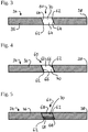
- FIG. 3 to 5 show exemplary embodiments of the conveying element 34 in a cross-sectional view.
- the conveying element 34 is preferably configured as a conveying plate 36.
- the conveying element 34 moreover has a conveying portion 60.
- the conveying portion 60 is configured for engaging the profile bar 18 in a form-fitting and/or force-fitting manner.
- the conveying portion 60 can have one or a plurality of conveying edges 62 so as to acquire the profile bar 18 in a form-fitting manner.
- the conveying edges 62 can lodge in the external circumferential face of the profile bar 18 and thus acquire the profile bar 18 in a form-fitting manner.
- the conveying portion 60 can furthermore have a conveying face 64 so as to acquire the profile bar 18 in a form-fitting and/or force-fitting manner.
- the conveying face 64 can have an elastomer coating 66, for example, as is illustrated in Fig. 4 .
- the conveying face 64 can have a knurling 68 as is illustrated in more detail in Fig. 5 .
- the conveying portion 60 can moreover have a conveying opening 70 which is dimensioned such that the profile bar 18 can be transported through the conveying opening 70.
- the conveying opening 70 preferably runs obliquely through the conveying element 34.
- the conveying opening 70 can be delimited by the conveying edge 62 and/or the conveying face 64.
- the conveying portion 60 in particular the conveying opening 70, can be shaped in such a manner that the conveying portion 60, or the conveying opening 70, respectively, interacts with the profile bar 18 such that the profile bar, when transported, by virtue of the shaping of the conveying portion 60 is rotated by an angular amount about the profile bar longitudinal axis thereof.
- the profile bar 18 can have a circular cross section which interacts with a conveying portion 60 of elliptic shape, for example.
- An interaction of a profile bar 18 which has an elliptic cross section is also conceivable.
- the profile bar 18 can furthermore have a square or rectangular cross section which can interact with an elliptic, circular, or rectangular, or square conveying portion 60, such that the profile bar 18 is rotated about the profile bar longitudinal axis thereof.
- the conveying element 34 is initially in a rotationally released state.
- the conveying element 34 in the rotationally released state in any case does not acquire the profile bar 18 in such a manner that the profile bar 18 carries out a rotation about the profile bar longitudinal axis thereof.
- the conveying element 34 in the rotationally released state is preferably completely released from the profile bar 18.
- the conveying element 34 and the profile bar 18 in the rotationally released state are preferably without mutual contact.
- the conveying element is pivoted in the conveying direction F (arrow A) until said conveying element engages the profile bar 18.
- the conveying element 34 thereafter engages the profile bar 18 in such a manner that the profile bar 18 is able to be rotated about the profile bar longitudinal axis thereof by an angular amount (arrow B).
- the conveying element 34 is in the state of rotational engagement.
- a transmission of force from the conveying element 34 to the profile bar 18 is possible in the state of rotational engagement.
- the rotation of the profile bar 18 can thus be performed by the rotating mechanism 50 in that the rotating mechanism 50 drives the conveying element 34, on the one hand.
- the profile bar 18 can also be induced to rotate about the profile bar longitudinal axis thereof on account of the special shaping of the conveying element 34, or of the conveying portion 60, respectively.
- the rotating mechanism 50 can be dispensed with.
- the rotating mechanism 50 may nevertheless be provided in a complementary manner.
- the conveying element 34 can be pivoted counter to the conveying direction F (arrow C), wherein said conveying element 34 is released from the profile bar 18 and sets the latter free.
- the conveying element 34 initially pivots (arrow A) from a conveying initial position 76 to a conveying engagement position 78 in which the conveying element 34 engages the profile bar 18 in such a manner that a sufficient transmission of force in the conveying direction F is possible such that the profile bar 18 in the movement of the conveying element 34 from the conveying engagement position 78 to the final position 74 is correspondingly moved onward in the conveying direction F.
- the conveying engagement position 78 can preferably be associated with the state of rotational engagement of the conveying element 34.
- a plurality of conveying elements 34 are preferably provided, which by alternating activation can be operated in such a manner that a uniform movement of the profile bar 18 in the conveying direction results, despite the profile bar 18 being moved only in portions by each conveying element 34.
- conveying elements 34 which are exclusively shaped such that conveying of the profile bar 18 takes place in the conveying direction F can be provided, while other conveying elements 34 which initiate a rotation of the profile bar 18 about the profile bar longitudinal axis thereof and simultaneously cause conveying of the profile bar 18 in the conveying direction F are provided.
- the profile bar 18 can be moved in the conveying direction F by pivoting movements of the conveying elements 34.
- At least two conveying elements 34 are preferably provided for continuous uniform conveying of the profile bar 18.
- the conveying elements 34 contain conveying openings 70, for example bores.
- the conveying plates 36 embodied so as to be metallic, for example, on one side can be pivoted and rotated about an axis.
- the contact with the profile bar changes at the reversal point of the conveying plate 36 such that the profile bar 18 is moved onward.
- a discrete rotation of the profile bar 18 can likewise take place so as to enable in particular the manufacturing material when depositing curved component portions.
- the speed in 3D printing can be significantly increased by way of the measures described above, since slipping of the conveying elements, for example by virtue of contaminations, can be avoided by virtue of the design embodiment of the transport mechanism. Furthermore, improved transmission of force from the conveying elements to the profile bars can take place such that the reliable conveying of the manufacturing material for the 3D printing can be maintained in the case of an increased resistance to movement.
Landscapes
- Engineering & Computer Science (AREA)
- Chemical & Material Sciences (AREA)
- Materials Engineering (AREA)
- Mechanical Engineering (AREA)
- Manufacturing & Machinery (AREA)
- Physics & Mathematics (AREA)
- Optics & Photonics (AREA)
Abstract
Description
- The invention relates to a conveying device for an additive manufacturing machine. The invention furthermore relates to a tool head for such a device and to an additive manufacturing machine.
- A typical 3D printing application in the so-called fused filament fabrication (FFF) in which a thermoplastic filament is melted and applied to a printing bed uses plastics materials. The filament may contain additives or reinforcements. The filament cools down and re-solidifies on the printing bed.
- An additive manufacturing machine which uses profile bars instead of filament is known from the not previously published
German patent application 10 2019 108 123.8 . The manufacturing machine disclosed therein uses a conventional gear wheel drive for conveying the profile bars. - The invention is based on the object of improving the production rate of additive manufacturing machines and the quality of components generated by additive manufacturing machines.
- The object is achieved by the subject matter of the independent claims. Advantageous design embodiments are the subject matter of the dependent claims.
- The invention achieves a conveying device for an additive manufacturing machine, wherein the conveying device is configured for conveying a semi-finished product which is composed of a manufacturing material that is to be processed by the additive manufacturing machine and has a semi-finished product longitudinal axis, wherein the conveying device comprises a longitudinal conveying mechanism which for conveying the semi-finished product along a conveying direction which is parallel to the semi-finished product longitudinal axis is configured in such a manner that when moving in the conveying direction the semi-finished product is able to be engaged by virtue of a periodic movement of at least one conveying element, and when moving counter to the conveying direction is able to be released from the semi-finished product, so as to move the semi-finished product in the conveying direction.
- It is preferable for the semi-finished product to be a filament and/or a profile bar, in particular a profile bar which has been pre-tailored in terms of length.
- It is preferable for the conveying element to have a conveying portion which when moving in the conveying direction is configured for engaging the semi-finished product so as to convey the semi-finished product.
- It is preferable for the conveying element to have a conveying portion which when moving counter to the conveying direction is configured for being released from the semi-finished product in such a manner that the conveying portion does not exert any conveying force in the conveying direction on the semi-finished product.
- It is preferable for the conveying portion to comprise a conveying edge and/or a conveying face. It is preferable for the conveying edge to be configured for engaging the semi-finished product in a form-fitting manner. It is preferable for the conveying face to be configured for engaging the semi-finished product in a form-fitting and/or force-fitting manner. It is preferable for the conveying face to have a friction pad for engaging the semi-finished product in a force-fitting manner. It is preferable for the conveying face to have a surface structure, for example a knurling, for engaging the semi-finished product in a form-fitting manner.
- It is preferable for the conveying element to have a conveying opening for the semi-finished product through which the semi-finished product is able to be conveyed.
- It is preferable for the conveying region, in particular the conveying edge and/or the conveying face, to be disposed on the conveying opening.
- It is preferable for the conveying region, in particular the conveying edge and/or the conveying face, to delimit the conveying opening.
- It is preferable for the conveying element to be configured as a conveying plate.
- It is preferable for the conveying element to have a bearing portion at one end of the conveying element, wherein the conveying element is pivotably mounted on the bearing region.
- The conveying device preferably comprises a plurality of conveying elements.
- It is preferable for a first conveying element and a second conveying element to be disposed and able to be driven in such a manner that a uniform conveying movement of the semi-finished product is able to be generated by virtue of the movement of the conveying elements.
- It is preferable for the conveying elements to be able to be driven in such a manner that the first conveying element and the second conveying element during the respective movement have in each case directions of movement which are at least in part counter to one another.
- It is preferable for conveying elements that are disposed so as to be adjacent in the conveying direction are configured in such a manner that in a movement in the conveying direction the semi-finished product is able to be engaged in such a manner that the semi-finished product is able to be rotated by an angular amount about the semi-finished product longitudinal axis thereof.
- It is preferable for at least one conveying element to comprise a conveying portion which is shaped in such a manner that the conveying portion when interacting with the semi-finished product rotates the latter by an angular amount about the semi-finished product longitudinal axis thereof.
- It is preferable for at least one conveying element, in particular at least one conveying region, to be configured in such a manner that the angular amount is proportional to the range of movement of the conveying element.
- The conveying device preferably comprises a rotating mechanism which is configured for rotating the semi-finished product about the semi-finished product longitudinal axis.
- It is preferable for the rotating mechanism to be configured for driving the conveying element in such a manner that the semi-finished product is able to be rotated about the semi-finished product longitudinal axis.
- It is preferable for the conveying element to be configured and/or disposed on the rotating mechanism in such a manner that the conveying element is able to be moved to a state of rotational engagement in which a rotating movement is able to be transmitted from the rotating mechanism to the semi-finished product.
- It is preferable for the conveying element to be configured and/or disposed on the rotating mechanism in such a manner that the conveying element is able to be moved to a rotationally released state in which no force which is suitable for rotating the semi-finished product about the semi-finished product longitudinal axis is able to be transmitted from the rotating mechanism to the semi-finished product.
- It is preferable for the conveying element to be configured and/or disposed on the rotating mechanism in such a manner that the conveying element is able to be moved to a longitudinally conveying state in which a conveying movement of the semi-finished product in the conveying direction is possible, wherein when moving in the conveying direction the longitudinally conveying state is preferably able to be achieved by the conveying element before the state of rotational engagement. The invention achieves a tool head for assembly and use in an additive manufacturing machine, wherein the tool head comprises an input portion for a semi-finished product which is composed of a manufacturing material that is to be processed by the additive manufacturing machine and has a semi-finished product longitudinal axis; an output portion which is configured for depositing molten manufacturing material on a printing bed so as to manufacture a component; as well as comprising a preferred conveying device that is configured for conveying the semi-finished product from the input portion to the output portion and for holding said semi-finished product on the tool head.
- The invention achieves an additive manufacturing machine which is configured for carrying out a fused deposition modeling method for manufacturing a component, in particular for an aircraft, wherein the manufacturing machine is configured for processing manufacturing material tailored so as to form profile bars, wherein the manufacturing machine comprises a preferred conveying device for conveying the semi-finished product and/or a preferred tool head for processing the semi-finished product.
- The most prevalent 3D printing application in the so-called fused filament fabrication (FFF) in which a thermoplastic filament is melted and applied to a printing bed uses plastics materials. The filament may contain additives or reinforcements. The filament cools down and re-solidifies on the printing bed.
- The filament is typically provided as a coil which is assembled close to the printing head or on an immovable location of the 3D printer. The filament herein is fed to the printing head by way of an adequate guide system, for example a Bowden cable. This enables the use of comparatively long filaments but is associated with certain limitations in terms of the filaments used.
- It can thus be a limitation that the filaments used have a rather small diameter (typically between 0.8 mm and less than 3 mm) so as to permit the winding and guiding by way of acceptable bending radii. The achievable deposition rates may be limited by virtue of the small diameter. Alternative methods such as, for example, the use of added yarns or in-situ impregnation, in particular by virtue of the additional complexity of the method, can be significantly more complex in terms of the parts quality obtainable.
- By virtue of the continuous configuration of the filaments it may additionally be necessary to carry out a cutting operation for fiber-reinforced filaments, for example when a part cannot be generated in a single uninterrupted fiber path or filament path, respectively. While cutting devices of this type do exist, this approach may be less desirable because the cutting of the fibers may pose a limitation in terms of the continuous operation of the 3D printer. This applies in particular when materials such as carbon fibers are used.
- In another case, the accumulation of degraded thermoplastic material at the exit of the printer nozzle may represent an issue.
- Furthermore, the thicker the filament the longer the latter has to be heated (or the method has to be decelerated) so as to guarantee complete melting of the filament. The risk and the prevalence of degradation may increase on account thereof. The degradation modifies the viscosity of the material, for example, such that said material can accumulate on the nozzle or be pushed into the component, this being undesirable and potentially compromising the printing quality. This is typically more critical in so-called "(endless) fiber reinforced printing" in which the cleaning of the nozzle is more complicated than in the case of an endless filament which cannot be cut directly at the nozzle.
- A printing device for layered melting with or without fiber reinforcement is known per se and comprises a printing head which is disposed so as to be able to move relative to a printing bed. The printing head can contain a filament driving installation so as to by means of a plurality of drive wheels move a filament wound on a coil toward the hot end. A cutting device by which the filament can be chopped can be provided at a location which in the direction of material flow is ahead of the hot end. If required, a filament guide can be additionally interposed between the filament driving device and the hot end. A heating element which heats the filament to melting temperature and deposits said filament on the printing bed by way of an exit nozzle is located at the hot end.
- The sequence and the functioning principle of said components may be different. The cutting device can also be dispensed with when no endless fiber reinforcement is used.
- The concepts described herein relate to the field of 3D printing. The particular focus is on different types of 3D printing such as fused filament fabrication (FFF), additive layer manufacturing (ALM), or selective laser sintering (SLS). The concepts described herein are in particular focused on increasing the deposition rate, or the positioning rate, respectively, in the printing process using non-reinforced and reinforced materials. This can in particular also relate to the so-called endless fiber reinforcements in which the length of the fiber corresponds substantially to the extent of the semi-finished product to be processed, or to the component made therefrom, respectively. The measures discussed herein are particularly suitable for the not previously published
German patent application 10 2019 108 123.8 . - Exemplary embodiments will be explained in greater detail on the basis of the attached schematic drawings, in which:
- Fig. 1
- shows an exemplary embodiment of an additive manufacturing machine;
- Fig. 2
- shows an exemplary embodiment of a tool head;
- Fig. 3 to Fig. 5
- show exemplary embodiments of conveying elements; and
- Fig. 6 to Fig. 9
- show detailed views of a conveying device in various states.
- Reference is made to
Fig. 1 which schematically shows an exemplary embodiment of anadditive manufacturing machine 10. Theadditive manufacturing machine 10 has a tool head 12 which is disposed so as to be able to move relative to aprinting bed 14. The relative movement between the tool head 12 and theprinting bed 14 herein can result from a movement of the tool head as well as from a movement of the printing bed. - The tool head 12, by means of a conveying device 24, is configured for conveying a
semi-finished product 16 which is composed of a manufacturing material and has a semi-finished product longitudinal axis, for example aprofile bar 18 having a profile bar longitudinal axis, from aninput portion 20 to anoutput portion 22. - The
input portion 20 is configured for receiving theprofile bar 18 and for feeding the latter to the conveying device 24. The conveying device 24, by virtue of control commands, conveys theprofile bar 18 to theoutput portion 22 where theprofile bar 18 is heated so as to melt, and thereafter is deposited on theprinting bed 14 or on an already existingcomponent layer 26 so as to thereafter form afurther component layer 28 and successively form the desiredcomponent 30. - Reference is in particular made to
Fig. 2 which illustrates in more detail the tool head 12, or the conveying device 24, respectively. - The conveying device 24 has a longitudinal conveying
mechanism 32. The longitudinal conveyingmechanism 32 is configured for conveying theprofile bar 18 along a conveying direction F from theinput portion 20 to theoutput portion 22. - The longitudinal conveying
mechanism 32 comprises at least one conveyingelement 34. The conveyingelement 34 is preferably configured as a conveyingplate 36. The conveyingelement 34 at one end has a bearingportion 38 on which the conveyingelement 34 is pivotably mounted. - The longitudinal conveying
mechanism 32 furthermore has a longitudinal conveyingdrive installation 40. The longitudinal conveyingdrive installation 40 is configured for driving the at least one conveyingelement 34. The longitudinal conveyingdrive installation 40 is in particular configured for driving each conveyingelement 34 individually or collectively in groups. To this end, the longitudinal conveyingdrive installation 40 can have one or a plurality of longitudinal conveyingactuators 42 and/or one or a plurality of longitudinal conveyinggearbox installations 44. - As can be seen from
Fig. 2 , the longitudinal conveyingmechanism 32 presently comprises a first conveyingelement 46 and a second conveying element 48. The first conveyingelement 46 and the second conveying element 48 are preferably able to be driven in such a manner that the first conveyingelement 46 and the second conveying element 48 can carry out pivoting movements in opposite directions. In other words, the first conveyingelement 46 and the second conveying element 48 are operatively connected to the longitudinal conveyingdrive installation 40 in such a manner that the second conveying element 48 is driven in the conveying direction F when the first conveyingelement 46 is pivoted counter to the conveying direction F. - The conveying device 24 can furthermore comprise a
rotating mechanism 50. Therotating mechanism 50 is configured for driving the longitudinal conveyingmechanism 32, in particular each conveyingelement 34, in such a manner that theprofile bar 18 can be rotated about the profile bar longitudinal axis thereof. The rotating mechanism comprises arotary actuator 52 which preferably by means of arotary gearbox installation 54 is mechanically coupled to the longitudinal conveyingmechanism 32, or to the conveyingelement 34, respectively. The output portion preferably comprises aheating region 56 so as to melt theprofile bar 18. Theoutput portion 22 can furthermore have anexit nozzle 58 which is configured for applying the manufacturing material obtained from theprofile bar 18 to theprinting bed 14 or to thecomponent layer 26, so as to shape thecomponent 30 layer-by-layer. - Reference is made to
Figs. 3 to 5 which show exemplary embodiments of the conveyingelement 34 in a cross-sectional view. - The conveying
element 34 is preferably configured as a conveyingplate 36. The conveyingelement 34 moreover has a conveyingportion 60. The conveyingportion 60 is configured for engaging theprofile bar 18 in a form-fitting and/or force-fitting manner. The conveyingportion 60 can have one or a plurality of conveyingedges 62 so as to acquire theprofile bar 18 in a form-fitting manner. The conveying edges 62 can lodge in the external circumferential face of theprofile bar 18 and thus acquire theprofile bar 18 in a form-fitting manner. - The conveying
portion 60 can furthermore have a conveyingface 64 so as to acquire theprofile bar 18 in a form-fitting and/or force-fitting manner. In order for the force-fitting connection to theprofile bar 18 to be improved, the conveyingface 64 can have anelastomer coating 66, for example, as is illustrated inFig. 4 . Alternatively or additionally, the conveyingface 64 can have aknurling 68 as is illustrated in more detail inFig. 5 . - The conveying
portion 60 can moreover have a conveyingopening 70 which is dimensioned such that theprofile bar 18 can be transported through the conveyingopening 70. The conveyingopening 70 preferably runs obliquely through the conveyingelement 34. The conveyingopening 70 can be delimited by the conveyingedge 62 and/or the conveyingface 64. - The conveying
portion 60, in particular the conveyingopening 70, can be shaped in such a manner that the conveyingportion 60, or the conveyingopening 70, respectively, interacts with theprofile bar 18 such that the profile bar, when transported, by virtue of the shaping of the conveyingportion 60 is rotated by an angular amount about the profile bar longitudinal axis thereof. - For example, the
profile bar 18 can have a circular cross section which interacts with a conveyingportion 60 of elliptic shape, for example. An interaction of aprofile bar 18 which has an elliptic cross section is also conceivable. Theprofile bar 18 can furthermore have a square or rectangular cross section which can interact with an elliptic, circular, or rectangular, or square conveyingportion 60, such that theprofile bar 18 is rotated about the profile bar longitudinal axis thereof. - The functioning mode of the conveying device 24 will be explained in more detail by means of
Figs. 6 to 9 . - As is illustrated in
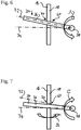
Fig. 6 , the conveyingelement 34 is initially in a rotationally released state. The conveyingelement 34 in the rotationally released state in any case does not acquire theprofile bar 18 in such a manner that theprofile bar 18 carries out a rotation about the profile bar longitudinal axis thereof. The conveyingelement 34 in the rotationally released state is preferably completely released from theprofile bar 18. In other words, the conveyingelement 34 and theprofile bar 18 in the rotationally released state are preferably without mutual contact. As is furthermore illustrated in more detail inFig. 6 , the conveying element is pivoted in the conveying direction F (arrow A) until said conveying element engages theprofile bar 18. - As is illustrated in more detail in
Fig. 7 , the conveyingelement 34 thereafter engages theprofile bar 18 in such a manner that theprofile bar 18 is able to be rotated about the profile bar longitudinal axis thereof by an angular amount (arrow B). The conveyingelement 34 is in the state of rotational engagement. A transmission of force from the conveyingelement 34 to theprofile bar 18 is possible in the state of rotational engagement. The rotation of theprofile bar 18 can thus be performed by the rotatingmechanism 50 in that therotating mechanism 50 drives the conveyingelement 34, on the one hand. On the other hand, theprofile bar 18 can also be induced to rotate about the profile bar longitudinal axis thereof on account of the special shaping of the conveyingelement 34, or of the conveyingportion 60, respectively. In this case, the rotatingmechanism 50 can be dispensed with. Therotating mechanism 50 may nevertheless be provided in a complementary manner. - Once the conveying
element 34 has moved from the rotationally releasedinitial position 72 thereof to the final position 74 thereof, the conveyingelement 34 can be pivoted counter to the conveying direction F (arrow C), wherein said conveyingelement 34 is released from theprofile bar 18 and sets the latter free. - As is illustrated in more detail in
Fig. 8 , the conveyingelement 34 initially pivots (arrow A) from a conveying initial position 76 to a conveyingengagement position 78 in which the conveyingelement 34 engages theprofile bar 18 in such a manner that a sufficient transmission of force in the conveying direction F is possible such that theprofile bar 18 in the movement of the conveyingelement 34 from the conveyingengagement position 78 to the final position 74 is correspondingly moved onward in the conveying direction F. - In the reverse pivoting (arrow C) of the conveying
element 34 from the final position 74 thereof in the direction toward the conveying initial position 76, the conveyingelement 34, in particular by virtue of the shaping of the conveyingportion 60, is released from theprofile bar 18 such that theprofile bar 18 is not moved any further. The procedure recommences in the reverse pivoting from the conveying initial position 76, conveying theprofile bar 18 piece-by-piece in the conveying direction F. - The conveying
engagement position 78 can preferably be associated with the state of rotational engagement of the conveyingelement 34. - As has already been indicated in
Fig. 2 , a plurality of conveyingelements 34 are preferably provided, which by alternating activation can be operated in such a manner that a uniform movement of theprofile bar 18 in the conveying direction results, despite theprofile bar 18 being moved only in portions by each conveyingelement 34. - It should be noted that a combination of more than two conveying
elements 34 can be used, said combination of conveyingelements 34 being adapted to the application. In other words, conveyingelements 34 which are exclusively shaped such that conveying of theprofile bar 18 takes place in the conveying direction F can be provided, while other conveyingelements 34 which initiate a rotation of theprofile bar 18 about the profile bar longitudinal axis thereof and simultaneously cause conveying of theprofile bar 18 in the conveying direction F are provided. - By virtue of the measures described above, the
profile bar 18 can be moved in the conveying direction F by pivoting movements of the conveyingelements 34. At least two conveyingelements 34, in particular in the form of conveyingplates 36, are preferably provided for continuous uniform conveying of theprofile bar 18. The conveyingelements 34 contain conveyingopenings 70, for example bores. The conveyingplates 36, embodied so as to be metallic, for example, on one side can be pivoted and rotated about an axis. By activating a plurality of conveyingelements 34 in an opposing cycle, at least part of said plurality of conveyingelements 34 is preferably in direct contact with theprofile bar 18 and pushes the latter in the direction of theexit nozzle 58, while other conveyingelements 34 are moving back to the initial position 76 thereof. The contact with the profile bar changes at the reversal point of the conveyingplate 36 such that theprofile bar 18 is moved onward. By adding further conveyingplates 36 or conveyingelements 34, respectively, a discrete rotation of theprofile bar 18 can likewise take place so as to enable in particular the manufacturing material when depositing curved component portions. In particular, can take place by virtue of the dissimilar travel distances along the curvature radius from the inside to the outside such that the application can take place in a more homogeneous manner, so as to correspond to the fiber length. - Summarizing, it is to be stated that the speed in 3D printing can be significantly increased by way of the measures described above, since slipping of the conveying elements, for example by virtue of contaminations, can be avoided by virtue of the design embodiment of the transport mechanism. Furthermore, improved transmission of force from the conveying elements to the profile bars can take place such that the reliable conveying of the manufacturing material for the 3D printing can be maintained in the case of an increased resistance to movement.
-
- 10
- additive manufacturing machine
- 12
- tool head
- 14
- printing bed
- 16
- semi-finished product
- 18
- profile bar
- 20
- input portion
- 22
- output portion
- 24
- conveying device
- 26
- component layer
- 28
- further component layer
- 30
- component
- 32
- longitudinal conveying mechanism
- 34
- conveying element
- 36
- conveying plate
- 38
- bearing region
- 40
- longitudinal conveying drive installation
- 42
- longitudinal conveying actuator
- 44
- longitudinal conveying gearbox installation
- 46
- first conveying element
- 48
- second conveying element
- 50
- rotating mechanism
- 52
- rotary actuator
- 54
- rotary gearbox installation
- 56
- heating region
- 58
- exit nozzle
- 60
- conveying region
- 62
- conveying edge
- 64
- conveying face
- 66
- elastomer coating
- 68
- knurling
- 70
- conveying opening
- 72
- rotationally released initial position
- 74
- final position
- 76
- conveying initial position
- 78
- conveying engagement position
- F
- conveying direction
Claims (15)
- A conveying device (24) for an additive manufacturing machine (10), wherein the conveying device (24) is configured for conveying a semi-finished product (16) which consists of a manufacturing material that is to be processed by the additive manufacturing machine (10) and has a semi-finished product longitudinal axis, wherein the conveying device (24) comprises a longitudinal conveying mechanism (32) configured for conveying the semi-finished product (16) along a conveying direction (F) that is parallel to the semi-finished product longitudinal axis in such a manner that, when moving in the conveying direction (F), the semi-finished product (16) is able to be engaged by virtue of a periodic movement of at least one conveying element (34, 46, 48), and when moving counter to the conveying direction (F) is able to be released from the semi-finished product (16), so as to move the semi-finished product (16) in the conveying direction (F).
- The conveying device (24) as claimed in any of the preceding claims, wherein the conveying element (34, 46, 48) has a conveying portion (60) configured, when moving in the conveying direction (F), for engaging the semi-finished product (16) so as to convey the semi-finished product (16), and/or wherein the conveying element (34, 46, 48) has a conveying portion (60) configured, when moving counter to the conveying direction (F), for being released from the semi-finished product (16) in such a manner that the conveying portion (60) does not exert any conveying force in the conveying direction (F) on the semi-finished product (16).
- The conveying device (24) as claimed in any of the preceding claims, wherein the conveying element (34, 46, 48) has a conveying opening (70) for the semi-finished product (16) through which the semi-finished product (16) is able to be conveyed.
- The conveying device (24) as claimed in any of the preceding claims, wherein the conveying portion (60) is disposed at the conveying opening (70), or wherein the conveying portion (60) delimits the conveying opening (70).
- The conveying device (24) as claimed in any of the preceding claims, wherein the conveying element (34, 46, 48) at one end of the conveying element (34, 46, 48) has a bearing portion (38), wherein the conveying element (34, 46, 48) is pivotably mounted to the bearing portion (38).
- The conveying device (24) as claimed in any of the preceding claims, comprising a plurality of conveying elements (34, 46, 48), wherein a first conveying element (46) and a second conveying element (48) are arranged and able to be driven in such a manner that a uniform conveying movement of the semi-finished product (16) is able to be generated by virtue of the movement of the conveying elements (34, 46, 48), wherein the conveying elements (34, 46, 48) are preferably able to be driven in such a manner that the first conveying element (46) and the second conveying element (48) during the respective movement have in each case directions of movement which are at least in part counter to one another.
- The conveying device (24) as claimed in any of the preceding claims, comprising a plurality of conveying elements (34, 46, 48), wherein conveying elements (34, 46, 48) that are disposed so as to be adjacent in the conveying direction (F) are configured in such a manner that the semi-finished product (16) is able to be engaged in such a manner that in a movement in the conveying direction (F) the semi-finished product (16) is able to be rotated by an angular amount about the semi-finished product longitudinal axis thereof, wherein at least one conveying element (34, 46, 48) preferably comprises a conveying portion (60) shaped in such a manner that the conveying portion (60), when interacting with the semi-finished product (16), rotates the semi-finished product (16) by an angular amount about the semi-finished product longitudinal axis thereof.
- The conveying device (24) as claimed in claim 7, wherein at least one conveying element (34, 46, 48), in particular at least one conveying portion (60) is configured in such a manner that the angular amount is proportional to the range of movement of the conveying element (34, 46, 48).
- The conveying device (24) as claimed in any of the preceding claims, comprising a rotating mechanism (50) which is configured for rotating the semi-finished product (16) about the semi-finished product longitudinal axis.
- The conveying device (24) as claimed in claim 9, characterized in that the rotating mechanism (50) is configured for driving the conveying element (34, 46, 48) in such a manner that the semi-finished product (16) is able to be rotated about the semi-finished product longitudinal axis.
- The conveying device (24) as claimed in any of the preceding claims, wherein the conveying element (34, 46, 48) is configured and/or disposed on the rotating mechanism (50) in such a manner that the conveying element (34, 46, 48) is able to be moved to a state of rotational engagement in which a rotating movement is able to be transmitted from the rotating mechanism (50) to the semi-finished product (16).
- The conveying device (24) as claimed in any of the preceding claims, wherein the conveying element (34, 46, 48) is configured and/or disposed on the rotating mechanism (50) in such a manner that the conveying element (34, 46, 48) is able to be moved to a rotationally released state in which no force that is suitable for rotating the semi-finished product (16) about the semi-finished product longitudinal axis is able to be transmitted from the rotating mechanism (50) to the semi-finished product (16).
- The conveying device (24) as claimed in any of the preceding claims, wherein the conveying element (34, 46, 48) is configured and/or disposed on the rotating mechanism (50) in such a manner that the conveying element (34, 46, 48) is able to be moved to a longitudinally conveying state in which a conveying movement of the semi-finished product (16) in the conveying direction (F) is possible, wherein when moving in the conveying direction (F) the longitudinally conveying state is preferably able to be achieved by the conveying element (34, 46, 48) before the state of rotational engagement.
- A tool head (12) for assembly and use in an additive manufacturing machine (10), wherein the tool head (12) comprises an input portion (20) for a semi-finished product (16) which consists of a manufacturing material that is to be processed by the additive manufacturing machine (10) and has a semi-finished product longitudinal axis; an output portion (22) which is configured for depositing molten manufacturing material on a printing bed (14) so as to manufacture a component (30); as well as a conveying device (24) as claimed in any of the preceding claims that is configured for conveying the semi-finished product (16) from the input portion (20) to the output portion (22) and for holding the semi-finished product (16) on the tool head (12).
- An additive manufacturing machine (10) which is configured for carrying out a fused deposition modeling method for manufacturing a component (30), in particular for an aircraft, wherein the manufacturing machine (10) is configured for processing manufacturing material tailored so as to form profile bars (16), wherein the manufacturing machine comprises a conveying device (24) as claimed in any of the claims 1 to 13 for conveying the semi-finished product (16) and/or a tool head (12) as claimed in claim 14 for processing the semi-finished product (16).
Applications Claiming Priority (1)
| Application Number | Priority Date | Filing Date | Title |
|---|---|---|---|
| DE102019116693.4A DE102019116693A1 (en) | 2019-06-19 | 2019-06-19 | Conveyor device and working head for an additive manufacturing machine and additive manufacturing machine |
Publications (2)
| Publication Number | Publication Date |
|---|---|
| EP3756861A1 true EP3756861A1 (en) | 2020-12-30 |
| EP3756861B1 EP3756861B1 (en) | 2024-01-03 |
Family
ID=71401556
Family Applications (1)
| Application Number | Title | Priority Date | Filing Date |
|---|---|---|---|
| EP20180835.9A Active EP3756861B1 (en) | 2019-06-19 | 2020-06-18 | Conveying device and tool head for an additive manufacturing machine, and additive manufacturing machine |
Country Status (4)
| Country | Link |
|---|---|
| US (1) | US11667077B2 (en) |
| EP (1) | EP3756861B1 (en) |
| DE (1) | DE102019116693A1 (en) |
| ES (1) | ES2974799T3 (en) |
Citations (3)
| Publication number | Priority date | Publication date | Assignee | Title |
|---|---|---|---|---|
| US5340433A (en) * | 1989-10-30 | 1994-08-23 | Stratasys, Inc. | Modeling apparatus for three-dimensional objects |
| US20160038655A1 (en) * | 2014-08-10 | 2016-02-11 | Louisiana Tech University Research Foundation; a Div. of Louisiana Tech University Foundation Inc. | Methods and Devices For Three-Dimensional Printing Or Additive Manufacturing Of Bioactive Medical Devices |
| DE102015122647A1 (en) * | 2015-12-22 | 2017-06-22 | Arburg Gmbh + Co. Kg | Device and method for producing a three-dimensional object with a fiber feed device |
Family Cites Families (3)
| Publication number | Priority date | Publication date | Assignee | Title |
|---|---|---|---|---|
| CN106163771B (en) | 2013-11-13 | 2019-01-11 | Abb瑞士股份有限公司 | Method and system for robot 3D printing |
| US20180243985A1 (en) * | 2016-01-19 | 2018-08-30 | Hewlett-Packard Development Company, L.P. | Extruders to feed filaments |
| US10016997B1 (en) | 2017-04-24 | 2018-07-10 | Xerox Corporation | Printer for providing multiple surface treatments to three-dimensional objects prior to printing and method for operating the printer |
-
2019
- 2019-06-19 DE DE102019116693.4A patent/DE102019116693A1/en not_active Withdrawn
-
2020
- 2020-06-17 US US16/903,498 patent/US11667077B2/en active Active
- 2020-06-18 ES ES20180835T patent/ES2974799T3/en active Active
- 2020-06-18 EP EP20180835.9A patent/EP3756861B1/en active Active
Patent Citations (3)
| Publication number | Priority date | Publication date | Assignee | Title |
|---|---|---|---|---|
| US5340433A (en) * | 1989-10-30 | 1994-08-23 | Stratasys, Inc. | Modeling apparatus for three-dimensional objects |
| US20160038655A1 (en) * | 2014-08-10 | 2016-02-11 | Louisiana Tech University Research Foundation; a Div. of Louisiana Tech University Foundation Inc. | Methods and Devices For Three-Dimensional Printing Or Additive Manufacturing Of Bioactive Medical Devices |
| DE102015122647A1 (en) * | 2015-12-22 | 2017-06-22 | Arburg Gmbh + Co. Kg | Device and method for producing a three-dimensional object with a fiber feed device |
Also Published As
| Publication number | Publication date |
|---|---|
| ES2974799T3 (en) | 2024-07-01 |
| US20200398486A1 (en) | 2020-12-24 |
| US11667077B2 (en) | 2023-06-06 |
| DE102019116693A1 (en) | 2020-12-24 |
| EP3756861B1 (en) | 2024-01-03 |
Similar Documents
| Publication | Publication Date | Title |
|---|---|---|
| EP3753708B1 (en) | Conveying device and tool head for an additive manufacturing machine, and additive manufacturing machine | |
| EP3611007B1 (en) | Print head for additive manufacturing of articles | |
| US11529748B2 (en) | System and method for cutting material in continuous fiber reinforced additive manufacturing | |
| US10118344B2 (en) | Tool head | |
| US11111626B2 (en) | Interlaced three-dimensional printed composites and machines for fabricating same | |
| US8438825B2 (en) | Head for the application of reinforcing threads on a deposition surface | |
| US11548213B2 (en) | Additive manufacturing device, additive manufacturing method, and profile rod therefor | |
| US20200324460A1 (en) | Method for fabricating multi-material structure for 3d integrated composite structures | |
| WO2020210057A1 (en) | Method for fabricating a 3d composite structure including smoothing of support structures | |
| US20200324458A1 (en) | Methods for deposition and fabrication of 3d integrated composite structures | |
| EP3756861B1 (en) | Conveying device and tool head for an additive manufacturing machine, and additive manufacturing machine | |
| US20250296282A1 (en) | Extrusion device and 3d printer | |
| US20240351279A1 (en) | Print head design for additive manufacturing using continuous fibers and thermoplastic matrix materials for cutting in the hot zone of the print head by an axial or rotational movement | |
| RU2844474C1 (en) | Print head for additive manufacturing of articles (versions) | |
| JP6764580B2 (en) | Manufacturing equipment and manufacturing method for chopped fiber bundles | |
| CN222972772U (en) | Material breaking mechanism, spray head assembly applying same and 3D printing device | |
| WO2024224269A1 (en) | Equipment and process for the three-dimensional printing of composite materials |
Legal Events
| Date | Code | Title | Description |
|---|---|---|---|
| PUAI | Public reference made under article 153(3) epc to a published international application that has entered the european phase |
Free format text: ORIGINAL CODE: 0009012 |
|
| STAA | Information on the status of an ep patent application or granted ep patent |
Free format text: STATUS: THE APPLICATION HAS BEEN PUBLISHED |
|
| AK | Designated contracting states |
Kind code of ref document: A1 Designated state(s): AL AT BE BG CH CY CZ DE DK EE ES FI FR GB GR HR HU IE IS IT LI LT LU LV MC MK MT NL NO PL PT RO RS SE SI SK SM TR |
|
| AX | Request for extension of the european patent |
Extension state: BA ME |
|
| STAA | Information on the status of an ep patent application or granted ep patent |
Free format text: STATUS: REQUEST FOR EXAMINATION WAS MADE |
|
| 17P | Request for examination filed |
Effective date: 20210628 |
|
| RBV | Designated contracting states (corrected) |
Designated state(s): AL AT BE BG CH CY CZ DE DK EE ES FI FR GB GR HR HU IE IS IT LI LT LU LV MC MK MT NL NO PL PT RO RS SE SI SK SM TR |
|
| GRAP | Despatch of communication of intention to grant a patent |
Free format text: ORIGINAL CODE: EPIDOSNIGR1 |
|
| STAA | Information on the status of an ep patent application or granted ep patent |
Free format text: STATUS: GRANT OF PATENT IS INTENDED |
|
| INTG | Intention to grant announced |
Effective date: 20230725 |
|
| GRAS | Grant fee paid |
Free format text: ORIGINAL CODE: EPIDOSNIGR3 |
|
| GRAA | (expected) grant |
Free format text: ORIGINAL CODE: 0009210 |
|
| STAA | Information on the status of an ep patent application or granted ep patent |
Free format text: STATUS: THE PATENT HAS BEEN GRANTED |
|
| AK | Designated contracting states |
Kind code of ref document: B1 Designated state(s): AL AT BE BG CH CY CZ DE DK EE ES FI FR GB GR HR HU IE IS IT LI LT LU LV MC MK MT NL NO PL PT RO RS SE SI SK SM TR |
|
| REG | Reference to a national code |
Ref country code: GB Ref legal event code: FG4D |
|
| REG | Reference to a national code |
Ref country code: CH Ref legal event code: EP |
|
| REG | Reference to a national code |
Ref country code: DE Ref legal event code: R096 Ref document number: 602020023685 Country of ref document: DE |
|
| REG | Reference to a national code |
Ref country code: IE Ref legal event code: FG4D |
|
| REG | Reference to a national code |
Ref country code: LT Ref legal event code: MG9D |
|
| REG | Reference to a national code |
Ref country code: NL Ref legal event code: MP Effective date: 20240103 |
|
| REG | Reference to a national code |
Ref country code: AT Ref legal event code: MK05 Ref document number: 1646387 Country of ref document: AT Kind code of ref document: T Effective date: 20240103 |
|
| PG25 | Lapsed in a contracting state [announced via postgrant information from national office to epo] |
Ref country code: NL Free format text: LAPSE BECAUSE OF FAILURE TO SUBMIT A TRANSLATION OF THE DESCRIPTION OR TO PAY THE FEE WITHIN THE PRESCRIBED TIME-LIMIT Effective date: 20240103 |
|
| PG25 | Lapsed in a contracting state [announced via postgrant information from national office to epo] |
Ref country code: NL Free format text: LAPSE BECAUSE OF FAILURE TO SUBMIT A TRANSLATION OF THE DESCRIPTION OR TO PAY THE FEE WITHIN THE PRESCRIBED TIME-LIMIT Effective date: 20240103 |
|
| PG25 | Lapsed in a contracting state [announced via postgrant information from national office to epo] |
Ref country code: IS Free format text: LAPSE BECAUSE OF FAILURE TO SUBMIT A TRANSLATION OF THE DESCRIPTION OR TO PAY THE FEE WITHIN THE PRESCRIBED TIME-LIMIT Effective date: 20240503 |
|
| REG | Reference to a national code |
Ref country code: ES Ref legal event code: FG2A Ref document number: 2974799 Country of ref document: ES Kind code of ref document: T3 Effective date: 20240701 |
|
| PG25 | Lapsed in a contracting state [announced via postgrant information from national office to epo] |
Ref country code: LT Free format text: LAPSE BECAUSE OF FAILURE TO SUBMIT A TRANSLATION OF THE DESCRIPTION OR TO PAY THE FEE WITHIN THE PRESCRIBED TIME-LIMIT Effective date: 20240103 |
|
| PG25 | Lapsed in a contracting state [announced via postgrant information from national office to epo] |
Ref country code: GR Free format text: LAPSE BECAUSE OF FAILURE TO SUBMIT A TRANSLATION OF THE DESCRIPTION OR TO PAY THE FEE WITHIN THE PRESCRIBED TIME-LIMIT Effective date: 20240404 |
|
| PG25 | Lapsed in a contracting state [announced via postgrant information from national office to epo] |
Ref country code: HR Free format text: LAPSE BECAUSE OF FAILURE TO SUBMIT A TRANSLATION OF THE DESCRIPTION OR TO PAY THE FEE WITHIN THE PRESCRIBED TIME-LIMIT Effective date: 20240103 Ref country code: RS Free format text: LAPSE BECAUSE OF FAILURE TO SUBMIT A TRANSLATION OF THE DESCRIPTION OR TO PAY THE FEE WITHIN THE PRESCRIBED TIME-LIMIT Effective date: 20240403 |
|
| PG25 | Lapsed in a contracting state [announced via postgrant information from national office to epo] |
Ref country code: CZ Free format text: LAPSE BECAUSE OF FAILURE TO SUBMIT A TRANSLATION OF THE DESCRIPTION OR TO PAY THE FEE WITHIN THE PRESCRIBED TIME-LIMIT Effective date: 20240103 Ref country code: AT Free format text: LAPSE BECAUSE OF FAILURE TO SUBMIT A TRANSLATION OF THE DESCRIPTION OR TO PAY THE FEE WITHIN THE PRESCRIBED TIME-LIMIT Effective date: 20240103 |
|
| PG25 | Lapsed in a contracting state [announced via postgrant information from national office to epo] |
Ref country code: RS Free format text: LAPSE BECAUSE OF FAILURE TO SUBMIT A TRANSLATION OF THE DESCRIPTION OR TO PAY THE FEE WITHIN THE PRESCRIBED TIME-LIMIT Effective date: 20240403 Ref country code: NO Free format text: LAPSE BECAUSE OF FAILURE TO SUBMIT A TRANSLATION OF THE DESCRIPTION OR TO PAY THE FEE WITHIN THE PRESCRIBED TIME-LIMIT Effective date: 20240403 Ref country code: LT Free format text: LAPSE BECAUSE OF FAILURE TO SUBMIT A TRANSLATION OF THE DESCRIPTION OR TO PAY THE FEE WITHIN THE PRESCRIBED TIME-LIMIT Effective date: 20240103 Ref country code: IS Free format text: LAPSE BECAUSE OF FAILURE TO SUBMIT A TRANSLATION OF THE DESCRIPTION OR TO PAY THE FEE WITHIN THE PRESCRIBED TIME-LIMIT Effective date: 20240503 Ref country code: HR Free format text: LAPSE BECAUSE OF FAILURE TO SUBMIT A TRANSLATION OF THE DESCRIPTION OR TO PAY THE FEE WITHIN THE PRESCRIBED TIME-LIMIT Effective date: 20240103 Ref country code: GR Free format text: LAPSE BECAUSE OF FAILURE TO SUBMIT A TRANSLATION OF THE DESCRIPTION OR TO PAY THE FEE WITHIN THE PRESCRIBED TIME-LIMIT Effective date: 20240404 Ref country code: CZ Free format text: LAPSE BECAUSE OF FAILURE TO SUBMIT A TRANSLATION OF THE DESCRIPTION OR TO PAY THE FEE WITHIN THE PRESCRIBED TIME-LIMIT Effective date: 20240103 Ref country code: BG Free format text: LAPSE BECAUSE OF FAILURE TO SUBMIT A TRANSLATION OF THE DESCRIPTION OR TO PAY THE FEE WITHIN THE PRESCRIBED TIME-LIMIT Effective date: 20240103 Ref country code: AT Free format text: LAPSE BECAUSE OF FAILURE TO SUBMIT A TRANSLATION OF THE DESCRIPTION OR TO PAY THE FEE WITHIN THE PRESCRIBED TIME-LIMIT Effective date: 20240103 |
|
| PG25 | Lapsed in a contracting state [announced via postgrant information from national office to epo] |
Ref country code: PT Free format text: LAPSE BECAUSE OF FAILURE TO SUBMIT A TRANSLATION OF THE DESCRIPTION OR TO PAY THE FEE WITHIN THE PRESCRIBED TIME-LIMIT Effective date: 20240503 Ref country code: PL Free format text: LAPSE BECAUSE OF FAILURE TO SUBMIT A TRANSLATION OF THE DESCRIPTION OR TO PAY THE FEE WITHIN THE PRESCRIBED TIME-LIMIT Effective date: 20240103 |
|
| PG25 | Lapsed in a contracting state [announced via postgrant information from national office to epo] |
Ref country code: SE Free format text: LAPSE BECAUSE OF FAILURE TO SUBMIT A TRANSLATION OF THE DESCRIPTION OR TO PAY THE FEE WITHIN THE PRESCRIBED TIME-LIMIT Effective date: 20240103 Ref country code: PT Free format text: LAPSE BECAUSE OF FAILURE TO SUBMIT A TRANSLATION OF THE DESCRIPTION OR TO PAY THE FEE WITHIN THE PRESCRIBED TIME-LIMIT Effective date: 20240503 Ref country code: PL Free format text: LAPSE BECAUSE OF FAILURE TO SUBMIT A TRANSLATION OF THE DESCRIPTION OR TO PAY THE FEE WITHIN THE PRESCRIBED TIME-LIMIT Effective date: 20240103 Ref country code: LV Free format text: LAPSE BECAUSE OF FAILURE TO SUBMIT A TRANSLATION OF THE DESCRIPTION OR TO PAY THE FEE WITHIN THE PRESCRIBED TIME-LIMIT Effective date: 20240103 |
|
| REG | Reference to a national code |
Ref country code: DE Ref legal event code: R097 Ref document number: 602020023685 Country of ref document: DE |
|
| PG25 | Lapsed in a contracting state [announced via postgrant information from national office to epo] |
Ref country code: DK Free format text: LAPSE BECAUSE OF FAILURE TO SUBMIT A TRANSLATION OF THE DESCRIPTION OR TO PAY THE FEE WITHIN THE PRESCRIBED TIME-LIMIT Effective date: 20240103 |
|
| PG25 | Lapsed in a contracting state [announced via postgrant information from national office to epo] |
Ref country code: SM Free format text: LAPSE BECAUSE OF FAILURE TO SUBMIT A TRANSLATION OF THE DESCRIPTION OR TO PAY THE FEE WITHIN THE PRESCRIBED TIME-LIMIT Effective date: 20240103 |
|
| PG25 | Lapsed in a contracting state [announced via postgrant information from national office to epo] |
Ref country code: EE Free format text: LAPSE BECAUSE OF FAILURE TO SUBMIT A TRANSLATION OF THE DESCRIPTION OR TO PAY THE FEE WITHIN THE PRESCRIBED TIME-LIMIT Effective date: 20240103 |
|
| PG25 | Lapsed in a contracting state [announced via postgrant information from national office to epo] |
Ref country code: SK Free format text: LAPSE BECAUSE OF FAILURE TO SUBMIT A TRANSLATION OF THE DESCRIPTION OR TO PAY THE FEE WITHIN THE PRESCRIBED TIME-LIMIT Effective date: 20240103 |
|
| PG25 | Lapsed in a contracting state [announced via postgrant information from national office to epo] |
Ref country code: SM Free format text: LAPSE BECAUSE OF FAILURE TO SUBMIT A TRANSLATION OF THE DESCRIPTION OR TO PAY THE FEE WITHIN THE PRESCRIBED TIME-LIMIT Effective date: 20240103 Ref country code: SK Free format text: LAPSE BECAUSE OF FAILURE TO SUBMIT A TRANSLATION OF THE DESCRIPTION OR TO PAY THE FEE WITHIN THE PRESCRIBED TIME-LIMIT Effective date: 20240103 Ref country code: RO Free format text: LAPSE BECAUSE OF FAILURE TO SUBMIT A TRANSLATION OF THE DESCRIPTION OR TO PAY THE FEE WITHIN THE PRESCRIBED TIME-LIMIT Effective date: 20240103 Ref country code: EE Free format text: LAPSE BECAUSE OF FAILURE TO SUBMIT A TRANSLATION OF THE DESCRIPTION OR TO PAY THE FEE WITHIN THE PRESCRIBED TIME-LIMIT Effective date: 20240103 Ref country code: DK Free format text: LAPSE BECAUSE OF FAILURE TO SUBMIT A TRANSLATION OF THE DESCRIPTION OR TO PAY THE FEE WITHIN THE PRESCRIBED TIME-LIMIT Effective date: 20240103 |
|
| PLBE | No opposition filed within time limit |
Free format text: ORIGINAL CODE: 0009261 |
|
| STAA | Information on the status of an ep patent application or granted ep patent |
Free format text: STATUS: NO OPPOSITION FILED WITHIN TIME LIMIT |
|
| 26N | No opposition filed |
Effective date: 20241007 |
|
| PG25 | Lapsed in a contracting state [announced via postgrant information from national office to epo] |
Ref country code: MC Free format text: LAPSE BECAUSE OF FAILURE TO SUBMIT A TRANSLATION OF THE DESCRIPTION OR TO PAY THE FEE WITHIN THE PRESCRIBED TIME-LIMIT Effective date: 20240103 |
|
| REG | Reference to a national code |
Ref country code: CH Ref legal event code: PL |
|
| PG25 | Lapsed in a contracting state [announced via postgrant information from national office to epo] |
Ref country code: LU Free format text: LAPSE BECAUSE OF NON-PAYMENT OF DUE FEES Effective date: 20240618 |
|
| PG25 | Lapsed in a contracting state [announced via postgrant information from national office to epo] |
Ref country code: IE Free format text: LAPSE BECAUSE OF NON-PAYMENT OF DUE FEES Effective date: 20240618 |
|
| PG25 | Lapsed in a contracting state [announced via postgrant information from national office to epo] |
Ref country code: CH Free format text: LAPSE BECAUSE OF NON-PAYMENT OF DUE FEES Effective date: 20240630 Ref country code: SI Free format text: LAPSE BECAUSE OF FAILURE TO SUBMIT A TRANSLATION OF THE DESCRIPTION OR TO PAY THE FEE WITHIN THE PRESCRIBED TIME-LIMIT Effective date: 20240103 Ref country code: BE Free format text: LAPSE BECAUSE OF NON-PAYMENT OF DUE FEES Effective date: 20240630 |
|
| REG | Reference to a national code |
Ref country code: BE Ref legal event code: MM Effective date: 20240630 |
|
| PGFP | Annual fee paid to national office [announced via postgrant information from national office to epo] |
Ref country code: DE Payment date: 20250618 Year of fee payment: 6 |
|
| PGFP | Annual fee paid to national office [announced via postgrant information from national office to epo] |
Ref country code: GB Payment date: 20250618 Year of fee payment: 6 |
|
| PGFP | Annual fee paid to national office [announced via postgrant information from national office to epo] |
Ref country code: FR Payment date: 20250626 Year of fee payment: 6 |
|
| PG25 | Lapsed in a contracting state [announced via postgrant information from national office to epo] |
Ref country code: FI Free format text: LAPSE BECAUSE OF FAILURE TO SUBMIT A TRANSLATION OF THE DESCRIPTION OR TO PAY THE FEE WITHIN THE PRESCRIBED TIME-LIMIT Effective date: 20240103 |
|
| PGFP | Annual fee paid to national office [announced via postgrant information from national office to epo] |
Ref country code: ES Payment date: 20250731 Year of fee payment: 6 |
|
| PGFP | Annual fee paid to national office [announced via postgrant information from national office to epo] |
Ref country code: IT Payment date: 20250624 Year of fee payment: 6 |
|
| PG25 | Lapsed in a contracting state [announced via postgrant information from national office to epo] |
Ref country code: CY Free format text: LAPSE BECAUSE OF FAILURE TO SUBMIT A TRANSLATION OF THE DESCRIPTION OR TO PAY THE FEE WITHIN THE PRESCRIBED TIME-LIMIT; INVALID AB INITIO Effective date: 20200618 |
|
| PG25 | Lapsed in a contracting state [announced via postgrant information from national office to epo] |
Ref country code: HU Free format text: LAPSE BECAUSE OF FAILURE TO SUBMIT A TRANSLATION OF THE DESCRIPTION OR TO PAY THE FEE WITHIN THE PRESCRIBED TIME-LIMIT; INVALID AB INITIO Effective date: 20200618 |