EP3756822B1 - Spindle-mounting head for a machine tool - Google Patents
Spindle-mounting head for a machine tool Download PDFInfo
- Publication number
- EP3756822B1 EP3756822B1 EP20179048.2A EP20179048A EP3756822B1 EP 3756822 B1 EP3756822 B1 EP 3756822B1 EP 20179048 A EP20179048 A EP 20179048A EP 3756822 B1 EP3756822 B1 EP 3756822B1
- Authority
- EP
- European Patent Office
- Prior art keywords
- spindle
- actuator unit
- axis
- mounting head
- oscillation
- Prior art date
- Legal status (The legal status is an assumption and is not a legal conclusion. Google has not performed a legal analysis and makes no representation as to the accuracy of the status listed.)
- Active
Links
Images

Classifications
-
- B—PERFORMING OPERATIONS; TRANSPORTING
- B23—MACHINE TOOLS; METAL-WORKING NOT OTHERWISE PROVIDED FOR
- B23Q—DETAILS, COMPONENTS, OR ACCESSORIES FOR MACHINE TOOLS, e.g. ARRANGEMENTS FOR COPYING OR CONTROLLING; MACHINE TOOLS IN GENERAL CHARACTERISED BY THE CONSTRUCTION OF PARTICULAR DETAILS OR COMPONENTS; COMBINATIONS OR ASSOCIATIONS OF METAL-WORKING MACHINES, NOT DIRECTED TO A PARTICULAR RESULT
- B23Q1/00—Members which are comprised in the general build-up of a form of machine, particularly relatively large fixed members
- B23Q1/25—Movable or adjustable work or tool supports
- B23Q1/44—Movable or adjustable work or tool supports using particular mechanisms
- B23Q1/50—Movable or adjustable work or tool supports using particular mechanisms with rotating pairs only, the rotating pairs being the first two elements of the mechanism
- B23Q1/52—Movable or adjustable work or tool supports using particular mechanisms with rotating pairs only, the rotating pairs being the first two elements of the mechanism a single rotating pair
-
- B—PERFORMING OPERATIONS; TRANSPORTING
- B23—MACHINE TOOLS; METAL-WORKING NOT OTHERWISE PROVIDED FOR
- B23Q—DETAILS, COMPONENTS, OR ACCESSORIES FOR MACHINE TOOLS, e.g. ARRANGEMENTS FOR COPYING OR CONTROLLING; MACHINE TOOLS IN GENERAL CHARACTERISED BY THE CONSTRUCTION OF PARTICULAR DETAILS OR COMPONENTS; COMBINATIONS OR ASSOCIATIONS OF METAL-WORKING MACHINES, NOT DIRECTED TO A PARTICULAR RESULT
- B23Q16/00—Equipment for precise positioning of tool or work into particular locations not otherwise provided for
- B23Q16/02—Indexing equipment
- B23Q16/022—Indexing equipment in which only the indexing movement is of importance
- B23Q16/025—Indexing equipment in which only the indexing movement is of importance by converting a continuous movement into a rotary indexing movement
-
- B—PERFORMING OPERATIONS; TRANSPORTING
- B23—MACHINE TOOLS; METAL-WORKING NOT OTHERWISE PROVIDED FOR
- B23Q—DETAILS, COMPONENTS, OR ACCESSORIES FOR MACHINE TOOLS, e.g. ARRANGEMENTS FOR COPYING OR CONTROLLING; MACHINE TOOLS IN GENERAL CHARACTERISED BY THE CONSTRUCTION OF PARTICULAR DETAILS OR COMPONENTS; COMBINATIONS OR ASSOCIATIONS OF METAL-WORKING MACHINES, NOT DIRECTED TO A PARTICULAR RESULT
- B23Q2220/00—Machine tool components
- B23Q2220/006—Spindle heads
Definitions
- This invention relates to a spindle-mounting head for a machine tool, preferably for a machining centre tilting head machining centre.
- This invention is applied in particular in the sector of mechatronics, in particular in the production of machining centres for the aeronautics and aerospace sectors.
- machining centres are divided by type and number of "operating" axes; more specifically, machining centres are known which are equipped with a tool-holder spindle rotatable about its own central axis and at the same time tilting, that is, which can be oriented, by rotation about an axis at right angles to the central axis.
- These machines typically have 5 axes or more, wherein the spindle-mounting head comprises inside it the movement system, that is to say, the orientation system, of the spindle.
- Patent document US2015/122072 forms the basis of the preamble of independent claim 1.
- Patent document US5584621 shows a first prior art solution for the movement of the spindle about the so-called "axis A", that is to say, the horizontal axis, wherein the spindle is coupled directly to an electric motor/torque motor.
- This solution does allow a high dynamic level, free of clearances, but does not allow the generation of high torques keeping the dimensions of the head reduced, an essential specification in certain applications, such as, for example, that of aeronautics.
- a further prior art solution comprises a screw-gear coupling, wherein the gear is connected directly to the spindle whilst the screw is moved, either directly or by means of gear wheels or belts, by the motor.
- the motion between the motor and the spindle is transmitted by means of a transmission system with gears/gear wheels positioned in cascade fashion.
- the motor is coupled to a cascade of gear wheels which following a series of reductions transmit the rotational motion to a gear constrained to the spindle.
- this solution is bulky and structurally complex, since it has to provide numerous gear wheels along at least two distinct branches, one of which is in turn equipped with a preloading system for recovering the clearance.
- the transmissible torque is also a critical parameter and limited.
- the aim of this invention is therefore to provide a spindle-mounting head for a machine tool which overcomes the above-mentioned drawbacks of the prior art.
- the aim of the invention is to provide a spindle-mounting head for a machine tool which combines a high level of working precision with a limited size.
- the aim of the invention is to provide a spindle-mounting head for a machine tool which minimises clearances and has a high thermal and structural symmetry.
- a spindle-mounting head for a machine tool having the features described in one or more of the appended claims and in particular comprising a supporting body, a tool-mounting spindle and movement means.
- the supporting body comprises at least a first and a second arm protruding from a base portion and defining a fork-shaped structure.
- the tool-mounting spindle is at least partly housed in said fork-shaped structure and rotatably connected to said first arm and second arm to rotate about an axis of oscillation.
- the spindle comprises a tool-mounting body rotatable about a relative machining axis at right angles to said axis of oscillation.
- the movement means are operatively interposed between the supporting body and the spindle to rotate it about said axis of oscillation.
- the movement means comprise a first actuator unit and a second actuator unit housed, respectively, in the first arm and in the second arm and both configured for rotating the spindle about the axis of oscillation.
- Each actuator unit comprises a rotary motor configured to generate a drive torque and a reduction gear unit coupled to said rotary motor and configured to provide to an outlet shaft a transmitted torque greater than the drive torque.
- the outlet shaft is oriented transversely to the axis of oscillation.
- each actuator unit there is a bevel gear equipped with a first wheel keyed on said outlet shaft and a second wheel constrained to said spindle and coaxial with said axis of oscillation.
- said first and said second actuator unit are configured to generate, on the axis of oscillation, respective transmitted torques unbalanced with respect to each other, so as to eliminate the clearance in the kinematic chains.
- the two actuator units are controlled according to a master-slave mode.
- the first actuator unit is preferably controlled in position, that is to say, following a reference defining an angular position.
- the second actuator unit is preferably driven in torque, that is to say, by following a torque reference associated with the torque generated by the first actuator unit.
- the second actuator unit is controlled with a torque equal to the torque generated by the first actuator unit reduced by a constant.
- the numeral 1 denotes a spindle-mounting head for a machine tool 100 according to this invention.
- the spindle-mounting head 1 is located in machining centres 100 with a tilting head, that is to say, with spindle-mounting head which is able to vary its orientation relative to an axis of rotation (or axis of oscillation "A") which is typically, but not exclusively, horizontal.
- the machining centre, or machine tool 100 comprises a part-holder table 101, generally rotatable about its own axis and/or movable along one or more directions of movements.
- the table is associated with a frame 102 from which extends a supporting structure or upright 103 for the spindle-mounting head 1. Said upright 103 is alongside the part-holder table 101 and extends at right angles to it along a substantially vertical direction.
- the upright 103 in turn may be movable along one or more axes of movement relative to the table.
- the upright 103 is also associated with the spindle-mounting head 1, preferably in a movable fashion along the upright so as to vary the height of the spindle relative to the part-holder table 101.
- the spindle-mounting head 1 comprises a supporting body 2 equipped with a first arm 3 and a second arm 4 protruding from a base portion 5 and defining a fork-shaped structure.
- the base portion 5 of the supporting body 2 is slidably constrained to the upright 103 for translating along said substantially vertical direction.
- the two arms 3, 4 extend substantially parallel to each other starting from two spaced portions of the base 5 in such a way as to face each other. A housing space is thus defined between the two arms 3, 4.
- a tool-mounting spindle is at least partly rotatably housed in the fork-shaped structure of the supporting body 2, in particular inside said housing space.
- the tool-mounting spindle 6 is rotatably connected to the first arm 3 and to the second arm 4 to rotate about an axis of oscillation "A" (or tilt axis).
- the spindle 6 comprises a tool-mounting body 6a rotatable about its own machining axis "B" at right angles to the axis of oscillation "A".
- the spindle 6 is an electric spindle, that is to say, a spindle equipped with at least one rotor-stator pack inside it, with a rotor (not illustrated) preferably keyed directly on the shaft for retaining the tool.
- the spindle 6 comprises a containment body 6b inside of which are housed a stator, a rotor and a transmission shaft coupled to said rotor.
- the transmission shaft is rotatable inside the containment body and coupled to a pack of bearings, preferably two.
- the tool-mounting head 1 also comprises movement means 7 operatively interposed between the supporting body 2 and the spindle 6 for rotating it about said axis of oscillation "A".
- the movement means 7 are designed to allow oscillation of the spindle about the axis "A" (as mentioned preferably, horizontal).
- the movement means 7 comprise a first actuator unit 8 and a second actuator unit 9 housed, respectively, in the first arm 3 and in the second arm 4 and both configured for rotating the spindle 6 about the axis of oscillation "A".
- the presence of two actuator units 8, 9 complementary to each other and positioned in the two arms 3, 4 of the supporting body makes it possible to balance better the structure of the machine and to guarantee the minimising of the clearances.
- control unit 13 associated with the actuator units 8, 9 and configured for controlling them in a complementary fashion for moving the spindle about the axis of oscillation "A" and at the same time reducing the clearances.
- the first 8 and the second 9 actuator units are configured to generate on the axis of oscillation "A" respective torques transmitted to each other in an unbalanced fashion so as to eliminate the clearance in the kinematic chains.
- control unit 13 is configured for controlling the first 8 and the second 9 actuator units in such a way as to generate transmitted torques which are slightly unbalanced with each other and such as to determine a sufficient preloading to reduce the clearances of the kinematic chain.
- the two actuator units are controlled according to a master-slave mode.
- the first actuator unit 8 is preferably controlled in position, that is to say, following a reference defining an angular position.
- the second actuator unit 9 is preferably driven in torque, that is to say, by following a torque reference associated with the torque generated by the first actuator unit 9.
- the second actuator unit 9 is controlled with a torque equal to the torque generated by the first actuator unit 8 reduced by a constant.
- this constant is part of the nominal torque which can be generated by the first actuator 9, preferably between 2% and 10% of said nominal torque.
- the operating field of the machine which ranges from a negative maximum value to a positive maximum value of the torque which can be generated, will have three different operating zones.
- both the torques generated by the first 8 and the second 9 actuator unit have the same orientation, generating concordant torques in a first direction of rotation.
- both the torques by the first 8 and the second 9 actuator unit again have the same orientation, generating concordant torques in a second direction of rotation, opposite to the first.
- the torque generated by the first actuator unit 8 has the opposite direction relative to that generated by the second actuator unit 9. In this way, a preloading is generated on the transmission and the gears operate on opposite sides.
- both the actuator units 8, 9 contribute to satisfy the load and can be used for "heavy" or roughing processing, which do not require preloading of the axis.
- each actuator unit 8, 9 comprises a rotary motor 10 configured to generate a drive torque and a reduction gear unit 11 coupled to the rotary motor 10.
- the reduction gear unit 11 is configured for providing to an outlet shaft 11a a transmitted torque greater than said drive torque generated by the rotary motor 10.
- the motor 10 and the reduction gear unit 11 define a gear motor.
- the outlet shaft 11a is oriented transversely, more preferably at right angles, to the axis of oscillation "A".
- the actuator units 8, 9 each comprise a bevel gear 12 equipped with a first (conical) wheel 12a keyed on the outlet shaft 11a and a second (conical) wheel 12b connected to the spindle 6 and coaxial with said axis of oscillation "A".
- the second wheel 12b is connected to the containment body 6b of the spindle, more specifically to a lateral flank of the spindle.
- the bevel gears 12 preferably have the same transmission ratio, more preferably between 3 and 10.
- the first 8 and the second 9 actuator unit are positioned symmetrically relative to a mid-plane of the supporting body 2 at right angles to said axis of oscillation "A" and comprising said operating axis "B".
- the two actuator units have motors 10, reduction gear units 11 and bevel gears 12 positioned specularly to each other, so as to facilitate the design, maintenance and assembly of the head 1, as well as guaranteeing thermal and structural balancing.
- the supporting body 2 has a supporting frame 15 defining the anchors for the actuator units and the seats for the rotation bearings of the spindle 6.
- the supporting body 2 comprises at least one supporting plate 14 housed both in the first arm 3 and in the second arm 4. More specifically, at the first arm 3 and the second arm 4 it has respective supporting plates 14.
- Each support plate 14 has at least one first face 14a and a second face 14b opposite to each other and both transversal to said axis of oscillation "A".
- the plates 14 have a first face oriented towards the spindle 6 and a second face 14b oriented away from the spindle 6.
- the plate 14 is located in the proximity of the second wheel (conical) 12b of the bevel gear 12.
- each actuator unit 8, 9 is connected to the plate 14, in such a way as to have a rigid connection close to the transmission zone of the torque.
- the motor 10 or the reduction gear unit 11 are connected directly to one of either the first face 14a or the second face 14b of the respective plate 14.
- the motor 10 or the reduction gear unit 11 of each actuator unit 8, 9 are connected to the second face 14b of the respective plate 14.
- the reduction gear unit 11 is constrained to the respective face of the plate 14, with the outlet shaft 12 and the motor 10 extending away from each other and in a cantilever fashion relative to the plate 14.
- the plate 14 preferably comprises at least one fastening area "Z" for the respective motor 10 or reduction gear unit 11.
- Each fastening area “Z” comprises means (not illustrated) for finely adjusting the position of the respective motor 10 or reduction gear unit 11, preferably defined by slots or by screw regulating means.
- the motor 10/reduction gear unit 11 (or gear motor) is of the linear type.
- said rotary motor 10 of each actuator unit 8, 9 comprises a drive shaft parallel to said outlet shaft 12 of the reduction gear unit 11.
- both the gear motors extend in a straight line away from the axis of oscillation "A" and at right angles to it; this maximises the volumetric occupation of arms 3, 4, reducing the overall dimensions of the head.
- the invention achieves the above mentioned aims and brings important advantages.
- the location of two gear motors with bevel gear transmission on opposite sides of the spindle allows, on the one hand, to have a high dynamic level in the motion with equally high torque transmitted, and, on the other hand, eliminates clearance in a simple manner whilst keeping the overall dimensions small.
Landscapes
- Engineering & Computer Science (AREA)
- Mechanical Engineering (AREA)
- Machine Tool Units (AREA)
Description
- This invention relates to a spindle-mounting head for a machine tool, preferably for a machining centre tilting head machining centre.
- This invention is applied in particular in the sector of mechatronics, in particular in the production of machining centres for the aeronautics and aerospace sectors.
- In the prior art, the machining centres are divided by type and number of "operating" axes; more specifically, machining centres are known which are equipped with a tool-holder spindle rotatable about its own central axis and at the same time tilting, that is, which can be oriented, by rotation about an axis at right angles to the central axis. These machines typically have 5 axes or more, wherein the spindle-mounting head comprises inside it the movement system, that is to say, the orientation system, of the spindle.
- Patent document
US2015/122072 forms the basis of the preamble ofindependent claim 1. Patent documentUS5584621 , shows a first prior art solution for the movement of the spindle about the so-called "axis A", that is to say, the horizontal axis, wherein the spindle is coupled directly to an electric motor/torque motor. - This solution does allow a high dynamic level, free of clearances, but does not allow the generation of high torques keeping the dimensions of the head reduced, an essential specification in certain applications, such as, for example, that of aeronautics.
- A further prior art solution comprises a screw-gear coupling, wherein the gear is connected directly to the spindle whilst the screw is moved, either directly or by means of gear wheels or belts, by the motor.
- That solution, whilst it is inexpensive and generally not bulky, has several drawbacks linked to the presence of clearances, which are intrinsic in the screw-gear coupling, which, if they are to be limited or eliminated, lead to an increase in friction, with consequent critical issues in terms of machining speed and wear.
- According to another prior art solution the motion between the motor and the spindle is transmitted by means of a transmission system with gears/gear wheels positioned in cascade fashion.
- More precisely, the motor is coupled to a cascade of gear wheels which following a series of reductions transmit the rotational motion to a gear constrained to the spindle.
- In these solutions there are systems for recovery of the clearance of the elastic type (i.e. springs) or hydraulic type, applied to one of the branches of the cascade of gears, which allow maximum operating precision.
- Disadvantageously, this solution is bulky and structurally complex, since it has to provide numerous gear wheels along at least two distinct branches, one of which is in turn equipped with a preloading system for recovering the clearance.
- Moreover, since it is a single cascade of gears which gives the torque and the preloading, the transmissible torque is also a critical parameter and limited.
- The aim of this invention is therefore to provide a spindle-mounting head for a machine tool which overcomes the above-mentioned drawbacks of the prior art.
- In particular, the aim of the invention is to provide a spindle-mounting head for a machine tool which combines a high level of working precision with a limited size.
- Moreover, the aim of the invention is to provide a spindle-mounting head for a machine tool which minimises clearances and has a high thermal and structural symmetry.
- Said aims are achieved by a spindle-mounting head for a machine tool having the features described in one or more of the appended claims and in particular comprising a supporting body, a tool-mounting spindle and movement means.
- The supporting body comprises at least a first and a second arm protruding from a base portion and defining a fork-shaped structure.
- The tool-mounting spindle is at least partly housed in said fork-shaped structure and rotatably connected to said first arm and second arm to rotate about an axis of oscillation.
- The spindle comprises a tool-mounting body rotatable about a relative machining axis at right angles to said axis of oscillation.
- The movement means are operatively interposed between the supporting body and the spindle to rotate it about said axis of oscillation.
- According to an aspect of the invention, the movement means comprise a first actuator unit and a second actuator unit housed, respectively, in the first arm and in the second arm and both configured for rotating the spindle about the axis of oscillation.
- Each actuator unit comprises a rotary motor configured to generate a drive torque and a reduction gear unit coupled to said rotary motor and configured to provide to an outlet shaft a transmitted torque greater than the drive torque. The outlet shaft is oriented transversely to the axis of oscillation.
- For each actuator unit there is a bevel gear equipped with a first wheel keyed on said outlet shaft and a second wheel constrained to said spindle and coaxial with said axis of oscillation.
- Advantageously, thanks to this solution it is possible to optimise the control of the oscillation movement of the spindle, balancing the machine both from the structural and thermal point of view.
- In this regard, preferably, said first and said second actuator unit are configured to generate, on the axis of oscillation, respective transmitted torques unbalanced with respect to each other, so as to eliminate the clearance in the kinematic chains.
- More specifically, the two actuator units are controlled according to a master-slave mode.
- The first actuator unit is preferably controlled in position, that is to say, following a reference defining an angular position.
- The second actuator unit is preferably driven in torque, that is to say, by following a torque reference associated with the torque generated by the first actuator unit.
- Preferably, the second actuator unit is controlled with a torque equal to the torque generated by the first actuator unit reduced by a constant.
- These and other features and the relative advantages will become more apparent from the following non-limiting description of a preferred embodiment of a spindle-mounting head for a machine tool as illustrated in the accompanying drawings, in which:
-
Figures 1 and 2 are two specular perspective views of the spindle-mounting head according to the invention, with some parts cut away to better illustrate others; -
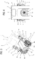
Figure 3 shows the same perspective view ofFigure 1 with the entire structure of the spindle-mounting head transparent; -
Figure 4 shows a front view of the spindle-mounting head ofFigure 1 ; -
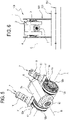
Figure 5 shows a portion of the head ofFigure 1 isolated from the rest of the structure; -
Figure 6 is schematic representation of a machine tool comprising the spindle-mounting head according to the invention. - With reference to the accompanying drawings, the
numeral 1 denotes a spindle-mounting head for amachine tool 100 according to this invention. - The spindle-mounting
head 1 is located inmachining centres 100 with a tilting head, that is to say, with spindle-mounting head which is able to vary its orientation relative to an axis of rotation (or axis of oscillation "A") which is typically, but not exclusively, horizontal. - The machining centre, or
machine tool 100, comprises a part-holder table 101, generally rotatable about its own axis and/or movable along one or more directions of movements. - The table is associated with a
frame 102 from which extends a supporting structure or upright 103 for the spindle-mountinghead 1. Said upright 103 is alongside the part-holder table 101 and extends at right angles to it along a substantially vertical direction. - The upright 103 in turn may be movable along one or more axes of movement relative to the table.
- The upright 103 is also associated with the spindle-mounting
head 1, preferably in a movable fashion along the upright so as to vary the height of the spindle relative to the part-holder table 101. - The spindle-mounting
head 1 comprises a supportingbody 2 equipped with afirst arm 3 and asecond arm 4 protruding from abase portion 5 and defining a fork-shaped structure. - The
base portion 5 of the supportingbody 2 is slidably constrained to the upright 103 for translating along said substantially vertical direction. - The two
arms base 5 in such a way as to face each other. A housing space is thus defined between the twoarms - A tool-mounting spindle is at least partly rotatably housed in the fork-shaped structure of the supporting
body 2, in particular inside said housing space. - Preferably, the tool-
mounting spindle 6 is rotatably connected to thefirst arm 3 and to thesecond arm 4 to rotate about an axis of oscillation "A" (or tilt axis). - The
spindle 6 comprises a tool-mountingbody 6a rotatable about its own machining axis "B" at right angles to the axis of oscillation "A". - Preferably, the
spindle 6 is an electric spindle, that is to say, a spindle equipped with at least one rotor-stator pack inside it, with a rotor (not illustrated) preferably keyed directly on the shaft for retaining the tool. - For this reason, in the preferred embodiment the
spindle 6 comprises acontainment body 6b inside of which are housed a stator, a rotor and a transmission shaft coupled to said rotor. - The transmission shaft is rotatable inside the containment body and coupled to a pack of bearings, preferably two.
- At its free end there is a portion for retaining/constraining a processing tool (not illustrated), defining said tool-mounting
body 6a. - The tool-
mounting head 1 also comprises movement means 7 operatively interposed between the supportingbody 2 and thespindle 6 for rotating it about said axis of oscillation "A". - The movement means 7 are designed to allow oscillation of the spindle about the axis "A" (as mentioned preferably, horizontal).
- According to an aspect of the invention, the movement means 7 comprise a
first actuator unit 8 and asecond actuator unit 9 housed, respectively, in thefirst arm 3 and in thesecond arm 4 and both configured for rotating thespindle 6 about the axis of oscillation "A". - Advantageously, the presence of two
actuator units arms - There is also a
control unit 13 associated with theactuator units - Preferably, in this regard, the first 8 and the second 9 actuator units are configured to generate on the axis of oscillation "A" respective torques transmitted to each other in an unbalanced fashion so as to eliminate the clearance in the kinematic chains.
- More specifically, the
control unit 13 is configured for controlling the first 8 and the second 9 actuator units in such a way as to generate transmitted torques which are slightly unbalanced with each other and such as to determine a sufficient preloading to reduce the clearances of the kinematic chain. - Preferably, the two actuator units are controlled according to a master-slave mode.
- The
first actuator unit 8 is preferably controlled in position, that is to say, following a reference defining an angular position. - The
second actuator unit 9 is preferably driven in torque, that is to say, by following a torque reference associated with the torque generated by thefirst actuator unit 9. - Preferably, the
second actuator unit 9 is controlled with a torque equal to the torque generated by thefirst actuator unit 8 reduced by a constant. - In the preferred embodiment, this constant is part of the nominal torque which can be generated by the
first actuator 9, preferably between 2% and 10% of said nominal torque. - For this reason, the operating field of the machine, which ranges from a negative maximum value to a positive maximum value of the torque which can be generated, will have three different operating zones.
- In a first, negative working zone, both the torques generated by the first 8 and the second 9 actuator unit have the same orientation, generating concordant torques in a first direction of rotation.
- In a second, positive working zone, both the torques by the first 8 and the second 9 actuator unit again have the same orientation, generating concordant torques in a second direction of rotation, opposite to the first.
- In a third operating zone, interposed between the first and the second, the torque generated by the
first actuator unit 8 has the opposite direction relative to that generated by thesecond actuator unit 9. In this way, a preloading is generated on the transmission and the gears operate on opposite sides. - Advantageously, therefore, in the first and second operating zones, in which high torques are generated (in absolute value), both the
actuator units - On the other hand, in the third zone, in which limited torques are generated (in absolute value), it is possible to perform precision (finishing) operations which require low torque and low clearance/high rigidity of the transmission.
- Preferably, each
actuator unit rotary motor 10 configured to generate a drive torque and areduction gear unit 11 coupled to therotary motor 10. - The
reduction gear unit 11 is configured for providing to anoutlet shaft 11a a transmitted torque greater than said drive torque generated by therotary motor 10. - Preferably, in the preferred embodiments, the
motor 10 and thereduction gear unit 11 define a gear motor. - Preferably, the
outlet shaft 11a is oriented transversely, more preferably at right angles, to the axis of oscillation "A". - In order to transmit the rotational motion to the
spindle 6, theactuator units bevel gear 12 equipped with a first (conical)wheel 12a keyed on theoutlet shaft 11a and a second (conical)wheel 12b connected to thespindle 6 and coaxial with said axis of oscillation "A". - In particular, the
second wheel 12b is connected to thecontainment body 6b of the spindle, more specifically to a lateral flank of the spindle. - The bevel gears 12 preferably have the same transmission ratio, more preferably between 3 and 10.
- Structurally, the first 8 and the second 9 actuator unit are positioned symmetrically relative to a mid-plane of the supporting
body 2 at right angles to said axis of oscillation "A" and comprising said operating axis "B". - More specifically, the two actuator units have
motors 10,reduction gear units 11 andbevel gears 12 positioned specularly to each other, so as to facilitate the design, maintenance and assembly of thehead 1, as well as guaranteeing thermal and structural balancing. - Preferably, the supporting
body 2 has a supportingframe 15 defining the anchors for the actuator units and the seats for the rotation bearings of thespindle 6. - At the axis of oscillation "A" there are at least two supports connected to respective bearings (the latter connected to the
second wheel 12b of the bevel gears 12). - Two
plates 14 are, on the other hand, housed inside thefirst arm 3 and thesecond arm 4. Thus, the supportingbody 2 comprises at least one supportingplate 14 housed both in thefirst arm 3 and in thesecond arm 4. More specifically, at thefirst arm 3 and thesecond arm 4 it has respective supportingplates 14. - Each
support plate 14 has at least onefirst face 14a and asecond face 14b opposite to each other and both transversal to said axis of oscillation "A". - The
plates 14 have a first face oriented towards thespindle 6 and asecond face 14b oriented away from thespindle 6. - It should be noted that, preferably, the
plate 14 is located in the proximity of the second wheel (conical) 12b of thebevel gear 12. - In this regard, the
rotary motor 10 or the reduction gear unit 11 (if necessary both) of eachactuator unit plate 14, in such a way as to have a rigid connection close to the transmission zone of the torque. - Preferably, the
motor 10 or thereduction gear unit 11 are connected directly to one of either thefirst face 14a or thesecond face 14b of therespective plate 14. - In the preferred embodiment, the
motor 10 or thereduction gear unit 11 of eachactuator unit second face 14b of therespective plate 14. - Preferably, the
reduction gear unit 11 is constrained to the respective face of theplate 14, with theoutlet shaft 12 and themotor 10 extending away from each other and in a cantilever fashion relative to theplate 14. - In this regard, the
plate 14 preferably comprises at least one fastening area "Z" for therespective motor 10 orreduction gear unit 11. - Each fastening area "Z" comprises means (not illustrated) for finely adjusting the position of the
respective motor 10 orreduction gear unit 11, preferably defined by slots or by screw regulating means. - In the preferred embodiment, the
motor 10/reduction gear unit 11 (or gear motor) is of the linear type. - In other words, said
rotary motor 10 of eachactuator unit outlet shaft 12 of thereduction gear unit 11. Advantageously, in this way both the gear motors extend in a straight line away from the axis of oscillation "A" and at right angles to it; this maximises the volumetric occupation ofarms - The invention achieves the above mentioned aims and brings important advantages.
- In effect, the location of two gear motors with bevel gear transmission on opposite sides of the spindle allows, on the one hand, to have a high dynamic level in the motion with equally high torque transmitted, and, on the other hand, eliminates clearance in a simple manner whilst keeping the overall dimensions small.
- Advantageously, moreover, in applications with an electro-spindle it is possible to optimise the occupation of the structure, reducing the overall dimensions and also balancing it both from the point of view of the masses and the forces involved.
Claims (11)
- Spindle-mounting head for a machine tool comprising:- a supporting body (2), comprising at least a first (3) and a second arm (4) protruding from a base portion (5) and defining a fork-shaped structure;- a tool-mounting spindle (6) at least partly housed in said fork-shaped structure and rotatably connected to said first arm (3) and second arm (4) to rotate about an axis of oscillation (A); said spindle (6) comprising a tool-mounting body (6a) rotatable about a relative machining axis (S) at right angles to said axis of oscillation (A);- movement means (7) operatively interposed between the supporting body (2) and said spindle (6) to rotate it about said axis of oscillation (A);wherein the movement means (7) comprise a first actuator unit (8) and a second actuator unit (9) housed, respectively, in the first arm (3) and in the second arm (4) and both configured for rotating the spindle (6) about the axis of oscillation (A), wherein each actuator unit (8, 9) comprises:- a rotary motor (10) configured to generate a drive torque;- a reduction gear unit (11) coupled to said rotary motor (10) and configured to supply to an output shaft (11a) a transmitted torque greater than said drive torque; characterized in that said outlet shaft (11a) being oriented transversely to said axis of oscillation (A);- a bevel gear (12) equipped with a first wheel (12a) keyed to said outlet shaft (11a) and a second wheel (12b) connected to said spindle (6) and coaxial with said axis of oscillation (A).
- The spindle-mounting head according to claim 1, wherein said first actuator unit (8) and second actuator unit (9) are configured to generate on the axis of oscillation (A) respective transmitted torques balanced between them to annul the clearance of the kinematic chains.
- The spindle-mounting head according to claim 1 or 2, wherein said first actuator unit (9) and second actuator unit (9) are controlled according to a master-slave mode.
- The spindle-mounting head according to claim 3, wherein the second actuator unit (9) is controlled with a torque equal to the torque generated by the first actuator unit (8) reduced by a constant, preferably between 2% and 10% of a nominal torque of said first actuator unit (8).
- The spindle-mounting head according to any one of the preceding claims, wherein the supporting body (2) comprises at least one supporting plate (14) housed in each first arm (3) and second arm (4) and having at least a first face (14a) and a second face (14b) opposite to each other and both transversal to said axis of oscillation (A), wherein the motor (10) and/or the reduction gear unit (11) of each actuator unit (8, 9) is constrained to the first face (14a) or to the second face (14b) of the respective plate (14).
- The spindle-mounting head according to claim 5, wherein the first face (14a) and the second face (14b) of each supporting plate (14) are oriented, respectively, in the direction of and away from the spindle (6); said motor (10) and/or said reduction gear unit (11) of each actuator unit (8, 9) being constrained to the second face (14b) of the respective plate (14).
- The spindle-mounting head according to claim 5 or 6, wherein each actuator unit (8, 9) comprises a gear motor defined by the motor (10) and by the respective reduction gear unit (11), wherein the reduction gear unit (11) is connected to the respective first face (14a) or second face (14b) of the plate (14) with said outlet shaft (11a) and said motor (10) extending away from each other and in a cantilever fashion from said plate (14).
- The spindle-mounting head according to any one of the preceding claims, wherein said rotary motor (10) of each actuator unit (8, 9) comprises a drive shaft (10) parallel to said outlet shaft (11a) of the reduction gear unit (11).
- The spindle-mounting head according to any one of the preceding claims, wherein said first actuator unit (8) and said second actuator unit (9) are positioned symmetrically relative to a mid-plane of the supporting body (2) at right angles to said axis of oscillation (A) and comprising said machining axis (B).
- The spindle-mounting head according to any one of the preceding claims, wherein said spindle (6) is an electro-spindle.
- A machine tool comprising:- a part holding device (101);- at least one upright (103) alongside said part holding device (101) extending orthogonally to it along a substantially vertical direction;- a spindle-mounting head (1) according to any one of the preceding claims, wherein the base portion (5) of the supporting body (2) is slidably constrained to said upright (103) for translating along said substantially vertical direction.
Applications Claiming Priority (1)
| Application Number | Priority Date | Filing Date | Title |
|---|---|---|---|
| IT201900008664 | 2019-06-11 |
Publications (2)
| Publication Number | Publication Date |
|---|---|
| EP3756822A1 EP3756822A1 (en) | 2020-12-30 |
| EP3756822B1 true EP3756822B1 (en) | 2022-03-30 |
Family
ID=68234135
Family Applications (1)
| Application Number | Title | Priority Date | Filing Date |
|---|---|---|---|
| EP20179048.2A Active EP3756822B1 (en) | 2019-06-11 | 2020-06-09 | Spindle-mounting head for a machine tool |
Country Status (2)
| Country | Link |
|---|---|
| EP (1) | EP3756822B1 (en) |
| ES (1) | ES2916079T3 (en) |
Families Citing this family (1)
| Publication number | Priority date | Publication date | Assignee | Title |
|---|---|---|---|---|
| EP4711076A1 (en) * | 2024-09-12 | 2026-03-18 | Starrag GmbH | Pivoting unit for a machine tool |
Family Cites Families (5)
| Publication number | Priority date | Publication date | Assignee | Title |
|---|---|---|---|---|
| GB2215243B (en) * | 1988-02-24 | 1992-02-26 | Jobs Spa | A chuck head for automatic machine tools. |
| US5584621A (en) | 1995-06-13 | 1996-12-17 | Bertsche Engineering Corp. | Direct drive multiple axes rotary spindle head for milling machine |
| DE102010054636A1 (en) * | 2010-12-17 | 2012-06-21 | Rüdiger Schrott | Compact milling head for machine tool, has two-axis rotary head and spindle unit, where supporting unit rotates around axis of rotation and spindle unit rotates around another axis of rotation |
| TWI516335B (en) * | 2013-11-05 | 2016-01-11 | 財團法人工業技術研究院 | Carrying module |
| ITUB20154125A1 (en) * | 2015-10-05 | 2017-04-05 | Mandelli Sistemi S P A | SPINDLE HOLDER HEAD FOR A TOOL MACHINE. |
-
2020
- 2020-06-09 ES ES20179048T patent/ES2916079T3/en active Active
- 2020-06-09 EP EP20179048.2A patent/EP3756822B1/en active Active
Also Published As
| Publication number | Publication date |
|---|---|
| ES2916079T3 (en) | 2022-06-28 |
| EP3756822A1 (en) | 2020-12-30 |
Similar Documents
| Publication | Publication Date | Title |
|---|---|---|
| US7065848B2 (en) | Crankshaft production machine | |
| US8899889B2 (en) | Table unit for machine tool | |
| CN104607982B (en) | Dual rotation driving device | |
| US6533508B1 (en) | Machining apparatus and machining method | |
| CN105517754B (en) | The feeding shaft device of lathe | |
| EP3359332B1 (en) | Spindle mounting head for a machine tool | |
| EP3756822A1 (en) | Spindle-mounting head for a machine tool | |
| CN102974900A (en) | Rotational motion clearance eliminating mechanism for working table of gear hobbing machine | |
| CN1361724A (en) | Method and feed device for realizing a feed movement of at least one tool holder rotating around a rotationally symmetrical component | |
| CN108747438A (en) | Linear drives rotary table | |
| JP5052655B2 (en) | Machine Tools | |
| EP2958706B1 (en) | Machine tool comprising a machining head | |
| CN113199265A (en) | Diaxon cradle formula numerical control revolving stage | |
| CN101543921B (en) | Universal cyclone milling head | |
| JP5728792B2 (en) | Gear mechanism | |
| CN111687750A (en) | Synchronous adjusting device | |
| CN218984119U (en) | Multipurpose indexing device | |
| CN202922391U (en) | Structure for allowing external thread grinder to directly drive two linkage shafts | |
| JP7423064B2 (en) | Decelerator | |
| CN201399629Y (en) | Universal whirlwind milling head | |
| CN215144724U (en) | Lathe for machining polygonal parts | |
| CN118322095A (en) | Combined grinding and polishing machine tool power head with four degrees of freedom | |
| CA1151443A (en) | Multi worm-rack apparatus | |
| JP2018075645A (en) | Variable tool diameter spindle device | |
| RU146829U1 (en) | METAL CUTTING DRIVE |
Legal Events
| Date | Code | Title | Description |
|---|---|---|---|
| PUAI | Public reference made under article 153(3) epc to a published international application that has entered the european phase |
Free format text: ORIGINAL CODE: 0009012 |
|
| STAA | Information on the status of an ep patent application or granted ep patent |
Free format text: STATUS: THE APPLICATION HAS BEEN PUBLISHED |
|
| AK | Designated contracting states |
Kind code of ref document: A1 Designated state(s): AL AT BE BG CH CY CZ DE DK EE ES FI FR GB GR HR HU IE IS IT LI LT LU LV MC MK MT NL NO PL PT RO RS SE SI SK SM TR |
|
| AX | Request for extension of the european patent |
Extension state: BA ME |
|
| STAA | Information on the status of an ep patent application or granted ep patent |
Free format text: STATUS: REQUEST FOR EXAMINATION WAS MADE |
|
| 17P | Request for examination filed |
Effective date: 20210625 |
|
| RBV | Designated contracting states (corrected) |
Designated state(s): AL AT BE BG CH CY CZ DE DK EE ES FI FR GB GR HR HU IE IS IT LI LT LU LV MC MK MT NL NO PL PT RO RS SE SI SK SM TR |
|
| RAP1 | Party data changed (applicant data changed or rights of an application transferred) |
Owner name: MANDELLI S.R.L. |
|
| GRAP | Despatch of communication of intention to grant a patent |
Free format text: ORIGINAL CODE: EPIDOSNIGR1 |
|
| STAA | Information on the status of an ep patent application or granted ep patent |
Free format text: STATUS: GRANT OF PATENT IS INTENDED |
|
| RIC1 | Information provided on ipc code assigned before grant |
Ipc: B23Q 16/02 20060101ALN20211030BHEP Ipc: B23C 1/12 20060101ALI20211030BHEP Ipc: B23Q 1/52 20060101AFI20211030BHEP |
|
| INTG | Intention to grant announced |
Effective date: 20211125 |
|
| GRAS | Grant fee paid |
Free format text: ORIGINAL CODE: EPIDOSNIGR3 |
|
| GRAA | (expected) grant |
Free format text: ORIGINAL CODE: 0009210 |
|
| STAA | Information on the status of an ep patent application or granted ep patent |
Free format text: STATUS: THE PATENT HAS BEEN GRANTED |
|
| AK | Designated contracting states |
Kind code of ref document: B1 Designated state(s): AL AT BE BG CH CY CZ DE DK EE ES FI FR GB GR HR HU IE IS IT LI LT LU LV MC MK MT NL NO PL PT RO RS SE SI SK SM TR |
|
| REG | Reference to a national code |
Ref country code: GB Ref legal event code: FG4D |
|
| REG | Reference to a national code |
Ref country code: CH Ref legal event code: EP |
|
| REG | Reference to a national code |
Ref country code: AT Ref legal event code: REF Ref document number: 1478727 Country of ref document: AT Kind code of ref document: T Effective date: 20220415 |
|
| REG | Reference to a national code |
Ref country code: DE Ref legal event code: R096 Ref document number: 602020002409 Country of ref document: DE |
|
| REG | Reference to a national code |
Ref country code: IE Ref legal event code: FG4D |
|
| REG | Reference to a national code |
Ref country code: ES Ref legal event code: FG2A Ref document number: 2916079 Country of ref document: ES Kind code of ref document: T3 Effective date: 20220628 |
|
| REG | Reference to a national code |
Ref country code: LT Ref legal event code: MG9D |
|
| PG25 | Lapsed in a contracting state [announced via postgrant information from national office to epo] |
Ref country code: SE Free format text: LAPSE BECAUSE OF FAILURE TO SUBMIT A TRANSLATION OF THE DESCRIPTION OR TO PAY THE FEE WITHIN THE PRESCRIBED TIME-LIMIT Effective date: 20220330 Ref country code: RS Free format text: LAPSE BECAUSE OF FAILURE TO SUBMIT A TRANSLATION OF THE DESCRIPTION OR TO PAY THE FEE WITHIN THE PRESCRIBED TIME-LIMIT Effective date: 20220330 Ref country code: NO Free format text: LAPSE BECAUSE OF FAILURE TO SUBMIT A TRANSLATION OF THE DESCRIPTION OR TO PAY THE FEE WITHIN THE PRESCRIBED TIME-LIMIT Effective date: 20220630 Ref country code: LT Free format text: LAPSE BECAUSE OF FAILURE TO SUBMIT A TRANSLATION OF THE DESCRIPTION OR TO PAY THE FEE WITHIN THE PRESCRIBED TIME-LIMIT Effective date: 20220330 Ref country code: HR Free format text: LAPSE BECAUSE OF FAILURE TO SUBMIT A TRANSLATION OF THE DESCRIPTION OR TO PAY THE FEE WITHIN THE PRESCRIBED TIME-LIMIT Effective date: 20220330 Ref country code: BG Free format text: LAPSE BECAUSE OF FAILURE TO SUBMIT A TRANSLATION OF THE DESCRIPTION OR TO PAY THE FEE WITHIN THE PRESCRIBED TIME-LIMIT Effective date: 20220630 |
|
| REG | Reference to a national code |
Ref country code: NL Ref legal event code: MP Effective date: 20220330 |
|
| REG | Reference to a national code |
Ref country code: AT Ref legal event code: MK05 Ref document number: 1478727 Country of ref document: AT Kind code of ref document: T Effective date: 20220330 |
|
| PG25 | Lapsed in a contracting state [announced via postgrant information from national office to epo] |
Ref country code: LV Free format text: LAPSE BECAUSE OF FAILURE TO SUBMIT A TRANSLATION OF THE DESCRIPTION OR TO PAY THE FEE WITHIN THE PRESCRIBED TIME-LIMIT Effective date: 20220330 Ref country code: GR Free format text: LAPSE BECAUSE OF FAILURE TO SUBMIT A TRANSLATION OF THE DESCRIPTION OR TO PAY THE FEE WITHIN THE PRESCRIBED TIME-LIMIT Effective date: 20220701 Ref country code: FI Free format text: LAPSE BECAUSE OF FAILURE TO SUBMIT A TRANSLATION OF THE DESCRIPTION OR TO PAY THE FEE WITHIN THE PRESCRIBED TIME-LIMIT Effective date: 20220330 |
|
| PG25 | Lapsed in a contracting state [announced via postgrant information from national office to epo] |
Ref country code: NL Free format text: LAPSE BECAUSE OF FAILURE TO SUBMIT A TRANSLATION OF THE DESCRIPTION OR TO PAY THE FEE WITHIN THE PRESCRIBED TIME-LIMIT Effective date: 20220330 |
|
| PG25 | Lapsed in a contracting state [announced via postgrant information from national office to epo] |
Ref country code: SM Free format text: LAPSE BECAUSE OF FAILURE TO SUBMIT A TRANSLATION OF THE DESCRIPTION OR TO PAY THE FEE WITHIN THE PRESCRIBED TIME-LIMIT Effective date: 20220330 Ref country code: SK Free format text: LAPSE BECAUSE OF FAILURE TO SUBMIT A TRANSLATION OF THE DESCRIPTION OR TO PAY THE FEE WITHIN THE PRESCRIBED TIME-LIMIT Effective date: 20220330 Ref country code: RO Free format text: LAPSE BECAUSE OF FAILURE TO SUBMIT A TRANSLATION OF THE DESCRIPTION OR TO PAY THE FEE WITHIN THE PRESCRIBED TIME-LIMIT Effective date: 20220330 Ref country code: PT Free format text: LAPSE BECAUSE OF FAILURE TO SUBMIT A TRANSLATION OF THE DESCRIPTION OR TO PAY THE FEE WITHIN THE PRESCRIBED TIME-LIMIT Effective date: 20220801 Ref country code: EE Free format text: LAPSE BECAUSE OF FAILURE TO SUBMIT A TRANSLATION OF THE DESCRIPTION OR TO PAY THE FEE WITHIN THE PRESCRIBED TIME-LIMIT Effective date: 20220330 Ref country code: CZ Free format text: LAPSE BECAUSE OF FAILURE TO SUBMIT A TRANSLATION OF THE DESCRIPTION OR TO PAY THE FEE WITHIN THE PRESCRIBED TIME-LIMIT Effective date: 20220330 Ref country code: AT Free format text: LAPSE BECAUSE OF FAILURE TO SUBMIT A TRANSLATION OF THE DESCRIPTION OR TO PAY THE FEE WITHIN THE PRESCRIBED TIME-LIMIT Effective date: 20220330 |
|
| PG25 | Lapsed in a contracting state [announced via postgrant information from national office to epo] |
Ref country code: PL Free format text: LAPSE BECAUSE OF FAILURE TO SUBMIT A TRANSLATION OF THE DESCRIPTION OR TO PAY THE FEE WITHIN THE PRESCRIBED TIME-LIMIT Effective date: 20220330 Ref country code: IS Free format text: LAPSE BECAUSE OF FAILURE TO SUBMIT A TRANSLATION OF THE DESCRIPTION OR TO PAY THE FEE WITHIN THE PRESCRIBED TIME-LIMIT Effective date: 20220730 Ref country code: AL Free format text: LAPSE BECAUSE OF FAILURE TO SUBMIT A TRANSLATION OF THE DESCRIPTION OR TO PAY THE FEE WITHIN THE PRESCRIBED TIME-LIMIT Effective date: 20220330 |
|
| REG | Reference to a national code |
Ref country code: DE Ref legal event code: R097 Ref document number: 602020002409 Country of ref document: DE |
|
| PG25 | Lapsed in a contracting state [announced via postgrant information from national office to epo] |
Ref country code: MC Free format text: LAPSE BECAUSE OF FAILURE TO SUBMIT A TRANSLATION OF THE DESCRIPTION OR TO PAY THE FEE WITHIN THE PRESCRIBED TIME-LIMIT Effective date: 20220330 Ref country code: DK Free format text: LAPSE BECAUSE OF FAILURE TO SUBMIT A TRANSLATION OF THE DESCRIPTION OR TO PAY THE FEE WITHIN THE PRESCRIBED TIME-LIMIT Effective date: 20220330 |
|
| PLBE | No opposition filed within time limit |
Free format text: ORIGINAL CODE: 0009261 |
|
| STAA | Information on the status of an ep patent application or granted ep patent |
Free format text: STATUS: NO OPPOSITION FILED WITHIN TIME LIMIT |
|
| REG | Reference to a national code |
Ref country code: BE Ref legal event code: MM Effective date: 20220630 |
|
| 26N | No opposition filed |
Effective date: 20230103 |
|
| PG25 | Lapsed in a contracting state [announced via postgrant information from national office to epo] |
Ref country code: LU Free format text: LAPSE BECAUSE OF NON-PAYMENT OF DUE FEES Effective date: 20220609 Ref country code: IE Free format text: LAPSE BECAUSE OF NON-PAYMENT OF DUE FEES Effective date: 20220609 |
|
| PG25 | Lapsed in a contracting state [announced via postgrant information from national office to epo] |
Ref country code: SI Free format text: LAPSE BECAUSE OF FAILURE TO SUBMIT A TRANSLATION OF THE DESCRIPTION OR TO PAY THE FEE WITHIN THE PRESCRIBED TIME-LIMIT Effective date: 20220330 Ref country code: BE Free format text: LAPSE BECAUSE OF NON-PAYMENT OF DUE FEES Effective date: 20220630 |
|
| P01 | Opt-out of the competence of the unified patent court (upc) registered |
Effective date: 20230523 |
|
| PG25 | Lapsed in a contracting state [announced via postgrant information from national office to epo] |
Ref country code: IT Free format text: LAPSE BECAUSE OF FAILURE TO SUBMIT A TRANSLATION OF THE DESCRIPTION OR TO PAY THE FEE WITHIN THE PRESCRIBED TIME-LIMIT Effective date: 20220330 |
|
| PG25 | Lapsed in a contracting state [announced via postgrant information from national office to epo] |
Ref country code: MK Free format text: LAPSE BECAUSE OF FAILURE TO SUBMIT A TRANSLATION OF THE DESCRIPTION OR TO PAY THE FEE WITHIN THE PRESCRIBED TIME-LIMIT Effective date: 20220330 Ref country code: CY Free format text: LAPSE BECAUSE OF FAILURE TO SUBMIT A TRANSLATION OF THE DESCRIPTION OR TO PAY THE FEE WITHIN THE PRESCRIBED TIME-LIMIT Effective date: 20220330 |
|
| PG25 | Lapsed in a contracting state [announced via postgrant information from national office to epo] |
Ref country code: HU Free format text: LAPSE BECAUSE OF FAILURE TO SUBMIT A TRANSLATION OF THE DESCRIPTION OR TO PAY THE FEE WITHIN THE PRESCRIBED TIME-LIMIT; INVALID AB INITIO Effective date: 20200609 |
|
| PG25 | Lapsed in a contracting state [announced via postgrant information from national office to epo] |
Ref country code: MT Free format text: LAPSE BECAUSE OF FAILURE TO SUBMIT A TRANSLATION OF THE DESCRIPTION OR TO PAY THE FEE WITHIN THE PRESCRIBED TIME-LIMIT Effective date: 20220330 |
|
| GBPC | Gb: european patent ceased through non-payment of renewal fee |
Effective date: 20240609 |
|
| PG25 | Lapsed in a contracting state [announced via postgrant information from national office to epo] |
Ref country code: GB Free format text: LAPSE BECAUSE OF NON-PAYMENT OF DUE FEES Effective date: 20240609 |
|
| PGFP | Annual fee paid to national office [announced via postgrant information from national office to epo] |
Ref country code: DE Payment date: 20250626 Year of fee payment: 6 |
|
| PGFP | Annual fee paid to national office [announced via postgrant information from national office to epo] |
Ref country code: FR Payment date: 20250624 Year of fee payment: 6 |
|
| PGFP | Annual fee paid to national office [announced via postgrant information from national office to epo] |
Ref country code: ES Payment date: 20250710 Year of fee payment: 6 |
|
| PGFP | Annual fee paid to national office [announced via postgrant information from national office to epo] |
Ref country code: CH Payment date: 20250701 Year of fee payment: 6 |
|
| PG25 | Lapsed in a contracting state [announced via postgrant information from national office to epo] |
Ref country code: TR Free format text: LAPSE BECAUSE OF FAILURE TO SUBMIT A TRANSLATION OF THE DESCRIPTION OR TO PAY THE FEE WITHIN THE PRESCRIBED TIME-LIMIT Effective date: 20220330 |