EP3756494A1 - Device for controlling the unwinding of an airbag actuation cable - Google Patents
Device for controlling the unwinding of an airbag actuation cable Download PDFInfo
- Publication number
- EP3756494A1 EP3756494A1 EP20182670.8A EP20182670A EP3756494A1 EP 3756494 A1 EP3756494 A1 EP 3756494A1 EP 20182670 A EP20182670 A EP 20182670A EP 3756494 A1 EP3756494 A1 EP 3756494A1
- Authority
- EP
- European Patent Office
- Prior art keywords
- movable element
- actuation cable
- unwinding
- helical spring
- cable
- Prior art date
- Legal status (The legal status is an assumption and is not a legal conclusion. Google has not performed a legal analysis and makes no representation as to the accuracy of the status listed.)
- Granted
Links
Images



Classifications
-
- B—PERFORMING OPERATIONS; TRANSPORTING
- B60—VEHICLES IN GENERAL
- B60R—VEHICLES, VEHICLE FITTINGS, OR VEHICLE PARTS, NOT OTHERWISE PROVIDED FOR
- B60R21/00—Arrangements or fittings on vehicles for protecting or preventing injuries to occupants or pedestrians in case of accidents or other traffic risks
- B60R21/02—Occupant safety arrangements or fittings, e.g. crash pads
- B60R21/16—Inflatable occupant restraints or confinements designed to inflate upon impact or impending impact, e.g. air bags
- B60R21/33—Arrangements for non-electric triggering of inflation
-
- B—PERFORMING OPERATIONS; TRANSPORTING
- B65—CONVEYING; PACKING; STORING; HANDLING THIN OR FILAMENTARY MATERIAL
- B65H—HANDLING THIN OR FILAMENTARY MATERIAL, e.g. SHEETS, WEBS, CABLES
- B65H75/00—Storing webs, tapes, or filamentary material, e.g. on reels
- B65H75/02—Cores, formers, supports, or holders for coiled, wound, or folded material, e.g. reels, spindles, bobbins, cop tubes, cans, mandrels or chucks
- B65H75/34—Cores, formers, supports, or holders for coiled, wound, or folded material, e.g. reels, spindles, bobbins, cop tubes, cans, mandrels or chucks specially adapted or mounted for storing and repeatedly paying-out and re-storing lengths of material provided for particular purposes, e.g. anchored hoses, power cables
- B65H75/38—Cores, formers, supports, or holders for coiled, wound, or folded material, e.g. reels, spindles, bobbins, cop tubes, cans, mandrels or chucks specially adapted or mounted for storing and repeatedly paying-out and re-storing lengths of material provided for particular purposes, e.g. anchored hoses, power cables involving the use of a core or former internal to, and supporting, a stored package of material
- B65H75/44—Constructional details
- B65H75/4418—Arrangements for stopping winding or unwinding; Arrangements for releasing the stop means
- B65H75/4428—Arrangements for stopping winding or unwinding; Arrangements for releasing the stop means acting on the reel or on a reel blocking mechanism
-
- B—PERFORMING OPERATIONS; TRANSPORTING
- B65—CONVEYING; PACKING; STORING; HANDLING THIN OR FILAMENTARY MATERIAL
- B65H—HANDLING THIN OR FILAMENTARY MATERIAL, e.g. SHEETS, WEBS, CABLES
- B65H75/00—Storing webs, tapes, or filamentary material, e.g. on reels
- B65H75/02—Cores, formers, supports, or holders for coiled, wound, or folded material, e.g. reels, spindles, bobbins, cop tubes, cans, mandrels or chucks
- B65H75/34—Cores, formers, supports, or holders for coiled, wound, or folded material, e.g. reels, spindles, bobbins, cop tubes, cans, mandrels or chucks specially adapted or mounted for storing and repeatedly paying-out and re-storing lengths of material provided for particular purposes, e.g. anchored hoses, power cables
- B65H75/38—Cores, formers, supports, or holders for coiled, wound, or folded material, e.g. reels, spindles, bobbins, cop tubes, cans, mandrels or chucks specially adapted or mounted for storing and repeatedly paying-out and re-storing lengths of material provided for particular purposes, e.g. anchored hoses, power cables involving the use of a core or former internal to, and supporting, a stored package of material
- B65H75/44—Constructional details
- B65H75/4436—Arrangements for yieldably braking the reel or the material for moderating speed of winding or unwinding
- B65H75/4442—Arrangements for yieldably braking the reel or the material for moderating speed of winding or unwinding acting on the reel
- B65H75/4447—Arrangements for yieldably braking the reel or the material for moderating speed of winding or unwinding acting on the reel centrifugally
-
- B—PERFORMING OPERATIONS; TRANSPORTING
- B60—VEHICLES IN GENERAL
- B60R—VEHICLES, VEHICLE FITTINGS, OR VEHICLE PARTS, NOT OTHERWISE PROVIDED FOR
- B60R21/00—Arrangements or fittings on vehicles for protecting or preventing injuries to occupants or pedestrians in case of accidents or other traffic risks
- B60R2021/0065—Type of vehicles
- B60R2021/0088—Cycles, e.g. motorcycles
-
- B—PERFORMING OPERATIONS; TRANSPORTING
- B65—CONVEYING; PACKING; STORING; HANDLING THIN OR FILAMENTARY MATERIAL
- B65H—HANDLING THIN OR FILAMENTARY MATERIAL, e.g. SHEETS, WEBS, CABLES
- B65H2701/00—Handled material; Storage means
- B65H2701/30—Handled filamentary material
- B65H2701/35—Ropes, lines
Definitions
- the present invention relates to the sector of restraint and activation systems for airbag devices.
- the invention relates to a device for controlling the unwinding of an actuation cable of an airbag.
- Airbag jackets are currently available on the market. These are garments which are worn by motorcyclists and which comprise therein an airbag which can be activated through activation devices which can be electronic or mechanical.
- the electronic activation devices use the measurements made by one or more sensors (e.g., accelerometers, proximity sensors, gyroscopes, etc.) to detect the motorcyclist's fall. When this occurs, the activation device activates an airbag filler which opens and protects the motorcyclist during the fall.
- sensors e.g., accelerometers, proximity sensors, gyroscopes, etc.
- the electronic activation devices require a very careful design which allows to distinguish with certainty when a certain acceleration, or a certain separation of the motorcyclist from the saddle, is the result of a fall and not, instead, of the normal use of the vehicle. Furthermore, these devices require being powered, which entails periodic verification and/or replacement of the power supply system.
- JP5421166B2 instead describes a solution which provides for the electronic activation of the airbag in which communication between the jacket and the control unit located on the motorcycle takes place by means of radio communication.
- this solution is complex and requires appropriate measures to make the communication between the jacket and the vehicle secure and robust.
- the mechanical actuation devices are generally of simpler construction and provide an actuation cable which, when pulled beyond a certain limit (for example due to a fall of the motorcyclist), activates the airbag filler.
- the cable is a flexible cable, one end of which is fixed to the airbag filler, and the other end of which is fixed to the vehicle. In case of separation from the vehicle, the cable is pulled and the airbag opens.
- this solution requires that the cable extend for the maximum extension thereof to activate the filler, therefore it requires a certain amount of activation time.
- An object of the present invention is to overcome the disadvantages of the prior art.
- an object of the present invention is to provide a device for controlling the unwinding of an airbag actuation cable which is simple to manufacture and use, while simultaneously maintaining high reliability over time.
- Another object of the present invention is to provide a device for controlling the unwinding of an actuation cable characterized by a low weight and dimensions, so that it can be placed in association with a protective garment to be worn during the use of a motorized vehicle.
- a further object of the present invention is to provide a device for controlling the unwinding of an actuation cable which is overall inexpensive compared to the devices of the background art.
- an object of the present invention is to provide a device for controlling the unwinding of an airbag system actuation cable which can be customizable, also as regards the reaction sensitivity to external stresses, both on the basis of the type of motor vehicle driven, and according to specific needs and/or driving conditions.
- the present invention relates to a device for controlling the unwinding of an airbag actuation cable, comprising a main body inside which a movable element and a locking system of the movable element are housed.
- the movable element is rotatably arranged in said main body and comprises winding devices, arranged on a first surface of the movable element itself, and configured to wind and unwind the actuation cable.
- the movable element also comprises a retaining device arranged on a second surface of the movable element itself and configured to hold an end of the actuation cable.
- the locking system of the movable element comprises a crown element, integral with the main body and having a profile provided with a plurality of recesses facing a second surface of the movable element, said second surface being arranged at one end of the movable element opposite the first surface.
- the locking system of the movable element further comprises a blocking assembly, arranged on said second surface and comprising a helical spring which works in compression and which has at least one central portion free from constraints.
- the blocking assembly further comprises a shaped element, hinged to the movable element, which has an engagement section adapted to engage in said recesses, and a housing seat in which a first end of the helical spring is constrained; the housing seat is arranged such that, during the winding and unwinding of the actuation cable, the thrust of the spring on the seat maintains the engagement section distant from said recesses.
- the blocking assembly further comprises a matching element in which a second end of the helical spring is constrained.
- a device which allows to quickly block the unwinding of the winding cable, if an unexpected event occurs, even before such cable is unwound for the entire length thereof, also improving the response time of the device itself.
- the invention relates to a protective garment integrating an airbag system which comprises a device for controlling the unwinding of a cable for the actuation of said airbag system, in which the airbag system is activatable by means of the removal of an occlusion element; the occlusion element is constrained to the device for controlling the unwinding of the actuation cable; the actuation cable is wound in the device for controlling the unwinding and is connected, by means of an end thereof, to a connection device configured to connect the actuation cable to a motor vehicle; the device for controlling the unwinding of the actuation cable is a device according to the present invention.
- the device for controlling the unwinding of the actuation cable according to the invention is an integral part of the protective garment and is joined to the occlusion elements by means of one or more connectors which extend from the main body; an integrated and highly reliable system is thus created in a simple and inexpensive way, comprising both an airbag and the devices for controlling the opening of the same.
- the present invention in at least one of the aforesaid aspects may have at least one of the following preferred features, taken individually or in combination with any other one of the preferred characteristics described.
- the shaped element is hinged to the movable element by means of a pin, around which it is movable in rotation between a release position, in which the helical spring works in compression and the actuation cable can be unwound and rewound by the winding devices, and a lock position in which, following an acceleration pulse or a high rotation speed of the movable element, the helical spring flexes and the shaped element is engaged in one of said recesses.
- the characteristics of the device object of the invention are such that, when the actuation cable is stressed during unwinding by a force greater than a threshold value, the centrifugal force acting on the shaped element causes the rotation around the pin and involves a relative compression action which substantially acts in an axial direction on the helical spring until, after exceeding Euler's critical load value (also called Euler's buckling), it causes the deflection so as to allow the free rotation of the shaped element up to a position in which it is engaged with one of the recesses on the crown element.
- Euler's critical load value also called Euler's buckling
- the particular structure of the device therefore advantageously allows the use of a helical spring which works in compression until reaching Euler's critical buckling load value, acting on the helical spring itself.
- the actuation cable is free to slide, thus allowing ample freedom of movement for the user of the device and, on the other hand, the locking of the unwinding of the cable is advantageously carried out when an abnormal stress occurs.
- the shaped element has at least one cavity configured to house a removable mass.
- the mass of the shaped element is substantially concentrated in a point, coinciding with the position of the cavity, and therefore allows easier sizing of the elements of the device as well as their mutual position, so as to precisely determine the acting forces during the operation thereof and consequently the reaction times of the device.
- control device it is possible to customize the control device according to the characteristics of use as well as the specific needs of the user, sizing from time to time the measurement of the mass inserted in the cavity, according to the desired level of reactivity with respect to stresses.
- said cavity is positioned in proximity to said engagement section so as to present a distance from the axis of the pin which is greater than the distance between the axis of the pin and the housing seat.
- said blocking assembly comprises a stop element configured to limit the rotation of the shaped element and keep it, jointly with the exerted compression action of the helical spring, in the release position.
- the shaped element is advantageously kept in a fixed position so as to avoid undesired oscillations of the shaped element itself, during the use of the device and therefore making the system more stable.
- the main body comprises a base element and a covering element configured to be mutually connected in a removable manner, the base element having a base surface from which extends a cylindrical pin on which the movable element is arranged, rotatable with respect to the axis of said cylindrical pin.
- the shaped element comprises a concavity configured to engage said cylindrical pin, when the shaped element is in the lock position.
- the winding devices comprise a first supporting element, of a substantially annular shape and extending from the first surface of the movable element, configured to support the actuation cable during winding.
- the winding devices comprise an abutment disk configured to be associated with the movable element so as to make it integral with the rotary movement of the movable element around the axis of the cylindrical pin and to define, jointly with said movable element and with said first supporting element, a housing volume for an elastic return element.
- the elements arranged for unwinding/rewinding the actuation cable are advantageously grouped in a "spool" system, which is separate from the locking system and therefore does not interfere with the correct functioning thereof; this "spool” system is furthermore advantageously compact and easily configurable on the basis of the size of the actuation cable used and/or of the additional elements which form the control device.
- the shaped element is in the release position, at a distance from the crown element whose value is greater than 1 mm.
- the reference number 10 generally indicates a device for controlling the unwinding of an actuation cable, in accordance with the present invention.
- the device 10 has a main body 3 which comprises a base element 27 and a covering element 28 configured to be mutually connected preferably in a removable manner, for example by means of a threaded connection and/or hooking means.
- the base element 27 has a substantially planar and preferably circular base surface 4, from the centre of which extends a cylindrical pin 5 having a longitudinal axis "X-X" perpendicular to said base surface 4.
- the device 10 further comprises a movable element 6, connected to the cylindrical pin 5 by means of a through-hole 9 obtained in a central position of the movable element 6, which is movable in rotation about the axis "X-X" of the cylindrical pin 5.
- the movable element 6 comprises winding devices arranged on a first surface of the element itself, which are configured to wind and unwind the actuation cable 2 during the operation of the device 10.
- these winding devices comprise a first supporting element 23, having a substantially annular shape which extends from a first surface of the movable element 6, and is configured to support the actuation cable 2 during winding.
- the winding devices further comprise an complementary disk 26 comprising a second supporting element 31 of substantially annular shape, which extends from the complementary disk 26 facing the first supporting element 23, and configured to support the actuation cable 2 during winding.
- the first supporting element 23 has a plurality of engagement elements 32 configured to be associated with corresponding housings 33 present in said complementary disk 26, so as to make the movable element 6 integral with the complementary disk 26 itself.
- the first supporting element 23 and the second supporting element 31 are brought into contact, obtaining a substantially planar and continuous winding surface, on which the actuation cable 2 is wound.
- said winding surface is arranged substantially perpendicular to the first surface of the movable element 6 and has a width greater than or equal to 4 mm and less than or equal to 10 mm. In this way, the actuation cable 2 can be easily wound and unwound thereon, avoiding deformations of the same.
- the first supporting element 23 and the second supporting element 31 also define a housing volume 24 in which an elastic element 25 is positioned.
- this elastic element 25 is formed by a flat or ribbon spiral spring, which is constrained to the movable element 6 by means of a first end portion, for example shaped according to a ring 29.
- the ring 29 is obtained by folding a free end of the spiral spring and is connected to one of the engagement elements 32 obtained along the annular extension of the first supporting element 23.
- the elastic element 25 is also connected to the cylindrical pin 5 by means of a second end portion, preferably engaged in a groove 37 present on the cylindrical pin 5 itself.
- a simple and compact "spool” structure is advantageously created, for a correct and efficient unwinding and rewinding of the actuation cable 2.
- This spool structure is also easily configurable on the basis of the size and length of the actuation cable 2 used, thus making the device 10 versatile in that it makes it possible to use it in a differentiated way according to the specific needs of the end user.
- the device 10 also has a locking system for the movable element 6, comprising a crown element 11 and a blocking assembly adapted to allow stopping the unwinding movement of the actuation cable, induced by the interruption of the rotary movement of the movable element 6.
- the crown element 11 is preferably integral with the main body 3, in particular being obtained in the covering element 28, and has a profile provided with a plurality of recesses 12 facing towards the movable element 6.
- the plurality of recesses 12 faces a second surface of said movable element 6, opposite said first surface.
- the crown element has a sawtooth profile which defines a succession of alternating protrusions and indentations which form the aforementioned recesses 12.
- the blocking assembly is preferably arranged on said second surface of the movable element 6 and comprises a helical spring 13, which works in compression and which has at least a central portion free from constraints.
- the blocking assembly further comprises a shaped element 14 hinged to the movable element 6, and which comprises an engagement section 15, adapted to engage said recesses 12 and a housing seat 17 in which a first end of the helical spring 13 is constrained.
- a matching element 18 is also provided in which a second end of the helical spring 13 and a retaining device 7 are constrained, adapted to hold an end of the actuation cable 2.
- Said retaining device 7 can be formed by a guide having open ends, so as to allow the passage of the actuation cable 2, and preferably having mutually facing inner walls having a surface such as to disadvantage any sliding movements of the actuation cable 2; such surfaces can for example be formed by knurled and/or notched surfaces and/or having adhesiveness characteristics.
- the actuation cable 2 can have an enlargement at an end portion thereof, which is placed outside the aforementioned guide, allowing further improvement of the stability of the anchoring of the actuation cable 2 to the retaining device 7 itself.
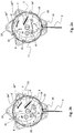
- the shaped element 14 is preferably hinged to the movable element 6 by means of a pin 21, around which it is movable in rotation between a release position, shown in fig. 2a , in which the actuation cable 2 can be unwound and rewound by the winding devices, and a stop position, shown in fig. 2b , in which the shaped element 14 is engaged in one of said recesses 12.
- the shaped element 14 preferably has at least one cavity 8 configured to house a removable mass.
- the cavity 8 is positioned in proximity to the engagement section 15 so as to present a distance from the axis of the pin 21 greater than the distance between the axis of the pin 21 and the housing seat 17.
- the distance of said cavity 8 from the axis of the pin 21 is greater than or equal to 4 mm.
- the blocking assembly comprises a stop element 19 configured to limit the rotation of the shaped element 14 and keep it, jointly with the exerted compression action of the helical spring 13, in the release position.
- the shaped element 14 is advantageously kept in a fixed position during the use of the device, so as to counteract any undesired oscillations of the shaped element itself and therefore make the system more stable.
- the shaped element 14 is in the release position, at a distance from the crown element 11 whose value is greater than 1 mm.
- the shaped element 14 also preferably has a concavity 22 configured to engage said cylindrical pin 5, when the shaped element 14 is in a stop position.
- a concavity 22 configured to engage said cylindrical pin 5, when the shaped element 14 is in a stop position.
- a path is suitably prepared along which the actuation cable 2 is passed starting from the retaining device 7, to which it is fixed by means of an end thereof, up to an outlet section 35 through which it exits from the main body 3 in order to be connected to a suitable connection device 36.
- the first end of the cable 2 is engaged with the retaining device 7, positioned on the second surface of the movable element 6.
- the actuation cable 2 is then passed through a first through-hole 34', towards the first surface of the movable element 6 opposite said second surface, and then wound on the winding surface defined by the first and second supporting elements 23, 31, clockwise and at an angle of about 300°.
- the actuation cable 2 is then passed through a second through-hole 34" towards the second surface and then again inserted into a third through-hole 34'" so as to be re-introduced towards the first surface of the movable element 6 and thus be wound in turns on the winding surface.
- the actuation cable 2 is finally inserted in the outlet section 35 and the second end thereof connected to the connection device 36.
- This preferred path advantageously allows the tensile stress created by the cable to be divided over several sections so that, when the cable reaches the end of its stroke, or the unwinding thereof is interrupted as a result of the activation of the locking system, the tensile force acts mainly on the winding devices and not on the retaining device 7, thus ensuring the maintenance of the constraint between the first end of the actuation cable 2 and the retaining device 7.
- the device 10 advantageously finds multiple possible uses, in particular linked to safety problems or even simply to the need to have a movement stop system which is simple and has a high response speed.
- the device 10 is used in association with a protective garment integrating an airbag system.
- the protective garment houses one or more gas generators (generally in the form of cartridges) which can be activated by means of respective charges, triggered by a rapid extraction of occlusion elements 38, arranged in an inlet section of said gas generators (not shown in the figures).
- the garment therefore has one or more cavities, configured to receive the gas blown at high speed when the airbag system is activated, so as to obtain an appropriate protection of the user with respect to impacts.
- the device 10 is an integral part of the protective garment and is joined to the occlusion elements 38 by means of one or more connectors 39 which extend from the main body 3.
- a user driving a motor vehicle partially unwinds the actuation cable 2 so as to connect the device 10 to the motor vehicle itself by means of the connection device 36.
- the actuation cable is subjected to tensile stress, for example due to movements of the user with respect to the body of the motor vehicle, the centrifugal force tends to rotate the shaped element away from the cylindrical pin 5, but it is kept in the release position by the compression action performed by the helical spring 13.
- the actuation cable 2 can be unwound and rewound by means of the winding devices, in particular thanks to the action carried out by the elastic element 25, allowing both micro-movements and macro-movements of the user while driving the motor vehicle.
- the particular shape of the blocking assembly allows to apply the principle of Euler's critical buckling load to the helical spring 13, allowing to size the device 10 so as to determine the locking of the actuation cable 2 in a simple and safe way, upon the confirmation of a stress deemed abnormal.
- the helical spring 13 initially operates in compression, to keep the shaped element 14 distant from the plurality of recesses 12. Following the effect of a centrifugal force exerted on the shaped element 14, due to an acceleration pulse of rotation or a high rotation speed of the movable element 6, the helical spring 13 flexes according to the principle of overcoming Euler's critical load.
- the helical spring 13 is in fact constrained at the ends thereof respectively in the seat 17 of the shaped element 14 and in the matching element 18 and has a central portion free from constraints.
- a traction acting on the actuation cable 2 exceeds a certain threshold value
- the value of the centrifugal force acting on the shaped element 14 exceeds the value of the compression force exerted by the helical spring 13 thereon, causing a relative compression action which acts on the helical spring 13 on one end thereof until, once the critical load value is exceeded, it causes its immediate failure and therefore deflection in the central portion, which is free from constraints.
- the shaped element 14 is therefore free to rotate to the stop position, where it is engaged with one of the recesses 12 present on the crown element 11, causing the rotation of the movable element 6 to be blocked and consequently to stop the unwinding of the cable 2.
- the particular structure of the device 10 therefore advantageously allows the use of a helical spring 13 which works in compression until reaching Euler's critical buckling load value acting on the helical spring 13 itself.
- the actuation cable 2 connected to the motorcycle by means of the connection device 36, exerts a tensile action on the occlusion element 38 through the relative connector 39, triggering the filler which allows the gas leak from the gas generator and the consequent inflation of the cavity present on the garment.
- the device 10 for controlling the unwinding of an actuation cable of an airbag system can be advantageously customized both on the basis of the type of motor vehicle driven and on the basis of specific needs and/or driving conditions.
- the size of the mass inserted in the cavity 8 depending on the desired level of reactivity with respect to stresses.
- the mass to be used can be chosen, for example, based on the type of driving, i.e., a smaller mass may be provided for the use of the motorcycle at high speeds (e.g., competitions), while it may be of a larger size for use in city or Enduro riding.
- the user can use the same device 10 in various conditions of use, simply by replacing only the shaped element 14 from time to time.
- the relative arrangement between helical spring 13 and shaped element 14 is suitably defined during the design phase, so as to exploit the entire mass of the shaped element 14 to achieve the critical load of the helical spring 13.
Landscapes
- Engineering & Computer Science (AREA)
- Mechanical Engineering (AREA)
- Air Bags (AREA)
Abstract
Description
- The present invention relates to the sector of restraint and activation systems for airbag devices. In particular, the invention relates to a device for controlling the unwinding of an actuation cable of an airbag.
- Airbag jackets are currently available on the market. These are garments which are worn by motorcyclists and which comprise therein an airbag which can be activated through activation devices which can be electronic or mechanical.
- The electronic activation devices use the measurements made by one or more sensors (e.g., accelerometers, proximity sensors, gyroscopes, etc.) to detect the motorcyclist's fall. When this occurs, the activation device activates an airbag filler which opens and protects the motorcyclist during the fall.
- However, the electronic activation devices require a very careful design which allows to distinguish with certainty when a certain acceleration, or a certain separation of the motorcyclist from the saddle, is the result of a fall and not, instead, of the normal use of the vehicle. Furthermore, these devices require being powered, which entails periodic verification and/or replacement of the power supply system.
- An example of these systems is described in
US2007069507 . An electric cable is wound on a reel device fixed to the motorcycle. In the use, the motorcyclist unwinds the cable by pulling a free end of the same cable which then attaches to a filler opening system present in the jacket worn. The reel comprises an electronic detection system which determines the length of the unwound cable and the unwinding speed and acceleration. As a function of the measurements made, the detection system determines whether the motorcyclist has been separated from the vehicle and sends, through the electric cable, a command signal to the jacket which causes the opening of the airbag. This solution is however very bulky and the electric cable, if not well sized, could wear out with use. -
JP5421166B2 - The mechanical actuation devices are generally of simpler construction and provide an actuation cable which, when pulled beyond a certain limit (for example due to a fall of the motorcyclist), activates the airbag filler.
- According to a first solution, the cable is a flexible cable, one end of which is fixed to the airbag filler, and the other end of which is fixed to the vehicle. In case of separation from the vehicle, the cable is pulled and the airbag opens. However effective it may be, this solution requires that the cable extend for the maximum extension thereof to activate the filler, therefore it requires a certain amount of activation time.
- In a second solution described in
EP2576295 , the two ends of the cable are fixed on one side to the vehicle and on the other to a stem which, when subjected to traction, breaks and releases a perforating tip which releases the gas kept pressurized in a special container, thus allowing the inflation of the airbag. However effective it may be, this solution has the limitation that the stem could break for reasons not dependent on the traction of the cable, moreover the intervention time depends on the cable length. - The need for a wearable airbag actuation system is therefore felt (in a jacket for motorcyclists or for operators of other vehicles such as personal watercraft, or for horseback riders on horses), which is quick, reliable and simple to build.
- An object of the present invention is to overcome the disadvantages of the prior art.
- In particular, an object of the present invention is to provide a device for controlling the unwinding of an airbag actuation cable which is simple to manufacture and use, while simultaneously maintaining high reliability over time.
- Another object of the present invention is to provide a device for controlling the unwinding of an actuation cable characterized by a low weight and dimensions, so that it can be placed in association with a protective garment to be worn during the use of a motorized vehicle.
- A further object of the present invention is to provide a device for controlling the unwinding of an actuation cable which is overall inexpensive compared to the devices of the background art.
- Finally, an object of the present invention is to provide a device for controlling the unwinding of an airbag system actuation cable which can be customizable, also as regards the reaction sensitivity to external stresses, both on the basis of the type of motor vehicle driven, and according to specific needs and/or driving conditions.
- These and other objects of the present invention are achieved by a device incorporating the features of the accompanying claims, which form an integral part of the present description.
- According to a first aspect, the present invention relates to a device for controlling the unwinding of an airbag actuation cable, comprising a main body inside which a movable element and a locking system of the movable element are housed. The movable element is rotatably arranged in said main body and comprises winding devices, arranged on a first surface of the movable element itself, and configured to wind and unwind the actuation cable. The movable element also comprises a retaining device arranged on a second surface of the movable element itself and configured to hold an end of the actuation cable. The locking system of the movable element comprises a crown element, integral with the main body and having a profile provided with a plurality of recesses facing a second surface of the movable element, said second surface being arranged at one end of the movable element opposite the first surface. The locking system of the movable element further comprises a blocking assembly, arranged on said second surface and comprising a helical spring which works in compression and which has at least one central portion free from constraints. The blocking assembly further comprises a shaped element, hinged to the movable element, which has an engagement section adapted to engage in said recesses, and a housing seat in which a first end of the helical spring is constrained; the housing seat is arranged such that, during the winding and unwinding of the actuation cable, the thrust of the spring on the seat maintains the engagement section distant from said recesses. The blocking assembly further comprises a matching element in which a second end of the helical spring is constrained.
- According to this solution, a device is obtained, which allows to quickly block the unwinding of the winding cable, if an unexpected event occurs, even before such cable is unwound for the entire length thereof, also improving the response time of the device itself.
- In accordance with a further aspect, the invention relates to a protective garment integrating an airbag system which comprises a device for controlling the unwinding of a cable for the actuation of said airbag system, in which the airbag system is activatable by means of the removal of an occlusion element; the occlusion element is constrained to the device for controlling the unwinding of the actuation cable; the actuation cable is wound in the device for controlling the unwinding and is connected, by means of an end thereof, to a connection device configured to connect the actuation cable to a motor vehicle; the device for controlling the unwinding of the actuation cable is a device according to the present invention.
- According to this solution, the device for controlling the unwinding of the actuation cable according to the invention is an integral part of the protective garment and is joined to the occlusion elements by means of one or more connectors which extend from the main body; an integrated and highly reliable system is thus created in a simple and inexpensive way, comprising both an airbag and the devices for controlling the opening of the same.
- The present invention in at least one of the aforesaid aspects may have at least one of the following preferred features, taken individually or in combination with any other one of the preferred characteristics described.
- Preferably the shaped element is hinged to the movable element by means of a pin, around which it is movable in rotation between a release position, in which the helical spring works in compression and the actuation cable can be unwound and rewound by the winding devices, and a lock position in which, following an acceleration pulse or a high rotation speed of the movable element, the helical spring flexes and the shaped element is engaged in one of said recesses.
- In this way, exploiting the Euler's principle of buckling, the characteristics of the device object of the invention are such that, when the actuation cable is stressed during unwinding by a force greater than a threshold value, the centrifugal force acting on the shaped element causes the rotation around the pin and involves a relative compression action which substantially acts in an axial direction on the helical spring until, after exceeding Euler's critical load value (also called Euler's buckling), it causes the deflection so as to allow the free rotation of the shaped element up to a position in which it is engaged with one of the recesses on the crown element.
- The particular structure of the device therefore advantageously allows the use of a helical spring which works in compression until reaching Euler's critical buckling load value, acting on the helical spring itself.
- In this way, during the normal use of the device, the actuation cable is free to slide, thus allowing ample freedom of movement for the user of the device and, on the other hand, the locking of the unwinding of the cable is advantageously carried out when an abnormal stress occurs.
- Preferably, the shaped element has at least one cavity configured to house a removable mass.
- According to this embodiment, the mass of the shaped element is substantially concentrated in a point, coinciding with the position of the cavity, and therefore allows easier sizing of the elements of the device as well as their mutual position, so as to precisely determine the acting forces during the operation thereof and consequently the reaction times of the device.
- In this way, moreover, it is possible to customize the control device according to the characteristics of use as well as the specific needs of the user, sizing from time to time the measurement of the mass inserted in the cavity, according to the desired level of reactivity with respect to stresses.
- Preferably said cavity is positioned in proximity to said engagement section so as to present a distance from the axis of the pin which is greater than the distance between the axis of the pin and the housing seat.
- According to such configuration, it is possible to improve the efficiency of the response to the stresses acting on the control device, since the compression action generated by the shaped element on the helical spring can exploit a longer arm (given by the distance of the cavity hosting the removable mass with respect to the centre of rotation coinciding with the centre of symmetry of the pin) with respect to the arm exploited by the compression action provided by the helical spring on the shaped element.
- Preferably, said blocking assembly comprises a stop element configured to limit the rotation of the shaped element and keep it, jointly with the exerted compression action of the helical spring, in the release position.
- In this way, the shaped element is advantageously kept in a fixed position so as to avoid undesired oscillations of the shaped element itself, during the use of the device and therefore making the system more stable.
- Preferably the main body comprises a base element and a covering element configured to be mutually connected in a removable manner, the base element having a base surface from which extends a cylindrical pin on which the movable element is arranged, rotatable with respect to the axis of said cylindrical pin.
- In this way, a protection structure is created for the control device, which also allows a functional access to the components contained therein for any replacement or modification thereof.
- Preferably the shaped element comprises a concavity configured to engage said cylindrical pin, when the shaped element is in the lock position.
- In this way, also in this position an element to contain the movement of the shaped element is obtained, allowing to increase the stability of the device with respect to external stresses.
- Preferably, the winding devices comprise a first supporting element, of a substantially annular shape and extending from the first surface of the movable element, configured to support the actuation cable during winding.
- Preferably, the winding devices comprise an abutment disk configured to be associated with the movable element so as to make it integral with the rotary movement of the movable element around the axis of the cylindrical pin and to define, jointly with said movable element and with said first supporting element, a housing volume for an elastic return element.
- According to this configuration, the elements arranged for unwinding/rewinding the actuation cable are advantageously grouped in a "spool" system, which is separate from the locking system and therefore does not interfere with the correct functioning thereof; this "spool" system is furthermore advantageously compact and easily configurable on the basis of the size of the actuation cable used and/or of the additional elements which form the control device.
- Preferably, during the unwinding and rewinding of the actuation cable, the shaped element is in the release position, at a distance from the crown element whose value is greater than 1 mm.
- According to this configuration, an easy rotation of the shaped element integral with the rotation movement of the movable element is ensured, ensuring the absence of mutual interference of the movable parts of the device during the unwinding and rewinding of the actuation cable, during the use thereof.
- Further features and advantages of the present invention will be more apparent from the description of the accompanying drawings.
- The invention will be described below with reference to some examples, provided for explanatory and non-limiting purposes, and illustrated in the accompanying drawings. These drawings illustrate different aspects and embodiments of the present invention and, where appropriate, reference numerals illustrating similar structures, components, materials and/or elements in different figures are indicated by similar reference numbers.
-
Figure 1 shows an overall schematic front view of a device for controlling the unwinding of an actuation cable of an airbag according to an embodiment of the present invention; -
figures 2a and 2b show a schematic front view of an assembly belonging to the device offigure 1 in respective operating configurations -
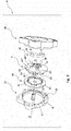
figure 3 illustrates an exploded view of the device offigure 1 in a first perspective view, with some parts removed to better highlight others; -
figure 4 illustrates an exploded view of the device offigure 1 in a second perspective view, with some parts removed to better highlight others; and -
figure 5 is a schematic front view of an element of the assembly offigures 2a and 2b . - While the invention is susceptible to various modifications and alternative constructions, certain preferred embodiments are shown in the drawings and are described hereinbelow in detail. It is in any case to be noted that there is no intention to limit the invention to the specific embodiment illustrated, rather on the contrary, the invention intends covering all the modifications, alternative and equivalent constructions that fall within the scope of the invention as defined in the claims.
- The use of "for example", "etc.", "or" indicates non-exclusive alternatives without limitation, unless otherwise indicated. The use of "includes" means "includes, but not limited to", unless otherwise indicated.
- With reference to
Figures 1-5 , a device for controlling the unwinding of an airbag actuation cable according to the present invention is illustrated. - With reference to
figure 1 , thereference number 10 generally indicates a device for controlling the unwinding of an actuation cable, in accordance with the present invention. - The
device 10 has amain body 3 which comprises abase element 27 and acovering element 28 configured to be mutually connected preferably in a removable manner, for example by means of a threaded connection and/or hooking means. - The
base element 27 has a substantially planar and preferablycircular base surface 4, from the centre of which extends acylindrical pin 5 having a longitudinal axis "X-X" perpendicular to saidbase surface 4. - The
device 10 further comprises amovable element 6, connected to thecylindrical pin 5 by means of a through-hole 9 obtained in a central position of themovable element 6, which is movable in rotation about the axis "X-X" of thecylindrical pin 5. - The
movable element 6 comprises winding devices arranged on a first surface of the element itself, which are configured to wind and unwind theactuation cable 2 during the operation of thedevice 10. In particular, as shown infigures 3 ,4 and5 , these winding devices comprise a first supportingelement 23, having a substantially annular shape which extends from a first surface of themovable element 6, and is configured to support theactuation cable 2 during winding. - The winding devices further comprise an
complementary disk 26 comprising a second supportingelement 31 of substantially annular shape, which extends from thecomplementary disk 26 facing the first supportingelement 23, and configured to support theactuation cable 2 during winding. - Preferably, the first supporting
element 23 has a plurality ofengagement elements 32 configured to be associated withcorresponding housings 33 present in saidcomplementary disk 26, so as to make themovable element 6 integral with thecomplementary disk 26 itself. In the assembled configuration of themovable element 6 with thecomplementary disk 26, the first supportingelement 23 and the second supportingelement 31 are brought into contact, obtaining a substantially planar and continuous winding surface, on which theactuation cable 2 is wound. - Preferably, said winding surface is arranged substantially perpendicular to the first surface of the
movable element 6 and has a width greater than or equal to 4 mm and less than or equal to 10 mm. In this way, theactuation cable 2 can be easily wound and unwound thereon, avoiding deformations of the same. - The first supporting
element 23 and the second supportingelement 31 also define ahousing volume 24 in which anelastic element 25 is positioned. Preferably, thiselastic element 25 is formed by a flat or ribbon spiral spring, which is constrained to themovable element 6 by means of a first end portion, for example shaped according to aring 29. Preferably thering 29 is obtained by folding a free end of the spiral spring and is connected to one of theengagement elements 32 obtained along the annular extension of the first supportingelement 23. Theelastic element 25 is also connected to thecylindrical pin 5 by means of a second end portion, preferably engaged in agroove 37 present on thecylindrical pin 5 itself. - Therefore, a simple and compact "spool" structure is advantageously created, for a correct and efficient unwinding and rewinding of the
actuation cable 2. This spool structure is also easily configurable on the basis of the size and length of theactuation cable 2 used, thus making thedevice 10 versatile in that it makes it possible to use it in a differentiated way according to the specific needs of the end user. - The
device 10 also has a locking system for themovable element 6, comprising acrown element 11 and a blocking assembly adapted to allow stopping the unwinding movement of the actuation cable, induced by the interruption of the rotary movement of themovable element 6. - The
crown element 11 is preferably integral with themain body 3, in particular being obtained in the coveringelement 28, and has a profile provided with a plurality ofrecesses 12 facing towards themovable element 6. In a preferred configuration, the plurality ofrecesses 12 faces a second surface of saidmovable element 6, opposite said first surface. Preferably the crown element has a sawtooth profile which defines a succession of alternating protrusions and indentations which form the aforementioned recesses 12. - The blocking assembly is preferably arranged on said second surface of the
movable element 6 and comprises ahelical spring 13, which works in compression and which has at least a central portion free from constraints. - The blocking assembly further comprises a shaped
element 14 hinged to themovable element 6, and which comprises anengagement section 15, adapted to engage saidrecesses 12 and ahousing seat 17 in which a first end of thehelical spring 13 is constrained. In the blocking assembly a matchingelement 18 is also provided in which a second end of thehelical spring 13 and aretaining device 7 are constrained, adapted to hold an end of theactuation cable 2. - Said retaining
device 7 can be formed by a guide having open ends, so as to allow the passage of theactuation cable 2, and preferably having mutually facing inner walls having a surface such as to disadvantage any sliding movements of theactuation cable 2; such surfaces can for example be formed by knurled and/or notched surfaces and/or having adhesiveness characteristics. Theactuation cable 2 can have an enlargement at an end portion thereof, which is placed outside the aforementioned guide, allowing further improvement of the stability of the anchoring of theactuation cable 2 to theretaining device 7 itself. - The shaped
element 14 is preferably hinged to themovable element 6 by means of apin 21, around which it is movable in rotation between a release position, shown infig. 2a , in which theactuation cable 2 can be unwound and rewound by the winding devices, and a stop position, shown infig. 2b , in which the shapedelement 14 is engaged in one of said recesses 12. - The shaped
element 14 preferably has at least onecavity 8 configured to house a removable mass. Preferably thecavity 8 is positioned in proximity to theengagement section 15 so as to present a distance from the axis of thepin 21 greater than the distance between the axis of thepin 21 and thehousing seat 17. Preferably the distance of saidcavity 8 from the axis of thepin 21 is greater than or equal to 4 mm. - Preferably the blocking assembly comprises a
stop element 19 configured to limit the rotation of the shapedelement 14 and keep it, jointly with the exerted compression action of thehelical spring 13, in the release position. In this way, the shapedelement 14 is advantageously kept in a fixed position during the use of the device, so as to counteract any undesired oscillations of the shaped element itself and therefore make the system more stable. - Preferably, during the unwinding and rewinding of the
actuation cable 2, the shapedelement 14 is in the release position, at a distance from thecrown element 11 whose value is greater than 1 mm. - The shaped
element 14 also preferably has aconcavity 22 configured to engage saidcylindrical pin 5, when the shapedelement 14 is in a stop position. In this way, an element for containing the movement of the shaped element can advantageously be provided, allowing to increase the stability of the device with respect to external stresses during the operation thereof. - In an assembly step prior to the use of the
device 10, a path is suitably prepared along which theactuation cable 2 is passed starting from the retainingdevice 7, to which it is fixed by means of an end thereof, up to anoutlet section 35 through which it exits from themain body 3 in order to be connected to asuitable connection device 36. - According to a preferred embodiment, the first end of the
cable 2 is engaged with the retainingdevice 7, positioned on the second surface of themovable element 6. Theactuation cable 2 is then passed through a first through-hole 34', towards the first surface of themovable element 6 opposite said second surface, and then wound on the winding surface defined by the first and second supportingelements actuation cable 2 is then passed through a second through-hole 34" towards the second surface and then again inserted into a third through-hole 34'" so as to be re-introduced towards the first surface of themovable element 6 and thus be wound in turns on the winding surface. Theactuation cable 2 is finally inserted in theoutlet section 35 and the second end thereof connected to theconnection device 36. - This preferred path advantageously allows the tensile stress created by the cable to be divided over several sections so that, when the cable reaches the end of its stroke, or the unwinding thereof is interrupted as a result of the activation of the locking system, the tensile force acts mainly on the winding devices and not on the
retaining device 7, thus ensuring the maintenance of the constraint between the first end of theactuation cable 2 and the retainingdevice 7. - The
device 10 advantageously finds multiple possible uses, in particular linked to safety problems or even simply to the need to have a movement stop system which is simple and has a high response speed. - In particular, in a preferred form of use, the
device 10 is used in association with a protective garment integrating an airbag system. According to this use, the protective garment houses one or more gas generators (generally in the form of cartridges) which can be activated by means of respective charges, triggered by a rapid extraction ofocclusion elements 38, arranged in an inlet section of said gas generators (not shown in the figures). The garment therefore has one or more cavities, configured to receive the gas blown at high speed when the airbag system is activated, so as to obtain an appropriate protection of the user with respect to impacts. According to the invention, thedevice 10 is an integral part of the protective garment and is joined to theocclusion elements 38 by means of one ormore connectors 39 which extend from themain body 3. - In the use of the
device 10, a user driving a motor vehicle partially unwinds theactuation cable 2 so as to connect thedevice 10 to the motor vehicle itself by means of theconnection device 36. When the actuation cable is subjected to tensile stress, for example due to movements of the user with respect to the body of the motor vehicle, the centrifugal force tends to rotate the shaped element away from thecylindrical pin 5, but it is kept in the release position by the compression action performed by thehelical spring 13. In this way, theactuation cable 2 can be unwound and rewound by means of the winding devices, in particular thanks to the action carried out by theelastic element 25, allowing both micro-movements and macro-movements of the user while driving the motor vehicle. - The particular shape of the blocking assembly allows to apply the principle of Euler's critical buckling load to the
helical spring 13, allowing to size thedevice 10 so as to determine the locking of theactuation cable 2 in a simple and safe way, upon the confirmation of a stress deemed abnormal. In fact, thehelical spring 13 initially operates in compression, to keep theshaped element 14 distant from the plurality ofrecesses 12. Following the effect of a centrifugal force exerted on the shapedelement 14, due to an acceleration pulse of rotation or a high rotation speed of themovable element 6, thehelical spring 13 flexes according to the principle of overcoming Euler's critical load. - More particularly, the
helical spring 13 is in fact constrained at the ends thereof respectively in theseat 17 of the shapedelement 14 and in the matchingelement 18 and has a central portion free from constraints. When a traction acting on theactuation cable 2 exceeds a certain threshold value, the value of the centrifugal force acting on the shapedelement 14 exceeds the value of the compression force exerted by thehelical spring 13 thereon, causing a relative compression action which acts on thehelical spring 13 on one end thereof until, once the critical load value is exceeded, it causes its immediate failure and therefore deflection in the central portion, which is free from constraints. The shapedelement 14 is therefore free to rotate to the stop position, where it is engaged with one of therecesses 12 present on thecrown element 11, causing the rotation of themovable element 6 to be blocked and consequently to stop the unwinding of thecable 2. The particular structure of thedevice 10 therefore advantageously allows the use of ahelical spring 13 which works in compression until reaching Euler's critical buckling load value acting on thehelical spring 13 itself. - Upon reaching this stop position, therefore, the
actuation cable 2, connected to the motorcycle by means of theconnection device 36, exerts a tensile action on theocclusion element 38 through therelative connector 39, triggering the filler which allows the gas leak from the gas generator and the consequent inflation of the cavity present on the garment. - The
device 10 for controlling the unwinding of an actuation cable of an airbag system can be advantageously customized both on the basis of the type of motor vehicle driven and on the basis of specific needs and/or driving conditions. - In particular, it is possible to suitably choose the size of the mass inserted in the
cavity 8, depending on the desired level of reactivity with respect to stresses. For example, it is possible to provide shapedelements 14, having the same structure and dimensions, but differentiated according to the size of thecavity 8, so as to accommodate masses of different sizes. The mass to be used can be chosen, for example, based on the type of driving, i.e., a smaller mass may be provided for the use of the motorcycle at high speeds (e.g., competitions), while it may be of a larger size for use in city or Enduro riding. According to this sizing possibility, the user can use thesame device 10 in various conditions of use, simply by replacing only the shapedelement 14 from time to time. - However, other possible configurations of the
device 10 are not excluded, such as for example shapedelements 14 of different sizes and shapes, not havingcavities 8 for housing a mass. According to this possible variant, the relative arrangement betweenhelical spring 13 and shapedelement 14 is suitably defined during the design phase, so as to exploit the entire mass of the shapedelement 14 to achieve the critical load of thehelical spring 13.
Claims (11)
- Device (10) for controlling the unwinding of an actuation cable (2) of an airbag, comprising a main body (3) inside which a movable element (6) and a locking system of the movable element (6) are housed, wherein- the movable element (6) is arranged rotatable in said main body (3) and comprises:- winding devices, arranged on a first surface of said movable element (6), and configured to wind and unwind the actuation cable (2); and- a retaining device (7) arranged on a second surface of said movable element (6) and configured to hold an end of the actuation cable (2); and wherein- the locking system of the movable element (6) comprises:and wherein said blocking assembly comprises:- a crown element (11) integral with the main body (3) and having a profile provided with a plurality of recesses (12) facing a second surface of said movable element (6), said second surface being arranged at an end of the movable element opposite the first surface; and- a blocking assembly, arranged on said second surface of the movable element (6);- a helical spring (13) which works in compression and has at least one central portion free from constraints;- a shaped element (14) hinged to the movable element (6), said shaped element (14) comprising an engagement section (15), adapted to engage in said recesses (12), and a housing seat (17) in which a first end of the helical spring (13) is constrained, the housing seat (17) being arranged such that, during the winding and unwinding of the actuation cable (2), the thrust of the spring on the seat (17) maintains the engagement section (15) distant from said recesses (12);- a matching element (18) in which a second end of the helical spring (13) is constrained.
- Device (10) according to claim 1, wherein said shaped element (14) is hinged to the movable element (6) by means of a pin (21), around which it is movable in rotation between a release position, in which the helical spring (13) works in compression and the actuation cable (2) can be unwound and rewound by the winding devices, and a lock position in which, following an acceleration pulse or a high rotation speed of the movable element (6), the helical spring (13) flexes and the shaped element (14) is engaged in one of said recesses (12).
- Device (10) according to claim 1 or 2, wherein said shaped element (14) has at least one cavity (8) configured to house a removable mass.
- Device (10) according to claim 3, wherein said cavity (8) is positioned in proximity to said engagement section (15) so as to present a distance from the axis of the pin (21), greater than the distance between the axis of the pin (21) and the housing seat (17).
- Device (10) according to any one of claims 2 to 4, wherein said blocking assembly comprises a stop element (19) configured to limit the rotation of the shaped element (14) and keep it, jointly with the exerted compression action of the helical spring (13), in the release position.
- Device (10) according to claim 1, wherein the main body (3) comprises a base element (27) and a covering element (28) configured to be mutually connected in a removable manner, the base element (27) having a base surface (4) from which extends a cylindrical pin (5) on which the movable element (6) is arranged rotatable with respect to the axis of said cylindrical pin (5).
- Device (10) according to any one of claims 2 to 6, wherein the shaped element (14) comprises a concavity (22) configured to engage said cylindrical pin (5) when the shaped element (14) is in the lock position.
- Device (10) according to claim 1, wherein said winding devices comprise a first supporting element (23), of a substantially annular shape and extending from the first surface of the movable element (6), configured to support the actuation cable (2) during winding.
- Device (10) according to claim 8, wherein said winding devices comprise a complementary disk (26) configured to be associated with the movable element (6) so as to make it integral with the rotary movement of the movable element (6) around the axis of the cylindrical pin (5) and to define, jointly with said movable element (6) and with said first supporting element (23), a housing volume (24) for an elastic element (25).
- Device (10) according to any one of claims from 2 to 9, wherein during the unwinding and rewinding of the actuation cable (2), the shaped element (14) is in the release position, at a distance from the crown element (11) whose value is greater than 1 mm.
- Protective garment integrating an airbag system and comprising a device for controlling the unwinding of a cable (2) for the actuation of said airbag system, said airbag system being activatable by means of the removal of an occlusion element (38); wherein
the occlusion element (38) is constrained to the device for controlling the unwinding of the actuation cable (2) and the actuation cable (2) is wound in the device for controlling the unwinding and is connected, by means of an end thereof, to a connection device (36) configured to connect the actuation cable (2) to a motor vehicle; and wherein
the device for controlling the unwinding of the actuation cable (2) is a device (10) according to one or more of the claims from 1 to 10.
Applications Claiming Priority (1)
| Application Number | Priority Date | Filing Date | Title |
|---|---|---|---|
| IT102019000010314A IT201900010314A1 (en) | 2019-06-27 | 2019-06-27 | DEVICE FOR THE CONTROL OF THE UNWINDING OF AN AIRBAG DRIVING CABLE |
Publications (2)
| Publication Number | Publication Date |
|---|---|
| EP3756494A1 true EP3756494A1 (en) | 2020-12-30 |
| EP3756494B1 EP3756494B1 (en) | 2023-08-16 |
Family
ID=68343283
Family Applications (1)
| Application Number | Title | Priority Date | Filing Date |
|---|---|---|---|
| EP20182670.8A Active EP3756494B1 (en) | 2019-06-27 | 2020-06-26 | Device for controlling the unwinding of an airbag actuation cable |
Country Status (2)
| Country | Link |
|---|---|
| EP (1) | EP3756494B1 (en) |
| IT (1) | IT201900010314A1 (en) |
Citations (5)
| Publication number | Priority date | Publication date | Assignee | Title |
|---|---|---|---|---|
| JPS5421166B2 (en) | 1974-09-04 | 1979-07-28 | ||
| WO2004092000A1 (en) * | 2003-04-16 | 2004-10-28 | Bayerische Motoren Werke Aktiengesellschaft | Motorcycle comprising a restraining device |
| EP1668999A1 (en) * | 2004-12-10 | 2006-06-14 | Honda Motor Co., Ltd. | Airbag apparatus for a vehicle passenger |
| US20070069507A1 (en) | 2005-09-14 | 2007-03-29 | Honda Motor Co., Ltd. | Rider separation detecting device |
| EP2576295A1 (en) | 2010-05-28 | 2013-04-10 | Helite S.a.r.l. | Device for inflating airbag |
-
2019
- 2019-06-27 IT IT102019000010314A patent/IT201900010314A1/en unknown
-
2020
- 2020-06-26 EP EP20182670.8A patent/EP3756494B1/en active Active
Patent Citations (5)
| Publication number | Priority date | Publication date | Assignee | Title |
|---|---|---|---|---|
| JPS5421166B2 (en) | 1974-09-04 | 1979-07-28 | ||
| WO2004092000A1 (en) * | 2003-04-16 | 2004-10-28 | Bayerische Motoren Werke Aktiengesellschaft | Motorcycle comprising a restraining device |
| EP1668999A1 (en) * | 2004-12-10 | 2006-06-14 | Honda Motor Co., Ltd. | Airbag apparatus for a vehicle passenger |
| US20070069507A1 (en) | 2005-09-14 | 2007-03-29 | Honda Motor Co., Ltd. | Rider separation detecting device |
| EP2576295A1 (en) | 2010-05-28 | 2013-04-10 | Helite S.a.r.l. | Device for inflating airbag |
Also Published As
| Publication number | Publication date |
|---|---|
| IT201900010314A1 (en) | 2020-12-27 |
| EP3756494B1 (en) | 2023-08-16 |
Similar Documents
| Publication | Publication Date | Title |
|---|---|---|
| EP2726157B1 (en) | Fall arrester | |
| US4955638A (en) | Deceleration sensor having safety catch means | |
| US7631830B2 (en) | Retractor with rotary rack pretensioner | |
| JP5587142B2 (en) | Webbing take-up device | |
| EP3756494B1 (en) | Device for controlling the unwinding of an airbag actuation cable | |
| JP6240575B2 (en) | Webbing take-up device | |
| EP4357205A1 (en) | Vehicle sensor device and seat belt retractor employing same | |
| EP0600689B1 (en) | Seat belt retractor with pre-tensioner | |
| US20220273067A1 (en) | Emergency protective helmet | |
| KR101477794B1 (en) | Safety device for seat belt | |
| US5489072A (en) | Seat belt retractor with pre-tensioner | |
| KR102024048B1 (en) | Seatbelt retractor with moving vehicel sensor | |
| KR101165994B1 (en) | Retractor and seat belt therewith | |
| US12486009B2 (en) | Interface device for an inflatable individual safety device | |
| KR100614734B1 (en) | Seat belt retractor | |
| JP5990481B2 (en) | Webbing take-up device | |
| US6343760B1 (en) | Webbing sensor | |
| CN113518736B (en) | Seat belt retractor with auxiliary spool locking system | |
| KR20130012694A (en) | Retractor and seat belt therewith | |
| KR101256214B1 (en) | Safety belt that have body protection function | |
| WO2000009367A2 (en) | A triggering means for a safety belt having a pre-tensioning device | |
| ES2277204T3 (en) | NOISE REDUCING DEVICE. | |
| KR200311484Y1 (en) | A buffer protective clothes used compressed gas | |
| KR101276354B1 (en) | Retractor and seat belt therewith | |
| KR100468925B1 (en) | Pretensioner of seat belt retractor |
Legal Events
| Date | Code | Title | Description |
|---|---|---|---|
| PUAI | Public reference made under article 153(3) epc to a published international application that has entered the european phase |
Free format text: ORIGINAL CODE: 0009012 |
|
| STAA | Information on the status of an ep patent application or granted ep patent |
Free format text: STATUS: THE APPLICATION HAS BEEN PUBLISHED |
|
| AK | Designated contracting states |
Kind code of ref document: A1 Designated state(s): AL AT BE BG CH CY CZ DE DK EE ES FI FR GB GR HR HU IE IS IT LI LT LU LV MC MK MT NL NO PL PT RO RS SE SI SK SM TR |
|
| AX | Request for extension of the european patent |
Extension state: BA ME |
|
| STAA | Information on the status of an ep patent application or granted ep patent |
Free format text: STATUS: REQUEST FOR EXAMINATION WAS MADE |
|
| 17P | Request for examination filed |
Effective date: 20210617 |
|
| RBV | Designated contracting states (corrected) |
Designated state(s): AL AT BE BG CH CY CZ DE DK EE ES FI FR GB GR HR HU IE IS IT LI LT LU LV MC MK MT NL NO PL PT RO RS SE SI SK SM TR |
|
| GRAP | Despatch of communication of intention to grant a patent |
Free format text: ORIGINAL CODE: EPIDOSNIGR1 |
|
| STAA | Information on the status of an ep patent application or granted ep patent |
Free format text: STATUS: GRANT OF PATENT IS INTENDED |
|
| INTG | Intention to grant announced |
Effective date: 20230403 |
|
| GRAS | Grant fee paid |
Free format text: ORIGINAL CODE: EPIDOSNIGR3 |
|
| GRAA | (expected) grant |
Free format text: ORIGINAL CODE: 0009210 |
|
| STAA | Information on the status of an ep patent application or granted ep patent |
Free format text: STATUS: THE PATENT HAS BEEN GRANTED |
|
| AK | Designated contracting states |
Kind code of ref document: B1 Designated state(s): AL AT BE BG CH CY CZ DE DK EE ES FI FR GB GR HR HU IE IS IT LI LT LU LV MC MK MT NL NO PL PT RO RS SE SI SK SM TR |
|
| P01 | Opt-out of the competence of the unified patent court (upc) registered |
Effective date: 20230725 |
|
| REG | Reference to a national code |
Ref country code: CH Ref legal event code: EP Ref country code: DE Ref legal event code: R096 Ref document number: 602020015716 Country of ref document: DE |
|
| REG | Reference to a national code |
Ref country code: IE Ref legal event code: FG4D |
|
| REG | Reference to a national code |
Ref country code: LT Ref legal event code: MG9D |
|
| REG | Reference to a national code |
Ref country code: NL Ref legal event code: MP Effective date: 20230816 |
|
| REG | Reference to a national code |
Ref country code: AT Ref legal event code: MK05 Ref document number: 1599118 Country of ref document: AT Kind code of ref document: T Effective date: 20230816 |
|
| PG25 | Lapsed in a contracting state [announced via postgrant information from national office to epo] |
Ref country code: GR Free format text: LAPSE BECAUSE OF FAILURE TO SUBMIT A TRANSLATION OF THE DESCRIPTION OR TO PAY THE FEE WITHIN THE PRESCRIBED TIME-LIMIT Effective date: 20231117 |
|
| PG25 | Lapsed in a contracting state [announced via postgrant information from national office to epo] |
Ref country code: IS Free format text: LAPSE BECAUSE OF FAILURE TO SUBMIT A TRANSLATION OF THE DESCRIPTION OR TO PAY THE FEE WITHIN THE PRESCRIBED TIME-LIMIT Effective date: 20231216 |
|
| PG25 | Lapsed in a contracting state [announced via postgrant information from national office to epo] |
Ref country code: SE Free format text: LAPSE BECAUSE OF FAILURE TO SUBMIT A TRANSLATION OF THE DESCRIPTION OR TO PAY THE FEE WITHIN THE PRESCRIBED TIME-LIMIT Effective date: 20230816 Ref country code: RS Free format text: LAPSE BECAUSE OF FAILURE TO SUBMIT A TRANSLATION OF THE DESCRIPTION OR TO PAY THE FEE WITHIN THE PRESCRIBED TIME-LIMIT Effective date: 20230816 Ref country code: PT Free format text: LAPSE BECAUSE OF FAILURE TO SUBMIT A TRANSLATION OF THE DESCRIPTION OR TO PAY THE FEE WITHIN THE PRESCRIBED TIME-LIMIT Effective date: 20231218 Ref country code: NO Free format text: LAPSE BECAUSE OF FAILURE TO SUBMIT A TRANSLATION OF THE DESCRIPTION OR TO PAY THE FEE WITHIN THE PRESCRIBED TIME-LIMIT Effective date: 20231116 Ref country code: NL Free format text: LAPSE BECAUSE OF FAILURE TO SUBMIT A TRANSLATION OF THE DESCRIPTION OR TO PAY THE FEE WITHIN THE PRESCRIBED TIME-LIMIT Effective date: 20230816 Ref country code: LV Free format text: LAPSE BECAUSE OF FAILURE TO SUBMIT A TRANSLATION OF THE DESCRIPTION OR TO PAY THE FEE WITHIN THE PRESCRIBED TIME-LIMIT Effective date: 20230816 Ref country code: LT Free format text: LAPSE BECAUSE OF FAILURE TO SUBMIT A TRANSLATION OF THE DESCRIPTION OR TO PAY THE FEE WITHIN THE PRESCRIBED TIME-LIMIT Effective date: 20230816 Ref country code: IS Free format text: LAPSE BECAUSE OF FAILURE TO SUBMIT A TRANSLATION OF THE DESCRIPTION OR TO PAY THE FEE WITHIN THE PRESCRIBED TIME-LIMIT Effective date: 20231216 Ref country code: HR Free format text: LAPSE BECAUSE OF FAILURE TO SUBMIT A TRANSLATION OF THE DESCRIPTION OR TO PAY THE FEE WITHIN THE PRESCRIBED TIME-LIMIT Effective date: 20230816 Ref country code: GR Free format text: LAPSE BECAUSE OF FAILURE TO SUBMIT A TRANSLATION OF THE DESCRIPTION OR TO PAY THE FEE WITHIN THE PRESCRIBED TIME-LIMIT Effective date: 20231117 Ref country code: FI Free format text: LAPSE BECAUSE OF FAILURE TO SUBMIT A TRANSLATION OF THE DESCRIPTION OR TO PAY THE FEE WITHIN THE PRESCRIBED TIME-LIMIT Effective date: 20230816 Ref country code: AT Free format text: LAPSE BECAUSE OF FAILURE TO SUBMIT A TRANSLATION OF THE DESCRIPTION OR TO PAY THE FEE WITHIN THE PRESCRIBED TIME-LIMIT Effective date: 20230816 |
|
| PG25 | Lapsed in a contracting state [announced via postgrant information from national office to epo] |
Ref country code: PL Free format text: LAPSE BECAUSE OF FAILURE TO SUBMIT A TRANSLATION OF THE DESCRIPTION OR TO PAY THE FEE WITHIN THE PRESCRIBED TIME-LIMIT Effective date: 20230816 |
|
| PG25 | Lapsed in a contracting state [announced via postgrant information from national office to epo] |
Ref country code: ES Free format text: LAPSE BECAUSE OF FAILURE TO SUBMIT A TRANSLATION OF THE DESCRIPTION OR TO PAY THE FEE WITHIN THE PRESCRIBED TIME-LIMIT Effective date: 20230816 |
|
| PG25 | Lapsed in a contracting state [announced via postgrant information from national office to epo] |
Ref country code: SM Free format text: LAPSE BECAUSE OF FAILURE TO SUBMIT A TRANSLATION OF THE DESCRIPTION OR TO PAY THE FEE WITHIN THE PRESCRIBED TIME-LIMIT Effective date: 20230816 Ref country code: RO Free format text: LAPSE BECAUSE OF FAILURE TO SUBMIT A TRANSLATION OF THE DESCRIPTION OR TO PAY THE FEE WITHIN THE PRESCRIBED TIME-LIMIT Effective date: 20230816 Ref country code: ES Free format text: LAPSE BECAUSE OF FAILURE TO SUBMIT A TRANSLATION OF THE DESCRIPTION OR TO PAY THE FEE WITHIN THE PRESCRIBED TIME-LIMIT Effective date: 20230816 Ref country code: EE Free format text: LAPSE BECAUSE OF FAILURE TO SUBMIT A TRANSLATION OF THE DESCRIPTION OR TO PAY THE FEE WITHIN THE PRESCRIBED TIME-LIMIT Effective date: 20230816 Ref country code: DK Free format text: LAPSE BECAUSE OF FAILURE TO SUBMIT A TRANSLATION OF THE DESCRIPTION OR TO PAY THE FEE WITHIN THE PRESCRIBED TIME-LIMIT Effective date: 20230816 Ref country code: CZ Free format text: LAPSE BECAUSE OF FAILURE TO SUBMIT A TRANSLATION OF THE DESCRIPTION OR TO PAY THE FEE WITHIN THE PRESCRIBED TIME-LIMIT Effective date: 20230816 Ref country code: SK Free format text: LAPSE BECAUSE OF FAILURE TO SUBMIT A TRANSLATION OF THE DESCRIPTION OR TO PAY THE FEE WITHIN THE PRESCRIBED TIME-LIMIT Effective date: 20230816 |
|
| REG | Reference to a national code |
Ref country code: DE Ref legal event code: R097 Ref document number: 602020015716 Country of ref document: DE |
|
| PLBE | No opposition filed within time limit |
Free format text: ORIGINAL CODE: 0009261 |
|
| STAA | Information on the status of an ep patent application or granted ep patent |
Free format text: STATUS: NO OPPOSITION FILED WITHIN TIME LIMIT |
|
| 26N | No opposition filed |
Effective date: 20240517 |
|
| PG25 | Lapsed in a contracting state [announced via postgrant information from national office to epo] |
Ref country code: SI Free format text: LAPSE BECAUSE OF FAILURE TO SUBMIT A TRANSLATION OF THE DESCRIPTION OR TO PAY THE FEE WITHIN THE PRESCRIBED TIME-LIMIT Effective date: 20230816 |
|
| PG25 | Lapsed in a contracting state [announced via postgrant information from national office to epo] |
Ref country code: BG Free format text: LAPSE BECAUSE OF FAILURE TO SUBMIT A TRANSLATION OF THE DESCRIPTION OR TO PAY THE FEE WITHIN THE PRESCRIBED TIME-LIMIT Effective date: 20230816 |
|
| PG25 | Lapsed in a contracting state [announced via postgrant information from national office to epo] |
Ref country code: BG Free format text: LAPSE BECAUSE OF FAILURE TO SUBMIT A TRANSLATION OF THE DESCRIPTION OR TO PAY THE FEE WITHIN THE PRESCRIBED TIME-LIMIT Effective date: 20230816 |
|
| PG25 | Lapsed in a contracting state [announced via postgrant information from national office to epo] |
Ref country code: MC Free format text: LAPSE BECAUSE OF FAILURE TO SUBMIT A TRANSLATION OF THE DESCRIPTION OR TO PAY THE FEE WITHIN THE PRESCRIBED TIME-LIMIT Effective date: 20230816 |
|
| REG | Reference to a national code |
Ref country code: CH Ref legal event code: PL |
|
| PG25 | Lapsed in a contracting state [announced via postgrant information from national office to epo] |
Ref country code: LU Free format text: LAPSE BECAUSE OF NON-PAYMENT OF DUE FEES Effective date: 20240626 |
|
| GBPC | Gb: european patent ceased through non-payment of renewal fee |
Effective date: 20240626 |
|
| PG25 | Lapsed in a contracting state [announced via postgrant information from national office to epo] |
Ref country code: IE Free format text: LAPSE BECAUSE OF NON-PAYMENT OF DUE FEES Effective date: 20240626 |
|
| PG25 | Lapsed in a contracting state [announced via postgrant information from national office to epo] |
Ref country code: CH Free format text: LAPSE BECAUSE OF NON-PAYMENT OF DUE FEES Effective date: 20240630 Ref country code: BE Free format text: LAPSE BECAUSE OF NON-PAYMENT OF DUE FEES Effective date: 20240630 |
|
| PG25 | Lapsed in a contracting state [announced via postgrant information from national office to epo] |
Ref country code: GB Free format text: LAPSE BECAUSE OF NON-PAYMENT OF DUE FEES Effective date: 20240626 |
|
| REG | Reference to a national code |
Ref country code: BE Ref legal event code: MM Effective date: 20240630 |
|
| PGFP | Annual fee paid to national office [announced via postgrant information from national office to epo] |
Ref country code: DE Payment date: 20250630 Year of fee payment: 6 |
|
| PGFP | Annual fee paid to national office [announced via postgrant information from national office to epo] |
Ref country code: FR Payment date: 20250624 Year of fee payment: 6 |
|
| PGFP | Annual fee paid to national office [announced via postgrant information from national office to epo] |
Ref country code: IT Payment date: 20250627 Year of fee payment: 6 |
|
| PG25 | Lapsed in a contracting state [announced via postgrant information from national office to epo] |
Ref country code: CY Free format text: LAPSE BECAUSE OF FAILURE TO SUBMIT A TRANSLATION OF THE DESCRIPTION OR TO PAY THE FEE WITHIN THE PRESCRIBED TIME-LIMIT; INVALID AB INITIO Effective date: 20200626 |
|
| PG25 | Lapsed in a contracting state [announced via postgrant information from national office to epo] |
Ref country code: HU Free format text: LAPSE BECAUSE OF FAILURE TO SUBMIT A TRANSLATION OF THE DESCRIPTION OR TO PAY THE FEE WITHIN THE PRESCRIBED TIME-LIMIT; INVALID AB INITIO Effective date: 20200626 |