EP3756064B1 - Hinged device - Google Patents
Hinged device Download PDFInfo
- Publication number
- EP3756064B1 EP3756064B1 EP19715712.6A EP19715712A EP3756064B1 EP 3756064 B1 EP3756064 B1 EP 3756064B1 EP 19715712 A EP19715712 A EP 19715712A EP 3756064 B1 EP3756064 B1 EP 3756064B1
- Authority
- EP
- European Patent Office
- Prior art keywords
- hinge
- portion housing
- assembly
- rotatable link
- rotatable
- Prior art date
- Legal status (The legal status is an assumption and is not a legal conclusion. Google has not performed a legal analysis and makes no representation as to the accuracy of the status listed.)
- Active
Links
Images




Classifications
-
- E—FIXED CONSTRUCTIONS
- E05—LOCKS; KEYS; WINDOW OR DOOR FITTINGS; SAFES
- E05D—HINGES OR SUSPENSION DEVICES FOR DOORS, WINDOWS OR WINGS
- E05D11/00—Additional features or accessories of hinges
- E05D11/10—Devices for preventing movement between relatively-movable hinge parts
- E05D11/1028—Devices for preventing movement between relatively-movable hinge parts for maintaining the hinge in two or more positions, e.g. intermediate or fully open
- E05D11/1078—Devices for preventing movement between relatively-movable hinge parts for maintaining the hinge in two or more positions, e.g. intermediate or fully open the maintaining means acting parallel to the pivot
-
- E—FIXED CONSTRUCTIONS
- E05—LOCKS; KEYS; WINDOW OR DOOR FITTINGS; SAFES
- E05D—HINGES OR SUSPENSION DEVICES FOR DOORS, WINDOWS OR WINGS
- E05D11/00—Additional features or accessories of hinges
- E05D11/08—Friction devices between relatively-movable hinge parts
- E05D11/081—Friction devices between relatively-movable hinge parts with both radial and axial friction, e.g. conical friction surfaces
-
- E—FIXED CONSTRUCTIONS
- E05—LOCKS; KEYS; WINDOW OR DOOR FITTINGS; SAFES
- E05D—HINGES OR SUSPENSION DEVICES FOR DOORS, WINDOWS OR WINGS
- E05D3/00—Hinges with pins
- E05D3/06—Hinges with pins with two or more pins
- E05D3/18—Hinges with pins with two or more pins with sliding pins or guides
-
- E—FIXED CONSTRUCTIONS
- E05—LOCKS; KEYS; WINDOW OR DOOR FITTINGS; SAFES
- E05D—HINGES OR SUSPENSION DEVICES FOR DOORS, WINDOWS OR WINGS
- E05D5/00—Construction of single parts, e.g. the parts for attachment
- E05D5/02—Parts for attachment, e.g. flaps
- E05D5/04—Flat flaps
-
- G—PHYSICS
- G06—COMPUTING OR CALCULATING; COUNTING
- G06F—ELECTRIC DIGITAL DATA PROCESSING
- G06F1/00—Details not covered by groups G06F3/00 - G06F13/00 and G06F21/00
- G06F1/16—Constructional details or arrangements
- G06F1/1613—Constructional details or arrangements for portable computers
- G06F1/1615—Constructional details or arrangements for portable computers with several enclosures having relative motions, each enclosure supporting at least one I/O or computing function
- G06F1/1616—Constructional details or arrangements for portable computers with several enclosures having relative motions, each enclosure supporting at least one I/O or computing function with folding flat displays, e.g. laptop computers or notebooks having a clamshell configuration, with body parts pivoting to an open position around an axis parallel to the plane they define in closed position
-
- G—PHYSICS
- G06—COMPUTING OR CALCULATING; COUNTING
- G06F—ELECTRIC DIGITAL DATA PROCESSING
- G06F1/00—Details not covered by groups G06F3/00 - G06F13/00 and G06F21/00
- G06F1/16—Constructional details or arrangements
- G06F1/1613—Constructional details or arrangements for portable computers
- G06F1/1615—Constructional details or arrangements for portable computers with several enclosures having relative motions, each enclosure supporting at least one I/O or computing function
- G06F1/1616—Constructional details or arrangements for portable computers with several enclosures having relative motions, each enclosure supporting at least one I/O or computing function with folding flat displays, e.g. laptop computers or notebooks having a clamshell configuration, with body parts pivoting to an open position around an axis parallel to the plane they define in closed position
- G06F1/1618—Constructional details or arrangements for portable computers with several enclosures having relative motions, each enclosure supporting at least one I/O or computing function with folding flat displays, e.g. laptop computers or notebooks having a clamshell configuration, with body parts pivoting to an open position around an axis parallel to the plane they define in closed position the display being foldable up to the back of the other housing with a single degree of freedom, e.g. by 360° rotation over the axis defined by the rear edge of the base enclosure
-
- G—PHYSICS
- G06—COMPUTING OR CALCULATING; COUNTING
- G06F—ELECTRIC DIGITAL DATA PROCESSING
- G06F1/00—Details not covered by groups G06F3/00 - G06F13/00 and G06F21/00
- G06F1/16—Constructional details or arrangements
- G06F1/1613—Constructional details or arrangements for portable computers
- G06F1/1633—Constructional details or arrangements of portable computers not specific to the type of enclosures covered by groups G06F1/1615 - G06F1/1626
- G06F1/1675—Miscellaneous details related to the relative movement between the different enclosures or enclosure parts
- G06F1/1681—Details related solely to hinges
Definitions
- the US 2018/066465 A1 relates to devices, such as computing devices, that have hinged portions.
- One example can include a first portion and a second portion.
- the first portion can define a first hinge axis and can be resiliently biased toward the first hinge axis.
- the second portion can define a second hinge axis and can be resiliently biased toward the second hinge axis.
- a first cam can operate relative to the first hinge axis and is slidably secured to the first portion.
- a second cam can operate relative to the second hinge axis and can be slidably secured to the first portion. When the first and second portions are oriented at an acute angle the second cam can force the second portion away from the second hinge axis while the first cam can allow the first portion to remain biased toward the first hinge axis.
- the present concepts relate to devices, such as computing devices employing expandable hinge assemblies that can rotationally secure first and second device portions relative to a hinge axis, such as a first hinge axis that relates to the first portion and a second hinge axis that relates to the second portion.
- a hinge axis such as a first hinge axis that relates to the first portion and a second hinge axis that relates to the second portion.
- components of the device and/or foreign objects between the two portions can cause forces to be imparted on the hinge assembly that could damage the hinge assembly.
- the expandable nature of the hinge assembly can allow hinge ends of the first and second portions to move away from one another when exposed to these forces.
- the expansion can protect the hinge assembly and/or components, such as displays that are proximate to the hinge assembly.
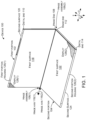
- FIG. 1 shows an example device 100 that has first and second portions 102 and 104 that are rotatably secured together by hinge assemblies 106.
- hinge assemblies 106 In the illustrated implementation, two hinge assemblies 106(1) and 106(2) are employed (e.g., one near each end of the device), but other implementations could employ a single hinge assembly or more than two hinge assemblies.
- the first portion 102 can extend from a hinge end 108 to a distal end 110.
- the second portion 104 also can extend from a hinge end 112 to a distal end 114.
- the hinge assemblies 106 can define two hinge axes 116.
- the first portion 102 can rotate around first hinge axis 116(1) and the second portion 104 can rotate around second hinge axis 116(2).
- the first portion 102 can include opposing first and second major surfaces 118 and 120 (hereinafter, first and second surfaces).
- the second portion 104 can include opposing first and second major surfaces 122 and 124 (hereinafter, first and second surfaces). (Note the second surfaces 120 and 124 are facing away from the viewer and as such are not directly visible in this view, but are shown and designated in subsequent FIGS.).
- the first portion 102 can include a first housing (e.g., first portion housing 126(1)) and the second portion 104 can include a second housing (e.g., second portion housing 126(2)).
- a display 128(1) is positioned on first portion housing 126(1) and display 128(2) is positioned on second portion housing 126(2).
- the displays 128 are positioned on the first surfaces 118 and 122, respectively.
- the displays 128 can be positioned on the first and/or second surfaces 118, 120, 122, and/or 124, respectively.
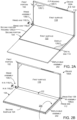
- FIGS. 2A and 2B collectively show another device 100A.
- This device 100A is similar to device 100 of FIG. 1 .
- Device 100A adds a deployable assembly 202.
- the deployable assembly 202 is hingedly attached to the distal end 114 of second portion housing 126(2).
- FIG. 2A shows the deployable assembly 202 deployed.
- FIG. 2B shows the deployable assembly rotated (as indicated by arrow 204) to a storage position against first surface 122 of second portion 104.
- FIGS. 3A-8D collectively show details of example hinge assembly 106(1).
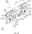
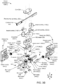
- FIG. 3A is a perspective view of example hinge assembly 106(1) and FIG. 3B is an exploded perspective view of hinge assembly 106(1), both in the 180-degree orientation.
- the hinge assembly 106(1) can include a communication member 302, hinge guides 304, and rotatable links 306.
- the communication member 302 can define hinge shafts 308.
- the hinge shafts 308 can define hinge axes 116.
- the hinge assembly 106(1) can also include a timing element 310 that synchronizes rotation (e.g., extent of rotation) of the first and second portions 102 and 104 around the first and second hinge axes 116.
- the timing element 310 can ensure that 20 degrees of rotation around the first hinge axis 116(1) simultaneously produces 20 degrees of rotation around the second hinge axis 116(2).
- the timing element 310 can be manifest as intermeshing gears.
- the rotatable links 306 can define primary gears 312 (only 312(1) labeled due to space constraints) that can interact with intervening or secondary gears 314 (only 314(2) labeled due to space constraints).
- the secondary gears 314 are rotatably secured relative to primary gears 312 by retainer 316 that can retain the secondary gears 314 relative to the communication member 302.
- the communication member 302 can also receive nested inner and outer barrels 318 and 320 in a rotational relation (e.g., the inner and outer barrels are secured relative to the communication member and can rotate around the hinge axes 116.
- a conductor 322 such as traditional insulated wire(s)s and/or a flexible printed circuit(s) (FPC) can pass from portion 102 through the inner and outer barrels 318 and 320 and to the second portion 104.
- the conductor can be associated with a protective material 323.
- the protective material can provide abrasion resistance to the conductor, maintain crosssectional integrity of the conductor (e.g., keep a rectangular conductor rectangular), and/or influence bending characteristics of the conductor to reduce pinching/binding.
- the protective material 323 is manifest as metal strips on both sides of the conductor 322.
- the conductor 322 can be retained by a cap 324, which secures to retainer 326 over the inner barrels 318, and outer barrels 320.
- the retainer 326 in turn can be secured to the communication member 302.
- the rotatable links 306 can be elongate and extend from a first end 330 to a second end 332.
- the first end 330 can define an aperture 334 and the second end 332 can define an aperture 336. (These elements are only designated relative to link 306(1) in FIG. 3B due to space constraints on the drawing page).
- the hinge shafts 308 can pass through apertures 334.
- the second apertures 336 can receive hinge pins 338.
- the hinge pins can pass through a pair of spaced apart elongate slots 340 in the hinge guides 304 and aperture 336 of the rotatable link 306.
- the hinge pins 338 first pass through one of the spaced apart elongate slots 340, then the aperture 336 on the second end 332 of the rotatable link and then the other of the spaced apart elongate slots 340.
- the hinge pins 338 can retain the rotatable links 306 to the hinge guides 304, while allowing the rotatable link to rotate relative to the hinge guide and to move toward and away from the hinge axis by an amount defined by a length of the elongate slots.
- the rotatable links 306 are secured to an intermediary element (e.g., hinge guides 304).
- the hinge guides are in turn secured to the first and second portion housings.
- the rotatable links can be rotatably secured directly to the first and second portion housings.
- the rotatable links 306, hinge shafts 308, and/or hinge pins 338 can be viewed as an example of a dual rotation assembly 341.
- the dual rotation assembly 341 can allow relative movement between the hinge axes and the first portions while maintaining their relative orientations (e.g., moving from parallel and co-extensive to parallel and not co-extensive).
- the hinge shafts 308 can protrude through the rotatable links 306.
- the protruding portion of the hinge shafts can include cam followers 342 (only 342(2) labeled due to space constraints) and terminal ends 343. The terminal ends can be secured by retainers 344.
- the cams followers 342 can be engaged by cams 348 on biasing arms 346.
- the biasing arms 346 can extend from the cam followers 342 to hinge guides 304.
- the biasing arms 346 can be biased by springs 350 or other biasing elements/mechanisms. In this case, the biasing arms 346 extend through the springs 350 into the hinge guides 304 and thereby retain the springs.
- the springs 350 bias the biasing arms 346 away from the hinge guides 304 and toward the cam followers 342 on the hinge shafts 308.
- the cams followers 342, cams 348, biasing arms 346, and/or springs 350 can be viewed as an example of an orientation biasing assembly 351.
- the orientation biasing assembly 351 can be configured to bias the first and second portions toward, and/or to maintain specific orientations between, the first and second portions (102, 104, FIG. 1 ).
- the hinge guides 304 can be fixedly secured to the respective first and second portion housings ( FIG. 1 , 102 and 104) with fasteners 352 that pass through holes 354 (not all of which are designated with specificity) and connect to the portion housings. Further, the distance between the hinge shafts 308 is also fixed (e.g., the distance between hinge shaft 308(1) and hinge shaft 308(2) does not change during rotation of the first and second portions).
- the rotatable links 306 can also allow relative movement between the hinge assembly 106 and first and second portion housings 126.
- Rotatable link 306(1) is secured to hinge guide 304(1) by hinge pin 338(1).
- the hinge pin itself can move linearly relative to the hinge guide 304(1) as defined by a length of elongate slots 340(1).
- rotatable link 306(2) is secured to hinge guide 304(2) by hinge pin 338(2).
- the hinge pin itself can move linearly relative to the hinge guide 304(2) as defined by a length of elongate slots 340(2)
- rotatable link 306(1) can rotate around hinge shaft 308(1) and rotatable link 306(2) can rotate around hinge shaft 308(2).
- the rotational links can provide rotational and linear movement between the hinge shafts 308 and the hinge guides 304 (and hence the first and second portion housings 126).
- the rotatable links 306 include a tension adjustment mechanism 356 that can control an amount of friction between aperture 334 and hinge shaft 308.
- the rotatable links bend back on themselves at apertures 334.
- the rotatable links can have a hairpin shape.
- Holes 358 can receive a threaded fastener 360 that can be used to adjust a gap G (see FIG. 4D ) to increase or decrease the friction at the aperture 334 (e.g., between the aperture and the hinge shaft 308) to perform the function of the tension adjustment mechanism 356.
- gap G can represent a diameter of aperture 334.
- Hinge shaft 308 passes through aperture 334.
- the hinge shaft 308 can have a diameter D.
- Gap G can be adjusted with fastener 360 to control the amount of interference and hence friction between the hinge shaft and the rotatable link. For example, tightening fastener 360 can decrease gap G and increase interference with the hinge shaft 308.
- This interference can cause the hinge portions to maintain a given orientation, such as 135 degrees between the first and second portions ( FIG. 1 , 102 and 104) set by the user. Then if the user wants to change the orientation, the user can supply enough force to rotate the first and second portions, but they do not rotate on their own without this external force.
- the fasteners 360 can be adjusted during device assembly so that the device rotates within a predefined torque range.
- FIG. 4C shows springs 350 biasing the biasing arms 346 toward hinge shafts 308.
- the biasing arms' cams 348 include an arcuate recess 402 positioned between two extended lobes 404 and 406. At this orientation, the lobes 404 are contacting elongate flattened sides 408 of the cam followers 342 resulting in mild compression of spring 350.
- FIGS. 4C and 4D show the first portion housing 126(1) can define a first hinge end void 403 of a first width W 1 (e.g., open space between first surface 118 and second surface 120).
- the second portion housing 126(2) can define a second hinge end void 403(1) of a second width W 2 (e.g, open space between first surface 122 and second surface 124).
- the hinge assembly 106 as measured at the rotatable link 306(1) around hinge shaft 308(1) can have a third width W 3 that is less than the first width W 1 .
- the hinge assembly 106 as measured at the rotatable link 306(2) around hinge shaft 308(2) can have a fourth width W 4 that is less than the second width W 2 .
- this difference in width can allow relative movement of the first portion housing 126(1) relative to the hinge assembly 106 (e.g., relative to hinge shaft 308(1)).
- the difference in width e.g., W 2 versus W 4
- This relative movement can protect the hinge assembly 106 from damage during rotation as will be explained in more detail below.
- FIGS. 5A-5D show the hinge assembly at a 90-degree orientation (e.g., 45-degrees of rotation around each hinge axis 116 from the zero-degree orientation of FIGS. 4A-4C ).
- FIG. 5C shows cam lobes 404 contacting rounded ends 502 of cam followers 342. This contact forces the biasing arms 346 away from the hinge axes 116 and substantially compresses springs 350 (e.g., springs are more compressed than in zero-degree orientation).
- This highly compressed state of springs 350 can be viewed as a high potential energy state (e.g., a relatively large amount of energy is stored in the springs) when compared to the zero-degree orientation of FIGS. 4A-4D (and the yet to be discussed 180-degree orientation of FIGS. 6A-6D ).
- this potential energy combined with the cam profile leading from lobe 404(1) to recess 402(1) can bias the hinge assembly 106(1) toward the 180-degree orientation.
- the curved ends 502 of cam followers 342 start to transition from cam lobes 404 to cam recesses 402.
- the potential energy in the springs 350 can cause the biasing arm to rotate to the 180-degree orientation (via conversion of potential energy in the spring to kinetic energy moving the biasing arm).
- the hinge arm can rotate automatically from the high potential energy state at 150 degrees to the relatively low potential energy state at 180 degrees.
- a similar process can occur from 210 degrees to 180 degrees.
- the degree ranges listed here are provided only for purposes of explanation. The degree ranges involved in this automatic movement and bias toward the 180-degree orientation can be selected based upon the width and shape of the cam lobes 404 and 406 and/or cam recesses 402.
- FIGS. 6A-6D show the hinge assembly at a 180-degree orientation (e.g., 90-degrees of rotation around each hinge axis 116 from the zero-degree orientation of FIGS. 4A-4C ).
- the hinge assembly is configured to automatically rotate to the 180-degree orientation as the first and second portions (102 and 104, FIG. 1 ) are rotated toward this 'open' orientation.
- This particular implementation can achieve this automatic rotation via the shape of the cams 348 and/or cam followers 342 as well as the spring force biasing them toward one another.
- This implementation can also be biased to maintain this 180-degree orientation based on the cam shape and the corresponding cam follower shape.
- the elongate slots 340 can allow lateral movement (orthogonal toward and away from the hinge axes 116) of the rotatable links 306 relative to the hinge guides 304. This lateral movement can allow full engagement of the cams 348 and cam followers 342. This creates a bias to maintain this 180-degree orientation in that rotation in either direction takes an input of energy to compress the springs 350.
- deployable assembly 202 on second portion housing 126(2) is beginning to contact the first portion housing 126(1).
- Any forces, such as those indicated by arrows 704, to cause further rotation of the first and second portions can stress the hinge assembly 106(1) and/or portion housings 126.
- Such forces where likely to damage the hinge assembly and produce catastrophic failure of one or more hinge assembly elements and/or other device elements.
- the present expandable hinge assembly implementations can reduce or eliminate such damage.
- first ends 330 of rotatable links 306 are proximate to the second surfaces 120 and 124 of portion housings 126.
- the hinge end voids 403 are centrally located (e.g., between the hinge shafts 308).
- the hinge ends of first surfaces 118 and 122 are very close to one another (touching or almost touching in some implementations). This distance or space is represented as S 1 .
- FIGS. 8A-8D show how hinge assembly 106(1) can reduce stress build-up that could otherwise compromise the integrity of the device 100.
- the deployable assembly 202 can function as a fulcrum.
- forces represented by arrows 804 are experienced by the hinge ends 108 and 112 of the first and second portion housings 126 and the hinge assembly 106(1).
- hinge assembly 106(1) can expand when exposed to forces 804 to reduce or eliminate any damage.
- rotation at both ends of rotatable links 306 can allow relative movement between the portion housings 126.
- the rotatable links' first ends 330 can rotate around hinge shafts 308.
- the rotatable links' second ends 332 can rotate around hinge pins 338.
- the hinge pins are fixed relative to the portion housings 126 (via hinge guides (304, FIG. 3B )) and the hinge shafts are fixed relative to one another by the communication member (302, FIG. 3B ).
- the rotatable links 306 allow the hinge ends 108 and 112 of the first and second portion housings 126 to move away from one another (the overall device dimensions expand at the hinge assembly).
- This hinge expansion is evident in FIG. 8D by comparing the distance or space represented as S 2 between the first surfaces 118 and 122 with space S 1 of FIG. 7D .
- the expansion is evident by looking at the hinge end voids 403.
- a majority of the hinge end voids 403 are now outside of the first ends 330 of the rotatable links 306 (e.g., between the first ends 330 and the second surfaces 120 and 124). This can be compared to FIG. 7D where a majority of the hinge end voids 403 are between the first ends 330 and the second surfaces 118 and 122.
- the hinge expansion allows space S 2 to be equivalent to a thickness S 3 of the deployable assembly 202.
- This feature can further decrease the tendency of the deployable assembly to act as a fulcrum and can thereby decrease further force transfer to the hinge assembly 106(1) from forces 804. This aspect can still further reduce the likelihood of device failure from stress forces 804.
- the expandable hinge assembly e.g., expandable device at the hinge end that engages the hinge assembly
- Individual elements of the hinge assemblies can be made from various materials, such as metals, plastics, and/or composites. These materials can be prepared in various ways, such as in the form of sheet metals, die cast metals, machined metals, 3D printed materials, molded or 3D printed plastics, and/or molded or 3D printed composites, among others, and/or any combination of these materials and/or preparations can be employed.
- the present hinge assembly concepts can be utilized with any type of device, such as but not limited to notebook computers, smart phones, wearable smart devices, tablets, and/or other types of existing, developing, and/or yet to be developed devices.
- hinge assemblies and devices are contemplated beyond those shown above relative to FIGS. 1-8D .
- One example includes a device comprising a first portion housing and a second portion housing.
- the first portion housing defining a first hinge end void of a first width and the second portion housing defining a second hinge end void of a second width and a hinge assembly rotatably coupling hinge ends of the first portion housing and the second portion housing.
- the hinge assembly having a third width in the first hinge end void that is less than the first width and having a fourth width in the second hinge end void that is less that the second width.
- the hinge assembly secured to the first housing by a first rotatable link that allows linear movement between the hinge assembly and the first portion housing within the first hinge end void, and the hinge assembly secured to the second housing by a second rotatable link that allows linear movement between the hinge assembly and the second portion housing within the second hinge end void.
- Another example can include any of the above and/or below examples where the hinge assembly comprises a first hinge shaft and the first portion housing comprises a first hinge pin.
- Another example can include any of the above and/or below examples where a first end of the first rotatable link rotates about the first hinge shaft and a second end of the first rotatable link rotates around the first hinge pin to allow the linear movement of the hinge assembly within the first hinge end void.
- Another example can include any of the above and/or below examples where the hinge assembly comprises a second hinge shaft and the second portion housing comprises a second hinge pin.
- Another example can include any of the above and/or below examples where a first end of the second rotatable link rotates about the second hinge shaft and a second end of the second rotatable link rotates around the second hinge pin to allow the linear movement of the hinge assembly within the second hinge end void.
- Another example can include any of the above and/or below examples where the first hinge pin is positioned in an elongate slot in the first portion housing and wherein the first rotatable link and the first hinge pin can move perpendicular to the first portion housing along the elongate slot.
- Another example can include any of the above and/or below examples where the device further comprises an orientation biasing assembly configured to bias the first portion housing to specific orientations relative to the second portion housing.
- Another example can include any of the above and/or below examples where the specific orientations comprise 180 degrees.
- Another example can include any of the above and/or below examples where the orientation biasing assembly operates on a first hinge shaft around which the first portion rotates.
- Another example can include any of the above and/or below examples where the first hinge shaft defines a cam follower.
- orientation biasing assembly comprises a biasing arm that defines a cam that engages the cam follower of the first hinge shaft.
- Another example can include any of the above and/or below examples where the device further comprises a biasing mechanism configured to bias the cam against the cam follower.
- biasing mechanism comprises a spring
- Another example can include any of the above and/or below examples where the spring is positioned between the first portion housing and the biasing arm.
- Another example can include any of the above and/or below examples where linear movement occurs when the hinge end of the first portion housing experiences stress forces at the hinge assembly.
- Another example can include any of the above and/or below examples where an extent of the linear movement is defined as a difference between the first width and the third width.
- Another example includes a device comprising a first portion housing and a second portion housing, a hinge assembly positioned between the first portion housing and the second portion housing and comprising first and second rotatable links.
- the first rotatable link extending along a length from a first end that rotates around a first hinge axis to a second end that rotates relative to the first portion housing.
- the second rotatable link extending along a length from a first end that rotates around a second hinge axis to a second end that rotates relative to the second portion housing.
- Another example can include any of the above and/or below examples where the second end of the first rotatable link rotates around a hinge pin fixed to the first portion housing.
- Another example can include any of the above and/or below examples where the hinge pin is fixed directly to the first portion housing or wherein the hinge pin is fixed to an intermediary element that is fixed to the first portion housing.
- Another example includes a device comprising a first portion housing and a second portion housing, a hinge assembly positioned between the first portion housing and the second portion housing and defining a hinge shaft, and a rotatable link extending along a length from a first end that rotates around the hinge shaft to a second end that rotates relative to the first portion housing to allow linear movement perpendicular to the hinge shaft between the first portion housing and the rotatable link.
Landscapes
- Engineering & Computer Science (AREA)
- Computer Hardware Design (AREA)
- Theoretical Computer Science (AREA)
- Physics & Mathematics (AREA)
- Human Computer Interaction (AREA)
- General Engineering & Computer Science (AREA)
- General Physics & Mathematics (AREA)
- Mechanical Engineering (AREA)
- Mathematical Physics (AREA)
- Pivots And Pivotal Connections (AREA)
- Telephone Set Structure (AREA)
Description
- The
US 2018/066465 A1 relates to devices, such as computing devices, that have hinged portions. One example can include a first portion and a second portion. The first portion can define a first hinge axis and can be resiliently biased toward the first hinge axis. The second portion can define a second hinge axis and can be resiliently biased toward the second hinge axis. A first cam can operate relative to the first hinge axis and is slidably secured to the first portion. A second cam can operate relative to the second hinge axis and can be slidably secured to the first portion. When the first and second portions are oriented at an acute angle the second cam can force the second portion away from the second hinge axis while the first cam can allow the first portion to remain biased toward the first hinge axis. - The accompanying drawings illustrate implementations of the concepts conveyed in the present document. Features of the illustrated implementations can be more readily understood by reference to the following description taken in conjunction with the accompanying drawings. Like reference numbers in the various drawings are used wherever feasible to indicate like elements. Further, the left-most numeral of each reference number conveys the FIG. and associated discussion where the reference number is first introduced. Where space permits, elements and their associated reference numbers are both shown on the drawing page for the reader's convenience. Otherwise, only the reference numbers are shown.
-
FIGS. 1 ,2A ,2B ,3A ,4A ,5A ,6A ,7A , and8A show perspective views of example devices in accordance with some implementations of the present concepts. -
FIG. 3B shows an exploded perspective view of an example device in accordance with some implementations of the present concepts. -
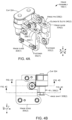
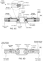
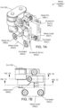
FIGS. 4B ,5B ,6B ,7B , and8B show elevational views of example devices in accordance with some implementations of the present concepts. -
FIGS. 4C-4D ,5C-5D ,6C-6D ,7C-7D , and8C-8D , show sectional views of example devices in accordance with some implementations of the present concepts. - The present concepts relate to devices, such as computing devices employing expandable hinge assemblies that can rotationally secure first and second device portions relative to a hinge axis, such as a first hinge axis that relates to the first portion and a second hinge axis that relates to the second portion. As the device portions are rotated to a closed position (e.g., closed book position), components of the device and/or foreign objects between the two portions can cause forces to be imparted on the hinge assembly that could damage the hinge assembly. The expandable nature of the hinge assembly can allow hinge ends of the first and second portions to move away from one another when exposed to these forces. The expansion can protect the hinge assembly and/or components, such as displays that are proximate to the hinge assembly.
- Introductory
FIG. 1 shows anexample device 100 that has first andsecond portions hinge assemblies 106. In the illustrated implementation, two hinge assemblies 106(1) and 106(2) are employed (e.g., one near each end of the device), but other implementations could employ a single hinge assembly or more than two hinge assemblies. - The
first portion 102 can extend from ahinge end 108 to adistal end 110. Thesecond portion 104 also can extend from ahinge end 112 to adistal end 114. In this example, thehinge assemblies 106 can define twohinge axes 116. Thefirst portion 102 can rotate around first hinge axis 116(1) and thesecond portion 104 can rotate around second hinge axis 116(2). Thefirst portion 102 can include opposing first and secondmajor surfaces 118 and 120 (hereinafter, first and second surfaces). Similarly, thesecond portion 104 can include opposing first and secondmajor surfaces 122 and 124 (hereinafter, first and second surfaces). (Note thesecond surfaces - In some implementations, the
first portion 102 can include a first housing (e.g., first portion housing 126(1)) and thesecond portion 104 can include a second housing (e.g., second portion housing 126(2)). In the illustrated example, a display 128(1) is positioned on first portion housing 126(1) and display 128(2) is positioned on second portion housing 126(2). In this case, thedisplays 128 are positioned on thefirst surfaces displays 128 can be positioned on the first and/orsecond surfaces -
FIGS. 2A and 2B collectively show anotherdevice 100A. Thisdevice 100A is similar todevice 100 ofFIG. 1 .Device 100A adds adeployable assembly 202. In this example, thedeployable assembly 202 is hingedly attached to thedistal end 114 of second portion housing 126(2).FIG. 2A shows thedeployable assembly 202 deployed.FIG. 2B shows the deployable assembly rotated (as indicated by arrow 204) to a storage position againstfirst surface 122 ofsecond portion 104. -
FIGS. 3A-8D collectively show details of example hinge assembly 106(1). -
FIG. 3A is a perspective view of example hinge assembly 106(1) andFIG. 3B is an exploded perspective view of hinge assembly 106(1), both in the 180-degree orientation. The hinge assembly 106(1) can include acommunication member 302,hinge guides 304, androtatable links 306. Thecommunication member 302 can definehinge shafts 308. Thehinge shafts 308 can definehinge axes 116. - The hinge assembly 106(1) can also include a
timing element 310 that synchronizes rotation (e.g., extent of rotation) of the first andsecond portions second hinge axes 116. For instance, thetiming element 310 can ensure that 20 degrees of rotation around the first hinge axis 116(1) simultaneously produces 20 degrees of rotation around the second hinge axis 116(2). - In the illustrated implementation, the
timing element 310 can be manifest as intermeshing gears. For instance, therotatable links 306 can define primary gears 312 (only 312(1) labeled due to space constraints) that can interact with intervening or secondary gears 314 (only 314(2) labeled due to space constraints). Thesecondary gears 314 are rotatably secured relative toprimary gears 312 byretainer 316 that can retain thesecondary gears 314 relative to thecommunication member 302. - The
communication member 302 can also receive nested inner andouter barrels hinge axes 116. Aconductor 322, such as traditional insulated wire(s)s and/or a flexible printed circuit(s) (FPC) can pass fromportion 102 through the inner andouter barrels second portion 104. The conductor can be associated with aprotective material 323. The protective material can provide abrasion resistance to the conductor, maintain crosssectional integrity of the conductor (e.g., keep a rectangular conductor rectangular), and/or influence bending characteristics of the conductor to reduce pinching/binding. In the illustrated configuration, theprotective material 323 is manifest as metal strips on both sides of theconductor 322. Theconductor 322 can be retained by acap 324, which secures toretainer 326 over theinner barrels 318, andouter barrels 320. Theretainer 326 in turn can be secured to thecommunication member 302. - The
rotatable links 306 can be elongate and extend from afirst end 330 to asecond end 332. Thefirst end 330 can define anaperture 334 and thesecond end 332 can define anaperture 336. (These elements are only designated relative to link 306(1) inFIG. 3B due to space constraints on the drawing page). Thehinge shafts 308 can pass throughapertures 334. Thesecond apertures 336 can receive hinge pins 338. The hinge pins can pass through a pair of spaced apartelongate slots 340 in the hinge guides 304 andaperture 336 of therotatable link 306. Stated another way, the hinge pins 338 first pass through one of the spaced apartelongate slots 340, then theaperture 336 on thesecond end 332 of the rotatable link and then the other of the spaced apartelongate slots 340. Thus, the hinge pins 338 can retain therotatable links 306 to the hinge guides 304, while allowing the rotatable link to rotate relative to the hinge guide and to move toward and away from the hinge axis by an amount defined by a length of the elongate slots. In this case, therotatable links 306 are secured to an intermediary element (e.g., hinge guides 304). The hinge guides are in turn secured to the first and second portion housings. In other cases, the rotatable links can be rotatably secured directly to the first and second portion housings. - From one perspective, the
rotatable links 306, hingeshafts 308, and/or hingepins 338 can be viewed as an example of adual rotation assembly 341. Thedual rotation assembly 341 can allow relative movement between the hinge axes and the first portions while maintaining their relative orientations (e.g., moving from parallel and co-extensive to parallel and not co-extensive). - The
hinge shafts 308 can protrude through therotatable links 306. The protruding portion of the hinge shafts can include cam followers 342 (only 342(2) labeled due to space constraints) and terminal ends 343. The terminal ends can be secured byretainers 344. Thecams followers 342 can be engaged bycams 348 on biasingarms 346. The biasingarms 346 can extend from thecam followers 342 to hinge guides 304. The biasingarms 346 can be biased bysprings 350 or other biasing elements/mechanisms. In this case, the biasingarms 346 extend through thesprings 350 into the hinge guides 304 and thereby retain the springs. In turn, thesprings 350 bias the biasingarms 346 away from the hinge guides 304 and toward thecam followers 342 on thehinge shafts 308. From one perspective, thecams followers 342,cams 348, biasingarms 346, and/or springs 350 can be viewed as an example of anorientation biasing assembly 351. Theorientation biasing assembly 351 can be configured to bias the first and second portions toward, and/or to maintain specific orientations between, the first and second portions (102, 104,FIG. 1 ). - The hinge guides 304 can be fixedly secured to the respective first and second portion housings (
FIG. 1 , 102 and 104) withfasteners 352 that pass through holes 354 (not all of which are designated with specificity) and connect to the portion housings. Further, the distance between thehinge shafts 308 is also fixed (e.g., the distance between hinge shaft 308(1) and hinge shaft 308(2) does not change during rotation of the first and second portions). Therotatable links 306 can also allow relative movement between thehinge assembly 106 and first andsecond portion housings 126. Rotatable link 306(1) is secured to hinge guide 304(1) by hinge pin 338(1). The hinge pin itself can move linearly relative to the hinge guide 304(1) as defined by a length of elongate slots 340(1). Similarly, rotatable link 306(2) is secured to hinge guide 304(2) by hinge pin 338(2). The hinge pin itself can move linearly relative to the hinge guide 304(2) as defined by a length of elongate slots 340(2). - At its opposite end, rotatable link 306(1) can rotate around hinge shaft 308(1) and rotatable link 306(2) can rotate around hinge shaft 308(2). Thus, the rotational links can provide rotational and linear movement between the
hinge shafts 308 and the hinge guides 304 (and hence the first and second portion housings 126). - In the illustrated implementation, the
rotatable links 306 include atension adjustment mechanism 356 that can control an amount of friction betweenaperture 334 and hingeshaft 308. In this case, the rotatable links bend back on themselves atapertures 334. Stated another way, the rotatable links can have a hairpin shape.Holes 358 can receive a threadedfastener 360 that can be used to adjust a gap G (seeFIG. 4D ) to increase or decrease the friction at the aperture 334 (e.g., between the aperture and the hinge shaft 308) to perform the function of thetension adjustment mechanism 356. - Stated another way, gap G can represent a diameter of
aperture 334.Hinge shaft 308 passes throughaperture 334. Thehinge shaft 308 can have a diameter D. Gap G can be adjusted withfastener 360 to control the amount of interference and hence friction between the hinge shaft and the rotatable link. For example, tighteningfastener 360 can decrease gap G and increase interference with thehinge shaft 308. - This interference can cause the hinge portions to maintain a given orientation, such as 135 degrees between the first and second portions (
FIG. 1 , 102 and 104) set by the user. Then if the user wants to change the orientation, the user can supply enough force to rotate the first and second portions, but they do not rotate on their own without this external force. Thefasteners 360 can be adjusted during device assembly so that the device rotates within a predefined torque range. -
FIG. 4C showssprings 350 biasing the biasingarms 346 towardhinge shafts 308. In this case, the biasing arms'cams 348 include anarcuate recess 402 positioned between twoextended lobes lobes 404 are contacting elongate flattenedsides 408 of thecam followers 342 resulting in mild compression ofspring 350. -
FIGS. 4C and 4D show the first portion housing 126(1) can define a firsthinge end void 403 of a first width W1 (e.g., open space betweenfirst surface 118 and second surface 120). Similarly, the second portion housing 126(2) can define a second hinge end void 403(1) of a second width W2 (e.g,, open space betweenfirst surface 122 and second surface 124). Thehinge assembly 106 as measured at the rotatable link 306(1) around hinge shaft 308(1) can have a third width W3 that is less than the first width W1. Thehinge assembly 106 as measured at the rotatable link 306(2) around hinge shaft 308(2) can have a fourth width W4 that is less than the second width W2. - As will be described below relative to
FIGS. 5D-8D , this difference in width (e.g., W1 versus W3) can allow relative movement of the first portion housing 126(1) relative to the hinge assembly 106 (e.g., relative to hinge shaft 308(1)). The difference in width (e.g., W2 versus W4) can allow relative movement of the second portion housing 126(2) relative to the hinge assembly 106 (e.g., relative to hinge shaft 308(2)). This relative movement can protect thehinge assembly 106 from damage during rotation as will be explained in more detail below. -
FIGS. 5A-5D show the hinge assembly at a 90-degree orientation (e.g., 45-degrees of rotation around eachhinge axis 116 from the zero-degree orientation ofFIGS. 4A-4C ). -
FIG. 5C showscam lobes 404 contacting rounded ends 502 ofcam followers 342. This contact forces the biasingarms 346 away from the hinge axes 116 and substantially compresses springs 350 (e.g., springs are more compressed than in zero-degree orientation). This highly compressed state ofsprings 350 can be viewed as a high potential energy state (e.g., a relatively large amount of energy is stored in the springs) when compared to the zero-degree orientation ofFIGS. 4A-4D (and the yet to be discussed 180-degree orientation ofFIGS. 6A-6D ). - As rotation continues this potential energy, combined with the cam profile leading from lobe 404(1) to recess 402(1) can bias the hinge assembly 106(1) toward the 180-degree orientation. For instance, at about 150 degrees, the curved ends 502 of
cam followers 342 start to transition fromcam lobes 404 to cam recesses 402. At this point, the potential energy in thesprings 350 can cause the biasing arm to rotate to the 180-degree orientation (via conversion of potential energy in the spring to kinetic energy moving the biasing arm). Thus, the hinge arm can rotate automatically from the high potential energy state at 150 degrees to the relatively low potential energy state at 180 degrees. A similar process can occur from 210 degrees to 180 degrees. The degree ranges listed here are provided only for purposes of explanation. The degree ranges involved in this automatic movement and bias toward the 180-degree orientation can be selected based upon the width and shape of thecam lobes -
FIGS. 6A-6D show the hinge assembly at a 180-degree orientation (e.g., 90-degrees of rotation around eachhinge axis 116 from the zero-degree orientation ofFIGS. 4A-4C ). As mentioned above, the hinge assembly is configured to automatically rotate to the 180-degree orientation as the first and second portions (102 and 104,FIG. 1 ) are rotated toward this 'open' orientation. - This particular implementation can achieve this automatic rotation via the shape of the
cams 348 and/orcam followers 342 as well as the spring force biasing them toward one another. This implementation can also be biased to maintain this 180-degree orientation based on the cam shape and the corresponding cam follower shape. Further, theelongate slots 340 can allow lateral movement (orthogonal toward and away from the hinge axes 116) of therotatable links 306 relative to the hinge guides 304. This lateral movement can allow full engagement of thecams 348 andcam followers 342. This creates a bias to maintain this 180-degree orientation in that rotation in either direction takes an input of energy to compress thesprings 350. -
FIGS. 7A-7D show the hinge assembly at about a 350-degree orientation (e.g., 175-degrees of rotation around eachhinge axis 116 from the zero-degree orientation ofFIGS. 4A-4C ). -
FIG. 7C shows that biasingarms 346 are still in contact with thecam followers 342 of thehinge shafts 308. Specifically,cam lobes 406 ofcams 348 are contacting elongate flattenedsides 702. This is similar toFIG. 4C wherecam lobes 404 contacted elongate flattenedsides 408. This contact forces the biasingarms 346 slightly back from the hinge axes 116 and mildly compresses springs 350. - At this orientation, as seen in
FIGS. 7C and 7D ,deployable assembly 202 on second portion housing 126(2) is beginning to contact the first portion housing 126(1). Any forces, such as those indicated byarrows 704, to cause further rotation of the first and second portions can stress the hinge assembly 106(1) and/orportion housings 126. Traditionally, such forces where likely to damage the hinge assembly and produce catastrophic failure of one or more hinge assembly elements and/or other device elements. However, the present expandable hinge assembly implementations can reduce or eliminate such damage. - Note in
FIG. 7D that the first ends 330 ofrotatable links 306 are proximate to thesecond surfaces portion housings 126. Stated another way, the hinge end voids 403 are centrally located (e.g., between the hinge shafts 308). Further, as indicated at 706, the hinge ends offirst surfaces -
FIGS. 8A-8D show how hinge assembly 106(1) can reduce stress build-up that could otherwise compromise the integrity of thedevice 100. As forces represented byarrows 704 are applied to the first andsecond portion housings 126, thedeployable assembly 202 can function as a fulcrum. With the deployable assembly acting as a fulcrum, forces represented byarrows 804 are experienced by the hinge ends 108 and 112 of the first andsecond portion housings 126 and the hinge assembly 106(1). - In a traditional hinge design,
forces 804 could result in a failure of the device. However, hinge assembly 106(1) can expand when exposed toforces 804 to reduce or eliminate any damage. In this particular implementation, rotation at both ends ofrotatable links 306 can allow relative movement between theportion housings 126. Specifically, the rotatable links' first ends 330 can rotate around hingeshafts 308. The rotatable links' second ends 332 can rotate around hinge pins 338. The hinge pins are fixed relative to the portion housings 126 (via hinge guides (304,FIG. 3B )) and the hinge shafts are fixed relative to one another by the communication member (302,FIG. 3B ). However, by being able to rotate at both ends, therotatable links 306 allow the hinge ends 108 and 112 of the first andsecond portion housings 126 to move away from one another (the overall device dimensions expand at the hinge assembly). - This hinge expansion is evident in
FIG. 8D by comparing the distance or space represented as S2 between thefirst surfaces FIG. 7D . Alternatively or additionally, the expansion is evident by looking at the hinge end voids 403. A majority of the hinge end voids 403 are now outside of the first ends 330 of the rotatable links 306 (e.g., between the first ends 330 and thesecond surfaces 120 and 124). This can be compared toFIG. 7D where a majority of the hinge end voids 403 are between the first ends 330 and thesecond surfaces - In this particular implementation, the hinge expansion allows space S2 to be equivalent to a thickness S3 of the
deployable assembly 202. This feature can further decrease the tendency of the deployable assembly to act as a fulcrum and can thereby decrease further force transfer to the hinge assembly 106(1) fromforces 804. This aspect can still further reduce the likelihood of device failure fromstress forces 804. Thus, the expandable hinge assembly (e.g., expandable device at the hinge end that engages the hinge assembly) can protect the device from damage and thereby enhance reliability and the user experience. - Individual elements of the hinge assemblies can be made from various materials, such as metals, plastics, and/or composites. These materials can be prepared in various ways, such as in the form of sheet metals, die cast metals, machined metals, 3D printed materials, molded or 3D printed plastics, and/or molded or 3D printed composites, among others, and/or any combination of these materials and/or preparations can be employed.
- The present hinge assembly concepts can be utilized with any type of device, such as but not limited to notebook computers, smart phones, wearable smart devices, tablets, and/or other types of existing, developing, and/or yet to be developed devices.
- Various methods of manufacture, assembly, and/or use for hinge assemblies and devices are contemplated beyond those shown above relative to
FIGS. 1-8D . - Although techniques, methods, devices, systems, etc., pertaining to expandable hinge assemblies are described in language specific to structural features and/or methodological acts, it is to be understood that the subject matter defined in the appended claims is not limited to the specific features or acts described. Rather, the specific features and acts are disclosed as example forms of implementing the claimed methods, devices, systems, etc.
- Various examples are described above. Additional examples are described below. One example includes a device comprising a first portion housing and a second portion housing. The first portion housing defining a first hinge end void of a first width and the second portion housing defining a second hinge end void of a second width and a hinge assembly rotatably coupling hinge ends of the first portion housing and the second portion housing. The hinge assembly having a third width in the first hinge end void that is less than the first width and having a fourth width in the second hinge end void that is less that the second width. The hinge assembly secured to the first housing by a first rotatable link that allows linear movement between the hinge assembly and the first portion housing within the first hinge end void, and the hinge assembly secured to the second housing by a second rotatable link that allows linear movement between the hinge assembly and the second portion housing within the second hinge end void.
- Another example can include any of the above and/or below examples where the hinge assembly comprises a first hinge shaft and the first portion housing comprises a first hinge pin.
- Another example can include any of the above and/or below examples where a first end of the first rotatable link rotates about the first hinge shaft and a second end of the first rotatable link rotates around the first hinge pin to allow the linear movement of the hinge assembly within the first hinge end void.
- Another example can include any of the above and/or below examples where the hinge assembly comprises a second hinge shaft and the second portion housing comprises a second hinge pin.
- Another example can include any of the above and/or below examples where a first end of the second rotatable link rotates about the second hinge shaft and a second end of the second rotatable link rotates around the second hinge pin to allow the linear movement of the hinge assembly within the second hinge end void.
- Another example can include any of the above and/or below examples where the first hinge pin is positioned in an elongate slot in the first portion housing and wherein the first rotatable link and the first hinge pin can move perpendicular to the first portion housing along the elongate slot.
- Another example can include any of the above and/or below examples where the device further comprises an orientation biasing assembly configured to bias the first portion housing to specific orientations relative to the second portion housing.
- Another example can include any of the above and/or below examples where the specific orientations comprise 180 degrees.
- Another example can include any of the above and/or below examples where the orientation biasing assembly operates on a first hinge shaft around which the first portion rotates.
- Another example can include any of the above and/or below examples where the first hinge shaft defines a cam follower.
- Another example can include any of the above and/or below examples where the orientation biasing assembly comprises a biasing arm that defines a cam that engages the cam follower of the first hinge shaft.
- Another example can include any of the above and/or below examples where the device further comprises a biasing mechanism configured to bias the cam against the cam follower.
- Another example can include any of the above and/or below examples where the biasing mechanism comprises a spring.
- Another example can include any of the above and/or below examples where the spring is positioned between the first portion housing and the biasing arm.
- Another example can include any of the above and/or below examples where linear movement occurs when the hinge end of the first portion housing experiences stress forces at the hinge assembly.
- Another example can include any of the above and/or below examples where an extent of the linear movement is defined as a difference between the first width and the third width.
- Another example includes a device comprising a first portion housing and a second portion housing, a hinge assembly positioned between the first portion housing and the second portion housing and comprising first and second rotatable links. The first rotatable link extending along a length from a first end that rotates around a first hinge axis to a second end that rotates relative to the first portion housing. The second rotatable link extending along a length from a first end that rotates around a second hinge axis to a second end that rotates relative to the second portion housing.
- Another example can include any of the above and/or below examples where the second end of the first rotatable link rotates around a hinge pin fixed to the first portion housing.
- Another example can include any of the above and/or below examples where the hinge pin is fixed directly to the first portion housing or wherein the hinge pin is fixed to an intermediary element that is fixed to the first portion housing.
- Another example includes a device comprising a first portion housing and a second portion housing, a hinge assembly positioned between the first portion housing and the second portion housing and defining a hinge shaft, and a rotatable link extending along a length from a first end that rotates around the hinge shaft to a second end that rotates relative to the first portion housing to allow linear movement perpendicular to the hinge shaft between the first portion housing and the rotatable link.
Claims (12)
- A device (100), comprising:a first portion housing (126(1)) and a second portion housing (126(2)), wherein the first portion housing (126(1)) defines a first hinge end void (403(1)) of a first width (W1) and the second portion housing (126(2)) defines a second hinge end void (403(2)) of a second width (W2); anda hinge assembly (106(1)) positioned between the first portion housing (126(1)) and the second portion housing (126(2)) and including a communication member (302), a first and second hinge guide (304(1), 304(2)), and a first and second rotatable link (306(1), 306(2)), wherein the communication member (302) defines a first and second hinge shaft (308(1), 308(2)) defining a respective first and second hinge axis (116(1), 116(2)) with a distance between the first hinge shaft (308(1)) and the second hinge shaft (308(2)) being fixed, the first and second rotatable links (306(1), 306(2)) are secured to the respective first and second hinge guides (304(1), 304(2)), and the first and second hinge guides (304(1), 304(2)) are secured to the respective first and second portion housings (126(1), 126(2)),wherein:the hinge assembly (106(1)) rotatably couples a first hinge end (108) of the first portion housing (126(1)) and a second hinge end (112) of the second portion housing (126(2)), the hinge assembly (106(1)) as measured at the first rotatable link (306(1)) around the first hinge shaft (308(1)) having a third width (W3) in the first hinge end void (403(1)) that is less than the first width (W1), and the hinge assembly (106(1)) as measured at the second rotatable link (306(2)) around the second hinge shaft (308(2)) having a fourth width (W4) in the second hinge end void (403(2)) that is less that the second width (W2);the hinge assembly (106(1)) is secured to the first portion housing (126(1)) by the first rotatable link (306(1)) that allows linear movement between the hinge assembly (106(1)) and the first portion housing (126(1)) within the first hinge end void (403(1)) in a direction perpendicular to the first hinge shaft (308(1)),and the hinge assembly (106(1)) is secured to the second portion housing (126(2)) by the second rotatable link (306(2)) that allows linear movement between the hinge assembly (106(1)) and the second portion housing (126(2)) within the second hinge end void (403(2)) in a direction perpendicular to the second hinge shaft (308(2));the first and second rotatable links (306(1), 306(2)) are elongate and extend along a length from a respective first end (330(1), 330(2)) that rotates around the respective first and second hinge shafts (308(1), 308(2)) to a respective second end (332(1), 332(2)) that rotates around a respective first and second hinge pin (338(1), 338(2)), which is fixed relative to the respective first and second portion housings (126(1), 126(2)) via the respective first and second hinge guides (304(1), 304(2)), to allow the respective linear movement between the first portion housing (126(1)) and the first rotatable link (306(1)) in the direction perpendicular to the first hinge shaft (308(1)),and between the second portion housing (126(2)) and the second rotatable link (306(2)) in the direction perpendicular to the second hinge shaft (308(2)), 116(2)) to allow the first and second hinge ends (108, 112) of the respective first and second portion housings (126(1), 126(2)) to move away from one another so that the overall device dimensions expand at the hinge assembly (106(1)).
- The device (100) of claim 1, wherein the first end (330(1)) of the first rotatable link (306(1)) rotates about the first hinge shaft (308(1)) and the second end (332(1)) of the first rotatable link (306(1)) rotates around the first hinge pin (338(1)) to allow the linear movement of the hinge assembly (106(1)) within the first hinge end void (403(1)).
- The device (100) of claim 2, wherein the first end (330(2)) of the second rotatable link (306(2)) rotates about the second hinge shaft (308(2)) and the second end (332(2)) of the second rotatable link (306(2)) rotates around the second hinge pin (338(2)) to allow the linear movement of the hinge assembly (106(1)) within the second hinge end void (403(2)).
- The device (100) of claim 2, wherein the first hinge pin (338(1)) is positioned in an elongate slot (340(1)) in the first portion housing (126(1)) and wherein the first rotatable link (306(1)) and the first hinge pin (338(1)) can move perpendicular to the first portion housing (126(1)) along the elongate slot (340(1)).
- The device (100) of claim 1, further comprising an orientation biasing assembly (351) configured to bias the first portion housing (126(1)) to specific orientations relative to the second portion housing (126(2)).
- The device (100) of claim 5, wherein the specific orientations comprise 180 degrees.
- The device (100) of claim 5, wherein the orientation biasing assembly (351) operates on the first hinge shaft (308(1)) around which the first portion housing (126(1)) rotates.
- The device (100) of claim 7, wherein the first hinge shaft (308(1)) defines a cam follower (342(1)).
- The device (100) of claim 8, wherein the orientation biasing assembly (351) comprises a biasing arm (346(1)) that defines a cam (348(1)) that engages the cam follower (342(1)) of the first hinge shaft (308(1)).
- The device (100) of claim 9, further comprising a biasing mechanism configured to bias the cam (348(1)) against the cam follower (342(1)).
- The device (100) of claim 10, wherein the biasing mechanism comprises a spring (350(1)).
- The device of claim 11, wherein the spring (350(1)) is positioned between the first portion housing (126(1)) and the biasing arm (346(1)).
Applications Claiming Priority (2)
| Application Number | Priority Date | Filing Date | Title |
|---|---|---|---|
| US15/938,757 US11091944B2 (en) | 2018-03-28 | 2018-03-28 | Hinged device |
| PCT/US2019/023492 WO2019190892A1 (en) | 2018-03-28 | 2019-03-22 | Hinged device |
Publications (2)
| Publication Number | Publication Date |
|---|---|
| EP3756064A1 EP3756064A1 (en) | 2020-12-30 |
| EP3756064B1 true EP3756064B1 (en) | 2025-06-25 |
Family
ID=66041736
Family Applications (1)
| Application Number | Title | Priority Date | Filing Date |
|---|---|---|---|
| EP19715712.6A Active EP3756064B1 (en) | 2018-03-28 | 2019-03-22 | Hinged device |
Country Status (3)
| Country | Link |
|---|---|
| US (1) | US11091944B2 (en) |
| EP (1) | EP3756064B1 (en) |
| WO (1) | WO2019190892A1 (en) |
Families Citing this family (16)
| Publication number | Priority date | Publication date | Assignee | Title |
|---|---|---|---|---|
| WO2019035833A1 (en) * | 2017-08-17 | 2019-02-21 | Hewlett-Packard Development Company, L.P. | Dual-axis hinge assembly for electronic devices |
| TWI673545B (en) * | 2018-06-21 | 2019-10-01 | 兆利科技工業股份有限公司 | A Hinge Module For The Foldable Type Device |
| US11181950B2 (en) * | 2018-07-24 | 2021-11-23 | Microsoft Technology Licensing, Llc | Hinged device |
| US11106248B2 (en) | 2019-04-10 | 2021-08-31 | Microsoft Technology Licensing, Llc | Hinged device |
| WO2020214176A1 (en) * | 2019-04-18 | 2020-10-22 | Hewlett-Packard Development Company, L.P. | Electronic devices with hinge assemblies |
| US10831244B1 (en) * | 2019-09-18 | 2020-11-10 | Robert Charles DeMaio | Hinge mechanism for electronic devices |
| CN211820363U (en) * | 2020-01-19 | 2020-10-30 | 杭州安费诺飞凤通信部品有限公司 | Hinge with a hinge body |
| JP7355685B2 (en) * | 2020-03-18 | 2023-10-03 | ニデックプレシジョン株式会社 | Thrust conversion mechanism |
| US11599155B2 (en) * | 2020-04-21 | 2023-03-07 | Microsoft Technology Licensing, Llc | Hinged device |
| US11365573B2 (en) * | 2020-05-14 | 2022-06-21 | Fositek Corporation | Double-screen rotary shaft structure |
| KR102844000B1 (en) * | 2020-07-08 | 2025-08-11 | 삼성전자 주식회사 | Foldable electronic device including display protection structure |
| US11720151B2 (en) * | 2020-08-03 | 2023-08-08 | Microsoft Technology Licensing, Llc | Hinged device |
| US11669132B2 (en) * | 2020-09-29 | 2023-06-06 | Microsoft Technology Licensing, Llc | Hinge assembly for mobile computing device |
| US11567543B2 (en) * | 2020-09-29 | 2023-01-31 | Microsoft Technology Licensing, Llc | Hinge assembly for mobile computing device |
| US11892883B2 (en) | 2021-04-19 | 2024-02-06 | Microsoft Technology Licensing, Llc | Display device with friction hinge |
| JP2025111228A (en) * | 2024-01-17 | 2025-07-30 | レノボ・シンガポール・プライベート・リミテッド | Display assemblies and electronic devices |
Family Cites Families (41)
| Publication number | Priority date | Publication date | Assignee | Title |
|---|---|---|---|---|
| US3229323A (en) | 1963-10-16 | 1966-01-18 | Hensgen Herbert | Hinge adjusting shim |
| JP2770297B2 (en) | 1993-10-18 | 1998-06-25 | 宏一 渡部 | Movable body opening / closing suppression device |
| JPH10294573A (en) | 1997-04-21 | 1998-11-04 | Kato Electrical Mach Co Ltd | Opening/closing device of opening/closing body |
| US6058671A (en) | 1998-03-24 | 2000-05-09 | Canam Manac Group, Inc. | Shim for modular building panels and method for using the same |
| KR100446902B1 (en) | 2001-12-27 | 2004-09-04 | 엘지전자 주식회사 | The hinge structure of plane-type display device |
| US20040134033A1 (en) | 2002-07-29 | 2004-07-15 | Aaron Raines | Friction hinge assembly for a mirror of a display unit |
| US7536747B2 (en) | 2004-12-23 | 2009-05-26 | Christeson Michael E | Hinge shim and sheet thereof |
| TW200833936A (en) | 2007-02-06 | 2008-08-16 | Mitac Technology Corp | Structure of hinge support rack capable of adjusting clamping force arm |
| US20090070961A1 (en) * | 2007-09-17 | 2009-03-19 | Chia-Ko Chung | Simultaneous-rotating hinge |
| CN201351676Y (en) | 2008-12-10 | 2009-11-25 | 康准电子科技(昆山)有限公司 | Pivot device |
| CN201351674Y (en) | 2008-12-10 | 2009-11-25 | 康准电子科技(昆山)有限公司 | hub |
| US20110072620A1 (en) | 2009-09-28 | 2011-03-31 | Cheng Uei Precision Industry Co., Ltd. | Hinge |
| US8196263B2 (en) | 2009-10-30 | 2012-06-12 | Cheng Uei Precision Industry Co. Ltd. | Hinge |
| US8982542B2 (en) * | 2010-11-17 | 2015-03-17 | Microsoft Technology Licensing, Llc | Hinge mechanism for mobile electronic device |
| TWM422001U (en) * | 2011-07-13 | 2012-02-01 | Quanta Comp Inc | Dual-axis hinge structure and electric device having the same |
| TWI539886B (en) | 2013-09-02 | 2016-06-21 | 宏碁股份有限公司 | Electronic device |
| US9347249B2 (en) | 2013-09-19 | 2016-05-24 | Jon Marshall | Armored vehicle door release system |
| TWM478991U (en) * | 2013-12-17 | 2014-05-21 | First Dome Corp | Parallelism fixing device for dual rotary shaft |
| CN105179459B (en) * | 2014-06-12 | 2021-01-22 | 加藤电机(香港)有限公司 | Double-shaft hinge and terminal machine using same |
| US9563236B2 (en) | 2014-07-11 | 2017-02-07 | Intel Corporation | Adjustable tension wrap end hinge |
| US10801239B2 (en) | 2014-09-16 | 2020-10-13 | Shanghai Yanfeng Jinqiao Automotive Trim Systems Co. Ltd. | Vehicle interior component |
| TWI539889B (en) | 2014-12-01 | 2016-06-21 | 宏碁股份有限公司 | Pivot module and electronic device |
| TWI565886B (en) * | 2015-05-07 | 2017-01-11 | 宏碁股份有限公司 | Hinge structure |
| US9791256B1 (en) | 2016-04-28 | 2017-10-17 | William Beer | Step shim |
| US9857849B1 (en) * | 2016-06-10 | 2018-01-02 | Microsoft Technology Licensing, Llc | Hinged device with wrapped displays |
| US10501973B2 (en) * | 2016-06-14 | 2019-12-10 | Microsoft Technology Licensing, Llc | Hinge with free-stop function |
| US10474203B2 (en) | 2016-09-01 | 2019-11-12 | Microsoft Technology Licensing, Llc | Hinged device |
| US10488882B2 (en) * | 2016-09-02 | 2019-11-26 | Microsoft Technology Licensing, Llc | Electronic device hinge assembly |
| US10364598B2 (en) | 2016-09-02 | 2019-07-30 | Microsoft Technology Licensing, Llc | Hinged device |
| US10241548B2 (en) * | 2016-12-09 | 2019-03-26 | Microsoft Technology Licensing, Llc | Computing device employing a self-spacing hinge assembly |
| US10253804B2 (en) * | 2017-01-24 | 2019-04-09 | Microsoft Technology Licensing, Llc | Hinged device |
| US10465427B2 (en) * | 2017-02-08 | 2019-11-05 | Compal Electronics, Inc. | Electronic device and hinge assembly thereof |
| US10344510B2 (en) * | 2017-06-16 | 2019-07-09 | Microsoft Technology Licensing, Llc | Hinged device |
| TWI641941B (en) * | 2017-08-10 | 2018-11-21 | 宏碁股份有限公司 | Electronic device and hinge structure |
| JP6890829B2 (en) * | 2017-08-17 | 2021-06-18 | 株式会社ナチュラレーザ・ワン | Parallel 2-axis hinges and electronic devices |
| US10795416B2 (en) * | 2017-09-22 | 2020-10-06 | Microsoft Technology Licensing, Llc | Hinged device |
| TWI688323B (en) * | 2017-11-22 | 2020-03-11 | 仁寶電腦工業股份有限公司 | Dual axes hinge and electronic device |
| TWI695665B (en) * | 2018-06-21 | 2020-06-01 | 仁寶電腦工業股份有限公司 | Hinge module and electronic device |
| TWI672580B (en) * | 2018-07-06 | 2019-09-21 | 宏碁股份有限公司 | Foldable electronic device and hinge mechanism thereof |
| US10901466B2 (en) | 2018-08-24 | 2021-01-26 | Microsoft Technology Licensing, Llc | Compact hinge for electronic devices |
| US11106248B2 (en) | 2019-04-10 | 2021-08-31 | Microsoft Technology Licensing, Llc | Hinged device |
-
2018
- 2018-03-28 US US15/938,757 patent/US11091944B2/en active Active
-
2019
- 2019-03-22 EP EP19715712.6A patent/EP3756064B1/en active Active
- 2019-03-22 WO PCT/US2019/023492 patent/WO2019190892A1/en not_active Ceased
Also Published As
| Publication number | Publication date |
|---|---|
| EP3756064A1 (en) | 2020-12-30 |
| US11091944B2 (en) | 2021-08-17 |
| US20190301215A1 (en) | 2019-10-03 |
| WO2019190892A1 (en) | 2019-10-03 |
Similar Documents
| Publication | Publication Date | Title |
|---|---|---|
| US11091944B2 (en) | Hinged device | |
| US10296044B2 (en) | Hinged device | |
| US10545541B1 (en) | Hinged device | |
| US10344510B2 (en) | Hinged device | |
| EP3607413B1 (en) | Hinged device | |
| US11720151B2 (en) | Hinged device | |
| CN108930709B (en) | Hinge structure and electronic device | |
| US20190094917A1 (en) | Hinged device | |
| US20200033917A1 (en) | Hinged device | |
| US10641318B2 (en) | Hinged device | |
| CN109313469B (en) | Hinge device | |
| US11106248B2 (en) | Hinged device | |
| JP2019057131A5 (en) | ||
| EP4150431B1 (en) | Variable friction hinged device | |
| EP4441579B1 (en) | Hinged device | |
| WO2012111634A1 (en) | Hinge device | |
| US7334297B2 (en) | Hinge assembly for foldable electronic device | |
| CN104076874B (en) | Flexible Rotating, closing device and notebook computer | |
| WO2024130629A1 (en) | Folding device | |
| CN110558689A (en) | A connection structure and a wearable product | |
| US12553466B2 (en) | Hinged device with a flexible display |
Legal Events
| Date | Code | Title | Description |
|---|---|---|---|
| STAA | Information on the status of an ep patent application or granted ep patent |
Free format text: STATUS: UNKNOWN |
|
| STAA | Information on the status of an ep patent application or granted ep patent |
Free format text: STATUS: THE INTERNATIONAL PUBLICATION HAS BEEN MADE |
|
| PUAI | Public reference made under article 153(3) epc to a published international application that has entered the european phase |
Free format text: ORIGINAL CODE: 0009012 |
|
| STAA | Information on the status of an ep patent application or granted ep patent |
Free format text: STATUS: REQUEST FOR EXAMINATION WAS MADE |
|
| 17P | Request for examination filed |
Effective date: 20200924 |
|
| AK | Designated contracting states |
Kind code of ref document: A1 Designated state(s): AL AT BE BG CH CY CZ DE DK EE ES FI FR GB GR HR HU IE IS IT LI LT LU LV MC MK MT NL NO PL PT RO RS SE SI SK SM TR |
|
| AX | Request for extension of the european patent |
Extension state: BA ME |
|
| DAV | Request for validation of the european patent (deleted) | ||
| DAX | Request for extension of the european patent (deleted) | ||
| RAP3 | Party data changed (applicant data changed or rights of an application transferred) |
Owner name: MICROSOFT TECHNOLOGY LICENSING, LLC |
|
| STAA | Information on the status of an ep patent application or granted ep patent |
Free format text: STATUS: EXAMINATION IS IN PROGRESS |
|
| 17Q | First examination report despatched |
Effective date: 20220321 |
|
| GRAP | Despatch of communication of intention to grant a patent |
Free format text: ORIGINAL CODE: EPIDOSNIGR1 |
|
| STAA | Information on the status of an ep patent application or granted ep patent |
Free format text: STATUS: GRANT OF PATENT IS INTENDED |
|
| INTG | Intention to grant announced |
Effective date: 20250122 |
|
| GRAS | Grant fee paid |
Free format text: ORIGINAL CODE: EPIDOSNIGR3 |
|
| GRAA | (expected) grant |
Free format text: ORIGINAL CODE: 0009210 |
|
| STAA | Information on the status of an ep patent application or granted ep patent |
Free format text: STATUS: THE PATENT HAS BEEN GRANTED |
|
| AK | Designated contracting states |
Kind code of ref document: B1 Designated state(s): AL AT BE BG CH CY CZ DE DK EE ES FI FR GB GR HR HU IE IS IT LI LT LU LV MC MK MT NL NO PL PT RO RS SE SI SK SM TR |
|
| REG | Reference to a national code |
Ref country code: GB Ref legal event code: FG4D |
|
| REG | Reference to a national code |
Ref country code: CH Ref legal event code: EP |
|
| P01 | Opt-out of the competence of the unified patent court (upc) registered |
Free format text: CASE NUMBER: APP_24751/2025 Effective date: 20250523 |
|
| REG | Reference to a national code |
Ref country code: DE Ref legal event code: R096 Ref document number: 602019071513 Country of ref document: DE |
|
| REG | Reference to a national code |
Ref country code: CH Ref legal event code: EP |
|
| REG | Reference to a national code |
Ref country code: IE Ref legal event code: FG4D |
|
| PG25 | Lapsed in a contracting state [announced via postgrant information from national office to epo] |
Ref country code: FI Free format text: LAPSE BECAUSE OF FAILURE TO SUBMIT A TRANSLATION OF THE DESCRIPTION OR TO PAY THE FEE WITHIN THE PRESCRIBED TIME-LIMIT Effective date: 20250625 |
|
| REG | Reference to a national code |
Ref country code: LT Ref legal event code: MG9D |
|
| PG25 | Lapsed in a contracting state [announced via postgrant information from national office to epo] |
Ref country code: GR Free format text: LAPSE BECAUSE OF FAILURE TO SUBMIT A TRANSLATION OF THE DESCRIPTION OR TO PAY THE FEE WITHIN THE PRESCRIBED TIME-LIMIT Effective date: 20250926 Ref country code: NO Free format text: LAPSE BECAUSE OF FAILURE TO SUBMIT A TRANSLATION OF THE DESCRIPTION OR TO PAY THE FEE WITHIN THE PRESCRIBED TIME-LIMIT Effective date: 20250925 |
|
| PG25 | Lapsed in a contracting state [announced via postgrant information from national office to epo] |
Ref country code: BG Free format text: LAPSE BECAUSE OF FAILURE TO SUBMIT A TRANSLATION OF THE DESCRIPTION OR TO PAY THE FEE WITHIN THE PRESCRIBED TIME-LIMIT Effective date: 20250625 |
|
| PG25 | Lapsed in a contracting state [announced via postgrant information from national office to epo] |
Ref country code: HR Free format text: LAPSE BECAUSE OF FAILURE TO SUBMIT A TRANSLATION OF THE DESCRIPTION OR TO PAY THE FEE WITHIN THE PRESCRIBED TIME-LIMIT Effective date: 20250625 |
|
| PG25 | Lapsed in a contracting state [announced via postgrant information from national office to epo] |
Ref country code: RS Free format text: LAPSE BECAUSE OF FAILURE TO SUBMIT A TRANSLATION OF THE DESCRIPTION OR TO PAY THE FEE WITHIN THE PRESCRIBED TIME-LIMIT Effective date: 20250925 |
|
| PG25 | Lapsed in a contracting state [announced via postgrant information from national office to epo] |
Ref country code: LV Free format text: LAPSE BECAUSE OF FAILURE TO SUBMIT A TRANSLATION OF THE DESCRIPTION OR TO PAY THE FEE WITHIN THE PRESCRIBED TIME-LIMIT Effective date: 20250625 |
|
| REG | Reference to a national code |
Ref country code: NL Ref legal event code: MP Effective date: 20250625 |
|
| PG25 | Lapsed in a contracting state [announced via postgrant information from national office to epo] |
Ref country code: NL Free format text: LAPSE BECAUSE OF FAILURE TO SUBMIT A TRANSLATION OF THE DESCRIPTION OR TO PAY THE FEE WITHIN THE PRESCRIBED TIME-LIMIT Effective date: 20250625 |
|
| PG25 | Lapsed in a contracting state [announced via postgrant information from national office to epo] |
Ref country code: PT Free format text: LAPSE BECAUSE OF FAILURE TO SUBMIT A TRANSLATION OF THE DESCRIPTION OR TO PAY THE FEE WITHIN THE PRESCRIBED TIME-LIMIT Effective date: 20251027 |
|
| REG | Reference to a national code |
Ref country code: AT Ref legal event code: MK05 Ref document number: 1807118 Country of ref document: AT Kind code of ref document: T Effective date: 20250625 |
|
| PG25 | Lapsed in a contracting state [announced via postgrant information from national office to epo] |
Ref country code: IS Free format text: LAPSE BECAUSE OF FAILURE TO SUBMIT A TRANSLATION OF THE DESCRIPTION OR TO PAY THE FEE WITHIN THE PRESCRIBED TIME-LIMIT Effective date: 20251025 |
|
| PG25 | Lapsed in a contracting state [announced via postgrant information from national office to epo] |
Ref country code: AT Free format text: LAPSE BECAUSE OF FAILURE TO SUBMIT A TRANSLATION OF THE DESCRIPTION OR TO PAY THE FEE WITHIN THE PRESCRIBED TIME-LIMIT Effective date: 20250625 Ref country code: SM Free format text: LAPSE BECAUSE OF FAILURE TO SUBMIT A TRANSLATION OF THE DESCRIPTION OR TO PAY THE FEE WITHIN THE PRESCRIBED TIME-LIMIT Effective date: 20250625 |
|
| PG25 | Lapsed in a contracting state [announced via postgrant information from national office to epo] |
Ref country code: CZ Free format text: LAPSE BECAUSE OF FAILURE TO SUBMIT A TRANSLATION OF THE DESCRIPTION OR TO PAY THE FEE WITHIN THE PRESCRIBED TIME-LIMIT Effective date: 20250625 |
|
| PG25 | Lapsed in a contracting state [announced via postgrant information from national office to epo] |
Ref country code: PL Free format text: LAPSE BECAUSE OF FAILURE TO SUBMIT A TRANSLATION OF THE DESCRIPTION OR TO PAY THE FEE WITHIN THE PRESCRIBED TIME-LIMIT Effective date: 20250625 |
|
| PG25 | Lapsed in a contracting state [announced via postgrant information from national office to epo] |
Ref country code: EE Free format text: LAPSE BECAUSE OF FAILURE TO SUBMIT A TRANSLATION OF THE DESCRIPTION OR TO PAY THE FEE WITHIN THE PRESCRIBED TIME-LIMIT Effective date: 20250625 |
|
| PG25 | Lapsed in a contracting state [announced via postgrant information from national office to epo] |
Ref country code: SK Free format text: LAPSE BECAUSE OF FAILURE TO SUBMIT A TRANSLATION OF THE DESCRIPTION OR TO PAY THE FEE WITHIN THE PRESCRIBED TIME-LIMIT Effective date: 20250625 |
|
| PG25 | Lapsed in a contracting state [announced via postgrant information from national office to epo] |
Ref country code: ES Free format text: LAPSE BECAUSE OF FAILURE TO SUBMIT A TRANSLATION OF THE DESCRIPTION OR TO PAY THE FEE WITHIN THE PRESCRIBED TIME-LIMIT Effective date: 20250625 |
|
| PGFP | Annual fee paid to national office [announced via postgrant information from national office to epo] |
Ref country code: GB Payment date: 20260219 Year of fee payment: 8 |
|
| PG25 | Lapsed in a contracting state [announced via postgrant information from national office to epo] |
Ref country code: DK Free format text: LAPSE BECAUSE OF FAILURE TO SUBMIT A TRANSLATION OF THE DESCRIPTION OR TO PAY THE FEE WITHIN THE PRESCRIBED TIME-LIMIT Effective date: 20250625 |
|
| PGFP | Annual fee paid to national office [announced via postgrant information from national office to epo] |
Ref country code: DE Payment date: 20260219 Year of fee payment: 8 |
|
| PG25 | Lapsed in a contracting state [announced via postgrant information from national office to epo] |
Ref country code: IT Free format text: LAPSE BECAUSE OF FAILURE TO SUBMIT A TRANSLATION OF THE DESCRIPTION OR TO PAY THE FEE WITHIN THE PRESCRIBED TIME-LIMIT Effective date: 20250625 |
|
| PLBE | No opposition filed within time limit |
Free format text: ORIGINAL CODE: 0009261 |
|
| STAA | Information on the status of an ep patent application or granted ep patent |
Free format text: STATUS: NO OPPOSITION FILED WITHIN TIME LIMIT |
|
| REG | Reference to a national code |
Ref country code: CH Ref legal event code: L10 Free format text: ST27 STATUS EVENT CODE: U-0-0-L10-L00 (AS PROVIDED BY THE NATIONAL OFFICE) Effective date: 20260507 |