EP3755896B1 - Controller and method - Google Patents
Controller and method Download PDFInfo
- Publication number
- EP3755896B1 EP3755896B1 EP19707286.1A EP19707286A EP3755896B1 EP 3755896 B1 EP3755896 B1 EP 3755896B1 EP 19707286 A EP19707286 A EP 19707286A EP 3755896 B1 EP3755896 B1 EP 3755896B1
- Authority
- EP
- European Patent Office
- Prior art keywords
- fuel
- mass flow
- flow rate
- supply means
- combustor
- Prior art date
- Legal status (The legal status is an assumption and is not a legal conclusion. Google has not performed a legal analysis and makes no representation as to the accuracy of the status listed.)
- Active
Links
Images


Classifications
-
- F—MECHANICAL ENGINEERING; LIGHTING; HEATING; WEAPONS; BLASTING
- F02—COMBUSTION ENGINES; HOT-GAS OR COMBUSTION-PRODUCT ENGINE PLANTS
- F02C—GAS-TURBINE PLANTS; AIR INTAKES FOR JET-PROPULSION PLANTS; CONTROLLING FUEL SUPPLY IN AIR-BREATHING JET-PROPULSION PLANTS
- F02C9/00—Controlling gas-turbine plants; Controlling fuel supply in air- breathing jet-propulsion plants
- F02C9/26—Control of fuel supply
- F02C9/28—Regulating systems responsive to plant or ambient parameters, e.g. temperature, pressure, rotor speed
-
- F—MECHANICAL ENGINEERING; LIGHTING; HEATING; WEAPONS; BLASTING
- F02—COMBUSTION ENGINES; HOT-GAS OR COMBUSTION-PRODUCT ENGINE PLANTS
- F02C—GAS-TURBINE PLANTS; AIR INTAKES FOR JET-PROPULSION PLANTS; CONTROLLING FUEL SUPPLY IN AIR-BREATHING JET-PROPULSION PLANTS
- F02C9/00—Controlling gas-turbine plants; Controlling fuel supply in air- breathing jet-propulsion plants
- F02C9/26—Control of fuel supply
- F02C9/32—Control of fuel supply characterised by throttling of fuel
- F02C9/34—Joint control of separate flows to main and auxiliary burners
-
- F—MECHANICAL ENGINEERING; LIGHTING; HEATING; WEAPONS; BLASTING
- F02—COMBUSTION ENGINES; HOT-GAS OR COMBUSTION-PRODUCT ENGINE PLANTS
- F02C—GAS-TURBINE PLANTS; AIR INTAKES FOR JET-PROPULSION PLANTS; CONTROLLING FUEL SUPPLY IN AIR-BREATHING JET-PROPULSION PLANTS
- F02C9/00—Controlling gas-turbine plants; Controlling fuel supply in air- breathing jet-propulsion plants
- F02C9/48—Control of fuel supply conjointly with another control of the plant
- F02C9/50—Control of fuel supply conjointly with another control of the plant with control of working fluid flow
-
- F—MECHANICAL ENGINEERING; LIGHTING; HEATING; WEAPONS; BLASTING
- F05—INDEXING SCHEMES RELATING TO ENGINES OR PUMPS IN VARIOUS SUBCLASSES OF CLASSES F01-F04
- F05D—INDEXING SCHEME FOR ASPECTS RELATING TO NON-POSITIVE-DISPLACEMENT MACHINES OR ENGINES, GAS-TURBINES OR JET-PROPULSION PLANTS
- F05D2270/00—Control
- F05D2270/01—Purpose of the control system
- F05D2270/09—Purpose of the control system to cope with emergencies
- F05D2270/091—Purpose of the control system to cope with emergencies in particular sudden load loss
-
- F—MECHANICAL ENGINEERING; LIGHTING; HEATING; WEAPONS; BLASTING
- F05—INDEXING SCHEMES RELATING TO ENGINES OR PUMPS IN VARIOUS SUBCLASSES OF CLASSES F01-F04
- F05D—INDEXING SCHEME FOR ASPECTS RELATING TO NON-POSITIVE-DISPLACEMENT MACHINES OR ENGINES, GAS-TURBINES OR JET-PROPULSION PLANTS
- F05D2270/00—Control
- F05D2270/01—Purpose of the control system
- F05D2270/10—Purpose of the control system to cope with, or avoid, compressor flow instabilities
- F05D2270/101—Compressor surge or stall
Definitions
- the present invention relates generally to controllers for gas turbines, to gas turbines comprising such controllers and to methods of controlling such gas turbines.
- WO 2015185413 A1 describes a method for determining a fuel split setting value utilisable for adjusting a fuel split setting for a combustion device, the fuel split setting defining a relation between main fuel and pilot fuel.
- EP2104802 B1 describes a method of controlling a fuel split of a pilot fuel flow and a main fuel flow in a gas turbine combustor in case of load reductions characterised in that the rate of change of fuel demand is monitored and an additional pilot fuel flow is added the amount of which depends on the rate of the change in fuel flow demand.
- US 9,822,710 B2 describes a combustion device control unit and a combustion device, e.g. a gas turbine, which determine on the basis of at least one operating parameter whether the combustion device is in a predefined operating stage.
- a control signal configured for setting a ratio of at least two different input fuel flows to a predetermined value for a predetermined time in case the combustion device is in the predefined operating stage.
- US6,095,793A discloses a unique and useful dynamic control system for the control of a catalytic combustion system for use on a dynamic plant, preferably, a gas turbine engine.
- the dynamic control system facilitates the replacement of conventional flame combustion systems with catalytic combustion systems, which produce far less pollutants, by producing acceptable transient performance of the combustion system.
- a method of controlling the catalytic combustion process comprises the steps of calculating a mass flow of air introduced into the combustor, monitoring a flow of fuel to be combusted within the combustor, monitoring a temperature of the air introduced into the combustor, calculating an inlet temperature set point based on the mass flow and fuel flow, and controlling a pre-burner to heat the air based on the inlet temperature set point, the mass flow, and the temperature of the air. Further, the mass flow may be estimated based on ambient air temperature and pressure, and compressor speed.
- a catalytic combustion gas turbine system is also presented, the operation of which is controlled by a dynamic plant controller which generates a fuel flow rate demand signal to control the flow of fuel to be combusted in response to dynamic plant demands.
- US5,896,736A discloses a rapid acting control system for a gas turbine in an electrical system that is adapted to control fuel and air supply to the turbine to prevent flameout condition in the turbine and includes: a turbine control unit having an air supply controller that controls the position of a plurality of turbine inlet guide vanes (IGVs) in correspondence with at least one turbine condition signal; a load rejection module coupled to the air supplier controller and to a turbine electrical load sensor so as to generate a transient IGV correction signal in correspondence with a sensed turbine electrical load drop condition.
- IGVs turbine inlet guide vanes
- a method of operating a gas turbine to maintain the turbine on-line during a loss of load condition includes the steps of sensing a loss of load condition for the turbine; supplying an inlet guide vane correction signal into an air supply controller coupled to control the position of a plurality of turbine IGVs, the IGV correction signal being independent of other turbine operating condition signals applied to the air supply controller; and adjusting the position of the plurality of IGVs in response to the IGV correction signal to adjust the turbine fuel air mixture in the gas turbine to prevent flameout during a loss of electrical load condition.
- the method typically further includes the step of removing the IGV correction signal after a correction time delay.
- US 2004/216,462 A1 discloses a gas turbo group having a combustion chamber comprising a catalytic burner stage, a pre-burner stage located upstream from the catalytic burner stage, as well as a non-catalytic burner stage located downstream from the catalytic burner stage.
- the pre-burner stage serves to always maintain a temperature at the inlet into the catalytic stage that corresponds at least to a minimum temperature necessary for operating the catalytic burner stage.
- the gas turbo group is operated so that the burner stage located downstream from the catalytic combustion chamber is taken into operation only when the temperature at the outlet from the catalytic stage has reached an upper limit in the presence of a maximum combustion air mass flow.
- US 2014/026,587 A1 discloses a method and system for transient operating of a gas turbine. Operation of the gas turbine the controller determines command values for an inlet air mass flow, fuel mass flow, and for a water or steam mass flow. In order to allow fast transient operation with a stable premix flame at least one command value is dynamically compensated to compensate for the different system dynamics of the supply systems to synchronize the resulting changes in fuel, water, steam, and/or combustion air mass flows, which reach the combustor, so that the fuel to air ratio stays within the combustible limit.
- a method of controlling a gas turbine arranged to supply a load L comprising a compressor arranged to operate at a rotational speed n , a combustor and a fuel supply means comprising a first fuel supply means and a second fuel supply means, wherein the compressor is arranged to provide air to the combustor at a steady state air mass flow rate m ⁇ ⁇ SS and wherein the fuel supply means is arranged to supply fuel at a fuel mass flow rate m tot ⁇ l to the combustor, the method comprising:
- the combustor mass flow rate ⁇ t is a sum of the air mass flow rate and the fuel mass flow rate m total .
- the control of the gas turbine is better adapted for transient events, such as load acceptance and/or load rejection.
- the gas turbine may be better controlled to increase power output, for example more quickly and/or more accurately, during load acceptance, thereby enabling increased loads to be accepted without loss of a pilot flame of the combustor, for example.
- the gas turbine may be better controlled to decrease power output, for example more quickly and/or more accurately, during load rejection, thereby enabling increased loads to be rejected without overheating of a burner of the combustor.
- control of the gas turbine is better adapted for transient events, reducing likelihood of trips, faults, damage and/or deterioration.
- the method is a closed control loop method.
- controlling the proportion Z of the fuel mass flow rate m total as the fuel mass flow rate ⁇ fuel_pilot supplied via the first fuel supply means is based, at least in part, on a previous combustor mass flow rate ⁇ t -1 supplied via the first fuel supply means and/or the compressor in a previous time step t - 1.
- the gas turbine may be controlled based, at least in part, on previous operating conditions.
- controlling the proportion Z of the fuel mass flow rate m total as the fuel mass flow rate ⁇ fuel_pilot supplied via the first fuel supply means is based, at least in part, on the previous combustor mass flow rate ⁇ T -1 supplied via the first fuel supply means and/or the compressor in the previous time step t - 1, wherein the previous combustor mass flow rate ⁇ t -1 is provided from a set thereof.
- the first pilot threshold ⁇ LBO corresponds with loss of a pilot flame of the combustor.
- the second pilot threshold ⁇ TT corresponds with overheating of a burner of the combustor.
- the proportion Z of the fuel mass flow rate m total as the fuel mass flow rate ⁇ fuel_pilot supplied via the first fuel supply means is below the first pilot threshold ⁇ LBO for at most a predetermined first duration.
- the proportion Z of the fuel mass flow rate m total as the fuel mass flow rate ⁇ fuel_pilot supplied via the first fuel supply means is above the second pilot threshold ⁇ TT for at most a predetermined second duration.
- controlling the proportion Z of the fuel mass flow rate m total as the fuel mass flow rate ⁇ fuel_pilot supplied via the first fuel supply means comprises decreasing the proportion Z if the load change ⁇ L to the load L is positive.
- controlling the proportion Z of the fuel mass flow rate m total as the fuel mass flow rate ⁇ fuel_pilot supplied via the first fuel supply means comprises increasing the proportion Z if the load change ⁇ L to the load L is negative.
- controller for a gas turbine comprising a compressor arranged to operate at a rotational speed n , a combustor and a fuel supply means comprising a first fuel supply means and a second fuel supply means, wherein the compressor is arranged to provide air to the combustor at a steady state air mass flow rate m ⁇ ⁇ SS and wherein the fuel supply means is arranged to supply fuel at a fuel mass flow rate m total to the combustor, wherein the controller is arranged to:
- a gas turbine comprising a compressor arranged to operate at a rotational speed n , a combustor and a fuel supply means comprising a first fuel supply means and a second fuel supply means, wherein the compressor is arranged to provide air to the combustor at a steady state air mass flow rate m ⁇ ⁇ SS and wherein the fuel supply means is arranged to supply fuel at a fuel mass flow rate m tot ⁇ l to the combustor, wherein the gas turbine comprises a controller according to the second aspect.
- a tangible non-transient computer-readable storage medium having recorded thereon instructions which when implemented by a controller for a gas turbine, the gas turbine comprising a compressor arranged to operate at a rotational speed n , a combustor and a fuel supply means comprising a first fuel supply means and a second fuel supply means, wherein the compressor is arranged to provide air to the combustor at a steady state air mass flow rate m ⁇ ⁇ SS and wherein the fuel supply means is arranged to supply fuel at a fuel mass flow rate m tot ⁇ l to the combustor, cause the controller to perform a method of controlling the gas turbine, the method according to the first aspect.
- Figure 1 shows a schematic view of a gas turbine 100 of a type that may be used according to an exemplary embodiment.
- the gas turbine 100 comprises a compressor 101, a combustor 102, a compressor turbine 103, a power turbine 104, and an interduct 105.
- the gas turbine 100 comprises a gas generator device which is adapted for generating pressurized working fluid.
- the gas generator device comprises the compressor 101, the combustor 102 and the compressor turbine 103.
- a working fluid, such as air, is injected into the compressor 101.
- the compressor 101 pressurizes the working fluid.
- the arrows in Figure 1 show the flow direction of the working fluid. Downstream of the compressor 101, fuel is injected into the combustor 102. The working fluid, i.e. a part of the working fluid, is mixed with the fuel and is burned. The combustor 102 generates pressurized, high energized working fluid which drives the compressor turbine 103 such that mechanical energy is generated for driving the compressor 101, respectively.
- the hot pressurized, high energized working fluid is guided through an interduct 105 to the power turbine 104.
- the pressurized hot working fluid drives the power turbine 104 for generating torque.
- Figure 2 shows a schematic view of the gas turbine 100 of Figure 1 , in more detail. Particularly, Figure 2 shows schematically the compressor 101, the combustor 102 and the compressor turbine 103 of the gas turbine 100 as shown in Figure 1 in more detail.
- upstream and downstream refer to the flow direction of the airflow and/or working gas flow through the engine unless otherwise stated.
- forward and rearward refer to the general flow of gas through the engine.
- axial, radial and circumferential are made with reference to a rotational axis 20 of the engine.
- the gas turbine 100 comprises, in flow series, an inlet 12, the compressor 101, the combustor 102 and the compressor turbine 103 which are generally arranged in flow series and generally in the direction of a longitudinal or rotational axis 20.
- the gas turbine 100 further comprises a shaft 22 which is rotatable about the rotational axis 20 and which extends longitudinally through the gas turbine 100.
- the shaft 22 drivingly connects the compressor turbine 103 to the compressor 101.
- air 24 which is taken in through the air inlet 12 is compressed by the compressor 101 and delivered to the combustor 102 comprising a burner section 16.
- the burner section 16 comprises a burner plenum 26, one or more combustion chambers 28 defined by a double wall can 27 and at least one burner 30 fixed to each combustion chamber 28.
- the combustion chambers 28 and the burners 30 are located inside the burner plenum 26.
- the compressed air passing through the compressor 12 enters a diffuser 32 and is discharged from the diffuser 32 into the burner plenum 26 from where a portion of the air enters the burner 30 and is mixed with a gaseous or liquid fuel.
- the air/fuel mixture is then burned and the combustion gas 34 or working gas from the combustion is channelled via a transition duct 35 to the compressor turbine 103.
- the compressor turbine 103 comprises a number of blade carrying discs 36 attached to the shaft 22.
- two discs 36 each carry an annular array of turbine blades 38.
- the number of blade carrying discs could be different, i.e. only one disc or more than two discs.
- guiding vanes 40 which are fixed to a stator 42 of the gas turbine 100, are disposed between the turbine blades 38. Between the exit of the combustion chamber 28 and the leading turbine blades 38 inlet guiding vanes 44 are provided.
- the combustion gas from the combustion chamber 28 enters the compressor turbine 103 and drives the turbine blades 38 which in turn rotates the shaft 22.
- the guiding vanes 40, 44 serve to optimise the angle of the combustion or working gas on to the turbine blades 38.
- the compressor 101 comprises an axial series of guide vane stages 46 and rotor blade stages 48.
- Figure 3 shows a schematic view of the gas turbine of Figure 1 , in more detail. Particularly, Figure 3 shows a part of the combustion chamber 28, in more detail.
- Figure 4 shows a schematic view of the gas turbine of Figure 1 , in more detail. Particularly, Figure 4 shows a section of the combustion chamber 28 along a line III-III shown in Figure 3 .
- the combustion chamber 28 is in four parts: a front-end part 120, a swirler part 121, a burner pre-chamber part 122 and a combustion volume 123.
- Main fuel is introduced into the swirler 121 by way of the front-end part 120 through a conduit 124, while pilot fuel enters the burner space through a conduit 125 having at its end a pilot-fuel nozzle 129.
- the main and pilot fuel-flows are derived from a fuel-split valve 126, which is fed with a fuel supply means 127 representing the total fuel supply to the combustion chamber 123.
- the fuel supply means 127 comprises thus a main or first fuel supply means and a pilot or second fuel supply means.
- the main fuel flow enters the swirler 121 through a set of main-fuel nozzles (or injector) 128, from where it is guided along swirler vanes 130, being mixed with incoming compressed air in the process.
- the fuel may be gaseous fuel or liquid fuel.
- the resulting air/fuel mixture maintains a burner flame 30.
- the hot air from this burner flame 30 enters the combustion volume 123.
- a gas turbine will often comprise a number of such combustion chambers 28, in which case the main and pilot fuel-flow distribution will usually be as shown in Figure 5 .
- Figure 5 shows a schematic view of the gas turbine of Figure 1 , in more detail. Particularly, Figure 5 shows the main and pilot fuel-flow distribution for 1, 2, ... N combustion chambers 28.
- the main and pilot fuel-flows are derived from the fuel-split valve 126, which is fed with the fuel supply means 127 representing the total fuel supply to the 1, 2, ... N combustion chambers 28.
- the fuel supply means 127 comprises thus the main or first fuel supply means and the pilot or second fuel supply means.
- Figure 6 shows a schematic view of a controller 600 according to an example not forming part of the claimed invention. Particularly, Figure 6 shows a schematic view of the controller 600 communicatively coupled to the gas turbine 100.
- the controller 600 is for the gas turbine 100.
- the gas turbine 100 comprises the compressor 101 arranged to operate at a rotational speed n , the combustor 102 and the fuel supply means 127 comprising the first fuel supply means and the second fuel supply means, wherein the compressor 101 is arranged to provide air to the combustor 102 at a steady state air mass flow rate m ⁇ ⁇ SS and wherein the fuel supply means 127 is arranged to supply fuel at a fuel mass flow rate m total to the combustor 102.
- the controller 600 is arranged to, responsive to a load change ⁇ L to the load L , control the compressor 101 to provide air to the combustor 102 at a new air mass flow rate m ⁇ ⁇ TR , wherein the new air mass flow rate m ⁇ ⁇ TR is within a range between a first threshold m ⁇ ⁇ LBO and a second threshold m ⁇ ⁇ SUR .
- the controller 600 comprises a real-time model unit 610, a correction factor determination unit 620, an acceleration/deceleration schedule unit 630, a multiplication unit 640, an acceleration/deceleration determination unit 650, a summation unit 660, a Proportional Integral (PI) controller unit 670 and a selector unit 680.
- PI Proportional Integral
- the real-time model unit 610 is arranged to determine an estimate of the new air mass flow rate m ⁇ ⁇ TR . In one example, the real-time model unit 610 is arranged to determine the estimate of the new air mass flow rate m ⁇ ⁇ TR based, at least in part, on a real-time model of the gas turbine 100. In one example, the real-time model unit 610 is arranged to determine the estimate of the new air mass flow rate m ⁇ ⁇ TR based, at least in part, on the rotational speed n . In one example, the real-time model unit 610 is arranged to receive the rotational speed n from the gas turbine 100. In one example, the real-time model unit 610 is arranged to provide the determined estimate of the new air mass flow rate m ⁇ ⁇ TR to the correction factor determination unit 620.
- x ⁇ f x x , h , u , v
- Controls, u , operating conditions, v , and health parameters, h are quantities which may be distinguished by measurement and/or manipulation.
- this gas turbine model may be expanded to include data representing the deteriorated gas turbine 100 (i.e. following use of the gas turbine 100, for example following commissioning and/or extended use thereof).
- Deterioration effects may include efficiency changes, area changes, pressure drops, as well as flow changes and disturbances due to bleed effects, for example.
- the two quantities of capacity and efficiency may be used to model changes in operation of the gas turbine 100 resulting in decreased energy conversion efficiency or component flow characteristics.
- the real-time model is as described in WO 2015/117791 and/or WO 2017/198528 .
- the controller 600 is arranged to, responsive to the load change ⁇ L to the load L, control the compressor 101 to provide air to the combustor 102 at the new air mass flow rate m ⁇ ⁇ TR by determining a correction factor CF for the load change ⁇ L to the load L and adjusting the air mass flow rate m to the new air mass flow rate m ⁇ ⁇ TR based, at least in part, on the determined correction factor CF .
- the correction factor CF comprises and/or is an acceleration correction factor ACF.
- the correction factor CF comprises and/or is a deceleration correction factor DCF.
- the correction factor determination unit 620 is arranged to determine the correction factor CF for the load change ⁇ L to the load L. In one example, the correction factor determination unit 620 is arranged to determine the correction factor CF for the load change ⁇ L to the load L based, at least in part, on the determined estimate of the new air mass flow rate m ⁇ ⁇ TR provided by the real-time model unit 610. In one example, the correction factor determination unit 620 is arranged to determine the correction factor CF based, at least in part, on the rotational speed n . In one example, the correction factor determination unit 620 is arranged to determine the correction factor CF as described with reference to Figures 8 , 9 and 11 .
- the correction factor determination unit 620 is arranged to receive the rotational speed n from the gas turbine 100. In one example, the correction factor determination unit 620 is arranged to provide the determined correction factor CF for the load change ⁇ L to the load L to the multiplication unit 640.
- the correction factor CF is an acceleration correction factor ACF.
- the controller 600 is arranged to, responsive to the load change ⁇ L to the load L , control the compressor 101 to provide air to the combustor 102 at the new air mass flow rate m ⁇ ⁇ TR by determining a rate of change of the rotational speed dn dt corresponding to the load change ⁇ L to the load L and adjusting the air mass flow rate m ⁇ ⁇ SS to the new air mass flow rate m ⁇ ⁇ TR based, at least in part, on the determined correction factor CF and the determined rate of change of the rotational speed dn dt .
- the acceleration/deceleration schedule unit 630 is arranged to determine the rate of change of the rotational speed dn dt corresponding to the load change ⁇ L to the load L . In one example, the acceleration/deceleration schedule unit 630 is arranged to determine the rate of change of the rotational speed dn dt corresponding to the load change ⁇ L to the load L as a function of the rotational speed n , for example, as described below with reference to Figures 10 and/or 12. In one example, this rate of change comprises and/or is an estimated acceleration/deceleration demand of the compressor 101. In one example, the acceleration/deceleration schedule unit 630 is arranged to receive the rotational speed n from the gas turbine 100. In one example, the acceleration/deceleration schedule unit 630 is arranged provide the determined rate of change of the rotational speed dn dt , for example as the estimated acceleration/deceleration demand of the compressor 101, to the multiplication unit 640.
- the controller 600 is arranged to control the compressor 101 to provide air to the combustor 102 at the new air mass flow rate m ⁇ ⁇ TR by adjusting, for example limiting, the air mass flow rate to the new air mass flow rate m ⁇ ⁇ TR based, at least in part, on a product of the determined correction factor CF and the determined rate of change of the rotational speed dn dt .
- the multiplication unit 640 is arranged to multiply (i.e. calculate the product of) the determined correction factor CF provided by the correction factor determination unit 620 and the estimated acceleration/deceleration demand of the compressor 101 provided by the acceleration/deceleration schedule unit 630, thereby providing a corrected acceleration/deceleration demand of the compressor 101.
- the multiplication unit 640 is arranged to provide the product of the determined correction factor CF and the determined rate of change of the rotational speed dn dt to the summation unit 660.
- the controller 600 is arranged to control the compressor 101 to provide air to the combustor 102 at the new fuel mass flow rate m ⁇ ⁇ TR by adjusting, for example limiting, the air mass flow rate to the new air mass flow rate m ⁇ ⁇ TR based on a sum of the determined rate of change of the rotational speed dn dt and the product of the determined correction factor CF and the determined rate of change of the rotational speed dn dt .
- the acceleration/deceleration determination unit 650 is arranged to determine the rate of change of the rotational speed dn dt corresponding to the load change ⁇ L to the load L based on the received rotational speed n (i.e. an actual value rather than an estimate, for example). In one example, the acceleration/deceleration determination unit 650 is arranged to receive the rotational speed n from the gas turbine 100. In one example, the acceleration/deceleration determination unit 650 is arranged to provide the determined rate of change of the rotational speed dn dt to the summation unit 660.
- the summation unit 660 is arranged to sum the determined rate of change of the rotational speed dn dt provided by the acceleration/deceleration determination unit 650 and the product of the determined correction factor CF and the determined rate of change of the rotational speed dn dt (i.e. the corrected acceleration/deceleration demand of the compressor 101) provided by the multiplication unit 640, thereby providing an acceleration/deceleration error of the compressor 101 as a difference between the corrected acceleration/deceleration demand and the actual value provided by the acceleration/deceleration determination unit 650.
- the summation unit 660 is arranged to provide this sum (i.e. the acceleration/deceleration error of the compressor 101) to the PI controller 670.
- the controller 600 is arranged to, responsive to the load change ⁇ L to the load L , control the compressor 101 to provide air to the combustor 102 at the new air mass flow rate m ⁇ ⁇ TR determined from the sum of the determined rate of change of the rotational speed dn dt and the product of the determined correction factor CF and the determined rate of change of the rotational speed dn dt .
- the controller 600 is arranged to, responsive to the load change ⁇ L to the load L, control the fuel supply means 127 to supply fuel at the fuel mass flow rate m tot ⁇ l to the combustor 102. In one example, the controller 600 is arranged to determine the fuel mass flow rate m total corresponding with the new air mass flow rate m ⁇ ⁇ TR .
- the PI controller 670 is arranged to determine the new air mass flow rate m ⁇ ⁇ TR based, at least in part, on the sum, provided by the summation unit 660, of the determined rate of change of the rotational speed dn dt and the product of the determined correction factor CF and the determined rate of change of the rotational speed dn dt (i.e. on the acceleration/deceleration error of the compressor 101). In one example, the PI controller 670 is arranged to provide the determined new total fuel mass flow rate m total to the selector 680.
- the PI controller 670 is arranged to determine the fuel mass flow rate m tot ⁇ l to be supplied by the fuel supply means 127 to the combustor 102 based, at least in part, on the sum, provided by the summation unit 660, of the determined rate of change of the rotational speed dn dt and the product of the determined correction factor CF and the determined rate of change of the rotational speed dn dt (i.e. on the acceleration/deceleration error of the compressor 101). In one example, the PI controller 670 is arranged to provide the determined fuel mass flow rate m total to the selector 680.
- the selector 680 is arranged to provide the determined new total fuel mass flow rate m total to the gas turbine 100, for example to the compressor 101, thereby controlling the gas turbine 100 according to the determined new air mass flow rate m ⁇ ⁇ TR . In one example, the selector 680 is arranged to provide the determined new total fuel mass flow rate m total to the real-time model unit 610, thereby feeding this value back into the real-time model.
- the selector 680 is arranged to provide the determined fuel mass flow rate m total to the gas turbine 100, for example to the fuel supply means 127, thereby controlling the gas turbine 100 according to the determined fuel mass flow rate m total . In one example, the selector 680 is arranged to provide the determined fuel mass flow rate m total to the real-time model unit 610, thereby feeding this value back into the real-time model.
- the real-time model unit 610 receives the rotational speed n from the gas turbine 100. More generally, at S601, the real-time model unit 610 receives all available measurements from the gas turbine 100, for example speeds, pressures and/or temperatures at different engine stations.
- the real-time model unit 610 determines the estimate of the new air mass flow rate m ⁇ ⁇ TR based, at least in part, on the received rotational speed n , as described above, and provides the estimate of the new air mass flow rate m ⁇ ⁇ TR to the correction factor determination unit 620.
- the correction factor determination unit 620 receives the rotational speed n from the gas turbine 100.
- the correction factor determination unit 620 determines the correction factor CF based, at least in part, on the received rotational speed n and the estimate of the new air mass flow rate m ⁇ ⁇ TR provided by the real-time model unit 610, as described above, and provides the determined correction factor CF to the multiplication unit 640.
- the acceleration/deceleration schedule unit 630 receives the rotational speed n from the gas turbine 100.
- the acceleration/deceleration schedule unit 630 determines the rate of change of the rotational speed dn dt corresponding to the load change ⁇ L to the load L as a function of the received rotational speed n as an estimated acceleration/deceleration demand of the compressor 101 and provides an allowable, for example acceptable, permissible, permitted, tolerable or sustainable, acceleration/deceleration demand to the multiplication unit 640.
- the multiplication unit 640 multiplies (i.e. calculates the product of) the determined correction factor CF provided by the correction factor determination unit 620 and the allowable acceleration/deceleration demand of the compressor 101 provided by the acceleration/deceleration schedule unit 630, thereby providing the corrected allowable acceleration/deceleration demand of the compressor 101.
- the multiplication unit 640 provides the corrected allowable acceleration/deceleration demand of the compressor 101 to the summation unit 660.
- the acceleration/deceleration determination unit 650 receives the rotational speed n from the gas turbine 100.
- the acceleration/deceleration determination unit 650 determines the rate of change of the rotational speed dn dt corresponding to the load change ⁇ L to the load L based on the received rotational speed n (i.e. an actual value rather than an estimate, for example) and provides the determined rate of change of the rotational speed dn dt to the summation unit 660.
- the summation unit 660 sums the determined rate of change of the rotational speed dn dt provided by the acceleration/deceleration determination unit 650 and the corrected acceleration/deceleration demand of the compressor 101, thereby providing an acceleration/deceleration error of the compressor 101 as a difference between the corrected acceleration/deceleration demand and the actual value provided by the acceleration/deceleration determination unit 650.
- the summation unit 660 provides this acceleration/deceleration error of the compressor 101 to the PI controller 670.
- the PI controller 670 determines the new fuel mass flow rate m total based, at least in part, on the acceleration/deceleration error of the compressor 101, as described above. In this example, the PI controller 670 determines the fuel mass flow rate m total to be supplied by the fuel supply means 127 to the combustor 102. The PI controller 670 provides the fuel mass flow rate m total to the selector 680.
- the selector 680 provides the determined new fuel mass flow rate to the gas turbine 100, thereby controlling the gas turbine 100 according to the determined new air mass flow rate m ⁇ ⁇ TR .
- the selector 680 provides the determined fuel mass flow rate m tot ⁇ l to the gas turbine 100, for example to the fuel supply means 127, thereby controlling the gas turbine 100 according to the determined fuel mass flow rate m total .
- the selector 680 may provide the total, the pilot and/or the main fuel demands to the gas turbine 100.
- the selector 680 may additionally provide other and/or all demands, for example variable guide vane (VGV) demand and/or blow off valve (BOV) demand, to the gas turbine 100.
- VV variable guide vane
- BOV blow off valve
- the selector 680 provides the determined fuel mass flow rate m tot ⁇ l to the real-time model unit 610, thereby feeding this value back into the real-time model. More generally, at S613, the selector 680 may provide the total, the pilot and/or the main fuel demands to the real-time model unit 610. The selector 680 may additionally provide other and/or all demands, for example variable guide vane (VGV) demand and/or blow off valve (BOV) demand, to the real-time model unit 610.
- VUV variable guide vane
- BOV blow off valve
- Figure 7 shows a schematic view of a method of controlling the gas turbine 100 according to an example not forming part of the claimed invention.
- the method is of controlling the gas turbine 100 arranged to supply the load L, the gas turbine 100 comprising the compressor 101 arranged to operate at a rotational speed n , a combustor 102 and a fuel supply means 127 comprising a first fuel supply means and a second fuel supply means, wherein the compressor 101 is arranged to provide air to the combustor 102 at a steady state air mass flow rate m ⁇ ⁇ SS and wherein the fuel supply means 127 is arranged to supply fuel at a fuel mass flow rate m tot ⁇ l to the combustor 102.
- the compressor 101 is controlled to provide air to the combustor 102 at the new air mass flow rate m ⁇ ⁇ TR , wherein the new air mass flow rate m ⁇ ⁇ TR is within the range between the first threshold m ⁇ ⁇ LBO and the second threshold m ⁇ ⁇ SUR .
- the method comprises repeating S701, for example successively, periodically, regularly and/or irregularly, responsive to subsequent load changes ⁇ L .
- the method may include any of the steps described herein.
- Figure 8 shows a schematic view of a method of controlling the gas turbine 100 according to an example not forming part of the claimed invention. Particularly, Figure 8 shows a pressure map for the gas turbine 100 in which a compressor pressure ratio PR is plotted as a function of compressor air mass flow rate .
- the compressor pressure ratio PR is the ratio of the compressor outlet pressure to the compressor inlet pressure.
- the pressure map includes a running line for a steady state air mass flow rate m ⁇ ⁇ SS , for which the compressor pressure ratio PR is approximately proportional to the compressor air mass flow rate .
- the pressure map includes the first, lower threshold m ⁇ ⁇ LBO , which is the lean blow out (LBO) limit, corresponding with loss of the burner flame 30, at lower compressor pressure ratios PR than the running line for the same compressor air mass flow rate and which diverges away from the running line at higher compressor air mass flow rates .
- the pressure map includes the second, upper threshold m ⁇ ⁇ SUR , which is the surge limit, corresponding with surge instability of the compressor 101, at higher compressor pressure ratios PR than the running line for the same compressor air mass flow rate and which diverges away from the running line at higher compressor air mass flow rates before converging theretowards.
- the pressure map includes a third threshold A ⁇ m ⁇ ⁇ LOW , proximal and parallel to the running line, which is within a range between the steady state air mass flow rate m ⁇ ⁇ SS (i.e. the running line and the first threshold m ⁇ ⁇ LBO .
- the pressure map includes a fourth threshold A ⁇ m ⁇ ⁇ HIGH , proximal and parallel to the running line, which is within a range between the steady state air mass flow rate m ⁇ ⁇ SS and the second threshold m ⁇ ⁇ SUR .
- the third threshold A ⁇ m ⁇ ⁇ LOW and the fourth threshold A ⁇ m ⁇ ⁇ HIGH correspond with moderate transient events.
- the pressure map includes also a plurality, specifically seven in this example, of approximately mutually equispaced rotational speed lines, transverse to the running line, the first threshold m ⁇ ⁇ LBO , the second threshold m ⁇ ⁇ SUR , the third threshold ⁇ m ⁇ ⁇ LOW and the fourth threshold ⁇ m ⁇ ⁇ HIGH .
- Three rotational speed lines n K -1 , n K and n K +1 , corresponding to three adjacent rotational speeds n are labelled.
- Figure 9 shows a schematic view of a method of controlling the gas turbine 100 according to an example not forming part of the claimed invention. Particularly, Figure 9 shows an example of the pressure map, as described with reference to Figure 8 , for acceleration scheduling during load acceptance due to a positive transient load change ⁇ L .
- the gas turbine 100 is controlled to move from the initial steady state air mass flow rate m ⁇ ⁇ SS running line to operate at the new air mass flow rate m ⁇ ⁇ TR , between the steady state air mass flow rate m ⁇ ⁇ SS and the second threshold m ⁇ ⁇ SUR , before returning to operate on the steady state air mass flow rate m ⁇ ⁇ SS running line, following load acceptance.
- the gas turbine 100 may be controlled to operate closer to the second threshold m ⁇ ⁇ SUR , allowing the gas turbine 100 to accept larger positive load changes ⁇ L without surging.
- Figure 10 shows a schematic view of a method of controlling a gas turbine according to an example not forming part of the claimed invention.
- Figure 10 shows a graph of a nominal acceleration schedule in which rate of change of the rotational speed dn dt (i.e. acceleration) is plotted as a function of rotational speed n .
- the acceleration slowly increases as a function of rotational speed n and spikes to a maximum of approximately 3,200 at a rotational speed n of approximately 13,000 before decreasing at higher speeds.
- a normal operating range of the rotational speed n is from approximately 11,000 to 13,000, in this example.
- Figure 11 shows a schematic view of a method of controlling the gas turbine 100 according to an example not forming part of the claimed invention. Particularly, Figure 11 shows an example of the compressor pressure ratio map, as described with reference to Figure 8 , for deceleration scheduling during load rejection due to a negative transient load change ⁇ L .
- the gas turbine 100 is controlled to move from the initial steady state air mass flow rate m ⁇ ⁇ SS running line to operate at the new air mass flow rate m ⁇ ⁇ TR , between the steady state air mass flow rate m ⁇ ⁇ SS and the first threshold m ⁇ ⁇ LBO , before returning to operate on the steady state air mass flow rate m ⁇ ⁇ SS running line, following load rejection.
- the gas turbine 100 may be controlled to operate closer to the first threshold m ⁇ ⁇ LBO , allowing the gas turbine 100 to accept larger negative load changes ⁇ L without loss of flame.
- Figure 12 shows a schematic view of a method of controlling a gas turbine according to an example not forming part of the claimed invention. Particularly, Figure 12 shows a graph of a nominal deceleration schedule in which rate of change of the rotational speed dn dt (i.e. deceleration) is plotted as a function of rotational speed n .
- the acceleration is constant as a function of rotational speed n to approximately 9,000 before decreasing at higher speeds, in this example.
- Figure 13 shows a schematic view of a controller 700 according to an exemplary embodiment. Particularly, Figure 13 shows a schematic view of the controller 700 communicatively coupled to the gas turbine 100.
- the controller 700 comprises the controller 600 or vice versa.
- the controller 700 is for the gas turbine 100.
- the gas turbine 100 comprises the compressor 101 arranged to operate at a rotational speed n , the combustor 102 and the fuel supply means 127 comprising the first fuel supply means and the second fuel supply means, wherein the compressor 101 is arranged to provide air to the combustor 102 at a steady state air mass flow rate m ⁇ ⁇ SS and wherein the fuel supply means 127 is arranged to supply fuel at a fuel mass flow rate m total to the combustor 102.
- the controller 700 is arranged to, responsive to a load change ⁇ L to the load L, control the fuel supply means 127 to supply a proportion Z of the fuel mass flow rate m total as a fuel mass flow rate ⁇ fuel_pilot via the first fuel supply means based, at least in part, on a combustor mass flow rate ⁇ t .
- the combustor mass flow rate ⁇ t is a sum of an air mass flow rate (for example, the steady state air mass flow rate m ⁇ ⁇ SS or the new air mass flow rate m ⁇ ⁇ TR ) and the fuel mass flow rate m total of the air and of the fuel, respectively, provided to the combustor 102 by the compressor 101 and supplied by the fuel supply means 127, respectively, for a current time step t .
- the current time step t may be in a range from 1 ms to 100 ms, preferably from 10 to 50 ms.
- the controller 700 comprises a real-time model unit 710, a one time step delay unit 790, an acceleration/deceleration schedule unit 730, a multiplication unit 740 and a selector unit 780.
- a real-time model unit 710 a one time step delay unit 790, an acceleration/deceleration schedule unit 730, a multiplication unit 740 and a selector unit 780.
- Other arrangements are possible.
- the real-time model unit 710, the acceleration/deceleration schedule unit 730, the multiplication unit 740 and/or the selector unit 780 may comprise and/or be as described above with respect to the real-time model unit 610, the acceleration/deceleration schedule unit 630, the multiplication unit 640 and/or the selector unit 680, respectively.
- the real-time model unit 710 is arranged to determine the combustor mass flow rate m t . In one example, the real-time model unit 710 is arranged to determine the combustor mass flow rate m t based, at least in part, on a real-time model of the gas turbine 100. In one example, the real-time model unit 710 is arranged to determine the combustor mass flow rate m t based, at least in part, on the rotational speed n . In one example, the real-time model unit 710 is arranged to receive the rotational speed n from the gas turbine 100. In one example, the real-time model unit 710 is arranged to provide the determined combustor mass flow rate m t to the time step delay unit 790 and/or to the multiplication unit 740.
- x ⁇ f x x h u v
- Controls, u, operating conditions, v , and health parameters, h are quantities which may be distinguished by measurement and/or manipulation.
- vector y comprises measurable and non-measurable parameters.
- this gas turbine model may be expanded to include data representing the deteriorated gas turbine 100 (i.e. following use of the gas turbine 100, for example following commissioning and/or extended use thereof).
- Deterioration effects may include efficiency changes, area changes, pressure drops, as well as flow changes and disturbances due to bleed effects, for example.
- the two quantities of capacity and efficiency may be used to model changes in operation of the gas turbine 100 resulting in decreased energy conversion efficiency or component flow characteristics.
- the real-time model is as described in WO 2015/117791 and/or WO 2017/198528 .
- the controller 700 is arranged to control the proportion Z of the fuel mass flow rate m total as the fuel mass flow rate ⁇ fuel_pilot supplied via the first fuel supply means is based, at least in part, on a previous combustor mass flow rate ⁇ t -1 supplied in a previous time step t - 1.
- the previous time step t - 1 is one (i.e. only, a single or exactly one) time step preceding the current time step t .
- the time step delay unit 790 is arranged to determine the previous combustor mass flow rate ⁇ t -1 supplied in a previous time step t - 1, for example corresponding to the determined combustor mass flow rate m t for the current time step t received from the real-time model unit 710. In one example, the time step delay unit 790 is arranged to obtain the previous combustor mass flow rate ⁇ t -1 , for example from a memory block, for example a look-up table or a map.
- the controller 700 is arranged to control the proportion Z of the fuel mass flow rate m total as the fuel mass flow rate ⁇ fuel_pilot supplied via the first fuel supply means based, at least in part, on the previous combustor mass flow rate ⁇ T -1 supplied in the previous time step t - 1, wherein the previous combustor mass flow rate ⁇ t -1 is provided from a set thereof.
- the time step delay unit 790 is arranged to obtain the previous combustor mass flow rate ⁇ t -1 for the previous time step t - 1, for example from a memory block, for example a look-up table or a map. In one example, the time step delay unit 790 is arranged to provide the combustor mass flow rate ⁇ t to the acceleration/deceleration schedule unit 730 which contains the memory block, for example a look-up table or a map.
- the controller 700 is arranged to, responsive to the load change ⁇ L to the load L, control the fuel supply means 127 to supply the proportion Z of the fuel mass flow rate m total as the fuel mass flow rate ⁇ fuel_pilot via the first fuel supply means based, at least in part, on an estimated acceleration/deceleration first fuel (also known as pilot) demand obtained from a acceleration/deceleration schedule as a function of the combustor mass flow rate ⁇ t -1 for the previous time step t - 1, for example from an acceleration/deceleration schedule thereof.
- the estimated acceleration/deceleration first fuel demand may be determined generally from a ratio of the fuel mass flow rate ⁇ fuel_pilot to the combustor mass flow rate m: m ⁇ fuel _ pilot m ⁇
- the acceleration/deceleration schedule unit 730 is arranged to determine the estimated acceleration/deceleration first fuel demand based, at least in part, on the combustor mass flow rate ⁇ t -1 for the previous time step t - 1 provided by the time step unit 790. In one example, the acceleration/deceleration schedule unit 730 is arranged to determine the estimated acceleration/deceleration first fuel demand as a ratio of the fuel mass flow rate ⁇ fuel_pilot to the combustor mass flow rate ⁇ t -1 for the previous time step t - 1, for example from an acceleration/deceleration schedule thereof. In one example, the acceleration/deceleration schedule unit 730 is arranged to provide the estimated acceleration/deceleration first fuel demand to the multiplication unit 740.
- the multiplication unit 740 is arranged to multiply (i.e. calculate the product of) the combustor mass flow rate ⁇ t for the current time step t provided by the real-time model unit 710 and the estimated acceleration/deceleration first fuel demand provided (i.e. determined from the combustor mass flow rate ⁇ t -1 for the previous time step t - 1) by the acceleration/deceleration schedule unit 730, thereby providing a corrected acceleration/deceleration first fuel demand.
- the corrected acceleration/deceleration first fuel demand may be thus expressed as: m ⁇ fuel _ pilot ⁇ m ⁇ t m ⁇ t ⁇ 1
- the multiplication unit 740 is arranged to provide the corrected acceleration/deceleration first fuel demand to the selector 780.
- the selector 780 is arranged to provide the corrected acceleration/deceleration first fuel demand to the gas turbine 100, for example to the fuel supply means 127, thereby controlling the gas turbine 100 according to the corrected acceleration/deceleration first fuel demand schedule. In one example, the selector 780 is arranged to provide the corrected acceleration/deceleration first fuel demand to the real-time model unit 710 (thereby feeding this value back into the real-time model) and to the gas turbine 100.
- the proportion Z of the fuel mass flow rate m total as the fuel mass flow rate ⁇ fuel_pilot supplied via the first fuel supply means is within a range between a first pilot threshold ⁇ LBO and a second pilot threshold ⁇ TT .
- the first pilot threshold ⁇ LBO corresponds with loss of a pilot flame of the combustor 102.
- the second pilot threshold ⁇ TT corresponds with overheating of a burner of the combustor 102.
- the first pilot threshold ⁇ LBO is pre-determined for the gas turbine 100, for example according to data obtained therefrom, included in the real-time model and/or in the acceleration/deceleration schedule, as described above.
- the second pilot threshold ⁇ TT is pre-determined for the gas turbine 100, for example according to data obtained therefrom, included in the real-time model and/or in the acceleration/deceleration schedule, as described above.
- the proportion Z of the fuel mass flow rate m total as the fuel mass flow rate ⁇ fuel_pilot supplied via the first fuel supply means is below the first pilot threshold ⁇ LBO for at most a predetermined first duration, for example in a range of 1 to 100 time steps, preferably in a range from 1 to 10 time steps, more preferably in a range from 1 to 5 time steps, for example 3 time steps.
- Temporary deviations below the first pilot threshold ⁇ LBO may be acceptable.
- the time step may be in a range from 1 ms to 100 ms, preferably from 10 to 50 ms.
- the proportion Z of the fuel mass flow rate m total as the fuel mass flow rate ⁇ fuel_pilot supplied via the first fuel supply means is above the second pilot threshold ⁇ TT for at most a predetermined second duration, for example in a range of 1 to 100 time steps, preferably in a range from 1 to 10 time steps, more preferably in a range from 1 to 5 time steps, for example 3 time steps.
- Temporary deviations above the second pilot threshold ⁇ TT may be acceptable.
- the time step may be in a range from 1 ms to 100 ms, preferably from 10 to 50 ms.
- controlling the proportion Z of the fuel mass flow rate m total as the fuel mass flow rate ⁇ fuel_pilot supplied via the first fuel supply means comprises decreasing the proportion Z if the load change ⁇ L to the load L is positive.
- controlling the proportion Z of the fuel mass flow rate m total as the fuel mass flow rate ⁇ fuel_pilot supplied via the first fuel supply means comprises increasing the proportion Z if the load change ⁇ L to the load L is negative.
- the real-time model unit 710 receives all available measurements from the gas turbine 100, for example speeds, pressures and/or temperatures at different engine stations.
- the real-time model unit 710 determines the combustor mass flow rate ⁇ t based, at least in part, the fuel mass flow rate ⁇ total for the current time step t, as described above, and provides the combustor mass flow rate m t to the to the time step unit 790.
- the time step unit 790 obtains the previous combustor mass flow rate ⁇ t -1 for the previous time step t - 1, for example from a memory block for example a look-up table or a map, and provides the previous combustor mass flow rate ⁇ t -1 for the previous time step t - 1 to the acceleration/deceleration schedule unit 730.
- the acceleration/deceleration schedule unit 730 determines the estimated acceleration/deceleration first fuel demand based, at least in part, on the combustor mass flow rate ⁇ t -1 for the previous time step t - 1 provided by the time step unit 790, from an acceleration/deceleration schedule thereof, and provides the estimated acceleration/deceleration first fuel demand to the multiplication unit 740.
- the real-time model unit 710 provides the combustor mass flow rate m t to the multiplication unit 740.
- the multiplication unit 740 multiplies (i.e. calculates the product of) the combustor mass flow rate ⁇ t for the current time step t provided by the real-time model unit 710 and the estimated acceleration/deceleration first fuel demand provided (i.e. determined from the combustor mass flow rate ⁇ t -1 for the previous time step t - 1) by the acceleration/deceleration schedule unit 730, thereby providing the corrected acceleration/deceleration first fuel demand expressed as: m ⁇ fuel _ pilot ⁇ m ⁇ t m ⁇ t ⁇ 1
- the multiplication unit 740 provides the corrected acceleration/deceleration first fuel demand to the selector 780.
- the selector 780 provides the corrected acceleration/deceleration first fuel demand to the gas turbine 100, for example to the fuel supply means 127, thereby controlling the gas turbine 100 according to the corrected acceleration/deceleration first fuel demand. More generally, at S1307, the selector 780 may provide the total, the pilot and/or the main fuel demands to the gas turbine 100. The selector 780 may additionally provide other and/or all demands, for example variable guide vane (VGV) demand and/or blow off valve (BOV) demand, to the gas turbine 100.
- VV variable guide vane
- BOV blow off valve
- the selector 780 provides the corrected acceleration/deceleration first fuel demand to the real-time model unit 710, thereby feeding this value back into the real-time model. More generally, at S1308, the selector 780 may provide the total, the pilot and/or the main fuel demands to the real-time model unit 710. The selector 780 may additionally provide other and/or all demands, for example variable guide vane (VGV) demand and/or blow off valve (BOV) demand, to the real-time model unit 710.
- VV variable guide vane
- BOV blow off valve
- Figure 14 shows a schematic view of a method of controlling the gas turbine 100 according to an exemplary embodiment.
- the method is of controlling the gas turbine 100 arranged to supply the load L, the gas turbine 100 comprising the compressor 101 arranged to operate at a rotational speed n , a combustor 102 and a fuel supply means 127 comprising a first fuel supply means and a second fuel supply means, wherein the compressor 101 is arranged to provide air to the combustor 102 at a steady state air mass flow rate m ⁇ ⁇ SS and wherein the fuel supply means 127 is arranged to supply fuel at a fuel mass flow rate m tot ⁇ l to the combustor 102.
- the fuel supply means 127 is controlled to supply the proportion Z of the fuel mass flow rate m total as the fuel mass flow rate ⁇ fuel_pilot via the first fuel supply means based, at least in part, on the combustor mass flow rate ⁇ t .
- the method comprises repeating S1401, for example successively, periodically, regularly and/or irregularly, responsive to subsequent load changes ⁇ L .
- the method may comprise any of the method steps described herein, for example including as described with respect to Figure 7 .
- Figure 15 shows a schematic view of a method of controlling the gas turbine 100 according to an exemplary embodiment.
- Figure 15 shows a pilot split map (also known as an acceleration/deceleration pilot demand schedule) for the gas turbine 100 in which a pilot fuel demand split is plotted as a function of combustor mass flow rate ⁇ t .
- the pilot split map includes a running line for a steady state combustor mass flow rate ⁇ t , for which the pilot fuel demand split is approximately inversely proportional to the combustor mass flow rate m.
- the fuel map includes the first, lower pilot threshold ⁇ LBO , which is the lean blow out (LBO) limit, corresponding with loss of the pilot flame, at lower pilot fuel demand splits than the running line for the same combustor mass flow rate ⁇ and which converges towards the running line at higher combustor mass flow rate m.
- the pressure map includes the second, upper pilot threshold ⁇ TT , which is the tip temperature limit, corresponding with overheating of the burner, at higher pilot fuel demand splits than the running line for the same combustor mass flow rate ⁇ and which converges towards the running line at higher combustor mass flow rate m.
- Figure 16 shows a schematic view of a method of controlling the gas turbine 100 according to an exemplary embodiment.
- Figure 16 shows an example of the pilot split map, as described with reference to Figure 15 , for acceleration scheduling during load acceptance due to a positive transient load change ⁇ L .
- the gas turbine 100 is controlled to move from the initial pilot fuel demand split on the running line, corresponding with the previous combustor mass flow rate ⁇ t -1 supplied in a previous time step t - 1, to operate at the new pilot fuel demand split between the steady state combustor mass flow rate ⁇ and the first pilot threshold ⁇ LBO (i.e.
- the gas turbine 100 may be controlled to operate closer to the first pilot threshold ⁇ LBO , allowing the gas turbine 100 to accept larger positive load changes ⁇ L without loss of pilot flame.
- Figure 17 shows a schematic view of a method of controlling the gas turbine 100 according to an exemplary embodiment.
- Figure 17 shows an example of the pilot split map, as described with reference to Figure 15 , for deceleration scheduling during load rejection due to a negative transient load change ⁇ L .
- the gas turbine 100 is controlled to move from the initial pilot fuel demand split on the running line, corresponding with the previous combustor mass flow rate ⁇ t -1 supplied in a previous time step t - 1, to operate at the new pilot fuel demand split between the steady state combustor mass flow rate ⁇ and the second pilot threshold ⁇ TT (i.e.
- the gas turbine 100 may be controlled to operate closer to the second pilot threshold ⁇ TT , allowing the gas turbine 100 to accept larger negative load changes ⁇ L without overheating of the pilot nozzle.
Landscapes
- Engineering & Computer Science (AREA)
- Chemical & Material Sciences (AREA)
- Combustion & Propulsion (AREA)
- Mechanical Engineering (AREA)
- General Engineering & Computer Science (AREA)
- Physics & Mathematics (AREA)
- Fluid Mechanics (AREA)
- Control Of Positive-Displacement Air Blowers (AREA)
- Control Of Turbines (AREA)
- Regulation And Control Of Combustion (AREA)
Description
- The present invention relates generally to controllers for gas turbines, to gas turbines comprising such controllers and to methods of controlling such gas turbines.
- Conventional controllers for gas turbines implement relatively conservative control methods such that the gas turbines are operated at relatively higher safety margins. These conservative control methods impose restrictions on transient events, such as load acceptance and load rejection, such that only relatively small loads may be accepted or rejected.
-
WO 2015185413 A1 describes a method for determining a fuel split setting value utilisable for adjusting a fuel split setting for a combustion device, the fuel split setting defining a relation between main fuel and pilot fuel. -
EP2104802 B1 describes a method of controlling a fuel split of a pilot fuel flow and a main fuel flow in a gas turbine combustor in case of load reductions characterised in that the rate of change of fuel demand is monitored and an additional pilot fuel flow is added the amount of which depends on the rate of the change in fuel flow demand. -
US 9,822,710 B2 -
US6,095,793A discloses a unique and useful dynamic control system for the control of a catalytic combustion system for use on a dynamic plant, preferably, a gas turbine engine. The dynamic control system facilitates the replacement of conventional flame combustion systems with catalytic combustion systems, which produce far less pollutants, by producing acceptable transient performance of the combustion system. - A method of controlling the catalytic combustion process comprises the steps of calculating a mass flow of air introduced into the combustor, monitoring a flow of fuel to be combusted within the combustor, monitoring a temperature of the air introduced into the combustor, calculating an inlet temperature set point based on the mass flow and fuel flow, and controlling a pre-burner to heat the air based on the inlet temperature set point, the mass flow, and the temperature of the air. Further, the mass flow may be estimated based on ambient air temperature and pressure, and compressor speed. A catalytic combustion gas turbine system is also presented, the operation of which is controlled by a dynamic plant controller which generates a fuel flow rate demand signal to control the flow of fuel to be combusted in response to dynamic plant demands.
-
US5,896,736A discloses a rapid acting control system for a gas turbine in an electrical system that is adapted to control fuel and air supply to the turbine to prevent flameout condition in the turbine and includes: a turbine control unit having an air supply controller that controls the position of a plurality of turbine inlet guide vanes (IGVs) in correspondence with at least one turbine condition signal; a load rejection module coupled to the air supplier controller and to a turbine electrical load sensor so as to generate a transient IGV correction signal in correspondence with a sensed turbine electrical load drop condition. A method of operating a gas turbine to maintain the turbine on-line during a loss of load condition includes the steps of sensing a loss of load condition for the turbine; supplying an inlet guide vane correction signal into an air supply controller coupled to control the position of a plurality of turbine IGVs, the IGV correction signal being independent of other turbine operating condition signals applied to the air supply controller; and adjusting the position of the plurality of IGVs in response to the IGV correction signal to adjust the turbine fuel air mixture in the gas turbine to prevent flameout during a loss of electrical load condition. The method typically further includes the step of removing the IGV correction signal after a correction time delay. -
US 2004/216,462 A1 discloses a gas turbo group having a combustion chamber comprising a catalytic burner stage, a pre-burner stage located upstream from the catalytic burner stage, as well as a non-catalytic burner stage located downstream from the catalytic burner stage. The pre-burner stage serves to always maintain a temperature at the inlet into the catalytic stage that corresponds at least to a minimum temperature necessary for operating the catalytic burner stage. According to the invention, the gas turbo group is operated so that the burner stage located downstream from the catalytic combustion chamber is taken into operation only when the temperature at the outlet from the catalytic stage has reached an upper limit in the presence of a maximum combustion air mass flow. -
US 2014/026,587 A1 discloses a method and system for transient operating of a gas turbine. Operation of the gas turbine the controller determines command values for an inlet air mass flow, fuel mass flow, and for a water or steam mass flow. In order to allow fast transient operation with a stable premix flame at least one command value is dynamically compensated to compensate for the different system dynamics of the supply systems to synchronize the resulting changes in fuel, water, steam, and/or combustion air mass flows, which reach the combustor, so that the fuel to air ratio stays within the combustible limit. - Hence, there is a need to improve control of gas turbines, for example control related to transient events, such as load acceptance and load rejection.
- According to the present disclosure there is provided a method of controlling a gas turbine, a controller for a gas turbine, a gas turbine comprising such a controller and a tangible non-transient computer-readable storage medium as set forth in the appended claims. Other features of the invention will be apparent from the dependent claims, and the description which follows.
- According to a first aspect, there is provided a method of controlling a gas turbine arranged to supply a load L, the gas turbine comprising a compressor arranged to operate at a rotational speed
n , a combustor and a fuel supply means comprising a first fuel supply means and a second fuel supply means, wherein the compressor is arranged to provide air to the combustor at a steady state air mass flow rate
- responsive to the load change ÄL to the load L, controlling the fuel supply means to supply a proportion Z of the fuel mass flow rate mtotal as a fuel mass flow rate ṁfuel_pilot via the first fuel supply means based, at least in part, on a combustor mass flow rate ṁt,
- the proportion Z of the fuel mass flow rate mtotal as the fuel mass flow rate ṁfuel_pilot supplied via the first fuel supply means is within a range between a first pilot threshold ṁLBO and a second pilot threshold ṁTT and
- the first pilot threshold ṁLBO is pre-determined for the gas turbine and the second pilot threshold ṁTT is pre-determined for the gas turbine.
- The combustor mass flow rate ṁt is a sum of the air mass flow rateand the fuel mass flow rate mtotal.

- In this way, the control of the gas turbine is better adapted for transient events, such as load acceptance and/or load rejection. In this way, the gas turbine may be better controlled to increase power output, for example more quickly and/or more accurately, during load acceptance, thereby enabling increased loads to be accepted without loss of a pilot flame of the combustor, for example. In this way, the gas turbine may be better controlled to decrease power output, for example more quickly and/or more accurately, during load rejection, thereby enabling increased loads to be rejected without overheating of a burner of the combustor. In this way, control of the gas turbine is better adapted for transient events, reducing likelihood of trips, faults, damage and/or deterioration.
- In one example, the method is a closed control loop method.
- In a preferred embodiment, controlling the proportion Z of the fuel mass flow rate mtotal as the fuel mass flow rate ṁfuel_pilot supplied via the first fuel supply means is based, at least in part, on a previous combustor mass flow rate ṁ t-1 supplied via the first fuel supply means and/or the compressor in a previous time step t - 1. In this way, the gas turbine may be controlled based, at least in part, on previous operating conditions.
- In a preferred embodiment, controlling the proportion Z of the fuel mass flow rate mtotal as the fuel mass flow rate ṁfuel_pilot supplied via the first fuel supply means is based, at least in part, on the previous combustor mass flow rate ṁ T-1 supplied via the first fuel supply means and/or the compressor in the previous time step t - 1, wherein the previous combustor mass flow rate ṁ t-1 is provided from a set thereof.
- In a preferred embodiment, the first pilot threshold ṁLBO corresponds with loss of a pilot flame of the combustor.
- In a preferred embodiment, the second pilot threshold ṁTT corresponds with overheating of a burner of the combustor.
- In a preferred embodiment, the proportion Z of the fuel mass flow rate mtotal as the fuel mass flow rate ṁfuel_pilot supplied via the first fuel supply means is below the first pilot threshold ṁLBO for at most a predetermined first duration.
- In a preferred embodiment, the proportion Z of the fuel mass flow rate mtotal as the fuel mass flow rate ṁfuel_pilot supplied via the first fuel supply means is above the second pilot threshold ṁTT for at most a predetermined second duration.
- In a preferred embodiment, controlling the proportion Z of the fuel mass flow rate mtotal as the fuel mass flow rate ṁfuel_pilot supplied via the first fuel supply means comprises decreasing the proportion Z if the load change ÄL to the load L is positive.
- In a preferred embodiment, controlling the proportion Z of the fuel mass flow rate mtotal as the fuel mass flow rate ṁfuel_pilot supplied via the first fuel supply means comprises increasing the proportion Z if the load change ÄL to the load L is negative.
- According to a second aspect, there is provided controller for a gas turbine, the gas turbine comprising a compressor arranged to operate at a rotational speed
n , a combustor and a fuel supply means comprising a first fuel supply means and a second fuel supply means, wherein the compressor is arranged to provide air to the combustor at a steady state air mass flow rate
- responsive to a load change ÄL to the load L, control the fuel supply means to supply a proportion Z of the fuel mass flow rate mtotal as a fuel mass flow rate ṁfuel_pilot via the first fuel supply means based, at least in part, on a combustor mass flow rate ṁt, the proportion Z of the fuel mass flow rate mtotal as the fuel mass flow rate ṁfuel_pilot supplied via the first fuel supply means is within a range between a first pilot threshold ṁLBO and a second pilot threshold ṁTT and
- the first pilot threshold ṁLBO is pre-determined for the gas turbine (100) and the second pilot threshold ṁTT is pre-determined for the gas turbine (100).
- According to a third aspect, there is provided a gas turbine comprising a compressor arranged to operate at a rotational speed
n , a combustor and a fuel supply means comprising a first fuel supply means and a second fuel supply means, wherein the compressor is arranged to provide air to the combustor at a steady state air mass flow rate
- According to a fourth aspect, there is provided a tangible non-transient computer-readable storage medium is provided having recorded thereon instructions which when implemented by a controller for a gas turbine, the gas turbine comprising a compressor arranged to operate at a rotational speed
n , a combustor and a fuel supply means comprising a first fuel supply means and a second fuel supply means, wherein the compressor is arranged to provide air to the combustor at a steady state air mass flow rate
- Examples of the present disclosure will now be described with reference to the accompanying drawings, in which:
-
Figure 1 shows a schematic view of a gas turbine of a type that may be used according to an exemplary embodiment; -
Figure 2 shows a schematic view of the gas turbine ofFigure 1 , in more detail; -
Figure 3 shows a schematic view of the gas turbine ofFigure 1 , in more detail; -
Figure 4 shows a schematic view of the gas turbine ofFigure 1 , in more detail; -
Figure 5 shows a schematic view of the gas turbine ofFigure 1 , in more detail; -
Figure 6 shows a schematic view of a controller according to an example not forming part of the claimed invention; -
Figure 7 shows a schematic view of a method of controlling a gas turbine according to an example not forming part of the claimed invention; -
Figure 8 shows a schematic view of a method of controlling a gas turbine according to an example not forming part of the claimed invention; -
Figure 9 shows a schematic view of a method of controlling a gas turbine according to an example not forming part of the claimed invention; -
Figure 10 shows a schematic view of a method of controlling a gas turbine according to an example not forming part of the claimed invention; -
Figure 11 shows a schematic view of a method of controlling a gas turbine according to an example not forming part of the claimed invention; -
Figure 12 shows a schematic view of a method of controlling a gas turbine according to an example not forming part of the claimed invention; -
Figure 13 shows a schematic view of a controller according to an exemplary embodiment; -
Figure 14 shows a schematic view of a method of controlling a gas turbine according to an exemplary embodiment; -
Figure 15 shows a schematic view of a method of controlling a gas turbine according to an exemplary embodiment; -
Figure 16 shows a schematic view of a method of controlling a gas turbine according to an exemplary embodiment; and -
Figure 17 shows a schematic view of a method of controlling a gas turbine according to an exemplary embodiment. -
Figure 1 shows a schematic view of agas turbine 100 of a type that may be used according to an exemplary embodiment. Thegas turbine 100 comprises acompressor 101, acombustor 102, acompressor turbine 103, apower turbine 104, and aninterduct 105. - The
gas turbine 100 comprises a gas generator device which is adapted for generating pressurized working fluid. The gas generator device comprises thecompressor 101, thecombustor 102 and thecompressor turbine 103. A working fluid, such as air, is injected into thecompressor 101. Thecompressor 101 pressurizes the working fluid. - The arrows in
Figure 1 show the flow direction of the working fluid. Downstream of thecompressor 101, fuel is injected into thecombustor 102. The working fluid, i.e. a part of the working fluid, is mixed with the fuel and is burned. Thecombustor 102 generates pressurized, high energized working fluid which drives thecompressor turbine 103 such that mechanical energy is generated for driving thecompressor 101, respectively. - The hot pressurized, high energized working fluid is guided through an
interduct 105 to thepower turbine 104. The pressurized hot working fluid drives thepower turbine 104 for generating torque. -
Figure 2 shows a schematic view of thegas turbine 100 ofFigure 1 , in more detail. Particularly,Figure 2 shows schematically thecompressor 101, thecombustor 102 and thecompressor turbine 103 of thegas turbine 100 as shown inFigure 1 in more detail. - The terms upstream and downstream refer to the flow direction of the airflow and/or working gas flow through the engine unless otherwise stated. The terms forward and rearward refer to the general flow of gas through the engine. The terms axial, radial and circumferential are made with reference to a
rotational axis 20 of the engine. - The
gas turbine 100 comprises, in flow series, aninlet 12, thecompressor 101, thecombustor 102 and thecompressor turbine 103 which are generally arranged in flow series and generally in the direction of a longitudinal orrotational axis 20. Thegas turbine 100 further comprises ashaft 22 which is rotatable about therotational axis 20 and which extends longitudinally through thegas turbine 100. Theshaft 22 drivingly connects thecompressor turbine 103 to thecompressor 101. - In operation of the
gas turbine 100, air 24, which is taken in through theair inlet 12 is compressed by thecompressor 101 and delivered to thecombustor 102 comprising a burner section 16. The burner section 16 comprises aburner plenum 26, one ormore combustion chambers 28 defined by a double wall can 27 and at least oneburner 30 fixed to eachcombustion chamber 28. Thecombustion chambers 28 and theburners 30 are located inside theburner plenum 26. The compressed air passing through thecompressor 12 enters adiffuser 32 and is discharged from thediffuser 32 into theburner plenum 26 from where a portion of the air enters theburner 30 and is mixed with a gaseous or liquid fuel. The air/fuel mixture is then burned and thecombustion gas 34 or working gas from the combustion is channelled via atransition duct 35 to thecompressor turbine 103. - The
compressor turbine 103 comprises a number ofblade carrying discs 36 attached to theshaft 22. In the present example, twodiscs 36 each carry an annular array ofturbine blades 38. However, the number of blade carrying discs could be different, i.e. only one disc or more than two discs. In addition, guidingvanes 40, which are fixed to astator 42 of thegas turbine 100, are disposed between theturbine blades 38. Between the exit of thecombustion chamber 28 and the leadingturbine blades 38inlet guiding vanes 44 are provided. - The combustion gas from the
combustion chamber 28 enters thecompressor turbine 103 and drives theturbine blades 38 which in turn rotates theshaft 22. The guidingvanes turbine blades 38. Thecompressor 101 comprises an axial series of guide vane stages 46 and rotor blade stages 48. -
Figure 3 shows a schematic view of the gas turbine ofFigure 1 , in more detail. Particularly,Figure 3 shows a part of thecombustion chamber 28, in more detail. -
Figure 4 shows a schematic view of the gas turbine ofFigure 1 , in more detail. Particularly,Figure 4 shows a section of thecombustion chamber 28 along a line III-III shown inFigure 3 . - The
combustion chamber 28 is in four parts: a front-end part 120, a swirler part 121, a burnerpre-chamber part 122 and acombustion volume 123. Main fuel is introduced into the swirler 121 by way of the front-end part 120 through aconduit 124, while pilot fuel enters the burner space through aconduit 125 having at its end a pilot-fuel nozzle 129. The main and pilot fuel-flows are derived from a fuel-split valve 126, which is fed with a fuel supply means 127 representing the total fuel supply to thecombustion chamber 123. The fuel supply means 127 comprises thus a main or first fuel supply means and a pilot or second fuel supply means. The main fuel flow enters the swirler 121 through a set of main-fuel nozzles (or injector) 128, from where it is guided alongswirler vanes 130, being mixed with incoming compressed air in the process. The fuel may be gaseous fuel or liquid fuel. The resulting air/fuel mixture maintains aburner flame 30. The hot air from thisburner flame 30 enters thecombustion volume 123. A gas turbine will often comprise a number ofsuch combustion chambers 28, in which case the main and pilot fuel-flow distribution will usually be as shown inFigure 5 . -
Figure 5 shows a schematic view of the gas turbine ofFigure 1 , in more detail. Particularly,Figure 5 shows the main and pilot fuel-flow distribution for 1, 2, ...N combustion chambers 28. The main and pilot fuel-flows are derived from the fuel-split valve 126, which is fed with the fuel supply means 127 representing the total fuel supply to the 1, 2, ...N combustion chambers 28. The fuel supply means 127 comprises thus the main or first fuel supply means and the pilot or second fuel supply means. -
Figure 6 shows a schematic view of acontroller 600 according to an example not forming part of the claimed invention. Particularly,Figure 6 shows a schematic view of thecontroller 600 communicatively coupled to thegas turbine 100. - The
controller 600 is for thegas turbine 100. Thegas turbine 100 comprises thecompressor 101 arranged to operate at a rotational speedn , thecombustor 102 and the fuel supply means 127 comprising the first fuel supply means and the second fuel supply means, wherein thecompressor 101 is arranged to provide air to thecombustor 102 at a steady state air mass flow rate
combustor 102. Thecontroller 600 is arranged to, responsive to a load change ÄL to the load L, control thecompressor 101 to provide air to thecombustor 102 at a new air mass flow rate


- In this example, the
controller 600 comprises a real-time model unit 610, a correctionfactor determination unit 620, an acceleration/deceleration schedule unit 630, amultiplication unit 640, an acceleration/deceleration determination unit 650, asummation unit 660, a Proportional Integral (PI)controller unit 670 and aselector unit 680. Other arrangements are possible. - In one example, the real-
time model unit 610 is arranged to determine an estimate of the new air mass flow rate
time model unit 610 is arranged to determine the estimate of the new air mass flow rate
gas turbine 100. In one example, the real-time model unit 610 is arranged to determine the estimate of the new air mass flow rate
n . In one example, the real-time model unit 610 is arranged to receive the rotational speedn from thegas turbine 100. In one example, the real-time model unit 610 is arranged to provide the determined estimate of the new air mass flow rate
factor determination unit 620. - In one example, the real-
time model unit 610 comprises a real-time (also known as a dynamic) model of thegas turbine 100 described mathematically by a set of nonlinear differential equations:
- Measurements (also known as sensed parameters) may be taken on various quantities in the
gas turbine 100. These sensed parameters may be related to the states, inputs and parameters according to the general algebraic expression:
gas turbine 100 with respect to control design and state estimation. - After an accurate model is developed for the generic baseline, this gas turbine model may be expanded to include data representing the deteriorated gas turbine 100 (i.e. following use of the
gas turbine 100, for example following commissioning and/or extended use thereof). Deterioration effects may include efficiency changes, area changes, pressure drops, as well as flow changes and disturbances due to bleed effects, for example. Typically, the two quantities of capacity and efficiency may be used to model changes in operation of thegas turbine 100 resulting in decreased energy conversion efficiency or component flow characteristics. - In one example, the real-time model is as described in
WO 2015/117791 and/orWO 2017/198528 . - In one example, the
controller 600 is arranged to, responsive to the load change ÄL to the load L, control thecompressor 101 to provide air to thecombustor 102 at the new air mass flow rate

- In one example, the correction
factor determination unit 620 is arranged to determine the correction factor CF for the load change ÄL to the load L. In one example, the correctionfactor determination unit 620 is arranged to determine the correction factor CF for the load change ÄL to the load L based, at least in part, on the determined estimate of the new air mass flow rate
time model unit 610. In one example, the correctionfactor determination unit 620 is arranged to determine the correction factor CF based, at least in part, on the rotational speedn . In one example, the correctionfactor determination unit 620 is arranged to determine the correction factor CF as described with reference toFigures 8 ,9 and11 . In one example, the correctionfactor determination unit 620 is arranged to receive the rotational speedn from thegas turbine 100. In one example, the correctionfactor determination unit 620 is arranged to provide the determined correction factor CF for the load change ÄL to the load L to themultiplication unit 640. - In one example, the correction
factor determination unit 620 is arranged to determine the correction factor CF by calculating the correction factor CF according to: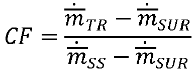
- if the load change ÄL to the load L is positive. This corresponds to acceleration scheduling during load acceptance i.e. the correction factor CF is an acceleration correction factor ACF.
- Particularly, there are two special cases to consider if the load change ÄL to the load L is positive.
- In the first special case, further acceleration is not possible:

- In the second special case, free acceleration is possible:

- In one example, the correction
factor determination unit 620 is arranged to determine the correction factor CF by calculating the correction factor CF according to:


- In one example, the correction
factor determination unit 620 is arranged to determine the correction factor CF by calculating the correction factor CF according to:
- Particularly, there are two special cases to consider if the load change ÄL to the load L is negative.
- In the first special case, further deceleration is not possible:

- In the second special case, free deceleration is possible:

- In one example, the correction
factor determination unit 620 is arranged to determine the correction factor CF by calculating the correction factor CF according to:


- In one example, the
controller 600 is arranged to, responsive to the load change ÄL to the load L, control thecompressor 101 to provide air to thecombustor 102 at the new air mass flow rate


- In one example, the acceleration/
deceleration schedule unit 630 is arranged to determine the rate of change of the rotational speed
deceleration schedule unit 630 is arranged to determine the rate of change of the rotational speed
n , for example, as described below with reference toFigures 10 and/or 12. In one example, this rate of change comprises and/or is an estimated acceleration/deceleration demand of thecompressor 101. In one example, the acceleration/deceleration schedule unit 630 is arranged to receive the rotational speedn from thegas turbine 100. In one example, the acceleration/deceleration schedule unit 630 is arranged provide the determined rate of change of the rotational speed
compressor 101, to themultiplication unit 640. - In one example, the
controller 600 is arranged to control thecompressor 101 to provide air to thecombustor 102 at the new air mass flow rate


- In one example, the
multiplication unit 640 is arranged to multiply (i.e. calculate the product of) the determined correction factor CF provided by the correctionfactor determination unit 620 and the estimated acceleration/deceleration demand of thecompressor 101 provided by the acceleration/deceleration schedule unit 630, thereby providing a corrected acceleration/deceleration demand of thecompressor 101. In one example, themultiplication unit 640 is arranged to provide the product of the determined correction factor CF and the determined rate of change of the rotational speed
summation unit 660. - In one example, the
controller 600 is arranged to control thecompressor 101 to provide air to thecombustor 102 at the new fuel mass flow rate


- In one example, the acceleration/
deceleration determination unit 650 is arranged to determine the rate of change of the rotational speed
n (i.e. an actual value rather than an estimate, for example). In one example, the acceleration/deceleration determination unit 650 is arranged to receive the rotational speedn from thegas turbine 100. In one example, the acceleration/deceleration determination unit 650 is arranged to provide the determined rate of change of the rotational speed
summation unit 660. - In one example, the
summation unit 660 is arranged to sum the determined rate of change of the rotational speed
deceleration determination unit 650 and the product of the determined correction factor CF and the determined rate of change of the rotational speed
multiplication unit 640, thereby providing an acceleration/deceleration error of thecompressor 101 as a difference between the corrected acceleration/deceleration demand and the actual value provided by the acceleration/deceleration determination unit 650. In one example, thesummation unit 660 is arranged to provide this sum (i.e. the acceleration/deceleration error of the compressor 101) to thePI controller 670. - In one example, the
controller 600 is arranged to, responsive to the load change ÄL to the load L, control thecompressor 101 to provide air to thecombustor 102 at the new air mass flow rate


- In one example, the
controller 600 is arranged to, responsive to the load change ÄL to the load L, control the fuel supply means 127 to supply fuel at the fuel mass flow rate mtotαl to thecombustor 102. In one example, thecontroller 600 is arranged to determine the fuel mass flow rate mtotal corresponding with the new air mass flow rate
- In one example, the
PI controller 670 is arranged to determine the new air mass flow rate
summation unit 660, of the determined rate of change of the rotational speed

PI controller 670 is arranged to provide the determined new total fuel mass flow rate mtotal to theselector 680. - In one example, the
PI controller 670 is arranged to determine the fuel mass flow rate mtotαl to be supplied by the fuel supply means 127 to thecombustor 102 based, at least in part, on the sum, provided by thesummation unit 660, of the determined rate of change of the rotational speed

PI controller 670 is arranged to provide the determined fuel mass flow rate mtotal to theselector 680. - In one example, the
selector 680 is arranged to provide the determined new total fuel mass flow rate mtotal to thegas turbine 100, for example to thecompressor 101, thereby controlling thegas turbine 100 according to the determined new air mass flow rate
selector 680 is arranged to provide the determined new total fuel mass flow rate mtotal to the real-time model unit 610, thereby feeding this value back into the real-time model. - In one example, the
selector 680 is arranged to provide the determined fuel mass flow rate mtotal to thegas turbine 100, for example to the fuel supply means 127, thereby controlling thegas turbine 100 according to the determined fuel mass flow rate mtotal. In one example, theselector 680 is arranged to provide the determined fuel mass flow rate mtotal to the real-time model unit 610, thereby feeding this value back into the real-time model. - At S601, the real-
time model unit 610 receives the rotational speedn from thegas turbine 100. More generally, at S601, the real-time model unit 610 receives all available measurements from thegas turbine 100, for example speeds, pressures and/or temperatures at different engine stations. - At S602, the real-
time model unit 610 determines the estimate of the new air mass flow rate
n , as described above, and provides the estimate of the new air mass flow rate
factor determination unit 620. - At S603, the correction
factor determination unit 620 receives the rotational speedn from thegas turbine 100. - At S604, the correction
factor determination unit 620 determines the correction factor CF based, at least in part, on the received rotational speedn and the estimate of the new air mass flow rate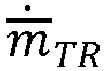
time model unit 610, as described above, and provides the determined correction factor CF to themultiplication unit 640. - At S605, the acceleration/
deceleration schedule unit 630 receives the rotational speedn from thegas turbine 100. - At S606, the acceleration/
deceleration schedule unit 630 determines the rate of change of the rotational speed
n as an estimated acceleration/deceleration demand of thecompressor 101 and provides an allowable, for example acceptable, permissible, permitted, tolerable or sustainable, acceleration/deceleration demand to themultiplication unit 640. - At S607, the
multiplication unit 640 multiplies (i.e. calculates the product of) the determined correction factor CF provided by the correctionfactor determination unit 620 and the allowable acceleration/deceleration demand of thecompressor 101 provided by the acceleration/deceleration schedule unit 630, thereby providing the corrected allowable acceleration/deceleration demand of thecompressor 101. Themultiplication unit 640 provides the corrected allowable acceleration/deceleration demand of thecompressor 101 to thesummation unit 660. - At S608, the acceleration/
deceleration determination unit 650 receives the rotational speedn from thegas turbine 100. - At S609, the acceleration/
deceleration determination unit 650 determines the rate of change of the rotational speed
n (i.e. an actual value rather than an estimate, for example) and provides the determined rate of change of the rotational speed
summation unit 660. - At S610, the
summation unit 660 sums the determined rate of change of the rotational speed
deceleration determination unit 650 and the corrected acceleration/deceleration demand of thecompressor 101, thereby providing an acceleration/deceleration error of thecompressor 101 as a difference between the corrected acceleration/deceleration demand and the actual value provided by the acceleration/deceleration determination unit 650. Thesummation unit 660 provides this acceleration/deceleration error of thecompressor 101 to thePI controller 670. - At S611, the
PI controller 670 determines the new fuel mass flow rate mtotal based, at least in part, on the acceleration/deceleration error of thecompressor 101, as described above. In this example, thePI controller 670 determines the fuel mass flow rate mtotal to be supplied by the fuel supply means 127 to thecombustor 102. ThePI controller 670 provides the fuel mass flow rate mtotal to theselector 680. - At S612, the
selector 680 provides the determined new fuel mass flow rate to thegas turbine 100, thereby controlling thegas turbine 100 according to the determined new air mass flow rate
selector 680 provides the determined fuel mass flow rate mtotαl to thegas turbine 100, for example to the fuel supply means 127, thereby controlling thegas turbine 100 according to the determined fuel mass flow rate mtotal. More generally, at S612, theselector 680 may provide the total, the pilot and/or the main fuel demands to thegas turbine 100. Theselector 680 may additionally provide other and/or all demands, for example variable guide vane (VGV) demand and/or blow off valve (BOV) demand, to thegas turbine 100. - At S613, the
selector 680 provides the determined fuel mass flow rate mtotαl to the real-time model unit 610, thereby feeding this value back into the real-time model. More generally, at S613, theselector 680 may provide the total, the pilot and/or the main fuel demands to the real-time model unit 610. Theselector 680 may additionally provide other and/or all demands, for example variable guide vane (VGV) demand and/or blow off valve (BOV) demand, to the real-time model unit 610. -
Figure 7 shows a schematic view of a method of controlling thegas turbine 100 according to an example not forming part of the claimed invention. - The method is of controlling the
gas turbine 100 arranged to supply the load L, thegas turbine 100 comprising thecompressor 101 arranged to operate at a rotational speedn , acombustor 102 and a fuel supply means 127 comprising a first fuel supply means and a second fuel supply means, wherein thecompressor 101 is arranged to provide air to thecombustor 102 at a steady state air mass flow rate
combustor 102. - At S701, responsive to the load change ÄL to the load L, the
compressor 101 is controlled to provide air to thecombustor 102 at the new air mass flow rate


- Optionally, the method comprises repeating S701, for example successively, periodically, regularly and/or irregularly, responsive to subsequent load changes ÄL. The method may include any of the steps described herein.
-
Figure 8 shows a schematic view of a method of controlling thegas turbine 100 according to an example not forming part of the claimed invention. Particularly,Figure 8 shows a pressure map for thegas turbine 100 in which a compressor pressure ratio PR is plotted as a function of compressor air mass flow rate. The compressor pressure ratio PR is the ratio of the compressor outlet pressure to the compressor inlet pressure.
- The pressure map includes a running line for a steady state air mass flow rate
 . The pressure map includes the first, lower threshold

burner flame 30, at lower compressor pressure ratios PR than the running line for the same compressor air mass flow rateand which diverges away from the running line at higher compressor air mass flow rates . The pressure map includes the second, upper threshold

compressor 101, at higher compressor pressure ratios PR than the running line for the same compressor air mass flow rateand which diverges away from the running line at higher compressor air mass flow rates before converging theretowards. The pressure map includes a third threshold





n K-1,n K andn K+1, corresponding to three adjacent rotational speedsn , are labelled. -
Figure 9 shows a schematic view of a method of controlling thegas turbine 100 according to an example not forming part of the claimed invention. Particularly,Figure 9 shows an example of the pressure map, as described with reference toFigure 8 , for acceleration scheduling during load acceptance due to a positive transient load change ÄL. As shown by the curved arrow inFigure 9 , during load acceptance due to the positive transient load change ÄL, thegas turbine 100 is controlled to move from the initial steady state air mass flow rate


gas turbine 100 may be controlled to operate closer to the second threshold
gas turbine 100 to accept larger positive load changes ÄL without surging. -
Figure 10 shows a schematic view of a method of controlling a gas turbine according to an example not forming part of the claimed invention. Particularly,Figure 10 shows a graph of a nominal acceleration schedule in which rate of change of the rotational speed
n . The acceleration slowly increases as a function of rotational speedn and spikes to a maximum of approximately 3,200 at a rotational speedn of approximately 13,000 before decreasing at higher speeds. A normal operating range of the rotational speedn is from approximately 11,000 to 13,000, in this example. -
Figure 11 shows a schematic view of a method of controlling thegas turbine 100 according to an example not forming part of the claimed invention. Particularly,Figure 11 shows an example of the compressor pressure ratio map, as described with reference toFigure 8 , for deceleration scheduling during load rejection due to a negative transient load change ÄL. As shown by the curved arrow inFigure 9 , during load rejection due to the negative transient load change ÄL, thegas turbine 100 is controlled to move from the initial steady state air mass flow rate


gas turbine 100 may be controlled to operate closer to the first threshold
gas turbine 100 to accept larger negative load changes ÄL without loss of flame. -
Figure 12 shows a schematic view of a method of controlling a gas turbine according to an example not forming part of the claimed invention. Particularly,Figure 12 shows a graph of a nominal deceleration schedule in which rate of change of the rotational speed
n . The acceleration is constant as a function of rotational speedn to approximately 9,000 before decreasing at higher speeds, in this example. -
Figure 13 shows a schematic view of acontroller 700 according to an exemplary embodiment. Particularly,Figure 13 shows a schematic view of thecontroller 700 communicatively coupled to thegas turbine 100. - In one example, the
controller 700 comprises thecontroller 600 or vice versa. - The
controller 700 is for thegas turbine 100. Thegas turbine 100 comprises thecompressor 101 arranged to operate at a rotational speedn , thecombustor 102 and the fuel supply means 127 comprising the first fuel supply means and the second fuel supply means, wherein thecompressor 101 is arranged to provide air to thecombustor 102 at a steady state air mass flow rate
combustor 102. Thecontroller 700 is arranged to, responsive to a load change ÄL to the load L, control the fuel supply means 127 to supply a proportion Z of the fuel mass flow rate mtotal as a fuel mass flow rate ṁfuel_pilot via the first fuel supply means based, at least in part, on a combustor mass flow rate ṁt. - It should be understood that the combustor mass flow rate ṁt is a sum of an air mass flow rate(for example, the steady state air mass flow rate


combustor 102 by thecompressor 101 and supplied by the fuel supply means 127, respectively, for a current time step t. The current time step t may be in a range from 1 ms to 100 ms, preferably from 10 to 50 ms. - In this example, the
controller 700 comprises a real-time model unit 710, a one timestep delay unit 790, an acceleration/deceleration schedule unit 730, amultiplication unit 740 and aselector unit 780. Other arrangements are possible. - The real-
time model unit 710, the acceleration/deceleration schedule unit 730, themultiplication unit 740 and/or theselector unit 780 may comprise and/or be as described above with respect to the real-time model unit 610, the acceleration/deceleration schedule unit 630, themultiplication unit 640 and/or theselector unit 680, respectively. - In one example, the real-
time model unit 710 is arranged to determine the combustor mass flow rate mt. In one example, the real-time model unit 710 is arranged to determine the combustor mass flow rate mt based, at least in part, on a real-time model of thegas turbine 100. In one example, the real-time model unit 710 is arranged to determine the combustor mass flow rate mt based, at least in part, on the rotational speedn . In one example, the real-time model unit 710 is arranged to receive the rotational speedn from thegas turbine 100. In one example, the real-time model unit 710 is arranged to provide the determined combustor mass flow rate mt to the timestep delay unit 790 and/or to themultiplication unit 740. - In one example, the real-
time model unit 710 comprises a real-time (also known as a dynamic) model of thegas turbine 100 described mathematically by a set of nonlinear differential equations, as described above with respect to the real-time model unit 610:
- Measurements (also known as sensed parameters) may be taken on various quantities in the
gas turbine 100. These sensed parameters may be related to the states, inputs and parameters according to the general algebraic expression:
- Where, in general, vector y comprises measurable and non-measurable parameters. These above equations for the state coordinate vector ẋ and the vector y may be general enough to provide a starting point to describe the
gas turbine 100 with respect to control design and state estimation. - After an accurate model is developed for the generic baseline, this gas turbine model may be expanded to include data representing the deteriorated gas turbine 100 (i.e. following use of the
gas turbine 100, for example following commissioning and/or extended use thereof). Deterioration effects may include efficiency changes, area changes, pressure drops, as well as flow changes and disturbances due to bleed effects, for example. Typically, the two quantities of capacity and efficiency may be used to model changes in operation of thegas turbine 100 resulting in decreased energy conversion efficiency or component flow characteristics. - In one example, the real-time model is as described in
WO 2015/117791 and/orWO 2017/198528 . - In one example, the
controller 700 is arranged to control the proportion Z of the fuel mass flow rate mtotal as the fuel mass flow rate ṁfuel_pilot supplied via the first fuel supply means is based, at least in part, on a previous combustor mass flow rate ṁ t-1 supplied in a previous time step t - 1. In one example, the previous time step t - 1 is one (i.e. only, a single or exactly one) time step preceding the current time step t. - In one example, the time
step delay unit 790 is arranged to determine the previous combustor mass flow rate ṁ t-1 supplied in a previous time step t - 1, for example corresponding to the determined combustor mass flow rate mt for the current time step t received from the real-time model unit 710. In one example, the timestep delay unit 790 is arranged to obtain the previous combustor mass flow rate ṁ t-1, for example from a memory block, for example a look-up table or a map. - In one example, the
controller 700 is arranged to control the proportion Z of the fuel mass flow rate mtotal as the fuel mass flow rate ṁfuel_pilot supplied via the first fuel supply means based, at least in part, on the previous combustor mass flow rate ṁ T-1 supplied in the previous time step t - 1, wherein the previous combustor mass flow rate ṁ t-1 is provided from a set thereof. - In one example, the time
step delay unit 790 is arranged to obtain the previous combustor mass flow rate ṁ t-1 for the previous time step t - 1, for example from a memory block, for example a look-up table or a map. In one example, the timestep delay unit 790 is arranged to provide the combustor mass flow rate ṁt to the acceleration/deceleration schedule unit 730 which contains the memory block, for example a look-up table or a map. - In one example, the
controller 700 is arranged to, responsive to the load change ÄL to the load L, control the fuel supply means 127 to supply the proportion Z of the fuel mass flow rate mtotal as the fuel mass flow rate ṁfuel_pilot via the first fuel supply means based, at least in part, on an estimated acceleration/deceleration first fuel (also known as pilot) demand obtained from a acceleration/deceleration schedule as a function of the combustor mass flow rate ṁ t-1 for the previous time step t - 1, for example from an acceleration/deceleration schedule thereof. The estimated acceleration/deceleration first fuel demand may be determined generally from a ratio of the fuel mass flow rate ṁfuel_pilot to the combustor mass flow rate m:
- In one example, the acceleration/
deceleration schedule unit 730 is arranged to determine the estimated acceleration/deceleration first fuel demand based, at least in part, on the combustor mass flow rate ṁ t-1 for the previous time step t - 1 provided by thetime step unit 790. In one example, the acceleration/deceleration schedule unit 730 is arranged to determine the estimated acceleration/deceleration first fuel demand as a ratio of the fuel mass flow rate ṁfuel_pilot to the combustor mass flow rate ṁ t-1 for the previous time step t - 1, for example from an acceleration/deceleration schedule thereof. In one example, the acceleration/deceleration schedule unit 730 is arranged to provide the estimated acceleration/deceleration first fuel demand to themultiplication unit 740. - In one example, the
multiplication unit 740 is arranged to multiply (i.e. calculate the product of) the combustor mass flow rate ṁt for the current time step t provided by the real-time model unit 710 and the estimated acceleration/deceleration first fuel demand provided (i.e. determined from the combustor mass flow rate ṁ t-1 for the previous time step t - 1) by the acceleration/deceleration schedule unit 730, thereby providing a corrected acceleration/deceleration first fuel demand. The corrected acceleration/deceleration first fuel demand may be thus expressed as:
- In one example, the
multiplication unit 740 is arranged to provide the corrected acceleration/deceleration first fuel demand to theselector 780. - In one example, the
selector 780 is arranged to provide the corrected acceleration/deceleration first fuel demand to thegas turbine 100, for example to the fuel supply means 127, thereby controlling thegas turbine 100 according to the corrected acceleration/deceleration first fuel demand schedule. In one example, theselector 780 is arranged to provide the corrected acceleration/deceleration first fuel demand to the real-time model unit 710 (thereby feeding this value back into the real-time model) and to thegas turbine 100. - According to the invention, the proportion Z of the fuel mass flow rate mtotal as the fuel mass flow rate ṁfuel_pilot supplied via the first fuel supply means is within a range between a first pilot threshold ṁLBO and a second pilot threshold ṁTT.
- In one example, the first pilot threshold ṁLBO corresponds with loss of a pilot flame of the
combustor 102. - In one example, the second pilot threshold ṁTT corresponds with overheating of a burner of the
combustor 102. - According to the invention, the first pilot threshold ṁLBO is pre-determined for the
gas turbine 100, for example according to data obtained therefrom, included in the real-time model and/or in the acceleration/deceleration schedule, as described above. - According to the invention, the second pilot threshold ṁTT is pre-determined for the
gas turbine 100, for example according to data obtained therefrom, included in the real-time model and/or in the acceleration/deceleration schedule, as described above. - In one example, the proportion Z of the fuel mass flow rate mtotal as the fuel mass flow rate ṁfuel_pilot supplied via the first fuel supply means is below the first pilot threshold ṁLBO for at most a predetermined first duration, for example in a range of 1 to 100 time steps, preferably in a range from 1 to 10 time steps, more preferably in a range from 1 to 5 time steps, for example 3 time steps. Temporary deviations below the first pilot threshold ṁLBO may be acceptable. The time step may be in a range from 1 ms to 100 ms, preferably from 10 to 50 ms.
- In one example, the proportion Z of the fuel mass flow rate mtotal as the fuel mass flow rate ṁfuel_pilot supplied via the first fuel supply means is above the second pilot threshold ṁTT for at most a predetermined second duration, for example in a range of 1 to 100 time steps, preferably in a range from 1 to 10 time steps, more preferably in a range from 1 to 5 time steps, for example 3 time steps. Temporary deviations above the second pilot threshold ṁTT may be acceptable. The time step may be in a range from 1 ms to 100 ms, preferably from 10 to 50 ms.
- In one example, controlling the proportion Z of the fuel mass flow rate mtotal as the fuel mass flow rate ṁfuel_pilot supplied via the first fuel supply means comprises decreasing the proportion Z if the load change ÄL to the load L is positive.
- In one example, controlling the proportion Z of the fuel mass flow rate mtotal as the fuel mass flow rate ṁfuel_pilot supplied via the first fuel supply means comprises increasing the proportion Z if the load change ÄL to the load L is negative.
- At S1301, the real-
time model unit 710 receives all available measurements from thegas turbine 100, for example speeds, pressures and/or temperatures at different engine stations. - At S1302, the real-
time model unit 710 determines the combustor mass flow rate ṁt based, at least in part, the fuel mass flow rate ṁtotal for the current time step t, as described above, and provides the combustor mass flow rate mt to the to thetime step unit 790. - At S1303, the
time step unit 790 obtains the previous combustor mass flow rate ṁ t-1 for the previous time step t - 1, for example from a memory block for example a look-up table or a map, and provides the previous combustor mass flow rate ṁ t-1 for the previous time step t - 1 to the acceleration/deceleration schedule unit 730. - At S1304, the acceleration/
deceleration schedule unit 730 determines the estimated acceleration/deceleration first fuel demand based, at least in part, on the combustor mass flow rate ṁ t-1 for the previous time step t - 1 provided by thetime step unit 790, from an acceleration/deceleration schedule thereof, and provides the estimated acceleration/deceleration first fuel demand to themultiplication unit 740. - At S1305, the real-
time model unit 710 provides the combustor mass flow rate mt to themultiplication unit 740. - At S1306, the
multiplication unit 740 multiplies (i.e. calculates the product of) the combustor mass flow rate ṁt for the current time step t provided by the real-time model unit 710 and the estimated acceleration/deceleration first fuel demand provided (i.e. determined from the combustor mass flow rate ṁ t-1 for the previous time step t - 1) by the acceleration/deceleration schedule unit 730, thereby providing the corrected acceleration/deceleration first fuel demand expressed as:
- The
multiplication unit 740 provides the corrected acceleration/deceleration first fuel demand to theselector 780. - At S1307, the
selector 780 provides the corrected acceleration/deceleration first fuel demand to thegas turbine 100, for example to the fuel supply means 127, thereby controlling thegas turbine 100 according to the corrected acceleration/deceleration first fuel demand. More generally, at S1307, theselector 780 may provide the total, the pilot and/or the main fuel demands to thegas turbine 100. Theselector 780 may additionally provide other and/or all demands, for example variable guide vane (VGV) demand and/or blow off valve (BOV) demand, to thegas turbine 100. - At S1308, the
selector 780 provides the corrected acceleration/deceleration first fuel demand to the real-time model unit 710, thereby feeding this value back into the real-time model. More generally, at S1308, theselector 780 may provide the total, the pilot and/or the main fuel demands to the real-time model unit 710. Theselector 780 may additionally provide other and/or all demands, for example variable guide vane (VGV) demand and/or blow off valve (BOV) demand, to the real-time model unit 710. -
Figure 14 shows a schematic view of a method of controlling thegas turbine 100 according to an exemplary embodiment. - The method is of controlling the
gas turbine 100 arranged to supply the load L, thegas turbine 100 comprising thecompressor 101 arranged to operate at a rotational speedn , acombustor 102 and a fuel supply means 127 comprising a first fuel supply means and a second fuel supply means, wherein thecompressor 101 is arranged to provide air to thecombustor 102 at a steady state air mass flow rate
combustor 102. - At S1401, responsive to a load change ÄL to the load L, the fuel supply means 127 is controlled to supply the proportion Z of the fuel mass flow rate mtotal as the fuel mass flow rate ṁfuel_pilot via the first fuel supply means based, at least in part, on the combustor mass flow rate ṁt.
- Optionally, the method comprises repeating S1401, for example successively, periodically, regularly and/or irregularly, responsive to subsequent load changes ÄL.
- The method may comprise any of the method steps described herein, for example including as described with respect to
Figure 7 . -
Figure 15 shows a schematic view of a method of controlling thegas turbine 100 according to an exemplary embodiment. Particularly,Figure 15 shows a pilot split map (also known as an acceleration/deceleration pilot demand schedule) for thegas turbine 100 in which a pilot fuel demand split is plotted as a function of combustor mass flow rate ṁt. The pilot fuel demand split is the ratio of the fuel mass flow rate ṁfuel_pilot to the combustor mass flow rate m:
- The pilot split map includes a running line for a steady state combustor mass flow rate ṁt, for which the pilot fuel demand split is approximately inversely proportional to the combustor mass flow rate m. The fuel map includes the first, lower pilot threshold ṁLBO, which is the lean blow out (LBO) limit, corresponding with loss of the pilot flame, at lower pilot fuel demand splits than the running line for the same combustor mass flow rate ṁ and which converges towards the running line at higher combustor mass flow rate m. The pressure map includes the second, upper pilot threshold ṁTT, which is the tip temperature limit, corresponding with overheating of the burner, at higher pilot fuel demand splits than the running line for the same combustor mass flow rate ṁ and which converges towards the running line at higher combustor mass flow rate m.
-
Figure 16 shows a schematic view of a method of controlling thegas turbine 100 according to an exemplary embodiment. Particularly,Figure 16 shows an example of the pilot split map, as described with reference toFigure 15 , for acceleration scheduling during load acceptance due to a positive transient load change ÄL. As shown by the curved arrow inFigure 16 , during load acceptance due to the positive transient load change ÄL, thegas turbine 100 is controlled to move from the initial pilot fuel demand split on the running line, corresponding with the previous combustor mass flow rate ṁ t-1 supplied in a previous time step t - 1, to operate at the new pilot fuel demand split between the steady state combustor mass flow rate ṁ and the first pilot threshold ṁLBO (i.e. a lower pilot fuel demand split), before returning to operate on the steady state combustor mass flow rate m running line, following load acceptance. In this way, thegas turbine 100 may be controlled to operate closer to the first pilot threshold ṁLBO, allowing thegas turbine 100 to accept larger positive load changes ÄL without loss of pilot flame. -
Figure 17 shows a schematic view of a method of controlling thegas turbine 100 according to an exemplary embodiment. Particularly,Figure 17 shows an example of the pilot split map, as described with reference toFigure 15 , for deceleration scheduling during load rejection due to a negative transient load change ÄL. As shown by the curved arrow inFigure 16 , during load rejection due to the negative transient load change ÄL, thegas turbine 100 is controlled to move from the initial pilot fuel demand split on the running line, corresponding with the previous combustor mass flow rate ṁ t-1 supplied in a previous time step t - 1, to operate at the new pilot fuel demand split between the steady state combustor mass flow rate ṁ and the second pilot threshold ṁTT (i.e. a higher pilot fuel demand split), before returning to operate on the steady state combustor mass flow rate m running line, following load rejection. In this way, thegas turbine 100 may be controlled to operate closer to the second pilot threshold ṁTT, allowing thegas turbine 100 to accept larger negative load changes ÄL without overheating of the pilot nozzle.
Claims (12)
- A method of controlling a gas turbine (100) arranged to supply a load L, the gas turbine (100) comprising a compressor (101) arranged to operate at a rotational speed
n , a combustor (102) and a fuel supply means (127) comprising a first fuel supply means and a second fuel supply means, wherein the compressor (101) is arranged to provide air to the combustor (102) at a steady state air mass flow rate responsive to the load change AL to the load L, controlling the fuel supply means (127) to supply a proportion Z of the fuel mass flow rate mtotal as a fuel mass flow rate ṁfuel_pilot via the first fuel supply means (127) based, at least in part, on a combustor mass flow rate ṁt (S1401), characterised in thatthe proportion Z of the fuel mass flow rate mtotal as the fuel mass flow rate ṁfuel_pilot supplied via the first fuel supply means is within a range between a first pilot threshold ṁLB0 and a second pilot threshold ṁTT andthe first pilot threshold ṁLBO is pre-determined for the gas turbine (100) and the second pilot threshold ṁTT is pre-determined for the gas turbine (100).
 - The method according to claim 1, wherein controlling the proportion Z of the fuel mass flow rate mtotal as the fuel mass flow rate ṁfuel_pilot supplied via the first fuel supply means is based, at least in part, on a previous combustor mass flow rate ṁ t-1 supplied in a previous time step t - 1.
- The method according to claim 2, wherein controlling the proportion Z of the fuel mass flow rate mtotal as the fuel mass flow rate ṁfuel_pilot supplied via the first fuel supply means is based, at least in part, on the previous combustor mass flow rate ṁ T-1 supplied in the previous time step t - 1, wherein the previous combustor mass flow rate ṁ t-1 is provided from a set thereof.
- The method according to any one of claims 1-3, wherein the first pilot threshold ṁLBO corresponds with corresponding with loss of a pilot flame of the combustor (102).
- The method according to any one of claims 1-4, wherein the second pilot threshold ṁTT corresponds with overheating of a burner of the combustor (102).
- The method according to any of one of claims 1-5, wherein the proportion Z of the fuel mass flow rate mtotal as the fuel mass flow rate ṁfuel_pilot supplied via the first fuel supply means is below the first pilot threshold ṁLBO for at most a predetermined first duration.
- The method according to any of any one of claims 1-5, wherein the proportion Z of the fuel mass flow rate mtotal as the fuel mass flow rate ṁfuel_pilot supplied via the first fuel supply means is above the second pilot threshold ṁTT for at most a predetermined second duration.
- The method according to any previous claim, wherein controlling the proportion Z of the fuel mass flow rate mtotal as the fuel mass flow rate ṁfuel_pilot supplied via the first fuel supply means comprises decreasing the proportion Z if the load change AL to the load L is positive.
- The method according to any previous claim, wherein controlling the proportion Z of the fuel mass flow rate mtotal as the fuel mass flow rate ṁfuel_pilot supplied via the first fuel supply means comprises increasing the proportion Z if the load change AL to the load L is negative.
- A controller (700) for a gas turbine (100), the gas turbine (100) comprising a compressor (101) arranged to operate at a rotational speed
n , a combustor (102) and a fuel supply means (127) comprising a first fuel supply means and a second fuel supply means, wherein the compressor (101) is arranged to provide air to the combustor (102) at a steady state air mass flow rate responsive to a load change AL to the load L, control the fuel supply means to supply a proportion Z of the fuel mass flow rate mtotal as a fuel mass flow rate ṁfuel_pilot via the first fuel supply means based, at least in part, on a combustor mass flow rate ṁt characterised in thatthe proportion Z of the fuel mass flow rate mtotal as the fuel mass flow rate ṁfuel_pilot supplied via the first fuel supply means is within a range between a first pilot threshold ṁLBO and a second pilot threshold ṁTT andthe first pilot threshold ṁLBO is pre-determined for the gas turbine (100) and the second pilot threshold ṁTT is pre-determined for the gas turbine (100).
 - A gas turbine (100) comprising a compressor (101) arranged to operate at a rotational speed
n , a combustor (102) and a fuel supply means (127) comprising a first fuel supply means and a second fuel supply means, wherein the compressor (101) is arranged to provide air to the combustor (102) at a steady state air mass flow rate
- A tangible non-transient computer-readable storage medium is provided having recorded thereon instructions which when implemented by a controller (700) for a gas turbine (100), the gas turbine (100) comprising a compressor (101) arranged to operate at a rotational speed
n , a combustor (102) and a fuel supply means (127) comprising a first fuel supply means and a second fuel supply means, wherein the compressor (101) is arranged to provide air to the combustor (102) at a steady state air mass flow rate
Applications Claiming Priority (2)
| Application Number | Priority Date | Filing Date | Title |
|---|---|---|---|
| EP18158436.8A EP3530913A1 (en) | 2018-02-23 | 2018-02-23 | Controller and method |
| PCT/EP2019/053575 WO2019162167A1 (en) | 2018-02-23 | 2019-02-13 | Controller and method |
Publications (2)
| Publication Number | Publication Date |
|---|---|
| EP3755896A1 EP3755896A1 (en) | 2020-12-30 |
| EP3755896B1 true EP3755896B1 (en) | 2023-05-17 |
Family
ID=61283012
Family Applications (2)
| Application Number | Title | Priority Date | Filing Date |
|---|---|---|---|
| EP18158436.8A Withdrawn EP3530913A1 (en) | 2018-02-23 | 2018-02-23 | Controller and method |
| EP19707286.1A Active EP3755896B1 (en) | 2018-02-23 | 2019-02-13 | Controller and method |
Family Applications Before (1)
| Application Number | Title | Priority Date | Filing Date |
|---|---|---|---|
| EP18158436.8A Withdrawn EP3530913A1 (en) | 2018-02-23 | 2018-02-23 | Controller and method |
Country Status (6)
| Country | Link |
|---|---|
| US (1) | US11655769B2 (en) |
| EP (2) | EP3530913A1 (en) |
| CN (1) | CN111742129B (en) |
| CA (1) | CA3089687C (en) |
| RU (1) | RU2754621C1 (en) |
| WO (1) | WO2019162167A1 (en) |
Families Citing this family (4)
| Publication number | Priority date | Publication date | Assignee | Title |
|---|---|---|---|---|
| US12025060B2 (en) * | 2021-05-19 | 2024-07-02 | Pratt & Whitney Canada Corp. | Method and system for operating an engine to prevent high power engine surges |
| US11739699B2 (en) * | 2021-11-08 | 2023-08-29 | Pratt & Whitney Canada Corp. | Method of controlling the geometrical configuration of a variable geometry element in a gas turbine engine compressor stage |
| EP4234922A1 (en) * | 2022-02-25 | 2023-08-30 | Siemens Gamesa Renewable Energy A/S | Method of operating a wind turbine |
| CN119616676B (en) * | 2023-09-13 | 2025-11-25 | 中国航发商用航空发动机有限责任公司 | Gas turbine engine, fuel supply method, supply system and medium |
Family Cites Families (18)
| Publication number | Priority date | Publication date | Assignee | Title |
|---|---|---|---|---|
| JPH07189746A (en) | 1993-12-28 | 1995-07-28 | Hitachi Ltd | Control method for gas turbine combustor |
| US5896736A (en) * | 1997-03-06 | 1999-04-27 | General Electric Company | Load rejection rapid acting fuel-air controller for gas turbine |
| US6095793A (en) * | 1998-09-18 | 2000-08-01 | Woodward Governor Company | Dynamic control system and method for catalytic combustion process and gas turbine engine utilizing same |
| DE102004005476A1 (en) * | 2003-02-11 | 2004-12-09 | Alstom Technology Ltd | Process for operating a gas turbine group |
| RU2258149C1 (en) | 2004-03-12 | 2005-08-10 | Федеральное государственное унитарное предприятие "Московское машиностроительное производственное предприятие "САЛЮТ" (ФГУП "ММПП "САЛЮТ") | Method to control fuel delivery into afterburner |
| JP4119909B2 (en) | 2005-09-14 | 2008-07-16 | 三菱重工業株式会社 | Combustion control device for gas turbine |
| EP1944547A1 (en) | 2007-01-15 | 2008-07-16 | Siemens Aktiengesellschaft | Method of controlling a fuel split |
| WO2011042037A1 (en) * | 2009-10-09 | 2011-04-14 | Siemens Aktiengesellschaft | Combustion apparatus |
| EP2442031A1 (en) | 2010-10-13 | 2012-04-18 | Siemens Aktiengesellschaft | Combustion device with pulsed fuel split |
| EP2568145B1 (en) * | 2011-09-08 | 2018-03-21 | Ansaldo Energia IP UK Limited | Gas turbine controller and a method for controlling a gas turbine |
| US9803560B2 (en) * | 2013-03-15 | 2017-10-31 | Ansaldo Energia Ip Uk Limited | Dynamic tuning of a gas turbine engine to detect and prevent lean blowout |
| EP2905666A1 (en) | 2014-02-07 | 2015-08-12 | Siemens Aktiengesellschaft | Estimation of health parameters in industrial gas turbines |
| EP2952811A1 (en) | 2014-06-02 | 2015-12-09 | Siemens Aktiengesellschaft | Method and device to control a fuel split in a combustion device |
| JP6332747B2 (en) | 2014-08-06 | 2018-05-30 | 三菱日立パワーシステムズ株式会社 | Flow ratio calculation device, control device including the same, gas turbine plant including the control device, flow ratio calculation method, and fuel system control method |
| AU2016254323B2 (en) * | 2015-04-30 | 2019-11-28 | Nuovo Pignone Tecnologie Srl | Ultra-low NOx emission gas turbine engine in mechanical drive applications |
| EP3246547A1 (en) | 2016-05-18 | 2017-11-22 | Siemens Aktiengesellschaft | Controlling a gas turbine considering a sensor failure |
| EP3267107B1 (en) | 2016-07-08 | 2021-03-17 | Ansaldo Energia IP UK Limited | Method of controlling a gas turbine assembly |
| US20180216484A1 (en) * | 2017-01-31 | 2018-08-02 | General Electric Company | Systems and methods to detect a fluid induced instability condition in a turbomachine |
-
2018
- 2018-02-23 EP EP18158436.8A patent/EP3530913A1/en not_active Withdrawn
-
2019
- 2019-02-13 RU RU2020127714A patent/RU2754621C1/en active
- 2019-02-13 CN CN201980014904.0A patent/CN111742129B/en active Active
- 2019-02-13 US US16/968,585 patent/US11655769B2/en active Active
- 2019-02-13 EP EP19707286.1A patent/EP3755896B1/en active Active
- 2019-02-13 CA CA3089687A patent/CA3089687C/en active Active
- 2019-02-13 WO PCT/EP2019/053575 patent/WO2019162167A1/en not_active Ceased
Also Published As
| Publication number | Publication date |
|---|---|
| CA3089687A1 (en) | 2019-08-29 |
| WO2019162167A1 (en) | 2019-08-29 |
| CA3089687C (en) | 2022-08-09 |
| CN111742129A (en) | 2020-10-02 |
| US11655769B2 (en) | 2023-05-23 |
| EP3755896A1 (en) | 2020-12-30 |
| US20210040900A1 (en) | 2021-02-11 |
| CN111742129B (en) | 2024-01-30 |
| RU2754621C1 (en) | 2021-09-06 |
| EP3530913A1 (en) | 2019-08-28 |
Similar Documents
| Publication | Publication Date | Title |
|---|---|---|
| EP3755895B1 (en) | Controller and method | |
| EP3755896B1 (en) | Controller and method | |
| EP2650504B1 (en) | Method, system and apparatus relating to combustion turbine power plants with exhaust gas recirculation | |
| US20130269361A1 (en) | Methods relating to reheat combustion turbine engines with exhaust gas recirculation | |
| US12170500B2 (en) | Active stability control of compression systems utilizing electric machines | |
| US20250035041A1 (en) | Methods of control for management of hot fuel | |
| JP2021193298A (en) | Systems and methods for extended emissions compliant operation of gas turbine engine | |
| EP3324118B1 (en) | Low partial load emission control system for combustor system for a gas turbine system | |
| EP1462634B1 (en) | Acceleration control in multispool gas turbine engine | |
| EP1369563B1 (en) | System for control and regulation of the flame temperature for single-shaft gas turbines | |
| CN115492687A (en) | Control method for managing hot fuel | |
| EP2175120B1 (en) | Method and system for operating a turbomachine | |
| US12012903B2 (en) | Fuel temperature control system | |
| EP4232699B1 (en) | Method of controlling a combustor | |
| US20160333798A1 (en) | Method for regulating a gas turbine |
Legal Events
| Date | Code | Title | Description |
|---|---|---|---|
| STAA | Information on the status of an ep patent application or granted ep patent |
Free format text: STATUS: UNKNOWN |
|
| STAA | Information on the status of an ep patent application or granted ep patent |
Free format text: STATUS: THE INTERNATIONAL PUBLICATION HAS BEEN MADE |
|
| PUAI | Public reference made under article 153(3) epc to a published international application that has entered the european phase |
Free format text: ORIGINAL CODE: 0009012 |
|
| STAA | Information on the status of an ep patent application or granted ep patent |
Free format text: STATUS: REQUEST FOR EXAMINATION WAS MADE |
|
| 17P | Request for examination filed |
Effective date: 20200715 |
|
| AK | Designated contracting states |
Kind code of ref document: A1 Designated state(s): AL AT BE BG CH CY CZ DE DK EE ES FI FR GB GR HR HU IE IS IT LI LT LU LV MC MK MT NL NO PL PT RO RS SE SI SK SM TR |
|
| AX | Request for extension of the european patent |
Extension state: BA ME |
|
| RAP1 | Party data changed (applicant data changed or rights of an application transferred) |
Owner name: SIEMENS ENERGY GLOBAL GMBH & CO. KG |
|
| DAV | Request for validation of the european patent (deleted) | ||
| DAX | Request for extension of the european patent (deleted) | ||
| GRAP | Despatch of communication of intention to grant a patent |
Free format text: ORIGINAL CODE: EPIDOSNIGR1 |
|
| STAA | Information on the status of an ep patent application or granted ep patent |
Free format text: STATUS: GRANT OF PATENT IS INTENDED |
|
| INTG | Intention to grant announced |
Effective date: 20221206 |
|
| GRAS | Grant fee paid |
Free format text: ORIGINAL CODE: EPIDOSNIGR3 |
|
| GRAA | (expected) grant |
Free format text: ORIGINAL CODE: 0009210 |
|
| STAA | Information on the status of an ep patent application or granted ep patent |
Free format text: STATUS: THE PATENT HAS BEEN GRANTED |
|
| AK | Designated contracting states |
Kind code of ref document: B1 Designated state(s): AL AT BE BG CH CY CZ DE DK EE ES FI FR GB GR HR HU IE IS IT LI LT LU LV MC MK MT NL NO PL PT RO RS SE SI SK SM TR |
|
| REG | Reference to a national code |
Ref country code: GB Ref legal event code: FG4D |
|
| REG | Reference to a national code |
Ref country code: DE Ref legal event code: R096 Ref document number: 602019029062 Country of ref document: DE |
|
| REG | Reference to a national code |
Ref country code: CH Ref legal event code: EP |
|
| REG | Reference to a national code |
Ref country code: IE Ref legal event code: FG4D |
|
| REG | Reference to a national code |
Ref country code: AT Ref legal event code: REF Ref document number: 1568457 Country of ref document: AT Kind code of ref document: T Effective date: 20230615 |
|
| REG | Reference to a national code |
Ref country code: LT Ref legal event code: MG9D |
|
| REG | Reference to a national code |
Ref country code: NL Ref legal event code: MP Effective date: 20230517 |
|
| REG | Reference to a national code |
Ref country code: AT Ref legal event code: MK05 Ref document number: 1568457 Country of ref document: AT Kind code of ref document: T Effective date: 20230517 |
|
| PG25 | Lapsed in a contracting state [announced via postgrant information from national office to epo] |
Ref country code: SE Free format text: LAPSE BECAUSE OF FAILURE TO SUBMIT A TRANSLATION OF THE DESCRIPTION OR TO PAY THE FEE WITHIN THE PRESCRIBED TIME-LIMIT Effective date: 20230517 Ref country code: PT Free format text: LAPSE BECAUSE OF FAILURE TO SUBMIT A TRANSLATION OF THE DESCRIPTION OR TO PAY THE FEE WITHIN THE PRESCRIBED TIME-LIMIT Effective date: 20230918 Ref country code: NO Free format text: LAPSE BECAUSE OF FAILURE TO SUBMIT A TRANSLATION OF THE DESCRIPTION OR TO PAY THE FEE WITHIN THE PRESCRIBED TIME-LIMIT Effective date: 20230817 Ref country code: NL Free format text: LAPSE BECAUSE OF FAILURE TO SUBMIT A TRANSLATION OF THE DESCRIPTION OR TO PAY THE FEE WITHIN THE PRESCRIBED TIME-LIMIT Effective date: 20230517 Ref country code: ES Free format text: LAPSE BECAUSE OF FAILURE TO SUBMIT A TRANSLATION OF THE DESCRIPTION OR TO PAY THE FEE WITHIN THE PRESCRIBED TIME-LIMIT Effective date: 20230517 Ref country code: AT Free format text: LAPSE BECAUSE OF FAILURE TO SUBMIT A TRANSLATION OF THE DESCRIPTION OR TO PAY THE FEE WITHIN THE PRESCRIBED TIME-LIMIT Effective date: 20230517 |
|
| PG25 | Lapsed in a contracting state [announced via postgrant information from national office to epo] |
Ref country code: RS Free format text: LAPSE BECAUSE OF FAILURE TO SUBMIT A TRANSLATION OF THE DESCRIPTION OR TO PAY THE FEE WITHIN THE PRESCRIBED TIME-LIMIT Effective date: 20230517 Ref country code: PL Free format text: LAPSE BECAUSE OF FAILURE TO SUBMIT A TRANSLATION OF THE DESCRIPTION OR TO PAY THE FEE WITHIN THE PRESCRIBED TIME-LIMIT Effective date: 20230517 Ref country code: LV Free format text: LAPSE BECAUSE OF FAILURE TO SUBMIT A TRANSLATION OF THE DESCRIPTION OR TO PAY THE FEE WITHIN THE PRESCRIBED TIME-LIMIT Effective date: 20230517 Ref country code: LT Free format text: LAPSE BECAUSE OF FAILURE TO SUBMIT A TRANSLATION OF THE DESCRIPTION OR TO PAY THE FEE WITHIN THE PRESCRIBED TIME-LIMIT Effective date: 20230517 Ref country code: IS Free format text: LAPSE BECAUSE OF FAILURE TO SUBMIT A TRANSLATION OF THE DESCRIPTION OR TO PAY THE FEE WITHIN THE PRESCRIBED TIME-LIMIT Effective date: 20230917 Ref country code: HR Free format text: LAPSE BECAUSE OF FAILURE TO SUBMIT A TRANSLATION OF THE DESCRIPTION OR TO PAY THE FEE WITHIN THE PRESCRIBED TIME-LIMIT Effective date: 20230517 Ref country code: GR Free format text: LAPSE BECAUSE OF FAILURE TO SUBMIT A TRANSLATION OF THE DESCRIPTION OR TO PAY THE FEE WITHIN THE PRESCRIBED TIME-LIMIT Effective date: 20230818 |
|
| PG25 | Lapsed in a contracting state [announced via postgrant information from national office to epo] |
Ref country code: FI Free format text: LAPSE BECAUSE OF FAILURE TO SUBMIT A TRANSLATION OF THE DESCRIPTION OR TO PAY THE FEE WITHIN THE PRESCRIBED TIME-LIMIT Effective date: 20230517 |
|
| PG25 | Lapsed in a contracting state [announced via postgrant information from national office to epo] |
Ref country code: SK Free format text: LAPSE BECAUSE OF FAILURE TO SUBMIT A TRANSLATION OF THE DESCRIPTION OR TO PAY THE FEE WITHIN THE PRESCRIBED TIME-LIMIT Effective date: 20230517 |
|
| PG25 | Lapsed in a contracting state [announced via postgrant information from national office to epo] |
Ref country code: SM Free format text: LAPSE BECAUSE OF FAILURE TO SUBMIT A TRANSLATION OF THE DESCRIPTION OR TO PAY THE FEE WITHIN THE PRESCRIBED TIME-LIMIT Effective date: 20230517 Ref country code: SK Free format text: LAPSE BECAUSE OF FAILURE TO SUBMIT A TRANSLATION OF THE DESCRIPTION OR TO PAY THE FEE WITHIN THE PRESCRIBED TIME-LIMIT Effective date: 20230517 Ref country code: RO Free format text: LAPSE BECAUSE OF FAILURE TO SUBMIT A TRANSLATION OF THE DESCRIPTION OR TO PAY THE FEE WITHIN THE PRESCRIBED TIME-LIMIT Effective date: 20230517 Ref country code: EE Free format text: LAPSE BECAUSE OF FAILURE TO SUBMIT A TRANSLATION OF THE DESCRIPTION OR TO PAY THE FEE WITHIN THE PRESCRIBED TIME-LIMIT Effective date: 20230517 Ref country code: DK Free format text: LAPSE BECAUSE OF FAILURE TO SUBMIT A TRANSLATION OF THE DESCRIPTION OR TO PAY THE FEE WITHIN THE PRESCRIBED TIME-LIMIT Effective date: 20230517 Ref country code: CZ Free format text: LAPSE BECAUSE OF FAILURE TO SUBMIT A TRANSLATION OF THE DESCRIPTION OR TO PAY THE FEE WITHIN THE PRESCRIBED TIME-LIMIT Effective date: 20230517 |
|
| REG | Reference to a national code |
Ref country code: DE Ref legal event code: R097 Ref document number: 602019029062 Country of ref document: DE |
|
| PLBE | No opposition filed within time limit |
Free format text: ORIGINAL CODE: 0009261 |
|
| STAA | Information on the status of an ep patent application or granted ep patent |
Free format text: STATUS: NO OPPOSITION FILED WITHIN TIME LIMIT |
|
| 26N | No opposition filed |
Effective date: 20240220 |
|
| PG25 | Lapsed in a contracting state [announced via postgrant information from national office to epo] |
Ref country code: SI Free format text: LAPSE BECAUSE OF FAILURE TO SUBMIT A TRANSLATION OF THE DESCRIPTION OR TO PAY THE FEE WITHIN THE PRESCRIBED TIME-LIMIT Effective date: 20230517 |
|
| PG25 | Lapsed in a contracting state [announced via postgrant information from national office to epo] |
Ref country code: SI Free format text: LAPSE BECAUSE OF FAILURE TO SUBMIT A TRANSLATION OF THE DESCRIPTION OR TO PAY THE FEE WITHIN THE PRESCRIBED TIME-LIMIT Effective date: 20230517 |
|
| PG25 | Lapsed in a contracting state [announced via postgrant information from national office to epo] |
Ref country code: MC Free format text: LAPSE BECAUSE OF FAILURE TO SUBMIT A TRANSLATION OF THE DESCRIPTION OR TO PAY THE FEE WITHIN THE PRESCRIBED TIME-LIMIT Effective date: 20230517 |
|
| REG | Reference to a national code |
Ref country code: CH Ref legal event code: PL |
|
| PG25 | Lapsed in a contracting state [announced via postgrant information from national office to epo] |
Ref country code: LU Free format text: LAPSE BECAUSE OF NON-PAYMENT OF DUE FEES Effective date: 20240213 |
|
| PG25 | Lapsed in a contracting state [announced via postgrant information from national office to epo] |
Ref country code: CH Free format text: LAPSE BECAUSE OF NON-PAYMENT OF DUE FEES Effective date: 20240229 |
|
| PG25 | Lapsed in a contracting state [announced via postgrant information from national office to epo] |
Ref country code: LU Free format text: LAPSE BECAUSE OF NON-PAYMENT OF DUE FEES Effective date: 20240213 Ref country code: CH Free format text: LAPSE BECAUSE OF NON-PAYMENT OF DUE FEES Effective date: 20240229 |
|
| PG25 | Lapsed in a contracting state [announced via postgrant information from national office to epo] |
Ref country code: BG Free format text: LAPSE BECAUSE OF FAILURE TO SUBMIT A TRANSLATION OF THE DESCRIPTION OR TO PAY THE FEE WITHIN THE PRESCRIBED TIME-LIMIT Effective date: 20230517 |
|
| PG25 | Lapsed in a contracting state [announced via postgrant information from national office to epo] |
Ref country code: BG Free format text: LAPSE BECAUSE OF FAILURE TO SUBMIT A TRANSLATION OF THE DESCRIPTION OR TO PAY THE FEE WITHIN THE PRESCRIBED TIME-LIMIT Effective date: 20230517 |
|
| REG | Reference to a national code |
Ref country code: BE Ref legal event code: MM Effective date: 20240229 |
|
| PG25 | Lapsed in a contracting state [announced via postgrant information from national office to epo] |
Ref country code: BE Free format text: LAPSE BECAUSE OF NON-PAYMENT OF DUE FEES Effective date: 20240229 |
|
| PG25 | Lapsed in a contracting state [announced via postgrant information from national office to epo] |
Ref country code: IE Free format text: LAPSE BECAUSE OF NON-PAYMENT OF DUE FEES Effective date: 20240213 |
|
| PG25 | Lapsed in a contracting state [announced via postgrant information from national office to epo] |
Ref country code: IE Free format text: LAPSE BECAUSE OF NON-PAYMENT OF DUE FEES Effective date: 20240213 Ref country code: BE Free format text: LAPSE BECAUSE OF NON-PAYMENT OF DUE FEES Effective date: 20240229 |
|
| PG25 | Lapsed in a contracting state [announced via postgrant information from national office to epo] |
Ref country code: CY Free format text: LAPSE BECAUSE OF FAILURE TO SUBMIT A TRANSLATION OF THE DESCRIPTION OR TO PAY THE FEE WITHIN THE PRESCRIBED TIME-LIMIT; INVALID AB INITIO Effective date: 20190213 |
|
| PG25 | Lapsed in a contracting state [announced via postgrant information from national office to epo] |
Ref country code: HU Free format text: LAPSE BECAUSE OF FAILURE TO SUBMIT A TRANSLATION OF THE DESCRIPTION OR TO PAY THE FEE WITHIN THE PRESCRIBED TIME-LIMIT; INVALID AB INITIO Effective date: 20190213 |
|
| PG25 | Lapsed in a contracting state [announced via postgrant information from national office to epo] |
Ref country code: TR Free format text: LAPSE BECAUSE OF FAILURE TO SUBMIT A TRANSLATION OF THE DESCRIPTION OR TO PAY THE FEE WITHIN THE PRESCRIBED TIME-LIMIT Effective date: 20230517 |
|
| PGFP | Annual fee paid to national office [announced via postgrant information from national office to epo] |
Ref country code: GB Payment date: 20260223 Year of fee payment: 8 |
|
| PGFP | Annual fee paid to national office [announced via postgrant information from national office to epo] |
Ref country code: DE Payment date: 20260220 Year of fee payment: 8 |
|
| PGFP | Annual fee paid to national office [announced via postgrant information from national office to epo] |
Ref country code: IT Payment date: 20260220 Year of fee payment: 8 |
|
| PGFP | Annual fee paid to national office [announced via postgrant information from national office to epo] |
Ref country code: FR Payment date: 20260224 Year of fee payment: 8 |