EP3755887B1 - Ensemble propulsif comportant des points de levage disposés sur des supports de vérins d'inverseur de poussée - Google Patents
Ensemble propulsif comportant des points de levage disposés sur des supports de vérins d'inverseur de poussée Download PDFInfo
- Publication number
- EP3755887B1 EP3755887B1 EP19711969.6A EP19711969A EP3755887B1 EP 3755887 B1 EP3755887 B1 EP 3755887B1 EP 19711969 A EP19711969 A EP 19711969A EP 3755887 B1 EP3755887 B1 EP 3755887B1
- Authority
- EP
- European Patent Office
- Prior art keywords
- nacelle
- unit according
- cylinder
- fastening
- turbojet engine
- Prior art date
- Legal status (The legal status is an assumption and is not a legal conclusion. Google has not performed a legal analysis and makes no representation as to the accuracy of the status listed.)
- Active
Links
Images

Classifications
-
- F—MECHANICAL ENGINEERING; LIGHTING; HEATING; WEAPONS; BLASTING
- F01—MACHINES OR ENGINES IN GENERAL; ENGINE PLANTS IN GENERAL; STEAM ENGINES
- F01D—NON-POSITIVE DISPLACEMENT MACHINES OR ENGINES, e.g. STEAM TURBINES
- F01D25/00—Component parts, details, or accessories, not provided for in, or of interest apart from, other groups
- F01D25/28—Supporting or mounting arrangements, e.g. for turbine casing
-
- B—PERFORMING OPERATIONS; TRANSPORTING
- B64—AIRCRAFT; AVIATION; COSMONAUTICS
- B64C—AEROPLANES; HELICOPTERS
- B64C7/00—Structures or fairings not otherwise provided for
- B64C7/02—Nacelles
-
- B—PERFORMING OPERATIONS; TRANSPORTING
- B64—AIRCRAFT; AVIATION; COSMONAUTICS
- B64D—EQUIPMENT FOR FITTING IN OR TO AIRCRAFT; FLIGHT SUITS; PARACHUTES; ARRANGEMENT OR MOUNTING OF POWER PLANTS OR PROPULSION TRANSMISSIONS IN AIRCRAFT
- B64D27/00—Arrangement or mounting of power plants in aircraft; Aircraft characterised by the type or position of power plants
- B64D27/40—Arrangements for mounting power plants in aircraft
-
- B—PERFORMING OPERATIONS; TRANSPORTING
- B64—AIRCRAFT; AVIATION; COSMONAUTICS
- B64D—EQUIPMENT FOR FITTING IN OR TO AIRCRAFT; FLIGHT SUITS; PARACHUTES; ARRANGEMENT OR MOUNTING OF POWER PLANTS OR PROPULSION TRANSMISSIONS IN AIRCRAFT
- B64D29/00—Power-plant nacelles, fairings or cowlings
- B64D29/06—Attaching of nacelles, fairings or cowlings
-
- B—PERFORMING OPERATIONS; TRANSPORTING
- B64—AIRCRAFT; AVIATION; COSMONAUTICS
- B64F—GROUND OR AIRCRAFT-CARRIER-DECK INSTALLATIONS SPECIALLY ADAPTED FOR USE IN CONNECTION WITH AIRCRAFT; DESIGNING, MANUFACTURING, ASSEMBLING, CLEANING, MAINTAINING OR REPAIRING AIRCRAFT, NOT OTHERWISE PROVIDED FOR; HANDLING, TRANSPORTING, TESTING OR INSPECTING AIRCRAFT COMPONENTS, NOT OTHERWISE PROVIDED FOR
- B64F5/00—Designing, manufacturing, assembling, cleaning, maintaining or repairing aircraft, not otherwise provided for; Handling, transporting, testing or inspecting aircraft components, not otherwise provided for
- B64F5/50—Handling or transporting aircraft components
-
- F—MECHANICAL ENGINEERING; LIGHTING; HEATING; WEAPONS; BLASTING
- F02—COMBUSTION ENGINES; HOT-GAS OR COMBUSTION-PRODUCT ENGINE PLANTS
- F02C—GAS-TURBINE PLANTS; AIR INTAKES FOR JET-PROPULSION PLANTS; CONTROLLING FUEL SUPPLY IN AIR-BREATHING JET-PROPULSION PLANTS
- F02C7/00—Features, components parts, details or accessories, not provided for in, or of interest apart form groups F02C1/00 - F02C6/00; Air intakes for jet-propulsion plants
- F02C7/20—Mounting or supporting of plant; Accommodating heat expansion or creep
-
- F—MECHANICAL ENGINEERING; LIGHTING; HEATING; WEAPONS; BLASTING
- F02—COMBUSTION ENGINES; HOT-GAS OR COMBUSTION-PRODUCT ENGINE PLANTS
- F02K—JET-PROPULSION PLANTS
- F02K1/00—Plants characterised by the form or arrangement of the jet pipe or nozzle; Jet pipes or nozzles peculiar thereto
- F02K1/54—Nozzles having means for reversing jet thrust
- F02K1/64—Reversing fan flow
- F02K1/70—Reversing fan flow using thrust reverser flaps or doors mounted on the fan housing
- F02K1/72—Reversing fan flow using thrust reverser flaps or doors mounted on the fan housing the aft end of the fan housing being movable to uncover openings in the fan housing for the reversed flow
-
- F—MECHANICAL ENGINEERING; LIGHTING; HEATING; WEAPONS; BLASTING
- F02—COMBUSTION ENGINES; HOT-GAS OR COMBUSTION-PRODUCT ENGINE PLANTS
- F02K—JET-PROPULSION PLANTS
- F02K1/00—Plants characterised by the form or arrangement of the jet pipe or nozzle; Jet pipes or nozzles peculiar thereto
- F02K1/54—Nozzles having means for reversing jet thrust
- F02K1/76—Control or regulation of thrust reversers
- F02K1/763—Control or regulation of thrust reversers with actuating systems or actuating devices; Arrangement of actuators for thrust reversers
-
- B—PERFORMING OPERATIONS; TRANSPORTING
- B64—AIRCRAFT; AVIATION; COSMONAUTICS
- B64D—EQUIPMENT FOR FITTING IN OR TO AIRCRAFT; FLIGHT SUITS; PARACHUTES; ARRANGEMENT OR MOUNTING OF POWER PLANTS OR PROPULSION TRANSMISSIONS IN AIRCRAFT
- B64D27/00—Arrangement or mounting of power plants in aircraft; Aircraft characterised by the type or position of power plants
- B64D27/40—Arrangements for mounting power plants in aircraft
- B64D27/404—Suspension arrangements specially adapted for supporting vertical loads
-
- B—PERFORMING OPERATIONS; TRANSPORTING
- B64—AIRCRAFT; AVIATION; COSMONAUTICS
- B64D—EQUIPMENT FOR FITTING IN OR TO AIRCRAFT; FLIGHT SUITS; PARACHUTES; ARRANGEMENT OR MOUNTING OF POWER PLANTS OR PROPULSION TRANSMISSIONS IN AIRCRAFT
- B64D27/00—Arrangement or mounting of power plants in aircraft; Aircraft characterised by the type or position of power plants
- B64D27/40—Arrangements for mounting power plants in aircraft
- B64D27/406—Suspension arrangements specially adapted for supporting thrust loads, e.g. thrust links
-
- F—MECHANICAL ENGINEERING; LIGHTING; HEATING; WEAPONS; BLASTING
- F05—INDEXING SCHEMES RELATING TO ENGINES OR PUMPS IN VARIOUS SUBCLASSES OF CLASSES F01-F04
- F05D—INDEXING SCHEME FOR ASPECTS RELATING TO NON-POSITIVE-DISPLACEMENT MACHINES OR ENGINES, GAS-TURBINES OR JET-PROPULSION PLANTS
- F05D2220/00—Application
- F05D2220/30—Application in turbines
- F05D2220/32—Application in turbines in gas turbines
- F05D2220/323—Application in turbines in gas turbines for aircraft propulsion, e.g. jet engines
-
- F—MECHANICAL ENGINEERING; LIGHTING; HEATING; WEAPONS; BLASTING
- F05—INDEXING SCHEMES RELATING TO ENGINES OR PUMPS IN VARIOUS SUBCLASSES OF CLASSES F01-F04
- F05D—INDEXING SCHEME FOR ASPECTS RELATING TO NON-POSITIVE-DISPLACEMENT MACHINES OR ENGINES, GAS-TURBINES OR JET-PROPULSION PLANTS
- F05D2230/00—Manufacture
- F05D2230/72—Maintenance
-
- F—MECHANICAL ENGINEERING; LIGHTING; HEATING; WEAPONS; BLASTING
- F05—INDEXING SCHEMES RELATING TO ENGINES OR PUMPS IN VARIOUS SUBCLASSES OF CLASSES F01-F04
- F05D—INDEXING SCHEME FOR ASPECTS RELATING TO NON-POSITIVE-DISPLACEMENT MACHINES OR ENGINES, GAS-TURBINES OR JET-PROPULSION PLANTS
- F05D2240/00—Components
- F05D2240/90—Mounting on supporting structures or systems
-
- Y—GENERAL TAGGING OF NEW TECHNOLOGICAL DEVELOPMENTS; GENERAL TAGGING OF CROSS-SECTIONAL TECHNOLOGIES SPANNING OVER SEVERAL SECTIONS OF THE IPC; TECHNICAL SUBJECTS COVERED BY FORMER USPC CROSS-REFERENCE ART COLLECTIONS [XRACs] AND DIGESTS
- Y02—TECHNOLOGIES OR APPLICATIONS FOR MITIGATION OR ADAPTATION AGAINST CLIMATE CHANGE
- Y02T—CLIMATE CHANGE MITIGATION TECHNOLOGIES RELATED TO TRANSPORTATION
- Y02T50/00—Aeronautics or air transport
- Y02T50/60—Efficient propulsion technologies, e.g. for aircraft
Definitions
- the present invention relates to a propulsion assembly comprising a nacelle and a turbojet engine comprising a grid thrust reverser and lifting points of this assembly.
- the turbojet engines of aircraft arranged in a nacelle receive fresh air coming from the front side, and reject from the rear side the hot gases resulting from the combustion of the fuel delivering thrust.
- fan blades arranged around the engine generate a significant secondary flow of cold air along an annular vein passing between this engine and the nacelle, generating high thrust.
- Certain nacelles include a thrust reversal system which closes at least partially the annular vein of cold air, and rejects the secondary flow radially outwards by directing it forward in order to generate a reverse braking thrust of the aircraft.
- the document FR2992292A1 shows a propulsion assembly according to the prior art.
- a type of known gate thrust reverser presented in particular by the document US-A1-20160160799 , comprises inversion grids forming a crown arranged under fan casing covers (this casing often being called “fan casing"), surrounding the annular vein, which are connected to rear movable covers sliding axially towards the rear under the effect of cylinders having one end fixed to the outside of the annular vein of the turbojet.
- the rear movable In a closed position of the diverter for direct flow, the rear movable covers close outward side passages formed around the annular vein.
- the rear movable covers move back on longitudinal guides, driving the grilles which are positioned in the radial air passages. Closing flaps at least partially close the secondary flow behind these passages, by pushing the flow radially towards the grids which reverse the thrust.
- turbojets generally include lifting points arranged around the perimeter of the annular vein, under the exterior covers, forming resistant anchoring points receiving handling interfaces for lifting and transporting the turbojet and elements of the nacelle.
- a lifting point can be formed on each lateral side of the engine, at the limit of the inverter grilles.
- the contour of the annular vein of the turbojet must then have strong anchors to provide on the one hand the supports for the fixed ends of the thrust reverser control cylinders, and on the other hand the lifting points for handling, with the necessary reinforcements in order to obtain sufficient resistance to the forces developed at these points, which increases the size, mass and costs of the turbojet and the nacelle equipment.
- the present invention aims in particular to avoid these drawbacks of the prior art.
- a propulsion assembly comprising a nacelle and a dual-flow turbojet, comprising a grid thrust reverser equipped with mobile thrust reversal grids arranged around an annular stream of fresh air from the turbojet, and cylinders arranged around the annular vein, and each having a front end fixed to the turbojet, each cylinder also having a rear end which drives movable rear covers and grids in translation to open radial passages receiving these grids in the annular vein, and comprising lifting points of the turbojet arranged around the annular fresh air stream of the turbojet, this propulsion assembly being remarkable in that at least one of the lifting points is formed on a fixing support of a front end of 'a jack.
- An advantage of this nacelle is that by using the fixing supports for the fixed ends of the reverser cylinders, highly rigid elements already installed in the nacelle for the thrust reverser are pooled, arranged around the vein annular, to form the lifting points. In this way we avoid the reinforcement of other areas around the annular vein, which would have to be carried out to install lifting points separate from the cylinder fixing fittings. The mass, bulk and cost of the nacelle are reduced.
- the nacelle covers generally include inspection hatches to access the thrust reverser cylinders, in order to carry out maintenance operations.
- An arrangement of lifting points at these locations makes it possible to use existing inspection hatches to access these points, and attach handling interfaces there.
- the propulsion assembly comprising a turbojet and a nacelle according to the invention may include one or more of the following characteristics, which can be combined with each other.
- each lifting point of the turbojet engine may include one or more fixing surfaces or interfaces intended for mounting handling and hoisting tools.
- each lifting point comprises, on each side of the cylinder, at least one fixing interface formed on said support and intended for mounting handling and hoisting tools.
- At least one said fixing interface has a flat surface extending tangentially relative to the axis of the nacelle and comprising holes for fixing a handling interface.
- the central part of the support is fixed to a frame forming a flange fixed to the shell of said engine casing.
- said engine casing is constituted by an outer shell of an intermediate casing which comprises blades for straightening the flow of the annular fresh air stream of the turbojet.
- the central part of the support is also fixed to the fan casing.
- the nacelle has on each of its two lateral sides a lifting point arranged on a cylinder bracket, said cylinder bracket being mounted on an upper right or left quadrant of the nacelle
- the nacelle is lifted in a balanced manner from these positions.
- each fixing point is arranged behind a hatch formed on a cover of the nacelle.
- At least one fixing interface comprises an assembly of yoke and axes.
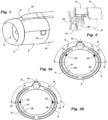
- THE figures 1 and 2 present a propulsion assembly with a nacelle and a dual-flow turbojet supported by a pylon positioned at 12 o'clock (this notion of time being understood in relation to the dial of a clock, corresponding to a cross section of the propulsion assembly) , comprising at the front a circular air inlet cover 2 surrounding an air inlet 4.
- a front part of the nacelle axially forming a cowling section arranged in the extension of the air inlet cover 2, comprises on each side a lower fan cover 6 connected to an upper fan cover 8.
- the nacelle comprises at the rear fan covers 6, 8, movable rear covers 14 which move back under the effect of cylinders arranged longitudinally, to open radial passages formed around the annular vein of cold air. Inversion grilles arranged upstream of the radial passages, under the fan covers 6, 8, slide with the rear movable covers 14 to come into the radial passages of the annular vein in order to direct the flow of cold air towards the Before.
- a lifting point 22 is fixed on a fan casing 41 of the turbojet on each side of the propulsion assembly, on its own supports independent of the supports of the thrust reverser cylinders.
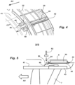
- THE figures 3a, 3b , 4 and 5 present a propulsion assembly according to the invention, the nacelle of which comprises at least one cover 6 disposed in the lower part of this nacelle, and two upper covers 8 covering the sides of the nacelle.
- the thrust reverser grids 30 are connected downstream to the mobile structure of the thrust reverser driven by jacks 40 for opening the thrust reverser.
- cylinders 40 each have a front end 44 fixed to the fan casing 41 and to an outer shell of an intermediate casing 43 (see Figure 5 ) via a support to obtain good rigidity.
- the intermediate casing 43 comprises blades 7 for straightening the flow of the annular vein of fresh air from the turbojet. These blades 7 connect together an inner shell and an outer shell of the intermediate casing.
- a support 46 for a front end 44 of a cylinder 40 is also called front support 46.
- Each cylinder 40 further comprises a rear end 42 fixed to a movable frame driving the inversion grilles 30 and the covers rear mobiles 14.
- two cylinders 40 are arranged a little above a horizontal diameter of the propulsion assembly, at approximately 2 o'clock and 10 o'clock, that is to say in the upper quadrants D and G, as is visible on the figure 3a .
- Each upper cover 8 has a hatch 12 allowing access to the front end of a jack 40 placed behind it to carry out maintenance operations on this jack.
- the front support 46 is fixed on the fan casing 41 and on the intermediate casing shell 43, having a high rigidity allowing it to resist the relaxation and traction forces exerted by the cylinder 40, to oppose in particular the aerodynamic forces applying to the movable rear covers 14, the closing flaps of this vein and the reversing grilles 30 during deployment of the thrust reverser.
- the front support 46 could also be fixed only on the intermediate casing shell 43, in particular when the fan casing 41 is made of composite material: in this case in fact, it would be necessary to provide inserts in the casing 41, which is more complex to manufacture.
- the front support 46 has on each side of the front end of the cylinder 44 a flat surface 50 arranged tangentially relative to the axis of the assembly propellant, comprising two holes 48 aligned in the longitudinal direction, to form a lifting point 22.
- the two flat surfaces 50 of each front support 46 constitute a fixing face of a handling interface 52, the holes 48 allowing tightening on this face, in order to center and stably fix this interface on the propulsion assembly.
- the front supports 46 forming lifting points could also be arranged in other areas of the upper right D and left G quadrants, and in particular at 3 o'clock and 9 o'clock, that is to say along the equator line E, as visible on the figure 3b .
- a lifting hoist 60 comprises two suspensions 62 connected by a horizontal bar 64, each having at the base a hook which attaches to a handling interface 52. Another attachment point on the hoist is at the rear of the turbojet . The propulsion assembly can then be lifted securely to place it on a transport trolley 68.
- the vertical traction on the handling interfaces 52 applies a force on the front supports 46, which is not added simultaneously to the forces exerted thereon by the cylinder 40 during operation of the thrust reverser. In this way we do not combine these two types of effort at the same time on the supports 46, which avoids applying high stresses on them, and dimensioning them for an accumulation of effort.
- the addition of mass on the cylinder fittings in order to form the lifting points 22 with their fixing interfaces 50 can be relatively limited, such that the mass balance for the propulsion assembly is favorable compared to an existing solution in which specific anchoring elements forming lifting points are provided around the perimeter of the annular vein.
- these specific anchoring elements can be removed, the mass thus removed being greater than the mass added to the jack fittings.
- the sizing and fixing of the existing cylinder fittings on the turbojet are generally sufficient to provide a structure capable of support the lifting forces, so that reinforcement of the fittings or their means of attachment to the turbojet will generally not be necessary.
Landscapes
- Engineering & Computer Science (AREA)
- Mechanical Engineering (AREA)
- General Engineering & Computer Science (AREA)
- Aviation & Aerospace Engineering (AREA)
- Chemical & Material Sciences (AREA)
- Combustion & Propulsion (AREA)
- Transportation (AREA)
- Manufacturing & Machinery (AREA)
- Structures Of Non-Positive Displacement Pumps (AREA)
Description
- La présente invention concerne un ensemble propulsif comprenant une nacelle et un turboréacteur comportant un inverseur de poussée à grilles et des points de levage de cet ensemble.
- Les turboréacteurs de motorisation des aéronefs disposés dans une nacelle, reçoivent de l'air frais venant du côté avant, et rejettent du côté arrière les gaz chauds issus de la combustion du carburant délivrant une poussée.
- Pour les turboréacteurs à double flux, des aubes de soufflante disposées autour du moteur génèrent un flux secondaire important d'air froid le long d'une veine annulaire passant entre ce moteur et la nacelle, engendrant une poussée élevée.
- Certaines nacelles comportent un système d'inversion de poussée qui ferme au moins en partie la veine annulaire d'air froid, et rejette le flux secondaire radialement vers l'extérieur en le dirigeant vers l'avant afin de générer une poussée inversée de freinage de l'aéronef. Le document
FR2992292A1 - Un type d'inverseur de poussée à grilles connu, présenté notamment par le document
US-A1-20160160799 , comporte des grilles d'inversion formant une couronne disposée sous des capots de carter de soufflante (ce carter étant souvent appelé « carter fan »), entourant la veine annulaire, qui sont reliées à des capots mobiles arrière coulissant axialement vers l'arrière sous l'effet de vérins présentant une extrémité fixée sur l'extérieur de la veine annulaire du turboréacteur. - Dans une position fermée de l'inverseur pour un flux direct, les capots mobiles arrière ferment des passages latéraux vers l'extérieur formés autour de la veine annulaire.
- Dans une position ouverte de l'inverseur pour un flux inversé, les capots mobiles arrière reculent sur des guidages longitudinaux, en entraînant les grilles qui se positionnent dans les passages d'airs radiaux. Des volets de fermeture ferment au moins partiellement le flux secondaire en arrière de ces passages, en refoulant le flux radialement vers les grilles qui inversent la poussée.
- Par ailleurs les turboréacteurs comportent généralement des points de levage disposés sur le pourtour de la veine annulaire, sous les capots extérieurs, formant des points d'ancrage résistants recevant des interfaces de manutention pour soulever et transporter le turboréacteur et des éléments de la nacelle.
- En particulier on peut former un point de levage de chaque côté latéral du moteur, en limite des grilles d'inverseur.
- Le contour de la veine annulaire du turboréacteur doit alors présenter des ancrages résistants pour réaliser d'une part les supports des extrémités fixes des vérins de commande de l'inverseur de poussée, et d'autre part les points de levage pour la manutention, avec les renforts nécessaires afin d'obtenir une résistance suffisante face aux efforts développés sur ces points, ce qui augmente l'encombrement, la masse et les coûts du turboréacteur et des équipements de la nacelle.
- De plus l'accès aux points de levage nécessite un démontage plus ou moins complet des capots extérieurs de l'inverseur recouvrant ces points, ce qui prend du temps et complexifie les procédés d'intervention.
- La présente invention a notamment pour but d'éviter ces inconvénients de la technique antérieure.
- Elle propose à cet effet un ensemble propulsif comprenant une nacelle et un turboréacteur à double flux, comportant un inverseur de poussée à grilles équipé de grilles mobiles d'inversion de poussée disposées autour d'une veine annulaire d'air frais du turboréacteur, et des vérins disposés autour de la veine annulaire, et présentant chacun une extrémité avant fixée au turboréacteur, chaque vérin présentant en outre une extrémité arrière qui entraîne en translation des capots arrière mobiles et des grilles pour ouvrir dans la veine annulaire des passages radiaux recevant ces grilles, et comportant des points de levage du turboréacteur disposés autour de la veine annulaire d'air frais du turboréacteur, cet ensemble propulsif étant remarquable en ce qu'au moins un des points de levage est formé sur un support de fixation d'une extrémité avant d'un vérin.
- Un avantage de cette nacelle est qu'en utilisant les supports de fixation d'extrémités fixes des vérins de l'inverseur, on met en commun des éléments fortement rigides déjà installés dans la nacelle pour l'inverseur de poussée, disposés autour de la veine annulaire, pour former les points de levage. De cette manière on évite le renforcement d'autres zones autour de la veine annulaire, qu'il faudrait réaliser pour installer des points de levage distincts des ferrures de fixation des vérins. On réduit la masse, l'encombrement et le coût de la nacelle.
- De plus les capots des nacelles comportent généralement des trappes de visite pour accéder aux vérins de l'inverseur de poussée, afin d'effectuer des opérations de maintenance. Une disposition des points de levage à ces endroits permet d'utiliser des trappes de visites existantes pour accéder à ces points, et y fixer des interfaces de manutention.
- L'ensemble propulsif comportant un turboréacteur et une nacelle selon l'invention peut comporter une ou plusieurs des caractéristiques suivantes, qui peuvent être combinées entre elles.
- En particulier, chaque point de levage du turboréacteur peut comporter une ou plusieurs surfaces ou interfaces de fixation destinées au montage d'un outillage de manutention et hissage.
- Dans ce cas, avantageusement chaque point de levage comporte, de chaque côté du vérin, au moins une interface de fixation formée sur ledit support et destinée au montage d'un outillage de manutention et hissage.
- De cette manière on répartit et on équilibre les efforts sur le support, par rapport à l'axe du vérin.
- Avantageusement, au moins une dite interface de fixation présente une surface plate s'étendant tangentiellement par rapport à l'axe de la nacelle et comportant des perçages de fixation d'une interface de manutention.
- Avantageusement, le support de fixation d'une extrémité avant d'un vérin comprend :
- une partie centrale reliée solidairement à une virole d'un carter moteur disposé en aval d'un carter de soufflante du turboréacteur, l'extrémité avant du vérin étant fixée à cette partie centrale, et
- des parties latérales solidaires de la partie centrale et comprenant chacune au moins une interface de fixation.
- Avantageusement, la partie centrale du support est fixée à un cadre formant une bride fixée à la virole dudit carter moteur.
- Avantageusement, ledit carter moteur est constitué par une virole extérieure d'un carter intermédiaire qui comprend des aubes de redressement du flux de la veine annulaire d'air frais du turboréacteur.
- Avantageusement, la partie centrale du support est fixée en outre au carter de soufflante.
- Avantageusement, la nacelle embarque sur chacun de ses deux côtés latéraux un point de levage disposé sur une ferrure de vérin, ladite ferrure de vérin étant montée sur un quadrant supérieur droite ou gauche de la nacelle
- On réalise de manière équilibrée un levage de la nacelle à partir de ces positions.
- Avantageusement, chaque point de fixation est disposé derrière une trappe formée sur un capot de la nacelle.
- Avantageusement, au moins une interface de fixation comprend un assemblage de chape et d'axes.
- L'invention sera mieux comprise et d'autres caractéristiques et avantages apparaîtront plus clairement à la lecture de la description ci-après donnée à titre d'exemple, en référence aux dessins annexés dans lesquels :
- les
figures 1 et 2 présentent une vue d'ensemble et une vue de détail d'un ensemble de nacelle de turboréacteur selon l'art antérieur, comportant des points de levage ; - les
figures 3a et 3b sont des vues de l'avant de l'ensemble propulsif selon l'invention, en coupe transversale passant par les points de levage, selon deux variantes de réalisation possibles ; - la
figure 4 est une vue extérieure d'un vérin d'actionnement de l'inverseur de poussée de la nacelle de cet ensemble propulsif, l'avant de l'ensemble propulsif étant indiqué par flèche AV ; - la
figure 5 est une vue en coupe axiale passant au niveau de ce vérin, l'avant de l'ensemble propulsif étant indiqué par flèche AV ; et - la
figure 6 présente cet ensemble propulsif soulevé par ses points de fixation, disposé au-dessus d'un chariot de transport. - Pour plus de clarté, les éléments identiques ou similaires sont repérés par des signes de référence identiques sur l'ensemble des figures.
- Les
figures 1 et 2 présentent un ensemble propulsif avec une nacelle et un turboréacteur à double flux supportée par un pylône disposé à 12 heures (cette notion d'heure s'entendant par rapport au cadran d'une horloge, correspondant à une section transversale de l'ensemble propulsif), comportant à l'avant un capot circulaire d'entrée d'air 2 entourant une entrée d'air 4. - Une partie avant de la nacelle, formant axialement un tronçon de capotage disposé dans le prolongement du capot d'entrée d'air 2, comporte de chaque côté un capot de soufflante inférieur 6 relié à un capot de soufflante supérieur 8. Un capot de pylône 10 reliant sur le dessus les deux capots supérieurs 8, présente un profilage recouvrant le pylône.
- La nacelle comporte en arrière des capots de soufflante 6, 8, des capots arrière mobiles 14 qui reculent sous l'effet de vérins disposés longitudinalement, pour ouvrir des passages radiaux formés autour de la veine annulaire d'air froid. Des grilles d'inversion disposées en amont des passages radiaux, sous les capots de soufflante 6, 8, coulissent avec les capots mobiles arrière 14 pour venir dans les passages radiaux de la veine annulaire afin de diriger le flux d'air froid vers l'avant.
- Un point de levage 22 est fixé sur un carter de soufflante 41 du turboréacteur de chaque côté de l'ensemble propulsif, sur des supports propres indépendants des supports des vérins de l'inverseur de poussée.
- Les
figures 3a, 3b ,4 et 5 présentent un ensemble propulsif selon l'invention dont la nacelle comporte au moins un capot 6 disposé dans la partie inférieure de cette nacelle, et deux capots supérieurs 8 couvrant les côtés de la nacelle. - Les grilles d'inversion de poussée 30 sont reliées en aval à la structure mobile de l'inverseur de poussée entraînée par des vérins 40 d'ouverture de l'inverseur de poussée.
- Ces vérins 40 comportent chacun une extrémité avant 44 fixée au carter de soufflante 41 et à une virole extérieure d'un carter intermédiaire 43 (voir
figure 5 ) par l'intermédiaire d'un support pour obtenir une bonne rigidité. De façon connue en soi, le carter intermédiaire 43 comprend des aubes 7 de redressement du flux de la veine annulaire d'air frais du turboréacteur. Ces aubes 7 relient entre elles une virole intérieure et une virole extérieure du carter intermédiaire. Dans ce qui suit, un support 46 pour une extrémité avant 44 d'un vérin 40 est aussi appelé support avant 46. Chaque vérin 40 comporte en outre une extrémité arrière 42 fixée à un cadre mobile entraînant les grilles d'inversion 30 et les capots mobiles arrière 14. - En particulier deux vérins 40 sont disposés un peu au-dessus d'un diamètre horizontal de l'ensemble propulsif, à environ 2 heures et 10 heures, c'est-à-dire dans les quadrants supérieurs D et G, comme cela est visible sur la
figure 3a . - Chaque capot supérieur 8 comporte une trappe 12 permettant d'accéder à l'extrémité avant d'un vérin 40 disposée derrière pour effectuer des opérations de maintenance sur ce vérin.
- Le support avant 46 est fixé sur le carter de soufflante 41 et sur la virole de carter intermédiaire 43, en présentant une rigidité élevée lui permettant de résister aux efforts de détente et de traction exercés par le vérin 40, pour s'opposer en particulier aux forces aérodynamiques s'appliquant sur les capots arrière mobiles 14, les volets de fermeture de cette veine et les grilles d'inversion 30 lors d'un déploiement de l'inverseur de poussée.
- En variante, le support avant 46 pourrait aussi être fixé sur la seule virole de carter intermédiaire 43, notamment lorsque que le carter de soufflante 41 est réalisé en matériau composite : dans ce cas en effet, il faudrait prévoir des inserts dans le carter 41, ce qui est plus complexe à fabriquer.
- Le support avant 46 présente de chaque côté de l'extrémité avant du vérin 44 une surface plate 50 disposée tangentiellement par rapport à l'axe de l'ensemble propulsif, comportant deux perçages 48 alignés dans la direction longitudinale, pour former un point de levage 22. Les deux surfaces plates 50 de chaque support avant 46 constituent une face de fixation d'une interface de manutention 52, les perçages 48 permettant un serrage sur cette face, afin de centrer et de fixer de manière stable cette interface sur l'ensemble propulsif.
- En variante, les supports avant 46 formant points de levage pourraient aussi être disposés dans d'autres zones des quadrants supérieurs droit D et gauche G, et en particulier à 3 heures et 9 heures, c'est-à-dire le long de la ligne d'équateur E, comme cela est visible sur la
figure 3b . - La
figure 6 présente après la dépose des trappes 12 et l'ouverture de la partie de la nacelle restant sur l'avion, la fixation d'une interface de manutention 52 sur chaque point de levage 22. On notera que les interfaces de manutention 52 sont rapidement fixées sur la nacelle, sans ouvrir ou déposer des capots extérieurs. - Un palan de levage 60 comporte deux suspensions 62 reliées par une barre horizontale 64, présentant chacune à la base un crochet venant se fixer sur une interface de manutention 52. Un autre point d'accrochage sur le palan se trouve à l'arrière du turboréacteur. On peut ensuite soulever l'ensemble propulsif de manière sécurisée, pour le poser sur un chariot de transport 68.
- La traction verticale sur les interfaces de manutention 52 applique un effort sur les supports avant 46, qui ne s'ajoute pas simultanément aux efforts exercés dessus par le vérin 40 pendant le fonctionnement de l'inverseur de poussée. De cette manière on ne cumule pas en même temps ces deux types d'effort sur les supports 46, ce qui évite d'appliquer dessus des contraintes élevées, et de les dimensionner pour un cumul d'effort.
- On réalise ainsi avec peu de modifications de nacelles existantes, de manière simple et économique, des points de levage 22 qui sont faciles à utiliser.
- L'ajout de masse sur les ferrures de vérins afin de former les points de levage 22 avec leurs interfaces de fixation 50 peut être relativement limité, de telle sorte que le bilan de masse pour l'ensemble propulsif est favorable par rapport à une solution existante dans laquelle des éléments d'ancrage spécifiques formant des points de levage sont prévus sur le pourtour de la veine annulaire.
- En effet, grâce à l'invention, ces éléments d'ancrage spécifiques peuvent être supprimés, la masse ainsi retirée étant supérieure à la masse ajoutée sur les ferrures de vérins.
- Le dimensionnement et la fixation des ferrures de vérins existantes sur le turboréacteur sont généralement suffisants pour procurer une structure apte à supporter les efforts de levage, de telle sorte qu'un renforcement des ferrures ou de leurs moyens de fixation sur le turboréacteur ne sera généralement pas nécessaire.
- En conséquence, l'ajout de masse sur les ferrures résultera essentiellement de la formation des points de levage.
Claims (10)
- Ensemble propulsif comprenant une nacelle et un turboréacteur à double flux, comportant un inverseur de poussée à grilles équipé de grilles mobiles d'inversion de poussée (30) disposées autour d'une veine annulaire d'air frais du turboréacteur, et des vérins (40) disposés autour de la veine annulaire, et présentant chacun une extrémité avant fixée au turboréacteur, chaque vérin présentant en outre une extrémité arrière (42) qui entraîne en translation des capots arrière mobiles (14) et des grilles (30) pour ouvrir dans la veine annulaire des passages radiaux recevant ces grilles (30), et comportant des points de levage du turboréacteur disposés autour de la veine annulaire d'air frais du turboréacteur, cet ensemble propulsif étant caractérisé en ce qu'au moins un des points de levage (22) est formé sur un support (46) de fixation d'une extrémité avant (44) d'un vérin (40).
- Ensemble selon la revendication 1, caractérisé en ce que chaque point de levage (22) comporte, de chaque côté du vérin (40), au moins une interface de fixation (50) formée sur ledit support (46) et destinée au montage d'un outillage de manutention et hissage.
- Ensemble selon la revendication 2, caractérisé en ce qu'au moins une dite interface de fixation (50) présente une surface plate s'étendant tangentiellement par rapport à l'axe de la nacelle et comportant des perçages (48) de fixation d'une interface de manutention (52).
- Ensemble selon l'une des revendications 2 ou 3, caractérisé en ce que le support (46) de fixation d'une extrémité avant (44) d'un vérin comprend :- une partie centrale reliée solidairement à une virole d'un carter moteur (43) disposé en aval d'un carter de soufflante (41) du turboréacteur, l'extrémité avant (44) du vérin étant fixée à cette partie centrale, et- des parties latérales solidaires de la partie centrale et comprenant chacune au moins une interface de fixation (50).
- Ensemble selon la revendication 4, caractérisé en ce que la partie centrale du support (46) est fixée à un cadre (32) formant une bride fixée à la virole dudit carter moteur 43).
- Ensemble selon l'une quelconque des revendications 4 et 5, caractérisé en ce que ledit carter moteur (43) est constitué par une virole extérieure d'un carter intermédiaire qui comprend des aubes (7) de redressement du flux de la veine annulaire d'air frais du turboréacteur.
- Ensemble selon l'une quelconque des revendications 4 à 6, caractérisé en ce que la partie centrale du support (46) est fixée en outre au carter de soufflante (41).
- Ensemble selon l'une quelconque des revendications précédentes, caractérisé en ce que la nacelle embarque sur chacun de ses deux côtés latéraux un point de levage disposé sur une ferrure de vérin, ladite ferrure de vérin étant montée sur un quadrant supérieur droite ou gauche de la nacelle.
- Ensemble selon l'une quelconque des revendications précédentes, caractérisé en ce que chaque point de fixation (22) est disposé derrière une trappe (12) formée sur un capot (8) de la nacelle.
- Ensemble selon la revendication 2, caractérisé en ce qu'au moins une interface de fixation comprend un assemblage de chape et d'axes.
Applications Claiming Priority (2)
| Application Number | Priority Date | Filing Date | Title |
|---|---|---|---|
| FR1851444A FR3078108B1 (fr) | 2018-02-20 | 2018-02-20 | Ensemble propulsif comportant des points de levage disposes sur des supports de verins d’inverseur de poussee |
| PCT/FR2019/050379 WO2019162610A1 (fr) | 2018-02-20 | 2019-02-19 | Ensemble propulsif comportant des points de levage disposés sur des supports de vérins d'inverseur de poussée |
Publications (2)
| Publication Number | Publication Date |
|---|---|
| EP3755887A1 EP3755887A1 (fr) | 2020-12-30 |
| EP3755887B1 true EP3755887B1 (fr) | 2024-08-07 |
Family
ID=61913442
Family Applications (1)
| Application Number | Title | Priority Date | Filing Date |
|---|---|---|---|
| EP19711969.6A Active EP3755887B1 (fr) | 2018-02-20 | 2019-02-19 | Ensemble propulsif comportant des points de levage disposés sur des supports de vérins d'inverseur de poussée |
Country Status (5)
| Country | Link |
|---|---|
| US (1) | US11300076B2 (fr) |
| EP (1) | EP3755887B1 (fr) |
| CN (1) | CN111742117B (fr) |
| FR (1) | FR3078108B1 (fr) |
| WO (1) | WO2019162610A1 (fr) |
Families Citing this family (5)
| Publication number | Priority date | Publication date | Assignee | Title |
|---|---|---|---|---|
| FR3085358B1 (fr) * | 2018-08-31 | 2020-09-25 | Safran Nacelles | Ensemble et procede de manutention d’un ensemble propulsif d’aeronef |
| FR3122905B1 (fr) * | 2021-05-14 | 2026-04-17 | Safran Nacelles | Ensemble propulsif d’aéronef comprenant un actionneur relié à un bras structural tel qu’une aube directrice de sortie |
| CN113775419B (zh) * | 2021-11-11 | 2022-03-08 | 中国航发四川燃气涡轮研究院 | 一种可适应不同方向热变形的挂钩式连接结构 |
| EP4257481A1 (fr) | 2022-04-05 | 2023-10-11 | Rohr, Inc. | Raccord de structure d'entrée de nacelle avec attache de positionnement et support de levage |
| CN115416871B (zh) * | 2022-08-17 | 2024-05-14 | 成都飞机工业(集团)有限责任公司 | 一种发动机推力销快速拆卸方法、装置、设备及介质 |
Family Cites Families (20)
| Publication number | Priority date | Publication date | Assignee | Title |
|---|---|---|---|---|
| US3666211A (en) * | 1970-03-12 | 1972-05-30 | Mc Donnell Douglas Corp | Trijet aircraft |
| US4266741A (en) * | 1978-05-22 | 1981-05-12 | The Boeing Company | Mounting apparatus for fan jet engine having mixed flow nozzle installation |
| US4437627A (en) * | 1982-03-12 | 1984-03-20 | The Boeing Company | Integrated power plant installation system |
| FR2757913B1 (fr) * | 1996-12-26 | 1999-01-29 | Hispano Suiza Sa | Dispositif de pivot entre un element mobile et une structure fixe accessible d'un seul cote |
| US6485247B1 (en) * | 2000-09-28 | 2002-11-26 | The Boeing Company | Engine uplift loader |
| US7419121B2 (en) * | 2004-12-09 | 2008-09-02 | Honeywell International Inc. | Integrated mount duct for use with airborne auxiliary power units and other turbomachines |
| GB0507721D0 (en) * | 2005-04-16 | 2005-05-25 | Rolls Royce Plc | Gas turbine engine mounting arrangement |
| US8101485B2 (en) * | 2005-12-16 | 2012-01-24 | Intel Corporation | Replacement gates to enhance transistor strain |
| FR2934565B1 (fr) * | 2008-08-04 | 2010-09-17 | Airbus France | Systeme d'attache d'un moteur sur une structure d'un aeronef tel qu'une aile volante. |
| FR2946696B1 (fr) * | 2009-06-10 | 2012-04-20 | Aircelle Sa | Dispositif d'inversion de poussee |
| FR2958978B1 (fr) * | 2010-04-20 | 2014-04-18 | Aircelle Sa | Agencement de bielles de volets d'inversion de poussee sur la structure interne fixe d'une nacelle de turboreacteur |
| US8720059B2 (en) * | 2010-04-29 | 2014-05-13 | Spirit Aerosystems, Inc. | Apparatus and method for aircraft engine core exchange |
| FR2965589B1 (fr) * | 2010-10-04 | 2015-05-15 | Aircelle Sa | Inverseur de poussee |
| US8720183B2 (en) * | 2011-03-02 | 2014-05-13 | Spirit Aerosystems, Inc. | Thrust reverser translating sleeve assembly |
| FR2981989B1 (fr) * | 2011-10-31 | 2013-11-01 | Aircelle Sa | Inverseur de poussee a grilles mobiles et capot mobile monobloc |
| FR2989952B1 (fr) * | 2012-04-27 | 2014-04-18 | Aircelle Sa | Nacelle de turboreacteur a section aval |
| FR2992292B1 (fr) * | 2012-06-25 | 2015-02-20 | Aircelle Sa | Dispositif et procede d'assemblage d'une structure fixe d'inverseur de poussee d'un ensemble propulsif d'aeronef |
| US10309343B2 (en) | 2014-11-06 | 2019-06-04 | Rohr, Inc. | Split sleeve hidden door thrust reverser |
| US10077740B2 (en) * | 2015-10-16 | 2018-09-18 | The Boeing Company | Folding door thrust reversers for aircraft engines |
| US20170240388A1 (en) * | 2016-02-23 | 2017-08-24 | Caterpillar Inc. | Hitch assembly for a machine |
-
2018
- 2018-02-20 FR FR1851444A patent/FR3078108B1/fr active Active
-
2019
- 2019-02-19 WO PCT/FR2019/050379 patent/WO2019162610A1/fr not_active Ceased
- 2019-02-19 CN CN201980014110.4A patent/CN111742117B/zh active Active
- 2019-02-19 EP EP19711969.6A patent/EP3755887B1/fr active Active
-
2020
- 2020-08-20 US US16/998,720 patent/US11300076B2/en active Active
Also Published As
| Publication number | Publication date |
|---|---|
| FR3078108B1 (fr) | 2020-01-31 |
| US20200378341A1 (en) | 2020-12-03 |
| FR3078108A1 (fr) | 2019-08-23 |
| EP3755887A1 (fr) | 2020-12-30 |
| CN111742117B (zh) | 2023-05-23 |
| CN111742117A (zh) | 2020-10-02 |
| WO2019162610A1 (fr) | 2019-08-29 |
| US11300076B2 (en) | 2022-04-12 |
Similar Documents
| Publication | Publication Date | Title |
|---|---|---|
| EP3755887B1 (fr) | Ensemble propulsif comportant des points de levage disposés sur des supports de vérins d'inverseur de poussée | |
| CA2602141C (fr) | Systeme propulsif integre comportant un moteur a turboreacteur a double flux | |
| EP1902951B1 (fr) | Système propulsif à pylone intégré pour avion | |
| EP1976758B1 (fr) | Systeme de fixation pour element constitutif d'une nacelle de turboreacteur | |
| FR2965589A1 (fr) | Inverseur de poussee | |
| FR2978990A1 (fr) | Dispositif d'inversion de poussee | |
| EP3164589B1 (fr) | Nacelle de turboreacteur equipee d'un inverseur de poussee, comprenant des decoupes d'evitement du bec mobile d'une aile d'aeronef | |
| EP2885524B1 (fr) | Inverseur de poussée à grilles pour turboréacteur d'aéronef | |
| WO2012045965A1 (fr) | Ensemble propulsif d'aéronef | |
| EP3129632B1 (fr) | Inverseur de poussée de nacelle de turboréacteur comprenant une commande commune pour les capots mobiles et une tuyère variable | |
| EP2247503B1 (fr) | Structure d'accrochage pour turboréacteur | |
| EP4288652B1 (fr) | Inverseur de poussee comprenant des grilles et des capots mobiles assembles par embrevement | |
| EP3768960B1 (fr) | Ensemble propulsif à double flux, comprenant un inverseur de poussée à grilles mobiles | |
| EP3548380A1 (fr) | Nacelle de turboréacteur d'aéronef, ensemble propulsif et aéronef comportant une telle nacelle | |
| EP3728799B1 (fr) | Nacelle de turboréacteur comportant des ouvertures de capots avant d'accès à des points de fixation de la nacelle | |
| EP3755627B1 (fr) | Ensemble de motorisation pour aeronef comportant des points de levage, et chariots pour supporter un tel ensemble | |
| FR3038587A1 (fr) | Nacelle de turboreacteur d’aeronef, ensemble propulsif comportant une nacelle, et aeronef comportant au moins un ensemble propulsif | |
| FR3087497A1 (fr) | Retention axiale haute pour un inverseur a grilles coulissantes a structure en d | |
| CA2882726A1 (fr) | Cadre avant pour une structure d'inverseur de poussee a grilles de deviation | |
| FR3010145A1 (fr) | Inverseur de poussee d’une nacelle de turboreacteur, comprenant des grilles et des verins fixes a l’amont des capots mobiles | |
| EP3507193B1 (fr) | Ensemble propulsif d'aéronef | |
| FR2907853A1 (fr) | Tuyere d'ejection des gaz pour turbomachine a double flux ayant une section d'ejection ou de col variable par deploiement de creneaux |
Legal Events
| Date | Code | Title | Description |
|---|---|---|---|
| STAA | Information on the status of an ep patent application or granted ep patent |
Free format text: STATUS: UNKNOWN |
|
| STAA | Information on the status of an ep patent application or granted ep patent |
Free format text: STATUS: THE INTERNATIONAL PUBLICATION HAS BEEN MADE |
|
| PUAI | Public reference made under article 153(3) epc to a published international application that has entered the european phase |
Free format text: ORIGINAL CODE: 0009012 |
|
| STAA | Information on the status of an ep patent application or granted ep patent |
Free format text: STATUS: REQUEST FOR EXAMINATION WAS MADE |
|
| 17P | Request for examination filed |
Effective date: 20200828 |
|
| AK | Designated contracting states |
Kind code of ref document: A1 Designated state(s): AL AT BE BG CH CY CZ DE DK EE ES FI FR GB GR HR HU IE IS IT LI LT LU LV MC MK MT NL NO PL PT RO RS SE SI SK SM TR |
|
| AX | Request for extension of the european patent |
Extension state: BA ME |
|
| DAV | Request for validation of the european patent (deleted) | ||
| DAX | Request for extension of the european patent (deleted) | ||
| STAA | Information on the status of an ep patent application or granted ep patent |
Free format text: STATUS: EXAMINATION IS IN PROGRESS |
|
| 17Q | First examination report despatched |
Effective date: 20220906 |
|
| GRAP | Despatch of communication of intention to grant a patent |
Free format text: ORIGINAL CODE: EPIDOSNIGR1 |
|
| STAA | Information on the status of an ep patent application or granted ep patent |
Free format text: STATUS: GRANT OF PATENT IS INTENDED |
|
| INTG | Intention to grant announced |
Effective date: 20240315 |
|
| GRAS | Grant fee paid |
Free format text: ORIGINAL CODE: EPIDOSNIGR3 |
|
| GRAA | (expected) grant |
Free format text: ORIGINAL CODE: 0009210 |
|
| STAA | Information on the status of an ep patent application or granted ep patent |
Free format text: STATUS: THE PATENT HAS BEEN GRANTED |
|
| AK | Designated contracting states |
Kind code of ref document: B1 Designated state(s): AL AT BE BG CH CY CZ DE DK EE ES FI FR GB GR HR HU IE IS IT LI LT LU LV MC MK MT NL NO PL PT RO RS SE SI SK SM TR |
|
| REG | Reference to a national code |
Ref country code: GB Ref legal event code: FG4D Free format text: NOT ENGLISH |
|
| REG | Reference to a national code |
Ref country code: CH Ref legal event code: EP |
|
| REG | Reference to a national code |
Ref country code: IE Ref legal event code: FG4D Free format text: LANGUAGE OF EP DOCUMENT: FRENCH |
|
| REG | Reference to a national code |
Ref country code: DE Ref legal event code: R096 Ref document number: 602019056519 Country of ref document: DE |
|
| REG | Reference to a national code |
Ref country code: LT Ref legal event code: MG9D |
|
| REG | Reference to a national code |
Ref country code: NL Ref legal event code: MP Effective date: 20240807 |
|
| PG25 | Lapsed in a contracting state [announced via postgrant information from national office to epo] |
Ref country code: NO Free format text: LAPSE BECAUSE OF FAILURE TO SUBMIT A TRANSLATION OF THE DESCRIPTION OR TO PAY THE FEE WITHIN THE PRESCRIBED TIME-LIMIT Effective date: 20241107 |
|
| REG | Reference to a national code |
Ref country code: AT Ref legal event code: MK05 Ref document number: 1711156 Country of ref document: AT Kind code of ref document: T Effective date: 20240807 |
|
| PG25 | Lapsed in a contracting state [announced via postgrant information from national office to epo] |
Ref country code: NL Free format text: LAPSE BECAUSE OF FAILURE TO SUBMIT A TRANSLATION OF THE DESCRIPTION OR TO PAY THE FEE WITHIN THE PRESCRIBED TIME-LIMIT Effective date: 20240807 Ref country code: PT Free format text: LAPSE BECAUSE OF FAILURE TO SUBMIT A TRANSLATION OF THE DESCRIPTION OR TO PAY THE FEE WITHIN THE PRESCRIBED TIME-LIMIT Effective date: 20241209 Ref country code: GR Free format text: LAPSE BECAUSE OF FAILURE TO SUBMIT A TRANSLATION OF THE DESCRIPTION OR TO PAY THE FEE WITHIN THE PRESCRIBED TIME-LIMIT Effective date: 20241108 Ref country code: FI Free format text: LAPSE BECAUSE OF FAILURE TO SUBMIT A TRANSLATION OF THE DESCRIPTION OR TO PAY THE FEE WITHIN THE PRESCRIBED TIME-LIMIT Effective date: 20240807 Ref country code: PL Free format text: LAPSE BECAUSE OF FAILURE TO SUBMIT A TRANSLATION OF THE DESCRIPTION OR TO PAY THE FEE WITHIN THE PRESCRIBED TIME-LIMIT Effective date: 20240807 |
|
| PG25 | Lapsed in a contracting state [announced via postgrant information from national office to epo] |
Ref country code: BG Free format text: LAPSE BECAUSE OF FAILURE TO SUBMIT A TRANSLATION OF THE DESCRIPTION OR TO PAY THE FEE WITHIN THE PRESCRIBED TIME-LIMIT Effective date: 20240807 |
|
| PG25 | Lapsed in a contracting state [announced via postgrant information from national office to epo] |
Ref country code: LV Free format text: LAPSE BECAUSE OF FAILURE TO SUBMIT A TRANSLATION OF THE DESCRIPTION OR TO PAY THE FEE WITHIN THE PRESCRIBED TIME-LIMIT Effective date: 20240807 |
|
| PG25 | Lapsed in a contracting state [announced via postgrant information from national office to epo] |
Ref country code: AT Free format text: LAPSE BECAUSE OF FAILURE TO SUBMIT A TRANSLATION OF THE DESCRIPTION OR TO PAY THE FEE WITHIN THE PRESCRIBED TIME-LIMIT Effective date: 20240807 Ref country code: IS Free format text: LAPSE BECAUSE OF FAILURE TO SUBMIT A TRANSLATION OF THE DESCRIPTION OR TO PAY THE FEE WITHIN THE PRESCRIBED TIME-LIMIT Effective date: 20241207 |
|
| PG25 | Lapsed in a contracting state [announced via postgrant information from national office to epo] |
Ref country code: HR Free format text: LAPSE BECAUSE OF FAILURE TO SUBMIT A TRANSLATION OF THE DESCRIPTION OR TO PAY THE FEE WITHIN THE PRESCRIBED TIME-LIMIT Effective date: 20240807 |
|
| PG25 | Lapsed in a contracting state [announced via postgrant information from national office to epo] |
Ref country code: ES Free format text: LAPSE BECAUSE OF FAILURE TO SUBMIT A TRANSLATION OF THE DESCRIPTION OR TO PAY THE FEE WITHIN THE PRESCRIBED TIME-LIMIT Effective date: 20240807 Ref country code: RS Free format text: LAPSE BECAUSE OF FAILURE TO SUBMIT A TRANSLATION OF THE DESCRIPTION OR TO PAY THE FEE WITHIN THE PRESCRIBED TIME-LIMIT Effective date: 20241107 |
|
| PG25 | Lapsed in a contracting state [announced via postgrant information from national office to epo] |
Ref country code: RS Free format text: LAPSE BECAUSE OF FAILURE TO SUBMIT A TRANSLATION OF THE DESCRIPTION OR TO PAY THE FEE WITHIN THE PRESCRIBED TIME-LIMIT Effective date: 20241107 Ref country code: PT Free format text: LAPSE BECAUSE OF FAILURE TO SUBMIT A TRANSLATION OF THE DESCRIPTION OR TO PAY THE FEE WITHIN THE PRESCRIBED TIME-LIMIT Effective date: 20241209 Ref country code: PL Free format text: LAPSE BECAUSE OF FAILURE TO SUBMIT A TRANSLATION OF THE DESCRIPTION OR TO PAY THE FEE WITHIN THE PRESCRIBED TIME-LIMIT Effective date: 20240807 Ref country code: NO Free format text: LAPSE BECAUSE OF FAILURE TO SUBMIT A TRANSLATION OF THE DESCRIPTION OR TO PAY THE FEE WITHIN THE PRESCRIBED TIME-LIMIT Effective date: 20241107 Ref country code: NL Free format text: LAPSE BECAUSE OF FAILURE TO SUBMIT A TRANSLATION OF THE DESCRIPTION OR TO PAY THE FEE WITHIN THE PRESCRIBED TIME-LIMIT Effective date: 20240807 Ref country code: LV Free format text: LAPSE BECAUSE OF FAILURE TO SUBMIT A TRANSLATION OF THE DESCRIPTION OR TO PAY THE FEE WITHIN THE PRESCRIBED TIME-LIMIT Effective date: 20240807 Ref country code: IS Free format text: LAPSE BECAUSE OF FAILURE TO SUBMIT A TRANSLATION OF THE DESCRIPTION OR TO PAY THE FEE WITHIN THE PRESCRIBED TIME-LIMIT Effective date: 20241207 Ref country code: HR Free format text: LAPSE BECAUSE OF FAILURE TO SUBMIT A TRANSLATION OF THE DESCRIPTION OR TO PAY THE FEE WITHIN THE PRESCRIBED TIME-LIMIT Effective date: 20240807 Ref country code: GR Free format text: LAPSE BECAUSE OF FAILURE TO SUBMIT A TRANSLATION OF THE DESCRIPTION OR TO PAY THE FEE WITHIN THE PRESCRIBED TIME-LIMIT Effective date: 20241108 Ref country code: FI Free format text: LAPSE BECAUSE OF FAILURE TO SUBMIT A TRANSLATION OF THE DESCRIPTION OR TO PAY THE FEE WITHIN THE PRESCRIBED TIME-LIMIT Effective date: 20240807 Ref country code: ES Free format text: LAPSE BECAUSE OF FAILURE TO SUBMIT A TRANSLATION OF THE DESCRIPTION OR TO PAY THE FEE WITHIN THE PRESCRIBED TIME-LIMIT Effective date: 20240807 Ref country code: BG Free format text: LAPSE BECAUSE OF FAILURE TO SUBMIT A TRANSLATION OF THE DESCRIPTION OR TO PAY THE FEE WITHIN THE PRESCRIBED TIME-LIMIT Effective date: 20240807 Ref country code: AT Free format text: LAPSE BECAUSE OF FAILURE TO SUBMIT A TRANSLATION OF THE DESCRIPTION OR TO PAY THE FEE WITHIN THE PRESCRIBED TIME-LIMIT Effective date: 20240807 |
|
| PG25 | Lapsed in a contracting state [announced via postgrant information from national office to epo] |
Ref country code: SM Free format text: LAPSE BECAUSE OF FAILURE TO SUBMIT A TRANSLATION OF THE DESCRIPTION OR TO PAY THE FEE WITHIN THE PRESCRIBED TIME-LIMIT Effective date: 20240807 Ref country code: RO Free format text: LAPSE BECAUSE OF FAILURE TO SUBMIT A TRANSLATION OF THE DESCRIPTION OR TO PAY THE FEE WITHIN THE PRESCRIBED TIME-LIMIT Effective date: 20240807 Ref country code: DK Free format text: LAPSE BECAUSE OF FAILURE TO SUBMIT A TRANSLATION OF THE DESCRIPTION OR TO PAY THE FEE WITHIN THE PRESCRIBED TIME-LIMIT Effective date: 20240807 |
|
| PG25 | Lapsed in a contracting state [announced via postgrant information from national office to epo] |
Ref country code: EE Free format text: LAPSE BECAUSE OF FAILURE TO SUBMIT A TRANSLATION OF THE DESCRIPTION OR TO PAY THE FEE WITHIN THE PRESCRIBED TIME-LIMIT Effective date: 20240807 |
|
| PG25 | Lapsed in a contracting state [announced via postgrant information from national office to epo] |
Ref country code: CZ Free format text: LAPSE BECAUSE OF FAILURE TO SUBMIT A TRANSLATION OF THE DESCRIPTION OR TO PAY THE FEE WITHIN THE PRESCRIBED TIME-LIMIT Effective date: 20240807 |
|
| PG25 | Lapsed in a contracting state [announced via postgrant information from national office to epo] |
Ref country code: SK Free format text: LAPSE BECAUSE OF FAILURE TO SUBMIT A TRANSLATION OF THE DESCRIPTION OR TO PAY THE FEE WITHIN THE PRESCRIBED TIME-LIMIT Effective date: 20240807 |
|
| REG | Reference to a national code |
Ref country code: DE Ref legal event code: R097 Ref document number: 602019056519 Country of ref document: DE |
|
| PLBE | No opposition filed within time limit |
Free format text: ORIGINAL CODE: 0009261 |
|
| STAA | Information on the status of an ep patent application or granted ep patent |
Free format text: STATUS: NO OPPOSITION FILED WITHIN TIME LIMIT |
|
| 26N | No opposition filed |
Effective date: 20250508 |
|
| PG25 | Lapsed in a contracting state [announced via postgrant information from national office to epo] |
Ref country code: SE Free format text: LAPSE BECAUSE OF FAILURE TO SUBMIT A TRANSLATION OF THE DESCRIPTION OR TO PAY THE FEE WITHIN THE PRESCRIBED TIME-LIMIT Effective date: 20240807 |
|
| PG25 | Lapsed in a contracting state [announced via postgrant information from national office to epo] |
Ref country code: MC Free format text: LAPSE BECAUSE OF FAILURE TO SUBMIT A TRANSLATION OF THE DESCRIPTION OR TO PAY THE FEE WITHIN THE PRESCRIBED TIME-LIMIT Effective date: 20240807 |
|
| REG | Reference to a national code |
Ref country code: CH Ref legal event code: PL |
|
| PG25 | Lapsed in a contracting state [announced via postgrant information from national office to epo] |
Ref country code: LU Free format text: LAPSE BECAUSE OF NON-PAYMENT OF DUE FEES Effective date: 20250219 |
|
| PG25 | Lapsed in a contracting state [announced via postgrant information from national office to epo] |
Ref country code: CH Free format text: LAPSE BECAUSE OF NON-PAYMENT OF DUE FEES Effective date: 20250228 |
|
| REG | Reference to a national code |
Ref country code: BE Ref legal event code: MM Effective date: 20250228 |
|
| PG25 | Lapsed in a contracting state [announced via postgrant information from national office to epo] |
Ref country code: BE Free format text: LAPSE BECAUSE OF NON-PAYMENT OF DUE FEES Effective date: 20250228 |
|
| PG25 | Lapsed in a contracting state [announced via postgrant information from national office to epo] |
Ref country code: IE Free format text: LAPSE BECAUSE OF NON-PAYMENT OF DUE FEES Effective date: 20250219 |
|
| PG25 | Lapsed in a contracting state [announced via postgrant information from national office to epo] |
Ref country code: IT Free format text: LAPSE BECAUSE OF FAILURE TO SUBMIT A TRANSLATION OF THE DESCRIPTION OR TO PAY THE FEE WITHIN THE PRESCRIBED TIME-LIMIT Effective date: 20240807 |
|
| PGFP | Annual fee paid to national office [announced via postgrant information from national office to epo] |
Ref country code: GB Payment date: 20260219 Year of fee payment: 8 |
|
| PGFP | Annual fee paid to national office [announced via postgrant information from national office to epo] |
Ref country code: DE Payment date: 20260217 Year of fee payment: 8 |
|
| PGFP | Annual fee paid to national office [announced via postgrant information from national office to epo] |
Ref country code: FR Payment date: 20260213 Year of fee payment: 8 |