EP3755850B1 - Stormwater filter socks with multiple separated tubes - Google Patents
Stormwater filter socks with multiple separated tubes Download PDFInfo
- Publication number
- EP3755850B1 EP3755850B1 EP19712862.2A EP19712862A EP3755850B1 EP 3755850 B1 EP3755850 B1 EP 3755850B1 EP 19712862 A EP19712862 A EP 19712862A EP 3755850 B1 EP3755850 B1 EP 3755850B1
- Authority
- EP
- European Patent Office
- Prior art keywords
- tube
- downstream
- upstream
- filter sock
- stormwater filter
- Prior art date
- Legal status (The legal status is an assumption and is not a legal conclusion. Google has not performed a legal analysis and makes no representation as to the accuracy of the status listed.)
- Active
Links
Images


Classifications
-
- C—CHEMISTRY; METALLURGY
- C02—TREATMENT OF WATER, WASTE WATER, SEWAGE, OR SLUDGE
- C02F—TREATMENT OF WATER, WASTE WATER, SEWAGE, OR SLUDGE
- C02F1/00—Treatment of water, waste water, or sewage
- C02F1/28—Treatment of water, waste water, or sewage by sorption
- C02F1/281—Treatment of water, waste water, or sewage by sorption using inorganic sorbents
-
- B—PERFORMING OPERATIONS; TRANSPORTING
- B01—PHYSICAL OR CHEMICAL PROCESSES OR APPARATUS IN GENERAL
- B01D—SEPARATION
- B01D15/00—Separating processes involving the treatment of liquids with solid sorbents; Apparatus therefor
- B01D15/08—Selective adsorption, e.g. chromatography
- B01D15/10—Selective adsorption, e.g. chromatography characterised by constructional or operational features
- B01D15/18—Selective adsorption, e.g. chromatography characterised by constructional or operational features relating to flow patterns
-
- B—PERFORMING OPERATIONS; TRANSPORTING
- B01—PHYSICAL OR CHEMICAL PROCESSES OR APPARATUS IN GENERAL
- B01J—CHEMICAL OR PHYSICAL PROCESSES, e.g. CATALYSIS OR COLLOID CHEMISTRY; THEIR RELEVANT APPARATUS
- B01J20/00—Solid sorbent compositions or filter aid compositions; Sorbents for chromatography; Processes for preparing, regenerating or reactivating thereof
- B01J20/28—Solid sorbent compositions or filter aid compositions; Sorbents for chromatography; Processes for preparing, regenerating or reactivating thereof characterised by their form or physical properties
- B01J20/28014—Solid sorbent compositions or filter aid compositions; Sorbents for chromatography; Processes for preparing, regenerating or reactivating thereof characterised by their form or physical properties characterised by their form
- B01J20/2805—Sorbents inside a permeable or porous casing, e.g. inside a container, bag or membrane
-
- C—CHEMISTRY; METALLURGY
- C02—TREATMENT OF WATER, WASTE WATER, SEWAGE, OR SLUDGE
- C02F—TREATMENT OF WATER, WASTE WATER, SEWAGE, OR SLUDGE
- C02F1/00—Treatment of water, waste water, or sewage
- C02F1/28—Treatment of water, waste water, or sewage by sorption
- C02F1/283—Treatment of water, waste water, or sewage by sorption using coal, charred products, or inorganic mixtures containing them
-
- C—CHEMISTRY; METALLURGY
- C02—TREATMENT OF WATER, WASTE WATER, SEWAGE, OR SLUDGE
- C02F—TREATMENT OF WATER, WASTE WATER, SEWAGE, OR SLUDGE
- C02F1/00—Treatment of water, waste water, or sewage
- C02F1/28—Treatment of water, waste water, or sewage by sorption
- C02F1/285—Treatment of water, waste water, or sewage by sorption using synthetic organic sorbents
-
- C—CHEMISTRY; METALLURGY
- C02—TREATMENT OF WATER, WASTE WATER, SEWAGE, OR SLUDGE
- C02F—TREATMENT OF WATER, WASTE WATER, SEWAGE, OR SLUDGE
- C02F1/00—Treatment of water, waste water, or sewage
- C02F1/28—Treatment of water, waste water, or sewage by sorption
- C02F1/286—Treatment of water, waste water, or sewage by sorption using natural organic sorbents or derivatives thereof
-
- E—FIXED CONSTRUCTIONS
- E03—WATER SUPPLY; SEWERAGE
- E03F—SEWERS; CESSPOOLS
- E03F5/00—Sewerage structures
- E03F5/04—Gullies inlets, road sinks, floor drains with or without odour seals or sediment traps
- E03F5/0401—Gullies for use in roads or pavements
- E03F5/0404—Gullies for use in roads or pavements with a permanent or temporary filtering device; Filtering devices specially adapted therefor
-
- C—CHEMISTRY; METALLURGY
- C02—TREATMENT OF WATER, WASTE WATER, SEWAGE, OR SLUDGE
- C02F—TREATMENT OF WATER, WASTE WATER, SEWAGE, OR SLUDGE
- C02F2101/00—Nature of the contaminant
- C02F2101/10—Inorganic compounds
- C02F2101/20—Heavy metals or heavy metal compounds
-
- C—CHEMISTRY; METALLURGY
- C02—TREATMENT OF WATER, WASTE WATER, SEWAGE, OR SLUDGE
- C02F—TREATMENT OF WATER, WASTE WATER, SEWAGE, OR SLUDGE
- C02F2101/00—Nature of the contaminant
- C02F2101/30—Organic compounds
- C02F2101/32—Hydrocarbons, e.g. oil
-
- C—CHEMISTRY; METALLURGY
- C02—TREATMENT OF WATER, WASTE WATER, SEWAGE, OR SLUDGE
- C02F—TREATMENT OF WATER, WASTE WATER, SEWAGE, OR SLUDGE
- C02F2103/00—Nature of the water, waste water, sewage or sludge to be treated
- C02F2103/001—Runoff or storm water
-
- C—CHEMISTRY; METALLURGY
- C02—TREATMENT OF WATER, WASTE WATER, SEWAGE, OR SLUDGE
- C02F—TREATMENT OF WATER, WASTE WATER, SEWAGE, OR SLUDGE
- C02F2201/00—Apparatus for treatment of water, waste water or sewage
- C02F2201/002—Construction details of the apparatus
Definitions
- the present invention relates to stormwater filter socks, and more particularly relates to stormwater filter socks with multiple separated tubes.
- Current stormwater filter socks may include a large tube that can be sewn or bonded to form two or more adjacent touching tubes that may be filled with absorbent media.
- filter socks with tubes that contact each other have poor lateral flexibility.
- US 2016/030867 discloses a filtration device according to the preamble of claim 1.
- US 7455766 discloses a system for filtering stormwater-carried debris flowing through a gutter inlet into a catch basin.
- the present invention provides multiple-tube stormwater filter socks according to claim 1, that may be used to mitigate stormwater environmental runoff of sediment, hydrocarbons, nutrients and heavy metals.
- the present invention provides a stormwater filter sock according to claim 1. Non-essential features of the stormwater filter sock are set out in the dependent claims.
- the stormwater filter socks may be placed around top grates of storm drain chambers, and around other environmental runoff sources such as trash bins, roof downspouts, outdoor material stockpiles and the like.
- the multiple-tube stormwater filter socks may be used to mitigate drips and spills of hydrocarbons such as motor oils, may be used to contain nutrients, and may be used to contain zinc, copper, lead, chromium, cadmium and other heavy metals.
- the present invention provides multiple-tube stormwater filter socks comprising two or more side-by-side joined tubes spaced apart from each other by a separator web, and are filled with absorbent media.
- the tubes of the present invention are attached to each other, but spaced apart, to significantly improve side-to-side flexibility.
- the multiple-tube stormwater filter socks of the present invention can be easily laterally bent for non-linear positioning during use.
- the multiple-tube stormwater filter socks of the present invention can be used to remove pollutants from contaminated stormwater runoff. Polluted water flows through the socks where the pollution is either stopped or absorbed. Pollutants include but are not limited to heavy metals such as cadmium, chromium, zinc, lead and copper, oil and other hydrocarbon-based liquids, nutrients, sediment, debris and trash.
- Figs. 1 and 2 illustrate a multiple-tube stormwater filter sock 5 in accordance with an embodiment of the present invention.
- a multiple-tube stormwater filter sock 5 is in an extended position, and in Fig. 2 it is in a generally L-shaped position installed around a portion of a perimeter of a storm drain grate G.
- the multiple-tube stormwater filter sock 5 includes a downstream tube 10, an upstream tube 20, and a separator web 30 having a width W.
- Multiple hand straps 40 are connected to the upstream tube 20 at strap attachment locations 42. As shown in Fig.
- a constricted corner C is formed where the downstream and upstream tubes 10' and 20' are drawn together.
- the separator web 30 between the downstream and upstream tubes 10 and 20 allows the multiple-tube stormwater filter sock 5 to be easily installed in various bent or nonlinear configurations. Any suitable angle may be formed at the bent corner C portion, for example, 10°, 30°, 45°, 60°, 90°, or any other desired angle.
- a single bent stormwater filter sock 5 is shown in Fig. 2 , it is to be understood that two or more of the filter socks 5 may be required to fully enclose a storm drain or other structure, e.g., by laying ends of multiple filter socks next to each other or on top of each other in overlapping configurations.
- Fig. 3 is a partially schematic cross-sectional view showing the downstream tube 10 and the upstream tube 20 spaced apart by the separator web 30.
- the downstream tube 10 includes a liquid permeable outer shell 12 surrounding a downstream absorbent media 14.
- the upstream tube 20 includes a liquid permeable outer shell 22 surrounding an upstream absorbent media 24.
- the separator web 30 is formed from a downstream web extension flap 16 extending from the downstream tube 10 and an upstream web extension flap 26 extending from the upstream tube 20.
- the downstream and upstream web extension flaps 16 and 26 are fastened together by at least one sewn seam 32 to form the separator web 30.
- the downstream absorbent media 14 contained within the liquid permeable outer shell 12 may compromise a granular heavy metal ion-absorptive material, as more fully described below.
- the upstream absorbent media 24 contained within the liquid permeable outer shell 22 is in the form of a rolled-up mat made of fiberous hydrocarbon-absorbent material.
- any other suitable form of absorbent material may be used, such as bulk or loose fibers of hydrocarbon-absorbing material, woven or non-woven fabrics of hydrocarbon-absorbing material, and the like.
- a mat of absorbent material is used as the upstream absorbent media 24 as shown in Fig.
- the upstream absorbent media 24 may be made of hydrocarbon-absorbing materials such as polypropylene, polyester, cellulosic material, or the like.
- the cross-section of the downstream tube 10 may be generally circular and may have a diameter Di, and the cross-section of the upstream tube 20 may also be generally circular and may have a diameter D 2 .
- the downstream and upstream tubes 10 and 20 may not necessarily have circular cross-sections, in which case their cross-sectional dimensions in the horizontal direction may be descried as their widths.
- Fig. 4 schematically illustrates a cross-section of a downstream liquid permeable outer shell 12 that may be filled with a downstream absorbent media 14 in accordance with another embodiment of the present invention.
- the liquid permeable outer shell 12 forms opposing downstream web extension flaps 16 and 17 running along the length of the outer shell 12 that may be sewn together by a sewn seam 34.
- the downstream liquid permeable outer shell 12 may be attached to an upstream liquid permeable shell 22 similar to that shown in Fig. 3 , or may be attached to an upstream liquid permeable shell that is a mirror image of the downstream liquid permeable shell shown in Fig. 4 .
- Fig. 5 schematically illustrates a cross-section of a downstream liquid permeable outer shell 12 that may be filled with a downstream absorbent media 14 in accordance with another embodiment of the present invention.
- the liquid permeable outer shell 12 has an exterior downstream web extension flap 16 and an interior edge 18 that may be sewn together by a sewn seam 36.
- the downstream liquid permeable outer shell 12 may be attached to an upstream liquid permeable shell 22 similar to that shown in Fig. 3 , or may be attached to an upstream liquid permeable shell that is a mirror image of the downstream liquid permeable shell 12 shown in Fig. 5 .
- Figs. 6 and 7 are is a partially schematic sectional views illustrating the fabrication of a multiple-tube stormwater filter sock 105 in accordance with another embodiment of the present invention.
- flat sheet stock may be formed into a starting tube 110 by sewing, gluing, welding, or the like.
- the starting tube 110 may be made of liquid permeable material as described above, and includes one side 112 to be formed into a downstream tube, and another side 113 to be formed into an upstream tube.
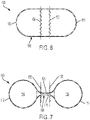
- the starting tube 110 shown in Fig. 6 may be divided into separate upstream and downstream tubes 112 and 113 by sewn seams 132 and 133. When the seams 132 and 133 are sewn as shown in Fig.
- a separator web 130 similar to the separator web 30 described above is provided.
- the separator web 130 includes a lower web panel 116 and an upper web panel 126 formed from portions of the starting tube 110.
- the downstream tube 112 may be filled with a downstream absorbent material 114 similar to the downstream absorbent media 14 described in the embodiment above.
- the upstream tube 113 may be filled with an upstream absorbent media 124 similar to the upstream absorbent media 24 described in the embodiment above.
- the downstream tube 10, 112 may have a horizontal width
- the upstream tube 20, 113 may have a horizontal width
- the width W of the separator web 30, 130 may be at least 10 percent of the horizontal width of either the downstream or upstream tubes.
- the width W of the separator web 30, 130 may be at least 20 percent of the horizontal widths of the downstream and upstream tubes.
- the width W of the separator web 30, 130 may be at least 20 percent of either the dimeter D 1 of the downstream tube 10, 112 or the diameter D 2 of the upstream tube 20, 113.
- the width W of the separator web 30, 130 may be at least 25 percent of the diameter D 1 of the downstream tube and the diameter D 2 of the upstream tube.
- the horizontal widths of the downstream 10, 112 and upstream 20, 113 tubes are from (2.54 to 25.4 cm (1 to 10 inches), or from 5.08 to 15.24 cm (2 to 6 inches).
- the ratio of the horizontal width of the upstream tube 20, 113 to the horizontal width of the downstream tube 10, 112 may range from 1:2 to 16:1.
- the horizontal widths of the downstream and upstream tubes may be substantially the same.
- the upstream tube 20, 113 has a cross-sectional area
- the downstream tube 10, 112 has a cross-sectional area
- the ratio of the upstream to downstream tube cross-sectional areas may range from 1:2 to 16:1.
- the ratio of the upstream tube 20, 113 cross-sectional area to the downstream tube 10, 112 cross-sectional area is from 1:2 to 2:1, for example, the cross-sectional areas of the upstream and downstream tubes may be the same, i.e., a 1:1 ratio.
- the cross-sectional area of the upstream tube 20, 113 may be typically equal to the downstream tube 10, 112, for example, 62 cm 2 (9.6 square inches). If the cross-sectional shape of each tube is circular, this corresponds to a 8.89 cm (3.5-inch) diameter tube.
- the upstream tube 20, 113 may contain a media that absorbs hydrocarbons, such as lubricating oils, and filters out sediments and particles.
- the upstream absorbent media 24 may comprise polymeric fibers, natural fibers, loose oil-absorbing particles, and the like.
- a typical media is a blend of polypropylene and polyester fibers.
- the media contained in the upstream tube 20, 113 does not significantly swell or expand during use, e.g., the media does not swell to many-times its volume when contacted with water or other liquids.
- the width W of the separator web 30, as well as that of the separator web 130, may typically be from 1.27 to 7.62 cm (0.5 to 3 inches), for example, from 2.54 to 5.08 cm (1 to 2 inches).
- the multiple-tube stormwater filter sock 5, 105 has a side-by-side, two-tube arrangement with a 2.54 cm (1-inch) separator web width W between the downstream tube 10, 112 and the upstream tube 20, 113.
- the separator webs 30 and 130 may have a highly visible strip, e.g., having a bright color, applied thereto to increase visibility.
- the downstream tubes 12 and 112, and the upstream tubes 22 and 113 may be filled with the same or different media types.
- the media contained in the downstream tube 10, 112 and/or the media contained in the upstream tube 20, 113 does not significantly swell or expand during use, e.g., the media does not swell to many-times its volume when contacted with water or other liquids.
- the downstream tube 10, 112 may be filled with a heavy metal ion absorptive media, such as zeolite, perlite, activated carbon, cellulosic materials (e.g., peat, wood chips, ground or shredded paper products) and/or graphene, or a blend of these. Placing the heavy metal absorptive media downstream reduces the probability that it will get fouled from hydrocarbon binding.
- a heavy metal ion absorptive media such as zeolite, perlite, activated carbon, cellulosic materials (e.g., peat, wood chips, ground or shredded paper products) and/or graphene, or a blend of these.
- a heavy metal absorptive media such as zeolite, perlite, activated carbon, cellulosic materials (e.g., peat, wood chips, ground or shredded paper products) and/or graphene, or a blend of these. Placing the heavy metal absorptive media downstream reduces the
- the liquid permeable outer shells 12, 22, 112 and 113 may be made of any material that allows free passage of liquid hydrocarbons and stormwater, such as woven or non-woven fabrics comprising polypropylene, polyester, polyethylene, polyamide, nylon and the like. Any suitable weight of material may be used for the liquid permeable outer shells 12, 22, 112 and 113, for example, from 67 to 678 g/m 2 (2 to 20 ounce/sq. yard), or from 101 to 339 g/m 2 (3 to 10 ounce/sq. yard).
- the liquid permeable outer shells 12, 22, 112 and 113 may have typical water flow rates measured by the ASTM D4491 standard test of from 122 to 732 m 3 /m 2 ⁇ h (50 to 300 gallons/minute/sq. foot), for example, from 366 to 488 m 3 /m 2 ⁇ h (150 to 200 gallons/minute/sq. foot).
- the outer layer may comprise a 180 g/m 3 (5.3-ounce/sq. yard), woven monofilament polypropylene fabric with a water flow rate of 415 m 3 /m 2 ⁇ h (170 gallons/minute/sq. foot) as tested by ASTM D4491.
- Table 1 Amount of Heavy Metal Filtration Media (Upstream) (Downstream) Example Cross-Sectional Area Ratio ⁇ Upstream Dia cm (in) Downstream Dia cm (in) Wt (#) of Hydrocarbon - Sediment Media per 30.5 cm (linear foot) Wt (#) of Heavy Metal Media ⁇ per 30.5 cm (linear foot) 1 1:1 8.9 (3.50) 8.9 (3.50) 0.15 2.7 2 1.56:1 12.7 (5.00) 10.2 (4.00) 0.21 3.1 3 2.42:1 17.8 (7.00) 11.4 (4.50) 0.30 3.5 ⁇ Ratio of upstream tube to downstream tube ⁇ 50% by volume activated carbon, Calgon Carbon Corp from - Type DSR-C; and 50% by volume clinoptilite zeolite (calcium ion type
Landscapes
- Chemical & Material Sciences (AREA)
- Hydrology & Water Resources (AREA)
- Engineering & Computer Science (AREA)
- Life Sciences & Earth Sciences (AREA)
- Water Supply & Treatment (AREA)
- Organic Chemistry (AREA)
- Environmental & Geological Engineering (AREA)
- Analytical Chemistry (AREA)
- Chemical Kinetics & Catalysis (AREA)
- Health & Medical Sciences (AREA)
- Public Health (AREA)
- Inorganic Chemistry (AREA)
- Filtering Materials (AREA)
- Solid-Sorbent Or Filter-Aiding Compositions (AREA)
Description
- The present invention relates to stormwater filter socks, and more particularly relates to stormwater filter socks with multiple separated tubes.
- Current stormwater filter socks may include a large tube that can be sewn or bonded to form two or more adjacent touching tubes that may be filled with absorbent media. However, such filter socks with tubes that contact each other have poor lateral flexibility.
-
US 2016/030867 discloses a filtration device according to the preamble of claim 1.US 7455766 discloses a system for filtering stormwater-carried debris flowing through a gutter inlet into a catch basin. - The present invention provides multiple-tube stormwater filter socks according to claim 1, that may be used to mitigate stormwater environmental runoff of sediment, hydrocarbons, nutrients and heavy metals. In particular, the present invention provides a stormwater filter sock according to claim 1. Non-essential features of the stormwater filter sock are set out in the dependent claims.
- The stormwater filter socks may be placed around top grates of storm drain chambers, and around other environmental runoff sources such as trash bins, roof downspouts, outdoor material stockpiles and the like. The multiple-tube stormwater filter socks may be used to mitigate drips and spills of hydrocarbons such as motor oils, may be used to contain nutrients, and may be used to contain zinc, copper, lead, chromium, cadmium and other heavy metals.
- This and other aspects of the present invention will be more apparent from the following description.
-
-
Fig. 1 is an isometric view of a multiple-tube stormwater filter sock in accordance with an embodiment of the present invention. -
Fig. 2 is an isometric view of the multiple-tube stormwater filter sock ofFig. 1 installed around a stormwater drain. -
Fig. 3 is a partially schematic cross-sectional view of a multiple-tube stormwater filter sock in accordance with an embodiment of the present invention. -
Fig. 4 is a partially schematic cross-sectional view of one tube of a multiple-tube stormwater filter sock that may be sewn or otherwise attached to another similar tube to produce a multiple-tube stormwater filter sock in accordance with an embodiment of the present invention. -
Fig. 5 is a partially schematic cross-sectional view of one tube of a multiple-tube stormwater filter sock that may be sewn or otherwise attached to another similar tube to produce a multiple-tube stormwater filter sock in accordance with an embodiment of the present invention. -
Fig. 6 is a partially schematic cross-sectional view illustrating the production of a multiple-tube stormwater filter sock from a larger starting tube in accordance with an embodiment of the present invention. -
Fig. 7 is a partially schematic cross-sectional view illustrating the production of a multiple-tube stormwater filter sock from a larger starting tube in accordance with another embodiment of the present invention. - The present invention provides multiple-tube stormwater filter socks comprising two or more side-by-side joined tubes spaced apart from each other by a separator web, and are filled with absorbent media. As opposed to conventional sock designs in which adjoining tubes are in direct contact with each other resulting in little or no side-to-side lateral flexibility, the tubes of the present invention are attached to each other, but spaced apart, to significantly improve side-to-side flexibility. Thus, the multiple-tube stormwater filter socks of the present invention can be easily laterally bent for non-linear positioning during use.
- The multiple-tube stormwater filter socks of the present invention can be used to remove pollutants from contaminated stormwater runoff. Polluted water flows through the socks where the pollution is either stopped or absorbed. Pollutants include but are not limited to heavy metals such as cadmium, chromium, zinc, lead and copper, oil and other hydrocarbon-based liquids, nutrients, sediment, debris and trash.
-
Figs. 1 and2 illustrate a multiple-tubestormwater filter sock 5 in accordance with an embodiment of the present invention. InFig. 1 , a multiple-tubestormwater filter sock 5 is in an extended position, and inFig. 2 it is in a generally L-shaped position installed around a portion of a perimeter of a storm drain grate G. The multiple-tubestormwater filter sock 5 includes adownstream tube 10, anupstream tube 20, and aseparator web 30 having a width W.Multiple hand straps 40 are connected to theupstream tube 20 atstrap attachment locations 42. As shown inFig. 2 , when the multiple-tubestormwater filter sock 5 is installed in a bent position around a storm drain grate G or other structure, a constricted corner C is formed where the downstream and upstream tubes 10' and 20' are drawn together. As more fully described below, theseparator web 30 between the downstream andupstream tubes stormwater filter sock 5 to be easily installed in various bent or nonlinear configurations. Any suitable angle may be formed at the bent corner C portion, for example, 10°, 30°, 45°, 60°, 90°, or any other desired angle. Although a single bentstormwater filter sock 5 is shown inFig. 2 , it is to be understood that two or more of thefilter socks 5 may be required to fully enclose a storm drain or other structure, e.g., by laying ends of multiple filter socks next to each other or on top of each other in overlapping configurations. -
Fig. 3 is a partially schematic cross-sectional view showing thedownstream tube 10 and theupstream tube 20 spaced apart by theseparator web 30. Thedownstream tube 10 includes a liquid permeableouter shell 12 surrounding a downstreamabsorbent media 14. Theupstream tube 20 includes a liquid permeableouter shell 22 surrounding an upstreamabsorbent media 24. In the embodiment shown inFig. 3 , theseparator web 30 is formed from a downstreamweb extension flap 16 extending from thedownstream tube 10 and an upstream web extension flap 26 extending from theupstream tube 20. The downstream and upstreamweb extension flaps 16 and 26 are fastened together by at least one sewn seam 32 to form theseparator web 30. - As illustrated in
Fig. 3 , the downstreamabsorbent media 14 contained within the liquid permeableouter shell 12 may compromise a granular heavy metal ion-absorptive material, as more fully described below. In the embodiment shown inFig. 3 , the upstreamabsorbent media 24 contained within the liquid permeableouter shell 22 is in the form of a rolled-up mat made of fiberous hydrocarbon-absorbent material. However, any other suitable form of absorbent material may be used, such as bulk or loose fibers of hydrocarbon-absorbing material, woven or non-woven fabrics of hydrocarbon-absorbing material, and the like. When a mat of absorbent material is used as the upstreamabsorbent media 24 as shown inFig. 3 , it may have a typical thickness of from 0.25 to 3.05 cm (0.1 to 1.2 inches) before being rolled or folded. As more fully described below, the upstreamabsorbent media 24 may be made of hydrocarbon-absorbing materials such as polypropylene, polyester, cellulosic material, or the like. - As schematically shown in
Fig. 3 , the cross-section of thedownstream tube 10 may be generally circular and may have a diameter Di, and the cross-section of theupstream tube 20 may also be generally circular and may have a diameter D2. However, during use, the downstream andupstream tubes -
Fig. 4 schematically illustrates a cross-section of a downstream liquid permeableouter shell 12 that may be filled with a downstreamabsorbent media 14 in accordance with another embodiment of the present invention. In this embodiment, the liquid permeableouter shell 12 forms opposing downstreamweb extension flaps outer shell 12 that may be sewn together by a sewn seam 34. Although not shown inFig. 4 , the downstream liquid permeableouter shell 12 may be attached to an upstream liquidpermeable shell 22 similar to that shown inFig. 3 , or may be attached to an upstream liquid permeable shell that is a mirror image of the downstream liquid permeable shell shown inFig. 4 . -
Fig. 5 schematically illustrates a cross-section of a downstream liquid permeableouter shell 12 that may be filled with a downstreamabsorbent media 14 in accordance with another embodiment of the present invention. In this embodiment, the liquid permeableouter shell 12 has an exterior downstreamweb extension flap 16 and aninterior edge 18 that may be sewn together by a sewn seam 36. Although not shown inFig. 5 , the downstream liquid permeableouter shell 12 may be attached to an upstream liquidpermeable shell 22 similar to that shown inFig. 3 , or may be attached to an upstream liquid permeable shell that is a mirror image of the downstream liquidpermeable shell 12 shown inFig. 5 . -
Figs. 6 and 7 are is a partially schematic sectional views illustrating the fabrication of a multiple-tubestormwater filter sock 105 in accordance with another embodiment of the present invention. In this embodiment, flat sheet stock may be formed into a starting tube 110 by sewing, gluing, welding, or the like. The starting tube 110 may be made of liquid permeable material as described above, and includes oneside 112 to be formed into a downstream tube, and anotherside 113 to be formed into an upstream tube. The starting tube 110 shown inFig. 6 may be divided into separate upstream anddownstream tubes sewn seams seams Fig. 7 , aseparator web 130 similar to theseparator web 30 described above is provided. Theseparator web 130 includes alower web panel 116 and anupper web panel 126 formed from portions of the starting tube 110. As shown inFig. 7 , thedownstream tube 112 may be filled with a downstreamabsorbent material 114 similar to the downstreamabsorbent media 14 described in the embodiment above. In addition, theupstream tube 113 may be filled with an upstreamabsorbent media 124 similar to the upstreamabsorbent media 24 described in the embodiment above. - The
downstream tube upstream tube separator web separator web downstream tube upstream tube separator web downstream tube upstream tube separator web upstream tube downstream tube - In certain embodiments, the
upstream tube downstream tube upstream tube downstream tube upstream tube downstream tube - The
upstream tube absorbent media 24 may comprise polymeric fibers, natural fibers, loose oil-absorbing particles, and the like. A typical media is a blend of polypropylene and polyester fibers. In certain embodiments, the media contained in theupstream tube - The width W of the
separator web 30, as well as that of theseparator web 130, may typically be from 1.27 to 7.62 cm (0.5 to 3 inches), for example, from 2.54 to 5.08 cm (1 to 2 inches). In a particular embodiment, the multiple-tubestormwater filter sock downstream tube upstream tube separator webs - The
downstream tubes upstream tubes downstream tube upstream tube - The
downstream tube - The liquid permeable
outer shells outer shells outer shells - The following examples are intended to illustrate various aspects of the present invention, and are not intended to limit the scope of the invention.
- Multiple-tube stormwater filter socks similar to those illustrated in
Figs. 1-3 having dimensions and absorbent media as listed in Table 1 were fabricated and tested. Table 2 lists the amounts of heavy metals removed per kilogram of absorbent filtration media.Table 1 Amount of Heavy Metal Filtration Media (Upstream) (Downstream) Example Cross-Sectional Area Ratio∗ Upstream Dia cm (in) Downstream Dia cm (in) Wt (#) of Hydrocarbon - Sediment Media per 30.5 cm (linear foot) Wt (#) of Heavy Metal Media∗∗ per 30.5 cm (linear foot) 1 1:1 8.9 (3.50) 8.9 (3.50) 0.15 2.7 2 1.56:1 12.7 (5.00) 10.2 (4.00) 0.21 3.1 3 2.42:1 17.8 (7.00) 11.4 (4.50) 0.30 3.5 ∗Ratio of upstream tube to downstream tube
∗∗50% by volume activated carbon, Calgon Carbon Corp from - Type DSR-C; and
50% by volume clinoptilite zeolite (calcium ion type), St. Cloud Mining, Inc. - Type NM-Ca.Table 2 Heavy Metal Filtration Media Efficacy Amount of Heavy Metal Removed per Kilogram of Filtration Media. Metal Grams Cadmium 0.3 Chromium 0.5 Copper 2.1 Iron 8.2 Lead 9.3 Zinc 8.6 - As used herein, "including," "containing" and like terms are understood in the context of this application to be synonymous with "comprising" and are therefore open-ended and do not exclude the presence of additional undescribed or unrecited elements, materials, phases or method steps. As used herein, "consisting of" is understood in the context of this application to exclude the presence of any unspecified element, material, phase or method step. As used herein, "consisting essentially of" is understood in the context of this application to include the specified elements, materials, phases, or method steps, where applicable, and to also include any unspecified elements, materials, phases, or method steps that do not materially affect the basic or novel characteristics of the invention.
- Whereas particular embodiments of this invention have been described above for purposes of illustration, it will be evident to those skilled in the art that numerous variations of the details of the present invention may be made without departing from the invention as defined in the appended claims.
Claims (18)
- A multiple-tube stormwater filter sock (5; 105) comprising:a downstream tube (10; 112) comprising a liquid permeable outer shell (12) and absorbent media (14; 114) at least partially filling the outer shell (12) of the downstream tube (10; 112);an upstream tube (20; 113) comprising a liquid permeable outer shell (22) and absorbent media (24; 124) at least partially filling the outer shell (22) of the upstream tube (20; 113); andcharacterized by the downstream and upstream tubes (10, 20; 112, 113) being arranged side-by-side and attached to each other and spaced apart by a separator web (30; 130) between the downstream and upstream tubes (10, 20; 112, 113) having a width W measured between the downstream and upstream tubes (10, 20; 112, 113), wherein the separator web (30; 130) is structured and arranged to allow side-by-side lateral bending of the downstream and upstream tubes (10, 20; 112, 113) during installation of the stormwater filter sock (5; 105).
- The stormwater filter sock (5; 105) of claim 1, wherein the downstream tube (10; 112) has a horizontal width, for example a diameter D1 if the downstream tube (10; 112) has a generally circular cross-section, the upstream tube (20; 113) has a horizontal width, for example a diameter D2 if the upstream tube (20; 113) has a generally circular cross-section, and the width W of the separator web (30; 130) is at least 10 percent of the horizontal width of either the downstream tube (10; 112) or the upstream tube (112, 113), and preferably at least 20 percent of the horizontal width of either the downstream tube (10; 112) or the upstream tube (20; 113).
- The stormwater filter sock (5; 105) of claim 2, wherein the width W of the separator web (30; 130) is from 1.27 to 7.62 cm (0.5 to 3 inches).
- The stormwater filter sock (5; 105) of claim 3, wherein the horizontal widths of the downstream and upstream tubes (10, 20; 112, 113) are from 2.54 to 25.4 cm (1 to 10 inches), and preferably from 5.08 to 15.24 cm (2 to 6 inches).
- The stormwater filter sock (5; 105) of claim 2, wherein the ratio of the horizontal width of the upstream tube (10; 112) to the horizontal width of the downstream tube (30; 113) ranges from 1:2 to 16:1.
- The stormwater filter sock (5; 105) of claim 2, wherein the horizontal widths of the downstream and upstream tubes (10, 20; 112, 113) are substantially the same.
- The stormwater filter sock (5; 105) of claim 1, wherein the upstream tube (10; 112) has a cross-sectional area, the downstream tube (20; 113) has a cross-sectional area, and a ratio of the upstream to downstream tube cross-sectional areas ranges from 1:2 to 16:1.
- The stormwater filter sock (5; 105) of claim 1, wherein the upstream and downstream tube cross-sectional areas are substantially the same.
- The stormwater filter sock (5; 105) of claim 1, wherein the separator web (30; 130) extends substantially horizontally between the downstream and upstream tubes.
- The stormwater filter sock (5; 105) of claim 1, wherein the liquid permeable outer shells (12, 22) of the downstream and upstream tubes (10, 20; 112, 113) are permeable to hydrocarbons.
- The stormwater filter sock (5; 105) of claim 10, wherein the liquid permeable outer shells (12, 22) of the downstream and upstream tubes (10, 20; 112, 113) are made of a woven fabric comprising polypropylene, polyester, nylon, or cellulosic material.
- The stormwater filter sock (5; 105) of claim 11, wherein the separator web (30; 130) comprises the same material as either the downstream or upstream tubes (10, 20; 112, 113).
- The stormwater filter sock (5) of claim 1, wherein the separator web (30) comprises extensions (16, 26) of material from the liquid permeable outer shells (12, 22) of the downstream and upstream tubes (10, 20; 112, 113).
- The stormwater filter sock (5) of claim 1, wherein the liquid permeable outer shells (12, 22) of the downstream and upstream tubes (10, 20) are made from separate pieces of fabric that are sewn together.
- The stormwater filter sock (105) of claim 1, wherein the liquid permeable outer shells of the downstream and upstream tubes (112, 113) and the separator web (130) are made from a single continuous tube of liquid permeable fabric.
- The stormwater filter sock (5; 105) of claim 1, wherein the absorbent media (14; 114) of the downstream tube (10; 112) is different than the absorbent media (24; 124) of the upstream tube (20; 113).
- The stormwater filter sock (5; 105) of claim 16, wherein the absorbent media (14; 114) of the downstream tube (10; 112) is a hydrocarbon-absorbing media, for example comprising granular, perlite, activated carbon or cellulosic material, and the absorbent media (24; 124) of the upstream tube (20; 113) is a heavy metal-absorbing media, for example comprising fibers of polypropylene, polyester or cellulosic material.
- The stormwater filter sock (5; 105) of claim 17, wherein the absorbent media of the upstream tube (20; 113) comprises a rolled or folded mat.
Applications Claiming Priority (2)
| Application Number | Priority Date | Filing Date | Title |
|---|---|---|---|
| US201862632103P | 2018-02-19 | 2018-02-19 | |
| PCT/US2019/018588 WO2019161389A1 (en) | 2018-02-19 | 2019-02-19 | Stormwater filter socks with multiple separated tubes |
Publications (2)
| Publication Number | Publication Date |
|---|---|
| EP3755850A1 EP3755850A1 (en) | 2020-12-30 |
| EP3755850B1 true EP3755850B1 (en) | 2022-11-09 |
Family
ID=65895044
Family Applications (1)
| Application Number | Title | Priority Date | Filing Date |
|---|---|---|---|
| EP19712862.2A Active EP3755850B1 (en) | 2018-02-19 | 2019-02-19 | Stormwater filter socks with multiple separated tubes |
Country Status (3)
| Country | Link |
|---|---|
| US (1) | US10865126B2 (en) |
| EP (1) | EP3755850B1 (en) |
| WO (1) | WO2019161389A1 (en) |
Families Citing this family (1)
| Publication number | Priority date | Publication date | Assignee | Title |
|---|---|---|---|---|
| US10864466B2 (en) * | 2016-10-04 | 2020-12-15 | Ertec Environmental Systems Llc | Drain protection |
Family Cites Families (14)
| Publication number | Priority date | Publication date | Assignee | Title |
|---|---|---|---|---|
| US4497712A (en) | 1983-10-14 | 1985-02-05 | Geotech Development Corporation | Absorbent pillow |
| US4840734A (en) * | 1987-11-25 | 1989-06-20 | Johnson Edward R | Process for absorbing liquid leaks and spills |
| US6083402A (en) * | 1997-07-22 | 2000-07-04 | Butler; George R. | Stormwater drain filter |
| US20020081153A1 (en) | 2000-12-26 | 2002-06-27 | Genzel Bennett Ralph | Apparatus and method for flood control |
| CA2414270C (en) * | 2002-12-16 | 2004-11-23 | Bmp Supplies Inc. | Protector for sewer system inlet |
| US7074326B2 (en) | 2003-04-14 | 2006-07-11 | Silt-Saver, Inc. | Curb-and-grate inlet filter |
| US7399411B2 (en) | 2004-01-29 | 2008-07-15 | International Business Machines Corporation | Retainer assembly including buoyant retainer attached to remediation material and anchor |
| US7455766B1 (en) * | 2005-11-02 | 2008-11-25 | Erosion Control Products, Inc. | System for filtering stormwater-carried debris flowing through a gutter inlet into a catch basin |
| US7300574B1 (en) | 2005-11-02 | 2007-11-27 | Erosion Control Products, Inc. | System for filtering stormwater-carried debris flowing through a gutter inlet into a catch basin |
| US8088279B2 (en) | 2008-04-23 | 2012-01-03 | Cleanway Environmental Partners, Inc. | Runoff water filtration apparatus |
| US9297134B1 (en) | 2012-02-08 | 2016-03-29 | Carol J. Dancer | Self-expanding barrier for control of surface water flow |
| US9045875B2 (en) | 2013-02-06 | 2015-06-02 | Inkastrans (Canada) Ltd. | Device for oil spill cleanup |
| AU2015294978B2 (en) | 2014-07-31 | 2021-07-08 | Eric J. Love | Sediment filtration device, method and system |
| US9903105B2 (en) | 2015-05-22 | 2018-02-27 | Nathan L Tomberlin | Flow shield |
-
2019
- 2019-02-19 US US16/279,269 patent/US10865126B2/en active Active
- 2019-02-19 EP EP19712862.2A patent/EP3755850B1/en active Active
- 2019-02-19 WO PCT/US2019/018588 patent/WO2019161389A1/en not_active Ceased
Also Published As
| Publication number | Publication date |
|---|---|
| US20190256373A1 (en) | 2019-08-22 |
| WO2019161389A1 (en) | 2019-08-22 |
| US10865126B2 (en) | 2020-12-15 |
| EP3755850A1 (en) | 2020-12-30 |
Similar Documents
| Publication | Publication Date | Title |
|---|---|---|
| US5573349A (en) | Sediment dike with absorber apparatus | |
| US5954451A (en) | Multi-layer material for processing septic efficient and waste water and method of using the same | |
| US20030173277A1 (en) | Curb guard filter | |
| JP4470133B2 (en) | Curve-Inlet Storm Drain Systems for filtering waste and hydrocarbons | |
| US7021869B2 (en) | Sediment control device and system | |
| US8158010B2 (en) | Filter sleeve for enabling waste water discharge directly into the environment | |
| US12378736B2 (en) | Silt fence configured for capturing pollutants and fabric forming the same | |
| US10576400B2 (en) | Drain protection | |
| US20090047076A1 (en) | Water Filtration and erosion control system and method | |
| WO1995012036A1 (en) | Boom system | |
| WO2007146408A2 (en) | Sediment control device and system | |
| DE3112734A1 (en) | FILTER FOR A SURGICAL BAG | |
| US20120003045A1 (en) | Floating oil containment and absorbent barrier system | |
| WO1994021862A1 (en) | Flow through spill collection boom | |
| US10865126B2 (en) | Stormwater filter socks with multiple separated tubes | |
| WO2008039913A2 (en) | Water pollution trap and methods of use thereof | |
| HK40044814B (en) | Stormwater filter socks with multiple separated tubes | |
| HK40044814A (en) | Stormwater filter socks with multiple separated tubes | |
| US5928751A (en) | Drip berm | |
| US20060127182A1 (en) | Sediment control device and system | |
| KR102141759B1 (en) | Rain penetration type rainwater reservoir | |
| US20110198273A1 (en) | Multi-stage storm drain filter insert | |
| US20120263535A1 (en) | Drainage element and apparatus and method for making same | |
| EP1563887A1 (en) | Filter | |
| JPH0838892A (en) | Oil absorbing sheet and production thereof |
Legal Events
| Date | Code | Title | Description |
|---|---|---|---|
| STAA | Information on the status of an ep patent application or granted ep patent |
Free format text: STATUS: UNKNOWN |
|
| STAA | Information on the status of an ep patent application or granted ep patent |
Free format text: STATUS: THE INTERNATIONAL PUBLICATION HAS BEEN MADE |
|
| PUAI | Public reference made under article 153(3) epc to a published international application that has entered the european phase |
Free format text: ORIGINAL CODE: 0009012 |
|
| STAA | Information on the status of an ep patent application or granted ep patent |
Free format text: STATUS: REQUEST FOR EXAMINATION WAS MADE |
|
| 17P | Request for examination filed |
Effective date: 20200828 |
|
| AK | Designated contracting states |
Kind code of ref document: A1 Designated state(s): AL AT BE BG CH CY CZ DE DK EE ES FI FR GB GR HR HU IE IS IT LI LT LU LV MC MK MT NL NO PL PT RO RS SE SI SK SM TR |
|
| AX | Request for extension of the european patent |
Extension state: BA ME |
|
| DAV | Request for validation of the european patent (deleted) | ||
| DAX | Request for extension of the european patent (deleted) | ||
| REG | Reference to a national code |
Ref country code: HK Ref legal event code: DE Ref document number: 40044814 Country of ref document: HK |
|
| GRAP | Despatch of communication of intention to grant a patent |
Free format text: ORIGINAL CODE: EPIDOSNIGR1 |
|
| STAA | Information on the status of an ep patent application or granted ep patent |
Free format text: STATUS: GRANT OF PATENT IS INTENDED |
|
| INTG | Intention to grant announced |
Effective date: 20220525 |
|
| GRAS | Grant fee paid |
Free format text: ORIGINAL CODE: EPIDOSNIGR3 |
|
| GRAA | (expected) grant |
Free format text: ORIGINAL CODE: 0009210 |
|
| STAA | Information on the status of an ep patent application or granted ep patent |
Free format text: STATUS: THE PATENT HAS BEEN GRANTED |
|
| REG | Reference to a national code |
Ref country code: DE Ref legal event code: R081 Ref document number: 602019021699 Country of ref document: DE Owner name: NEW PIG CORP., TIPTON, US Free format text: FORMER OWNER: NEW PIG CORP., TIPTON, PA., US |
|
| AK | Designated contracting states |
Kind code of ref document: B1 Designated state(s): AL AT BE BG CH CY CZ DE DK EE ES FI FR GB GR HR HU IE IS IT LI LT LU LV MC MK MT NL NO PL PT RO RS SE SI SK SM TR |
|
| REG | Reference to a national code |
Ref country code: GB Ref legal event code: FG4D |
|
| REG | Reference to a national code |
Ref country code: CH Ref legal event code: EP Ref country code: AT Ref legal event code: REF Ref document number: 1530453 Country of ref document: AT Kind code of ref document: T Effective date: 20221115 |
|
| REG | Reference to a national code |
Ref country code: DE Ref legal event code: R096 Ref document number: 602019021699 Country of ref document: DE |
|
| REG | Reference to a national code |
Ref country code: IE Ref legal event code: FG4D |
|
| REG | Reference to a national code |
Ref country code: NL Ref legal event code: FP |
|
| REG | Reference to a national code |
Ref country code: LT Ref legal event code: MG9D |
|
| REG | Reference to a national code |
Ref country code: AT Ref legal event code: MK05 Ref document number: 1530453 Country of ref document: AT Kind code of ref document: T Effective date: 20221109 |
|
| PG25 | Lapsed in a contracting state [announced via postgrant information from national office to epo] |
Ref country code: SE Free format text: LAPSE BECAUSE OF FAILURE TO SUBMIT A TRANSLATION OF THE DESCRIPTION OR TO PAY THE FEE WITHIN THE PRESCRIBED TIME-LIMIT Effective date: 20221109 Ref country code: PT Free format text: LAPSE BECAUSE OF FAILURE TO SUBMIT A TRANSLATION OF THE DESCRIPTION OR TO PAY THE FEE WITHIN THE PRESCRIBED TIME-LIMIT Effective date: 20230309 Ref country code: NO Free format text: LAPSE BECAUSE OF FAILURE TO SUBMIT A TRANSLATION OF THE DESCRIPTION OR TO PAY THE FEE WITHIN THE PRESCRIBED TIME-LIMIT Effective date: 20230209 Ref country code: LT Free format text: LAPSE BECAUSE OF FAILURE TO SUBMIT A TRANSLATION OF THE DESCRIPTION OR TO PAY THE FEE WITHIN THE PRESCRIBED TIME-LIMIT Effective date: 20221109 Ref country code: FI Free format text: LAPSE BECAUSE OF FAILURE TO SUBMIT A TRANSLATION OF THE DESCRIPTION OR TO PAY THE FEE WITHIN THE PRESCRIBED TIME-LIMIT Effective date: 20221109 Ref country code: ES Free format text: LAPSE BECAUSE OF FAILURE TO SUBMIT A TRANSLATION OF THE DESCRIPTION OR TO PAY THE FEE WITHIN THE PRESCRIBED TIME-LIMIT Effective date: 20221109 Ref country code: AT Free format text: LAPSE BECAUSE OF FAILURE TO SUBMIT A TRANSLATION OF THE DESCRIPTION OR TO PAY THE FEE WITHIN THE PRESCRIBED TIME-LIMIT Effective date: 20221109 |
|
| PG25 | Lapsed in a contracting state [announced via postgrant information from national office to epo] |
Ref country code: RS Free format text: LAPSE BECAUSE OF FAILURE TO SUBMIT A TRANSLATION OF THE DESCRIPTION OR TO PAY THE FEE WITHIN THE PRESCRIBED TIME-LIMIT Effective date: 20221109 Ref country code: PL Free format text: LAPSE BECAUSE OF FAILURE TO SUBMIT A TRANSLATION OF THE DESCRIPTION OR TO PAY THE FEE WITHIN THE PRESCRIBED TIME-LIMIT Effective date: 20221109 Ref country code: LV Free format text: LAPSE BECAUSE OF FAILURE TO SUBMIT A TRANSLATION OF THE DESCRIPTION OR TO PAY THE FEE WITHIN THE PRESCRIBED TIME-LIMIT Effective date: 20221109 Ref country code: IS Free format text: LAPSE BECAUSE OF FAILURE TO SUBMIT A TRANSLATION OF THE DESCRIPTION OR TO PAY THE FEE WITHIN THE PRESCRIBED TIME-LIMIT Effective date: 20230309 Ref country code: HR Free format text: LAPSE BECAUSE OF FAILURE TO SUBMIT A TRANSLATION OF THE DESCRIPTION OR TO PAY THE FEE WITHIN THE PRESCRIBED TIME-LIMIT Effective date: 20221109 Ref country code: GR Free format text: LAPSE BECAUSE OF FAILURE TO SUBMIT A TRANSLATION OF THE DESCRIPTION OR TO PAY THE FEE WITHIN THE PRESCRIBED TIME-LIMIT Effective date: 20230210 |
|
| P01 | Opt-out of the competence of the unified patent court (upc) registered |
Effective date: 20230518 |
|
| PG25 | Lapsed in a contracting state [announced via postgrant information from national office to epo] |
Ref country code: SM Free format text: LAPSE BECAUSE OF FAILURE TO SUBMIT A TRANSLATION OF THE DESCRIPTION OR TO PAY THE FEE WITHIN THE PRESCRIBED TIME-LIMIT Effective date: 20221109 Ref country code: RO Free format text: LAPSE BECAUSE OF FAILURE TO SUBMIT A TRANSLATION OF THE DESCRIPTION OR TO PAY THE FEE WITHIN THE PRESCRIBED TIME-LIMIT Effective date: 20221109 Ref country code: EE Free format text: LAPSE BECAUSE OF FAILURE TO SUBMIT A TRANSLATION OF THE DESCRIPTION OR TO PAY THE FEE WITHIN THE PRESCRIBED TIME-LIMIT Effective date: 20221109 Ref country code: DK Free format text: LAPSE BECAUSE OF FAILURE TO SUBMIT A TRANSLATION OF THE DESCRIPTION OR TO PAY THE FEE WITHIN THE PRESCRIBED TIME-LIMIT Effective date: 20221109 Ref country code: CZ Free format text: LAPSE BECAUSE OF FAILURE TO SUBMIT A TRANSLATION OF THE DESCRIPTION OR TO PAY THE FEE WITHIN THE PRESCRIBED TIME-LIMIT Effective date: 20221109 |
|
| REG | Reference to a national code |
Ref country code: DE Ref legal event code: R097 Ref document number: 602019021699 Country of ref document: DE |
|
| PG25 | Lapsed in a contracting state [announced via postgrant information from national office to epo] |
Ref country code: SK Free format text: LAPSE BECAUSE OF FAILURE TO SUBMIT A TRANSLATION OF THE DESCRIPTION OR TO PAY THE FEE WITHIN THE PRESCRIBED TIME-LIMIT Effective date: 20221109 Ref country code: AL Free format text: LAPSE BECAUSE OF FAILURE TO SUBMIT A TRANSLATION OF THE DESCRIPTION OR TO PAY THE FEE WITHIN THE PRESCRIBED TIME-LIMIT Effective date: 20221109 |
|
| PLBE | No opposition filed within time limit |
Free format text: ORIGINAL CODE: 0009261 |
|
| STAA | Information on the status of an ep patent application or granted ep patent |
Free format text: STATUS: NO OPPOSITION FILED WITHIN TIME LIMIT |
|
| PG25 | Lapsed in a contracting state [announced via postgrant information from national office to epo] |
Ref country code: MC Free format text: LAPSE BECAUSE OF FAILURE TO SUBMIT A TRANSLATION OF THE DESCRIPTION OR TO PAY THE FEE WITHIN THE PRESCRIBED TIME-LIMIT Effective date: 20221109 |
|
| REG | Reference to a national code |
Ref country code: CH Ref legal event code: PL |
|
| 26N | No opposition filed |
Effective date: 20230810 |
|
| PG25 | Lapsed in a contracting state [announced via postgrant information from national office to epo] |
Ref country code: LU Free format text: LAPSE BECAUSE OF NON-PAYMENT OF DUE FEES Effective date: 20230219 Ref country code: LI Free format text: LAPSE BECAUSE OF NON-PAYMENT OF DUE FEES Effective date: 20230228 Ref country code: CH Free format text: LAPSE BECAUSE OF NON-PAYMENT OF DUE FEES Effective date: 20230228 |
|
| PG25 | Lapsed in a contracting state [announced via postgrant information from national office to epo] |
Ref country code: SI Free format text: LAPSE BECAUSE OF FAILURE TO SUBMIT A TRANSLATION OF THE DESCRIPTION OR TO PAY THE FEE WITHIN THE PRESCRIBED TIME-LIMIT Effective date: 20221109 |
|
| REG | Reference to a national code |
Ref country code: IE Ref legal event code: MM4A |
|
| PG25 | Lapsed in a contracting state [announced via postgrant information from national office to epo] |
Ref country code: IE Free format text: LAPSE BECAUSE OF NON-PAYMENT OF DUE FEES Effective date: 20230219 |
|
| PG25 | Lapsed in a contracting state [announced via postgrant information from national office to epo] |
Ref country code: BG Free format text: LAPSE BECAUSE OF FAILURE TO SUBMIT A TRANSLATION OF THE DESCRIPTION OR TO PAY THE FEE WITHIN THE PRESCRIBED TIME-LIMIT Effective date: 20221109 |
|
| PG25 | Lapsed in a contracting state [announced via postgrant information from national office to epo] |
Ref country code: BG Free format text: LAPSE BECAUSE OF FAILURE TO SUBMIT A TRANSLATION OF THE DESCRIPTION OR TO PAY THE FEE WITHIN THE PRESCRIBED TIME-LIMIT Effective date: 20221109 |
|
| PG25 | Lapsed in a contracting state [announced via postgrant information from national office to epo] |
Ref country code: CY Free format text: LAPSE BECAUSE OF FAILURE TO SUBMIT A TRANSLATION OF THE DESCRIPTION OR TO PAY THE FEE WITHIN THE PRESCRIBED TIME-LIMIT; INVALID AB INITIO Effective date: 20190219 |
|
| PG25 | Lapsed in a contracting state [announced via postgrant information from national office to epo] |
Ref country code: HU Free format text: LAPSE BECAUSE OF FAILURE TO SUBMIT A TRANSLATION OF THE DESCRIPTION OR TO PAY THE FEE WITHIN THE PRESCRIBED TIME-LIMIT; INVALID AB INITIO Effective date: 20190219 |
|
| PG25 | Lapsed in a contracting state [announced via postgrant information from national office to epo] |
Ref country code: TR Free format text: LAPSE BECAUSE OF FAILURE TO SUBMIT A TRANSLATION OF THE DESCRIPTION OR TO PAY THE FEE WITHIN THE PRESCRIBED TIME-LIMIT Effective date: 20221109 |
|
| PGFP | Annual fee paid to national office [announced via postgrant information from national office to epo] |
Ref country code: NL Payment date: 20260226 Year of fee payment: 8 |
|
| PGFP | Annual fee paid to national office [announced via postgrant information from national office to epo] |
Ref country code: GB Payment date: 20260227 Year of fee payment: 8 |
|
| PGFP | Annual fee paid to national office [announced via postgrant information from national office to epo] |
Ref country code: DE Payment date: 20260227 Year of fee payment: 8 |
|
| PGFP | Annual fee paid to national office [announced via postgrant information from national office to epo] |
Ref country code: IT Payment date: 20260219 Year of fee payment: 8 Ref country code: BE Payment date: 20260227 Year of fee payment: 8 |
|
| PGFP | Annual fee paid to national office [announced via postgrant information from national office to epo] |
Ref country code: FR Payment date: 20260225 Year of fee payment: 8 |