EP3755590B1 - Electric parking brake actuator mounting assembly, supporting bracket, brake backplate and a process for mounting - Google Patents
Electric parking brake actuator mounting assembly, supporting bracket, brake backplate and a process for mounting Download PDFInfo
- Publication number
- EP3755590B1 EP3755590B1 EP18709285.3A EP18709285A EP3755590B1 EP 3755590 B1 EP3755590 B1 EP 3755590B1 EP 18709285 A EP18709285 A EP 18709285A EP 3755590 B1 EP3755590 B1 EP 3755590B1
- Authority
- EP
- European Patent Office
- Prior art keywords
- brake
- seat
- spindle
- actuator
- electromechanical actuator
- Prior art date
- Legal status (The legal status is an assumption and is not a legal conclusion. Google has not performed a legal analysis and makes no representation as to the accuracy of the status listed.)
- Active
Links
Images



Classifications
-
- B—PERFORMING OPERATIONS; TRANSPORTING
- B60—VEHICLES IN GENERAL
- B60T—VEHICLE BRAKE CONTROL SYSTEMS OR PARTS THEREOF; BRAKE CONTROL SYSTEMS OR PARTS THEREOF, IN GENERAL; ARRANGEMENT OF BRAKING ELEMENTS ON VEHICLES IN GENERAL; PORTABLE DEVICES FOR PREVENTING UNWANTED MOVEMENT OF VEHICLES; VEHICLE MODIFICATIONS TO FACILITATE COOLING OF BRAKES
- B60T13/00—Transmitting braking action from initiating means to ultimate brake actuator with power assistance or drive; Brake systems incorporating such transmitting means, e.g. air-pressure brake systems
- B60T13/74—Transmitting braking action from initiating means to ultimate brake actuator with power assistance or drive; Brake systems incorporating such transmitting means, e.g. air-pressure brake systems with electrical assistance or drive
- B60T13/741—Transmitting braking action from initiating means to ultimate brake actuator with power assistance or drive; Brake systems incorporating such transmitting means, e.g. air-pressure brake systems with electrical assistance or drive acting on an ultimate actuator
-
- B—PERFORMING OPERATIONS; TRANSPORTING
- B60—VEHICLES IN GENERAL
- B60T—VEHICLE BRAKE CONTROL SYSTEMS OR PARTS THEREOF; BRAKE CONTROL SYSTEMS OR PARTS THEREOF, IN GENERAL; ARRANGEMENT OF BRAKING ELEMENTS ON VEHICLES IN GENERAL; PORTABLE DEVICES FOR PREVENTING UNWANTED MOVEMENT OF VEHICLES; VEHICLE MODIFICATIONS TO FACILITATE COOLING OF BRAKES
- B60T1/00—Arrangements of braking elements, i.e. of those parts where braking effect occurs specially for vehicles
- B60T1/02—Arrangements of braking elements, i.e. of those parts where braking effect occurs specially for vehicles acting by retarding wheels
- B60T1/06—Arrangements of braking elements, i.e. of those parts where braking effect occurs specially for vehicles acting by retarding wheels acting otherwise than on tread, e.g. employing rim, drum, disc, or transmission or on double wheels
- B60T1/067—Arrangements of braking elements, i.e. of those parts where braking effect occurs specially for vehicles acting by retarding wheels acting otherwise than on tread, e.g. employing rim, drum, disc, or transmission or on double wheels employing drum
-
- F—MECHANICAL ENGINEERING; LIGHTING; HEATING; WEAPONS; BLASTING
- F16—ENGINEERING ELEMENTS AND UNITS; GENERAL MEASURES FOR PRODUCING AND MAINTAINING EFFECTIVE FUNCTIONING OF MACHINES OR INSTALLATIONS; THERMAL INSULATION IN GENERAL
- F16D—COUPLINGS FOR TRANSMITTING ROTATION; CLUTCHES; BRAKES
- F16D65/00—Parts or details
- F16D65/005—Components of axially engaging brakes not otherwise provided for
- F16D65/0056—Brake supports
-
- F—MECHANICAL ENGINEERING; LIGHTING; HEATING; WEAPONS; BLASTING
- F16—ENGINEERING ELEMENTS AND UNITS; GENERAL MEASURES FOR PRODUCING AND MAINTAINING EFFECTIVE FUNCTIONING OF MACHINES OR INSTALLATIONS; THERMAL INSULATION IN GENERAL
- F16D—COUPLINGS FOR TRANSMITTING ROTATION; CLUTCHES; BRAKES
- F16D65/00—Parts or details
- F16D65/02—Braking members; Mounting thereof
-
- F—MECHANICAL ENGINEERING; LIGHTING; HEATING; WEAPONS; BLASTING
- F16—ENGINEERING ELEMENTS AND UNITS; GENERAL MEASURES FOR PRODUCING AND MAINTAINING EFFECTIVE FUNCTIONING OF MACHINES OR INSTALLATIONS; THERMAL INSULATION IN GENERAL
- F16D—COUPLINGS FOR TRANSMITTING ROTATION; CLUTCHES; BRAKES
- F16D65/00—Parts or details
- F16D65/14—Actuating mechanisms for brakes; Means for initiating operation at a predetermined position
- F16D65/16—Actuating mechanisms for brakes; Means for initiating operation at a predetermined position arranged in or on the brake
- F16D65/22—Actuating mechanisms for brakes; Means for initiating operation at a predetermined position arranged in or on the brake adapted for pressing members apart, e.g. for drum brakes
-
- F—MECHANICAL ENGINEERING; LIGHTING; HEATING; WEAPONS; BLASTING
- F16—ENGINEERING ELEMENTS AND UNITS; GENERAL MEASURES FOR PRODUCING AND MAINTAINING EFFECTIVE FUNCTIONING OF MACHINES OR INSTALLATIONS; THERMAL INSULATION IN GENERAL
- F16D—COUPLINGS FOR TRANSMITTING ROTATION; CLUTCHES; BRAKES
- F16D51/00—Brakes with outwardly-movable braking members co-operating with the inner surface of a drum or the like
- F16D2051/001—Parts or details of drum brakes
-
- F—MECHANICAL ENGINEERING; LIGHTING; HEATING; WEAPONS; BLASTING
- F16—ENGINEERING ELEMENTS AND UNITS; GENERAL MEASURES FOR PRODUCING AND MAINTAINING EFFECTIVE FUNCTIONING OF MACHINES OR INSTALLATIONS; THERMAL INSULATION IN GENERAL
- F16D—COUPLINGS FOR TRANSMITTING ROTATION; CLUTCHES; BRAKES
- F16D51/00—Brakes with outwardly-movable braking members co-operating with the inner surface of a drum or the like
- F16D2051/001—Parts or details of drum brakes
- F16D2051/003—Brake supports
-
- F—MECHANICAL ENGINEERING; LIGHTING; HEATING; WEAPONS; BLASTING
- F16—ENGINEERING ELEMENTS AND UNITS; GENERAL MEASURES FOR PRODUCING AND MAINTAINING EFFECTIVE FUNCTIONING OF MACHINES OR INSTALLATIONS; THERMAL INSULATION IN GENERAL
- F16D—COUPLINGS FOR TRANSMITTING ROTATION; CLUTCHES; BRAKES
- F16D65/00—Parts or details
- F16D65/02—Braking members; Mounting thereof
- F16D2065/13—Parts or details of discs or drums
- F16D2065/134—Connection
- F16D2065/1392—Connection elements
-
- F—MECHANICAL ENGINEERING; LIGHTING; HEATING; WEAPONS; BLASTING
- F16—ENGINEERING ELEMENTS AND UNITS; GENERAL MEASURES FOR PRODUCING AND MAINTAINING EFFECTIVE FUNCTIONING OF MACHINES OR INSTALLATIONS; THERMAL INSULATION IN GENERAL
- F16D—COUPLINGS FOR TRANSMITTING ROTATION; CLUTCHES; BRAKES
- F16D2121/00—Type of actuator operation force
- F16D2121/14—Mechanical
-
- F—MECHANICAL ENGINEERING; LIGHTING; HEATING; WEAPONS; BLASTING
- F16—ENGINEERING ELEMENTS AND UNITS; GENERAL MEASURES FOR PRODUCING AND MAINTAINING EFFECTIVE FUNCTIONING OF MACHINES OR INSTALLATIONS; THERMAL INSULATION IN GENERAL
- F16D—COUPLINGS FOR TRANSMITTING ROTATION; CLUTCHES; BRAKES
- F16D2121/00—Type of actuator operation force
- F16D2121/18—Electric or magnetic
-
- F—MECHANICAL ENGINEERING; LIGHTING; HEATING; WEAPONS; BLASTING
- F16—ENGINEERING ELEMENTS AND UNITS; GENERAL MEASURES FOR PRODUCING AND MAINTAINING EFFECTIVE FUNCTIONING OF MACHINES OR INSTALLATIONS; THERMAL INSULATION IN GENERAL
- F16D—COUPLINGS FOR TRANSMITTING ROTATION; CLUTCHES; BRAKES
- F16D2121/00—Type of actuator operation force
- F16D2121/18—Electric or magnetic
- F16D2121/20—Electric or magnetic using electromagnets
-
- F—MECHANICAL ENGINEERING; LIGHTING; HEATING; WEAPONS; BLASTING
- F16—ENGINEERING ELEMENTS AND UNITS; GENERAL MEASURES FOR PRODUCING AND MAINTAINING EFFECTIVE FUNCTIONING OF MACHINES OR INSTALLATIONS; THERMAL INSULATION IN GENERAL
- F16D—COUPLINGS FOR TRANSMITTING ROTATION; CLUTCHES; BRAKES
- F16D2127/00—Auxiliary mechanisms
- F16D2127/06—Locking mechanisms, e.g. acting on actuators, on release mechanisms or on force transmission mechanisms
-
- F—MECHANICAL ENGINEERING; LIGHTING; HEATING; WEAPONS; BLASTING
- F16—ENGINEERING ELEMENTS AND UNITS; GENERAL MEASURES FOR PRODUCING AND MAINTAINING EFFECTIVE FUNCTIONING OF MACHINES OR INSTALLATIONS; THERMAL INSULATION IN GENERAL
- F16D—COUPLINGS FOR TRANSMITTING ROTATION; CLUTCHES; BRAKES
- F16D2200/00—Materials; Production methods therefor
- F16D2200/006—Materials; Production methods therefor containing fibres or particles
Definitions
- the present invention refers to an electric parking brake actuator mounting assembly consisting of multiple joint components including but not limited to a new beneficial electric parking brake mounting process concerning components, in particular to a mounting assembly comprising a supporting bracket configured to be interposed and stably attached to a drum brake backplate and an electric parking brake actuator, allowing in a simple, reliable, efficient and inexpensive way to use equal, standard, design actuator housing for various electric parking brake applications in different designed mounting frames on motor vehicles, thus proposing a miniaturised standard actuator housing shape in connection with a bracket as easy adaptable interface concerning the vehicles mounting frame, thereby positively avoiding any need for modification of the shape of the actuator component or housing itself, which is regularly mandatory concerning the various automotive vehicle requirements and adaptions and specifically reasoned by the brakes dependence concerning the specific mounting frame conditions imposed by the related motor vehicle.
- DE 10 2012 201579 A1 describes a drum brake module for motor vehicles operable by electric motor and performs at least one parking brake function, having an electromechanical actuator mounted on one side of the armature plate and a rotational-translational movement converter converting a rotational drive rotational movement into a translational activation movement of brake shoes arranged on a side of the armature plate facing away from the actuator in a brake drum, and including at least one supporting device between the brake shoes such that the latter can carry out an activation movement in the direction of the brake drum.
- a drive nut is supported by the rotational-translational movement converter in an axially secure and rotatable fashion on the armature plate to assist the braking force.
- the drive nut drives a spindle arrangement mounted in a rotationally fixed and axially displaceable fashion and engages with an activation cable on at least one brake shoe.
- Other different drum brake systems are known for example from US 2017/009832 A1 , FR 3 016 010 A1 or EP 3163 113 A1 .
- electric parking brakes are progressively replacing mechanical parking hand brakes, namely by replacing the mechanical activation of the brake shoes via the hand brake lever with a user operated electrical switch and electromechanical actuators controlled by the switch to apply the required clamp forces.
- a drum brake of a motor vehicle includes a brake backplate and a brake drum.
- the brake backplate has a central opening allowing an outer end of a rotatable axle to extend therethrough to a wheel of the vehicle.
- the brake drum is integrally coupled to the rotatable axle so as to rotate therewith, while the brake backplate is usually mounted on the suspension assembly providing a stationary support in relation to the rotating brake drum.
- a set of brake shoes (usually a pair of brake shoes) are coupled to the brake backplate on the surface thereof facing the brake drum; the brake shoes are configured to be operated by an actuation mechanism to be pushed into contact with the internal surface of the brake drum, thus reducing the rotation speed of the brake drum and, consequently, of the wheel and motor vehicle or operating as a parking brake.
- the actuation mechanism can be operated by a a brake pedal during movement of the motor vehicle, and by an electromechanical actuator, during parking conditions, including an electric motor configured to move a pull spindle operatively interacting with the actuation mechanism when an electrical switch is operated by a user.
- the electromechanical actuator is directly attached to the brake backplate, either on the surface of the brake backplate facing the brake drum (i.e. inside the drum brake) or on the opposite surface (i.e. outside the drum brake).
- electromechanical actuators are disclosed in documents WO 2017/097696 A1 , WO 2007/089300 A2 , WO 2005/070736 A2 , and US 5310026 A .
- an electric parking brake actuator mounting assembly comprising:
- said at least one first mechanical member may comprise a retaining member and said respective at least one second mechanical member may comprise a receiving member.
- said retaining member may be a hook and said receiving member may be a hook seat.
- said hook seat may be provided with a ribbed area configured to contact said hook when the latter is on the hook seat, whereby said hook and said hook seat are configured to engagedly slidably interact with each other through an interference fitting.
- the spindle seat may be provided with a bush protruding in opposite direction to the actuator mounting surface and having a bush end configured to touch, and optionally be supported by, the support base when the supporting bracket is attached to the rear surface of the brake backplate.
- the actuator mounting surface may be provided with a snap-fit tongue and a limit stop, wherein the snap-fit tongue and the limit stop are configured to interact with a positioning tooth of the electromechanical actuator such that, when the electromechanical actuator is rotated about the longitudinal axis of the pull spindle from said release configuration to said lock configuration of the bayonet fitting between the spindle seat and the electromechanical actuator, said positioning tooth is kept between the snap-fit tongue and the limit stop through a snap-fit connection.
- the brake backplate may be provided with a threaded through hole configured to receive a safety screw or bolt or rivet, and wherein said at least one coupling plate may be provided with a through hole configured to receive the safety screw or bolt or rivet, whereby the supporting bracket is configured to be attached to the rear surface of the brake backplate through the safety screw or bolt or rivet.
- the through hole of said at least one coupling plate may be accessible through an aperture on the actuator mounting surface.
- the pin lock seat may be interposed between the spindle seat and the snap-fit tongue on the actuator mounting surface.
- the aperture on the actuator mounting surface may be interposed between the spindle seat and the pin lock seat.
- the bayonet fitting through which the spindle seat is configured to be connected to the electromechanical actuator may be configured to allow the electromechanical actuator to rotate anticlockwise about the longitudinal axis of the pull spindle from said release configuration to said lock configuration of the bayonet fitting between the spindle seat and the electromechanical actuator.
- a supporting bracket including:
- a brake backplate of a drum brake having a rear surface opposite to a front surface configured to be facing a brake drum when the brake backplate is mounted on a motor vehicle, wherein the rear surface of the brake backplate includes a support base configured to receive a pull spindle of an electromechanical actuator, wherein the brake backplate is provided with at least one first mechanical member configured to engagedly slidably interact with respective at least one second mechanical member of at least one coupling plate of a supporting bracket.
- said at least one first mechanical member comprises a hook configured to engagedly slidably interact with a hook seat of said at least one coupling plate of the supporting bracket.
- the electric parking brake actuator mounting assembly allows standard actuators to be used for different applications, since the supporting bracket provides an actuator support that adapts to the space available avoiding any need to modify the shape of the actuator housing depending on the specific mounting conditions imposed by the related motor vehicle.
- the electric parking brake actuator mounting assembly according to the invention enables reasonable and reliable fitting of the actuator in the correct position for use.
- the electric parking brake actuator mounting assembly provides for a robust, stable and reliable mounting process with especially non-constrained fitting and coupling of the respective miniaturised electromechanical standard actuator module to the vehicles brake backplate, and also protects for disengagement during brake application or brake release under the vehicular parking conditions over lifetime and without brake service.
- Fig. 1 shows a portion of the drum brake backplate 100 of a preferred embodiment of the electric parking brake actuator mounting assembly according to the invention; namely, Fig. 1 shows the rear surface of the drum brake backplate 100 opposite to the front surface that is configured to be facing the brake drum when the brake backplate 100 is installed and operative.
- the rear surface of the brake backplate 100 has a support base 110 provided with a central aperture 120 configured to receive the pull spindle 310 of an electromechanical actuator 300, shown in Figs. 3 and 4d ; although in the present description reference numeral "310" is used with reference to the pull spindle 310, it must be noted that it actually indicates the flexible cover, shaped as a bellow, housing the pull spindle, from which a cable 312 exits (as shown in Fig. 3 ), where the cable 312 is provided with an end connector 314 configured to connect the pull spindle to the actuation mechanism operating the brake shoes.
- the support base 110 has a substantially planar support surface that obliquely protrudes from the rear surface of the brake backplate 100 (although the shape of the support base 110 is not an essential feature for the invention); in particular, the substantially planar support surface of the support base 110 is inclined with respect to the rear surface of the brake backplate 100 by an angle of approximately 45° (again, this is not an essential feature for the invention).
- Two hooks 130 protrudes from the rear surface of the brake backplate 100, optionally on opposite sides of the support base 110; for instance, the hooks 130 can be manufactured by stamping.
- the brake backplate 100 is also provided with a threaded through hole 140 configured to receive a safety screw or bolt 400 (shown in Figs. 4b , 4c , 6 and 7a ).
- the brake backplate 100 has other conventional elements, such as through holes 150 configured to receive bolts (not shown), commonly used for mounting the brake backplate 100 on a motor vehicle, e.g. on a suspension assembly of a wheel.
- the preferred embodiment of the electric parking brake actuator mounting assembly further comprises a supporting bracket 200, shown in Fig. 2 , configured to be interposed between and attached to the rear surface of the brake backplate 100 and the electromechanical actuator 300.
- the supporting bracket 200 includes first and second coupling plates 205 and 210, configured to be attached to the rear surface of the brake backplate 100, and an actuator mounting surface 230, configured to be coupled to and support the electromechanical actuator 300.
- the actuator mounting surface 230 of the supporting bracket 200 is provided with a spindle seat 240 configured to receive the pull spindle 310 of the electromechanical actuator 300; although the spindle seat 240 is circular, this is not an essential feature for the invention.
- the spindle seat 240 is provided with a bush 270 protruding in opposite direction to the actuator mounting surface 230 and having a bush end 275 configured to touch, and optionally be supported by, the support base 110 of the brake backplate 100 when the supporting bracket 200 is attached to the rear surface of the brake backplate 100, as shown in Figs. 6 and 7a .
- the spindle seat 240 is laterally provided with three bayonet slots 245 which are uniformly angularly distributed around the spindle seat 240.
- Each bayonet slot 245 is conventionally shaped so as to include a receiving portion and a locking portion, wherein the receiving portion has a width larger than the width of the locking portion. As shown in Fig. 4d , the receiving portion is configured to receive a respective projecting element 350 of the electromechanical actuator 300, better shown in Fig.
- the electromechanical actuator 300 is rotated anticlockwise about the longitudinal axis of the pull spindle 310 from a release configuration, shown in Fig. 5a , to a lock configuration, shown in Fig. 5b .
- such anticlockwise rotation of the electromechanical actuator 300 causes the projecting element 350 to slide from the receiving portion to the locking portion of the respective bayonet slot 245, whereby the spindle seat 240 is connected to the electromechanical actuator 300 through a bayonet fitting such that the pull spindle 310 is kept inserted into the spindle seat 240.
- the actuator mounting surface 230 of the supporting bracket 200 is provided with a pin lock seat 250 having an external receiving portion and an internal locking portion, wherein the external receiving portion has a width larger than the width of the internal locking portion.
- the external receiving portion is configured to receive an engagement pin 360 of the electromechanical actuator 300, also shown in Fig.
- the engagement pin 360 is caused to move from the external receiving portion to the internal locking portion of the pin lock seat 250, whereby the engagement pin 360 is held by the internal locking portion of the pin lock seat 250.
- the engagement pin 360 extends along an axis passing through (or in proximity to) the centre of gravity of the electromechanical actuator 300.
- the actuator mounting surface 230 of the supporting bracket 200 is provided with a snap-fit tongue 260, having an end tooth 262, and a limit stop 265, wherein the snap-fit tongue 260 and the limit stop 265 are configured to interact with a positioning tooth 370 of the electromechanical actuator 300 so as to implement a snap-fit connection aimed at signalling the proper positioning of the electromechanical actuator 300 on the supporting bracket 200 and at preventing inadvertent disengagement of the electromechanical actuator 300 from the supporting bracket 200, e.g. by hand or due to vibrations.
- the positioning tooth 370 of the electromechanical actuator 300 causes the snap-fit tongue 260 to elastically bend far from the electromechanical actuator 300 until the positioning tooth 370 reaches the limit stop 265, whereby the snap-fit tongue 260 returns to its rest position conventionally producing the typical noise of snap fitting, thus signalling the proper positioning of the electromechanical actuator 300 on the supporting bracket 200, and the positioning tooth 370 stably remains between the end tooth 262 of the snap-fit tongue 260 and the limit stop 265.
- the spindle seat 240, the pin lock seat 250 and the snap-fit tongue 260 are arranged such that the pin lock seat 250 is interposed between the spindle seat 240 and the snap-fit tongue 260.
- the snap-fit tongue 260 can be interposed between the spindle seat 240 and the pin lock seat 250 or the spindle seat 240 can even be interposed between the snap-fit tongue 260 and the pin lock seat 250.
- the actuator mounting surface 230 of the supporting bracket 200 is provided with two screw seats 280, arranged in correspondence with the receiving portion of two respective bayonet slots 245, which are configured to receive respective bolts or screws for additionally fastening the electromechanical actuator 300 to the supporting bracket 200.
- screw seats 280 may be devoid of such screw seats 280, and even for those embodiments having one or more screw seats similar to those indicated with the reference numerals 280 in Fig. 2 , such additional fastening is not essential for the invention.
- the first and second coupling plates 205 and 210 of the supporting bracket 200 are separated from each other by the bush 270, whereby the first and second coupling plates 205 and 210 do not even interfere with the support base 110 when the supporting bracket 200 is attached to the rear surface of the brake backplate 100.
- the electric parking brake actuator mounting assembly may have a different number of coupling plates, for instance one single coupling plate or more than two coupling plates, shaped so as to be not interfering with the bush 270 and the support base 110 when the supporting bracket 200 is attached to the rear surface of the brake backplate 100.
- the first and second coupling plates 205 and 210 of the supporting bracket 200 are provided with respective hook seats 220, each comprising hook positioning slots and provided with a ribbed area 225 (as clearly shown in Fig. 2c ) configured to contact a hook 130 when the latter is on the hook seat 220 having such ribbed area 225.
- the two hook seats 220 are advantageously arranged in correspondence of two ends of the supporting bracket 200.
- the two hook seats 220 are reciprocally positioned according to the mutual positions of the two hooks 130 protruding from the rear surface of the brake backplate 100.
- the first coupling plate 205 is provided with a through hole 215 configured to receive a safety screw or bolt 400 (shown in Figs. 4b , 4c , 6 and 7a ); an aperture 290 on the actuator mounting surface 230 allows an operator to access the through hole 215 (e.g. through a screwdriver).
- the aperture 290 is interposed between the spindle seat 240 and the pin lock seat 250 (although this is not an essential feature for the invention).
- the through hole 215 is positioned with respect to the two hook seats 220 as the threaded through hole 140 of the brake backplate 100 is positioned with respect to the two hooks 130 of the rear surface thereof, whereby when the supporting bracket 200 is positioned on the rear surface of the brake backplate 100 with the two hook seats 220 in correspondence of the two hooks 130, the through hole 215 of the first coupling plate 205 is in correspondence of the threaded through hole 140 of the brake backplate 100.
- the structure of the supporting bracket 200 is conventionally provided with stiffening walls.
- the first and second coupling plates 205 and 210 are inclined with respect to the actuator mounting surface 230 by an angle of approximately 45°; however, this is not an essential feature for the invention. Also, it must be noted that other embodiments of the electric parking brake actuator mounting assembly according to the invention may have (one or more) coupling plates substantially parallel to the actuator mounting surface 230, and the (one or more) coupling plates may be joined to the actuator mounting surface 230 through one or more lateral walls.
- the supporting bracket 200 is first caused to slide on the rear surface of the brake backplate 100 so as to make the two hooks 130 of the latter slide in the respective hook seats 220 of the first and second coupling plates 205 and 210 of the supporting bracket 200.
- the ribbed areas 225 ensure a matching through an interference fitting between hooks 130 and respective hook seats 220 so as to take up any clearance between them and to guarantee a stable coupling under any tolerance condition.
- the through hole 215 of the first coupling plate 205 is in correspondence of the threaded through hole 140 of the brake backplate 100 and, as shown in Fig. 4c , a safety screw or bolt 400 is screwed into the threaded through hole 140 of the brake backplate 100 from the through hole 215 of the first coupling plate 205 (accessed from the aperture 290 on the actuator mounting surface 230).
- the safety screw or bolt 400 reliably ensures a long duration of the matching between the supporting bracket 200 and the brake backplate 100.
- embodiments of the electric parking brake actuator mounting assembly may have alternative conventional fastening components for attaching the supporting bracket 200 to the brake backplate 100, such as a rivet inserted into the through hole 140 of the brake backplate 100 (whereby the through hole 140 can be unthreaded).
- an electromechanical actuator 300 (shown in Figs. 3 and 4d ) is attached to the supporting bracket 200.
- the electromechanical actuator 300 comprises a pull spindle 310 extending substantially the same longitudinal axis of a cap 320, from which a mechanical cable (not shown) connected to the pull spindle 310 exits, wherein the pull spindle 310 and the cap 320 extend on opposite sides of the actuator body 330.
- the actuator body 330 houses an electric motor configured to move the pull spindle 310 when the electric motor is supplied by an electric unit 340 controlled by external electrical wires (not shown).
- the projecting elements 350 of the electromechanical actuator 300 are inserted into the receiving portion of the respective bayonet slots 245 (whereby the pull spindle 310 is inserted into the spindle seat 240).
- the electromechanical actuator 300 is rotated anticlockwise about the longitudinal axis of the pull spindle 310 until the positioning tooth 370 of the electromechanical actuator 300 reaches the limit stop 265, as shown from Fig. 5a to Fig. 5b , whereby the projecting elements 350 are kept in the respective bayonet slots 245, the engagement pin 360 is locked in the pin lock seat 250, and the positioning tooth 370 of the electromechanical actuator 300 is kept between the snap-fit tongue 260 and the limit stop 265.
- This final configuration is also shown in Fig. 6 .
- the supporting bracket 200 is configured so as to withstand any strains caused by the operation of the electromechanical actuator 300 and also by vibrations due to the movement of the motor vehicle, especially when the engagement pin 360 advantageously extends along an axis passing through (or in proximity to) the centre of gravity of the electromechanical actuator 300.
- embodiments of the electric parking brake actuator mounting assembly may have a different number of pairs of corresponding hooks 130 and hook seats 220, for instance three or more hooks and three or more respective hook seats, and even only a single hook and a single respective hook seat; in the latter case, the one or more coupling plates of the supporting bracket 200 are advantageously fastened to the brake backplate 100 by means of one or more safety screws or bolts (similar to the one indicated in Figs. 4 , 6 and 7a with the reference numeral 400).
- the hooks 130 and hook seats 220 may be replaced with different retaining members (such as sliders) and receiving members (such as loops or rings), respectively.
- the arrangement of the hooks (or retaining members) and hook seats (or receiving members) can be exchanged between the supporting bracket 200 and the brake backplate 100, whereby hooks can be arranged on the latter and hook seats can be arranged on the former.
- the brake backplate is provided with at least one first mechanical member and the supporting bracket is provided with respective at least one second mechanical member, wherein the at least one first mechanical member and the respective at least one second mechanical member are configured to engagedly slidably interact with each other.
- Fig. 8 shows the supporting bracket 800 of another embodiment of the electric parking brake actuator mounting assembly according to the invention, differing as follows from the supporting bracket 200 of the preferred embodiment of Figs. 1-7 in that the hook seats 820 of the supporting bracket 800 are shaped so as to facilitate the positioning of the respective hooks 130 of the rear surface of the brake backplate 100 on the same.
- the hook positioning slot of each hook seat 820 comprises an external enlarged entry defined by opposed sloping edges to facilitate the introduction of the respective hook 130 into the hook positioning slot; in other words, as shown in Fig. 8 , the plan view of the hook positioning slot of each hook seat 820 is substantially Y-shaped.
- each hook seat 820 has a sliding plane portion having an increasing thickness from the external edge 806 or 811 of the first or second coupling plate 805 or 810 to the ribbed area 825; this is clearly shown in Fig. 8a where the thickness d of the edge 806 of the first coupling plate 805 in correspondence with the ribbed area 825 is lower than the normal thickness D of the edge 807 of the first coupling plate 805, namely the edge 807 far from the ribbed area 825.
- both the external enlarged entry and the sliding plane portion of each hook seat 820 facilitate sliding of the hook seats 820 beneath the respective hooks 130.
- each hook seat 820 is provided with ribs projecting upwards from the first or second coupling plate 805 or 810 by a height increasing from the ends of the ribs directed towards the edge 806 or 811 to the ends of the ribs directed to the inside of the first or second coupling plate 805 or 810 (such that each rib defines a sort of ramp).
- the hook seats 820 slide beneath the respective hooks 130, the ribs of the ribbed area 825 are drawn by the hooks 130.
- supporting bracket 200, 800 and/or actuator housing may independently or both be designed in sheet metal or other highly ductile material, especially ductile plastics material which especially performs very well for non-constrained self-tolerance e.g. the self-matching interface coupling process concerning the respective components under engagement and also serves for reliably safe interconnection of the assembled parking brake module when fixed to the automobile axle component or anchor plate.
- ductile plastics material which especially performs very well for non-constrained self-tolerance e.g. the self-matching interface coupling process concerning the respective components under engagement and also serves for reliably safe interconnection of the assembled parking brake module when fixed to the automobile axle component or anchor plate.
- a self-elimination effect of unwanted clearance between the hooks 130 and the respective hook seats 820 is achieved, thereby also ensuring improved self-matching properties when the component mounting process started.
- a combined sandwich component e.g.
- Plastics material may be homogenious and integrate a certain amount of woven or non woven fiber segments e.g. fiber fabrics or fiber segments that are in maximum below 50% of the complete brackets weight. Inhomogenious concentration of fabrics, fibers or parts therefrom in heavy duty areas only remains both - positive and possible. Consequently such well integrated self interference and fitting may positively be implemented between the paired components in engagement through the inventions construction, and also a guaranteed, stable coupling under tolerance conditions is safeguarded. Dismounting of components e.g. for brake service task is also improved by the aspects described above.
- further embodiments of the electric parking brake actuator mounting assembly according to the invention may have a number of bayonet slots different from three items, e.g. for instance two or four or more, advantageously equi-angularly distributed around the spindle seat 240 so that non-constrained variation with self aligning is achieved.
- the electromechanical actuator 300 may be attached to the supporting bracket 200 upon a clockwise rotation (instead of an anticlockwise rotation) about the longitudinal axis of the pull spindle 310.
- additional embodiments of the electric parking brake actuator mounting assembly according to the invention may be devoid of any snap-fit connection between the electromechanical actuator 300 and the supporting bracket 200, whereby neither a snap-fit tongue nor a limit stop is present on the actuator mounting surface 230 and the electromechanical actuator 300 is devoid of any positioning tooth.
- both the hooks 130 and the hook seats 220 may be provided with respective ribbed areas configured to contact each other when the hooks 130 are on the respective hook seats 220.
- neither the hooks nor the hook seats are provided with any ribbed area.
- the hook seats may be devoid of any ribbed area, while the hooks may be provided with respective ribbed areas configured to contact a hook seat when the hook having such ribbed area is on the hook seat.
Landscapes
- Engineering & Computer Science (AREA)
- General Engineering & Computer Science (AREA)
- Mechanical Engineering (AREA)
- Transportation (AREA)
- Braking Arrangements (AREA)
Description
- The present invention refers to an electric parking brake actuator mounting assembly consisting of multiple joint components including but not limited to a new beneficial electric parking brake mounting process concerning components, in particular to a mounting assembly comprising a supporting bracket configured to be interposed and stably attached to a drum brake backplate and an electric parking brake actuator, allowing in a simple, reliable, efficient and inexpensive way to use equal, standard, design actuator housing for various electric parking brake applications in different designed mounting frames on motor vehicles, thus proposing a miniaturised standard actuator housing shape in connection with a bracket as easy adaptable interface concerning the vehicles mounting frame, thereby positively avoiding any need for modification of the shape of the actuator component or housing itself, which is regularly mandatory concerning the various automotive vehicle requirements and adaptions and specifically reasoned by the brakes dependence concerning the specific mounting frame conditions imposed by the related motor vehicle.
-
DE 10 2012 201579 A1 describes a drum brake module for motor vehicles operable by electric motor and performs at least one parking brake function, having an electromechanical actuator mounted on one side of the armature plate and a rotational-translational movement converter converting a rotational drive rotational movement into a translational activation movement of brake shoes arranged on a side of the armature plate facing away from the actuator in a brake drum, and including at least one supporting device between the brake shoes such that the latter can carry out an activation movement in the direction of the brake drum. A drive nut is supported by the rotational-translational movement converter in an axially secure and rotatable fashion on the armature plate to assist the braking force. The drive nut drives a spindle arrangement mounted in a rotationally fixed and axially displaceable fashion and engages with an activation cable on at least one brake shoe. Other different drum brake systems are known for example fromUS 2017/009832 A1 ,FR 3 016 010 A1 EP 3163 113 A1 . - To meet increasing requirements in regard of safety and comfort, electric parking brakes are progressively replacing mechanical parking hand brakes, namely by replacing the mechanical activation of the brake shoes via the hand brake lever with a user operated electrical switch and electromechanical actuators controlled by the switch to apply the required clamp forces.
- A drum brake of a motor vehicle includes a brake backplate and a brake drum. The brake backplate has a central opening allowing an outer end of a rotatable axle to extend therethrough to a wheel of the vehicle. The brake drum is integrally coupled to the rotatable axle so as to rotate therewith, while the brake backplate is usually mounted on the suspension assembly providing a stationary support in relation to the rotating brake drum. A set of brake shoes (usually a pair of brake shoes) are coupled to the brake backplate on the surface thereof facing the brake drum; the brake shoes are configured to be operated by an actuation mechanism to be pushed into contact with the internal surface of the brake drum, thus reducing the rotation speed of the brake drum and, consequently, of the wheel and motor vehicle or operating as a parking brake.
- The actuation mechanism can be operated by a a brake pedal during movement of the motor vehicle, and by an electromechanical actuator, during parking conditions, including an electric motor configured to move a pull spindle operatively interacting with the actuation mechanism when an electrical switch is operated by a user. The electromechanical actuator is directly attached to the brake backplate, either on the surface of the brake backplate facing the brake drum (i.e. inside the drum brake) or on the opposite surface (i.e. outside the drum brake).
- Some electromechanical actuators are disclosed in documents
WO 2017/097696 A1 ,WO 2007/089300 A2 ,WO 2005/070736 A2 , andUS 5310026 A . - However, prior art electric parking brakes suffer from the drawback that electromechanical actuators, which are directly attached to brake backplates, require a specific design of the actuator housing to adapt to the overall shape and dimensions of the brake and, more in general, to the motor vehicle installation conditions. Consequently, even the configurations of the operating components of an electromechanical actuator may result unsuitable for a number of motor vehicles.
- Therefore, the use of standard electromechanical actuators is extremely limited, resulting in high costs of production, installation and maintenance of electric parking brake arrangements.
- Thus, it is an object of the present invention to allow in a simple, reliable, efficient and inexpensive way to use standard actuators for electric parking brake applications in different motor vehicles, reducing costs of production, installation and maintenance of electric parking brake arrangements.
- It is specific subject matter of the present invention an electric parking brake actuator mounting assembly comprising:
- a brake backplate of a drum brake, having a rear surface opposite to a front surface configured to be facing a brake drum when the brake backplate is mounted on a motor vehicle, wherein the rear surface of the brake backplate includes a support base configured to receive a pull spindle of an electromechanical actuator, and
- a supporting bracket including at least one coupling plate, configured to be attached to the rear surface of the brake backplate, and an actuator mounting surface configured to be coupled to and support the electromechanical actuator, wherein the actuator mounting surface includes a spindle seat, configured to receive the pull spindle of the electromechanical actuator, and a pin lock seat, configured to receive and lock an engagement pin of the electromechanical actuator,
- According to another aspect of the invention, said at least one first mechanical member may comprise a retaining member and said respective at least one second mechanical member may comprise a receiving member.
- According to a further aspect of the invention, said retaining member may be a hook and said receiving member may be a hook seat.
- According to an additional aspect of the invention, said hook seat may be provided with a ribbed area configured to contact said hook when the latter is on the hook seat, whereby said hook and said hook seat are configured to engagedly slidably interact with each other through an interference fitting.
- According to another aspect of the invention, the spindle seat may be provided with a bush protruding in opposite direction to the actuator mounting surface and having a bush end configured to touch, and optionally be supported by, the support base when the supporting bracket is attached to the rear surface of the brake backplate.
- According to a further aspect of the invention, the actuator mounting surface may be provided with a snap-fit tongue and a limit stop, wherein the snap-fit tongue and the limit stop are configured to interact with a positioning tooth of the electromechanical actuator such that, when the electromechanical actuator is rotated about the longitudinal axis of the pull spindle from said release configuration to said lock configuration of the bayonet fitting between the spindle seat and the electromechanical actuator, said positioning tooth is kept between the snap-fit tongue and the limit stop through a snap-fit connection.
- According to an additional aspect of the invention, the brake backplate may be provided with a threaded through hole configured to receive a safety screw or bolt or rivet, and wherein said at least one coupling plate may be provided with a through hole configured to receive the safety screw or bolt or rivet, whereby the supporting bracket is configured to be attached to the rear surface of the brake backplate through the safety screw or bolt or rivet. According to another aspect of the invention, the through hole of said at least one coupling plate may be accessible through an aperture on the actuator mounting surface.
- According to a further aspect of the invention, the pin lock seat may be interposed between the spindle seat and the snap-fit tongue on the actuator mounting surface.
- According to an additional aspect of the invention, the aperture on the actuator mounting surface may be interposed between the spindle seat and the pin lock seat.
- According to another aspect of the invention, the bayonet fitting through which the spindle seat is configured to be connected to the electromechanical actuator may be configured to allow the electromechanical actuator to rotate anticlockwise about the longitudinal axis of the pull spindle from said release configuration to said lock configuration of the bayonet fitting between the spindle seat and the electromechanical actuator.
- It is also specific subject matter of the present invention a supporting bracket including:
- at least one coupling plate, configured to be attached to a rear surface, provided with at least one first mechanical member, of a brake backplate of a drum brake, and
- an actuator mounting surface configured to be coupled to and support an electromechanical actuator, wherein the actuator mounting surface includes a spindle seat, configured to receive a pull spindle of the electromechanical actuator, and a pin lock seat, configured to receive and lock an engagement pin of the electromechanical actuator,
- It is further specific subject matter of the present invention a brake backplate of a drum brake, having a rear surface opposite to a front surface configured to be facing a brake drum when the brake backplate is mounted on a motor vehicle, wherein the rear surface of the brake backplate includes a support base configured to receive a pull spindle of an electromechanical actuator, wherein the brake backplate is provided with at least one first mechanical member configured to engagedly slidably interact with respective at least one second mechanical member of at least one coupling plate of a supporting bracket.
- According to an additional aspect of the invention, said at least one first mechanical member comprises a hook configured to engagedly slidably interact with a hook seat of said at least one coupling plate of the supporting bracket.
- The advantages offered by the electric parking brake actuator mounting assembly, including a supporting bracket, according to the invention are numerous.
- First of all, the electric parking brake actuator mounting assembly according to the invention allows standard actuators to be used for different applications, since the supporting bracket provides an actuator support that adapts to the space available avoiding any need to modify the shape of the actuator housing depending on the specific mounting conditions imposed by the related motor vehicle.
- Moreover, the electric parking brake actuator mounting assembly according to the invention enables reasonable and reliable fitting of the actuator in the correct position for use.
- Also, the electric parking brake actuator mounting assembly according to the present invention provides for a robust, stable and reliable mounting process with especially non-constrained fitting and coupling of the respective miniaturised electromechanical standard actuator module to the vehicles brake backplate, and also protects for disengagement during brake application or brake release under the vehicular parking conditions over lifetime and without brake service.
- The present invention will be now described, by way of illustration and not by way of limitation, according to its preferred embodiments, by particularly referring to the Figures of the annexed drawings, in which:
-
Figure 1 shows a partial rear view of the drum brake backplate of a preferred embodiment of the electric parking brake actuator mounting assembly according to the invention; -
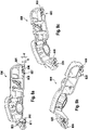
Figure 2 shows a front perspective view (Fig. 2a ), a first rear perspective view (Fig. 2b ), and an enlarged portion of a second rear perspective view (Fig. 2c ) of the supporting bracket of the electric parking brake actuator mounting assembly configured to be attached to the drum brake backplate ofFigure 1 ; -
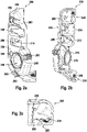
Figure 3 shows a first rear perspective view (Fig. 3a ) and a second rear perspective view (Fig. 3b ) of the electromechanical actuator of the electric parking brake actuator mounting assembly configured to be attached to the the supporting bracket ofFigure 2 ; -
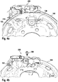
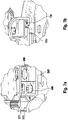
Figure 4 shows four partial perspective views relating to respective steps of attaching the supporting bracket ofFig. 2 to the brake backplate ofFigure 1 and to the electromechanical actuator ofFig. 3 ; -
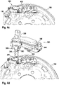
Figure 5 shows partial perspective views of a release configuration (Fig. 5a ) and of a lock configuration (Fig. 5b ) of the attachment of the electromechanical actuator ofFig. 3 to the supporting bracket ofFig. 2 attached to the brake backplate ofFigure 1 ; -
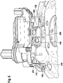
Figure 6 shows a partial perspective view of the electromechanical actuator ofFig. 3 , the supporting bracket ofFig. 2 , and the brake backplate ofFigure 1 attached to each other; -
Figure 7 shows two different enlarged portions of the view ofFig. 6 ; and -
Figure 8 shows a first rear perspective view (Fig. 8a ), a second rear perspective view (Fig. 8b ), and a third rear perspective view (Fig. 8c ) of the supporting bracket of another embodiment of the electric parking brake actuator mounting assembly according to the invention. -
Fig. 1 shows a portion of thedrum brake backplate 100 of a preferred embodiment of the electric parking brake actuator mounting assembly according to the invention; namely,Fig. 1 shows the rear surface of thedrum brake backplate 100 opposite to the front surface that is configured to be facing the brake drum when thebrake backplate 100 is installed and operative. - The rear surface of the
brake backplate 100 has asupport base 110 provided with acentral aperture 120 configured to receive thepull spindle 310 of anelectromechanical actuator 300, shown inFigs. 3 and4d ; although in the present description reference numeral "310" is used with reference to thepull spindle 310, it must be noted that it actually indicates the flexible cover, shaped as a bellow, housing the pull spindle, from which acable 312 exits (as shown inFig. 3 ), where thecable 312 is provided with anend connector 314 configured to connect the pull spindle to the actuation mechanism operating the brake shoes. Thesupport base 110 has a substantially planar support surface that obliquely protrudes from the rear surface of the brake backplate 100 (although the shape of thesupport base 110 is not an essential feature for the invention); in particular, the substantially planar support surface of thesupport base 110 is inclined with respect to the rear surface of thebrake backplate 100 by an angle of approximately 45° (again, this is not an essential feature for the invention). Two hooks 130 protrudes from the rear surface of thebrake backplate 100, optionally on opposite sides of thesupport base 110; for instance, thehooks 130 can be manufactured by stamping. Thebrake backplate 100 is also provided with a threaded throughhole 140 configured to receive a safety screw or bolt 400 (shown inFigs. 4b ,4c ,6 and7a ). Furthermore, thebrake backplate 100 has other conventional elements, such as throughholes 150 configured to receive bolts (not shown), commonly used for mounting thebrake backplate 100 on a motor vehicle, e.g. on a suspension assembly of a wheel. - The preferred embodiment of the electric parking brake actuator mounting assembly according to the invention further comprises a supporting
bracket 200, shown inFig. 2 , configured to be interposed between and attached to the rear surface of thebrake backplate 100 and theelectromechanical actuator 300. The supportingbracket 200 includes first andsecond coupling plates brake backplate 100, and anactuator mounting surface 230, configured to be coupled to and support theelectromechanical actuator 300. - The
actuator mounting surface 230 of the supportingbracket 200 is provided with aspindle seat 240 configured to receive thepull spindle 310 of theelectromechanical actuator 300; although thespindle seat 240 is circular, this is not an essential feature for the invention. Thespindle seat 240 is provided with abush 270 protruding in opposite direction to theactuator mounting surface 230 and having abush end 275 configured to touch, and optionally be supported by, thesupport base 110 of thebrake backplate 100 when the supportingbracket 200 is attached to the rear surface of thebrake backplate 100, as shown inFigs. 6 and7a . Thespindle seat 240 is laterally provided with threebayonet slots 245 which are uniformly angularly distributed around thespindle seat 240. Eachbayonet slot 245 is conventionally shaped so as to include a receiving portion and a locking portion, wherein the receiving portion has a width larger than the width of the locking portion. As shown inFig. 4d , the receiving portion is configured to receive a respective projectingelement 350 of theelectromechanical actuator 300, better shown inFig. 3 , extending laterally and parallel to thepull spindle 310 and provided with anend tooth 355 that is kept by the locking portion of therespective bayonet slot 245 below theactuator mounting surface 230 when, once that the projectingelement 350 has been inserted into the receiving portion (whereby thepull spindle 310 is inserted into the spindle seat 240), theelectromechanical actuator 300 is rotated anticlockwise about the longitudinal axis of thepull spindle 310 from a release configuration, shown inFig. 5a , to a lock configuration, shown inFig. 5b . Namely, such anticlockwise rotation of theelectromechanical actuator 300 causes the projectingelement 350 to slide from the receiving portion to the locking portion of therespective bayonet slot 245, whereby thespindle seat 240 is connected to theelectromechanical actuator 300 through a bayonet fitting such that thepull spindle 310 is kept inserted into thespindle seat 240. - Moreover, the
actuator mounting surface 230 of the supportingbracket 200 is provided with apin lock seat 250 having an external receiving portion and an internal locking portion, wherein the external receiving portion has a width larger than the width of the internal locking portion. As shown inFigs. 4d ,5 ,6 and7a , the external receiving portion is configured to receive anengagement pin 360 of theelectromechanical actuator 300, also shown inFig. 3 , that is kept in position by the internal locking portion; in particular, once that the projectingelements 350 have been inserted into the receiving portion of the respective bayonet slots 245 (whereby thepull spindle 310 is inserted into the spindle seat 240), when theelectromechanical actuator 300 is rotated anticlockwise about the longitudinal axis of thepull spindle 310 as shown fromFig. 5a to Fig. 5b , theengagement pin 360 is caused to move from the external receiving portion to the internal locking portion of thepin lock seat 250, whereby theengagement pin 360 is held by the internal locking portion of thepin lock seat 250. Advantageously, as shown inFig. 3 , theengagement pin 360 extends along an axis passing through (or in proximity to) the centre of gravity of theelectromechanical actuator 300. - Also, the
actuator mounting surface 230 of the supportingbracket 200 is provided with a snap-fit tongue 260, having anend tooth 262, and alimit stop 265, wherein the snap-fit tongue 260 and thelimit stop 265 are configured to interact with apositioning tooth 370 of theelectromechanical actuator 300 so as to implement a snap-fit connection aimed at signalling the proper positioning of theelectromechanical actuator 300 on the supportingbracket 200 and at preventing inadvertent disengagement of theelectromechanical actuator 300 from the supportingbracket 200, e.g. by hand or due to vibrations. In particular, once that the projectingelements 350 have been inserted into the receiving portion of the respective bayonet slots 245 (whereby thepull spindle 310 is inserted into the spindle seat 240), when theelectromechanical actuator 300 is rotated anticlockwise about the longitudinal axis of thepull spindle 310 as shown fromFig. 4a to Fig. 4b , thepositioning tooth 370 of theelectromechanical actuator 300 causes the snap-fit tongue 260 to elastically bend far from theelectromechanical actuator 300 until thepositioning tooth 370 reaches thelimit stop 265, whereby the snap-fit tongue 260 returns to its rest position conventionally producing the typical noise of snap fitting, thus signalling the proper positioning of theelectromechanical actuator 300 on the supportingbracket 200, and thepositioning tooth 370 stably remains between theend tooth 262 of the snap-fit tongue 260 and thelimit stop 265. - As shown in
Fig. 2 , thespindle seat 240, thepin lock seat 250 and the snap-fit tongue 260 are arranged such that thepin lock seat 250 is interposed between thespindle seat 240 and the snap-fit tongue 260. It must be noted that other embodiments of the electric parking brake actuator mounting assembly according to the invention may have a different arrangement, whereby the snap-fit tongue 260 can be interposed between thespindle seat 240 and thepin lock seat 250 or thespindle seat 240 can even be interposed between the snap-fit tongue 260 and thepin lock seat 250. - Furthermore, the
actuator mounting surface 230 of the supportingbracket 200 is provided with twoscrew seats 280, arranged in correspondence with the receiving portion of tworespective bayonet slots 245, which are configured to receive respective bolts or screws for additionally fastening theelectromechanical actuator 300 to the supportingbracket 200. However, it must be noted that other embodiments of the electric parking brake actuator mounting assembly according to the invention may be devoid ofsuch screw seats 280, and even for those embodiments having one or more screw seats similar to those indicated with thereference numerals 280 inFig. 2 , such additional fastening is not essential for the invention. - As shown in
Figs. 2b ,4a and6 , the first andsecond coupling plates bracket 200 are separated from each other by thebush 270, whereby the first andsecond coupling plates support base 110 when the supportingbracket 200 is attached to the rear surface of thebrake backplate 100. However, it must be noted that other embodiments of the electric parking brake actuator mounting assembly according to the invention may have a different number of coupling plates, for instance one single coupling plate or more than two coupling plates, shaped so as to be not interfering with thebush 270 and thesupport base 110 when the supportingbracket 200 is attached to the rear surface of thebrake backplate 100. - As shown in
Figs. 2b, 2c ,4a ,6 and7b , the first andsecond coupling plates bracket 200 are provided withrespective hook seats 220, each comprising hook positioning slots and provided with a ribbed area 225 (as clearly shown inFig. 2c ) configured to contact ahook 130 when the latter is on thehook seat 220 having suchribbed area 225. The twohook seats 220 are advantageously arranged in correspondence of two ends of the supportingbracket 200. The twohook seats 220 are reciprocally positioned according to the mutual positions of the twohooks 130 protruding from the rear surface of thebrake backplate 100. - Also, as shown in
Figs. 2a, 2b ,4a and 4b , thefirst coupling plate 205 is provided with a throughhole 215 configured to receive a safety screw or bolt 400 (shown inFigs. 4b ,4c ,6 and7a ); anaperture 290 on theactuator mounting surface 230 allows an operator to access the through hole 215 (e.g. through a screwdriver). As shown inFig. 2 , theaperture 290 is interposed between thespindle seat 240 and the pin lock seat 250 (although this is not an essential feature for the invention). The throughhole 215 is positioned with respect to the twohook seats 220 as the threaded throughhole 140 of thebrake backplate 100 is positioned with respect to the twohooks 130 of the rear surface thereof, whereby when the supportingbracket 200 is positioned on the rear surface of thebrake backplate 100 with the twohook seats 220 in correspondence of the twohooks 130, the throughhole 215 of thefirst coupling plate 205 is in correspondence of the threaded throughhole 140 of thebrake backplate 100. - The structure of the supporting
bracket 200 is conventionally provided with stiffening walls. - The first and
second coupling plates actuator mounting surface 230 by an angle of approximately 45°; however, this is not an essential feature for the invention. Also, it must be noted that other embodiments of the electric parking brake actuator mounting assembly according to the invention may have (one or more) coupling plates substantially parallel to theactuator mounting surface 230, and the (one or more) coupling plates may be joined to theactuator mounting surface 230 through one or more lateral walls. - As shown in
Fig. 4a , in order to attach the supportingbracket 200 to thebrake backplate 100, the supportingbracket 200 is first caused to slide on the rear surface of thebrake backplate 100 so as to make the twohooks 130 of the latter slide in therespective hook seats 220 of the first andsecond coupling plates bracket 200. Theribbed areas 225 ensure a matching through an interference fitting betweenhooks 130 andrespective hook seats 220 so as to take up any clearance between them and to guarantee a stable coupling under any tolerance condition. - Then, as shown in
Fig. 4b , once the supportingbracket 200 has reached the proper attachment position, the throughhole 215 of thefirst coupling plate 205 is in correspondence of the threaded throughhole 140 of thebrake backplate 100 and, as shown inFig. 4c , a safety screw or bolt 400 is screwed into the threaded throughhole 140 of thebrake backplate 100 from the throughhole 215 of the first coupling plate 205 (accessed from theaperture 290 on the actuator mounting surface 230). The safety screw or bolt 400 reliably ensures a long duration of the matching between the supportingbracket 200 and thebrake backplate 100. It must be noted that other embodiments of the electric parking brake actuator mounting assembly according to the invention may have alternative conventional fastening components for attaching the supportingbracket 200 to thebrake backplate 100, such as a rivet inserted into the throughhole 140 of the brake backplate 100 (whereby the throughhole 140 can be unthreaded). - Afterwards, an electromechanical actuator 300 (shown in
Figs. 3 and4d ) is attached to the supportingbracket 200. Theelectromechanical actuator 300 comprises apull spindle 310 extending substantially the same longitudinal axis of acap 320, from which a mechanical cable (not shown) connected to thepull spindle 310 exits, wherein thepull spindle 310 and thecap 320 extend on opposite sides of theactuator body 330. Theactuator body 330 houses an electric motor configured to move thepull spindle 310 when the electric motor is supplied by anelectric unit 340 controlled by external electrical wires (not shown). - As shown in
Figs. 4d and5a , the projectingelements 350 of theelectromechanical actuator 300 are inserted into the receiving portion of the respective bayonet slots 245 (whereby thepull spindle 310 is inserted into the spindle seat 240). - Then, the
electromechanical actuator 300 is rotated anticlockwise about the longitudinal axis of thepull spindle 310 until thepositioning tooth 370 of theelectromechanical actuator 300 reaches thelimit stop 265, as shown fromFig. 5a to Fig. 5b , whereby the projectingelements 350 are kept in therespective bayonet slots 245, theengagement pin 360 is locked in thepin lock seat 250, and thepositioning tooth 370 of theelectromechanical actuator 300 is kept between the snap-fit tongue 260 and thelimit stop 265. This final configuration is also shown inFig. 6 . - The supporting
bracket 200 is configured so as to withstand any strains caused by the operation of theelectromechanical actuator 300 and also by vibrations due to the movement of the motor vehicle, especially when theengagement pin 360 advantageously extends along an axis passing through (or in proximity to) the centre of gravity of theelectromechanical actuator 300. - It must be noted that other embodiments of the electric parking brake actuator mounting assembly according to the invention may have a different number of pairs of corresponding
hooks 130 andhook seats 220, for instance three or more hooks and three or more respective hook seats, and even only a single hook and a single respective hook seat; in the latter case, the one or more coupling plates of the supportingbracket 200 are advantageously fastened to thebrake backplate 100 by means of one or more safety screws or bolts (similar to the one indicated inFigs. 4 ,6 and7a with the reference numeral 400). - Also, in further embodiments of the invention, the
hooks 130 andhook seats 220 may be replaced with different retaining members (such as sliders) and receiving members (such as loops or rings), respectively. - Furthermore, in other embodiments of the invention, the arrangement of the hooks (or retaining members) and hook seats (or receiving members) can be exchanged between the supporting
bracket 200 and thebrake backplate 100, whereby hooks can be arranged on the latter and hook seats can be arranged on the former. In general terms, the brake backplate is provided with at least one first mechanical member and the supporting bracket is provided with respective at least one second mechanical member, wherein the at least one first mechanical member and the respective at least one second mechanical member are configured to engagedly slidably interact with each other. -
Fig. 8 shows the supportingbracket 800 of another embodiment of the electric parking brake actuator mounting assembly according to the invention, differing as follows from the supportingbracket 200 of the preferred embodiment ofFigs. 1-7 in that the hook seats 820 of the supportingbracket 800 are shaped so as to facilitate the positioning of therespective hooks 130 of the rear surface of thebrake backplate 100 on the same. In particular, the hook positioning slot of eachhook seat 820 comprises an external enlarged entry defined by opposed sloping edges to facilitate the introduction of therespective hook 130 into the hook positioning slot; in other words, as shown inFig. 8 , the plan view of the hook positioning slot of eachhook seat 820 is substantially Y-shaped. Also, eachhook seat 820 has a sliding plane portion having an increasing thickness from theexternal edge second coupling plate ribbed area 825; this is clearly shown inFig. 8a where the thickness d of theedge 806 of thefirst coupling plate 805 in correspondence with theribbed area 825 is lower than the normal thickness D of theedge 807 of thefirst coupling plate 805, namely theedge 807 far from the ribbedarea 825. As stated, both the external enlarged entry and the sliding plane portion of eachhook seat 820 facilitate sliding of the hook seats 820 beneath the respective hooks 130. - Furthermore, in the supporting
bracket 800 ofFig. 8 , theribbed area 825 of eachhook seat 820 is provided with ribs projecting upwards from the first orsecond coupling plate edge second coupling plate 805 or 810 (such that each rib defines a sort of ramp). When the hook seats 820 slide beneath therespective hooks 130, the ribs of theribbed area 825 are drawn by thehooks 130. - In any embodiment of the
invention supporting bracket bracket hooks 130 and therespective hook seats 820 is achieved, thereby also ensuring improved self-matching properties when the component mounting process started. A combined sandwich component e.g. compound of elastic steel and elastic plastics material remains possible when appropriate. Plastics material may be homogenious and integrate a certain amount of woven or non woven fiber segments e.g. fiber fabrics or fiber segments that are in maximum below 50% of the complete brackets weight. Inhomogenious concentration of fabrics, fibers or parts therefrom in heavy duty areas only remains both - positive and possible. Consequently such well integrated self interference and fitting may positively be implemented between the paired components in engagement through the inventions construction, and also a guaranteed, stable coupling under tolerance conditions is safeguarded. Dismounting of components e.g. for brake service task is also improved by the aspects described above. - Additionally, further embodiments of the electric parking brake actuator mounting assembly according to the invention may have a number of bayonet slots different from three items, e.g. for instance two or four or more, advantageously equi-angularly distributed around the
spindle seat 240 so that non-constrained variation with self aligning is achieved. - Also, in other embodiments of the invention, the
electromechanical actuator 300 may be attached to the supportingbracket 200 upon a clockwise rotation (instead of an anticlockwise rotation) about the longitudinal axis of thepull spindle 310. - Furthermore, additional embodiments of the electric parking brake actuator mounting assembly according to the invention may be devoid of any snap-fit connection between the
electromechanical actuator 300 and the supportingbracket 200, whereby neither a snap-fit tongue nor a limit stop is present on theactuator mounting surface 230 and theelectromechanical actuator 300 is devoid of any positioning tooth. - Moreover, in further embodiments of the invention, both the
hooks 130 and the hook seats 220 may be provided with respective ribbed areas configured to contact each other when thehooks 130 are on the respective hook seats 220. Alternatively, in other embodiments of the invention, neither the hooks nor the hook seats are provided with any ribbed area. In further alternative embodiments of the invention, the hook seats may be devoid of any ribbed area, while the hooks may be provided with respective ribbed areas configured to contact a hook seat when the hook having such ribbed area is on the hook seat. - The preferred embodiments of this invention have been described and a number of variations have been suggested hereinbefore, but it should be understood that those skilled in the art can make other variations and changes without so departing from the scope of protection thereof, as defined by the attached claims.
Claims (19)
- An electric parking brake actuator mounting assembly comprising an electromechanical actuator (300) that is mounted to a drum brake backplate (100),- the brake backplate (100) of the drum brake, having a rear surface opposite to a front surface configured to be facing a brake drum when the brake backplate (100) is mounted on a motor vehicle, wherein the rear surface of the brake backplate (100) includes a support base (110) configured to receive a pull spindle (310) of the electromechanical actuator (300),- a supporting bracket (200) including at least one coupling plate (205, 210), configured to be attached to the rear surface of the brake backplate (100), and an actuator mounting surface (230) configured to be coupled to and support the electromechanical actuator (300), wherein the actuator mounting surface (230) includes a spindle seat (240), configured to receive the pull spindle (310) of the electromechanical actuator (300),the electric parking brake actuator mounting assembly characterized in thatthe actuator mounting surface (230) of the supporting bracket (200) further includes a pin lock seat (250), configured to receive and lock an engagement pin (360) of the electromechanical actuator (300),the rear surface of the brake backplate (100) is provided with at least one first mechanical member (130) and said at least one coupling plate (205, 210) is provided with respective at least one second mechanical member (220), wherein said at least one first mechanical member (130) and said respective at least one second mechanical member (220) are configured to engagedly slidably interact with each other, and wherein the spindle seat (240) is configured to be connected to the electromechanical actuator (300) through a bayonet fitting including a release configuration and a lock configuration, and the pin lock seat (250) is configured to lock the engagement pin (360) when the pull spindle (310) is inserted into the spindle seat (240) and the electromechanical actuator (300) is rotated about a longitudinal axis of the pull spindle (310) from said release configuration to said lock configuration of the bayonet fitting between the spindle seat (240) and the electromechanical actuator (300).
- The electric parking brake actuator mounting assembly according to claim 1, wherein said at least one first mechanical member (130) comprises a retaining member and said respective at least one second mechanical member (220) comprises a receiving member.
- The electric parking brake actuator mounting assembly according to claim 2, wherein said retaining member is a hook (130) and said receiving member is a hook seat (220).
- The electric parking brake actuator mounting assembly according to claim 3, wherein said hook seat (220) is provided with a ribbed area (225) configured to contact said hook (130) when the latter is on the hook seat (220), whereby said hook (130) and said hook seat (220) are configured to engagedly slidably interact with each other through an interference fitting.
- The electric parking brake actuator mounting assembly according to any one of the preceding claims, wherein the spindle seat (240) is provided with a bush (270) protruding in opposite direction to the actuator mounting surface (230) and having a bush end (275) configured to touch, and optionally be supported by, the support base (110) when the supporting bracket (200) is attached to the rear surface of the brake backplate (100) .
- The electric parking brake actuator mounting assembly according to any one of the preceding claims, wherein the brake backplate (100) is provided with a threaded through hole (140) configured to receive a safety screw or bolt or rivet (400), and wherein said at least one coupling plate (205, 210) is provided with a through hole (215) configured to receive the safety screw or bolt or rivet (400), whereby the supporting bracket (200) is configured to be attached to the rear surface of the brake backplate (100) through the safety screw or bolt or rivet (400).
- The electric parking brake actuator mounting assembly according to claim 6, wherein the through hole (215) of said at least one coupling plate (205, 210) is accessible through an aperture (290) on the actuator mounting surface (230) .
- The electric parking brake actuator mounting assembly according to any one of the preceding claims, wherein the actuator mounting surface (230) is provided with a snap-fit tongue (260) and a limit stop (265), wherein the snap-fit tongue (260) and the limit stop (265) are configured to interact with a positioning tooth (370) of the electromechanical actuator (300) such that, when the electromechanical actuator (300) is rotated about the longitudinal axis of the pull spindle (310) with the pull spindle (310) inserted into the spindle seat (240) from said release configuration to said lock configuration of the bayonet fitting between the spindle seat (240) and the electromechanical actuator (300), said positioning tooth (370) is kept between the snap-fit tongue (260) and the limit stop (265) through a snap-fit connection.
- The electric parking brake actuator mounting assembly according to claim 8, wherein the pin lock seat (250) is interposed between the spindle seat (240) and the snap-fit tongue (260) on the actuator mounting surface (230).
- The electric parking brake actuator mounting assembly according to claim 9, when depending on claim 7, wherein the aperture (290) on the actuator mounting surface (230) is interposed between the spindle seat (240) and the pin lock seat (250) .
- The electric parking brake actuator mounting assembly according to any one of the preceding claims, wherein the bayonet fitting through which the spindle seat (240) is configured to be connected to the electromechanical actuator (300) is configured to allow the electromechanical actuator (300) to rotate anticlockwise about the longitudinal axis of the pull spindle (310) from said release configuration to said lock configuration of the bayonet fitting between the spindle seat (240) and the electromechanical actuator (300).
- A supporting bracket (200) of a brake backplate (100) of a drum brake, the support bracket (200) comprising- at least one coupling plate (205, 210), configured to be attached to a rear surface of the brake backplate (100),- an actuator mounting surface (230) configured to be coupled to and support an electromechanical actuator (300), wherein the actuator mounting surface (230) includes a spindle seat (240), configured to receive a pull spindle (310) of the electromechanical actuator (300), the supporting bracket (200) characterized in that the actuator mounting surface (230) further includes a pin lock seat (250), configured to receive and lock an engagement pin (360) of the electromechanical actuator (300), said at least one coupling plate (205, 210) is provided with at least one second mechanical member (220) configured to engagedly slidably interact with respective at least one first mechanical member (130), which is provided at the rear surface of the brake backplate (100) , and the spindle seat (240) is configured to be connected to the electromechanical actuator (300) through a bayonet fitting including a release configuration and a lock configuration, and the pin lock seat (250) is configured to lock the engagement pin (360) when the pull spindle (310) is inserted into the spindle seat (240) and the electromechanical actuator (300) is rotated about a longitudinal axis of the pull spindle (310) from said release configuration to said lock configuration of the bayonet fitting between the spindle seat (240) and the electromechanical actuator (300).
- The supporting bracket (200) according to claim 12, wherein said respective at least one second mechanical member (220) comprises a hook seat (220) configured to engagedly slidably interact with a hook (130) of the rear surface of the brake backplate (100).
- The supporting bracket (200, 800) according to claims 12 or 13 wherein at least the bracket (200, 800) is made from elastic steel and/or plastics material, or a combined sandwich component especially compound of elastic steel and elastic plastics material.
- The supporting bracket (200,800) according to claim 14 wherein the plastics material integrates a certain amount of woven or non woven fiber especially a fiber fabric or fiber segments that are in maximum below 50 % of the complete bracket weight.
- A brake backplate (100) of a drum brake, having a rear surface opposite to a front surface configured to be facing a brake drum when the brake backplate (100) is mounted on a motor vehicle,wherein the rear surface of the brake backplate (100) includes a support base (110) configured to receive a pull spindle (310) of an electromechanical actuator (300),the brake backplate (100) characterized in thatthe brake backplate (100) is provided with at least one first mechanical member (130) configured to engagedly slidably interact with respective at least one second mechanical member (220) of at least one coupling plate (205, 210) of a supporting bracket (200).
- The brake backplate (100) according to claim 15, wherein said at least one first mechanical member (130) comprises a hook (130) configured to engagedly slidably interact with a hook seat (220) of said at least one coupling plate (205, 210) of the supporting bracket (200).
- A process for mounting an electromechanical actuator (300) on the electric parking brake actuator mounting assembly according to any one of claims 1 to 11, characterized in that the electromechanical actuator (300) includes a pull spindle (310), having a longitudinal axis, and an engagement pin (360), the process comprising the following steps:A. inserting the pull spindle (310) into the spindle seat (240) according to said release configuration of the bayonet fitting between the spindle seat (240) and the electromechanical actuator (300); andB. rotating the electromechanical actuator (300) about a longitudinal axis of the pull spindle (310) from said release configuration to said lock configuration of the bayonet fitting between the spindle seat (240) and the electromechanical actuator (300), whereby the electromechanical actuator (300) is rotated until the pin lock seat (250) receives and locks the engagement pin (360).
- The process according to claim 18, further comprising the preliminary step of causing the supporting bracket (200) to slide on the rear surface of the brake backplate (100) up to reaching an attachment position at which said at least one first mechanical member (130) and said respective at least one second mechanical member (220) engagedly slidably interact with each other.
Applications Claiming Priority (1)
| Application Number | Priority Date | Filing Date | Title |
|---|---|---|---|
| PCT/EP2018/054529 WO2019161916A1 (en) | 2018-02-23 | 2018-02-23 | Electric parking brake actuator mounting assembly |
Publications (2)
| Publication Number | Publication Date |
|---|---|
| EP3755590A1 EP3755590A1 (en) | 2020-12-30 |
| EP3755590B1 true EP3755590B1 (en) | 2023-01-11 |
Family
ID=61581245
Family Applications (1)
| Application Number | Title | Priority Date | Filing Date |
|---|---|---|---|
| EP18709285.3A Active EP3755590B1 (en) | 2018-02-23 | 2018-02-23 | Electric parking brake actuator mounting assembly, supporting bracket, brake backplate and a process for mounting |
Country Status (4)
| Country | Link |
|---|---|
| US (1) | US11913509B2 (en) |
| EP (1) | EP3755590B1 (en) |
| CN (1) | CN111819121B (en) |
| WO (1) | WO2019161916A1 (en) |
Cited By (1)
| Publication number | Priority date | Publication date | Assignee | Title |
|---|---|---|---|---|
| DE102024205665A1 (en) * | 2024-06-19 | 2025-12-24 | Continental Automotive Technologies GmbH | Electric wheel brake unit assembly with efficient assembly method |
Citations (1)
| Publication number | Priority date | Publication date | Assignee | Title |
|---|---|---|---|---|
| WO2017097696A1 (en) * | 2015-12-10 | 2017-06-15 | Continental Teves Ag & Co. Ohg | Electric drum brake system having a rationalized electric parking brake actuator |
Family Cites Families (26)
| Publication number | Priority date | Publication date | Assignee | Title |
|---|---|---|---|---|
| DE696200C (en) * | 1939-07-14 | 1941-03-06 | Porsche Kg | Shoe brake, especially for motor vehicles |
| US4673069A (en) * | 1986-03-18 | 1987-06-16 | General Motors Corporation | Wheel cylinder mounting arrangement |
| US5044475A (en) * | 1990-04-27 | 1991-09-03 | Eaton Corporation | Rotary drum brake assembly bracket |
| US5310026A (en) | 1992-10-19 | 1994-05-10 | General Motors Corporation | Electric drum brake |
| JP2001173694A (en) * | 1999-12-16 | 2001-06-26 | Nisshinbo Ind Inc | Brake cable attachment device for drum brake |
| JP2001323955A (en) * | 2000-05-18 | 2001-11-22 | Nisshinbo Ind Inc | Brake cable connection device for drum brake |
| BRPI0212908A2 (en) * | 2001-09-21 | 2017-05-02 | H Petrak Gregory | Method and apparatus for tensioning an emergency brake system in a vehicle. |
| AU2003267564A1 (en) * | 2002-09-11 | 2004-04-30 | Automotive Products Italia (Sv) S.P.A. | Parking brake of a drum brake |
| DE102004049434A1 (en) | 2004-01-21 | 2005-10-06 | Continental Teves Ag & Co. Ohg | Electromechanically actuated parking brake |
| US20080135349A1 (en) * | 2004-06-04 | 2008-06-12 | Goodrich Corporation | Electric Brake for Aircraft |
| EP1645765B1 (en) * | 2004-10-06 | 2018-09-12 | BorgWarner, Inc. | Power transmission assembly |
| DE112006002895B4 (en) | 2005-10-31 | 2021-12-16 | ZF Active Safety US lnc. | Electrical actuator for a vehicle brake assembly |
| US7963154B2 (en) * | 2006-08-30 | 2011-06-21 | Kistler Holding Ag | Sensor unit for the measurment of a variable in a medium |
| EP2147226B1 (en) * | 2007-05-21 | 2013-07-03 | Goodrich Corporation | Repair of electric aircraft brake |
| CN103339401B (en) * | 2011-02-02 | 2017-02-15 | 大陆-特韦斯贸易合伙股份公司及两合公司 | Drum brake module which can be operated by electric motor |
| JP5844630B2 (en) * | 2011-12-14 | 2016-01-20 | 曙ブレーキ工業株式会社 | Drum brake type electric parking brake device |
| KR101920677B1 (en) * | 2012-05-03 | 2018-11-21 | 현대모비스 주식회사 | Electronic parking brake apparatus |
| DE102013210528A1 (en) * | 2013-06-06 | 2014-12-11 | Continental Teves Ag & Co. Ohg | Electrically actuated drum brake |
| DE102013217065C5 (en) * | 2013-08-27 | 2022-11-17 | Saf-Holland Gmbh | brake unit |
| DE102014204769A1 (en) * | 2013-12-06 | 2015-06-11 | Continental Teves Ag & Co. Ohg | Electromotive operable drum brake module |
| FR3016010B1 (en) * | 2013-12-30 | 2016-02-12 | Chassis Brakes Int Bv | DRUM BRAKE DEVICE INCLUDING PARKING BRAKE OPERATING IN DUO SERVO MODE, VEHICLE AND ASSOCIATED ASSEMBLY METHODS |
| ES2735997T3 (en) | 2014-03-21 | 2019-12-23 | Ims Gear Se & Co Kgaa | Actuator Arrangement |
| EP3163113B1 (en) * | 2014-06-26 | 2020-06-03 | Akebono Brake Industry Co., Ltd. | Drum brake device |
| CN203902208U (en) * | 2014-06-27 | 2014-10-29 | 安徽江淮汽车股份有限公司 | Automobile foot blowing air duct cover plate and automobile foot blowing air duct mounting structure |
| US9303703B2 (en) * | 2014-07-09 | 2016-04-05 | Bendix Spicer Foundation Brake Llc | Bracket assembly for mounting a brake assembly and brake actuator |
| JP6727178B2 (en) * | 2017-10-10 | 2020-07-22 | 日信工業株式会社 | Electric parking brake device |
-
2018
- 2018-02-23 CN CN201880089983.7A patent/CN111819121B/en active Active
- 2018-02-23 EP EP18709285.3A patent/EP3755590B1/en active Active
- 2018-02-23 WO PCT/EP2018/054529 patent/WO2019161916A1/en not_active Ceased
-
2020
- 2020-08-17 US US16/994,833 patent/US11913509B2/en active Active
Patent Citations (1)
| Publication number | Priority date | Publication date | Assignee | Title |
|---|---|---|---|---|
| WO2017097696A1 (en) * | 2015-12-10 | 2017-06-15 | Continental Teves Ag & Co. Ohg | Electric drum brake system having a rationalized electric parking brake actuator |
Cited By (2)
| Publication number | Priority date | Publication date | Assignee | Title |
|---|---|---|---|---|
| DE102024205665A1 (en) * | 2024-06-19 | 2025-12-24 | Continental Automotive Technologies GmbH | Electric wheel brake unit assembly with efficient assembly method |
| WO2025262145A1 (en) | 2024-06-19 | 2025-12-26 | Aumovio Germany Gmbh | Electric wheel brake unit composition including effective unit assembly process |
Also Published As
| Publication number | Publication date |
|---|---|
| CN111819121B (en) | 2023-07-28 |
| US20200378460A1 (en) | 2020-12-03 |
| US11913509B2 (en) | 2024-02-27 |
| CN111819121A (en) | 2020-10-23 |
| EP3755590A1 (en) | 2020-12-30 |
| WO2019161916A1 (en) | 2019-08-29 |
Similar Documents
| Publication | Publication Date | Title |
|---|---|---|
| US11078974B2 (en) | Disc brake for a commercial vehicle | |
| US6427810B2 (en) | Spot-type disc brake for an automotive vehicle | |
| CN103161852B (en) | Drum brake type electric parking and braking device | |
| US8016084B2 (en) | Brake pad for a disc brake | |
| US8496093B2 (en) | Brake pad of a disc brake | |
| KR20150056836A (en) | Arrangement of a pad retaining clip on the brake caliper of a disk brake, and brake pad | |
| KR100619536B1 (en) | Brake shoe and brake assembly | |
| RU2699955C1 (en) | Disc brake for utility vehicle, brake pad and brake pad kit | |
| WO2014118260A1 (en) | Friction lining with a steel wire bow spring | |
| EP1055528A1 (en) | Brake device with brake adjustment system | |
| CN106104057B (en) | Suitable for including the drum brake apparatus of parking brake that is traditional or being run under double servo patterns | |
| US11913509B2 (en) | Electric parking brake actuator mounting assembly | |
| CA1275431C (en) | Booster mount | |
| US10876328B2 (en) | Door handle assembly for a motor vehicle | |
| JPS6325874Y2 (en) | ||
| CN115929817A (en) | Brake clip and apparatus for a disc brake assembly | |
| US20030019696A1 (en) | Parking brake device including pivotable brake lever which extends through aperture of backing plate | |
| JP2013228011A (en) | Parking brake mechanism and electric parking brake | |
| US20030047393A1 (en) | Mechanical release for parking brake cable system | |
| KR20240036633A (en) | Disc brakes for utility vehicles and brake linings for disc brakes | |
| CN206111908U (en) | Car adjustment arm with anti -lock function | |
| KR101669633B1 (en) | Mountain brackets for monobloc foot parking brake | |
| EP1792096A1 (en) | Brake carrier having improved electromechanical actuator and mounting arrangement therefor | |
| JP3524506B2 (en) | Clutch operating device | |
| US20250382998A1 (en) | Disc brake, securing elements and retaining bracket therefor |
Legal Events
| Date | Code | Title | Description |
|---|---|---|---|
| STAA | Information on the status of an ep patent application or granted ep patent |
Free format text: STATUS: UNKNOWN |
|
| STAA | Information on the status of an ep patent application or granted ep patent |
Free format text: STATUS: THE INTERNATIONAL PUBLICATION HAS BEEN MADE |
|
| PUAI | Public reference made under article 153(3) epc to a published international application that has entered the european phase |
Free format text: ORIGINAL CODE: 0009012 |
|
| STAA | Information on the status of an ep patent application or granted ep patent |
Free format text: STATUS: REQUEST FOR EXAMINATION WAS MADE |
|
| 17P | Request for examination filed |
Effective date: 20200923 |
|
| AK | Designated contracting states |
Kind code of ref document: A1 Designated state(s): AL AT BE BG CH CY CZ DE DK EE ES FI FR GB GR HR HU IE IS IT LI LT LU LV MC MK MT NL NO PL PT RO RS SE SI SK SM TR |
|
| AX | Request for extension of the european patent |
Extension state: BA ME |
|
| DAV | Request for validation of the european patent (deleted) | ||
| DAX | Request for extension of the european patent (deleted) | ||
| RAP1 | Party data changed (applicant data changed or rights of an application transferred) |
Owner name: CONTINENTAL AUTOMOTIVE TECHNOLOGIES GMBH |
|
| RIC1 | Information provided on ipc code assigned before grant |
Ipc: F16D 51/00 20060101ALN20220714BHEP Ipc: F16D 121/18 20120101ALN20220714BHEP Ipc: F16D 121/14 20120101ALN20220714BHEP Ipc: F16D 65/22 20060101ALI20220714BHEP Ipc: B60T 1/06 20060101ALI20220714BHEP Ipc: B60T 13/74 20060101AFI20220714BHEP |
|
| GRAP | Despatch of communication of intention to grant a patent |
Free format text: ORIGINAL CODE: EPIDOSNIGR1 |
|
| STAA | Information on the status of an ep patent application or granted ep patent |
Free format text: STATUS: GRANT OF PATENT IS INTENDED |
|
| INTG | Intention to grant announced |
Effective date: 20220913 |
|
| GRAS | Grant fee paid |
Free format text: ORIGINAL CODE: EPIDOSNIGR3 |
|
| GRAA | (expected) grant |
Free format text: ORIGINAL CODE: 0009210 |
|
| STAA | Information on the status of an ep patent application or granted ep patent |
Free format text: STATUS: THE PATENT HAS BEEN GRANTED |
|
| AK | Designated contracting states |
Kind code of ref document: B1 Designated state(s): AL AT BE BG CH CY CZ DE DK EE ES FI FR GB GR HR HU IE IS IT LI LT LU LV MC MK MT NL NO PL PT RO RS SE SI SK SM TR |
|
| REG | Reference to a national code |
Ref country code: GB Ref legal event code: FG4D |
|
| REG | Reference to a national code |
Ref country code: CH Ref legal event code: EP |
|
| REG | Reference to a national code |
Ref country code: DE Ref legal event code: R096 Ref document number: 602018045270 Country of ref document: DE |
|
| REG | Reference to a national code |
Ref country code: IE Ref legal event code: FG4D |
|
| REG | Reference to a national code |
Ref country code: AT Ref legal event code: REF Ref document number: 1543258 Country of ref document: AT Kind code of ref document: T Effective date: 20230215 |
|
| REG | Reference to a national code |
Ref country code: LT Ref legal event code: MG9D |
|
| REG | Reference to a national code |
Ref country code: NL Ref legal event code: MP Effective date: 20230111 |
|
| REG | Reference to a national code |
Ref country code: AT Ref legal event code: MK05 Ref document number: 1543258 Country of ref document: AT Kind code of ref document: T Effective date: 20230111 |
|
| P01 | Opt-out of the competence of the unified patent court (upc) registered |
Effective date: 20230522 |
|
| PG25 | Lapsed in a contracting state [announced via postgrant information from national office to epo] |
Ref country code: NL Free format text: LAPSE BECAUSE OF FAILURE TO SUBMIT A TRANSLATION OF THE DESCRIPTION OR TO PAY THE FEE WITHIN THE PRESCRIBED TIME-LIMIT Effective date: 20230111 |
|
| PG25 | Lapsed in a contracting state [announced via postgrant information from national office to epo] |
Ref country code: RS Free format text: LAPSE BECAUSE OF FAILURE TO SUBMIT A TRANSLATION OF THE DESCRIPTION OR TO PAY THE FEE WITHIN THE PRESCRIBED TIME-LIMIT Effective date: 20230111 Ref country code: PT Free format text: LAPSE BECAUSE OF FAILURE TO SUBMIT A TRANSLATION OF THE DESCRIPTION OR TO PAY THE FEE WITHIN THE PRESCRIBED TIME-LIMIT Effective date: 20230511 Ref country code: NO Free format text: LAPSE BECAUSE OF FAILURE TO SUBMIT A TRANSLATION OF THE DESCRIPTION OR TO PAY THE FEE WITHIN THE PRESCRIBED TIME-LIMIT Effective date: 20230411 Ref country code: LV Free format text: LAPSE BECAUSE OF FAILURE TO SUBMIT A TRANSLATION OF THE DESCRIPTION OR TO PAY THE FEE WITHIN THE PRESCRIBED TIME-LIMIT Effective date: 20230111 Ref country code: LT Free format text: LAPSE BECAUSE OF FAILURE TO SUBMIT A TRANSLATION OF THE DESCRIPTION OR TO PAY THE FEE WITHIN THE PRESCRIBED TIME-LIMIT Effective date: 20230111 Ref country code: HR Free format text: LAPSE BECAUSE OF FAILURE TO SUBMIT A TRANSLATION OF THE DESCRIPTION OR TO PAY THE FEE WITHIN THE PRESCRIBED TIME-LIMIT Effective date: 20230111 Ref country code: ES Free format text: LAPSE BECAUSE OF FAILURE TO SUBMIT A TRANSLATION OF THE DESCRIPTION OR TO PAY THE FEE WITHIN THE PRESCRIBED TIME-LIMIT Effective date: 20230111 Ref country code: AT Free format text: LAPSE BECAUSE OF FAILURE TO SUBMIT A TRANSLATION OF THE DESCRIPTION OR TO PAY THE FEE WITHIN THE PRESCRIBED TIME-LIMIT Effective date: 20230111 |
|
| PG25 | Lapsed in a contracting state [announced via postgrant information from national office to epo] |
Ref country code: SE Free format text: LAPSE BECAUSE OF FAILURE TO SUBMIT A TRANSLATION OF THE DESCRIPTION OR TO PAY THE FEE WITHIN THE PRESCRIBED TIME-LIMIT Effective date: 20230111 Ref country code: PL Free format text: LAPSE BECAUSE OF FAILURE TO SUBMIT A TRANSLATION OF THE DESCRIPTION OR TO PAY THE FEE WITHIN THE PRESCRIBED TIME-LIMIT Effective date: 20230111 Ref country code: IS Free format text: LAPSE BECAUSE OF FAILURE TO SUBMIT A TRANSLATION OF THE DESCRIPTION OR TO PAY THE FEE WITHIN THE PRESCRIBED TIME-LIMIT Effective date: 20230511 Ref country code: GR Free format text: LAPSE BECAUSE OF FAILURE TO SUBMIT A TRANSLATION OF THE DESCRIPTION OR TO PAY THE FEE WITHIN THE PRESCRIBED TIME-LIMIT Effective date: 20230412 Ref country code: FI Free format text: LAPSE BECAUSE OF FAILURE TO SUBMIT A TRANSLATION OF THE DESCRIPTION OR TO PAY THE FEE WITHIN THE PRESCRIBED TIME-LIMIT Effective date: 20230111 |
|
| REG | Reference to a national code |
Ref country code: CH Ref legal event code: PL |
|
| REG | Reference to a national code |
Ref country code: DE Ref legal event code: R097 Ref document number: 602018045270 Country of ref document: DE |
|
| REG | Reference to a national code |
Ref country code: BE Ref legal event code: MM Effective date: 20230228 |
|
| PG25 | Lapsed in a contracting state [announced via postgrant information from national office to epo] |
Ref country code: SM Free format text: LAPSE BECAUSE OF FAILURE TO SUBMIT A TRANSLATION OF THE DESCRIPTION OR TO PAY THE FEE WITHIN THE PRESCRIBED TIME-LIMIT Effective date: 20230111 Ref country code: RO Free format text: LAPSE BECAUSE OF FAILURE TO SUBMIT A TRANSLATION OF THE DESCRIPTION OR TO PAY THE FEE WITHIN THE PRESCRIBED TIME-LIMIT Effective date: 20230111 Ref country code: MC Free format text: LAPSE BECAUSE OF FAILURE TO SUBMIT A TRANSLATION OF THE DESCRIPTION OR TO PAY THE FEE WITHIN THE PRESCRIBED TIME-LIMIT Effective date: 20230111 Ref country code: LU Free format text: LAPSE BECAUSE OF NON-PAYMENT OF DUE FEES Effective date: 20230223 Ref country code: LI Free format text: LAPSE BECAUSE OF NON-PAYMENT OF DUE FEES Effective date: 20230228 Ref country code: EE Free format text: LAPSE BECAUSE OF FAILURE TO SUBMIT A TRANSLATION OF THE DESCRIPTION OR TO PAY THE FEE WITHIN THE PRESCRIBED TIME-LIMIT Effective date: 20230111 Ref country code: DK Free format text: LAPSE BECAUSE OF FAILURE TO SUBMIT A TRANSLATION OF THE DESCRIPTION OR TO PAY THE FEE WITHIN THE PRESCRIBED TIME-LIMIT Effective date: 20230111 Ref country code: CZ Free format text: LAPSE BECAUSE OF FAILURE TO SUBMIT A TRANSLATION OF THE DESCRIPTION OR TO PAY THE FEE WITHIN THE PRESCRIBED TIME-LIMIT Effective date: 20230111 Ref country code: CH Free format text: LAPSE BECAUSE OF NON-PAYMENT OF DUE FEES Effective date: 20230228 |
|
| PLBE | No opposition filed within time limit |
Free format text: ORIGINAL CODE: 0009261 |
|
| STAA | Information on the status of an ep patent application or granted ep patent |
Free format text: STATUS: NO OPPOSITION FILED WITHIN TIME LIMIT |
|
| PG25 | Lapsed in a contracting state [announced via postgrant information from national office to epo] |
Ref country code: SK Free format text: LAPSE BECAUSE OF FAILURE TO SUBMIT A TRANSLATION OF THE DESCRIPTION OR TO PAY THE FEE WITHIN THE PRESCRIBED TIME-LIMIT Effective date: 20230111 |
|
| 26N | No opposition filed |
Effective date: 20231012 |
|
| REG | Reference to a national code |
Ref country code: IE Ref legal event code: MM4A |
|
| GBPC | Gb: european patent ceased through non-payment of renewal fee |
Effective date: 20230411 |
|
| PG25 | Lapsed in a contracting state [announced via postgrant information from national office to epo] |
Ref country code: GB Free format text: LAPSE BECAUSE OF NON-PAYMENT OF DUE FEES Effective date: 20230411 |
|
| PG25 | Lapsed in a contracting state [announced via postgrant information from national office to epo] |
Ref country code: SI Free format text: LAPSE BECAUSE OF FAILURE TO SUBMIT A TRANSLATION OF THE DESCRIPTION OR TO PAY THE FEE WITHIN THE PRESCRIBED TIME-LIMIT Effective date: 20230111 Ref country code: IE Free format text: LAPSE BECAUSE OF NON-PAYMENT OF DUE FEES Effective date: 20230223 Ref country code: GB Free format text: LAPSE BECAUSE OF NON-PAYMENT OF DUE FEES Effective date: 20230411 |
|
| REG | Reference to a national code |
Ref country code: DE Ref legal event code: R081 Ref document number: 602018045270 Country of ref document: DE Owner name: CONTINENTAL AUTOMOTIVE TECHNOLOGIES GMBH, DE Free format text: FORMER OWNER: CONTINENTAL AUTOMOTIVE TECHNOLOGIES GMBH, 30165 HANNOVER, DE Ref country code: DE Ref legal event code: R081 Ref document number: 602018045270 Country of ref document: DE Owner name: AUMOVIO GERMANY GMBH, DE Free format text: FORMER OWNER: CONTINENTAL AUTOMOTIVE TECHNOLOGIES GMBH, 30165 HANNOVER, DE |
|
| PG25 | Lapsed in a contracting state [announced via postgrant information from national office to epo] |
Ref country code: BE Free format text: LAPSE BECAUSE OF NON-PAYMENT OF DUE FEES Effective date: 20230228 |
|
| PG25 | Lapsed in a contracting state [announced via postgrant information from national office to epo] |
Ref country code: BG Free format text: LAPSE BECAUSE OF FAILURE TO SUBMIT A TRANSLATION OF THE DESCRIPTION OR TO PAY THE FEE WITHIN THE PRESCRIBED TIME-LIMIT Effective date: 20230111 |
|
| PG25 | Lapsed in a contracting state [announced via postgrant information from national office to epo] |
Ref country code: BG Free format text: LAPSE BECAUSE OF FAILURE TO SUBMIT A TRANSLATION OF THE DESCRIPTION OR TO PAY THE FEE WITHIN THE PRESCRIBED TIME-LIMIT Effective date: 20230111 |
|
| PG25 | Lapsed in a contracting state [announced via postgrant information from national office to epo] |
Ref country code: CY Free format text: LAPSE BECAUSE OF FAILURE TO SUBMIT A TRANSLATION OF THE DESCRIPTION OR TO PAY THE FEE WITHIN THE PRESCRIBED TIME-LIMIT; INVALID AB INITIO Effective date: 20180223 |
|
| PG25 | Lapsed in a contracting state [announced via postgrant information from national office to epo] |
Ref country code: HU Free format text: LAPSE BECAUSE OF FAILURE TO SUBMIT A TRANSLATION OF THE DESCRIPTION OR TO PAY THE FEE WITHIN THE PRESCRIBED TIME-LIMIT; INVALID AB INITIO Effective date: 20180223 |
|
| PG25 | Lapsed in a contracting state [announced via postgrant information from national office to epo] |
Ref country code: TR Free format text: LAPSE BECAUSE OF FAILURE TO SUBMIT A TRANSLATION OF THE DESCRIPTION OR TO PAY THE FEE WITHIN THE PRESCRIBED TIME-LIMIT Effective date: 20230111 |
|
| REG | Reference to a national code |
Ref country code: DE Ref legal event code: R081 Ref document number: 602018045270 Country of ref document: DE Owner name: AUMOVIO GERMANY GMBH, DE Free format text: FORMER OWNER: CONTINENTAL AUTOMOTIVE TECHNOLOGIES GMBH, 30175 HANNOVER, DE |
|
| PGFP | Annual fee paid to national office [announced via postgrant information from national office to epo] |
Ref country code: DE Payment date: 20260228 Year of fee payment: 9 |
|
| PGFP | Annual fee paid to national office [announced via postgrant information from national office to epo] |
Ref country code: IT Payment date: 20260220 Year of fee payment: 9 |
|
| PGFP | Annual fee paid to national office [announced via postgrant information from national office to epo] |
Ref country code: FR Payment date: 20260227 Year of fee payment: 9 |