EP3755064A1 - Neighbour relationship establishment method, wireless relay and network-side node - Google Patents
Neighbour relationship establishment method, wireless relay and network-side node Download PDFInfo
- Publication number
- EP3755064A1 EP3755064A1 EP19754808.4A EP19754808A EP3755064A1 EP 3755064 A1 EP3755064 A1 EP 3755064A1 EP 19754808 A EP19754808 A EP 19754808A EP 3755064 A1 EP3755064 A1 EP 3755064A1
- Authority
- EP
- European Patent Office
- Prior art keywords
- wireless relay
- relay
- wireless
- network side
- side node
- Prior art date
- Legal status (The legal status is an assumption and is not a legal conclusion. Google has not performed a legal analysis and makes no representation as to the accuracy of the status listed.)
- Granted
Links
Images

Classifications
-
- H—ELECTRICITY
- H04—ELECTRIC COMMUNICATION TECHNIQUE
- H04W—WIRELESS COMMUNICATION NETWORKS
- H04W40/00—Communication routing or communication path finding
- H04W40/02—Communication route or path selection, e.g. power-based or shortest path routing
- H04W40/22—Communication route or path selection, e.g. power-based or shortest path routing using selective relaying for reaching a BTS [Base Transceiver Station] or an access point
-
- H—ELECTRICITY
- H04—ELECTRIC COMMUNICATION TECHNIQUE
- H04W—WIRELESS COMMUNICATION NETWORKS
- H04W12/00—Security arrangements; Authentication; Protecting privacy or anonymity
- H04W12/06—Authentication
-
- H—ELECTRICITY
- H04—ELECTRIC COMMUNICATION TECHNIQUE
- H04W—WIRELESS COMMUNICATION NETWORKS
- H04W12/00—Security arrangements; Authentication; Protecting privacy or anonymity
- H04W12/08—Access security
-
- H—ELECTRICITY
- H04—ELECTRIC COMMUNICATION TECHNIQUE
- H04W—WIRELESS COMMUNICATION NETWORKS
- H04W48/00—Access restriction; Network selection; Access point selection
- H04W48/16—Discovering, processing access restriction or access information
-
- H—ELECTRICITY
- H04—ELECTRIC COMMUNICATION TECHNIQUE
- H04W—WIRELESS COMMUNICATION NETWORKS
- H04W76/00—Connection management
- H04W76/10—Connection setup
-
- H—ELECTRICITY
- H04—ELECTRIC COMMUNICATION TECHNIQUE
- H04W—WIRELESS COMMUNICATION NETWORKS
- H04W84/00—Network topologies
- H04W84/02—Hierarchically pre-organised networks, e.g. paging networks, cellular networks, WLAN [Wireless Local Area Network] or WLL [Wireless Local Loop]
- H04W84/04—Large scale networks; Deep hierarchical networks
- H04W84/042—Public Land Mobile systems, e.g. cellular systems
- H04W84/047—Public Land Mobile systems, e.g. cellular systems using dedicated repeater stations
-
- H—ELECTRICITY
- H04—ELECTRIC COMMUNICATION TECHNIQUE
- H04W—WIRELESS COMMUNICATION NETWORKS
- H04W88/00—Devices specially adapted for wireless communication networks, e.g. terminals, base stations or access point devices
- H04W88/02—Terminal devices
- H04W88/04—Terminal devices adapted for relaying to or from another terminal or user
Definitions
- the present disclosure relates to the field of communications technologies, in particular to a neighboring relationship establishment method, a wireless relay and a network side node.
- a wireless relay backhaul technology includes the use of a wireless backhaul link at a high frequency band of more than 6GHz.
- Relay wireless relay
- one or more wireless relay nodes is added between a network side node and a terminal, so as to relay a wireless signal for one or more times, i.e., usually the wireless signal can reach the terminal in a multi-hop manner.
- a link from the network side node to the terminal is divided into two links, i.e., a link from the network side node to a relay and a link from the relay to the terminal, and this gives an opportunity to replace a link with inferior quality with two links each with superior quality, so as to acquire a higher link capacity and a better coverage.
- An object of the present disclosure is to provide a neighboring relationship establishment method, a wireless relay and a network side node, so as to rapidly recover data transmission when a backhaul path is interrupted.
- the present disclosure provides in an embodiment a neighboring relationship establishment method for a first wireless relay, including: establishing a neighbor list for the first wireless relay, the neighbor list including at least one neighbor relay of the first wireless relay, the neighbor relay being a wireless relay whose signal quality detected by the first wireless relay meets a predetermined condition; and establishing an interface between the first wireless relay and the neighbor relay.
- the present disclosure provides in an embodiment a neighboring relationship establishment method for a network side node, including: receiving, by the network side node, a first connection request message transmitted from a first wireless relay, the first connection request message carrying identification information for authenticating a relay identity of the first wireless relay; and after the relay identity of the first wireless relay has been authenticated successfully, transmitting a first connection establishment message to the first wireless relay, to establish an interface between the network side node and the first wireless relay.
- the present disclosure provides in an embodiment a first wireless relay, including: a neighboring relationship establishment unit used to establish a neighbor list for the first wireless relay, the neighbor list including at least one neighbor relay of the first wireless relay, the neighbor relay being a wireless relay whose signal quality detected by the first wireless relay meets a predetermined condition; and a neighboring interface establishment unit used to establish an interface between the first wireless relay and the neighbor relay.
- the present disclosure provides in an embodiment a first wireless relay, including a processor, a memory, and a computer program stored in the memory and capable of being executed by the processor.
- the processor is used to execute the computer program so as to implement steps of the above-mentioned neighboring relationship establishment method.
- the present disclosure provides in an embodiment a network side node, including: a first request reception unit used to receive a first connection request message transmitted from a first wireless relay, the first connection request message carrying identification information for authenticating a relay identity of the first wireless relay; and a first interface establishment unit used to, after the relay identity of the first wireless relay has been authenticated successfully, transmit a first connection establishment message to the first wireless relay, to establish an interface between the network side node and the first wireless relay.
- the present disclosure provides in an embodiment a network side node, including a processor, a memory, and a computer program stored in the memory and capable of being executed by the processor.
- the processor is used to execute the computer program to implement steps of the above-mentioned neighboring relationship establishment method.
- the present disclosure provides in an embodiment a computer-readable storage medium storing therein a computer program.
- the computer program is executed by a processor to implement steps of the above-mentioned neighboring relationship establishment method.
- the wireless relay and the network side node in the embodiments of the present disclosure through establishing the neighbor list for the first wireless relay and establishing the interface between the first wireless relay and the neighbor relay, it is able to establish and maintain the neighboring relationship between the wireless relays.
- a network side node will not be particularly defined, and it may be a macro base station (Macro Base Station), a pico base station (Pico Base Station), a Node B (3 rd -Generation (3G) base station), an evolved Node B (eNB), a Femto eNB (or Home eNode B or Home eNB or HeNB), a relay, an access point, a remote radio unit (Remote Radio Unit, RRU), a remote radio head (Remote Radio Head, RRH), or a network side node in a 5G mobile communications system, e.g., a central unit (Central Unit, CU) or a distributed unit (Distributed Unit, DU) of a base station (gNB).
- a 5G mobile communications system e.g., a central unit (Central Unit, CU) or a distributed unit (Distributed Unit, DU) of a base station (gNB).
- a terminal in the embodiments of the present disclosure may be a mobile phone (or cellular phone) or another device capable of transmitting or receiving a radio signal, including a User Equipment (UE), a Personal Digital Assistant (PDA), a wireless modem, a wireless communication device, a handheld device, a laptop computer, a cordless telephone, a Wireless Local Loop (WLL) station, a customer premise equipment (Customer Premise Equipment, CPE) capable of converting a mobile communication signal into a WiFi signal, a mobile smart hotspot, smart appliance, or another device capable of spontaneously communicating with a mobile communication network without manual operation.
- UE User Equipment
- PDA Personal Digital Assistant
- WLL Wireless Local Loop
- CPE Customer Premise Equipment
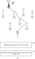
- Fig. 1 shows an example of a multi-hop wireless relay backhaul path.
- a wireless backhaul network consists of wireless relays 1 to 7.
- the wireless backhaul network includes a plurality of wireless relays, parts of which may directly communicate with a network side node, and parts of which may communicate with the network side node via the other wireless relays. Based on these wireless relays, it is able to establish a backhaul path from the network side node to a terminal.
- each wireless relay in Fig.1 may be called as integrated access and backhaul (Integrated Access and Backhaul, IAB).
- IAB may have a complete base station function, or merely have a data forwarding function similar to the base station.
- the network side node with wired interface connection is just the base station, which may also be called as donor Integrated Access and Backhaul (DIAB).
- DIAB donor Integrated Access and Backhaul
- the IABs may also communicate with each other via a wireless interface.
- an IAB to which the terminal accesses and which is directly used to provide services to the terminal (UE) may be called as a serving IAB (Serving IAB, SIAB).
- a prior-hop IAB of the SIAB may be called as NIAB (Next IAB).
- the use of a wireless relay as a node device of a backhaul network is currently being studied, so as to create the backhaul network.
- a neighboring relationship establishment method for a first wireless relay in a backhaul network which, as shown in Fig.2 , includes the following steps.
- Step 21 establishing a neighbor list for the first wireless relay, the neighbor list including at least one neighbor relay of the first wireless relay, the neighbor relay being a wireless relay whose signal quality detected by the first wireless relay meets a predetermined condition.
- the neighbor list may be generated by the first wireless relay in accordance with the detected signal quality of the neighboring wireless relays, i.e., the wireless relays whose signal quality meets the predetermined condition may be selected from the detected wireless relays to generate the neighbor list for the first wireless relay.
- the predetermined condition may be pre-configured at the first wireless relay.
- the predetermined condition may be pre-configured manually, or configuration information including the predetermined condition may be received by the first wireless relay from the network side node and then the predetermined condition may be configured locally at the first wireless relay. Further, subsequent to the generation of the neighbor list for the first wireless relay, the first wireless relay may transmit the neighbor list to the network side node.
- the neighbor list may be acquired from the network side node.
- the first wireless relay may transmit information about the detected signal quality of the neighboring wireless relays to the network side node.
- the first wireless relay may transmit the information about the detected signal quality about all the wireless relays to the network side node, or merely transmit the information about the signal quality of parts of the wireless relays, e.g., the information about the signal quality of the wireless relays which meets the predetermined condition or another condition, to the network side node.
- the network side node may generate the neighbor list for the first wireless relay in accordance with the information about the signal quality transmitted from the first wireless relay.
- the first wireless relay may receive the neighbor list for the first wireless relay transmitted from the network side node, so as to acquire the neighbor list.
- Step 22 establishing an interface between the first wireless relay and the neighbor relay.
- the wireless relay whose signal quality detected by the first wireless relay meets the predetermined condition may serve as the neighbor relay, so it is able to ensure the relatively reliable signal quality between the relays neighboring to each other, thereby to improve the reliability of the data transmission therebetween.
- reference signal receiving power may be used as a reference for the signal quality.
- RSRP Reference Signal Receiving Power
- the wireless relay may be selected as the neighbor relay.
- another index for the signal quality e.g., received signal strength indication (Received Signal Strength Indication, RSSI), signal to interference ratio (Signal to Interference Ratio, SIR) and signal to interference plus noise ratio (Signal to Interference plus Noise Ratio, SINR), may also be used.
- RSSI received Signal Strength Indication
- SIR Signal to Interference Ratio
- SINR Signal to Interference plus Noise Ratio
- the first wireless relay may join the backhaul network through establishing the interface between the first wireless relay and the network side node. For example, when the first wireless relay is starting up or initially deployed, it may receive system information transmitted from the network side node (the system information may include identification information indicating that a current node is the network side node or a relay node), so as to identify the network side node, and establish the interface between the first wireless relay and the network side node.
- the system information may include identification information indicating that a current node is the network side node or a relay node
- the first wireless relay may transmit a first connection request message to the network side node when a signal from the network side node has been detected by the first wireless relay.
- the first connection request message may carry identification information for authenticating a relay identity of the first wireless relay, and the first connection request message may further carry one or more of a cell Identity (ID), a Physical Cell Identifier (PCI), a frequency and a beam index.
- the network side node may transmit the first connection request message to a network element managing the wireless relay access, e.g., an access and mobility management (Access and Mobility Management, AMF) network element, for authentication.
- AMF access and Mobility Management
- the network element may return information indicating that a connection request from the first wireless relay is accepted to the network side node.
- the network side node may transmit a first connection establishment message to the first wireless relay.
- the first wireless relay may receive the first connection establishment message transmitted from the network side node, and establish the interface between the first wireless relay and the network side node.
- the first wireless relay may establish the interface between the first wireless relay and the network side node.
- the third wireless relay may be a relay that has already joined the backhaul network.
- the second connection establishment message may be forwarded by the network side node through the third wireless relay.
- the interface may be established in accordance with the message forwarded by the third wireless relay between the network side node and the first wireless relay.
- the first wireless relay may transmit a second connection request message to the third wireless relay when a signal from the third wireless relay has been detected by the first wireless relay, and the second connection request message may carry identification information for authenticating the relay identity of the first wireless relay.
- the second connection request message may be forwarded to the network element managing the wireless relay access for authentication, which will not be particularly defined herein.
- the first wireless relay may also join the backhaul network through establishing an interface between the first wireless relay and a second wireless relay that has already joined the backhaul network.
- the first wireless relay may transmit a third connection request message to the second wireless relay when a signal from the second wireless relay has been detected, and the third connection request message may carry the identification information for authenticating the relay identity of the first wireless relay.
- the second wireless relay may forward the third connection request message to the network element managing the wireless relay access for authentication, which will not be particularly defined herein.
- the second wireless relay may transmit a third connection establishment message to the first wireless relay.
- the first wireless relay may receive the third connection establishment message, and establish the interface between the first wireless relay and the second wireless relay.
- an interface between the new wireless relay and the network side node may be established directly, or an interface between the new wireless relay and another wireless relay that has already joined the backhaul network may be established.
- the interface between the wireless relays and the interface between the wireless relay and the network side node may each be a Uu, X2, Xn, F1 or E1 interface, or another interface.
- the wireless relay is able for the wireless relay to join the backhaul network, and it enables to establish and maintain the neighboring relationship between the wireless relays.
- the present disclosure further provides in an embodiment a neighboring relationship establishment method for a network side node, which includes: Step 31 of receiving, by the network side node, a connection request message transmitted from a first wireless relay, the connection request message carrying identification information for authenticating a relay identity of the first wireless relay; and Step 32 of, after the relay identity of the first wireless relay has been authenticated successfully, transmitting a connection establishment message to the first wireless relay, to establish an interface between the network side node and the first wireless relay.
- the network side node may transmit a first connection request message to a network element managing the wireless relay access, e.g., an AMF network element, for authentication.
- a network element managing the wireless relay access e.g., an AMF network element
- the network element may return information indicating that a connection request from the first wireless relay is accepted to the network side node.
- the network side node may transmit the connection establishment message to the first wireless relay, so as to establish the interface between the first wireless relay and the network side node.
- the network side node in the embodiments of the present disclosure may further receive a second connection request message forwarded by the first wireless relay, and the second connection request message may carry identification information for authenticating a relay identity of the second wireless relay. Then, the network side node may transmit the second connection request message to the network element managing the wireless relay access, e.g., the AMF network element, for authentication. After the relay identity has been authenticated successfully, the network element may return information indicating that a connection request from the second wireless relay is accepted to the network side node.
- the network element managing the wireless relay access e.g., the AMF network element
- the network side node may transmit a second connection establishment message to the second wireless relay via the first wireless relay to establish an interface between the network side node and the second wireless relay, or transmit an indication to the first wireless relay to indicate the establishment of an interface between the first wireless relay and the second wireless relay.
- the network side node in the embodiments of the present disclosure may further receive from the first wireless relay a neighbor list for the first wireless relay.
- the neighbor list may be generated by the first wireless relay itself.
- the network side node may further receive information about signal quality of wireless relays detected by the first wireless relay, select wireless relays whose signal quality meets a predetermined condition from the detected wireless relays to acquire the neighbor list for the first wireless relay, and then transmit the neighbor list to the first wireless relay.
- the network side node in the embodiments of the present disclosure may acquire the neighbor list of the wireless relays in the backhaul network, so as to establish and maintain at least one path from the network side node to each wireless relay.
- the present disclosure is able to establish the backhaul network including the wireless relays, and establish and maintain the neighboring relationship between the relay nodes.
- a first wireless relay 40 which includes: a neighboring relationship establishment unit 41 used to establish a neighbor list for the first wireless relay, the neighbor list including at least one neighbor relay of the first wireless relay, the neighbor relay being a wireless relay whose signal quality detected by the first wireless relay meets a predetermined condition; and a neighboring interface establishment unit 42 used to establish an interface between the first wireless relay and the neighbor relay.
- the first wireless relay may further include a network joining unit used to establish an interface between the first wireless relay and the network side node to enable the first wireless relay to join a backhaul network, or establish an interface between the first wireless relay and a second wireless relay in the backhaul network to enable the first wireless relay to join the backhaul network.
- a network joining unit used to establish an interface between the first wireless relay and the network side node to enable the first wireless relay to join a backhaul network, or establish an interface between the first wireless relay and a second wireless relay in the backhaul network to enable the first wireless relay to join the backhaul network.
- the network joining unit may include: a first joining unit used to transmit a first connection request message to the network side node when a signal from the network side node has been detected by the first joining unit, receive a first connection establishment message transmitted from the network side node, to establish the interface between the first wireless relay and the network side node, the first connection request message carrying identification information for authenticating a relay identity of the first wireless relay; or a second joining unit used to receive a second connection establishment message that is transmitted from the network side node and forwarded by a third wireless relay, to establish the interface between the first wireless relay and the network side node.
- the second joining unit is further used to, prior to receiving a second connection establishment message, transmit a second connection request message to the third wireless relay when a signal from the third wireless relay has been detected by the second joining unit, and the second connection request message may carry the identification information for authenticating the relay identity of the first wireless relay.
- the network joining unit is further used to receive a third connection establishment message transmitted from the second wireless relay, to establish an interface between the first wireless relay and the second wireless relay.
- the neighboring relationship establishment unit is further used to: detect information about signal quality of each wireless relay neighboring to the first wireless relay through detecting a wireless signal; and transmit the information about the signal quality of the detected wireless relay to the network side node, and receive the neighbor list for the first wireless relay from the network side node, or select wireless relays whose signal quality meets the predetermined condition from the detected wireless relays to acquire the neighbor list for the first wireless relay.
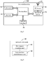
- the first wireless relay 500 includes an antenna 51, a Radio Frequency (RF) device 52, and a baseband device 53.
- the antenna 51 is connected to the radio frequency device 52.
- the radio frequency device 52 is used to receive information via the antenna 51, and transmit the received information to the baseband device 53 for processing.
- the baseband device 53 is used to process to-be-transmitted information, and transmit the processed information to the radio frequency device 52.
- the radio frequency device 52 is used to process the received information and transmit the processed information via the antenna 51.
- a frequency band processing unit may be located within the baseband device 53, so that the above methods for the first wireless relay may be implemented within the baseband device 53.
- the baseband device 53 may include a processor 54 and a memory 55.
- the baseband device 53 may, e.g., include at least one baseband board on which a plurality of chips is located, as shown in Fig.5 .
- One chip may be, e.g., the processor 54 connected to the memory 55 and used to call a program stored in the memory 55 so as to perform operations for the first wireless relay in the above-mentioned method embodiments.
- the baseband device 53 may further include a network interface 56 used to exchange information with the radio frequency device 52.
- the network interface may be, e.g., a common public radio interface (Common Public Radio Interface, CPRI).
- the processor may include merely one processor, or a plurality of processing elements.
- the processor may be a Central Processing Unit (CPU), an Application-Specific Integrated Circuit (ASIC), or one or more Integrated Circuits (ICs) configured to implement the above-mentioned methods for the first wireless relay, e.g., one or more Digital Signal Processors (DSPs), or one or more Field Programmable Gate Arrays (FPGAs).
- the memory may include merely one memory, or a plurality of storage elements.
- the memory 55 may be a volatile memory, a nonvolatile memory or both.
- the nonvolatile memory may be a read-only memory (Read-Only Memory, ROM), a programmable ROM (Programmable ROM, PROM), an erasable PROM (Erasable PROM, EPROM), an electrically EPROM (Electrically EPROM, EEPROM) or a flash memory.
- the volatile memory may be a random access memory (Random Access Memory, RAM) which serves as an external high-speed cache.
- the RAM may be in various forms, e.g., static RAM (Static RAM, SRAM), dynamic RAM (Dynamic RAM, DRAM), synchronous DRAM (Synchronous DRAM, SDRAM), double data rate SDRAM (Double Data Rate SDRAM, DDRSDRAM), enhanced SDRAM (Enhanced SDRAM, ESDRAM), synchronous link DRAM (Synchronous Link DRAM, SLDRAM) or direct Rambus RAM (Direct Rambus RAM, DRRAM).
- the memory 55 intends to include, but not limited to, the above-mentioned and any other appropriate memories.
- the first wireless relay may further include a computer program stored in the memory 55 and executed by the processor 54.
- the processor 54 is used to call the computer program stored in the memory 55, so as to implement the method executed by the modules in Fig.4 .
- the processor 54 is further used to call the computer program so as to: establish a neighbor list for the first wireless relay, the neighbor list including at least one neighbor relay of the first wireless relay, the neighbor relay being a wireless relay whose signal quality detected by the first wireless relay meets a predetermined condition; and establish an interface between the first wireless relay and the neighbor relay.
- the processor 54 is further used to call the computer program so as to establish an interface between the first wireless relay and the network side node, or establish an interface between the first wireless relay and a second wireless relay in a backhaul network.
- the processor 54 is further used to call the computer program so as to: transmit a first connection request message to the network side node when a signal from the network side node has been detected, receive a first connection establishment message transmitted from the network side node, and establish the interface between the first wireless relay and the network side node, the first connection request message carrying identification information for authenticating a relay identity of the first wireless relay; or receive a second connection establishment message that is transmitted from the network side node and forwarded by a third wireless relay, and establish the interface between the first wireless relay and the network side node.
- the processor 54 is further used to call the computer program so as to transmit a second connection request message to the third wireless relay when a signal from the third wireless relay has been detected, and the second connection request message may carry the identification information for authenticating the relay identity of the first wireless relay.
- the processor 54 is further used to call the computer program so as to receive a third connection establishment message transmitted from the second wireless relay, and establish an interface between the first wireless relay and the second wireless relay.
- the processor 54 is further used to call the computer program so as to: detect information about signal quality of each wireless relay neighboring to the first wireless relay through detecting a wireless signal; and transmit the information about the signal quality of the detected wireless relay to the network side node, and receive the neighbor list for the first wireless relay returned from the network side node, or select wireless relays whose signal quality meets the predetermined condition from the detected wireless relays to acquire the neighbor list for the first wireless relay.
- a first wireless relay which includes a processor, a memory, and a computer program stored in the memory and executed by a processor.
- the processor is used to execute the computer program so as to implement the above-mentioned neighboring relationship establishment method.
- the present disclosure further provides in an embodiment a network side node 60, which includes: a first request reception unit 61 used to receive a first connection request message transmitted from a first wireless relay, the first connection request message carrying identification information for authenticating a relay identity of the first wireless relay; and a first interface establishment unit 62 used to, after the relay identity of the first wireless relay has been authenticated successfully, transmit a first connection establishment message to the first wireless relay, and establish an interface between the network side node and the first wireless relay.
- a network side node 60 which includes: a first request reception unit 61 used to receive a first connection request message transmitted from a first wireless relay, the first connection request message carrying identification information for authenticating a relay identity of the first wireless relay; and a first interface establishment unit 62 used to, after the relay identity of the first wireless relay has been authenticated successfully, transmit a first connection establishment message to the first wireless relay, and establish an interface between the network side node and the first wireless relay.
- the network side node may further include: a second request reception unit used to receive a second connection request message forwarded by the first wireless relay, the second connection request message carrying identification information for authenticating a relay identity of a second wireless relay; and a second interface establishment unit used to, after the relay identity of the second wireless relay has been authenticated successfully, transmit a second connection establishment message to the second wireless relay through the first wireless relay, and establish an interface between the network side node and the second wireless relay, or indicate the first wireless relay to establish an interface between the first wireless relay and the second wireless relay.
- a second request reception unit used to receive a second connection request message forwarded by the first wireless relay, the second connection request message carrying identification information for authenticating a relay identity of a second wireless relay
- a second interface establishment unit used to, after the relay identity of the second wireless relay has been authenticated successfully, transmit a second connection establishment message to the second wireless relay through the first wireless relay, and establish an interface between the network side node and the second wireless relay, or indicate the first wireless relay to establish an interface between the first wireless
- the network side node may further include a neighbor list acquisition unit used to: receive from the first wireless relay a neighbor list for the first wireless relay; or receive information about signal quality of wireless relays detected by the first wireless relay, select wireless relays whose signal quality meets a predetermined condition from the wireless relays detected by the first wireless relay to acquire the neighbor list for the first wireless relay, and then transmit the neighbor list to the first wireless relay.
- a neighbor list acquisition unit used to: receive from the first wireless relay a neighbor list for the first wireless relay; or receive information about signal quality of wireless relays detected by the first wireless relay, select wireless relays whose signal quality meets a predetermined condition from the wireless relays detected by the first wireless relay to acquire the neighbor list for the first wireless relay, and then transmit the neighbor list to the first wireless relay.
- the network side node may further include a neighbor list maintenance unit used to establish and maintain at least one path from the network side node to each wireless relay in accordance with the neighbor list of the wireless relays.
- a neighbor list maintenance unit used to establish and maintain at least one path from the network side node to each wireless relay in accordance with the neighbor list of the wireless relays.
- the present disclosure further provides in an embodiment a network side node.
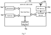
- the network side node 700 includes an antenna 71, a radio frequency device 72, and a baseband device 73.
- the antenna 71 is connected to the radio frequency device 72.
- the radio frequency device 72 is used to receive information via the antenna 71, and transmit the received information to the baseband device 73 for processing.
- the baseband device 73 is used to process to-be-transmitted information, and transmit the processed information to the radio frequency device 72.
- the radio frequency device 72 is used to process the received information and transmit the processed information via the antenna 71.
- the frequency band processing device may be located within the baseband device 73, so that the above method for the network side node may be implemented within the baseband device 73.
- the baseband device 73 may include a processor 74 and a memory 75.
- the baseband device 73 may, e.g., include at least one baseband board on which a plurality of chips is located, as shown in Fig.7 .
- One chip may be, e.g., the processor 74 connected to the memory 75 and used to call a program stored in the memory 75 so as to perform operations for the network side node in the above-mentioned method embodiments.
- the baseband device 73 may further include a network interface 76 used to exchange information with the radio frequency device 72.
- the network interface may be, e.g., a common public radio interface (Common Public Radio Interface, CPRI).
- the processor may include merely one processor, or a plurality of processing elements.
- the processor may be a CPU, an ASIC, or one or more ICs configured to implement the above-mentioned methods for the network side node, e.g., one or more DSPs, or one or more FPGAs.
- the memory may include merely one memory, or a plurality of storage elements.
- the memory 75 may be a volatile memory, a nonvolatile memory or both.
- the nonvolatile memory may be a read-only memory (Read-Only Memory, ROM), a programmable ROM (Programmable ROM, PROM), an erasable PROM (Erasable PROM, EPROM), an electrically EPROM (Electrically EPROM, EEPROM) or a flash memory.
- the volatile memory may be a random access memory (Random Access Memory, RAM) which serves as an external high-speed cache.
- the RAM may be in various forms, e.g., static RAM (Static RAM, SRAM), dynamic RAM (Dynamic RAM, DRAM), synchronous DRAM (Synchronous DRAM, SDRAM), double data rate SDRAM (Double Data Rate SDRAM, DDRSDRAM), enhanced SDRAM (Enhanced SDRAM, ESDRAM), synchronous link DRAM (Synchronous Link DRAM, SLDRAM) or direct Rambus RAM (Direct Rambus RAM, DRRAM).
- the memory 75 intends to include, but not limited to, the above-mentioned and any other appropriate memories.
- the network side node may further include a computer program stored in the memory 75 and executed by the processor 74.
- the processor 74 is used to call the computer program stored in the memory 75, so as to implement the method executed by the modules in Fig.6 .
- the processor 74 is further used to call the computer program, so as to: receive a first connection request message transmitted from a first wireless relay, the first connection request message carrying identification information for authenticating a relay identity of the first wireless relay; and after the relay identity of the first wireless relay has been authenticated successfully, transmit a first connection establishment message to the first wireless relay, and establish an interface between the network side node and the first wireless relay.
- the processor 74 is further used to call the computer program, so as to: receive a second connection request message forwarded by the first wireless relay, the second connection request message carrying identification information for authenticating a relay identity of a second wireless relay; and after the relay identity of the second wireless relay has been authenticated successfully, transmit a second connection establishment message to the second wireless relay through the first wireless relay, and establish an interface between the network side node and the second wireless relay, or indicate the first wireless relay to establish an interface between the first wireless relay and the second wireless relay.
- the processor 74 is further used to call the computer program, so as to: receive from the first wireless relay a neighbor list for the first wireless relay; or receive information about signal quality of wireless relays detected by the first wireless relay, select wireless relays whose signal quality meets a predetermined condition from the wireless relays detected by the first wireless relay to acquire the neighbor list for the first wireless relay, and then transmit the neighbor list to the first wireless relay.
- the processor 74 is further used to call the computer program, so as to establish and maintain at least one path from the network side node to each wireless relay in accordance with the neighbor list of the wireless relays.
- the present disclosure further provides in an embodiment a network side node, which includes a processor, a memory, and a computer program stored in the memory and executed by a processor.
- the processor is used to execute the computer program so as to implement the above-mentioned neighboring relationship establishment method.
- the present disclosure further provides in an embodiment a computer-readable storage medium storing therein a computer program.
- the computer program is executed by a processor so as to implement the above-mentioned neighboring relationship establishment methods.
- the computer-readable storage medium may be a read-only memory (Read-Only Memory, ROM), a random access memory (Random Access Memory, RAM), a magnetic disk or an optical disk.
- the above modules of the network device and the terminal are divided merely on the basis of their logic functions, and in actual use, they may be completely or partially integrated into a physical entity, or physically separated from each other. And these modules can all be implemented in the form of software called by processing elements; or they can also be all implemented in the form of hardware; or some modules can be implemented in the form of calling software by processing elements, and some of the modules are implemented in the form of hardware.
- the determination module may be a processing element arranged separately, or integrated into a chip of the above-mentioned device.
- the determination module may be stored in the memory of the above-mentioned device in the form of program codes, and the function of the determination module may be called and executed by a processing element of the above-mentioned device so as to achieve the above functions.
- the other modules may be implemented in a similar manner. All or parts of the modules may be integrated together or arranged separately.
- the processing element may be an IC having a signal processing capability.
- the steps of the method or the modules may be implemented through an integrated logic circuit of the processing element in the form of hardware or through instructions in the form of software.
- the above modules may be one or more ICs capable of implementing the above-mentioned method, e.g., one or more application specific integrated circuits (Application Specific Integrated Circuits, ASICs), one or more digital signal processors (Digital Signal Processors, DSPs), or one or more field programmable gate arrays (Field Programmable Gate Arrays, FPGAs).
- ASICs Application Specific Integrated Circuits
- DSPs Digital Signal Processors
- FPGAs Field Programmable Gate Arrays
- the processing element may be a general-purpose processor, e.g., a central processing unit (Central Processing Unit, CPU) or another processor capable of calling the program code.
- CPU Central Processing Unit
- These modules may be integrated together and implemented in the form of system-on-a-chip (System-On-a-Chip, SOC).
- the disclosed device and method may be implemented in other ways.
- the device embodiments described above are only schematic.
- the division of the unit is only a logical function division, and there may be other divisions in actual implementation, for example, multiple units or components may be combined or can be integrated into another system, or some features can be ignored, or not implemented.
- the displayed or discussed mutual coupling or direct coupling or communication connection may be indirect coupling or communication connection through some interfaces, devices or units, and may be in electrical, mechanical, or other forms.
- the units may be, or may not be, physically separated from each other.
- the components displayed as units may or may not be physical units, that is, they may be located in one place, or may be distributed on multiple network units. Some or all of the units may be selected according to actual needs to achieve the purpose of the solution of this embodiment.
- the functional units in the various embodiments of the present disclosure may be integrated into one processing unit, or each unit may exist alone physically, or two or more units may be integrated into one unit.
- the functional units are implemented in a software form and sold or used as a separate product, they may be stored in a computer-readable medium.
- the technical solution of the present disclosure essentially or part of the contribution to the prior art or part of the technical solution can be embodied in the form of a software product, and the computer software product is stored in a storage medium and include several instructions so as to enable computer equipment (a personal computer, a server or network equipment) to execute all or parts of the steps of the method according to the embodiments of the present disclosure.
- the storage medium includes any medium capable of storing therein program codes, e.g., a Universal Serial Bus (USB) flash disk, a mobile Hard Disk (HD), an ROM, an RAM, a magnetic disk or an optical disk.
- the members and/or steps may be subdivided and/or recombined, which shall also be deemed as equivalents of the present disclosure.
- the steps for executing the above-mentioned processings may naturally be performed in a time sequence according to the order of description, but do not necessarily need to be performed in a time sequence, and some steps can be performed in parallel or independently of each other.
- the purpose of the present disclosure can also be realized by running a program or a group of programs on any computing device.
- the computing device may be a well-known general-purpose device. Therefore, the purpose of the present disclosure can also be achieved only by providing a program product including program code for implementing the method or device. That is, such a program product also constitutes the present disclosure, and a storage medium storing such a program product also constitutes the present disclosure.
- the storage medium may be any well-known storage medium or any storage medium developed in the future. It should also be pointed out that, in the device and method of the present disclosure, obviously, each component or each step can be decomposed and/or recombined.
Landscapes
- Engineering & Computer Science (AREA)
- Computer Networks & Wireless Communication (AREA)
- Signal Processing (AREA)
- Computer Security & Cryptography (AREA)
- Mobile Radio Communication Systems (AREA)
- Radio Relay Systems (AREA)
Abstract
Description
- The present application claims a priority of the Chinese patent application No.
201810152162.5 - The present disclosure relates to the field of communications technologies, in particular to a neighboring relationship establishment method, a wireless relay and a network side node.
- In a 5th-Generation (5G) mobile communications system, the use of a wireless relay as a node device of a backhaul network is currently being studied. A wireless relay backhaul technology includes the use of a wireless backhaul link at a high frequency band of more than 6GHz. For the wireless relay (Relay) backhaul technology, one or more wireless relay nodes is added between a network side node and a terminal, so as to relay a wireless signal for one or more times, i.e., usually the wireless signal can reach the terminal in a multi-hop manner.
- Taking a simple two-hop relay as an example, usually a link from the network side node to the terminal is divided into two links, i.e., a link from the network side node to a relay and a link from the relay to the terminal, and this gives an opportunity to replace a link with inferior quality with two links each with superior quality, so as to acquire a higher link capacity and a better coverage.
- Currently, there is no definite scheme about how to establish and maintain a neighboring relationship between nodes in the backhaul network.
- An object of the present disclosure is to provide a neighboring relationship establishment method, a wireless relay and a network side node, so as to rapidly recover data transmission when a backhaul path is interrupted.
- In a first aspect, the present disclosure provides in an embodiment a neighboring relationship establishment method for a first wireless relay, including: establishing a neighbor list for the first wireless relay, the neighbor list including at least one neighbor relay of the first wireless relay, the neighbor relay being a wireless relay whose signal quality detected by the first wireless relay meets a predetermined condition; and establishing an interface between the first wireless relay and the neighbor relay.
- In a second aspect, the present disclosure provides in an embodiment a neighboring relationship establishment method for a network side node, including: receiving, by the network side node, a first connection request message transmitted from a first wireless relay, the first connection request message carrying identification information for authenticating a relay identity of the first wireless relay; and after the relay identity of the first wireless relay has been authenticated successfully, transmitting a first connection establishment message to the first wireless relay, to establish an interface between the network side node and the first wireless relay.
- In a third aspect, the present disclosure provides in an embodiment a first wireless relay, including: a neighboring relationship establishment unit used to establish a neighbor list for the first wireless relay, the neighbor list including at least one neighbor relay of the first wireless relay, the neighbor relay being a wireless relay whose signal quality detected by the first wireless relay meets a predetermined condition; and a neighboring interface establishment unit used to establish an interface between the first wireless relay and the neighbor relay.
- In a fourth aspect, the present disclosure provides in an embodiment a first wireless relay, including a processor, a memory, and a computer program stored in the memory and capable of being executed by the processor. The processor is used to execute the computer program so as to implement steps of the above-mentioned neighboring relationship establishment method.
- In a fifth aspect, the present disclosure provides in an embodiment a network side node, including: a first request reception unit used to receive a first connection request message transmitted from a first wireless relay, the first connection request message carrying identification information for authenticating a relay identity of the first wireless relay; and a first interface establishment unit used to, after the relay identity of the first wireless relay has been authenticated successfully, transmit a first connection establishment message to the first wireless relay, to establish an interface between the network side node and the first wireless relay.
- In a sixth aspect, the present disclosure provides in an embodiment a network side node, including a processor, a memory, and a computer program stored in the memory and capable of being executed by the processor. The processor is used to execute the computer program to implement steps of the above-mentioned neighboring relationship establishment method.
- In a seventh aspect, the present disclosure provides in an embodiment a computer-readable storage medium storing therein a computer program. The computer program is executed by a processor to implement steps of the above-mentioned neighboring relationship establishment method.
- According to the neighboring relationship establishment method, the wireless relay and the network side node in the embodiments of the present disclosure, through establishing the neighbor list for the first wireless relay and establishing the interface between the first wireless relay and the neighbor relay, it is able to establish and maintain the neighboring relationship between the wireless relays.
- In order to illustrate the technical solutions of the present disclosure in a clearer manner, the drawings desired for the present disclosure will be described hereinafter briefly. Obviously, the following drawings merely relate to some embodiments of the present disclosure, and based on these drawings, a person skilled in the art may obtain the other drawings without any creative effort.
-
Fig.1 is a schematic diagram showing an application scenario according to an embodiment of the present disclosure; -
Fig.2 is a flow chart of a neighboring relationship establishment method according to an embodiment of the present disclosure; -
Fig.3 is another flow chart of the neighboring relationship establishment method according to an embodiment of the present disclosure; -
Fig.4 is a schematic diagram showing a first wireless relay according to an embodiment of the present disclosure; -
Fig.5 is a block diagram of the first wireless relay according to an embodiment of the present disclosure; -
Fig.6 is a schematic diagram showing a network side node according to an embodiment of the present disclosure; and -
Fig.7 is a block diagram of the network side node according to an embodiment of the present disclosure. - Hereinafter, exemplary embodiments of the present disclosure will be described in more detail with reference to the drawings. Although the exemplary embodiments of the present disclosure are shown in the drawings, it should be understood that the present disclosure can be implemented in various forms and should not be limited by the embodiments set forth herein. Rather, these embodiments are provided to enable a more thorough understanding of the present disclosure and to fully convey the scope of the present disclosure to a person skilled in the art.
- Such words as "first" and "second" involved in the specification and the appended claims are merely used to differentiate similar objects, and do not have to be used to describe a specific order or sequence. It should be understood that the data used in this way are interchangeable under appropriate circumstances so that the embodiments of the present application described herein can be implemented in an order other than those illustrated or described herein, for example. In addition, the terms "including" and "having" and any variations thereof are intended to cover non-exclusive inclusions, for example, processes, methods, systems, products or devices that contain a series of steps or units need not be limited to those clearly listed Those steps or units may include other steps or units that are not clearly listed or are inherent to these processes, methods, products, or devices.
- In the embodiments of the present disclosure, the form of a network side node will not be particularly defined, and it may be a macro base station (Macro Base Station), a pico base station (Pico Base Station), a Node B (3rd-Generation (3G) base station), an evolved Node B (eNB), a Femto eNB (or Home eNode B or Home eNB or HeNB), a relay, an access point, a remote radio unit (Remote Radio Unit, RRU), a remote radio head (Remote Radio Head, RRH), or a network side node in a 5G mobile communications system, e.g., a central unit (Central Unit, CU) or a distributed unit (Distributed Unit, DU) of a base station (gNB). A terminal in the embodiments of the present disclosure may be a mobile phone (or cellular phone) or another device capable of transmitting or receiving a radio signal, including a User Equipment (UE), a Personal Digital Assistant (PDA), a wireless modem, a wireless communication device, a handheld device, a laptop computer, a cordless telephone, a Wireless Local Loop (WLL) station, a customer premise equipment (Customer Premise Equipment, CPE) capable of converting a mobile communication signal into a WiFi signal, a mobile smart hotspot, smart appliance, or another device capable of spontaneously communicating with a mobile communication network without manual operation.
-
Fig. 1 shows an example of a multi-hop wireless relay backhaul path. As shown inFig.1 , a wireless backhaul network consists ofwireless relays 1 to 7. In the embodiments of the present disclosure, usually the wireless backhaul network includes a plurality of wireless relays, parts of which may directly communicate with a network side node, and parts of which may communicate with the network side node via the other wireless relays. Based on these wireless relays, it is able to establish a backhaul path from the network side node to a terminal. InFig.1 , the multi-hop backhaul path from the network side node (e.g., a donor base station, specifically a donor gNB) to the terminal through awireless relay 2, awireless relay 4 and awireless relay 5 sequentially in that order. Taking a 5G system as an example, each wireless relay inFig.1 may be called as integrated access and backhaul (Integrated Access and Backhaul, IAB). The IAB may have a complete base station function, or merely have a data forwarding function similar to the base station. The network side node with wired interface connection is just the base station, which may also be called as donor Integrated Access and Backhaul (DIAB). The IAB may communicate with the DIAB via a wireless interface. Naturally, the IABs may also communicate with each other via a wireless interface. In the embodiments of the present disclosure, an IAB to which the terminal accesses and which is directly used to provide services to the terminal (UE) may be called as a serving IAB (Serving IAB, SIAB). In the above backhaul path, a prior-hop IAB of the SIAB may be called as NIAB (Next IAB). - In the 5G system, the use of a wireless relay as a node device of a backhaul network is currently being studied, so as to create the backhaul network. Currently, there is no definite scheme about how to establish and maintain a neighboring relationship between the wireless relays. To solve this problem, the present disclosure provides in an embodiment a neighboring relationship establishment method for a first wireless relay in a backhaul network which, as shown in
Fig.2 , includes the following steps. - Step 21: establishing a neighbor list for the first wireless relay, the neighbor list including at least one neighbor relay of the first wireless relay, the neighbor relay being a wireless relay whose signal quality detected by the first wireless relay meets a predetermined condition.
- Here, the neighbor list may be generated by the first wireless relay in accordance with the detected signal quality of the neighboring wireless relays, i.e., the wireless relays whose signal quality meets the predetermined condition may be selected from the detected wireless relays to generate the neighbor list for the first wireless relay. In this case, the predetermined condition may be pre-configured at the first wireless relay. As a specific configuration mode, the predetermined condition may be pre-configured manually, or configuration information including the predetermined condition may be received by the first wireless relay from the network side node and then the predetermined condition may be configured locally at the first wireless relay. Further, subsequent to the generation of the neighbor list for the first wireless relay, the first wireless relay may transmit the neighbor list to the network side node.
- As another implementation mode, the neighbor list may be acquired from the network side node. For example, the first wireless relay may transmit information about the detected signal quality of the neighboring wireless relays to the network side node. To be specific, the first wireless relay may transmit the information about the detected signal quality about all the wireless relays to the network side node, or merely transmit the information about the signal quality of parts of the wireless relays, e.g., the information about the signal quality of the wireless relays which meets the predetermined condition or another condition, to the network side node. Then, the network side node may generate the neighbor list for the first wireless relay in accordance with the information about the signal quality transmitted from the first wireless relay. The first wireless relay may receive the neighbor list for the first wireless relay transmitted from the network side node, so as to acquire the neighbor list.
- Step 22: establishing an interface between the first wireless relay and the neighbor relay.
- As mentioned above, through establishing the neighbor list for the first wireless relay and establishing the interface between the first wireless relay and the neighbor relay, it is able to maintain the neighboring relationship of the first wireless relay. Here, in the embodiments of the present disclosure, the wireless relay whose signal quality detected by the first wireless relay meets the predetermined condition may serve as the neighbor relay, so it is able to ensure the relatively reliable signal quality between the relays neighboring to each other, thereby to improve the reliability of the data transmission therebetween.
- In the embodiments of the present disclosure, as an implementation mode, reference signal receiving power (Reference Signal Receiving Power, RSRP) may be used as a reference for the signal quality. For example, when the RSRP of a certain wireless relay detected by the first wireless relay is greater than a predetermined reference threshold, the wireless relay may be selected as the neighbor relay. Naturally, in the embodiments of the present disclosure, another index for the signal quality, e.g., received signal strength indication (Received Signal Strength Indication, RSSI), signal to interference ratio (Signal to Interference Ratio, SIR) and signal to interference plus noise ratio (Signal to Interference plus Noise Ratio, SINR), may also be used.
- In the embodiments of the present disclosure, prior to establishing the neighbor list for the first wireless relay, the first wireless relay may join the backhaul network through establishing the interface between the first wireless relay and the network side node. For example, when the first wireless relay is starting up or initially deployed, it may receive system information transmitted from the network side node (the system information may include identification information indicating that a current node is the network side node or a relay node), so as to identify the network side node, and establish the interface between the first wireless relay and the network side node.
- The establishment of the interface between the first wireless relay and the network side node will be described hereinafter.
- In the embodiments of the present disclosure, the first wireless relay may transmit a first connection request message to the network side node when a signal from the network side node has been detected by the first wireless relay. The first connection request message may carry identification information for authenticating a relay identity of the first wireless relay, and the first connection request message may further carry one or more of a cell Identity (ID), a Physical Cell Identifier (PCI), a frequency and a beam index. Then, the network side node may transmit the first connection request message to a network element managing the wireless relay access, e.g., an access and mobility management (Access and Mobility Management, AMF) network element, for authentication. After the relay identity has been authenticated successfully, the network element may return information indicating that a connection request from the first wireless relay is accepted to the network side node. At this time, the network side node may transmit a first connection establishment message to the first wireless relay. The first wireless relay may receive the first connection establishment message transmitted from the network side node, and establish the interface between the first wireless relay and the network side node.
- As another establishment mode, upon the receipt of a second connection establishment message forwarded by a third wireless relay, the first wireless relay may establish the interface between the first wireless relay and the network side node. Here, the third wireless relay may be a relay that has already joined the backhaul network. The second connection establishment message may be forwarded by the network side node through the third wireless relay. In this establishment mode, the interface may be established in accordance with the message forwarded by the third wireless relay between the network side node and the first wireless relay. In addition, prior to receiving the second connection establishment message, the first wireless relay may transmit a second connection request message to the third wireless relay when a signal from the third wireless relay has been detected by the first wireless relay, and the second connection request message may carry identification information for authenticating the relay identity of the first wireless relay. Similarly, the second connection request message may be forwarded to the network element managing the wireless relay access for authentication, which will not be particularly defined herein.
- Apart from the establishment of the interface between the first wireless relay and the network side node to join the backhaul network, in the embodiments of the present disclosure, the first wireless relay may also join the backhaul network through establishing an interface between the first wireless relay and a second wireless relay that has already joined the backhaul network. For example, the first wireless relay may transmit a third connection request message to the second wireless relay when a signal from the second wireless relay has been detected, and the third connection request message may carry the identification information for authenticating the relay identity of the first wireless relay. The second wireless relay may forward the third connection request message to the network element managing the wireless relay access for authentication, which will not be particularly defined herein. After the relay identity has been successfully authenticated, the second wireless relay may transmit a third connection establishment message to the first wireless relay. At this time, the first wireless relay may receive the third connection establishment message, and establish the interface between the first wireless relay and the second wireless relay.
- As can be seen from the above, in the embodiments of the present disclosure, in order to enable a new wireless relay to join the backhaul network, an interface between the new wireless relay and the network side node may be established directly, or an interface between the new wireless relay and another wireless relay that has already joined the backhaul network may be established.
- In the embodiments of the present disclosure, the interface between the wireless relays and the interface between the wireless relay and the network side node may each be a Uu, X2, Xn, F1 or E1 interface, or another interface.
- Through the above steps, it is able for the wireless relay to join the backhaul network, and it enables to establish and maintain the neighboring relationship between the wireless relays.
- The establishment of the neighboring relationship will be described hereinafter from the aspect of the perspective of the network side node.
- As shown in
Fig.3 , the present disclosure further provides in an embodiment a neighboring relationship establishment method for a network side node, which includes: Step 31 of receiving, by the network side node, a connection request message transmitted from a first wireless relay, the connection request message carrying identification information for authenticating a relay identity of the first wireless relay; andStep 32 of, after the relay identity of the first wireless relay has been authenticated successfully, transmitting a connection establishment message to the first wireless relay, to establish an interface between the network side node and the first wireless relay. - Here, the network side node may transmit a first connection request message to a network element managing the wireless relay access, e.g., an AMF network element, for authentication. After the relay identity has been authenticated successfully, the network element may return information indicating that a connection request from the first wireless relay is accepted to the network side node. At this time, the network side node may transmit the connection establishment message to the first wireless relay, so as to establish the interface between the first wireless relay and the network side node.
- Through the above steps, in the embodiments of the present disclosure, it is able to establish the interface between the network side node and the first wireless relay.
- Subsequent to establishing the interface between the network side node and the first wireless relay, the network side node in the embodiments of the present disclosure may further receive a second connection request message forwarded by the first wireless relay, and the second connection request message may carry identification information for authenticating a relay identity of the second wireless relay. Then, the network side node may transmit the second connection request message to the network element managing the wireless relay access, e.g., the AMF network element, for authentication. After the relay identity has been authenticated successfully, the network element may return information indicating that a connection request from the second wireless relay is accepted to the network side node. At this time, the network side node may transmit a second connection establishment message to the second wireless relay via the first wireless relay to establish an interface between the network side node and the second wireless relay, or transmit an indication to the first wireless relay to indicate the establishment of an interface between the first wireless relay and the second wireless relay.
- Further, subsequent to establishing the interface between the network side node and the first wireless relay, the network side node in the embodiments of the present disclosure may further receive from the first wireless relay a neighbor list for the first wireless relay. At this time, the neighbor list may be generated by the first wireless relay itself. Alternatively, the network side node may further receive information about signal quality of wireless relays detected by the first wireless relay, select wireless relays whose signal quality meets a predetermined condition from the detected wireless relays to acquire the neighbor list for the first wireless relay, and then transmit the neighbor list to the first wireless relay.
- Through the above modes, the network side node in the embodiments of the present disclosure may acquire the neighbor list of the wireless relays in the backhaul network, so as to establish and maintain at least one path from the network side node to each wireless relay.
- According to the embodiments of the present disclosure, it is able to establish the backhaul network including the wireless relays, and establish and maintain the neighboring relationship between the relay nodes.
- The neighboring relationship establishment methods in different scenarios have been described in detail hereinabove, and corresponding devices will be described hereinafter in conjunction with the drawings.
- As shown in
Fig.4 , the present disclosure provides in an embodiment afirst wireless relay 40, which includes: a neighboringrelationship establishment unit 41 used to establish a neighbor list for the first wireless relay, the neighbor list including at least one neighbor relay of the first wireless relay, the neighbor relay being a wireless relay whose signal quality detected by the first wireless relay meets a predetermined condition; and a neighboringinterface establishment unit 42 used to establish an interface between the first wireless relay and the neighbor relay. - Preferably, the first wireless relay may further include a network joining unit used to establish an interface between the first wireless relay and the network side node to enable the first wireless relay to join a backhaul network, or establish an interface between the first wireless relay and a second wireless relay in the backhaul network to enable the first wireless relay to join the backhaul network.
- Preferably, the network joining unit may include: a first joining unit used to transmit a first connection request message to the network side node when a signal from the network side node has been detected by the first joining unit, receive a first connection establishment message transmitted from the network side node, to establish the interface between the first wireless relay and the network side node, the first connection request message carrying identification information for authenticating a relay identity of the first wireless relay; or a second joining unit used to receive a second connection establishment message that is transmitted from the network side node and forwarded by a third wireless relay, to establish the interface between the first wireless relay and the network side node.
- Preferably, the second joining unit is further used to, prior to receiving a second connection establishment message, transmit a second connection request message to the third wireless relay when a signal from the third wireless relay has been detected by the second joining unit, and the second connection request message may carry the identification information for authenticating the relay identity of the first wireless relay.
- Preferably, the network joining unit is further used to receive a third connection establishment message transmitted from the second wireless relay, to establish an interface between the first wireless relay and the second wireless relay.
- Preferably, the neighboring relationship establishment unit is further used to: detect information about signal quality of each wireless relay neighboring to the first wireless relay through detecting a wireless signal; and transmit the information about the signal quality of the detected wireless relay to the network side node, and receive the neighbor list for the first wireless relay from the network side node, or select wireless relays whose signal quality meets the predetermined condition from the detected wireless relays to acquire the neighbor list for the first wireless relay.
- The present disclosure further provides in an embodiment another first wireless relay. As shown in
Fig.5 , thefirst wireless relay 500 includes anantenna 51, a Radio Frequency (RF)device 52, and abaseband device 53. Theantenna 51 is connected to theradio frequency device 52. In an uplink direction, theradio frequency device 52 is used to receive information via theantenna 51, and transmit the received information to thebaseband device 53 for processing. In a downlink direction, thebaseband device 53 is used to process to-be-transmitted information, and transmit the processed information to theradio frequency device 52. Theradio frequency device 52 is used to process the received information and transmit the processed information via theantenna 51. - A frequency band processing unit may be located within the
baseband device 53, so that the above methods for the first wireless relay may be implemented within thebaseband device 53. Thebaseband device 53 may include aprocessor 54 and amemory 55. - The
baseband device 53 may, e.g., include at least one baseband board on which a plurality of chips is located, as shown inFig.5 . One chip may be, e.g., theprocessor 54 connected to thememory 55 and used to call a program stored in thememory 55 so as to perform operations for the first wireless relay in the above-mentioned method embodiments. - The
baseband device 53 may further include anetwork interface 56 used to exchange information with theradio frequency device 52. The network interface may be, e.g., a common public radio interface (Common Public Radio Interface, CPRI). - Here, the processor may include merely one processor, or a plurality of processing elements. For example, the processor may be a Central Processing Unit (CPU), an Application-Specific Integrated Circuit (ASIC), or one or more Integrated Circuits (ICs) configured to implement the above-mentioned methods for the first wireless relay, e.g., one or more Digital Signal Processors (DSPs), or one or more Field Programmable Gate Arrays (FPGAs). The memory may include merely one memory, or a plurality of storage elements.
- The
memory 55 may be a volatile memory, a nonvolatile memory or both. The nonvolatile memory may be a read-only memory (Read-Only Memory, ROM), a programmable ROM (Programmable ROM, PROM), an erasable PROM (Erasable PROM, EPROM), an electrically EPROM (Electrically EPROM, EEPROM) or a flash memory. The volatile memory may be a random access memory (Random Access Memory, RAM) which serves as an external high-speed cache. Illustratively but nonrestrictively, the RAM may be in various forms, e.g., static RAM (Static RAM, SRAM), dynamic RAM (Dynamic RAM, DRAM), synchronous DRAM (Synchronous DRAM, SDRAM), double data rate SDRAM (Double Data Rate SDRAM, DDRSDRAM), enhanced SDRAM (Enhanced SDRAM, ESDRAM), synchronous link DRAM (Synchronous Link DRAM, SLDRAM) or direct Rambus RAM (Direct Rambus RAM, DRRAM). Thememory 55 intends to include, but not limited to, the above-mentioned and any other appropriate memories. - To be specific, in the embodiments of the present disclosure, the first wireless relay may further include a computer program stored in the
memory 55 and executed by theprocessor 54. Theprocessor 54 is used to call the computer program stored in thememory 55, so as to implement the method executed by the modules inFig.4 . - To be specific, the
processor 54 is further used to call the computer program so as to: establish a neighbor list for the first wireless relay, the neighbor list including at least one neighbor relay of the first wireless relay, the neighbor relay being a wireless relay whose signal quality detected by the first wireless relay meets a predetermined condition; and establish an interface between the first wireless relay and the neighbor relay. - To be specific, the
processor 54 is further used to call the computer program so as to establish an interface between the first wireless relay and the network side node, or establish an interface between the first wireless relay and a second wireless relay in a backhaul network. - To be specific, the
processor 54 is further used to call the computer program so as to: transmit a first connection request message to the network side node when a signal from the network side node has been detected, receive a first connection establishment message transmitted from the network side node, and establish the interface between the first wireless relay and the network side node, the first connection request message carrying identification information for authenticating a relay identity of the first wireless relay; or receive a second connection establishment message that is transmitted from the network side node and forwarded by a third wireless relay, and establish the interface between the first wireless relay and the network side node. - To be specific, the
processor 54 is further used to call the computer program so as to transmit a second connection request message to the third wireless relay when a signal from the third wireless relay has been detected, and the second connection request message may carry the identification information for authenticating the relay identity of the first wireless relay. - To be specific, the
processor 54 is further used to call the computer program so as to receive a third connection establishment message transmitted from the second wireless relay, and establish an interface between the first wireless relay and the second wireless relay. - To be specific, the
processor 54 is further used to call the computer program so as to: detect information about signal quality of each wireless relay neighboring to the first wireless relay through detecting a wireless signal; and transmit the information about the signal quality of the detected wireless relay to the network side node, and receive the neighbor list for the first wireless relay returned from the network side node, or select wireless relays whose signal quality meets the predetermined condition from the detected wireless relays to acquire the neighbor list for the first wireless relay. - In order to achieve the above purpose in a better manner, the present disclosure further provides in an embodiment a first wireless relay, which includes a processor, a memory, and a computer program stored in the memory and executed by a processor. The processor is used to execute the computer program so as to implement the above-mentioned neighboring relationship establishment method.
- As shown in
Fig.6 , the present disclosure further provides in an embodiment anetwork side node 60, which includes: a firstrequest reception unit 61 used to receive a first connection request message transmitted from a first wireless relay, the first connection request message carrying identification information for authenticating a relay identity of the first wireless relay; and a firstinterface establishment unit 62 used to, after the relay identity of the first wireless relay has been authenticated successfully, transmit a first connection establishment message to the first wireless relay, and establish an interface between the network side node and the first wireless relay. - Preferably, the network side node may further include: a second request reception unit used to receive a second connection request message forwarded by the first wireless relay, the second connection request message carrying identification information for authenticating a relay identity of a second wireless relay; and a second interface establishment unit used to, after the relay identity of the second wireless relay has been authenticated successfully, transmit a second connection establishment message to the second wireless relay through the first wireless relay, and establish an interface between the network side node and the second wireless relay, or indicate the first wireless relay to establish an interface between the first wireless relay and the second wireless relay.
- Preferably, the network side node may further include a neighbor list acquisition unit used to: receive from the first wireless relay a neighbor list for the first wireless relay; or receive information about signal quality of wireless relays detected by the first wireless relay, select wireless relays whose signal quality meets a predetermined condition from the wireless relays detected by the first wireless relay to acquire the neighbor list for the first wireless relay, and then transmit the neighbor list to the first wireless relay.
- Preferably, the network side node may further include a neighbor list maintenance unit used to establish and maintain at least one path from the network side node to each wireless relay in accordance with the neighbor list of the wireless relays.
- The present disclosure further provides in an embodiment a network side node. As shown in
Fig.7 , thenetwork side node 700 includes an antenna 71, a radio frequency device 72, and a baseband device 73. The antenna 71 is connected to the radio frequency device 72. In an uplink direction, the radio frequency device 72 is used to receive information via the antenna 71, and transmit the received information to the baseband device 73 for processing. In a downlink direction, the baseband device 73 is used to process to-be-transmitted information, and transmit the processed information to the radio frequency device 72. The radio frequency device 72 is used to process the received information and transmit the processed information via the antenna 71. - The frequency band processing device may be located within the baseband device 73, so that the above method for the network side node may be implemented within the baseband device 73. The baseband device 73 may include a processor 74 and a memory 75.
- The baseband device 73 may, e.g., include at least one baseband board on which a plurality of chips is located, as shown in
Fig.7 . One chip may be, e.g., the processor 74 connected to the memory 75 and used to call a program stored in the memory 75 so as to perform operations for the network side node in the above-mentioned method embodiments. - The baseband device 73 may further include a network interface 76 used to exchange information with the radio frequency device 72. The network interface may be, e.g., a common public radio interface (Common Public Radio Interface, CPRI).
- Here, the processor may include merely one processor, or a plurality of processing elements. For example, the processor may be a CPU, an ASIC, or one or more ICs configured to implement the above-mentioned methods for the network side node, e.g., one or more DSPs, or one or more FPGAs. The memory may include merely one memory, or a plurality of storage elements.
- The memory 75 may be a volatile memory, a nonvolatile memory or both. The nonvolatile memory may be a read-only memory (Read-Only Memory, ROM), a programmable ROM (Programmable ROM, PROM), an erasable PROM (Erasable PROM, EPROM), an electrically EPROM (Electrically EPROM, EEPROM) or a flash memory. The volatile memory may be a random access memory (Random Access Memory, RAM) which serves as an external high-speed cache. Illustratively but nonrestrictively, the RAM may be in various forms, e.g., static RAM (Static RAM, SRAM), dynamic RAM (Dynamic RAM, DRAM), synchronous DRAM (Synchronous DRAM, SDRAM), double data rate SDRAM (Double Data Rate SDRAM, DDRSDRAM), enhanced SDRAM (Enhanced SDRAM, ESDRAM), synchronous link DRAM (Synchronous Link DRAM, SLDRAM) or direct Rambus RAM (Direct Rambus RAM, DRRAM). The memory 75 intends to include, but not limited to, the above-mentioned and any other appropriate memories.
- To be specific, in the embodiments of the present disclosure, the network side node may further include a computer program stored in the memory 75 and executed by the processor 74. The processor 74 is used to call the computer program stored in the memory 75, so as to implement the method executed by the modules in
Fig.6 . - To be specific, the processor 74 is further used to call the computer program, so as to: receive a first connection request message transmitted from a first wireless relay, the first connection request message carrying identification information for authenticating a relay identity of the first wireless relay; and after the relay identity of the first wireless relay has been authenticated successfully, transmit a first connection establishment message to the first wireless relay, and establish an interface between the network side node and the first wireless relay.
- The processor 74 is further used to call the computer program, so as to: receive a second connection request message forwarded by the first wireless relay, the second connection request message carrying identification information for authenticating a relay identity of a second wireless relay; and after the relay identity of the second wireless relay has been authenticated successfully, transmit a second connection establishment message to the second wireless relay through the first wireless relay, and establish an interface between the network side node and the second wireless relay, or indicate the first wireless relay to establish an interface between the first wireless relay and the second wireless relay.
- The processor 74 is further used to call the computer program, so as to: receive from the first wireless relay a neighbor list for the first wireless relay; or receive information about signal quality of wireless relays detected by the first wireless relay, select wireless relays whose signal quality meets a predetermined condition from the wireless relays detected by the first wireless relay to acquire the neighbor list for the first wireless relay, and then transmit the neighbor list to the first wireless relay.
- The processor 74 is further used to call the computer program, so as to establish and maintain at least one path from the network side node to each wireless relay in accordance with the neighbor list of the wireless relays.
- In order to achieve the above purpose in a better manner, the present disclosure further provides in an embodiment a network side node, which includes a processor, a memory, and a computer program stored in the memory and executed by a processor. The processor is used to execute the computer program so as to implement the above-mentioned neighboring relationship establishment method.
- The present disclosure further provides in an embodiment a computer-readable storage medium storing therein a computer program. The computer program is executed by a processor so as to implement the above-mentioned neighboring relationship establishment methods. The computer-readable storage medium may be a read-only memory (Read-Only Memory, ROM), a random access memory (Random Access Memory, RAM), a magnetic disk or an optical disk.
- It should be further appreciated that, the above modules of the network device and the terminal are divided merely on the basis of their logic functions, and in actual use, they may be completely or partially integrated into a physical entity, or physically separated from each other. And these modules can all be implemented in the form of software called by processing elements; or they can also be all implemented in the form of hardware; or some modules can be implemented in the form of calling software by processing elements, and some of the modules are implemented in the form of hardware. For example, the determination module may be a processing element arranged separately, or integrated into a chip of the above-mentioned device. In addition, the determination module may be stored in the memory of the above-mentioned device in the form of program codes, and the function of the determination module may be called and executed by a processing element of the above-mentioned device so as to achieve the above functions. The other modules may be implemented in a similar manner. All or parts of the modules may be integrated together or arranged separately. Here, the processing element may be an IC having a signal processing capability. During the implementation, the steps of the method or the modules may be implemented through an integrated logic circuit of the processing element in the form of hardware or through instructions in the form of software.
- For example, the above modules may be one or more ICs capable of implementing the above-mentioned method, e.g., one or more application specific integrated circuits (Application Specific Integrated Circuits, ASICs), one or more digital signal processors (Digital Signal Processors, DSPs), or one or more field programmable gate arrays (Field Programmable Gate Arrays, FPGAs). For another example, when a certain module is implemented by calling a program code through a processing element, the processing element may be a general-purpose processor, e.g., a central processing unit (Central Processing Unit, CPU) or another processor capable of calling the program code. These modules may be integrated together and implemented in the form of system-on-a-chip (System-On-a-Chip, SOC).
- It should be appreciated that, units and algorithm steps described in the embodiments of the present disclosure may be implemented in the form of electronic hardware, or a combination of a computer software and the electronic hardware. Whether these functions are performed by hardware or software depends on the specific application and design constraint conditions of the technical solution. Professionals and technicians can use different methods for each specific application to implement the described functions, but such implementation should not be considered beyond the scope of the present disclosure.
- A person skilled in the art can clearly understand that, for the convenience and conciseness of description, the specific working process of the above-described system, device, and unit can refer to the corresponding process in the foregoing method embodiments, which is not repeated herein.
- In the embodiments provided in this application, it should be understood that the disclosed device and method may be implemented in other ways. For example, the device embodiments described above are only schematic. For example, the division of the unit is only a logical function division, and there may be other divisions in actual implementation, for example, multiple units or components may be combined or can be integrated into another system, or some features can be ignored, or not implemented. In addition, the displayed or discussed mutual coupling or direct coupling or communication connection may be indirect coupling or communication connection through some interfaces, devices or units, and may be in electrical, mechanical, or other forms.
- The units may be, or may not be, physically separated from each other. The components displayed as units may or may not be physical units, that is, they may be located in one place, or may be distributed on multiple network units. Some or all of the units may be selected according to actual needs to achieve the purpose of the solution of this embodiment.
- In addition, the functional units in the various embodiments of the present disclosure may be integrated into one processing unit, or each unit may exist alone physically, or two or more units may be integrated into one unit.
- In the case that the functional units are implemented in a software form and sold or used as a separate product, they may be stored in a computer-readable medium. Based on this, the technical solution of the present disclosure essentially or part of the contribution to the prior art or part of the technical solution can be embodied in the form of a software product, and the computer software product is stored in a storage medium and include several instructions so as to enable computer equipment (a personal computer, a server or network equipment) to execute all or parts of the steps of the method according to the embodiments of the present disclosure. The storage medium includes any medium capable of storing therein program codes, e.g., a Universal Serial Bus (USB) flash disk, a mobile Hard Disk (HD), an ROM, an RAM, a magnetic disk or an optical disk.
- It should be further appreciated that, according to the device and the method in the embodiments of the present disclosure, the members and/or steps may be subdivided and/or recombined, which shall also be deemed as equivalents of the present disclosure. In addition, the steps for executing the above-mentioned processings may naturally be performed in a time sequence according to the order of description, but do not necessarily need to be performed in a time sequence, and some steps can be performed in parallel or independently of each other. It should be further appreciated that, after reading the descriptions of the present disclosure, it is able for a person skilled in the art who may understand that all or any of the steps or components of the method and device of the present disclosure, using a basic programming skill, to implement any or all steps of the method and any or all members of the device in any computing device (including a processor and a storage medium) or a network consisting of the computing devices, in the form of hardware, firmware, software or a combination thereof.
- Therefore, the purpose of the present disclosure can also be realized by running a program or a group of programs on any computing device. The computing device may be a well-known general-purpose device. Therefore, the purpose of the present disclosure can also be achieved only by providing a program product including program code for implementing the method or device. That is, such a program product also constitutes the present disclosure, and a storage medium storing such a program product also constitutes the present disclosure. Obviously, the storage medium may be any well-known storage medium or any storage medium developed in the future. It should also be pointed out that, in the device and method of the present disclosure, obviously, each component or each step can be decomposed and/or recombined. These decomposition and/or recombination should be regarded as equivalent solutions of the present disclosure. In addition, the steps of executing the above-mentioned series of processing can naturally be executed in time sequence in the order of description, but it is not necessarily executed in time sequence. Certain steps can be performed in parallel or independently of each other.
- The above are preferred embodiments of the present disclosure, and it should be noted that a person of ordinary skills in the art can make further improvements and modifications without departing from the principle of the present disclosure, and these improvements and modifications should also be considered to fall within the protection scope of the present disclosure.
Claims (15)
- A neighboring relationship establishment method for a first wireless relay, wherein the neighboring relationship establishment method comprises:establishing a neighbor list for the first wireless relay, the neighbor list comprising at least one neighbor relay of the first wireless relay, the neighbor relay being a wireless relay whose signal quality detected by the first wireless relay meets a predetermined condition;establishing an interface between the first wireless relay and the neighbor relay.
- The neighboring relationship establishment method according to claim 1, wherein prior to establishing the neighbor list for the first wireless relay, the neighboring relationship establishment method further comprises:establishing, by the first wireless relay, an interface between the first wireless relay and a network side node; orestablishing, by the first wireless relay, an interface between the first wireless relay and a second wireless relay.
- The neighboring relationship establishment method according to claim 2, wherein the establishing, by the first wireless relay, the interface between the first wireless relay and the network side node comprises:transmitting, by the first wireless relay, a first connection request message to the network side node when a signal from the network side node has been detected by the first wireless relay, and receiving, by the first wireless relay, a first connection establishment message transmitted from the network side node to establish the interface between the first wireless relay and the network side node, the first connection request message carrying identification information for authenticating a relay identity of the first wireless relay; orreceiving, by the first wireless relay, a second connection establishment message that is transmitted from the network side node and forwarded by a third wireless relay, to establish the interface between the first wireless relay and the network side node.
- The neighboring relationship establishment method according to claim 3, wherein prior to receiving the second connection establishment message, the neighboring relationship establishment method further comprises:
transmitting, by the first wireless relay, a second connection request message to the third wireless relay when a signal from the third wireless relay has been detected by the first wireless relay, and the second connection request message carrying the identification information for authenticating the relay identity of the first wireless relay. - The neighboring relationship establishment method according to claim 2, wherein the establishing, by the first wireless relay, the interface between the first wireless relay and the second wireless relay comprises:
receiving, by the first wireless relay, a third connection establishment message transmitted from the second wireless relay, to establish the interface between the first wireless relay and the second wireless relay. - The neighboring relationship establishment method according to claim 1, wherein the establishing the neighbor list for the first wireless relay comprises:detecting information about signal quality of a wireless relay around the first wireless relay through detecting a wireless signal; andtransmitting the detected information about the signal quality of the wireless relay to the network side node, and receiving the neighbor list for the first wireless relay transmitted from the network side node; or selecting a wireless relay whose signal quality meets the predetermined condition from the detected wireless relays, to acquire the neighbor list for the first wireless relay.
- A neighboring relationship establishment method for a network side node, wherein the neighboring relationship establishment method comprises:receiving, by the network side node, a first connection request message transmitted from a first wireless relay, the first connection request message carrying identification information for authenticating a relay identity of the first wireless relay;after the relay identity of the first wireless relay has been authenticated successfully, transmitting a first connection establishment message to the first wireless relay, to establish an interface between the network side node and the first wireless relay.
- The neighboring relationship establishment method according to claim 7, wherein subsequent to establishing the interface between the network side node and the first wireless relay, the neighboring relationship establishment method further comprises:receiving, by the network side node, a second connection request message forwarded by the first wireless relay, the second connection request message carrying identification information for authenticating a relay identity of a second wireless relay;after the relay identity of the second wireless relay has been authenticated successfully, transmitting a second connection establishment message to the second wireless relay through the first wireless relay, to establish an interface between the network side node and the second wireless relay; or indicating the first wireless relay to establish an interface between the first wireless relay and the second wireless relay.
- The neighboring relationship establishment method according to claim 7 or 8, wherein subsequent to establishing the interface between the network side node and the first wireless relay, the neighboring relationship establishment method further comprises:receiving a neighbor list for the first wireless relay transmitted from the first wireless relay; orreceiving information about signal quality of wireless relays detected by the first wireless relay, selecting a wireless relay whose signal quality meets a predetermined condition from the wireless relays detected by the first wireless relay to acquire the neighbor list for the first wireless relay, and transmitting the neighbor list to the first wireless relay.
- The neighboring relationship establishment method according to claim 9, further comprising:
establishing and maintaining at least one path from the network side node to each wireless relay in accordance with the neighbor list of the wireless relays. - A first wireless relay, comprising:a neighboring relationship establishment unit used to establish a neighbor list for the first wireless relay, the neighbor list comprising at least one neighbor relay of the first wireless relay, the neighbor relay being a wireless relay whose signal quality detected by the first wireless relay meets a predetermined condition; anda neighboring interface establishment unit used to establish an interface between the first wireless relay and the neighbor relay.
- A first wireless relay, comprising a processor, a memory, and a computer program stored in the memory and capable of being executed by the processor, wherein the processor is used to execute the computer program to implement steps of the neighboring relationship establishment method according to any one of claims 1 to 6.
- A network side node, comprising:a first request reception unit used to receive a first connection request message transmitted from a first wireless relay, the first connection request message carrying identification information for authenticating a relay identity of the first wireless relay;a first interface establishment unit used to, after the relay identity of the first wireless relay has been authenticated successfully, transmit a first connection establishment message to the first wireless relay, to establish an interface between the network side node and the first wireless relay.
- A network side node, comprising a processor, a memory, and a computer program stored in the memory and capable of being executed by the processor, wherein the processor is used to execute the computer program to implement steps of the neighboring relationship establishment method according to any one of claims 7 to 10.
- A computer-readable storage medium storing therein a computer program, wherein the computer program is used to be executed by a processor to implement steps of the neighboring relationship establishment method according to any one of claims 1 to 10.
Applications Claiming Priority (2)
| Application Number | Priority Date | Filing Date | Title |
|---|---|---|---|
| CN201810152162.5A CN110167098A (en) | 2018-02-14 | 2018-02-14 | A kind of method for building up of neighborhood, wireless relay and network side node |
| PCT/CN2019/073400 WO2019157940A1 (en) | 2018-02-14 | 2019-01-28 | Neighbour relationship establishment method, wireless relay and network-side node |
Publications (3)
| Publication Number | Publication Date |
|---|---|
| EP3755064A1 true EP3755064A1 (en) | 2020-12-23 |
| EP3755064A4 EP3755064A4 (en) | 2021-03-17 |
| EP3755064B1 EP3755064B1 (en) | 2023-05-10 |
Family
ID=67619153
Family Applications (1)
| Application Number | Title | Priority Date | Filing Date |
|---|---|---|---|
| EP19754808.4A Active EP3755064B1 (en) | 2018-02-14 | 2019-01-28 | Neighbour relationship establishment method, wireless relay and network-side node |
Country Status (7)
| Country | Link |
|---|---|
| US (1) | US11576104B2 (en) |
| EP (1) | EP3755064B1 (en) |
| JP (1) | JP7208248B2 (en) |
| KR (1) | KR102556670B1 (en) |
| CN (1) | CN110167098A (en) |
| ES (1) | ES2946439T3 (en) |
| WO (1) | WO2019157940A1 (en) |
Families Citing this family (4)
| Publication number | Priority date | Publication date | Assignee | Title |
|---|---|---|---|---|
| CN110602720B (en) * | 2019-09-10 | 2022-05-03 | 浙江大华技术股份有限公司 | Wireless ad hoc network method, wireless monitoring device, wireless storage device and medium |
| US11395209B2 (en) * | 2020-01-07 | 2022-07-19 | Mo-Dv, Inc. | Content delivery system special network device and special local area network connection, content discovery, data transfer, and control methods |
| CN112423362B (en) * | 2020-10-10 | 2023-03-24 | 锐捷网络股份有限公司 | Method and device for establishing neighbor relation in ad hoc network |
| WO2025199930A1 (en) * | 2024-03-29 | 2025-10-02 | Nokia Shanghai Bell Co., Ltd. | Providing neighbor relation information |
Family Cites Families (18)
| Publication number | Priority date | Publication date | Assignee | Title |
|---|---|---|---|---|
| JP4133604B2 (en) | 2003-06-10 | 2008-08-13 | アルパイン株式会社 | Radio receiver |
| KR100943601B1 (en) * | 2005-12-27 | 2010-02-24 | 삼성전자주식회사 | Relay station selection method and system in communication system using multi-hop relay method |
| KR100877410B1 (en) * | 2006-12-26 | 2009-01-08 | 재단법인서울대학교산학협력재단 | Channel Allocation Method of Network and Multi-hop Wireless Network System Using the Same |
| CN101932120B (en) * | 2009-06-22 | 2013-09-11 | 华为技术有限公司 | Connection establishment method and device for relay node and network node |
| TWI424778B (en) * | 2009-06-23 | 2014-01-21 | Inst Information Industry | Relay station and backhaul connection method thereof |
| CN102158860B (en) * | 2010-02-12 | 2014-05-21 | 华为技术有限公司 | Radio node network-accessing method and system as well as relay node |
| US20110228700A1 (en) * | 2010-03-16 | 2011-09-22 | Telefonaktiebolaget Lm Ericsson (Publ) | Subframe Allocation for In-Band Relay Nodes |
| EP2652997A4 (en) * | 2010-12-17 | 2017-01-04 | Nokia Solutions and Networks Oy | Dynamic configuration of relay nodes in a cellular communication system |
| CN103249116B (en) | 2012-02-13 | 2016-10-05 | 华为终端有限公司 | Determine method, website, access point and the communication system of neighbor site |
| CN102970233B (en) * | 2012-11-22 | 2016-03-30 | 华为技术有限公司 | Obtain the method for route, device, equipment, concentrator and system |
| TWI530222B (en) * | 2013-01-20 | 2016-04-11 | 蘋果公司 | Uninstalling traffic via a wireless peer connection |
| CN104053213B (en) * | 2013-03-11 | 2018-04-17 | 中兴通讯股份有限公司 | Integrated Relay in Wireless Communication Networks |
| JP6164001B2 (en) * | 2013-09-24 | 2017-07-19 | 沖電気工業株式会社 | Wireless node, multi-hop wireless network, and wireless node program |
| WO2016091630A1 (en) * | 2014-12-08 | 2016-06-16 | Koninklijke Philips N.V. | Commissioning of devices in a network |
| US20170230784A1 (en) * | 2016-02-04 | 2017-08-10 | Lg Electronics Inc. | Method and apparatus for transmitting and receiving a data in a mesh network using bluetooth |
| US11044311B2 (en) * | 2016-05-18 | 2021-06-22 | Veniam, Inc. | Systems and methods for managing the scheduling and prioritizing of data in a network of moving things |
| WO2018142773A1 (en) * | 2017-02-03 | 2018-08-09 | 日本電気株式会社 | Communication processing system, communication processing method, communication processing device, and control method and control program for said device |
| WO2019101343A1 (en) * | 2017-11-27 | 2019-05-31 | Nokia Technologies Oy | Neighbor relation update for self-backhauling |
-
2018
- 2018-02-14 CN CN201810152162.5A patent/CN110167098A/en active Pending
-
2019
- 2019-01-28 JP JP2020543499A patent/JP7208248B2/en active Active
- 2019-01-28 US US16/970,312 patent/US11576104B2/en active Active
- 2019-01-28 EP EP19754808.4A patent/EP3755064B1/en active Active
- 2019-01-28 WO PCT/CN2019/073400 patent/WO2019157940A1/en not_active Ceased
- 2019-01-28 ES ES19754808T patent/ES2946439T3/en active Active
- 2019-01-28 KR KR1020207024823A patent/KR102556670B1/en active Active
Also Published As
| Publication number | Publication date |
|---|---|
| KR20200115599A (en) | 2020-10-07 |
| WO2019157940A1 (en) | 2019-08-22 |
| KR102556670B1 (en) | 2023-07-17 |
| CN110167098A (en) | 2019-08-23 |
| JP2021513811A (en) | 2021-05-27 |
| US11576104B2 (en) | 2023-02-07 |
| EP3755064A4 (en) | 2021-03-17 |
| US20210084564A1 (en) | 2021-03-18 |
| EP3755064B1 (en) | 2023-05-10 |
| ES2946439T3 (en) | 2023-07-18 |
| JP7208248B2 (en) | 2023-01-18 |
Similar Documents
| Publication | Publication Date | Title |
|---|---|---|
| US12143839B2 (en) | Interference measurement method and apparatus | |
| US12464420B2 (en) | Communication method and communication apparatus | |
| US11576104B2 (en) | Neighboring relationship establishment method, wireless relay and network side node | |
| WO2020187194A1 (en) | Communication method and apparatus | |
| CN112544120B (en) | Backoff Procedure in Random Access | |
| US11350455B2 (en) | Method and device for performing channel detection on unlicensed carrier | |
| EP3962151A1 (en) | Communication method and communication apparatus | |
| WO2020087524A1 (en) | Method and device for transmitting ssb in an unlicensed spectrum | |
| US20210022067A1 (en) | Service transmission method and apparatus | |
| US8750866B2 (en) | Femtocell base station and access mode switching method | |
| US20250344118A1 (en) | Cell selection priority | |
| WO2021036774A1 (en) | Cell reselection method and device | |
| EP2775763B1 (en) | Method of handling selections of base stations | |
| CN111757395A (en) | Information transmission method, communication device and storage medium | |
| US20250211981A1 (en) | Communication method and device | |
| CN118044252A (en) | Wireless communication method, terminal device and network device | |
| CN104427487A (en) | Method and equipment for detecting user equipment approaching situation | |
| WO2021120009A1 (en) | Signal detection method, signal transmission method, terminal device, and network device | |
| CN112806066B (en) | System and method for communication using auxiliary uplinks | |
| Lan et al. | A field trial of lte in unlicensed bands with sdl (supplemental downlink) transmission | |
| WO2022126641A1 (en) | Wireless communication method, terminal device, first access network device, and network element | |
| US12328192B2 (en) | Parameter setting method, parameter indication method, terminal device, and network device | |
| CN118056468A (en) | Wireless communication method, terminal equipment and network equipment | |
| WO2018000199A1 (en) | Method and apparatus for coordinating cell interference | |
| Choi et al. | Method for transmitting data in heterogeneous network |
Legal Events
| Date | Code | Title | Description |
|---|---|---|---|
| STAA | Information on the status of an ep patent application or granted ep patent |
Free format text: STATUS: THE INTERNATIONAL PUBLICATION HAS BEEN MADE |
|
| PUAI | Public reference made under article 153(3) epc to a published international application that has entered the european phase |
Free format text: ORIGINAL CODE: 0009012 |
|
| STAA | Information on the status of an ep patent application or granted ep patent |
Free format text: STATUS: REQUEST FOR EXAMINATION WAS MADE |
|
| 17P | Request for examination filed |
Effective date: 20200821 |
|
| AK | Designated contracting states |
Kind code of ref document: A1 Designated state(s): AL AT BE BG CH CY CZ DE DK EE ES FI FR GB GR HR HU IE IS IT LI LT LU LV MC MK MT NL NO PL PT RO RS SE SI SK SM TR |
|
| AX | Request for extension of the european patent |
Extension state: BA ME |
|
| A4 | Supplementary search report drawn up and despatched |
Effective date: 20210215 |
|
| RIC1 | Information provided on ipc code assigned before grant |
Ipc: H04W 48/16 20090101AFI20210209BHEP Ipc: H04W 12/08 20210101ALI20210209BHEP Ipc: H04W 88/04 20090101ALN20210209BHEP Ipc: H04W 84/04 20090101ALI20210209BHEP |
|
| DAV | Request for validation of the european patent (deleted) | ||
| DAX | Request for extension of the european patent (deleted) | ||
| GRAP | Despatch of communication of intention to grant a patent |
Free format text: ORIGINAL CODE: EPIDOSNIGR1 |
|
| STAA | Information on the status of an ep patent application or granted ep patent |
Free format text: STATUS: GRANT OF PATENT IS INTENDED |
|
| RIC1 | Information provided on ipc code assigned before grant |
Ipc: H04W 88/04 20090101ALN20221121BHEP Ipc: H04W 40/22 20090101ALI20221121BHEP Ipc: H04W 84/04 20090101ALI20221121BHEP Ipc: H04W 12/06 20090101ALI20221121BHEP Ipc: H04W 48/16 20090101AFI20221121BHEP |
|
| RIC1 | Information provided on ipc code assigned before grant |
Ipc: H04W 88/04 20090101ALN20221205BHEP Ipc: H04W 40/22 20090101ALI20221205BHEP Ipc: H04W 84/04 20090101ALI20221205BHEP Ipc: H04W 12/06 20090101ALI20221205BHEP Ipc: H04W 48/16 20090101AFI20221205BHEP |
|
| INTG | Intention to grant announced |
Effective date: 20221223 |
|
| GRAS | Grant fee paid |
Free format text: ORIGINAL CODE: EPIDOSNIGR3 |
|
| GRAA | (expected) grant |
Free format text: ORIGINAL CODE: 0009210 |
|
| STAA | Information on the status of an ep patent application or granted ep patent |
Free format text: STATUS: THE PATENT HAS BEEN GRANTED |
|
| AK | Designated contracting states |
Kind code of ref document: B1 Designated state(s): AL AT BE BG CH CY CZ DE DK EE ES FI FR GB GR HR HU IE IS IT LI LT LU LV MC MK MT NL NO PL PT RO RS SE SI SK SM TR |
|
| REG | Reference to a national code |
Ref country code: GB Ref legal event code: FG4D |
|
| REG | Reference to a national code |
Ref country code: AT Ref legal event code: REF Ref document number: 1567981 Country of ref document: AT Kind code of ref document: T Effective date: 20230515 Ref country code: CH Ref legal event code: EP |
|
| REG | Reference to a national code |
Ref country code: DE Ref legal event code: R096 Ref document number: 602019028783 Country of ref document: DE |
|
| REG | Reference to a national code |
Ref country code: IE Ref legal event code: FG4D |
|
| REG | Reference to a national code |
Ref country code: NL Ref legal event code: FP |
|
| REG | Reference to a national code |
Ref country code: ES Ref legal event code: FG2A Ref document number: 2946439 Country of ref document: ES Kind code of ref document: T3 Effective date: 20230718 |
|
| P01 | Opt-out of the competence of the unified patent court (upc) registered |
Effective date: 20230712 |
|
| REG | Reference to a national code |
Ref country code: LT Ref legal event code: MG9D |
|
| REG | Reference to a national code |
Ref country code: AT Ref legal event code: MK05 Ref document number: 1567981 Country of ref document: AT Kind code of ref document: T Effective date: 20230510 |
|
| PG25 | Lapsed in a contracting state [announced via postgrant information from national office to epo] |
Ref country code: SE Free format text: LAPSE BECAUSE OF FAILURE TO SUBMIT A TRANSLATION OF THE DESCRIPTION OR TO PAY THE FEE WITHIN THE PRESCRIBED TIME-LIMIT Effective date: 20230510 Ref country code: PT Free format text: LAPSE BECAUSE OF FAILURE TO SUBMIT A TRANSLATION OF THE DESCRIPTION OR TO PAY THE FEE WITHIN THE PRESCRIBED TIME-LIMIT Effective date: 20230911 Ref country code: NO Free format text: LAPSE BECAUSE OF FAILURE TO SUBMIT A TRANSLATION OF THE DESCRIPTION OR TO PAY THE FEE WITHIN THE PRESCRIBED TIME-LIMIT Effective date: 20230810 Ref country code: AT Free format text: LAPSE BECAUSE OF FAILURE TO SUBMIT A TRANSLATION OF THE DESCRIPTION OR TO PAY THE FEE WITHIN THE PRESCRIBED TIME-LIMIT Effective date: 20230510 |
|
| PG25 | Lapsed in a contracting state [announced via postgrant information from national office to epo] |
Ref country code: RS Free format text: LAPSE BECAUSE OF FAILURE TO SUBMIT A TRANSLATION OF THE DESCRIPTION OR TO PAY THE FEE WITHIN THE PRESCRIBED TIME-LIMIT Effective date: 20230510 Ref country code: PL Free format text: LAPSE BECAUSE OF FAILURE TO SUBMIT A TRANSLATION OF THE DESCRIPTION OR TO PAY THE FEE WITHIN THE PRESCRIBED TIME-LIMIT Effective date: 20230510 Ref country code: LV Free format text: LAPSE BECAUSE OF FAILURE TO SUBMIT A TRANSLATION OF THE DESCRIPTION OR TO PAY THE FEE WITHIN THE PRESCRIBED TIME-LIMIT Effective date: 20230510 Ref country code: LT Free format text: LAPSE BECAUSE OF FAILURE TO SUBMIT A TRANSLATION OF THE DESCRIPTION OR TO PAY THE FEE WITHIN THE PRESCRIBED TIME-LIMIT Effective date: 20230510 Ref country code: IS Free format text: LAPSE BECAUSE OF FAILURE TO SUBMIT A TRANSLATION OF THE DESCRIPTION OR TO PAY THE FEE WITHIN THE PRESCRIBED TIME-LIMIT Effective date: 20230910 Ref country code: HR Free format text: LAPSE BECAUSE OF FAILURE TO SUBMIT A TRANSLATION OF THE DESCRIPTION OR TO PAY THE FEE WITHIN THE PRESCRIBED TIME-LIMIT Effective date: 20230510 Ref country code: GR Free format text: LAPSE BECAUSE OF FAILURE TO SUBMIT A TRANSLATION OF THE DESCRIPTION OR TO PAY THE FEE WITHIN THE PRESCRIBED TIME-LIMIT Effective date: 20230811 |
|
| PG25 | Lapsed in a contracting state [announced via postgrant information from national office to epo] |
Ref country code: FI Free format text: LAPSE BECAUSE OF FAILURE TO SUBMIT A TRANSLATION OF THE DESCRIPTION OR TO PAY THE FEE WITHIN THE PRESCRIBED TIME-LIMIT Effective date: 20230510 |
|
| PG25 | Lapsed in a contracting state [announced via postgrant information from national office to epo] |
Ref country code: SK Free format text: LAPSE BECAUSE OF FAILURE TO SUBMIT A TRANSLATION OF THE DESCRIPTION OR TO PAY THE FEE WITHIN THE PRESCRIBED TIME-LIMIT Effective date: 20230510 |
|
| PG25 | Lapsed in a contracting state [announced via postgrant information from national office to epo] |
Ref country code: SM Free format text: LAPSE BECAUSE OF FAILURE TO SUBMIT A TRANSLATION OF THE DESCRIPTION OR TO PAY THE FEE WITHIN THE PRESCRIBED TIME-LIMIT Effective date: 20230510 Ref country code: SK Free format text: LAPSE BECAUSE OF FAILURE TO SUBMIT A TRANSLATION OF THE DESCRIPTION OR TO PAY THE FEE WITHIN THE PRESCRIBED TIME-LIMIT Effective date: 20230510 Ref country code: RO Free format text: LAPSE BECAUSE OF FAILURE TO SUBMIT A TRANSLATION OF THE DESCRIPTION OR TO PAY THE FEE WITHIN THE PRESCRIBED TIME-LIMIT Effective date: 20230510 Ref country code: EE Free format text: LAPSE BECAUSE OF FAILURE TO SUBMIT A TRANSLATION OF THE DESCRIPTION OR TO PAY THE FEE WITHIN THE PRESCRIBED TIME-LIMIT Effective date: 20230510 Ref country code: DK Free format text: LAPSE BECAUSE OF FAILURE TO SUBMIT A TRANSLATION OF THE DESCRIPTION OR TO PAY THE FEE WITHIN THE PRESCRIBED TIME-LIMIT Effective date: 20230510 Ref country code: CZ Free format text: LAPSE BECAUSE OF FAILURE TO SUBMIT A TRANSLATION OF THE DESCRIPTION OR TO PAY THE FEE WITHIN THE PRESCRIBED TIME-LIMIT Effective date: 20230510 |
|
| REG | Reference to a national code |
Ref country code: DE Ref legal event code: R097 Ref document number: 602019028783 Country of ref document: DE |
|
| PLBE | No opposition filed within time limit |
Free format text: ORIGINAL CODE: 0009261 |
|
| STAA | Information on the status of an ep patent application or granted ep patent |
Free format text: STATUS: NO OPPOSITION FILED WITHIN TIME LIMIT |
|
| 26N | No opposition filed |
Effective date: 20240213 |
|
| PG25 | Lapsed in a contracting state [announced via postgrant information from national office to epo] |
Ref country code: SI Free format text: LAPSE BECAUSE OF FAILURE TO SUBMIT A TRANSLATION OF THE DESCRIPTION OR TO PAY THE FEE WITHIN THE PRESCRIBED TIME-LIMIT Effective date: 20230510 |
|
| PG25 | Lapsed in a contracting state [announced via postgrant information from national office to epo] |
Ref country code: SI Free format text: LAPSE BECAUSE OF FAILURE TO SUBMIT A TRANSLATION OF THE DESCRIPTION OR TO PAY THE FEE WITHIN THE PRESCRIBED TIME-LIMIT Effective date: 20230510 Ref country code: IT Free format text: LAPSE BECAUSE OF FAILURE TO SUBMIT A TRANSLATION OF THE DESCRIPTION OR TO PAY THE FEE WITHIN THE PRESCRIBED TIME-LIMIT Effective date: 20230510 |
|
| PG25 | Lapsed in a contracting state [announced via postgrant information from national office to epo] |
Ref country code: MC Free format text: LAPSE BECAUSE OF FAILURE TO SUBMIT A TRANSLATION OF THE DESCRIPTION OR TO PAY THE FEE WITHIN THE PRESCRIBED TIME-LIMIT Effective date: 20230510 |
|
| PG25 | Lapsed in a contracting state [announced via postgrant information from national office to epo] |
Ref country code: MC Free format text: LAPSE BECAUSE OF FAILURE TO SUBMIT A TRANSLATION OF THE DESCRIPTION OR TO PAY THE FEE WITHIN THE PRESCRIBED TIME-LIMIT Effective date: 20230510 |
|
| REG | Reference to a national code |
Ref country code: CH Ref legal event code: PL |
|
| PG25 | Lapsed in a contracting state [announced via postgrant information from national office to epo] |
Ref country code: LU Free format text: LAPSE BECAUSE OF NON-PAYMENT OF DUE FEES Effective date: 20240128 |
|
| PG25 | Lapsed in a contracting state [announced via postgrant information from national office to epo] |
Ref country code: LU Free format text: LAPSE BECAUSE OF NON-PAYMENT OF DUE FEES Effective date: 20240128 |
|
| PG25 | Lapsed in a contracting state [announced via postgrant information from national office to epo] |
Ref country code: BE Free format text: LAPSE BECAUSE OF NON-PAYMENT OF DUE FEES Effective date: 20240131 |
|
| PG25 | Lapsed in a contracting state [announced via postgrant information from national office to epo] |
Ref country code: CH Free format text: LAPSE BECAUSE OF NON-PAYMENT OF DUE FEES Effective date: 20240131 |
|
| PG25 | Lapsed in a contracting state [announced via postgrant information from national office to epo] |
Ref country code: CH Free format text: LAPSE BECAUSE OF NON-PAYMENT OF DUE FEES Effective date: 20240131 Ref country code: BE Free format text: LAPSE BECAUSE OF NON-PAYMENT OF DUE FEES Effective date: 20240131 |
|
| REG | Reference to a national code |
Ref country code: BE Ref legal event code: MM Effective date: 20240131 |
|
| PG25 | Lapsed in a contracting state [announced via postgrant information from national office to epo] |
Ref country code: BG Free format text: LAPSE BECAUSE OF FAILURE TO SUBMIT A TRANSLATION OF THE DESCRIPTION OR TO PAY THE FEE WITHIN THE PRESCRIBED TIME-LIMIT Effective date: 20230510 |
|
| PG25 | Lapsed in a contracting state [announced via postgrant information from national office to epo] |
Ref country code: BG Free format text: LAPSE BECAUSE OF FAILURE TO SUBMIT A TRANSLATION OF THE DESCRIPTION OR TO PAY THE FEE WITHIN THE PRESCRIBED TIME-LIMIT Effective date: 20230510 |
|
| PG25 | Lapsed in a contracting state [announced via postgrant information from national office to epo] |
Ref country code: IE Free format text: LAPSE BECAUSE OF NON-PAYMENT OF DUE FEES Effective date: 20240128 |
|
| PG25 | Lapsed in a contracting state [announced via postgrant information from national office to epo] |
Ref country code: IE Free format text: LAPSE BECAUSE OF NON-PAYMENT OF DUE FEES Effective date: 20240128 |
|
| PG25 | Lapsed in a contracting state [announced via postgrant information from national office to epo] |
Ref country code: CY Free format text: LAPSE BECAUSE OF FAILURE TO SUBMIT A TRANSLATION OF THE DESCRIPTION OR TO PAY THE FEE WITHIN THE PRESCRIBED TIME-LIMIT; INVALID AB INITIO Effective date: 20190128 |
|
| PG25 | Lapsed in a contracting state [announced via postgrant information from national office to epo] |
Ref country code: HU Free format text: LAPSE BECAUSE OF FAILURE TO SUBMIT A TRANSLATION OF THE DESCRIPTION OR TO PAY THE FEE WITHIN THE PRESCRIBED TIME-LIMIT; INVALID AB INITIO Effective date: 20190128 |
|
| PG25 | Lapsed in a contracting state [announced via postgrant information from national office to epo] |
Ref country code: TR Free format text: LAPSE BECAUSE OF FAILURE TO SUBMIT A TRANSLATION OF THE DESCRIPTION OR TO PAY THE FEE WITHIN THE PRESCRIBED TIME-LIMIT Effective date: 20230510 |
|
| PGFP | Annual fee paid to national office [announced via postgrant information from national office to epo] |
Ref country code: GB Payment date: 20251204 Year of fee payment: 8 |
|
| PGFP | Annual fee paid to national office [announced via postgrant information from national office to epo] |
Ref country code: NL Payment date: 20251215 Year of fee payment: 8 Ref country code: FR Payment date: 20251128 Year of fee payment: 8 |
|
| PGFP | Annual fee paid to national office [announced via postgrant information from national office to epo] |
Ref country code: ES Payment date: 20260213 Year of fee payment: 8 |
|
| PGFP | Annual fee paid to national office [announced via postgrant information from national office to epo] |
Ref country code: DE Payment date: 20251203 Year of fee payment: 8 |