EP3755027A1 - Communication method and device - Google Patents
Communication method and device Download PDFInfo
- Publication number
- EP3755027A1 EP3755027A1 EP18909835.3A EP18909835A EP3755027A1 EP 3755027 A1 EP3755027 A1 EP 3755027A1 EP 18909835 A EP18909835 A EP 18909835A EP 3755027 A1 EP3755027 A1 EP 3755027A1
- Authority
- EP
- European Patent Office
- Prior art keywords
- frequency band
- network device
- attribute
- indication information
- working frequency
- Prior art date
- Legal status (The legal status is an assumption and is not a legal conclusion. Google has not performed a legal analysis and makes no representation as to the accuracy of the status listed.)
- Granted
Links
Images


Classifications
-
- H—ELECTRICITY
- H04—ELECTRIC COMMUNICATION TECHNIQUE
- H04W—WIRELESS COMMUNICATION NETWORKS
- H04W72/00—Local resource management
- H04W72/50—Allocation or scheduling criteria for wireless resources
- H04W72/53—Allocation or scheduling criteria for wireless resources based on regulatory allocation policies
-
- H—ELECTRICITY
- H04—ELECTRIC COMMUNICATION TECHNIQUE
- H04J—MULTIPLEX COMMUNICATION
- H04J11/00—Orthogonal multiplex systems, e.g. using WALSH codes
- H04J11/0069—Cell search, i.e. determining cell identity [cell-ID]
- H04J11/0073—Acquisition of primary synchronisation channel, e.g. detection of cell-ID within cell-ID group
-
- H—ELECTRICITY
- H04—ELECTRIC COMMUNICATION TECHNIQUE
- H04L—TRANSMISSION OF DIGITAL INFORMATION, e.g. TELEGRAPHIC COMMUNICATION
- H04L27/00—Modulated-carrier systems
- H04L27/26—Systems using multi-frequency codes
- H04L27/2601—Multicarrier modulation systems
- H04L27/2602—Signal structure
- H04L27/2605—Symbol extensions, e.g. Zero Tail, Unique Word [UW]
- H04L27/2607—Cyclic extensions
-
- H—ELECTRICITY
- H04—ELECTRIC COMMUNICATION TECHNIQUE
- H04L—TRANSMISSION OF DIGITAL INFORMATION, e.g. TELEGRAPHIC COMMUNICATION
- H04L5/00—Arrangements affording multiple use of the transmission path
- H04L5/003—Arrangements for allocating sub-channels of the transmission path
- H04L5/0048—Allocation of pilot signals, i.e. of signals known to the receiver
- H04L5/0051—Allocation of pilot signals, i.e. of signals known to the receiver of dedicated pilots, i.e. pilots destined for a single user or terminal
-
- H—ELECTRICITY
- H04—ELECTRIC COMMUNICATION TECHNIQUE
- H04L—TRANSMISSION OF DIGITAL INFORMATION, e.g. TELEGRAPHIC COMMUNICATION
- H04L5/00—Arrangements affording multiple use of the transmission path
- H04L5/02—Channels characterised by the type of signal
- H04L5/06—Channels characterised by the type of signal the signals being represented by different frequencies
- H04L5/10—Channels characterised by the type of signal the signals being represented by different frequencies with dynamo-electric generation of carriers; with mechanical filters or demodulators
-
- H—ELECTRICITY
- H04—ELECTRIC COMMUNICATION TECHNIQUE
- H04W—WIRELESS COMMUNICATION NETWORKS
- H04W16/00—Network planning, e.g. coverage or traffic planning tools; Network deployment, e.g. resource partitioning or cells structures
- H04W16/14—Spectrum sharing arrangements between different networks
-
- H—ELECTRICITY
- H04—ELECTRIC COMMUNICATION TECHNIQUE
- H04W—WIRELESS COMMUNICATION NETWORKS
- H04W48/00—Access restriction; Network selection; Access point selection
- H04W48/08—Access restriction or access information delivery, e.g. discovery data delivery
- H04W48/10—Access restriction or access information delivery, e.g. discovery data delivery using broadcasted information
-
- H—ELECTRICITY
- H04—ELECTRIC COMMUNICATION TECHNIQUE
- H04W—WIRELESS COMMUNICATION NETWORKS
- H04W56/00—Synchronisation arrangements
- H04W56/001—Synchronization between nodes
-
- H—ELECTRICITY
- H04—ELECTRIC COMMUNICATION TECHNIQUE
- H04W—WIRELESS COMMUNICATION NETWORKS
- H04W72/00—Local resource management
- H04W72/04—Wireless resource allocation
- H04W72/044—Wireless resource allocation based on the type of the allocated resource
- H04W72/0453—Resources in frequency domain, e.g. a carrier in FDMA
-
- H—ELECTRICITY
- H04—ELECTRIC COMMUNICATION TECHNIQUE
- H04W—WIRELESS COMMUNICATION NETWORKS
- H04W72/00—Local resource management
- H04W72/04—Wireless resource allocation
- H04W72/044—Wireless resource allocation based on the type of the allocated resource
- H04W72/0466—Wireless resource allocation based on the type of the allocated resource the resource being a scrambling code
-
- H—ELECTRICITY
- H04—ELECTRIC COMMUNICATION TECHNIQUE
- H04W—WIRELESS COMMUNICATION NETWORKS
- H04W72/00—Local resource management
- H04W72/20—Control channels or signalling for resource management
- H04W72/23—Control channels or signalling for resource management in the downlink direction of a wireless link, i.e. towards a terminal
-
- H—ELECTRICITY
- H04—ELECTRIC COMMUNICATION TECHNIQUE
- H04W—WIRELESS COMMUNICATION NETWORKS
- H04W74/00—Wireless channel access
- H04W74/08—Non-scheduled access, e.g. ALOHA
- H04W74/0808—Non-scheduled access, e.g. ALOHA using carrier sensing, e.g. carrier sense multiple access [CSMA]
-
- H—ELECTRICITY
- H04—ELECTRIC COMMUNICATION TECHNIQUE
- H04W—WIRELESS COMMUNICATION NETWORKS
- H04W76/00—Connection management
- H04W76/20—Manipulation of established connections
- H04W76/27—Transitions between radio resource control [RRC] states
-
- H—ELECTRICITY
- H04—ELECTRIC COMMUNICATION TECHNIQUE
- H04W—WIRELESS COMMUNICATION NETWORKS
- H04W28/00—Network traffic management; Network resource management
- H04W28/16—Central resource management; Negotiation of resources or communication parameters, e.g. negotiating bandwidth or QoS [Quality of Service]
- H04W28/18—Negotiating wireless communication parameters
-
- H—ELECTRICITY
- H04—ELECTRIC COMMUNICATION TECHNIQUE
- H04W—WIRELESS COMMUNICATION NETWORKS
- H04W76/00—Connection management
- H04W76/10—Connection setup
- H04W76/15—Setup of multiple wireless link connections
- H04W76/16—Involving different core network technologies, e.g. a packet-switched [PS] bearer in combination with a circuit-switched [CS] bearer
Definitions
- Embodiments of the disclosure relate to the field of communication, and more particularly to a communication method and device.
- a 5th-Generation (5G) system supports data transmission in unlicensed frequency bands.
- a terminal device may execute different operations for communication in an unlicensed frequency bands system and a licensed frequency bands system.
- a terminal device may need to communicate in a listen before talk (LBT) manner. Namely, whether a channel is idle or not is listened before data is sent and the data can be sent only when it is determined that the channel is idle.
- LBT listen before talk
- 3.5GHz is a licensed New Radio (NR) frequency band in China but is an unlicensed frequency band in the United States.
- NR New Radio
- 37GHz may be classified as a licensed NR frequency band in China but may be classified as an unlicensed frequency band in the United States. Therefore, the difference in spectrum allocation may cause a terminal device to not effectively perform communication when roaming in different countries or regions.
- the embodiments of the disclosure provide a communication method and device.
- the terminal device When a terminal device roams in different countries or regions, the terminal device can effectively communicate even though different spectrum allocations are adopted for licensed frequency bands and unlicensed frequency bands in different countries or regions.
- a first aspect provides a communication method, which may include that:
- the network device can indicate the working frequency band attribute or system attribute of the network device to the terminal device, and the terminal device can determine whether the working frequency band of the network device is the licensed frequency band or the unlicensed frequency band according to the working frequency band attribute indicated by the network device and thus can perform an operation in the licensed frequency band or the unlicensed frequency band, or, the terminal device can determine whether the network device works in the licensed frequency band system or the unlicensed frequency band system according to the system attribute indicated by the network device and thus can perform an operation in the licensed frequency band system or the unlicensed frequency band system. Therefore, effective data transmission is implemented.
- the indication information may be any one of a primary synchronous signal (PSS) in a synchronous signal block (SSB), a physical broadcast channel (PBCH) in the SSB, or radio resource control (RRC) signaling.
- PSS primary synchronous signal
- SSB synchronous signal block
- PBCH physical broadcast channel
- RRC radio resource control
- the method may further include that: the terminal device determines the working frequency band attribute or system attribute of the network device based on a sequence configured to generate the indication information.
- the sequence configured to generate the indication information may be a first sequence when the working frequency band of the network device is the licensed frequency band or the network device works in the licensed frequency band system.
- the sequence configured to generate the indication information may be a second sequence when the working frequency band of the network device is the unlicensed frequency band or the network device works in the unlicensed frequency band system.
- the first sequence and the second sequence may be different sequences.
- the different sequences may have different cyclic shift values.
- the method may further include that: the terminal device determines the working frequency band attribute or system attribute of the network device based on a demodulation reference signal (DMRS) sequence for demodulating the indication information.
- DMRS demodulation reference signal
- the DMRS sequence for demodulating the indication information may be a first DMRS sequence when the working frequency band of the network device is the licensed frequency band or the network device works in the licensed frequency band system
- the DMRS sequence for demodulating the indication information may be a second DMRS sequence when the working frequency band of the network device is the unlicensed frequency band or the network device works in the unlicensed frequency band system
- the first DMRS sequence and the second DMRS sequence may be different DMRS sequences.
- the different DMRS sequences have different initial scrambling sequences.
- the indication information may contain an attribute identifier, and the attribute identifier may represent the working frequency band attribute or system attribute of the network device.
- the method may further include that: the terminal device determines the working frequency band attribute or system attribute of the network device according to a value of the attribute identifier contained in the indication information.
- the value of the identifier may be a first numerical value when the working frequency band of the network device is the licensed frequency band or the network device works in the licensed frequency band system, the value of the identifier may be a second numerical value when the working frequency band of the network device is the unlicensed frequency band or the network device works in the unlicensed frequency band system, and the first numerical value may be different from the second numerical value.
- the operation that the terminal device performs communication with the network device may include that: the terminal device performs communication with the network device in an LBT manner.
- a second aspect provides a communication method, which may include that:
- the network device can indicate the working frequency band attribute or system attribute of the network device to the terminal device, and the terminal device can determine whether the working frequency band of the network device is the licensed frequency band or the unlicensed frequency band according to the working frequency band attribute indicated by the network device and thus can perform an operation in the licensed frequency band or the unlicensed frequency band, or, the terminal device can determine whether the network device works in the licensed frequency band system or the unlicensed frequency band system according to the system attribute indicated by the network device and thus can perform an operation in the licensed frequency band system or the unlicensed frequency band system. Therefore, effective data transmission is implemented.
- the indication information may be any one of a PSS in an SSB, a PBCH in the SSB, or RRC signaling.
- the method may further include that: the network device determines a sequence configured to generate the indication information according to the working frequency band attribute or the system attribute of the network device and generates the indication information based on the sequence.
- the sequence configured to generate the indication information may be a first sequence when the working frequency band of the network device is the licensed frequency band or the network device works in the licensed frequency band system, the sequence configured to generate the indication information may be a second sequence when the working frequency band of the network device is the unlicensed frequency band or the network device works in the unlicensed frequency band system, and the first sequence and the second sequence may be different sequences.
- the different sequences may have different cyclic shift values.
- the method may further include that: the network device determines a DMRS sequence configured to modulate the indication information according to the working frequency band attribute or the system attribute of the network device and modulates the indication information based on the DMRS sequence.
- the DMRS sequence for demodulating the indication information may be a first DMRS sequence when the working frequency band of the network device is the licensed frequency band or the network device works in the licensed frequency band system
- the DMRS sequence for demodulating the indication information may be a second DMRS sequence when the working frequency band of the network device is the unlicensed frequency band or the network device works in the unlicensed frequency band system
- the first DMRS sequence and the second DMRS sequence may be different DMRS sequences.
- the different DMRS sequences may have different initial scrambling sequences.
- the indication information may contain an attribute identifier, and the attribute identifier may represent the working frequency band attribute or system attribute of the network device.
- the method may further include that: the network device determines the attribute identifier contained in the indication information according to the working frequency band attribute or the system attribute of the network device.
- a value of the identifier may be a first numerical value when the working frequency band of the network device is the licensed frequency band or the network device works in the licensed frequency band system, the value of the identifier may be a second numerical value when the working frequency band of the network device is the unlicensed frequency band or the network device works in the unlicensed frequency band system, and the first numerical value may be different from the second numerical value.
- a third aspect provides a terminal device, which may execute the operations of a receiving node in the first aspect or any optional implementation mode of the first aspect.
- the terminal device may include modular units configured to execute the operations of the receiving node in the first aspect or any possible implementation mode of the first aspect.
- a fourth aspect provides a network device, which may execute operations of a sending node in the first aspect or any optional implementation mode of the first aspect.
- the network device may include modular units configured to execute the operations of the sending node in the second aspect or any possible implementation mode of the second aspect.
- a fifth aspect provides a terminal device, which includes a processor, a transceiver and a memory.
- the processor, the transceiver and the memory can communicate with one another through an internal connecting path.
- the memory is configured to store instructions
- the processor is configured to execute the instructions stored in the memory.
- a sixth aspect provides a network device, which includes a processor, a transceiver and a memory.
- the processor, the transceiver and the memory communicate with one another through an internal connecting path.
- the memory is configured to store instructions
- the processor is configured to execute the instructions stored in the memory.
- a seventh aspect provides a system chip, which includes an input interface, an output interface, a processor and a memory.
- the processor is configured to execute instructions stored in the memory. When the instructions are executed, the processor may implement the method in the first aspect or any possible implementation mode of the first aspect.
- An eighth aspect provides a system chip, which includes an input interface, an output interface, a processor and a memory.
- the processor is configured to execute instructions stored in the memory. When the instructions are executed, the processor may implement the method in the second aspect or any possible implementation mode of the second aspect.
- a ninth aspect provides a computer program product including instructions, which runs in a computer to cause the computer to implement the method in the first aspect or any possible implementation mode of the first aspect.
- a tenth aspect provides a computer program product including instructions, which runs in a computer to cause the computer to implement the method in the second aspect or any possible implementation mode of the second aspect.
- GSM Global System of Mobile Communication
- CDMA Code Division Multiple Access
- WCDMA Wideband Code Division Multiple Access
- GPRS General Packet Radio Service
- LTE Long Term Evolution
- FDD Frequency Division Duplex
- TDD Time Division Duplex
- UMTS Universal Mobile Telecommunication System
- WiMAX Worldwide Interoperability for Microwave Access
- FIG. 1 illustrates a wireless communication system 100 to which the embodiments of the disclosure are applied.
- the wireless communication system 100 may include a network device 110.
- the network device 110 may be a device capable of communicating with a terminal device.
- the network device 110 may provide communication coverage for a specific geographical region and can communicate with a terminal device (for example, User Equipment (UE)) in the coverage.
- UE User Equipment
- the network device 110 may be a Base Transceiver Station (BTS) in a GSM or CDMA system, may also be a NodeB (NB) in a WCDMA system, or may be an Evolutional Node B (eNB or eNodeB) in a LTE system or a wireless controller in a Cloud Radio Access Network (CRAN).
- the network device may be a relay station, an access point, a vehicle device, a wearable device, a network-side device in a future 5G network, a network device in a future evolved Public Land Mobile Network (PLMN) or the like.
- the wireless communication system 100 further includes at least one terminal device 120 within the coverage of the network device 110.
- the terminal device 120 may be mobile or fixed.
- the terminal device 120 may be an access terminal, UE, a user unit, a user station, a mobile station, a mobile radio station, a remote station, a remote terminal, a mobile device, a user terminal, a terminal, a wireless communication device, a user agent or a user device.
- the access terminal may be a cell phone, a cordless phone, a Session Initiation Protocol (SIP) phone, a Wireless Local Loop (WLL) station, a Personal Digital Assistant (PDA), a handheld device with a wireless communication function, a computing device, another processing device connected to a wireless modem, a vehicle device, a wearable device, a terminal device in a future 5G network, a terminal device in a future evolved PLMN or the like.
- the terminal device 120 can also perform Device to Device (D2D) communication.
- D2D Device to Device
- the wireless communication system 100 may include multiple network devices and another number of terminal devices, other than two, may be included in coverage of each network device. There are no limits made thereto in the embodiments of the disclosure.
- the wireless communication system 100 may further include another network entity such as a network controller, a mobility management entity and so on.
- another network entity such as a network controller, a mobility management entity and so on.
- 3.5GHz is a licensed NR frequency band in China but is an unlicensed frequency band in the United States.
- 37GHz may be classified as a licensed NR frequency band in China but may be classified as an unlicensed frequency band in the United States.
- Such differences in spectrum allocation may cause a situation that, when a terminal device roams in different countries or regions, unlicensed frequency band systems are deployed in some countries or regions while licensed frequency band systems are deployed in some other countries or regions in a same frequency band (for example, a 3.5GHz frequency band).
- a synchronous signal block (SSB or SS Block) bearing a synchronous signal and a physical broadcast channel (PBCH) may be sent successfully or unsuccessfully at a certain probability.
- RMSI Remaining minimum system information associated with the SSB may also be sent successfully or unsuccessfully at a certain probability.
- the LBT mechanism needs to be adopted for uplink transmission of the terminal device.
- Uplink transmission of the terminal device needs to meet a requirement on restriction of a power spectral density and the like. Therefore, an operation performed by a terminal device in an unlicensed frequency band system may be different from an operation performed by the terminal device in a licensed frequency band system.
- a network device indicates a working frequency band attribute or system attribute of the network device to a terminal device, and then the terminal device determines whether a working frequency band of the network device is a licensed frequency band or an unlicensed frequency band according to the working frequency band attribute indicated by the network device and thus can correspondingly perform an operation in the licensed frequency band or the unlicensed frequency band, or, the terminal device determines whether the network device works in a licensed frequency band system or an unlicensed frequency band system according to the system attribute indicated by the network device and thus can correspondingly perform an operation in the licensed frequency band system or the unlicensed frequency band system. Therefore, effective data transmission is implemented.
- FIG. 2 is an interaction flowchart of a communication method according to an embodiment of the disclosure.
- a terminal device shown in FIG. 2 may be, for example, the terminal device 120 as shown in FIG. 1 .
- a network device shown in FIG. 2 may be, for example, the network device 110 as shown in FIG. 1 .
- the communication method may include part or all of the following contents.
- the network device sends indication information to the terminal device, the indication information indicating a working frequency band attribute or system attribute of the network device.
- the working frequency band attribute may represent whether a working frequency band of the network device is a licensed frequency band or an unlicensed frequency band, and the system attribute may represent whether the network device works in a licensed frequency band system or an unlicensed frequency band system.
- the terminal device receives the indication information from the network device.
- the terminal device performs communication with the network device according to the working frequency band attribute or the system attribute.
- the network device performs communication with the terminal device according to the working frequency band attribute or the system attribute.
- the terminal device may receive the indication information from the network device, and there is made such a hypothesis that the indication information indicates the working frequency band attribute of the network device.
- the working frequency band attribute of the network device mayrepresent whether a frequency band supported by the network device is a licensed frequency band or an unlicensed frequency band.
- the terminal device may perform a corresponding communication operation in the licensed frequency band, for example, performing data transmission with the network device based on a resource configured by the network device.
- the terminal device may perform a corresponding communication operation in the unlicensed frequency band, for example, listening whether a channel is idle or not in an LBT manner and performing data transmission after determining that the channel is idle.
- the terminal device may receive the indication information from the network device, and there is made such a hypothesis that the indication information indicates the system attribute of the network device.
- the system attribute of the network device may represent whether a system where the network device is located is the unlicensed frequency band system (an unlicensed NR system) or the licensed frequency band system (a licensed NR system).
- the terminal device may perform the corresponding communication operation in the licensed frequency band, for example, performing data transmission with the network device based on a resource configured by the network device.
- the terminal device may perform a corresponding communication operation in the unlicensed frequency band, for example, listening whether a channel is idle or not based on the LBT manner and performing data transmission after determining that the channel is idle.
- the network device works in the licensed frequency band system when the working frequency band of the network device is the licensed frequency band
- the network device works in the unlicensed frequency band system when the working frequency band of the network device is the unlicensed frequency band.
- the network device may indicate the working frequency band attribute or system attribute of the network device to the terminal device, and the terminal device may determine whether the working frequency band of the network device is the licensed frequency band or the unlicensed frequency band according to the working frequency band attribute indicated by the network device and thus can correspondingly perform an operation in the licensed frequency band or the unlicensed frequency band, or, the terminal device may determines whether the network device works in the licensed frequency band system or the unlicensed frequency band system according to the system attribute indicated by the network device and thus can correspondingly perform an operation in the licensed frequency band system or the unlicensed frequency band system. Therefore, effective data transmission is implemented.
- the indication information may include, but not limited to any one of a PSS in an SSB (or Synchronization Signal (SS) block), a Secondary Synchronization Signal (SSS) in the SSB, a PBCH in the SSB, RRC signaling, RMSI and Other System Information (OSI).
- SSB Synchronization Signal
- SSS Secondary Synchronization Signal
- PBCH PBCH in the SSB
- RRC signaling RMSI and Other System Information (OSI).
- OSI System Information
- the network device may indicate the working frequency band attribute or system attribute of the network device to the terminal device through information such as the PSS, the SSS, the PBCH, the RMSI or the OSI. Specifically, the network device may implicitly or explicitly indicate the working frequency band attribute or system attribute of the network device through the information.
- a first manner is: implicit indication
- the implicit indication manner of the network device will specifically be described below with the conditions that the indication information is the PSS or the PBCH as examples.
- the indication information is the PSS.
- the network device determines, according to the working frequency band attribute or the system attribute of the network device, a sequence configured to generate the indication information and generates the indication information based on the sequence.
- the terminal device may determine the working frequency band attribute or system attribute of the network device based on the sequence configured to generate the indication information.
- the sequence configured to generate the indication information may be a first sequence when the working frequency band of the network device is the licensed frequency band or the network device works in the licensed frequency band system, the sequence configured to generate the indication information may be a second sequence when the working frequency band of the network device is the unlicensed frequency band or the network device works in the unlicensed frequency band system, and the first sequence and the second sequence are different sequences.
- the network device may adopt different sequences to generate the PSS. Or, under situations that the network device works in the licensed frequency band system and the network device works in the unlicensed frequency band system, the network device may adopt different sequences to generate the PSS.
- the terminal device may determine the working frequency band attribute or system attribute of the network device based on the sequence for generation of the PSS.
- cyclic shift values of the different sequences are optionally different.
- the three cyclic shift values in terms of frequency are 0+offset, 43+offset and 86+offset respectively.
- offset 22
- the three cyclic shift values are 22, 65 and 108 respectively.
- the terminal device can determine the sequence d PSS for generation of the PSS by detecting the PSS sent by the network device.
- the sequences m are different, and thus the sequences d PSS are also different. Therefore, the terminal device can determine the working frequency band attribute or system attribute of the network device according to different sequences d PSS .
- the indication information is the PBCH.
- the network device determines, according to the working frequency band attribute or the system attribute of the network device, a DMRS sequence configured to modulate the indication information and modulates the indication information based on the DMRS sequence.
- the terminal device can determine the working frequency band attribute or system attribute of the network device based on the DMRS sequence for demodulating the indication information.
- the sequence configured to generate the indication information may be a first sequence when the working frequency band of the network device is the licensed frequency band or the network device works in the licensed frequency band system, the sequence configured to generate the indication information may be a second sequence when the working frequency band of the network device is the unlicensed frequency band or the network device works in the unlicensed frequency band system, and the first sequence and the second sequence may be different sequences.
- the network device may adopt different DMRS sequences to modulate the indication information. Or, under situations that the network device works in the licensed frequency band system and the network device works in the unlicensed frequency band system, the network device may adopt different DMRS sequences to modulate the indication information.
- the terminal device may determine the working frequency band attribute or system attribute of the network device based on the DMRS sequence for successful demodulation of the PBCH.
- initial scrambling sequences of the different DMRS sequences are optionally different.
- the terminal device can determine the sequence for generation of the PBCH by detecting the PBCH from the network device. For different working frequency band attributes or different system attributes of the network device, initial sequences in the sequences r ( m ) are different, and thus the sequences r ( m ) are also different. Therefore, the terminal device can determine the working frequency band attribute or system attribute of the network device according to different sequences r ( m ).
- the implicit indication manner of the network device is described only with the sequence m for generation of the PSS and the DMRS sequence for modulation or demodulation of the PBCH as examples.
- the disclosure is not limited thereto and a manner of adopting another physical channel or another sequence for implicit indication shall also fall within the scope of protection of the disclosure.
- the indication information may contain an attribute identifier, and the attribute identifier may represent the working frequency band attribute or system attribute of the network device.
- the network device may determine the attribute identifier contained in the indication information according to the working frequency band attribute or the system attribute of the network device.
- the terminal device may determine the working frequency band attribute or system attribute of the network device according to a value of the attribute identifier contained in the indication information.
- the value of the identifier may be a first numerical value when the working frequency band of the network device is the licensed frequency band or the network device works in the licensed frequency band system, the value of the identifier is a second numerical value when the working frequency band of the network device may be the unlicensed frequency band or the network device works in the unlicensed frequency band system, and the first numerical value may be different from the second numerical value.
- the attribute identifier contained in the indication information has different values. Under situations that the network device works in the licensed frequency band system and the network device works in the unlicensed frequency band system, the attribute identifier contained in the indication information also has different values.
- the terminal device may determine the working frequency band attribute or system attribute of the network device according to the value of the attribute identifier contained in the indication information.
- a reserved bit in the PBCH may be adopted.
- a value of the bit is 1, it is indicated that the working frequency band of the network device is the unlicensed frequency band or the network device works in the unlicensed frequency band system.
- the value of the bit is 0, it is indicated that the working frequency band of the network device is the licensed frequency band or the network device works in the licensed frequency band system.
- the attribute identifier may be added to the PBCH, the RMSI or the OSI.
- the value of the attribute identifier is 1, it is indicated that the working frequency band of the network device is the unlicensed frequency band or the system of the network device is the unlicensed frequency band system.
- the value of the attribute identifier is 0, it is indicated that the working frequency band of the network device is the licensed frequency band or the system of the network device is the licensed frequency band system.
- the operation in 240 that the terminal device performs communication with the network device may include that: the terminal device performs communication with the network device based on an LBT mechanism.
- the terminal device Since the working frequency band of the network device is the unlicensed frequency band or the network device works in the unlicensed frequency band system, the terminal device needs to listen whether a channel is idle or not based on the LBT mechanism, and perform communication with the network device when determining that the channel is idle.
- a terminal device can effectively acquire whether a frequency band of a network presently to access is an unlicensed frequency band or a licensed frequency band and thus perform a corresponding operation to implement effective data transmission in different frequency bands when the terminal device roams in different countries or regions.
- sequence number of each process does not mean an execution order and the execution order of each process should be determined by its function and an internal logic and should not form any limit to an implementation process of the embodiments of the disclosure.
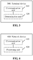
- FIG. 3 is a schematic block diagram of a terminal device 300 according to an embodiment of the disclosure. As shown in FIG. 3 , the terminal device 300 includes a communication unit 310. The communication unit 310 is configured to:
- the network device may indicate the working frequency band attribute or system attribute of the network device to the terminal device, and the terminal device may determine whether the working frequency band of the network device is the licensed frequency band or the unlicensed frequency band according to the working frequency band attribute indicated by the network device and thus may correspondingly perform an operation in the licensed frequency band or the unlicensed frequency band, or, the terminal device may determine whether the network device works in the licensed frequency band system or the unlicensed frequency band system according to the system attribute indicated by the network device and thus may correspondingly perform an operation in the licensed frequency band system or the unlicensed frequency band system. Therefore, effective data transmission is implemented.
- the indication information may be any one of a PSS in an SSB, a PBCH in the SSB or RRC signaling.
- the terminal device may further include a determination unit 320, configured to determine the working frequency band attribute or system attribute of the network device based on a sequence configured to generate the indication information.
- the sequence configured to generate the indication information may be a first sequence when the working frequency band of the network device is the licensed frequency band or the network device works in the licensed frequency band system, the sequence configured to generate the indication information may be a second sequence when the working frequency band of the network device is the unlicensed frequency band or the network device works in the unlicensed frequency band system, and the first sequence and the second sequence may be different sequences.
- the different sequences may have different cyclic shift values.
- the terminal device may further include a determination unit 320, configured to determine the working frequency band attribute or system attribute of the network device according to a DMRS sequence for demodulating the indication information.
- a determination unit 320 configured to determine the working frequency band attribute or system attribute of the network device according to a DMRS sequence for demodulating the indication information.
- the DMRS sequence for demodulating the indication information may be a first DMRS sequence when the working frequency band of the network device is the licensed frequency band or the network device works in the licensed frequency band system
- the DMRS sequence for demodulating the indication information may be a second DMRS sequence when the working frequency band of the network device is the unlicensed frequency band or the network device works in the unlicensed frequency band system
- the first DMRS sequence and the second DMRS sequence may be different DMRS sequences.
- the different DMRS sequences may have different initial scrambling sequences.
- the indication information may contain an attribute identifier, and the attribute identifier may represent the working frequency band attribute or system attribute of the network device.
- the terminal device may further include a determination unit 320, configured to determine the working frequency band attribute or system attribute of the network device according to a value of the attribute identifier contained in the indication information.
- the value of the attribute identifier may be a first numerical value when the working frequency band of the network device is the licensed frequency band or the network device works in the licensed frequency band system, the value of the attribute identifier may be a second numerical value when the working frequency band of the network device is the unlicensed frequency band or the network device works in the unlicensed frequency band system, and the first numerical value may be different from the second numerical value.
- the communication unit 310 is specifically configured to perform communication with the network device according to the working frequency band attribute or the system attribute and in an LBT manner.
- terminal device 300 may execute corresponding operations executed by the terminal device in the method 200 and, for simplicity, will not be elaborated herein.
- FIG. 4 is a schematic block diagram of a network device 400 according to an embodiment of the disclosure.
- the network device 400 includes a communication unit 410, configured to:
- the network device may indicate the working frequency band attribute or system attribute of the network device to the terminal device, and the terminal device may determine whether the working frequency band of the network device is the licensed frequency band or the unlicensed frequency band according to the working frequency band attribute indicated by the network device and thus may correspondingly perform an operation in the licensed frequency band or the unlicensed frequency band, or, the terminal device may determine whether the network device works in the licensed frequency band system or the unlicensed frequency band system according to the system attribute indicated by the network device and thus may correspondingly perform an operation in the licensed frequency band system or the unlicensed frequency band system. Therefore, effective data transmission is implemented.
- the indication information may be any one of a PSS in an SSB, a PBCH in the SSB, or RRC signaling.
- the network device may further include a processing unit 420, configured to determine a sequence configured to generate the indication information according to the working frequency band attribute or the system attribute of the network device and generate the indication information based on the sequence.
- a processing unit 420 configured to determine a sequence configured to generate the indication information according to the working frequency band attribute or the system attribute of the network device and generate the indication information based on the sequence.
- the sequence configured to generate the indication information may be a first sequence when the working frequency band of the network device is the licensed frequency band or the network device works in the licensed frequency band system, the sequence configured to generate the indication information may be a second sequence when the working frequency band of the network device is the unlicensed frequency band or the network device works in the unlicensed frequency band system, and the first sequence and the second sequence may be different sequences.
- the different sequences may have different cyclic shift values.
- the network device may further include a processing unit 420, configured to determine a DMRS sequence configured to modulate the indication information according to the working frequency band attribute or the system attribute of the network device and modulate the indication information based on the DMRS sequence.
- a processing unit 420 configured to determine a DMRS sequence configured to modulate the indication information according to the working frequency band attribute or the system attribute of the network device and modulate the indication information based on the DMRS sequence.
- the DMRS sequence for demodulating the indication information may be a first DMRS sequence when the working frequency band of the network device is the licensed frequency band or the network device works in the licensed frequency band system
- the DMRS sequence for demodulating the indication information may be a second DMRS sequence when the working frequency band of the network device is the unlicensed frequency band or the network device works in the unlicensed frequency band system
- the first DMRS sequence and the second DMRS sequence may be different DMRS sequences.
- the different DMRS sequences may have different initial scrambling sequences.
- the indication information may contain an attribute identifier, and the attribute identifier may represent the working frequency band attribute or system attribute of the network device.
- the network device may further include a processing unit 420, configured to determine the attribute identifier contained in the indication information according to the working frequency band attribute or the system attribute of the network device.
- the value of the attribute identifier may be a first numerical value when the working frequency band of the network device is the licensed frequency band or the network device works in the licensed frequency band system, the value of the attribute identifier may be a second numerical value when the working frequency band of the network device is the unlicensed frequency band or the network device works in the unlicensed frequency band system, and the first numerical value may be different from the second numerical value.
- the network device 400 may perform corresponding operations executed by the network device in the method 200 and, for simplicity, will not be elaborated herein.
- FIG. 5 is a schematic structure diagram of a communication device 500 according to an embodiment of the disclosure.
- the communication device includes a processor 510, a transceiver 520 and a memory 530.
- the processor 510, the transceiver 520 and the memory 530 communicate with one another through an internal connecting path.
- the memory 530 is configured to store instructions
- the processor 510 is configured to execute the instructions stored in the memory 530 to control the transceiver 520 to receive a signal or send a signal.
- the processor 510 may call the program codes stored in the memory 530 to perform corresponding operations, executed by a terminal device, in the method 200. For similarity, elaborations are omitted herein.
- the processor 510 may call the program codes stored in the memory 530 to perform corresponding operations, executed by a network device, in the method 200. For similarity, elaborations are omitted herein.
- the processor in the embodiment of the disclosure may be an integrated circuit chip and has a signal processing capability.
- each step of the method embodiment may be completed by an integrated logical circuit of hardware in the processor or instructions in a software form.
- the processor may be a universal processor, a Digital Signal Processor (DSP), an Application Specific Integrated Circuit (ASIC), a Field Programmable Gate Array (FPGA) or another programmable logical device, discrete gate or transistor logical device and discrete hardware component.
- DSP Digital Signal Processor
- ASIC Application Specific Integrated Circuit
- FPGA Field Programmable Gate Array
- Each method, step and logical block diagram disclosed in the embodiments of the disclosure may be implemented or executed.
- the universal processor may be a microprocessor or the processor may also be any conventional processor and the like.
- the steps of the method disclosed in combination with the embodiments of the disclosure may be directly embodied to be executed and completed by a hardware decoding processor or executed and completed by a combination of hardware and software modules in the decoding processor.
- the software module may be located in a mature storage medium in this field such as a Random Access Memory (RAM), a flash memory, a Read-Only Memory (ROM), a Programmable ROM (PROM) or Electrically Erasable PROM (EEPROM) and a register.
- RAM Random Access Memory
- ROM Read-Only Memory
- PROM Electrically Erasable PROM
- the storage medium is located in a memory, and the processor reads information in the memory, and completes the steps of the methods in combination with hardware.
- the memory in the embodiment of the disclosure may be a volatile memory or a nonvolatile memory, or may include both the volatile and nonvolatile memories.
- the nonvolatile memory may be a ROM, a PROM, an Erasable PROM (EPROM), an EEPROM or a flash memory.
- the volatile memory may be a RAM, and can be used as an external high-speed cache.
- RAMs in various forms may be adopted, such as a Static RAM (SRAM), a Dynamic RAM (DRAM), a Synchronous DRAM (SDRAM), a Double Data Rate SDRAM (DDRSDRAM), an Enhanced SDRAM (ESDRAM), a Synchlink DRAM (SLDRAM) and a Direct Rambus RAM (DR RAM).
- SRAM Static RAM
- DRAM Dynamic RAM
- SDRAM Synchronous DRAM
- DDRSDRAM Double Data Rate SDRAM
- ESDRAM Enhanced SDRAM
- SLDRAM Synchlink DRAM
- DR RAM Direct Rambus RAM
- FIG. 6 is a schematic structure diagram of a system chip according to an embodiment of the disclosure.
- the system chip 600 of FIG. 6 includes an input interface 601, an output interface 602, at least one processor 603 and a memory 604.
- the input interface 601, the output interface 602, the processor 603 and the memory 604 can be connected with one another through an internal connecting path.
- the processor 603 is configured to execute codes in the memory 604.
- the processor 603 may implement corresponding operations executed by a terminal device in the method 200.
- the processor 603 may implement corresponding operations executed by a terminal device in the method 200.
- elaborations are omitted herein.
- the processor 603 may implement corresponding operations executed by a network device in the method 200.
- the processor 603 may implement corresponding operations executed by a network device in the method 200.
- elaborations are omitted herein.
- B corresponding to A represents that B is associated with A and B may be determined according to A. It is also to be understood that determining B according to A does not mean that B is determined only according to A. B also may be determined according to A and/or other information.
- the disclosed system, device and method may be implemented in another manner.
- the device embodiments described above are only schematic.
- division of the units is only logic function division, and other division manners may be adopted during practical implementation.
- multiple units or components may be combined or integrated into another system, or some characteristics may be neglected or not executed.
- coupling or direct coupling or communication connection between each displayed or discussed component may be indirect coupling or communication connection, implemented through some interfaces, of the device or the units, and may be electrical and mechanical or adopt other forms.
- the units described as separate parts may be or may not be physically separated, and parts displayed as units may be or may not be physical units, and namely may be located in the same place, or may also be distributed to multiple network units. Part or all of the units may be selected to achieve the purpose of the solutions of the embodiments according to a practical requirement.
- each functional unit in each embodiment of the disclosure may be integrated into a processing unit, each unit may also physically exist independently, and two or more than two units may also be integrated into a unit.
- the function may also be stored in a computer-readable storage medium.
- the technical solutions of the disclosure substantially or parts making contributions to the conventional art or part of the technical solutions may be embodied in form of software product, and the computer software product is stored in a storage medium, including a plurality of instructions configured to enable a computer device (which may be a personal computer, a server, a network device or the like) to execute all or part of the steps of the method in each embodiment of the disclosure.
- the storage medium includes: various media capable of storing program codes such as a U disk, a mobile hard disk, a ROM, a RAM, a magnetic disk or an optical disk.
Landscapes
- Engineering & Computer Science (AREA)
- Signal Processing (AREA)
- Computer Networks & Wireless Communication (AREA)
- Databases & Information Systems (AREA)
- Computer Security & Cryptography (AREA)
- Mobile Radio Communication Systems (AREA)
Abstract
Description
- Embodiments of the disclosure relate to the field of communication, and more particularly to a communication method and device.
- A 5th-Generation (5G) system supports data transmission in unlicensed frequency bands. A terminal device may execute different operations for communication in an unlicensed frequency bands system and a licensed frequency bands system. In an example, in an unlicensed frequency bands system, a terminal device may need to communicate in a listen before talk (LBT) manner. Namely, whether a channel is idle or not is listened before data is sent and the data can be sent only when it is determined that the channel is idle.
- However, out of different considerations, organizations for spectrum supervision and allocation in different countries make different spectrum plans and allocations. In an example, 3.5GHz is a licensed New Radio (NR) frequency band in China but is an unlicensed frequency band in the United States. Similarly, 37GHz may be classified as a licensed NR frequency band in China but may be classified as an unlicensed frequency band in the United States. Therefore, the difference in spectrum allocation may cause a terminal device to not effectively perform communication when roaming in different countries or regions.
- The embodiments of the disclosure provide a communication method and device. When a terminal device roams in different countries or regions, the terminal device can effectively communicate even though different spectrum allocations are adopted for licensed frequency bands and unlicensed frequency bands in different countries or regions.
- A first aspect provides a communication method, which may include that:
- a terminal device receives indication information from a network device, the indication information being configured to indicate a working frequency band attribute or system attribute of the network device, the working frequency band attribute being configured to represent whether a working frequency band of the network device is a licensed frequency band or an unlicensed frequency band and the system attribute being configured to represent whether the network device works in a licensed frequency band system or an unlicensed frequency band system; and
- the terminal device performs communication with the network device according to the working frequency band attribute or the system attribute.
- Accordingly, the network device can indicate the working frequency band attribute or system attribute of the network device to the terminal device, and the terminal device can determine whether the working frequency band of the network device is the licensed frequency band or the unlicensed frequency band according to the working frequency band attribute indicated by the network device and thus can perform an operation in the licensed frequency band or the unlicensed frequency band, or, the terminal device can determine whether the network device works in the licensed frequency band system or the unlicensed frequency band system according to the system attribute indicated by the network device and thus can perform an operation in the licensed frequency band system or the unlicensed frequency band system. Therefore, effective data transmission is implemented.
- In combination with the first aspect, in a possible implementation mode of the first aspect, the indication information may be any one of a primary synchronous signal (PSS) in a synchronous signal block (SSB), a physical broadcast channel (PBCH) in the SSB, or radio resource control (RRC) signaling.
- In combination with the first aspect or any abovementioned possible implementation mode, in another possible implementation mode of the first aspect, when the indication information is the PSS, before the terminal device performs communication with the network device according to the working frequency band attribute or the system attribute, the method may further include that: the terminal device determines the working frequency band attribute or system attribute of the network device based on a sequence configured to generate the indication information.
- The sequence configured to generate the indication information may be a first sequence when the working frequency band of the network device is the licensed frequency band or the network device works in the licensed frequency band system. The sequence configured to generate the indication information may be a second sequence when the working frequency band of the network device is the unlicensed frequency band or the network device works in the unlicensed frequency band system. The first sequence and the second sequence may be different sequences.
- In combination with the first aspect or any abovementioned possible implementation mode, in another possible implementation mode of the first aspect, the different sequences may have different cyclic shift values.
- In combination with the first aspect or any abovementioned possible implementation mode, in another possible implementation mode of the first aspect, when the indication information is the PBCH, before the terminal device performs communication with the network device according to the working frequency band attribute or the system attribute, the method may further include that: the terminal device determines the working frequency band attribute or system attribute of the network device based on a demodulation reference signal (DMRS) sequence for demodulating the indication information.
- The DMRS sequence for demodulating the indication information may be a first DMRS sequence when the working frequency band of the network device is the licensed frequency band or the network device works in the licensed frequency band system, the DMRS sequence for demodulating the indication information may be a second DMRS sequence when the working frequency band of the network device is the unlicensed frequency band or the network device works in the unlicensed frequency band system, and the first DMRS sequence and the second DMRS sequence may be different DMRS sequences.
- In combination with the first aspect or any abovementioned possible implementation mode, in another possible implementation mode of the first aspect, the different DMRS sequences have different initial scrambling sequences.
- In combination with the first aspect or any abovementioned possible implementation mode, in another possible implementation mode of the first aspect, the indication information may contain an attribute identifier, and the attribute identifier may represent the working frequency band attribute or system attribute of the network device. Before the terminal device performs communication with the network device according to the working frequency band attribute or the system attribute, the method may further include that: the terminal device determines the working frequency band attribute or system attribute of the network device according to a value of the attribute identifier contained in the indication information.
- The value of the identifier may be a first numerical value when the working frequency band of the network device is the licensed frequency band or the network device works in the licensed frequency band system, the value of the identifier may be a second numerical value when the working frequency band of the network device is the unlicensed frequency band or the network device works in the unlicensed frequency band system, and the first numerical value may be different from the second numerical value.
- In combination with the first aspect or any abovementioned possible implementation mode, in another possible implementation mode of the first aspect, when the working frequency band of the network device is the unlicensed frequency band or the network device works in the unlicensed frequency band system, the operation that the terminal device performs communication with the network device may include that: the terminal device performs communication with the network device in an LBT manner.
- A second aspect provides a communication method, which may include that:
- a network device sends indication information to a terminal device, the indication information being configured to indicate a working frequency band attribute or system attribute of the network device, the working frequency band attribute being configured to represent whether a working frequency band of the network device is a licensed frequency band or an unlicensed frequency band and the system attribute being configured to represent whether the network device works in a licensed frequency band system or an unlicensed frequency band system; and
- the network device performs communication with the terminal device according to the working frequency band attribute or the system attribute.
- Accordingly, the network device can indicate the working frequency band attribute or system attribute of the network device to the terminal device, and the terminal device can determine whether the working frequency band of the network device is the licensed frequency band or the unlicensed frequency band according to the working frequency band attribute indicated by the network device and thus can perform an operation in the licensed frequency band or the unlicensed frequency band, or, the terminal device can determine whether the network device works in the licensed frequency band system or the unlicensed frequency band system according to the system attribute indicated by the network device and thus can perform an operation in the licensed frequency band system or the unlicensed frequency band system. Therefore, effective data transmission is implemented.
- In combination with the second aspect, in a possible implementation mode of the second aspect, the indication information may be any one of a PSS in an SSB, a PBCH in the SSB, or RRC signaling.
- In combination with the second aspect or any abovementioned possible implementation mode, in another possible implementation mode of the second aspect, when the indication information is the PSS, before the network device sends the indication information to the terminal device, the method may further include that: the network device determines a sequence configured to generate the indication information according to the working frequency band attribute or the system attribute of the network device and generates the indication information based on the sequence.
- The sequence configured to generate the indication information may be a first sequence when the working frequency band of the network device is the licensed frequency band or the network device works in the licensed frequency band system, the sequence configured to generate the indication information may be a second sequence when the working frequency band of the network device is the unlicensed frequency band or the network device works in the unlicensed frequency band system, and the first sequence and the second sequence may be different sequences.
- In combination with the second aspect or any abovementioned possible implementation mode, in another possible implementation mode of the second aspect, the different sequences may have different cyclic shift values.
- In combination with the second aspect or any abovementioned possible implementation mode, in another possible implementation mode of the second aspect, when the indication information is the PBCH, before the network device sends the indication information to the terminal device, the method may further include that: the network device determines a DMRS sequence configured to modulate the indication information according to the working frequency band attribute or the system attribute of the network device and modulates the indication information based on the DMRS sequence.
- The DMRS sequence for demodulating the indication information may be a first DMRS sequence when the working frequency band of the network device is the licensed frequency band or the network device works in the licensed frequency band system, the DMRS sequence for demodulating the indication information may be a second DMRS sequence when the working frequency band of the network device is the unlicensed frequency band or the network device works in the unlicensed frequency band system, and the first DMRS sequence and the second DMRS sequence may be different DMRS sequences.
- In combination with the second aspect or any abovementioned possible implementation mode, in another possible implementation mode of the second aspect, the different DMRS sequences may have different initial scrambling sequences.
- In combination with the second aspect or any abovementioned possible implementation mode, in another possible implementation mode of the second aspect, the indication information may contain an attribute identifier, and the attribute identifier may represent the working frequency band attribute or system attribute of the network device. Before the network device sends the indication information to the terminal device, the method may further include that: the network device determines the attribute identifier contained in the indication information according to the working frequency band attribute or the system attribute of the network device.
- A value of the identifier may be a first numerical value when the working frequency band of the network device is the licensed frequency band or the network device works in the licensed frequency band system, the value of the identifier may be a second numerical value when the working frequency band of the network device is the unlicensed frequency band or the network device works in the unlicensed frequency band system, and the first numerical value may be different from the second numerical value.
- A third aspect provides a terminal device, which may execute the operations of a receiving node in the first aspect or any optional implementation mode of the first aspect. Specifically, the terminal device may include modular units configured to execute the operations of the receiving node in the first aspect or any possible implementation mode of the first aspect.
- A fourth aspect provides a network device, which may execute operations of a sending node in the first aspect or any optional implementation mode of the first aspect. Specifically, the network device may include modular units configured to execute the operations of the sending node in the second aspect or any possible implementation mode of the second aspect.
- A fifth aspect provides a terminal device, which includes a processor, a transceiver and a memory. The processor, the transceiver and the memory can communicate with one another through an internal connecting path. The memory is configured to store instructions, and the processor is configured to execute the instructions stored in the memory. When the processor executes the instructions stored in the memory, such execution enables the terminal device to implement the method in the first aspect or any possible implementation mode of the first aspect, or such execution enables the terminal device to act as the terminal device provided in the third aspect.
- A sixth aspect provides a network device, which includes a processor, a transceiver and a memory. The processor, the transceiver and the memory communicate with one another through an internal connecting path. The memory is configured to store instructions, and the processor is configured to execute the instructions stored in the memory. When the processor executes the instructions stored in the memory, such execution enables the network device to implement the method in the second aspect or any possible implementation mode of the second aspect, or such execution enables the network device to act as the network device provided in the fourth aspect.
- A seventh aspect provides a system chip, which includes an input interface, an output interface, a processor and a memory. The processor is configured to execute instructions stored in the memory. When the instructions are executed, the processor may implement the method in the first aspect or any possible implementation mode of the first aspect.
- An eighth aspect provides a system chip, which includes an input interface, an output interface, a processor and a memory. The processor is configured to execute instructions stored in the memory. When the instructions are executed, the processor may implement the method in the second aspect or any possible implementation mode of the second aspect.
- A ninth aspect provides a computer program product including instructions, which runs in a computer to cause the computer to implement the method in the first aspect or any possible implementation mode of the first aspect.
- A tenth aspect provides a computer program product including instructions, which runs in a computer to cause the computer to implement the method in the second aspect or any possible implementation mode of the second aspect.
-
-
FIG. 1 is a schematic diagram of a wireless communication system to which the embodiments of the disclosure are applied. -
FIG. 2 is an interaction flowchart of a communication method according to an embodiment of the disclosure. -
FIG. 3 is a schematic block diagram of a terminal device according to an embodiment of the disclosure. -
FIG. 4 is a schematic block diagram of a network device according to an embodiment of the disclosure. -
FIG. 5 is a schematic structure diagram of a communication device according to an embodiment of the disclosure. -
FIG. 6 is a schematic structure diagram of a system chip according to an embodiment of the disclosure. - The technical solutions of the embodiments of the disclosure may be applied to various communication systems, for example, a Global System of Mobile Communication (GSM), a Code Division Multiple Access (CDMA) system, a Wideband Code Division Multiple Access (WCDMA) system, a General Packet Radio Service (GPRS), a Long Term Evolution (LTE) system, an LTE Frequency Division Duplex (FDD) system, LTE Time Division Duplex (TDD), a Universal Mobile Telecommunication System (UMTS), a Worldwide Interoperability for Microwave Access (WiMAX) communication system or a future 5G system.
-
FIG. 1 illustrates awireless communication system 100 to which the embodiments of the disclosure are applied. Thewireless communication system 100 may include anetwork device 110. Thenetwork device 110 may be a device capable of communicating with a terminal device. Thenetwork device 110 may provide communication coverage for a specific geographical region and can communicate with a terminal device (for example, User Equipment (UE)) in the coverage. Optionally, thenetwork device 110 may be a Base Transceiver Station (BTS) in a GSM or CDMA system, may also be a NodeB (NB) in a WCDMA system, or may be an Evolutional Node B (eNB or eNodeB) in a LTE system or a wireless controller in a Cloud Radio Access Network (CRAN). Or the network device may be a relay station, an access point, a vehicle device, a wearable device, a network-side device in a future 5G network, a network device in a future evolved Public Land Mobile Network (PLMN) or the like. - The
wireless communication system 100 further includes at least oneterminal device 120 within the coverage of thenetwork device 110. Theterminal device 120 may be mobile or fixed. Optionally, theterminal device 120 may be an access terminal, UE, a user unit, a user station, a mobile station, a mobile radio station, a remote station, a remote terminal, a mobile device, a user terminal, a terminal, a wireless communication device, a user agent or a user device. The access terminal may be a cell phone, a cordless phone, a Session Initiation Protocol (SIP) phone, a Wireless Local Loop (WLL) station, a Personal Digital Assistant (PDA), a handheld device with a wireless communication function, a computing device, another processing device connected to a wireless modem, a vehicle device, a wearable device, a terminal device in a future 5G network, a terminal device in a future evolved PLMN or the like. Optionally, theterminal device 120 can also perform Device to Device (D2D) communication. - One network device and two terminal devices are exemplarily shown in
FIG. 1 . Optionally, thewireless communication system 100 may include multiple network devices and another number of terminal devices, other than two, may be included in coverage of each network device. There are no limits made thereto in the embodiments of the disclosure. - Optionally, the
wireless communication system 100 may further include another network entity such as a network controller, a mobility management entity and so on. There are no limits made thereto in the embodiments of the disclosure. - Organizations for spectrum supervision and allocation in different countries make different spectrum plans and allocations out of different considerations. In an example, 3.5GHz is a licensed NR frequency band in China but is an unlicensed frequency band in the United States. For another example, 37GHz may be classified as a licensed NR frequency band in China but may be classified as an unlicensed frequency band in the United States.
- Such differences in spectrum allocation may cause a situation that, when a terminal device roams in different countries or regions, unlicensed frequency band systems are deployed in some countries or regions while licensed frequency band systems are deployed in some other countries or regions in a same frequency band (for example, a 3.5GHz frequency band). In an unlicensed frequency band, due to an LBT mechanism, a synchronous signal block (SSB or SS Block) bearing a synchronous signal and a physical broadcast channel (PBCH) may be sent successfully or unsuccessfully at a certain probability. Remaining minimum system information (RMSI) associated with the SSB may also be sent successfully or unsuccessfully at a certain probability. The LBT mechanism needs to be adopted for uplink transmission of the terminal device. Uplink transmission of the terminal device needs to meet a requirement on restriction of a power spectral density and the like. Therefore, an operation performed by a terminal device in an unlicensed frequency band system may be different from an operation performed by the terminal device in a licensed frequency band system.
- Therefore, if different spectrum division manners are adopted in different countries or regions, a terminal device cannot effectively communicate when the terminal device roams in different countries or regions.
- Therefore, it is proposed in the embodiments of the disclosure that a network device indicates a working frequency band attribute or system attribute of the network device to a terminal device, and then the terminal device determines whether a working frequency band of the network device is a licensed frequency band or an unlicensed frequency band according to the working frequency band attribute indicated by the network device and thus can correspondingly perform an operation in the licensed frequency band or the unlicensed frequency band, or, the terminal device determines whether the network device works in a licensed frequency band system or an unlicensed frequency band system according to the system attribute indicated by the network device and thus can correspondingly perform an operation in the licensed frequency band system or the unlicensed frequency band system. Therefore, effective data transmission is implemented.
-
FIG. 2 is an interaction flowchart of a communication method according to an embodiment of the disclosure. A terminal device shown inFIG. 2 may be, for example, theterminal device 120 as shown inFIG. 1 . A network device shown inFIG. 2 may be, for example, thenetwork device 110 as shown inFIG. 1 . As shown inFIG. 2 , the communication method may include part or all of the following contents. - In 210, the network device sends indication information to the terminal device, the indication information indicating a working frequency band attribute or system attribute of the network device.
- The working frequency band attribute may represent whether a working frequency band of the network device is a licensed frequency band or an unlicensed frequency band, and the system attribute may represent whether the network device works in a licensed frequency band system or an unlicensed frequency band system.
- In 220, the terminal device receives the indication information from the network device.
- In 230, the terminal device performs communication with the network device according to the working frequency band attribute or the system attribute.
- In 240, the network device performs communication with the terminal device according to the working frequency band attribute or the system attribute.
- Specifically, the terminal device may receive the indication information from the network device, and there is made such a hypothesis that the indication information indicates the working frequency band attribute of the network device. The working frequency band attribute of the network device mayrepresent whether a frequency band supported by the network device is a licensed frequency band or an unlicensed frequency band. When the working frequency band of the network device is the licensed frequency band, the terminal device may perform a corresponding communication operation in the licensed frequency band, for example, performing data transmission with the network device based on a resource configured by the network device. When the working frequency band of the network device is the unlicensed frequency band, the terminal device may perform a corresponding communication operation in the unlicensed frequency band, for example, listening whether a channel is idle or not in an LBT manner and performing data transmission after determining that the channel is idle.
- The terminal device may receive the indication information from the network device, and there is made such a hypothesis that the indication information indicates the system attribute of the network device. The system attribute of the network device may represent whether a system where the network device is located is the unlicensed frequency band system (an unlicensed NR system) or the licensed frequency band system (a licensed NR system). When the network device works in the licensed frequency band system, the terminal device may perform the corresponding communication operation in the licensed frequency band, for example, performing data transmission with the network device based on a resource configured by the network device. When the network device works in the unlicensed frequency band system, the terminal device may perform a corresponding communication operation in the unlicensed frequency band, for example, listening whether a channel is idle or not based on the LBT manner and performing data transmission after determining that the channel is idle.
- It is to be understood that: the network device works in the licensed frequency band system when the working frequency band of the network device is the licensed frequency band, and the network device works in the unlicensed frequency band system when the working frequency band of the network device is the unlicensed frequency band.
- Accordingly, the network device may indicate the working frequency band attribute or system attribute of the network device to the terminal device, and the terminal device may determine whether the working frequency band of the network device is the licensed frequency band or the unlicensed frequency band according to the working frequency band attribute indicated by the network device and thus can correspondingly perform an operation in the licensed frequency band or the unlicensed frequency band, or, the terminal device may determines whether the network device works in the licensed frequency band system or the unlicensed frequency band system according to the system attribute indicated by the network device and thus can correspondingly perform an operation in the licensed frequency band system or the unlicensed frequency band system. Therefore, effective data transmission is implemented.
- Optionally, the indication information may include, but not limited to any one of a PSS in an SSB (or Synchronization Signal (SS) block), a Secondary Synchronization Signal (SSS) in the SSB, a PBCH in the SSB, RRC signaling, RMSI and Other System Information (OSI).
- That is, the network device may indicate the working frequency band attribute or system attribute of the network device to the terminal device through information such as the PSS, the SSS, the PBCH, the RMSI or the OSI. Specifically, the network device may implicitly or explicitly indicate the working frequency band attribute or system attribute of the network device through the information.
- The implicit indication manner of the network device will specifically be described below with the conditions that the indication information is the PSS or the PBCH as examples.
- Optionally, the indication information is the PSS.
- Before 210, the network device determines, according to the working frequency band attribute or the system attribute of the network device, a sequence configured to generate the indication information and generates the indication information based on the sequence.
- Correspondingly, before 220, the terminal device may determine the working frequency band attribute or system attribute of the network device based on the sequence configured to generate the indication information.
- The sequence configured to generate the indication information may be a first sequence when the working frequency band of the network device is the licensed frequency band or the network device works in the licensed frequency band system, the sequence configured to generate the indication information may be a second sequence when the working frequency band of the network device is the unlicensed frequency band or the network device works in the unlicensed frequency band system, and the first sequence and the second sequence are different sequences.
- That is, under situations that the working frequency band of the network device is the licensed frequency band and the working frequency band of the network device is the unlicensed frequency band, the network device may adopt different sequences to generate the PSS. Or, under situations that the network device works in the licensed frequency band system and the network device works in the unlicensed frequency band system, the network device may adopt different sequences to generate the PSS. The terminal device may determine the working frequency band attribute or system attribute of the network device based on the sequence for generation of the PSS.
- Furthermore, cyclic shift values of the different sequences are optionally different.
- In an example, when the working frequency band of the network device is the licensed frequency band or the network device works in the licensed frequency band system, the first sequence configured to generate the PSS is:

- where
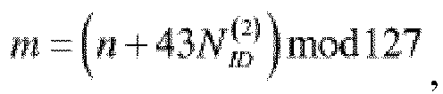
- where x(i+7) = x((i+4)+x(i))mod2, and [x(6) x(5) x(4) x(3) x(2) x(1)]=[1 1 10110].
- It can be seen that the sequence m is adopted to generate the PSS, and three cyclic shift values in terms of frequency are 0, 43 and 86 respectively.
- When the working frequency band of the network device is the unlicensed frequency band or the network device works in the unlicensed frequency band system, the second sequence configured to generate the PSS is:

where
- In such case, the three cyclic shift values in terms of frequency are 0+offset, 43+offset and 86+offset respectively. Herein, if offset=22, the three cyclic shift values are 22, 65 and 108 respectively.
- Then, the terminal device can determine the sequence dPSS for generation of the PSS by detecting the PSS sent by the network device. For different working frequency band attributes or different system attributes of the network device, the sequences m are different, and thus the sequences dPSS are also different. Therefore, the terminal device can determine the working frequency band attribute or system attribute of the network device according to different sequences dPSS .
- Before 210, the network device determines, according to the working frequency band attribute or the system attribute of the network device, a DMRS sequence configured to modulate the indication information and modulates the indication information based on the DMRS sequence.
- Correspondingly, before 220, the terminal device can determine the working frequency band attribute or system attribute of the network device based on the DMRS sequence for demodulating the indication information.
- The sequence configured to generate the indication information may be a first sequence when the working frequency band of the network device is the licensed frequency band or the network device works in the licensed frequency band system, the sequence configured to generate the indication information may be a second sequence when the working frequency band of the network device is the unlicensed frequency band or the network device works in the unlicensed frequency band system, and the first sequence and the second sequence may be different sequences.
- That is, under situations that the working frequency band of the network device is the licensed frequency band and the working frequency band of the network device is the unlicensed frequency band, the network device may adopt different DMRS sequences to modulate the indication information. Or, under situations that the network device works in the licensed frequency band system and the network device works in the unlicensed frequency band system, the network device may adopt different DMRS sequences to modulate the indication information. The terminal device may determine the working frequency band attribute or system attribute of the network device based on the DMRS sequence for successful demodulation of the PBCH.
- Furthermore, initial scrambling sequences of the different DMRS sequences are optionally different.
- In an example, when the working frequency band of the network device is the licensed frequency band or the network device works in the licensed frequency band system, the first DMRS sequence configured to generate the PBCH is:

- There is made such a hypothesis that the initial scrambling sequence of the sequence r(m) is:

wherei SBB =4iSSB +nhf , nhf is a half frame serial number in a subframe for transmission of the PBCH, and i SSB is the smallest significant bit size of an SSB index. - When the working frequency band of the network device is the unlicensed frequency band or the network device works in the unlicensed frequency band system, the second sequence configured to generate the PBCH is:

- However, the initial scrambling sequence of the sequence r(m) is set to be:

wherei SBB =4iSSB + nhf , nhf is the half frame serial number in the subframe for transmission of the PBCH, and i SSB is the smallest significant bit size of the SSB index. - Then, the terminal device can determine the sequence for generation of the PBCH by detecting the PBCH from the network device. For different working frequency band attributes or different system attributes of the network device, initial sequences in the sequences r(m) are different, and thus the sequences r(m) are also different. Therefore, the terminal device can determine the working frequency band attribute or system attribute of the network device according to different sequences r(m).
- It is to be understood that, in the first manner, the implicit indication manner of the network device is described only with the sequence m for generation of the PSS and the DMRS sequence for modulation or demodulation of the PBCH as examples. The disclosure is not limited thereto and a manner of adopting another physical channel or another sequence for implicit indication shall also fall within the scope of protection of the disclosure.
- Optionally, the indication information may contain an attribute identifier, and the attribute identifier may represent the working frequency band attribute or system attribute of the network device.
- Before 210, the network device may determine the attribute identifier contained in the indication information according to the working frequency band attribute or the system attribute of the network device.
- Correspondingly, before 220, the terminal device may determine the working frequency band attribute or system attribute of the network device according to a value of the attribute identifier contained in the indication information.
- The value of the identifier may be a first numerical value when the working frequency band of the network device is the licensed frequency band or the network device works in the licensed frequency band system, the value of the identifier is a second numerical value when the working frequency band of the network device may be the unlicensed frequency band or the network device works in the unlicensed frequency band system, and the first numerical value may be different from the second numerical value.
- That is, under situations that the working frequency band of the network device is the licensed frequency band and the working frequency band of the network device is the unlicensed frequency band respectively, the attribute identifier contained in the indication information has different values. Under situations that the network device works in the licensed frequency band system and the network device works in the unlicensed frequency band system, the attribute identifier contained in the indication information also has different values. The terminal device may determine the working frequency band attribute or system attribute of the network device according to the value of the attribute identifier contained in the indication information.
- In an example, a reserved bit in the PBCH, like a reserved bit in a payload field in the PBCH, may be adopted. When a value of the bit is 1, it is indicated that the working frequency band of the network device is the unlicensed frequency band or the network device works in the unlicensed frequency band system. When the value of the bit is 0, it is indicated that the working frequency band of the network device is the licensed frequency band or the network device works in the licensed frequency band system.
- In another example, the attribute identifier may be added to the PBCH, the RMSI or the OSI. When the value of the attribute identifier is 1, it is indicated that the working frequency band of the network device is the unlicensed frequency band or the system of the network device is the unlicensed frequency band system. When the value of the attribute identifier is 0, it is indicated that the working frequency band of the network device is the licensed frequency band or the system of the network device is the licensed frequency band system.
- Optionally, when the working frequency band of the network device is the unlicensed frequency band or the network device works in the unlicensed frequency band system, the operation in 240 that the terminal device performs communication with the network device may include that: the terminal device performs communication with the network device based on an LBT mechanism.
- Since the working frequency band of the network device is the unlicensed frequency band or the network device works in the unlicensed frequency band system, the terminal device needs to listen whether a channel is idle or not based on the LBT mechanism, and perform communication with the network device when determining that the channel is idle.
- Therefore, even though different spectrum division manners are adopted in different countries or regions a terminal device can effectively acquire whether a frequency band of a network presently to access is an unlicensed frequency band or a licensed frequency band and thus perform a corresponding operation to implement effective data transmission in different frequency bands when the terminal device roams in different countries or regions.
- It is to be understood that, in various embodiments of the disclosure, the sequence number of each process does not mean an execution order and the execution order of each process should be determined by its function and an internal logic and should not form any limit to an implementation process of the embodiments of the disclosure.
- The communication method according to the embodiments of the disclosure is described above in detail and a device according to the embodiments of the disclosure will be described below in combination with
FIG. 5 to FIG. 8 . The technical characteristics described in the method embodiments are applied to the following device embodiments. -
FIG. 3 is a schematic block diagram of aterminal device 300 according to an embodiment of the disclosure. As shown inFIG. 3 , theterminal device 300 includes acommunication unit 310. Thecommunication unit 310 is configured to: - receive indication information from a network device, the indication information indicating a working frequency band attribute or system attribute of the network device, the working frequency band attribute representing whether a working frequency band of the network device is a licensed frequency band or an unlicensed frequency band and the system attribute representing whether the network device works in a licensed frequency band system or an unlicensed frequency band system; and
- perform communication with the network device according to the working frequency band attribute or the system attribute.
- Accordingly, the network device may indicate the working frequency band attribute or system attribute of the network device to the terminal device, and the terminal device may determine whether the working frequency band of the network device is the licensed frequency band or the unlicensed frequency band according to the working frequency band attribute indicated by the network device and thus may correspondingly perform an operation in the licensed frequency band or the unlicensed frequency band, or, the terminal device may determine whether the network device works in the licensed frequency band system or the unlicensed frequency band system according to the system attribute indicated by the network device and thus may correspondingly perform an operation in the licensed frequency band system or the unlicensed frequency band system. Therefore, effective data transmission is implemented. Optionally, the indication information may be any one of a PSS in an SSB, a PBCH in the SSB or RRC signaling.
- Optionally, when the indication information is the PSS, the terminal device may further include a
determination unit 320, configured to determine the working frequency band attribute or system attribute of the network device based on a sequence configured to generate the indication information. - The sequence configured to generate the indication information may be a first sequence when the working frequency band of the network device is the licensed frequency band or the network device works in the licensed frequency band system, the sequence configured to generate the indication information may be a second sequence when the working frequency band of the network device is the unlicensed frequency band or the network device works in the unlicensed frequency band system, and the first sequence and the second sequence may be different sequences.
- Optionally, the different sequences may have different cyclic shift values.
- Optionally, when the indication information is the PBCH, the terminal device may further include a
determination unit 320, configured to determine the working frequency band attribute or system attribute of the network device according to a DMRS sequence for demodulating the indication information. - The DMRS sequence for demodulating the indication information may be a first DMRS sequence when the working frequency band of the network device is the licensed frequency band or the network device works in the licensed frequency band system, the DMRS sequence for demodulating the indication information may be a second DMRS sequence when the working frequency band of the network device is the unlicensed frequency band or the network device works in the unlicensed frequency band system, and the first DMRS sequence and the second DMRS sequence may be different DMRS sequences.
- Optionally, the different DMRS sequences may have different initial scrambling sequences.
- Optionally, the indication information may contain an attribute identifier, and the attribute identifier may represent the working frequency band attribute or system attribute of the network device. The terminal device may further include a
determination unit 320, configured to determine the working frequency band attribute or system attribute of the network device according to a value of the attribute identifier contained in the indication information. - The value of the attribute identifier may be a first numerical value when the working frequency band of the network device is the licensed frequency band or the network device works in the licensed frequency band system, the value of the attribute identifier may be a second numerical value when the working frequency band of the network device is the unlicensed frequency band or the network device works in the unlicensed frequency band system, and the first numerical value may be different from the second numerical value.
- Optionally, when the working frequency band of the network device is the unlicensed frequency band or the network device works in the unlicensed frequency band system, the
communication unit 310 is specifically configured to perform communication with the network device according to the working frequency band attribute or the system attribute and in an LBT manner. - It is to be understood that the
terminal device 300 may execute corresponding operations executed by the terminal device in themethod 200 and, for simplicity, will not be elaborated herein. -
FIG. 4 is a schematic block diagram of anetwork device 400 according to an embodiment of the disclosure. As shown inFIG. 4 , thenetwork device 400 includes acommunication unit 410, configured to: - send indication information to a terminal device, the indication information indicating a working frequency band attribute or system attribute of the network device, the working frequency band attribute representing whether a working frequency band of the network device is a licensed frequency band or an unlicensed frequency band, and the system attribute representing whether the network device works in a licensed frequency band system or an unlicensed frequency band system; and
- perform communication with the terminal device according to the working frequency band attribute or the system attribute.
- Accordingly, the network device may indicate the working frequency band attribute or system attribute of the network device to the terminal device, and the terminal device may determine whether the working frequency band of the network device is the licensed frequency band or the unlicensed frequency band according to the working frequency band attribute indicated by the network device and thus may correspondingly perform an operation in the licensed frequency band or the unlicensed frequency band, or, the terminal device may determine whether the network device works in the licensed frequency band system or the unlicensed frequency band system according to the system attribute indicated by the network device and thus may correspondingly perform an operation in the licensed frequency band system or the unlicensed frequency band system. Therefore, effective data transmission is implemented. Optionally, the indication information may be any one of a PSS in an SSB, a PBCH in the SSB, or RRC signaling.
- Optionally, when the indication information is the PSS, the network device may further include a
processing unit 420, configured to determine a sequence configured to generate the indication information according to the working frequency band attribute or the system attribute of the network device and generate the indication information based on the sequence. - The sequence configured to generate the indication information may be a first sequence when the working frequency band of the network device is the licensed frequency band or the network device works in the licensed frequency band system, the sequence configured to generate the indication information may be a second sequence when the working frequency band of the network device is the unlicensed frequency band or the network device works in the unlicensed frequency band system, and the first sequence and the second sequence may be different sequences.
- Optionally, the different sequences may have different cyclic shift values.
- Optionally, when the indication information is the PBCH, the network device may further include a
processing unit 420, configured to determine a DMRS sequence configured to modulate the indication information according to the working frequency band attribute or the system attribute of the network device and modulate the indication information based on the DMRS sequence. - The DMRS sequence for demodulating the indication information may be a first DMRS sequence when the working frequency band of the network device is the licensed frequency band or the network device works in the licensed frequency band system, the DMRS sequence for demodulating the indication information may be a second DMRS sequence when the working frequency band of the network device is the unlicensed frequency band or the network device works in the unlicensed frequency band system, and the first DMRS sequence and the second DMRS sequence may be different DMRS sequences.
- Optionally, the different DMRS sequences may have different initial scrambling sequences.
- Optionally, the indication information may contain an attribute identifier, and the attribute identifier may represent the working frequency band attribute or system attribute of the network device. The network device may further include a
processing unit 420, configured to determine the attribute identifier contained in the indication information according to the working frequency band attribute or the system attribute of the network device. - The value of the attribute identifier may be a first numerical value when the working frequency band of the network device is the licensed frequency band or the network device works in the licensed frequency band system, the value of the attribute identifier may be a second numerical value when the working frequency band of the network device is the unlicensed frequency band or the network device works in the unlicensed frequency band system, and the first numerical value may be different from the second numerical value.
- It is to be understood that the
network device 400 may perform corresponding operations executed by the network device in themethod 200 and, for simplicity, will not be elaborated herein. -
FIG. 5 is a schematic structure diagram of acommunication device 500 according to an embodiment of the disclosure. As shown inFIG. 5 , the communication device includes aprocessor 510, atransceiver 520 and amemory 530. Herein, theprocessor 510, thetransceiver 520 and thememory 530 communicate with one another through an internal connecting path. Thememory 530 is configured to store instructions, and theprocessor 510 is configured to execute the instructions stored in thememory 530 to control thetransceiver 520 to receive a signal or send a signal. - Optionally, the
processor 510 may call the program codes stored in thememory 530 to perform corresponding operations, executed by a terminal device, in themethod 200. For similarity, elaborations are omitted herein. - Optionally, the
processor 510 may call the program codes stored in thememory 530 to perform corresponding operations, executed by a network device, in themethod 200. For similarity, elaborations are omitted herein. - It is to be understood that the processor in the embodiment of the disclosure may be an integrated circuit chip and has a signal processing capability. In an implementation process, each step of the method embodiment may be completed by an integrated logical circuit of hardware in the processor or instructions in a software form. The processor may be a universal processor, a Digital Signal Processor (DSP), an Application Specific Integrated Circuit (ASIC), a Field Programmable Gate Array (FPGA) or another programmable logical device, discrete gate or transistor logical device and discrete hardware component. Each method, step and logical block diagram disclosed in the embodiments of the disclosure may be implemented or executed. The universal processor may be a microprocessor or the processor may also be any conventional processor and the like. The steps of the method disclosed in combination with the embodiments of the disclosure may be directly embodied to be executed and completed by a hardware decoding processor or executed and completed by a combination of hardware and software modules in the decoding processor. The software module may be located in a mature storage medium in this field such as a Random Access Memory (RAM), a flash memory, a Read-Only Memory (ROM), a Programmable ROM (PROM) or Electrically Erasable PROM (EEPROM) and a register. The storage medium is located in a memory, and the processor reads information in the memory, and completes the steps of the methods in combination with hardware.
- It can be understood that the memory in the embodiment of the disclosure may be a volatile memory or a nonvolatile memory, or may include both the volatile and nonvolatile memories. The nonvolatile memory may be a ROM, a PROM, an Erasable PROM (EPROM), an EEPROM or a flash memory. The volatile memory may be a RAM, and can be used as an external high-speed cache. It is exemplarily but unlimitedly described that RAMs in various forms may be adopted, such as a Static RAM (SRAM), a Dynamic RAM (DRAM), a Synchronous DRAM (SDRAM), a Double Data Rate SDRAM (DDRSDRAM), an Enhanced SDRAM (ESDRAM), a Synchlink DRAM (SLDRAM) and a Direct Rambus RAM (DR RAM). It is to be noted that the memory of a system and method described in the disclosure is intended to include, but not limited to, memories of these and any other proper types.
-
FIG. 6 is a schematic structure diagram of a system chip according to an embodiment of the disclosure. Thesystem chip 600 ofFIG. 6 includes aninput interface 601, anoutput interface 602, at least oneprocessor 603 and amemory 604. Theinput interface 601, theoutput interface 602, theprocessor 603 and thememory 604 can be connected with one another through an internal connecting path. Theprocessor 603 is configured to execute codes in thememory 604. - Optionally, when the codes are executed, the
processor 603 may implement corresponding operations executed by a terminal device in themethod 200. For simplicity, elaborations are omitted herein. - Optionally, when the codes are executed, the
processor 603 may implement corresponding operations executed by a network device in themethod 200. For simplicity, elaborations are omitted herein. - It is to be understood that, in the embodiments of disclosure, "B corresponding to A" represents that B is associated with A and B may be determined according to A. It is also to be understood that determining B according to A does not mean that B is determined only according to A. B also may be determined according to A and/or other information.
- Those of ordinary skill in the art may realize that the units and algorithm steps of each example described in combination with the embodiments disclosed in the disclosure may be implemented by electronic hardware or a combination of computer software and the electronic hardware. Whether these functions are executed in a hardware or software manner depends on specific applications and design constraints of the technical solutions. Professionals may realize the described functions for each specific application by use of different methods, but such realization shall fall within the scope of the disclosure.
- Those skilled in the art may clearly learn about that specific working processes of the system, device and unit described above may refer to the corresponding processes in the method embodiment and will not be elaborated herein for convenient and brief description.
- In some embodiments provided by the disclosure, it is to be understood that the disclosed system, device and method may be implemented in another manner. In an example, the device embodiments described above are only schematic. For example, division of the units is only logic function division, and other division manners may be adopted during practical implementation. In an example, multiple units or components may be combined or integrated into another system, or some characteristics may be neglected or not executed. In addition, coupling or direct coupling or communication connection between each displayed or discussed component may be indirect coupling or communication connection, implemented through some interfaces, of the device or the units, and may be electrical and mechanical or adopt other forms.
- The units described as separate parts may be or may not be physically separated, and parts displayed as units may be or may not be physical units, and namely may be located in the same place, or may also be distributed to multiple network units. Part or all of the units may be selected to achieve the purpose of the solutions of the embodiments according to a practical requirement.
- In addition, each functional unit in each embodiment of the disclosure may be integrated into a processing unit, each unit may also physically exist independently, and two or more than two units may also be integrated into a unit.
- When being realized in form of software functional unit and sold or used as an independent product, the function may also be stored in a computer-readable storage medium. Based on such an understanding, the technical solutions of the disclosure substantially or parts making contributions to the conventional art or part of the technical solutions may be embodied in form of software product, and the computer software product is stored in a storage medium, including a plurality of instructions configured to enable a computer device (which may be a personal computer, a server, a network device or the like) to execute all or part of the steps of the method in each embodiment of the disclosure. The storage medium includes: various media capable of storing program codes such as a U disk, a mobile hard disk, a ROM, a RAM, a magnetic disk or an optical disk.
- The above is only the specific implementation mode of the disclosure and not intended to limit the scope of protection of the disclosure. Any variations or replacements apparent to those skilled in the art within the technical scope disclosed by the disclosure shall fall within the scope of protection of the disclosure. Therefore, the scope of protection of the disclosure shall be subject to the scope of protection of the claims.
Claims (30)
- A communication method, comprising:receiving, by a terminal device, indication information from a network device, wherein the indication information is configured to indicate a working frequency band attribute or a system attribute of the network device, the working frequency band attribute is configured to represent whether a working frequency band of the network device is a licensed frequency band or an unlicensed frequency band and the system attribute is configured to represent whether the network device works in a licensed frequency band system or an unlicensed frequency band system; andperforming, by the terminal device, communication with the network device according to the working frequency band attribute or the system attribute.
- The communication method of claim 1, wherein the indication information is any one of:
a primary synchronous signal (PSS) in a synchronous signal block (SSB), a physical broadcast channel (PBCH) in the SSB or radio resource control (RRC) signaling. - The communication method of claim 1 or 2, wherein when the indication information is the PSS, before performing, by the terminal device, communication with the network device according to the working frequency band attribute or the system attribute, the method further comprises:determining, by the terminal device, the working frequency band attribute or the system attribute of the network device based on a sequence configured to generate the indication information,wherein the sequence configured to generate the indication information is a first sequence when the working frequency band of the network device is the licensed frequency band or the network device works in the licensed frequency band system, and the sequence configured to generate the indication information is a second sequence when the working frequency band of the network device is the unlicensed frequency band or the network device works in the unlicensed frequency band system, the first sequence and the second sequence being different sequences.
- The communication method of claim 3, wherein the different sequences have different cyclic shift values.
- The communication method of claim 1 or 2, wherein when the indication information is the PBCH, before performing, by the terminal device, communication with the network device according to the working frequency band attribute or the system attribute, the method further comprises:determining, by the terminal device, the working frequency band attribute or the system attribute of the network device based on a demodulation reference signal (DMRS) sequence for demodulating the indication information,wherein the DMRS sequence for demodulating the indication information is a first DMRS sequence when the working frequency band of the network device is the licensed frequency band or the network device works in the licensed frequency band system, and the DMRS sequence for demodulating the indication information is a second DMRS sequence when the working frequency band of the network device is the unlicensed frequency band or the network device works in the unlicensed frequency band system, the first DMRS sequence and the second DMRS sequence being different DMRS sequences.
- The communication method of claim 5, wherein the different DMRS sequences have different initial scrambling sequences.
- The communication method of claim 1 or 2, wherein the indication information contains an attribute identifier, and the attribute identifier is configured to represent the working frequency band attribute or the system attribute of the network device; and
before performing, by the terminal device, communication with the network device according to the working frequency band attribute or the system attribute, the method further comprises:determining, by the terminal device, the working frequency band attribute or the system attribute of the network device according to a value of the attribute identifier contained in the indication information,wherein the value of the attribute identifier is a first numerical value when the working frequency band of the network device is the licensed frequency band or the network device works in the licensed frequency band system, and the value of the attribute identifier is a second numerical value when the working frequency band of the network device is the unlicensed frequency band or the network device works in the unlicensed frequency band system, the first numerical value being different from the second numerical value. - The communication method of any one of claims 1-7, wherein, when the working frequency band of the network device is the unlicensed frequency band or the network device works in the unlicensed frequency band system, performing, by the terminal device, communication with the network device comprises:
performing, by the terminal device, communication with the network device in a listen before talk (LBT) manner. - A communication method, comprising:sending, by a network device, indication information to a terminal device, wherein the indication information is configured to indicate a working frequency band attribute or a system attribute of the network device, the working frequency band attribute is configured to represent whether a working frequency band of the network device is a licensed frequency band or an unlicensed frequency band, and the system attribute is configured to represent whether the network device works in a licensed frequency band system or an unlicensed frequency band system; andperforming, by the network device, communication with the terminal device according to the working frequency band attribute or the system attribute.
- The communication method of claim 9, wherein the indication information is any one of:
a primary synchronous signal (PSS) in a synchronous signal block (SSB), a physical broadcast channel (PBCH) in the SSB or radio resource control (RRC) signaling. - The communication method of claim 9 or 10, wherein when the indication information is the PSS, before sending, by the network device, the indication information to the terminal device, the method further comprises:determining, by the network device, a sequence configured to generate the indication information according to the working frequency band attribute or the system attribute of the network device, and generating the indication information based on the sequence,wherein the sequence configured to generate the indication information is a first sequence when the working frequency band of the network device is the licensed frequency band or the network device works in the licensed frequency band system, and the sequence configured to generate the indication information is a second sequence when the working frequency band of the network device is the unlicensed frequency band or the network device works in the unlicensed frequency band system, the first sequence and the second sequence being different sequences.
- The communication method of claim 11, wherein the different sequences have different cyclic shift values.
- The communication method of claim 9 or 10, wherein when the indication information is the PBCH, before sending, by the network device, the indication information to the terminal device, the method further comprises:determining, by the network device, a demodulation reference signal (DMRS) sequence configured to modulate the indication information according to the working frequency band attribute or the system attribute of the network device, and modulating the indication information based on the DMRS sequence,wherein the DMRS sequence for demodulating the indication information is a first DMRS sequence when the working frequency band of the network device is the licensed frequency band or the network device works in the licensed frequency band system, and the DMRS sequence for demodulating the indication information is a second DMRS sequence when the working frequency band of the network device is the unlicensed frequency band or the network device works in the unlicensed frequency band system, the first DMRS sequence and the second DMRS sequence being different DMRS sequences.
- The communication method of claim 13, wherein the different DMRS sequences have different initial scrambling sequences.
- The communication method of claim 9 or 10, wherein the indication information contains an attribute identifier, and the attribute identifier is configured to represent the working frequency band attribute or the system attribute of the network device; and
before sending, by the network device, the indication information to the terminal device, the method further comprises:determining, by the network device, the attribute identifier contained in the indication information according to the working frequency band attribute or the system attribute of the network device,wherein a value of the attribute identifier is a first numerical value when the working frequency band of the network device is the licensed frequency band or the network device works in the licensed frequency band system, and the value of the attribute identifier is a second numerical value when the working frequency band of the network device is the unlicensed frequency band or the network device works in the unlicensed frequency band system, the first numerical value being different from the second numerical value. - A terminal device, comprising:
a communication unit, configured to receive indication information from a network device, wherein the indication information is configured to indicate a working frequency band attribute or a system attribute of the network device, the working frequency band attribute is configured to represent whether a working frequency band of the network device is a licensed frequency band or an unlicensed frequency band and the system attribute is configured to represent whether the network device works in a licensed frequency band system or an unlicensed frequency band system, and further configured to perform communication with the network device according to the working frequency band attribute or the system attribute. - The terminal device of claim 16, wherein the indication information is any one of:
a primary synchronous signal (PSS) in a synchronous signal block (SSB), a physical broadcast channel (PBCH) in the SSB or radio resource control (RRC) signaling. - The terminal device of claim 16 or 17, wherein when the indication information is the PSS, the terminal device further comprises a determination unit, configured to:determine the working frequency band attribute or the system attribute of the network device based on a sequence configured to generate the indication information,wherein the sequence configured to generate the indication information is a first sequence when the working frequency band of the network device is the licensed frequency band or the network device works in the licensed frequency band system, and the sequence configured to generate the indication information is a second sequence when the working frequency band of the network device is the unlicensed frequency band or the network device works in the unlicensed frequency band system, the first sequence and the second sequence being different sequences.
- The terminal device of claim 18, wherein the different sequences have different cyclic shift values.
- The terminal device of claim 16 or 17, wherein when the indication information is the PBCH, the terminal device further comprises a determination unit, configured to:determine the working frequency band attribute or the system attribute of the network device according to a demodulation reference signal (DMRS) sequence for demodulating the indication information,wherein the DMRS sequence for demodulating the indication information is a first DMRS sequence when the working frequency band of the network device is the licensed frequency band or the network device works in the licensed frequency band system, and the DMRS sequence for demodulating the indication information is a second DMRS sequence when the working frequency band of the network device is the unlicensed frequency band or the network device works in the unlicensed frequency band system, the first DMRS sequence and the second DMRS sequence being different DMRS sequences.
- The terminal device of claim 20, wherein the different DMRS sequences have different initial scrambling sequences.
- The terminal device of claim 16 or 17, wherein the indication information contains an attribute identifier, and the attribute identifier is configured to represent the working frequency band attribute or the system attribute of the network device; and
the terminal device further comprises a determination unit, configured to:determine the working frequency band attribute or the system attribute of the network device according to a value of the attribute identifier contained in the indication information,when the value of the attribute identifier is a first numerical value when the working frequency band of the network device is the licensed frequency band or the network device works in the licensed frequency band system, and the value of the attribute identifier is a second numerical value when the working frequency band of the network device is the unlicensed frequency band or the network device works in the unlicensed frequency band system, the first numerical value being different from the second numerical value. - The terminal device of any one of claims 16-22, wherein, when the working frequency band of the network device is the unlicensed frequency band or the network device works in the unlicensed frequency band system, the communication unit is specifically configured to:
perform communication with the network device in a listen before talk (LBT) manner according to the working frequency band attribute or the system attribute. - A network device, comprising:
a communication unit, configured to send indication information to a terminal device, the indication information indicating a working frequency band attribute or a system attribute of the network device, the working frequency band attribute being configured to represent whether a working frequency band of the network device is a licensed frequency band or an unlicensed frequency band and the system attribute being configured to represent whether the network device works in a licensed frequency band system or an unlicensed frequency band system, and further configured to perform communication with the terminal device according to the working frequency band attribute or the system attribute. - The network device of claim 24, wherein the indication information is any one of:
a primary synchronous signal (PSS) in a synchronous signal block (SSB), a physical broadcast channel (PBCH) in the SSB or radio resource control (RRC) signaling. - The network device of claim 24 or 25, wherein when the indication information is the PSS, the network device further comprises a processing unit, configured to:determine a sequence configured to generate the indication information according to the working frequency band attribute or the system attribute of the network device and generate the indication information based on the sequence,wherein the sequence configured to generate the indication information is a first sequence when the working frequency band of the network device is the licensed frequency band or the network device works in the licensed frequency band system, and the sequence configured to generate the indication information is a second sequence when the working frequency band of the network device is the unlicensed frequency band or the network device works in the unlicensed frequency band system, the first sequence and the second sequence being different sequences.
- The network device of claim 26, wherein the different sequences have different cyclic shift values.
- The network device of claim 24 or 25, wherein when the indication information is the PBCH, and the network device further comprises a processing unit, configured to:determine a demodulation reference signal (DMRS) sequence configured to modulate the indication information according to the working frequency band attribute or the system attribute of the network device and modulate the indication information based on the DMRS sequence,wherein the DMRS sequence for demodulating the indication information is a first DMRS sequence when the working frequency band of the network device is the licensed frequency band or the network device works in the licensed frequency band system, and the DMRS sequence for demodulating the indication information is a second DMRS sequence when the working frequency band of the network device is the unlicensed frequency band or the network device works in the unlicensed frequency band system, the first DMRS sequence and the second DMRS sequence being different DMRS sequences.
- The network device of claim 28, wherein the different DMRS sequences have different initial scrambling sequences.
- The network device of claim 24 or 25, wherein the indication information contains an attribute identifier, and the attribute identifier is configured to represent the working frequency band attribute or the system attribute of the network device; and
the network device further comprises a processing unit, configured to:determine the attribute identifier contained in the indication information according to the working frequency band attribute or the system attribute of the network device,wherein a value of the attribute identifier is a first numerical value when the working frequency band of the network device is the licensed frequency band or the network device works in the licensed frequency band system, and the value of the attribute identifier is a second numerical value when the working frequency band of the network device is the unlicensed frequency band or the network device works in the unlicensed frequency band system, the first numerical value being different from the second numerical value.
Applications Claiming Priority (1)
| Application Number | Priority Date | Filing Date | Title |
|---|---|---|---|
| PCT/CN2018/079358 WO2019174056A1 (en) | 2018-03-16 | 2018-03-16 | Communication method and device |
Publications (3)
| Publication Number | Publication Date |
|---|---|
| EP3755027A1 true EP3755027A1 (en) | 2020-12-23 |
| EP3755027A4 EP3755027A4 (en) | 2021-01-06 |
| EP3755027B1 EP3755027B1 (en) | 2022-12-28 |
Family
ID=67908685
Family Applications (1)
| Application Number | Title | Priority Date | Filing Date |
|---|---|---|---|
| EP18909835.3A Active EP3755027B1 (en) | 2018-03-16 | 2018-03-16 | Communication method and device |
Country Status (7)
| Country | Link |
|---|---|
| US (1) | US11350420B2 (en) |
| EP (1) | EP3755027B1 (en) |
| KR (1) | KR20200130718A (en) |
| CN (1) | CN111886887A (en) |
| AU (1) | AU2018412629A1 (en) |
| TW (1) | TW201939980A (en) |
| WO (1) | WO2019174056A1 (en) |
Cited By (1)
| Publication number | Priority date | Publication date | Assignee | Title |
|---|---|---|---|---|
| EP3780751A4 (en) * | 2018-03-30 | 2021-04-07 | Guangdong Oppo Mobile Telecommunications Corp., Ltd. | INFORMATION INDICATION PROCESS AND DEVICE, AND COMPUTER INFORMATION SUPPORT |
Families Citing this family (3)
| Publication number | Priority date | Publication date | Assignee | Title |
|---|---|---|---|---|
| US20220346144A1 (en) * | 2019-10-02 | 2022-10-27 | Ntt Docomo, Inc. | Terminal and communication method |
| CN113260048B (en) * | 2020-02-07 | 2023-03-24 | 维沃移动通信有限公司 | System operation mode determining method and terminal |
| CN113574934B (en) * | 2021-06-15 | 2024-04-26 | 北京小米移动软件有限公司 | Network access method, device, user equipment, access network equipment and storage medium |
Family Cites Families (37)
| Publication number | Priority date | Publication date | Assignee | Title |
|---|---|---|---|---|
| US7996009B2 (en) * | 2001-02-26 | 2011-08-09 | Kineto Wireless, Inc. | Method for authenticating access to an unlicensed wireless communications system using a licensed wireless communications system authentication process |
| US7936714B1 (en) * | 2002-03-11 | 2011-05-03 | Netgear, Inc. | Spectrum allocation system and method for multi-band wireless RF data communications |
| WO2003081848A1 (en) * | 2002-03-21 | 2003-10-02 | Cognio, Inc. | Ad-hoc control protocol governing use of an unlicensed or shared radio frequency band |
| US7640008B2 (en) * | 2002-10-18 | 2009-12-29 | Kineto Wireless, Inc. | Apparatus and method for extending the coverage area of a licensed wireless communication system using an unlicensed wireless communication system |
| WO2006000896A1 (en) * | 2004-06-24 | 2006-01-05 | Nokia Corporation | System and method for using licensed radio technology to determine the operation parameters of an unlicensed radio technology in a mobile terminal |
| FI20050235A0 (en) * | 2005-03-03 | 2005-03-03 | Nokia Corp | Access to a communication system |
| US8010069B2 (en) * | 2008-04-09 | 2011-08-30 | Mstar Semiconductor, Inc. | Method and apparatus for processing radio signals to identify an active system in a coexisting radio network |
| US8279823B2 (en) * | 2010-02-09 | 2012-10-02 | Spectrum Bridge, Inc. | Spectrum allocation system and method |
| US8934909B2 (en) * | 2010-05-19 | 2015-01-13 | Nokia Corporation | Method and apparatus for providing communication offloading to unlicensed bands |
| EP2713643B1 (en) | 2011-06-16 | 2015-11-18 | Huawei Technologies Co., Ltd. | Dynamic spectrum allocation method, central control unit, base station and spectrum allocation system |
| US9549326B2 (en) * | 2011-07-14 | 2017-01-17 | Broadcom Corporation | Methods and apparatuses for provision of a flexible time sharing scheme on an unlicensed band of a system |
| US8874124B2 (en) | 2012-06-14 | 2014-10-28 | Netgear, Inc. | Dual band LTE small cell |
| CN105340359B (en) * | 2013-03-15 | 2019-03-15 | 英特尔公司 | Unlicensed Spectrum Offload Architecture for Small Cell Base Stations |
| EP3000251B1 (en) * | 2013-05-20 | 2017-07-05 | Teknologian Tutkimuskeskus VTT OY | Method and system for utilizing spectrum data in a cognitive wireless access system |
| US10165553B2 (en) * | 2014-07-29 | 2018-12-25 | Htc Corporation | Device and method of handling communication operations in a licensed frequency band and an unlicensed frequency band |
| CN107078879A (en) * | 2014-10-20 | 2017-08-18 | IPCom两合公司 | System, user equipment and base station for the carrier wave selection in radio telecommunications system |
| EP3231167B1 (en) * | 2014-12-12 | 2020-09-09 | Convida Wireless, LLC | Charging in the integrated small cell/wi-fi networks (iswn) |
| US10142983B2 (en) * | 2015-01-28 | 2018-11-27 | Institute For Information Industry | Licensed assisted access network system |
| US9549360B2 (en) * | 2015-01-28 | 2017-01-17 | Alcatel Lucent | User equipment assisted handover in licensed and unlicensed frequency bands |
| KR102306823B1 (en) * | 2015-03-11 | 2021-09-29 | 삼성전자 주식회사 | Apparatus and method for data scheduling of evolved node b while utilizing licensed assisted access in wireless communication system |
| US9924518B2 (en) * | 2015-08-10 | 2018-03-20 | Network Performance Research Group Llc | Method and apparatus for dynamic channel selection device |
| US20170048916A1 (en) * | 2015-08-13 | 2017-02-16 | Electronics And Telecommunications Research Institute | Operation method of a communication node in a network supporting licensed band and unlicensed band |
| MX385637B (en) * | 2015-12-08 | 2025-03-18 | Ericsson Telefon Ab L M | NETWORK NODE, WIRELESS DEVICE, METHODS AND COMPUTER PROGRAMS. |
| CN105722097B (en) * | 2016-01-21 | 2017-09-08 | 宇龙计算机通信科技(深圳)有限公司 | Channel detection method, Channel Detection device and terminal |
| CN107041013A (en) * | 2016-02-03 | 2017-08-11 | 索尼公司 | Wireless Telecom Equipment and wireless communications method |
| US10143036B2 (en) * | 2016-07-30 | 2018-11-27 | Phazr, Inc. | Millimeter wave wireless system using licensed and unlicensed frequency sprectrum |
| CN106304148B (en) * | 2016-08-11 | 2019-08-09 | 北京佰才邦技术有限公司 | Method for switching the working mode of the wireless network access device |
| WO2018044219A1 (en) * | 2016-09-01 | 2018-03-08 | Telefonaktiebolaget Lm Ericsson (Publ) | Wireless nodes and methods for enabling coexistence of wireless communication systems using licensed and unlicensed frequency bands |
| CN106355860A (en) * | 2016-09-18 | 2017-01-25 | 北京佰才邦技术有限公司 | Data transmission method and mobile equipment |
| WO2018086051A1 (en) * | 2016-11-11 | 2018-05-17 | Telefonaktiebolaget Lm Ericsson (Publ) | Method and apparatus for facilitating data transmission |
| CN108617001B (en) * | 2017-01-20 | 2022-11-18 | 中兴通讯股份有限公司 | Uplink data transmission method and device |
| CN108632981B (en) * | 2017-03-23 | 2021-01-29 | 华为技术有限公司 | Downlink synchronization signal sending method, receiving method and equipment |
| CN109121198A (en) * | 2017-06-23 | 2019-01-01 | 维沃移动通信有限公司 | Information transferring method and the network equipment under a kind of unauthorized frequency range |
| WO2019031806A1 (en) * | 2017-08-07 | 2019-02-14 | 엘지전자 주식회사 | Method for transmitting/receiving signal between terminal and base station in wireless communication system for supporting unlicensed band, and device for supporting same |
| US11019624B2 (en) * | 2017-10-11 | 2021-05-25 | Qualcomm Incorporated | Licensed band fallback for wireless devices that operate in unlicensed bands |
| WO2019119374A1 (en) * | 2017-12-21 | 2019-06-27 | Oppo广东移动通信有限公司 | Service distribution method, network device, and terminal device |
| EP3893572B1 (en) * | 2019-01-17 | 2025-01-01 | Guangdong Oppo Mobile Telecommunications Corp., Ltd. | Wireless communication method and device |
-
2018
- 2018-03-16 KR KR1020207028783A patent/KR20200130718A/en not_active Ceased
- 2018-03-16 WO PCT/CN2018/079358 patent/WO2019174056A1/en not_active Ceased
- 2018-03-16 CN CN201880091249.4A patent/CN111886887A/en active Pending
- 2018-03-16 AU AU2018412629A patent/AU2018412629A1/en not_active Abandoned
- 2018-03-16 EP EP18909835.3A patent/EP3755027B1/en active Active
-
2019
- 2019-03-13 TW TW108108492A patent/TW201939980A/en unknown
-
2020
- 2020-09-15 US US17/021,830 patent/US11350420B2/en active Active
Cited By (4)
| Publication number | Priority date | Publication date | Assignee | Title |
|---|---|---|---|---|
| EP3780751A4 (en) * | 2018-03-30 | 2021-04-07 | Guangdong Oppo Mobile Telecommunications Corp., Ltd. | INFORMATION INDICATION PROCESS AND DEVICE, AND COMPUTER INFORMATION SUPPORT |
| US11382054B2 (en) | 2018-03-30 | 2022-07-05 | Guangdong Oppo Mobile Telecommunications Corp., Ltd. | Information indication method and device |
| US11770783B2 (en) | 2018-03-30 | 2023-09-26 | Guangdong Oppo Mobile Telecommunications Corp., Ltd. | Information indication method and device |
| EP4561201A3 (en) * | 2018-03-30 | 2025-09-10 | Guangdong Oppo Mobile Telecommunications Corp., Ltd. | Information indication method and device, and computer storage medium |
Also Published As
| Publication number | Publication date |
|---|---|
| AU2018412629A1 (en) | 2020-10-15 |
| TW201939980A (en) | 2019-10-01 |
| CN111886887A (en) | 2020-11-03 |
| EP3755027B1 (en) | 2022-12-28 |
| US11350420B2 (en) | 2022-05-31 |
| EP3755027A4 (en) | 2021-01-06 |
| KR20200130718A (en) | 2020-11-19 |
| WO2019174056A1 (en) | 2019-09-19 |
| US20210007108A1 (en) | 2021-01-07 |
Similar Documents
| Publication | Publication Date | Title |
|---|---|---|
| US11350420B2 (en) | Communication method and device | |
| US20210282079A1 (en) | Method and device for determining synchronization signal block ssb transmission mode | |
| US20230102902A1 (en) | Resource allocation method, terminal device, and network device | |
| EP3855768A1 (en) | Signal transmission method and device and terminal | |
| US11902917B2 (en) | Wireless communication method, network device and terminal device | |
| US11765625B2 (en) | Information transmission method, network apparatus, and terminal apparatus | |
| WO2020061958A1 (en) | Method and device for receiving information and sending information | |
| US20200329446A1 (en) | Signal transmission method, terminal device and network device | |
| EP3675572A1 (en) | Wireless communication method, network device and terminal device | |
| EP3843301A1 (en) | Wireless communication method, transmitting node and receiving node | |
| EP3855798A1 (en) | Method for feeding back and receiving information, and device | |
| EP4054110A1 (en) | Wireless communications method, terminal device, and network device | |
| EP3817482A1 (en) | Uplink signal transmission method, terminal device, and network device | |
| EP3737019B1 (en) | Radio communication method and device | |
| US12193011B2 (en) | Repeat transmission method and apparatus, chip and computer program | |
| EP3860016A1 (en) | Information processing method, device and storage medium | |
| WO2020087540A1 (en) | Control information transmission method, devices, and storage medium | |
| US11356963B2 (en) | Radio communication method and device | |
| US11438902B2 (en) | Method for determining slot format, terminal device and network device | |
| RU2782248C1 (en) | Method for feedback information transmission, terminal device and network device | |
| CN114339664A (en) | A link transmission method, terminal device and storage medium |
Legal Events
| Date | Code | Title | Description |
|---|---|---|---|
| STAA | Information on the status of an ep patent application or granted ep patent |
Free format text: STATUS: THE INTERNATIONAL PUBLICATION HAS BEEN MADE |
|
| PUAI | Public reference made under article 153(3) epc to a published international application that has entered the european phase |
Free format text: ORIGINAL CODE: 0009012 |
|
| STAA | Information on the status of an ep patent application or granted ep patent |
Free format text: STATUS: REQUEST FOR EXAMINATION WAS MADE |
|
| 17P | Request for examination filed |
Effective date: 20200916 |
|
| AK | Designated contracting states |
Kind code of ref document: A1 Designated state(s): AL AT BE BG CH CY CZ DE DK EE ES FI FR GB GR HR HU IE IS IT LI LT LU LV MC MK MT NL NO PL PT RO RS SE SI SK SM TR |
|
| AX | Request for extension of the european patent |
Extension state: BA ME |
|
| A4 | Supplementary search report drawn up and despatched |
Effective date: 20201209 |
|
| RIC1 | Information provided on ipc code assigned before grant |
Ipc: H04W 16/14 20090101AFI20201203BHEP |
|
| DAV | Request for validation of the european patent (deleted) | ||
| DAX | Request for extension of the european patent (deleted) | ||
| STAA | Information on the status of an ep patent application or granted ep patent |
Free format text: STATUS: EXAMINATION IS IN PROGRESS |
|
| 17Q | First examination report despatched |
Effective date: 20211001 |
|
| GRAP | Despatch of communication of intention to grant a patent |
Free format text: ORIGINAL CODE: EPIDOSNIGR1 |
|
| STAA | Information on the status of an ep patent application or granted ep patent |
Free format text: STATUS: GRANT OF PATENT IS INTENDED |
|
| INTG | Intention to grant announced |
Effective date: 20220926 |
|
| GRAS | Grant fee paid |
Free format text: ORIGINAL CODE: EPIDOSNIGR3 |
|
| GRAA | (expected) grant |
Free format text: ORIGINAL CODE: 0009210 |
|
| STAA | Information on the status of an ep patent application or granted ep patent |
Free format text: STATUS: THE PATENT HAS BEEN GRANTED |
|
| AK | Designated contracting states |
Kind code of ref document: B1 Designated state(s): AL AT BE BG CH CY CZ DE DK EE ES FI FR GB GR HR HU IE IS IT LI LT LU LV MC MK MT NL NO PL PT RO RS SE SI SK SM TR |
|
| REG | Reference to a national code |
Ref country code: GB Ref legal event code: FG4D |
|
| REG | Reference to a national code |
Ref country code: CH Ref legal event code: EP |
|
| REG | Reference to a national code |
Ref country code: DE Ref legal event code: R096 Ref document number: 602018044903 Country of ref document: DE |
|
| REG | Reference to a national code |
Ref country code: AT Ref legal event code: REF Ref document number: 1541240 Country of ref document: AT Kind code of ref document: T Effective date: 20230115 |
|
| REG | Reference to a national code |
Ref country code: IE Ref legal event code: FG4D |
|
| REG | Reference to a national code |
Ref country code: LT Ref legal event code: MG9D |
|
| PG25 | Lapsed in a contracting state [announced via postgrant information from national office to epo] |
Ref country code: SE Free format text: LAPSE BECAUSE OF FAILURE TO SUBMIT A TRANSLATION OF THE DESCRIPTION OR TO PAY THE FEE WITHIN THE PRESCRIBED TIME-LIMIT Effective date: 20221228 Ref country code: NO Free format text: LAPSE BECAUSE OF FAILURE TO SUBMIT A TRANSLATION OF THE DESCRIPTION OR TO PAY THE FEE WITHIN THE PRESCRIBED TIME-LIMIT Effective date: 20230328 Ref country code: LT Free format text: LAPSE BECAUSE OF FAILURE TO SUBMIT A TRANSLATION OF THE DESCRIPTION OR TO PAY THE FEE WITHIN THE PRESCRIBED TIME-LIMIT Effective date: 20221228 Ref country code: FI Free format text: LAPSE BECAUSE OF FAILURE TO SUBMIT A TRANSLATION OF THE DESCRIPTION OR TO PAY THE FEE WITHIN THE PRESCRIBED TIME-LIMIT Effective date: 20221228 |
|
| PGFP | Annual fee paid to national office [announced via postgrant information from national office to epo] |
Ref country code: FR Payment date: 20230321 Year of fee payment: 6 |
|
| REG | Reference to a national code |
Ref country code: NL Ref legal event code: MP Effective date: 20221228 |
|
| REG | Reference to a national code |
Ref country code: AT Ref legal event code: MK05 Ref document number: 1541240 Country of ref document: AT Kind code of ref document: T Effective date: 20221228 |
|
| PG25 | Lapsed in a contracting state [announced via postgrant information from national office to epo] |
Ref country code: RS Free format text: LAPSE BECAUSE OF FAILURE TO SUBMIT A TRANSLATION OF THE DESCRIPTION OR TO PAY THE FEE WITHIN THE PRESCRIBED TIME-LIMIT Effective date: 20221228 Ref country code: LV Free format text: LAPSE BECAUSE OF FAILURE TO SUBMIT A TRANSLATION OF THE DESCRIPTION OR TO PAY THE FEE WITHIN THE PRESCRIBED TIME-LIMIT Effective date: 20221228 Ref country code: HR Free format text: LAPSE BECAUSE OF FAILURE TO SUBMIT A TRANSLATION OF THE DESCRIPTION OR TO PAY THE FEE WITHIN THE PRESCRIBED TIME-LIMIT Effective date: 20221228 Ref country code: GR Free format text: LAPSE BECAUSE OF FAILURE TO SUBMIT A TRANSLATION OF THE DESCRIPTION OR TO PAY THE FEE WITHIN THE PRESCRIBED TIME-LIMIT Effective date: 20230329 |
|
| P01 | Opt-out of the competence of the unified patent court (upc) registered |
Effective date: 20230412 |
|
| PG25 | Lapsed in a contracting state [announced via postgrant information from national office to epo] |
Ref country code: NL Free format text: LAPSE BECAUSE OF FAILURE TO SUBMIT A TRANSLATION OF THE DESCRIPTION OR TO PAY THE FEE WITHIN THE PRESCRIBED TIME-LIMIT Effective date: 20221228 |
|
| PG25 | Lapsed in a contracting state [announced via postgrant information from national office to epo] |
Ref country code: SM Free format text: LAPSE BECAUSE OF FAILURE TO SUBMIT A TRANSLATION OF THE DESCRIPTION OR TO PAY THE FEE WITHIN THE PRESCRIBED TIME-LIMIT Effective date: 20221228 Ref country code: RO Free format text: LAPSE BECAUSE OF FAILURE TO SUBMIT A TRANSLATION OF THE DESCRIPTION OR TO PAY THE FEE WITHIN THE PRESCRIBED TIME-LIMIT Effective date: 20221228 Ref country code: PT Free format text: LAPSE BECAUSE OF FAILURE TO SUBMIT A TRANSLATION OF THE DESCRIPTION OR TO PAY THE FEE WITHIN THE PRESCRIBED TIME-LIMIT Effective date: 20230428 Ref country code: ES Free format text: LAPSE BECAUSE OF FAILURE TO SUBMIT A TRANSLATION OF THE DESCRIPTION OR TO PAY THE FEE WITHIN THE PRESCRIBED TIME-LIMIT Effective date: 20221228 Ref country code: EE Free format text: LAPSE BECAUSE OF FAILURE TO SUBMIT A TRANSLATION OF THE DESCRIPTION OR TO PAY THE FEE WITHIN THE PRESCRIBED TIME-LIMIT Effective date: 20221228 Ref country code: CZ Free format text: LAPSE BECAUSE OF FAILURE TO SUBMIT A TRANSLATION OF THE DESCRIPTION OR TO PAY THE FEE WITHIN THE PRESCRIBED TIME-LIMIT Effective date: 20221228 Ref country code: AT Free format text: LAPSE BECAUSE OF FAILURE TO SUBMIT A TRANSLATION OF THE DESCRIPTION OR TO PAY THE FEE WITHIN THE PRESCRIBED TIME-LIMIT Effective date: 20221228 |
|
| PG25 | Lapsed in a contracting state [announced via postgrant information from national office to epo] |
Ref country code: SK Free format text: LAPSE BECAUSE OF FAILURE TO SUBMIT A TRANSLATION OF THE DESCRIPTION OR TO PAY THE FEE WITHIN THE PRESCRIBED TIME-LIMIT Effective date: 20221228 Ref country code: PL Free format text: LAPSE BECAUSE OF FAILURE TO SUBMIT A TRANSLATION OF THE DESCRIPTION OR TO PAY THE FEE WITHIN THE PRESCRIBED TIME-LIMIT Effective date: 20221228 Ref country code: IS Free format text: LAPSE BECAUSE OF FAILURE TO SUBMIT A TRANSLATION OF THE DESCRIPTION OR TO PAY THE FEE WITHIN THE PRESCRIBED TIME-LIMIT Effective date: 20230428 Ref country code: AL Free format text: LAPSE BECAUSE OF FAILURE TO SUBMIT A TRANSLATION OF THE DESCRIPTION OR TO PAY THE FEE WITHIN THE PRESCRIBED TIME-LIMIT Effective date: 20221228 |
|
| REG | Reference to a national code |
Ref country code: DE Ref legal event code: R097 Ref document number: 602018044903 Country of ref document: DE |
|
| REG | Reference to a national code |
Ref country code: DE Ref legal event code: R119 Ref document number: 602018044903 Country of ref document: DE |
|
| PG25 | Lapsed in a contracting state [announced via postgrant information from national office to epo] |
Ref country code: MC Free format text: LAPSE BECAUSE OF FAILURE TO SUBMIT A TRANSLATION OF THE DESCRIPTION OR TO PAY THE FEE WITHIN THE PRESCRIBED TIME-LIMIT Effective date: 20221228 Ref country code: DK Free format text: LAPSE BECAUSE OF FAILURE TO SUBMIT A TRANSLATION OF THE DESCRIPTION OR TO PAY THE FEE WITHIN THE PRESCRIBED TIME-LIMIT Effective date: 20221228 |
|
| REG | Reference to a national code |
Ref country code: CH Ref legal event code: PL |
|
| PLBE | No opposition filed within time limit |
Free format text: ORIGINAL CODE: 0009261 |
|
| STAA | Information on the status of an ep patent application or granted ep patent |
Free format text: STATUS: NO OPPOSITION FILED WITHIN TIME LIMIT |
|
| GBPC | Gb: european patent ceased through non-payment of renewal fee |
Effective date: 20230328 |
|
| REG | Reference to a national code |
Ref country code: BE Ref legal event code: MM Effective date: 20230331 |
|
| 26N | No opposition filed |
Effective date: 20230929 |
|
| PG25 | Lapsed in a contracting state [announced via postgrant information from national office to epo] |
Ref country code: LU Free format text: LAPSE BECAUSE OF NON-PAYMENT OF DUE FEES Effective date: 20230316 |
|
| REG | Reference to a national code |
Ref country code: IE Ref legal event code: MM4A |
|
| PG25 | Lapsed in a contracting state [announced via postgrant information from national office to epo] |
Ref country code: GB Free format text: LAPSE BECAUSE OF NON-PAYMENT OF DUE FEES Effective date: 20230328 |
|
| PG25 | Lapsed in a contracting state [announced via postgrant information from national office to epo] |
Ref country code: SI Free format text: LAPSE BECAUSE OF FAILURE TO SUBMIT A TRANSLATION OF THE DESCRIPTION OR TO PAY THE FEE WITHIN THE PRESCRIBED TIME-LIMIT Effective date: 20221228 Ref country code: LI Free format text: LAPSE BECAUSE OF NON-PAYMENT OF DUE FEES Effective date: 20230331 Ref country code: IE Free format text: LAPSE BECAUSE OF NON-PAYMENT OF DUE FEES Effective date: 20230316 Ref country code: GB Free format text: LAPSE BECAUSE OF NON-PAYMENT OF DUE FEES Effective date: 20230328 Ref country code: DE Free format text: LAPSE BECAUSE OF NON-PAYMENT OF DUE FEES Effective date: 20231003 Ref country code: CH Free format text: LAPSE BECAUSE OF NON-PAYMENT OF DUE FEES Effective date: 20230331 |
|
| PG25 | Lapsed in a contracting state [announced via postgrant information from national office to epo] |
Ref country code: BE Free format text: LAPSE BECAUSE OF NON-PAYMENT OF DUE FEES Effective date: 20230331 |
|
| PG25 | Lapsed in a contracting state [announced via postgrant information from national office to epo] |
Ref country code: IT Free format text: LAPSE BECAUSE OF FAILURE TO SUBMIT A TRANSLATION OF THE DESCRIPTION OR TO PAY THE FEE WITHIN THE PRESCRIBED TIME-LIMIT Effective date: 20221228 |
|
| PG25 | Lapsed in a contracting state [announced via postgrant information from national office to epo] |
Ref country code: BG Free format text: LAPSE BECAUSE OF FAILURE TO SUBMIT A TRANSLATION OF THE DESCRIPTION OR TO PAY THE FEE WITHIN THE PRESCRIBED TIME-LIMIT Effective date: 20221228 |
|
| PG25 | Lapsed in a contracting state [announced via postgrant information from national office to epo] |
Ref country code: BG Free format text: LAPSE BECAUSE OF FAILURE TO SUBMIT A TRANSLATION OF THE DESCRIPTION OR TO PAY THE FEE WITHIN THE PRESCRIBED TIME-LIMIT Effective date: 20221228 |
|
| PG25 | Lapsed in a contracting state [announced via postgrant information from national office to epo] |
Ref country code: FR Free format text: LAPSE BECAUSE OF NON-PAYMENT OF DUE FEES Effective date: 20240331 |
|
| PG25 | Lapsed in a contracting state [announced via postgrant information from national office to epo] |
Ref country code: FR Free format text: LAPSE BECAUSE OF NON-PAYMENT OF DUE FEES Effective date: 20240331 |
|
| PG25 | Lapsed in a contracting state [announced via postgrant information from national office to epo] |
Ref country code: CY Free format text: LAPSE BECAUSE OF FAILURE TO SUBMIT A TRANSLATION OF THE DESCRIPTION OR TO PAY THE FEE WITHIN THE PRESCRIBED TIME-LIMIT; INVALID AB INITIO Effective date: 20180316 |
|
| PG25 | Lapsed in a contracting state [announced via postgrant information from national office to epo] |
Ref country code: HU Free format text: LAPSE BECAUSE OF FAILURE TO SUBMIT A TRANSLATION OF THE DESCRIPTION OR TO PAY THE FEE WITHIN THE PRESCRIBED TIME-LIMIT; INVALID AB INITIO Effective date: 20180316 |
|
| PG25 | Lapsed in a contracting state [announced via postgrant information from national office to epo] |
Ref country code: TR Free format text: LAPSE BECAUSE OF FAILURE TO SUBMIT A TRANSLATION OF THE DESCRIPTION OR TO PAY THE FEE WITHIN THE PRESCRIBED TIME-LIMIT Effective date: 20221228 |