EP3755005A1 - Howling suppression device, method therefor, and program - Google Patents
Howling suppression device, method therefor, and program Download PDFInfo
- Publication number
- EP3755005A1 EP3755005A1 EP19754765.6A EP19754765A EP3755005A1 EP 3755005 A1 EP3755005 A1 EP 3755005A1 EP 19754765 A EP19754765 A EP 19754765A EP 3755005 A1 EP3755005 A1 EP 3755005A1
- Authority
- EP
- European Patent Office
- Prior art keywords
- howling
- signals
- howling suppression
- value
- maximum value
- Prior art date
- Legal status (The legal status is an assumption and is not a legal conclusion. Google has not performed a legal analysis and makes no representation as to the accuracy of the status listed.)
- Granted
Links
Images





Classifications
-
- G—PHYSICS
- G10—MUSICAL INSTRUMENTS; ACOUSTICS
- G10L—SPEECH ANALYSIS TECHNIQUES OR SPEECH SYNTHESIS; SPEECH RECOGNITION; SPEECH OR VOICE PROCESSING TECHNIQUES; SPEECH OR AUDIO CODING OR DECODING
- G10L21/00—Speech or voice signal processing techniques to produce another audible or non-audible signal, e.g. visual or tactile, in order to modify its quality or its intelligibility
- G10L21/02—Speech enhancement, e.g. noise reduction or echo cancellation
- G10L21/0316—Speech enhancement, e.g. noise reduction or echo cancellation by changing the amplitude
- G10L21/0324—Details of processing therefor
- G10L21/034—Automatic adjustment
-
- H—ELECTRICITY
- H03—ELECTRONIC CIRCUITRY
- H03G—CONTROL OF AMPLIFICATION
- H03G3/00—Gain control in amplifiers or frequency changers
- H03G3/20—Automatic control
- H03G3/30—Automatic control in amplifiers having semiconductor devices
- H03G3/32—Automatic control in amplifiers having semiconductor devices the control being dependent upon ambient noise level or sound level
-
- H—ELECTRICITY
- H04—ELECTRIC COMMUNICATION TECHNIQUE
- H04M—TELEPHONIC COMMUNICATION
- H04M9/00—Arrangements for interconnection not involving centralised switching
- H04M9/08—Two-way loud-speaking telephone systems with means for conditioning the signal, e.g. for suppressing echoes for one or both directions of traffic
- H04M9/082—Two-way loud-speaking telephone systems with means for conditioning the signal, e.g. for suppressing echoes for one or both directions of traffic using echo cancellers
-
- H—ELECTRICITY
- H04—ELECTRIC COMMUNICATION TECHNIQUE
- H04R—LOUDSPEAKERS, MICROPHONES, GRAMOPHONE PICK-UPS OR LIKE ACOUSTIC ELECTROMECHANICAL TRANSDUCERS; ELECTRIC HEARING AIDS; PUBLIC ADDRESS SYSTEMS
- H04R3/00—Circuits for transducers
- H04R3/005—Circuits for transducers for combining the signals of two or more microphones
-
- H—ELECTRICITY
- H04—ELECTRIC COMMUNICATION TECHNIQUE
- H04R—LOUDSPEAKERS, MICROPHONES, GRAMOPHONE PICK-UPS OR LIKE ACOUSTIC ELECTROMECHANICAL TRANSDUCERS; ELECTRIC HEARING AIDS; PUBLIC ADDRESS SYSTEMS
- H04R3/00—Circuits for transducers
- H04R3/02—Circuits for transducers for preventing acoustic reaction, i.e. acoustic oscillatory feedback
-
- H—ELECTRICITY
- H03—ELECTRONIC CIRCUITRY
- H03G—CONTROL OF AMPLIFICATION
- H03G2201/00—Indexing scheme relating to subclass H03G
- H03G2201/10—Gain control characterised by the type of controlled element
- H03G2201/103—Gain control characterised by the type of controlled element being an amplifying element
-
- H—ELECTRICITY
- H04—ELECTRIC COMMUNICATION TECHNIQUE
- H04R—LOUDSPEAKERS, MICROPHONES, GRAMOPHONE PICK-UPS OR LIKE ACOUSTIC ELECTROMECHANICAL TRANSDUCERS; ELECTRIC HEARING AIDS; PUBLIC ADDRESS SYSTEMS
- H04R1/00—Details of transducers, loudspeakers or microphones
- H04R1/20—Arrangements for obtaining desired frequency or directional characteristics
- H04R1/32—Arrangements for obtaining desired frequency or directional characteristics for obtaining desired directional characteristic only
- H04R1/40—Arrangements for obtaining desired frequency or directional characteristics for obtaining desired directional characteristic only by combining a number of identical transducers
- H04R1/406—Arrangements for obtaining desired frequency or directional characteristics for obtaining desired directional characteristic only by combining a number of identical transducers microphones
Definitions
- the present invention relates to a technique for suppressing howling that occurs in amplifying voices with a speaker to facilitate conversation.
- loudspeakers are often used.
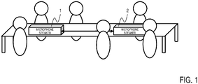
- the voice of a speaking person away from listeners in the same space may be collected by a microphone speaker 1 disposed near the speaking person, and may be amplified and reproduced by a microphone speaker 2 disposed near the listeners.
- the loudspeakers include two microphones and two speakers (for example, two microphone speakers, each incorporating a microphone and a speaker into one housing). Sound collected by one of the two microphones closer to the speaking person is reproduced by one of the two speakers farther from the speaking person.
- a speaking person are not so far from each other unlike in such a case that the voice of a person speaking in an auditorium is amplified.
- the amplified voice is reproduced with a delay, the amplified voice sounds unsynchronized with the direct sound of the speaking person's voice, and this gives a feeling of auditory unnaturalness. For example, if an amplified voice is heard 20 to 30 ms after a direct sound, the human ear recognizes these sounds as an echo and feels them unnatural. Therefore, low-delay processing is required in a system as in Fig. 1 .
- howling occurs that depends on the volume of amplified sounds and the room environment.
- Methods for preventing howling include increasing the distance between a microphone and a speaker and reducing the speaker volume, as well as providing a howling prevention function.
- patent literature 1 describes a method of detecting howling by performing thresholding on the power for each frequency.
- Patent literature 1 Japanese Patent Application Laid-Open No. H6-164278
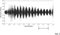
- the system as in Fig. 1 may experience howling as shown in Fig. 2 , in which two close frequencies produce howling, and the temporal waveforms of the howling create beats.
- the howling has not developed so much to diverge.
- large howling components only remain despite the absence of voices, resulting in very uncomfortable sounds similar to typical howling sounds.
- problems will arise if this case is addressed with conventional techniques.
- addressing this case with conventional techniques requires "analyzing the frequencies in a sufficiently long frame for excluding the influence of the beating phenomenon” or “smoothing in the temporal direction for reducing the influence of the beat components on the result of analysis in short time frames” in order to detect the occurrence of howling. Both require observation for a long period, which is against the above-described requirement "low delay” or which allows howling to be addressed only after some howling occurs because detection is delayed.
- An object of the present invention is to provide a howling suppression apparatus, and a method and a program for the same, that enable preventing a delay in howling detection and improving a howling prevention effect of a loudspeaker system.
- a delay in howling detection can be prevented to improve a howling prevention effect of a loudspeaker system.
- Fig. 3 shows an exemplary arrangement of the two howling suppression apparatuses 100-i.
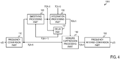
- Fig. 4 shows a functional block diagram of each howling suppression apparatus according to a first embodiment
- Fig. 5 shows a process flow thereof.
- the howling suppression apparatus 100-i includes a frequency conversion part 110, a smoothing processing part 120, a delay part 121, an integration processing part 130, a howling suppression processing part 140, and a frequency reverse-conversion part 150.
- the howling suppression processing part 140 includes a power determination part 141, a time constant determination part 142, a delay part 143, a gain calculation part 144, and a gain superposition part 145.
- Fig. 6 shows a functional block diagram of the howling suppression processing part 140
- Fig. 7 shows a process flow thereof.
- the howling suppression apparatus 100-i suppresses howling components in the sound signal collected by the microphone 80-i of its own channel and outputs the suppressed signal to a speaker 90-i of its own channel.
- the speaker 90-i reproduces the suppressed signal.
- the microphone 80-i and a speaker 90j constitutes one microphone speaker.
- Each howling suppression apparatus is, for example, a special apparatus configured in such a manner that a special program is read into a known or special-purpose computer having a central processing unit (CPU) and main memory (RAM: Random Access Memory).
- the howling suppression apparatus performs, for example, processing under the control of the central processing unit.
- Data input to the howling suppression apparatus and data resulting from the processing are, for example, stored in the main memory and the data stored in the main memory are read as needed into the central processing unit to be used for other processing.
- Each processing part of the howling suppression apparatus may be implemented at least in part in hardware such as an integrated circuit.
- Each storage part in the howling suppression apparatus may be implemented, for example, in the main memory such as RAM (Random Access Memory) or in middleware such as a relational database or a key-value store. Note that each storage part may not necessarily be provided internally to the howling suppression apparatus. Rather, each storage part may be provided externally to the howling suppression apparatus as an auxiliary storage device implemented as a hard disk, an optical disc, or semiconductor memory elements such as flash memory.
- main memory such as RAM (Random Access Memory)
- middleware such as a relational database or a key-value store.
- each storage part may not necessarily be provided internally to the howling suppression apparatus. Rather, each storage part may be provided externally to the howling suppression apparatus as an auxiliary storage device implemented as a hard disk, an optical disc, or semiconductor memory elements such as flash memory.
- the frequency conversion part 110 receives, as an input, a sound signal x i (t) collected by the microphone 80-i of its own channel, converts the signal into a frequency-domain signal (S 110), and outputs the converted signal X i (k,n).
- Fourier transform such as fast Fourier transform
- t denotes the discrete-time index
- Fourier transform is performed for each frame period T/D (D is any integer equal to or greater than 2 and by which T is divisible) using the past T sound signals x i (t), x i (t-1), ..., x i (t-T+1) at time t and the preceding times.
- T/D the discrete-time index
- the signals input to the howling suppression apparatuses 100-i and the frequency conversion parts 110 may not be the sound signals themselves collected by the microphones, but may be signals resulting from processing sound signals.
- sound signals collected by m microphones e.g., a microphone array
- These output signals may be input to the howling suppression apparatuses 100-i and the frequency conversion parts 110 in place of the sound signal x i (t).
- the signals to be input may be subjected to other types of signal processing, such as noise suppression processing, instead of beamforming processing.
- L signals obtained from sound signals collected by microphones may be input to the howling suppression apparatuses 100-i and the frequency conversion parts 110.
- the smoothing processing part 120 receives the signal X i (k,n) as an input, retrieves a value X i '(k,n-1) for the immediately preceding time (frame) from the delay part 121, smoothes the signal X i (k,n) in the temporal direction (S120) to obtain a value X' i (k,n), and outputs the value to the integration processing part 130 and the howling suppression apparatus 100-j.
- the smoothing processing part 120 further stores the value X' i (k,n) in the delay part 121 for use in smoothing processing for the next frame n+1.
- the integration processing part 130 receives, as inputs, the value X' i (k,n), which is the output value of the smoothing processing part 120 of the howling suppression apparatus 100-i, and a value X' j (k,n), which is the output value of the smoothing processing part 120 of the other howling suppression apparatus 100-j.
- the integration processing part 130 obtains the maximum value - X(k,n) between the two values X' i (k,n) and X' j (k,n) (S130) and outputs the maximum value.
- This processing of obtaining the maximum value may also be referred to as the processing of integrating the two values X' i (k,n) and X' j (k,n), and the maximum value - X(k,n) may also be referred to as the integrated value.
- the system utilizes the fact that, if howling occurs in the loop of two microphone speakers, beats are out of phase between the respective microphone input signals. For example, if the maximum phase shift is ⁇ , the howling becomes locally maximum at one microphone input when the howling becomes locally minimum at the other microphone input, and vice versa.
- Fig. 8 shows an enlarged 0.1-second interval from 0.35 to 0.45 seconds in Fig. 2 , in which vertically arranged x 1 and x 2 are plotted. It can be seen from Fig. 8 that the beat peaks do not align in time. Therefore, if the beats are out of phase and their amplitudes are close, the maximum value between the two values can be taken to reduce the influence of the beat amplitudes.
- the howling suppression processing part 140 receives the maximum value - X(k,n) and the frequency-domain signal X i (k,n) as inputs, performs howling suppression processing on the signal X i (k,n) using the maximum value - X(k,n) (S 140), and outputs a suppressed signal Y i (k,n).
- the howling suppression processing part 140 performs the howling suppression processing by multiplying the signal X i (k,n) by the smaller one of a first gain obtained based on the maximum value - X(k,n) and a second gain obtained based on the value indicating the variation in the maximum value - X(k,n). Details of processing in each part of the howling suppression processing part 140 will be described below with reference to Figs. 6 and 7 .
- the above example indicates that the power condition is satisfied if the power determination result P(k,n) is 1.
- the delay part 143 receives the maximum value - X(k,n) as an input, stores the value, and outputs the value at the request of the time constant determination part 142.
- the time constant determination part 142 receives the maximum value - X(k,n) as an input and retrieves the maximum value - X(k,n-1) for the immediately preceding time (frame) from the delay part 143.
- the time constant determination part 142 determines whether the difference value of the maximum value - X(k,n) from the maximum value for the immediately preceding time (frame) satisfies a condition (S 142), and outputs a time constant determination result S(k,n).
- whether the difference value of the maximum value - X(k,n) from the maximum value for the immediately preceding time (frame) satisfies the condition is determined from the magnitude relationship between a value indicating a variation in the maximum value - X(k,n) and a value indicating a predetermined variation.
- the value indicating the variation in the maximum value - X(k,n) is the ratio - X(k,n) / - X(k,n-1) between the maximum value - X(k,n) for the current frame and the maximum value - X(k,n-1) for the past frame.
- the value indicating the predetermined variation is a predetermined time constant ⁇ .
- the time constant determination part 142 determines whether the maximum value - X(k,n) for the current frame is greater than the value ⁇ - X(k,n-1) resulting from multiplying the maximum value - X(k,n-1) for the preceding frame by the time constant ⁇ , and outputs a variation determination result S(k,n).
- the gain calculation part 144 then obtains a first gain G p based on the magnitude relationship between the power index - P(k,n) and a predetermined threshold P thr .
- - P min ⁇ - P max a predetermined threshold
- the first gain G p is obtained as follows.
- G p1 is a fixed value greater than or equal to 0 and less than or equal to 1.
- - S min ⁇ - S max .
- the second gain Gs is obtained as follows.
- G s1 is a fixed value greater than or equal to 0 and less than or equal to 1.
- the gain calculation part 144 sets the smaller one of the first gain G P and the second gain Gs as a third gain G and outputs the third gain G as a gain for suppressing howling.
- the gain superposition part 145 receives the third gain G and the signal X i (k,n) as inputs, multiplies the signal X i (k,n) by the third gain G (S 145), and outputs the product as a suppressed signal Y i (k,n).
- Y i k n X i k n G k n
- the frequency reverse-conversion part 150 receives the signal Y i (k,n) as an input, converts the signal into a time-domain signal (S 150), and outputs the converted signal y i (t) as an output value of the howling suppression apparatus 100-i. Converting into the time domain may use a method corresponding to the method used for converting into the frequency domain used in the frequency conversion part 110.
- y i (n) [y i (nT-T+1), y i (nT-T+2), ..., y i (nT)].
- the time-domain signal y i (n) obtained for each frame with inverse Fourier transform is appropriately shifted to calculate a linear combination, resulting in the continuous time-domain signal y i (t).
- G S 1 ⁇ 2 ⁇ Thr 3 / X ⁇ k n
- ⁇ 2 is a real number greater than or equal to 0 and less than or equal to 1.
- Thr3 is set in the same manner as Thr2.
- the howling suppression system may include L howling suppression apparatuses 100-i (see Fig. 9 ).
- the integration processing part 130 obtains the maximum value - X(k,n) among the L values X' i (k,n) (S130) and outputs the maximum value.
- This processing of obtaining the maximum value may also be referred to as the processing of integrating the L values X' i (k,n), and the maximum value - X(k,n) may also be referred to as the integrated value.
- the howling suppression system in the first embodiment can be expanded into a system that includes L howling suppression apparatuses 100-i.
- the first embodiment could be said to be an example of the second modification.
- L-1 output values y i from the output values y i of the L howling suppression apparatuses 100-i may be combined (mixed) and output to the speaker 90-i.
- the L output values y i minus an output value y i corresponding to the sound signal collected by the microphone of one microphone speaker (L-1 output values y i ) may be combined, and reproduced by the speaker of the same microphone speaker.
- the two howling processing apparatuses 100-i in this embodiment may be embodied as one apparatus.
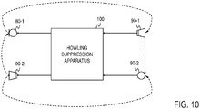
- Fig. 10 shows an exemplary arrangement of a howling suppression apparatus 100 in a third modification.
- Fig. 11 shows a functional block diagram of the howling suppression apparatus according to this modification.
- the howling suppression apparatus 100 includes a frequency conversion part 110, a smoothing processing part 120, a delay part 121, an integration processing part 130, a howling suppression processing part 140, and a frequency reverse-conversion part 150, each of which performs processing similar to the processing in the first embodiment.
- signals of two channels are processed in this modification.
- the integration processing part performs processing as in the first embodiment.
- the howling suppression apparatus 100 receives, as inputs, sound signals collected by the microphones 80-i of the two channels, suppresses howling components in the respective sound signals collected by the two microphones 80-i, and outputs the respective suppressed signals to the two speakers 90-i.
- the first to third modifications may be combined with each other.
- howling components are suppressed in all the L channels.
- howling components may be suppressed in at least one of the L channels.
- only one of the howling suppression processing apparatuses 100-1 and 100-2 may be disposed. Then the frequency conversion part 110 and the smoothing processing part 120 in the disposed howling suppression processing apparatus process the sound signal collected by the microphone of the other channel (S110, S120), thereby generating the input value to the integration processing part 130.
- the time-domain sound signal collected by the microphone is taken as an input.
- a sound signal converted into a frequency-domain signal by a separate apparatus may be taken as an input.
- the howling suppression apparatus 100-i may not include the frequency domain conversion part 110.
- the smoothing processing performed in the smoothing processing part 120 stabilizes the frames. However, even without the smoothing processing, a delay in howling detection can still be prevented to improve the howling prevention effect of the loudspeaker system. Therefore, the howling suppression apparatus 100-i may not include the smoothing processing part 120.
- the integration processing part 130 may receive, as inputs, L i-th signals that are frequency-domain signals obtained from sound signals collected by multiple microphones.
- L i-th signals that are frequency-domain signals obtained from sound signals collected by multiple microphones.
- the integration processing part 130 may receive, as inputs, the frequency-domain signal X i (k,n) before being subjected to the smoothing processing, and frequency-domain signals resulting from performing signal processing such as beamforming processing and noise suppression processing on sound signals collected by multiple microphones.
- the howling suppression apparatus 100-i may, for example, simply output the frequency-domain signal Y i (k,n). An apparatus in a subsequent stage may then perform some signal processing on the frequency-domain signal Y i (k,n) and convert the processed signal into a time-domain signal. Therefore, the howling suppression apparatus 100-i may not include the frequency reverse-conversion part 150.
- this may be affected by other sounds, such as a voice uttered on one side. That is, - X(k,n) takes a large value if either side has large frequency components.
- the smaller one of the values of the two channels is selected.
- the smaller one of the values of the two channels is relatively large in comparison with the case of a normally uttered voice because the sounds of the two channels increase at almost the same volume rate. Using such a value makes it easier to distinguish between howling sounds and other sounds than in the first embodiment.
- Fig. 12 shows a functional block diagram of a howling suppression apparatus according to the second embodiment
- Fig. 13 shows a process flow thereof.
- Each howling suppression apparatus 100-i includes a frequency conversion part 110, a smoothing processing part 120, a delay part 121, an integration processing part 230, a howling determination part 260, a howling suppression processing part 240, and a frequency reverse-conversion part 150. Processing in the frequency conversion part 110, the smoothing processing part 120, and the frequency reverse-conversion part 150 are similar to the processing in the first embodiment.
- two microphones 80-i are disposed at different distances from the sound source.
- the integration processing part 230 receives, as inputs, a value X'i(k,n), which is an output value of the smoothing processing part 120 of the howling suppression apparatus 100-i, and a value X' j (k,n), which is an output value of the smoothing processing part 120 of the other howling suppression apparatus 100-j.
- the integration processing part 230 obtains the minimum value - X(k,n) between the two values X' i (k,n) and X' j (k,n) (S230) and outputs the minimum value.
- This processing of obtaining the minimum value may also be referred to as the processing of integrating the two values X' i (k,n) and X' j (k,n), and the minimum value - X(k,n) may also be referred to as the integrated value.
- the howling determination part 260 receives, as inputs, the value X' i (k,n), which is the output value of the smoothing processing part 120 of the howling suppression apparatus 100-i, and the value X' j (k,n), which is the output value of the smoothing processing part 120 of the other howling suppression apparatus 100-j. If the sign of the difference between the two values X' i (k,n) and X' j (k,n) changes a predetermined number of times or more in a predetermined period, the howling determination part 260 determines that howling is likely to occur or is occurring (S260) and outputs the determination result. For example, if it is determined that howling is likely to occur or is occurring, 1 is output as the determination result; otherwise, 0 is output.
- the sign changes six times in 0.1 seconds.
- the predetermined period and the predetermined number of times may be set so that such a state can be detected.
- the howling suppression processing part 240 receives, as inputs, the minimum value - X(k,n), the frequency-domain signal X i (k,n), and the determination result of the howling determination part 260. If the determination result indicates that howling is likely to occur or is occurring, the howling suppression processing part 240 performs howling suppression processing on the signal X i (k,n) using the minimum value - X(k,n) (S240) and outputs a suppressed signal Y i (k,n).
- the howling determination part 260 may not perform the determination processing once it determines that howling is likely to occur or is occurring. If the determination result does not indicate that howling is likely to occur or is occurring, the howling suppression processing may not be repeated and the howling determination part 260 may resume the determination processing.
- the determination result of the howling determination part 260 may also be input to the integration part 230, and if the determination result does not indicate that howling is likely to occur or is occurring, the integration processing in the integration processing part 230 (S230) may be omitted.
- the program describing the details of the processing may be recorded on a computer-readable recording medium.
- the computer-readable recording medium may be any appropriate medium, for example a magnetic recording device, an optical disc, a magneto-optical recording medium, or semiconductor memory.
- the program may be distributed by, for example, selling, giving, or lending a portable recording medium, such as a DVD or a CD-ROM, having the program recorded thereon.
- the program may further be distributed by storing the program in a storage device in a server computer and transferring the program from the server computer to another computer over a network.
- the computer executing the program once stores, in its storage, the program recorded on a portable recording medium or transferred from a server computer.
- the computer reads the program stored in its storage and performs processing according to the program read.
- the computer may directly read the program from the portable recording medium and perform processing according to the program.
- portions of the program are sequentially transferred from the server computer to the computer, the computer may sequentially perform processing according to the received portions of the program.
- the above processing may also be performed through what is called an ASP (Application Service Provider) service, in which case the server computer does not transfer the program to the computer but the processing functions are implemented only by instructing to execute the program and obtaining the results.
- the program here includes information that is not the program itself but is used for processing in a computer (such as data that does not contain direct instructions to the computer but has a nature of defining processing in the computer).
- apparatuses have been described as configured by executing a predetermined program on a computer, at least part of the processing in the apparatuses may be implemented in hardware.
Landscapes
- Engineering & Computer Science (AREA)
- Signal Processing (AREA)
- Health & Medical Sciences (AREA)
- Physics & Mathematics (AREA)
- Acoustics & Sound (AREA)
- Otolaryngology (AREA)
- General Health & Medical Sciences (AREA)
- Quality & Reliability (AREA)
- Computational Linguistics (AREA)
- Audiology, Speech & Language Pathology (AREA)
- Human Computer Interaction (AREA)
- Multimedia (AREA)
- Circuit For Audible Band Transducer (AREA)
- Domestic Plumbing Installations (AREA)
- Electrotherapy Devices (AREA)
- Application Of Or Painting With Fluid Materials (AREA)
Abstract
Description
- The present invention relates to a technique for suppressing howling that occurs in amplifying voices with a speaker to facilitate conversation.
- In a wide space, a situation may arise in which people have difficulty in conversation because their voices are not sufficiently heard by target persons. In such cases, loudspeakers are often used. When loudspeakers are used in a scene such as a conference with many participants, as shown in
Fig. 1 , the voice of a speaking person away from listeners in the same space may be collected by amicrophone speaker 1 disposed near the speaking person, and may be amplified and reproduced by amicrophone speaker 2 disposed near the listeners. The loudspeakers include two microphones and two speakers (for example, two microphone speakers, each incorporating a microphone and a speaker into one housing). Sound collected by one of the two microphones closer to the speaking person is reproduced by one of the two speakers farther from the speaking person. - In a system as in
Fig. 1 , speaking persons are not so far from each other unlike in such a case that the voice of a person speaking in an auditorium is amplified. This creates a situation in which a speaking person's voice itself (a direct sound) is slightly heard in addition to the amplified voice. If the amplified voice is reproduced with a delay, the amplified voice sounds unsynchronized with the direct sound of the speaking person's voice, and this gives a feeling of auditory unnaturalness. For example, if an amplified voice is heard 20 to 30 ms after a direct sound, the human ear recognizes these sounds as an echo and feels them unnatural. Therefore, low-delay processing is required in a system as inFig. 1 . - In a microphone speaker system as above, generally, howling occurs that depends on the volume of amplified sounds and the room environment. Methods for preventing howling include increasing the distance between a microphone and a speaker and reducing the speaker volume, as well as providing a howling prevention function. For example,
patent literature 1 describes a method of detecting howling by performing thresholding on the power for each frequency. - Patent literature 1: Japanese Patent Application Laid-Open No.
H6-164278 - The system as in
Fig. 1 may experience howling as shown inFig. 2 , in which two close frequencies produce howling, and the temporal waveforms of the howling create beats. InFig. 2 , the howling has not developed so much to diverge. However, particularly around 0.4 seconds, large howling components only remain despite the absence of voices, resulting in very uncomfortable sounds similar to typical howling sounds. Unfortunately, problems will arise if this case is addressed with conventional techniques. Specifically, addressing this case with conventional techniques requires "analyzing the frequencies in a sufficiently long frame for excluding the influence of the beating phenomenon" or "smoothing in the temporal direction for reducing the influence of the beat components on the result of analysis in short time frames" in order to detect the occurrence of howling. Both require observation for a long period, which is against the above-described requirement "low delay" or which allows howling to be addressed only after some howling occurs because detection is delayed. - An object of the present invention is to provide a howling suppression apparatus, and a method and a program for the same, that enable preventing a delay in howling detection and improving a howling prevention effect of a loudspeaker system.
- For solving the above problems, according to an aspect of the present invention, a howling suppression apparatus comprises: an integration processing part that obtains a maximum value among L values corresponding to n-th frames of L i-th signals, for i = 1, 2, ..., L, L being any integer equal to or greater than 2, the L i-th signals being frequency-domain signals obtained from sound signals collected by a plurality of microphones; and a howling suppression processing part that performs howling suppression processing on at least any of the L i-th signals using the maximum value.
- For solving the above problems, according to another aspect of the present invention, a howling suppression apparatus comprises: an integration processing part that obtains a minimum value among L values corresponding to n-th frames of L i-th signals, for i = 1, 2, ..., L, L being any integer equal to or greater than 2, the L i-th signals being frequency-domain signals obtained from sound signals collected by a plurality of microphones; a howling determination part that determines that howling is likely to occur or is occurring if a sign of a difference between two values corresponding to n-th frames of two of the i-th signals changes a predetermined number of times or more in a predetermined period, the two of the i-th signals being sound signals collected by two of L microphones and converted into frequency-domain signals; and a howling suppression processing part that performs howling suppression processing on at least any of the L i-th signals using the minimum value if it is determined that howling is likely to occur or is occurring.
- For solving the above problems, according to a further aspect of the present invention, a method for suppressing howling comprises: an integration processing step of obtaining a maximum value among L values corresponding to n-th frames of L i-th signals, for i = 1, 2, ..., L, L being any integer equal to or greater than 2, the L i-th signals being frequency-domain signals obtained from sound signals collected by a plurality of microphones; and a howling suppression processing step of performing howling suppression processing on at least any of the L i-th signals using the maximum value.
- For solving the above problems, according to a still further aspect of the present invention, a method for suppressing howling comprises: an integration processing step of obtaining a minimum value among L values corresponding to n-th frames of L i-th signals, for i = 1, 2, ..., L, L being any integer equal to or greater than 2, the L i-th signals being frequency-domain signals obtained from sound signals collected by a plurality of microphones; a howling determination step of determining that howling is likely to occur or is occurring if a sign of a difference between two values corresponding to n-th frames of two of the i-th signals changes a predetermined number of times or more in a predetermined period, the two of the i-th signals being sound signals collected by two of L microphones and converted into frequency-domain signals; and a howling suppression processing step of performing howling suppression processing on at least any of the L i-th signals using the minimum value if it is determined that howling is likely to occur or is occurring.
- According to the present invention, a delay in howling detection can be prevented to improve a howling prevention effect of a loudspeaker system.
-
-
Fig. 1 is a diagram for describing a situation in which loudspeakers are used; -
Fig. 2 is a diagram for describing a howling state; -
Fig. 3 is a diagram showing an exemplary arrangement of two howling suppression apparatuses; -
Fig. 4 is a functional block diagram of a howling suppression apparatus according to a first embodiment; -
Fig. 5 is a diagram showing an exemplary process flow of the howling suppression apparatus according to the first embodiment; -
Fig. 6 is a functional block diagram of a howling suppression processing part; -
Fig. 7 is a diagram showing an exemplary process flow of the howling suppression processing part; -
Fig. 8 is a diagram of an enlarged 0.1-second interval from 0.35 to 0.45 seconds inFig. 2 , in which vertically arranged x1 and x2 are plotted; -
Fig. 9 is a diagram showing an exemplary arrangement of L howling suppression apparatuses in a second modification of the first embodiment; -
Fig. 10 is a diagram showing an exemplary arrangement of a howling suppression apparatus in a third modification of the first embodiment; -
Fig. 11 is a functional block diagram of the howling suppression apparatus according to the third modification of the first embodiment; -
Fig. 12 is a functional block diagram of a howling suppression apparatus according to a second embodiment; and -
Fig. 13 is a diagram showing an exemplary process flow of the howling suppression apparatus according to the second embodiment. - Embodiments of the present invention will be described below. In the drawings referred to in the following description, components having like functions and steps representing like processing are labeled with like symbols, and redundant description of such components and steps will not be given. In the following description, symbols such as "-" used in the text are originally to be shown above the characters that follow the symbols but are shown immediately before the characters because of limitations in text notation. In formulae, these symbols are shown at the original positions. Processing performed on an element basis for a vector or matrix are intended to apply to all the elements of the vector or matrix unless otherwise specified.
- Signal analysis values of two howling suppression channels are associated with each other to obtain more accurate information about components that may constitute howling frequencies. This prevents howling from diverging due to delayed detection.
- A howling suppression system includes two howling suppression apparatuses 100-i, for i = 1, 2.
Fig. 3 shows an exemplary arrangement of the two howling suppression apparatuses 100-i. -
Fig. 4 shows a functional block diagram of each howling suppression apparatus according to a first embodiment, andFig. 5 shows a process flow thereof. - The howling suppression apparatus 100-i includes a
frequency conversion part 110, asmoothing processing part 120, adelay part 121, anintegration processing part 130, a howlingsuppression processing part 140, and a frequency reverse-conversion part 150. - The howling
suppression processing part 140 includes apower determination part 141, a timeconstant determination part 142, adelay part 143, again calculation part 144, and again superposition part 145.Fig. 6 shows a functional block diagram of the howlingsuppression processing part 140, andFig. 7 shows a process flow thereof. - As shown in
Fig. 3 , each howling suppression apparatus 100-i receives, as inputs, a sound signal collected by a microphone 80-i of its own channel and an output value of thesmoothing processing part 120 of the howling suppression apparatus 100-j of the other channel, for j = 1, 2, and i # j. The howling suppression apparatus 100-i suppresses howling components in the sound signal collected by the microphone 80-i of its own channel and outputs the suppressed signal to a speaker 90-i of its own channel. The speaker 90-i reproduces the suppressed signal. For example, the microphone 80-i and a speaker 90j constitutes one microphone speaker. - Each howling suppression apparatus is, for example, a special apparatus configured in such a manner that a special program is read into a known or special-purpose computer having a central processing unit (CPU) and main memory (RAM: Random Access Memory). The howling suppression apparatus performs, for example, processing under the control of the central processing unit. Data input to the howling suppression apparatus and data resulting from the processing are, for example, stored in the main memory and the data stored in the main memory are read as needed into the central processing unit to be used for other processing. Each processing part of the howling suppression apparatus may be implemented at least in part in hardware such as an integrated circuit. Each storage part in the howling suppression apparatus may be implemented, for example, in the main memory such as RAM (Random Access Memory) or in middleware such as a relational database or a key-value store. Note that each storage part may not necessarily be provided internally to the howling suppression apparatus. Rather, each storage part may be provided externally to the howling suppression apparatus as an auxiliary storage device implemented as a hard disk, an optical disc, or semiconductor memory elements such as flash memory.
- Each part will be described below.
- The
frequency conversion part 110 receives, as an input, a sound signal xi(t) collected by the microphone 80-i of its own channel, converts the signal into a frequency-domain signal (S 110), and outputs the converted signal Xi(k,n). For example, the time-domain sound signal xi(t) is converted into the frequency-domain signal with Fourier transform (such as fast Fourier transform) as expressed by the following formula:
- The signals input to the howling suppression apparatuses 100-i and the
frequency conversion parts 110 may not be the sound signals themselves collected by the microphones, but may be signals resulting from processing sound signals. For example, sound signals collected by m microphones (e.g., a microphone array) may be subjected to beamforming processing to obtain L (in this embodiment, L = 2) output signals each having a predetermined directionality. These output signals may be input to the howling suppression apparatuses 100-i and thefrequency conversion parts 110 in place of the sound signal xi(t). The signals to be input may be subjected to other types of signal processing, such as noise suppression processing, instead of beamforming processing. In essence, L signals obtained from sound signals collected by microphones may be input to the howling suppression apparatuses 100-i and thefrequency conversion parts 110. - The smoothing
processing part 120 receives the signal Xi(k,n) as an input, retrieves a value Xi'(k,n-1) for the immediately preceding time (frame) from thedelay part 121, smoothes the signal Xi(k,n) in the temporal direction (S120) to obtain a value X'i(k,n), and outputs the value to theintegration processing part 130 and the howling suppression apparatus 100-j. The smoothingprocessing part 120 further stores the value X'i(k,n) in thedelay part 121 for use in smoothing processing for the nextframe n+ 1. For example, each frequency component is smoothed in the temporal direction by calculating a weighted sum of the frequency component and the value Xi'(k,n-1) for the immediately preceding time (frame) with the following formula:
- The
integration processing part 130 receives, as inputs, the value X'i(k,n), which is the output value of the smoothingprocessing part 120 of the howling suppression apparatus 100-i, and a value X'j(k,n), which is the output value of the smoothingprocessing part 120 of the other howling suppression apparatus 100-j. Theintegration processing part 130 obtains the maximum value -X(k,n) between the two values X'i(k,n) and X'j(k,n) (S130) and outputs the maximum value. This processing of obtaining the maximum value may also be referred to as the processing of integrating the two values X'i(k,n) and X'j(k,n), and the maximum value -X(k,n) may also be referred to as the integrated value. For example, the maximum value is obtained with the following formula:
- With this configuration, the system utilizes the fact that, if howling occurs in the loop of two microphone speakers, beats are out of phase between the respective microphone input signals. For example, if the maximum phase shift is π, the howling becomes locally maximum at one microphone input when the howling becomes locally minimum at the other microphone input, and vice versa.
Fig. 8 shows an enlarged 0.1-second interval from 0.35 to 0.45 seconds inFig. 2 , in which vertically arranged x1 and x2 are plotted. It can be seen fromFig. 8 that the beat peaks do not align in time. Therefore, if the beats are out of phase and their amplitudes are close, the maximum value between the two values can be taken to reduce the influence of the beat amplitudes. - The howling
suppression processing part 140 receives the maximum value -X(k,n) and the frequency-domain signal Xi(k,n) as inputs, performs howling suppression processing on the signal Xi(k,n) using the maximum value -X(k,n) (S 140), and outputs a suppressed signal Yi(k,n). Using the maximum value -X(k,n) corresponds to utilizing the fact that howling components are out of phase among sound signals collected by L (in this embodiment, L = 2) microphones. That is, it can be said that the howlingsuppression processing part 140 performs the howling suppression processing by utilizing the fact that howling components are out of phase among sound signals collected by L microphones. - In this embodiment, at least either (i) if the maximum value - X(k,n) is greater than a value indicating predetermined power or (ii) if a value indicating a variation in the maximum value -X(k,n) is greater than a value indicating a predetermined variation, the howling
suppression processing part 140 performs the howling suppression processing by multiplying the signal Xi(k,n) by the smaller one of a first gain obtained based on the maximum value -X(k,n) and a second gain obtained based on the value indicating the variation in the maximum value -X(k,n). Details of processing in each part of the howlingsuppression processing part 140 will be described below with reference toFigs. 6 and7 . - The
power determination part 141 receives the maximum value - X(k,n) as an input and determines whether the maximum value -X(k,n) satisfies a power condition. For example, thepower determination part 141 determines whether the maximum value -X(k,n) is greater than a value indicating predetermined power (a threshold Thr1, which is a positive real number precalculated on the basis of, e.g., experiments) (S141) and outputs a power determination result P(k,n). For example, the power determination result P(k,n) is obtained with the following formula.
- Thus, the above example indicates that the power condition is satisfied if the power determination result P(k,n) is 1.
- The
delay part 143 receives the maximum value -X(k,n) as an input, stores the value, and outputs the value at the request of the timeconstant determination part 142. - The time
constant determination part 142 receives the maximum value -X(k,n) as an input and retrieves the maximum value -X(k,n-1) for the immediately preceding time (frame) from thedelay part 143. The timeconstant determination part 142 determines whether the difference value of the maximum value -X(k,n) from the maximum value for the immediately preceding time (frame) satisfies a condition (S 142), and outputs a time constant determination result S(k,n). - In this embodiment, whether the difference value of the maximum value -X(k,n) from the maximum value for the immediately preceding time (frame) satisfies the condition is determined from the magnitude relationship between a value indicating a variation in the maximum value -X(k,n) and a value indicating a predetermined variation. The value indicating the variation in the maximum value -X(k,n) is the ratio -X(k,n) / -X(k,n-1) between the maximum value -X(k,n) for the current frame and the maximum value -X(k,n-1) for the past frame. The value indicating the predetermined variation is a predetermined time constant β. The time
constant determination part 142 determines whether the maximum value -X(k,n) for the current frame is greater than the value β-X(k,n-1) resulting from multiplying the maximum value -X(k,n-1) for the preceding frame by the time constant β, and outputs a variation determination result S(k,n). For example, the variation determination result S(k,n) is obtained with the following formula.
- The time constant β is typically a value sufficiently greater than reverberations in the room and less than 1 (= no attenuation). Thus, the above example indicates that the variation condition is satisfied if the variation determination result S(k,n) is 1.
- The
gain calculation part 144 receives the power determination result P(k,n) and the variation determination result S(k,n) as inputs, calculates a gain for suppressing howling (S144), and outputs the gain. For example, if a power index -P(k,n) obtained from the power determination result P(k,n) for the current frame is smaller than a predetermined value -Pmin, thegain calculation part 144 sets -P(k,n) = -Pmin. If the power index -P(k,n) is greater than a predetermined value -Pmax, thegain calculation part 144 sets -P(k,n) = - Pmax. Thegain calculation part 144 then obtains a first gain Gp based on the magnitude relationship between the power index -P(k,n) and a predetermined threshold Pthr. Here, -Pmin < -Pmax. For example, the first gain Gp is obtained as follows.
- Gp1 is a fixed value greater than or equal to 0 and less than or equal to 1. The initial value of -P(k,n) for n = 0 is 0.
- Further, if a time constant index -S(k,n) obtained from the variation determination result S(k,n) for the current frame is smaller than a predetermined value -Smin, the
gain calculation part 144 sets -S(k,n) = -Smin. If the time constant index -S(k,n) is greater than a predetermined value -Smax, thegain calculation part 144 sets -S(k,n) = -Smax. Thegain calculation part 144 then obtains a second gain Gs based on the magnitude relationship between the time constant index -S(k,n) and a predetermined threshold Sthr. Here, -Smin < -Smax. For example, the second gain Gs is obtained as follows.
- Gs1 is a fixed value greater than or equal to 0 and less than or equal to 1. The initial value of -S(k,n) for n = 0 is 0.
- The
gain calculation part 144 sets the smaller one of the first gain GP and the second gain Gs as a third gain G and outputs the third gain G as a gain for suppressing howling. For example, the third gain G is obtained as follows:
- The gain superposition
part 145 receives the third gain G and the signal Xi(k,n) as inputs, multiplies the signal Xi(k,n) by the third gain G (S 145), and outputs the product as a suppressed signal Yi(k,n).
- The frequency reverse-
conversion part 150 receives the signal Yi(k,n) as an input, converts the signal into a time-domain signal (S 150), and outputs the converted signal yi(t) as an output value of the howling suppression apparatus 100-i. Converting into the time domain may use a method corresponding to the method used for converting into the frequency domain used in thefrequency conversion part 110. For example, the frequency-domain signal Yi(k,n) is converted into the time-domain signal with inverse Fourier transform (such as inverse fast Fourier transform):
- With the above configuration, a delay in howling detection can be prevented to improve the howling prevention effect of the loudspeaker system.
- By disposing the two howling suppression apparatuses 100-i as in
Fig. 3 and performing the howling suppression processing in each of the apparatuses for i =1, 2, the occurrence of howling from the two channels can be suppressed. - Although the first gain Gp1 and the second gain Gs1 are fixed values in this embodiment, they may be varied with the input sound signal. For example, the following formula is set.

- α is a real number greater than or equal to 0 and less than or equal to 1. If Xi(k,n) = -X(k,n) and if α = 1, Gp1 is a suppression gain that reduces Xi(k,n) to Thr2. If α is less than 1, an amount of suppression is set that reduces Xi(k,n) to be further smaller than Thr2. For example, Thr2 is set to a value such that any sound greater than or equal to that value is regarded as howling, or to a value less than that value. Thr2 may also be set to a value less than or equal to Thr1 used in the
power determination part 141. - Similarly, for the second gain Gs1, the following formula may be set.

- α2 is a real number greater than or equal to 0 and less than or equal to 1. Thr3 is set in the same manner as Thr2.
- The howling suppression system may include L howling suppression apparatuses 100-i (see
Fig. 9 ). L is any integer equal to or greater than 2, and i = 1, 2, ..., L. - In this second modification, the
integration processing part 130 receives, as inputs, a value X'i(k,n), which is an output value of the smoothingprocessing part 120 of the howling suppression apparatus 100-i, and values X'j(k,n), which are output values of the smoothingprocessing parts 120 of the other L-1 howling suppression apparatuses 100-j, for j = 1, 2, ..., L, and i ≠ j. Theintegration processing part 130 obtains the maximum value -X(k,n) among the L values X'i(k,n) (S130) and outputs the maximum value. This processing of obtaining the maximum value may also be referred to as the processing of integrating the L values X'i(k,n), and the maximum value - X(k,n) may also be referred to as the integrated value. For example, the maximum value is obtained with the following formula:
- With this configuration, the howling suppression system in the first embodiment can be expanded into a system that includes L howling suppression apparatuses 100-i. The first embodiment could be said to be an example of the second modification.
- In an exemplary configuration, L-1 output values yi from the output values yi of the L howling suppression apparatuses 100-i may be combined (mixed) and output to the speaker 90-i. For example, the L output values yi minus an output value yi corresponding to the sound signal collected by the microphone of one microphone speaker (L-1 output values yi) may be combined, and reproduced by the speaker of the same microphone speaker.
- The two howling processing apparatuses 100-i in this embodiment may be embodied as one apparatus.
Fig. 10 shows an exemplary arrangement of a howlingsuppression apparatus 100 in a third modification.Fig. 11 shows a functional block diagram of the howling suppression apparatus according to this modification. The howlingsuppression apparatus 100 includes afrequency conversion part 110, a smoothingprocessing part 120, adelay part 121, anintegration processing part 130, a howlingsuppression processing part 140, and a frequency reverse-conversion part 150, each of which performs processing similar to the processing in the first embodiment. However, in contrast to the first embodiment in which a signal of one channel is processed in each part except the integration processing part, signals of two channels are processed in this modification. The integration processing part performs processing as in the first embodiment. - With this configuration, as shown in
Fig. 10 , the howlingsuppression apparatus 100 receives, as inputs, sound signals collected by the microphones 80-i of the two channels, suppresses howling components in the respective sound signals collected by the two microphones 80-i, and outputs the respective suppressed signals to the two speakers 90-i. - The first to third modifications may be combined with each other.
- In this embodiment and its modifications, howling components are suppressed in all the L channels. Alternatively, howling components may be suppressed in at least one of the L channels. For example, in the first embodiment, only one of the howling suppression processing apparatuses 100-1 and 100-2 may be disposed. Then the
frequency conversion part 110 and the smoothingprocessing part 120 in the disposed howling suppression processing apparatus process the sound signal collected by the microphone of the other channel (S110, S120), thereby generating the input value to theintegration processing part 130. - Although the howling prevention effect according to this configuration is lower than that of the first embodiment, a delay in howling detection can still be prevented to improve the howling prevention effect of the loudspeaker system.
- In this embodiment, the time-domain sound signal collected by the microphone is taken as an input. Alternatively, a sound signal converted into a frequency-domain signal by a separate apparatus may be taken as an input. In this case, the howling suppression apparatus 100-i may not include the frequency
domain conversion part 110. - The smoothing processing performed in the smoothing
processing part 120 stabilizes the frames. However, even without the smoothing processing, a delay in howling detection can still be prevented to improve the howling prevention effect of the loudspeaker system. Therefore, the howling suppression apparatus 100-i may not include the smoothingprocessing part 120. - The
integration processing part 130 may receive, as inputs, L i-th signals that are frequency-domain signals obtained from sound signals collected by multiple microphones. For example, in addition to the two values X'i(k,n) and X'j(k,n) in this embodiment, theintegration processing part 130 may receive, as inputs, the frequency-domain signal Xi(k,n) before being subjected to the smoothing processing, and frequency-domain signals resulting from performing signal processing such as beamforming processing and noise suppression processing on sound signals collected by multiple microphones. - The howling suppression apparatus 100-i may, for example, simply output the frequency-domain signal Yi(k,n). An apparatus in a subsequent stage may then perform some signal processing on the frequency-domain signal Yi(k,n) and convert the processed signal into a time-domain signal. Therefore, the howling suppression apparatus 100-i may not include the frequency reverse-
conversion part 150. - In the
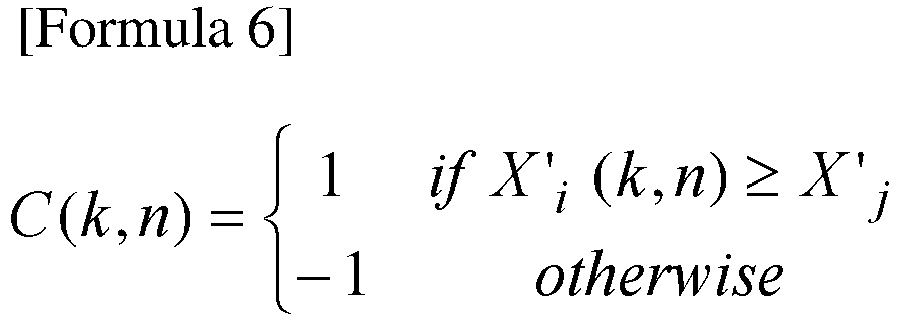
integration processing part 130 in the first embodiment, the influence of beats can be reduced with -X(k,n) = max{Xi'(k,n), Xj'(k,n)}. However, this may be affected by other sounds, such as a voice uttered on one side. That is, -X(k,n) takes a large value if either side has large frequency components. - To address this, an approach is proposed that utilizes the fact that "a voice uttered on one side" has a high sound pressure only on that side, and sets the formula:

- According to the above, if a voice is normally uttered (in other words, if a speaking person utters a voice while no howling is occurring), the smaller one of the values of the two channels is selected. By contrast, if some howling is occurring, the smaller one of the values of the two channels is relatively large in comparison with the case of a normally uttered voice because the sounds of the two channels increase at almost the same volume rate. Using such a value makes it easier to distinguish between howling sounds and other sounds than in the first embodiment.
- The above approach conversely makes it difficult to identify a beat phenomenon, but this problem is mitigated by defining a variable as follows.

- If the sign of this variable frequently switches between positive and negative in a short period, beating is identified.
- In a second embodiment, a configuration for implementing the above approach will be described.
- What are different from the first embodiment will mainly be described.
-
Fig. 12 shows a functional block diagram of a howling suppression apparatus according to the second embodiment, andFig. 13 shows a process flow thereof. - Each howling suppression apparatus 100-i includes a
frequency conversion part 110, a smoothingprocessing part 120, adelay part 121, anintegration processing part 230, a howlingdetermination part 260, a howlingsuppression processing part 240, and a frequency reverse-conversion part 150. Processing in thefrequency conversion part 110, the smoothingprocessing part 120, and the frequency reverse-conversion part 150 are similar to the processing in the first embodiment. - In order to utilize the fact that "a voice uttered on one side" has a high sound pressure only on that side, two microphones 80-i are disposed at different distances from the sound source.
- The
integration processing part 230 receives, as inputs, a value X'i(k,n), which is an output value of the smoothingprocessing part 120 of the howling suppression apparatus 100-i, and a value X'j(k,n), which is an output value of the smoothingprocessing part 120 of the other howling suppression apparatus 100-j. Theintegration processing part 230 obtains the minimum value -X(k,n) between the two values X'i(k,n) and X'j(k,n) (S230) and outputs the minimum value. This processing of obtaining the minimum value may also be referred to as the processing of integrating the two values X'i(k,n) and X'j(k,n), and the minimum value -X(k,n) may also be referred to as the integrated value. For example, the minimum value is obtained with the following formula.
- The howling
determination part 260 receives, as inputs, the value X'i(k,n), which is the output value of the smoothingprocessing part 120 of the howling suppression apparatus 100-i, and the value X'j(k,n), which is the output value of the smoothingprocessing part 120 of the other howling suppression apparatus 100-j. If the sign of the difference between the two values X'i(k,n) and X'j(k,n) changes a predetermined number of times or more in a predetermined period, the howlingdetermination part 260 determines that howling is likely to occur or is occurring (S260) and outputs the determination result. For example, if it is determined that howling is likely to occur or is occurring, 1 is output as the determination result; otherwise, 0 is output. - Whether the sign of the difference between the two values X'i(k,n) and X'j(k,n) changes may be determined using the sign of (X'i(k,n) - X'j(k,n)), or may be determined using the sign of the variable defined as described above:
- For example, in the example of
Fig. 8 , the sign changes six times in 0.1 seconds. The predetermined period and the predetermined number of times may be set so that such a state can be detected. - The howling
suppression processing part 240 receives, as inputs, the minimum value -X(k,n), the frequency-domain signal Xi(k,n), and the determination result of the howlingdetermination part 260. If the determination result indicates that howling is likely to occur or is occurring, the howlingsuppression processing part 240 performs howling suppression processing on the signal Xi(k,n) using the minimum value -X(k,n) (S240) and outputs a suppressed signal Yi(k,n). If the above-described condition is not satisfied (if the determination result does not indicate that howling is likely to occur or is occurring), the howlingsuppression processing part 240 does not perform howling suppression processing on the signal Xi(k,n) and outputs the signal Yi(k,n) = Xi(k,n). If the howling suppression processing is to be performed, processing similar to the processing in the howlingsuppression processing part 140 may be performed using the minimum value -X(k,n) instead of the maximum value -X(k,n). Note that values such as the threshold Thr1 and the time constant β need to be appropriately set for the minimum value -X(k,n). In this embodiment, the howling suppression processing is continuously performed once it is performed. Accordingly, the howlingdetermination part 260 may not perform the determination processing once it determines that howling is likely to occur or is occurring. If the determination result does not indicate that howling is likely to occur or is occurring, the howling suppression processing may not be repeated and the howlingdetermination part 260 may resume the determination processing. - With the above configuration, advantageous effects as in the first embodiment can be achieved. Further, howling can be appropriately suppressed even if sounds other than howling sounds are being produced. This embodiment may be combined with the modifications of the first embodiment. The determination result of the howling
determination part 260 may also be input to theintegration part 230, and if the determination result does not indicate that howling is likely to occur or is occurring, the integration processing in the integration processing part 230 (S230) may be omitted. - The present invention is not limited to the above-described embodiments and modifications. For example, the above-described process steps may be performed sequentially as described, as well as in parallel or in separate processes according to the processing capability of the processing apparatus or according to the necessity. Other changes may be made as appropriate without departing from the spirit of the present invention.
- The various processing functions in each of the apparatuses described in the above embodiments and modifications may be implemented by a computer. In this case, details of the processing of the functions to be provided in the apparatus are written as a program. The program is executed by the computer to cause the various processing functions in each of the above apparatuses to be implemented on the computer.
- The program describing the details of the processing may be recorded on a computer-readable recording medium. The computer-readable recording medium may be any appropriate medium, for example a magnetic recording device, an optical disc, a magneto-optical recording medium, or semiconductor memory.
- The program may be distributed by, for example, selling, giving, or lending a portable recording medium, such as a DVD or a CD-ROM, having the program recorded thereon. The program may further be distributed by storing the program in a storage device in a server computer and transferring the program from the server computer to another computer over a network.
- First, the computer executing the program once stores, in its storage, the program recorded on a portable recording medium or transferred from a server computer. When performing processing, the computer reads the program stored in its storage and performs processing according to the program read. As another embodiment of the program, the computer may directly read the program from the portable recording medium and perform processing according to the program. Further, as portions of the program are sequentially transferred from the server computer to the computer, the computer may sequentially perform processing according to the received portions of the program. The above processing may also be performed through what is called an ASP (Application Service Provider) service, in which case the server computer does not transfer the program to the computer but the processing functions are implemented only by instructing to execute the program and obtaining the results. The program here includes information that is not the program itself but is used for processing in a computer (such as data that does not contain direct instructions to the computer but has a nature of defining processing in the computer).
- Although the apparatuses have been described as configured by executing a predetermined program on a computer, at least part of the processing in the apparatuses may be implemented in hardware.
Claims (9)
- A howling suppression apparatus comprising:an integration processing part that obtains a maximum value among L values corresponding to n-th frames of L i-th signals, for i = 1, 2, ..., L, L being any integer equal to or greater than 2, the L i-th signals being frequency-domain signals obtained from sound signals collected by a plurality of microphones; anda howling suppression processing part that performs howling suppression processing on at least any of the L i-th signals using the maximum value.
- The howling suppression apparatus according to claim 1, wherein the howling suppression processing part performs the howling suppression processing by utilizing a fact that howling components are out of phase among the sound signals collected by the plurality of microphones.
- The howling suppression apparatus according to claim 1 or 2, wherein, at least either (i) if the maximum value is greater than a value indicating predetermined power or (ii) if a value indicating a variation in the maximum value is greater than a value indicating a predetermined variation, the howling suppression processing part performs the howling suppression processing by multiplying at least any of the L i-th signals by a smaller one of a first gain obtained based on the maximum value and a second gain obtained based on the value indicating the variation in the maximum value.
- The howling suppression apparatus according to any of claims 1 to 3, comprising a smoothing processing part that obtains the L values by smoothing the L i-th signals in a temporal direction, wherein
the howling suppression processing part comprises:a power determination part that obtains a power determination result P(k,n) indicating whether the maximum value is greater than a value indicating predetermined power;a time constant determination part that obtains a variation determination result S(k,n) indicating whether the maximum value for a current frame is greater than the maximum value for a past frame multiplied by a predetermined time constant, a value indicating a variation in the maximum value being a ratio between the maximum value for the current frame and the maximum value for the past frame, a value indicating a predetermined variation being the predetermined time constant;a gain calculation part that determines a first gain based on a magnitude relationship between a power index -P(k,n) and a predetermined threshold Pthr by setting -P(k,n) = "Pmin if the power index -P(k,n) obtained from the power determination result P(k,n) for the current frame is smaller than a predetermined value -Pmin and by setting -P(k,n) = -Pmax if the power index -P(k,n) is greater than a predetermined value -Pmax, and determines a second gain based on a magnitude relationship between a time constant index -S(k,n) and a predetermined threshold Sthr by setting -S(k,n) = -Smin if the time constant index -S(k,n) obtained from the variation determination result S(k,n) for the current frame is smaller than a predetermined value -Smin and by setting -S(k,n) = -Smax if the time constant index -S(k,n) is greater than a predetermined value -Smax; anda gain superposition part that multiplies the L i-th signals by a smaller one of the first gain and the second gain. - A howling suppression apparatus comprising:an integration processing part that obtains a minimum value among L values corresponding to n-th frames of L i-th signals, for i = 1, 2, ..., L, L being any integer equal to or greater than 2, the L i-th signals being frequency-domain signals obtained from sound signals collected by a plurality of microphones;a howling determination part that determines that howling is likely to occur or is occurring if a sign of a difference between two values corresponding to n-th frames of two of the i-th signals changes a predetermined number of times or more in a predetermined period, the two of the i-th signals being sound signals collected by two of L microphones and converted into frequency-domain signals; anda howling suppression processing part that performs howling suppression processing on at least any of the L i-th signals using the minimum value if it is determined that howling is likely to occur or is occurring.
- The howling suppression apparatus according to any of claims 1 to 5, wherein L = 2.
- A method for suppressing howling, comprising:an integration processing step of obtaining a maximum value among L values corresponding to n-th frames of L i-th signals, for i = 1, 2, ..., L, L being any integer equal to or greater than 2, the L i-th signals being frequency-domain signals obtained from sound signals collected by a plurality of microphones; anda howling suppression processing step of performing howling suppression processing on at least any of the L i-th signals using the maximum value.
- A method for suppressing howling, comprising:an integration processing step of obtaining a minimum value among L values corresponding to n-th frames of L i-th signals, for i = 1, 2, ..., L, L being any integer equal to or greater than 2, the L i-th signals being frequency-domain signals obtained from sound signals collected by a plurality of microphones;a howling determination step of determining that howling is likely to occur or is occurring if a sign of a difference between two values corresponding to n-th frames of two of the i-th signals changes a predetermined number of times or more in a predetermined period, the two of the i-th signals being sound signals collected by two of L microphones and converted into frequency-domain signals; anda howling suppression processing step of performing howling suppression processing on at least any of the L i-th signals using the minimum value if it is determined that howling is likely to occur or is occurring.
- A program for causing a computer to function as the howling suppression apparatus according to any of claims 1 to 6.
Applications Claiming Priority (2)
| Application Number | Priority Date | Filing Date | Title |
|---|---|---|---|
| JP2018026181 | 2018-02-16 | ||
| PCT/JP2019/005241 WO2019160006A1 (en) | 2018-02-16 | 2019-02-14 | Howling suppression device, method therefor, and program |
Publications (3)
| Publication Number | Publication Date |
|---|---|
| EP3755005A1 true EP3755005A1 (en) | 2020-12-23 |
| EP3755005A4 EP3755005A4 (en) | 2021-10-13 |
| EP3755005B1 EP3755005B1 (en) | 2023-06-07 |
Family
ID=67618652
Family Applications (1)
| Application Number | Title | Priority Date | Filing Date |
|---|---|---|---|
| EP19754765.6A Active EP3755005B1 (en) | 2018-02-16 | 2019-02-14 | Howling suppression device, method therefor, and program |
Country Status (6)
| Country | Link |
|---|---|
| US (1) | US11252506B2 (en) |
| EP (1) | EP3755005B1 (en) |
| JP (1) | JP7028307B2 (en) |
| CN (1) | CN111801951B (en) |
| ES (1) | ES2948633T3 (en) |
| WO (1) | WO2019160006A1 (en) |
Cited By (1)
| Publication number | Priority date | Publication date | Assignee | Title |
|---|---|---|---|---|
| GB2590346A (en) * | 2019-10-10 | 2021-06-30 | Gibby Adrian | Elimination of feedback or howlround due to microphones, pickups and audio input transducers feeding back through loudspeakers |
Families Citing this family (3)
| Publication number | Priority date | Publication date | Assignee | Title |
|---|---|---|---|---|
| CN113450819B (en) * | 2021-05-21 | 2024-06-18 | 音科思(深圳)技术有限公司 | Signal processing method and related product |
| TWI825471B (en) * | 2021-09-01 | 2023-12-11 | 宏碁股份有限公司 | Conference terminal and feedback suppression method |
| JP7725435B2 (en) * | 2022-09-16 | 2025-08-19 | Kddi株式会社 | Communication System |
Family Cites Families (11)
| Publication number | Priority date | Publication date | Assignee | Title |
|---|---|---|---|---|
| JPS63294019A (en) * | 1987-05-27 | 1988-11-30 | Oki Electric Ind Co Ltd | Howling suppression device |
| JP3134557B2 (en) | 1992-11-25 | 2001-02-13 | 松下電器産業株式会社 | Howling suppression device |
| JP4681163B2 (en) * | 2001-07-16 | 2011-05-11 | パナソニック株式会社 | Howling detection and suppression device, acoustic device including the same, and howling detection and suppression method |
| CN1951147B (en) * | 2004-06-16 | 2011-08-17 | 松下电器产业株式会社 | Howling detection device and method |
| EP1965603B1 (en) * | 2005-12-19 | 2017-01-11 | Yamaha Corporation | Sound emission and collection device |
| JP5278219B2 (en) | 2009-07-17 | 2013-09-04 | ヤマハ株式会社 | Howling canceller |
| JP5519689B2 (en) * | 2009-10-21 | 2014-06-11 | パナソニック株式会社 | Sound processing apparatus, sound processing method, and hearing aid |
| JP2013236272A (en) * | 2012-05-09 | 2013-11-21 | Sony Corp | Voice processing device and voice processing method and program |
| EP2736271B1 (en) * | 2012-11-27 | 2019-06-19 | Oticon A/s | A method of controlling an update algorithm of an adaptive feedback estimation system and a de-correlation unit |
| US9854358B2 (en) | 2014-07-25 | 2017-12-26 | 2236008 Ontario Inc. | System and method for mitigating audio feedback |
| DK3311591T3 (en) * | 2015-06-19 | 2021-11-08 | Widex As | PROCEDURE FOR OPERATING A HEARING AID SYSTEM AND A HEARING AID SYSTEM |
-
2019
- 2019-02-14 EP EP19754765.6A patent/EP3755005B1/en active Active
- 2019-02-14 ES ES19754765T patent/ES2948633T3/en active Active
- 2019-02-14 JP JP2020500539A patent/JP7028307B2/en active Active
- 2019-02-14 CN CN201980013290.4A patent/CN111801951B/en active Active
- 2019-02-14 US US16/969,273 patent/US11252506B2/en active Active
- 2019-02-14 WO PCT/JP2019/005241 patent/WO2019160006A1/en not_active Ceased
Cited By (1)
| Publication number | Priority date | Publication date | Assignee | Title |
|---|---|---|---|---|
| GB2590346A (en) * | 2019-10-10 | 2021-06-30 | Gibby Adrian | Elimination of feedback or howlround due to microphones, pickups and audio input transducers feeding back through loudspeakers |
Also Published As
| Publication number | Publication date |
|---|---|
| JPWO2019160006A1 (en) | 2021-02-04 |
| EP3755005B1 (en) | 2023-06-07 |
| US11252506B2 (en) | 2022-02-15 |
| US20210006899A1 (en) | 2021-01-07 |
| CN111801951A (en) | 2020-10-20 |
| CN111801951B (en) | 2022-06-03 |
| WO2019160006A1 (en) | 2019-08-22 |
| JP7028307B2 (en) | 2022-03-02 |
| EP3755005A4 (en) | 2021-10-13 |
| ES2948633T3 (en) | 2023-09-15 |
Similar Documents
| Publication | Publication Date | Title |
|---|---|---|
| Cauchi et al. | Combination of MVDR beamforming and single-channel spectral processing for enhancing noisy and reverberant speech | |
| US10123113B2 (en) | Selective audio source enhancement | |
| JP6636937B2 (en) | Transient suppression depending on the situation | |
| US8849657B2 (en) | Apparatus and method for isolating multi-channel sound source | |
| TWI459828B (en) | Method and system for scaling ducking of speech-relevant channels in multi-channel audio | |
| EP3755005B1 (en) | Howling suppression device, method therefor, and program | |
| US20070154031A1 (en) | System and method for utilizing inter-microphone level differences for speech enhancement | |
| US10553236B1 (en) | Multichannel noise cancellation using frequency domain spectrum masking | |
| US11380312B1 (en) | Residual echo suppression for keyword detection | |
| US10755728B1 (en) | Multichannel noise cancellation using frequency domain spectrum masking | |
| US9734842B2 (en) | Method for audio source separation and corresponding apparatus | |
| US20110022361A1 (en) | Sound processing device, sound processing method, and program | |
| US9854358B2 (en) | System and method for mitigating audio feedback | |
| EP3275208B1 (en) | Sub-band mixing of multiple microphones | |
| Kumar | Comparative performance evaluation of MMSE-based speech enhancement techniques through simulation and real-time implementation | |
| US10937418B1 (en) | Echo cancellation by acoustic playback estimation | |
| JP4462617B2 (en) | Sound source separation device, sound source separation program, and sound source separation method | |
| US8259970B2 (en) | Adaptive remastering apparatus and method for rear audio channel | |
| US20240290337A1 (en) | Audio processing device and method for suppressing noise | |
| JP2005258158A (en) | Noise removal device | |
| US9697848B2 (en) | Noise suppression device and method of noise suppression | |
| US11765504B2 (en) | Input signal decorrelation | |
| US11894013B2 (en) | Sound collection loudspeaker apparatus, method and program for the same | |
| EP4576079A1 (en) | Apparatus, methods and computer programs for noise suppression | |
| Eurich et al. | Towards a computationally efficient model for combined assessment of monaural and binaural audio quality |
Legal Events
| Date | Code | Title | Description |
|---|---|---|---|
| STAA | Information on the status of an ep patent application or granted ep patent |
Free format text: STATUS: THE INTERNATIONAL PUBLICATION HAS BEEN MADE |
|
| PUAI | Public reference made under article 153(3) epc to a published international application that has entered the european phase |
Free format text: ORIGINAL CODE: 0009012 |
|
| STAA | Information on the status of an ep patent application or granted ep patent |
Free format text: STATUS: REQUEST FOR EXAMINATION WAS MADE |
|
| 17P | Request for examination filed |
Effective date: 20200916 |
|
| AK | Designated contracting states |
Kind code of ref document: A1 Designated state(s): AL AT BE BG CH CY CZ DE DK EE ES FI FR GB GR HR HU IE IS IT LI LT LU LV MC MK MT NL NO PL PT RO RS SE SI SK SM TR |
|
| AX | Request for extension of the european patent |
Extension state: BA ME |
|
| DAV | Request for validation of the european patent (deleted) | ||
| DAX | Request for extension of the european patent (deleted) | ||
| A4 | Supplementary search report drawn up and despatched |
Effective date: 20210914 |
|
| RIC1 | Information provided on ipc code assigned before grant |
Ipc: H04M 9/08 20060101ALI20210908BHEP Ipc: H03G 3/32 20060101ALI20210908BHEP Ipc: G10L 21/034 20130101ALI20210908BHEP Ipc: H04R 3/02 20060101AFI20210908BHEP |
|
| STAA | Information on the status of an ep patent application or granted ep patent |
Free format text: STATUS: EXAMINATION IS IN PROGRESS |
|
| 17Q | First examination report despatched |
Effective date: 20220615 |
|
| REG | Reference to a national code |
Ref country code: DE Ref legal event code: R079 Ref document number: 602019030341 Country of ref document: DE Free format text: PREVIOUS MAIN CLASS: H04R0003020000 Ipc: H04M0009080000 |
|
| GRAP | Despatch of communication of intention to grant a patent |
Free format text: ORIGINAL CODE: EPIDOSNIGR1 |
|
| STAA | Information on the status of an ep patent application or granted ep patent |
Free format text: STATUS: GRANT OF PATENT IS INTENDED |
|
| RIC1 | Information provided on ipc code assigned before grant |
Ipc: H04R 1/40 20060101ALI20221201BHEP Ipc: H04R 3/00 20060101ALI20221201BHEP Ipc: H04R 3/02 20060101ALI20221201BHEP Ipc: H03G 3/32 20060101ALI20221201BHEP Ipc: G10L 21/034 20130101ALI20221201BHEP Ipc: H04M 9/08 20060101AFI20221201BHEP |
|
| INTG | Intention to grant announced |
Effective date: 20230102 |
|
| GRAS | Grant fee paid |
Free format text: ORIGINAL CODE: EPIDOSNIGR3 |
|
| GRAA | (expected) grant |
Free format text: ORIGINAL CODE: 0009210 |
|
| STAA | Information on the status of an ep patent application or granted ep patent |
Free format text: STATUS: THE PATENT HAS BEEN GRANTED |
|
| AK | Designated contracting states |
Kind code of ref document: B1 Designated state(s): AL AT BE BG CH CY CZ DE DK EE ES FI FR GB GR HR HU IE IS IT LI LT LU LV MC MK MT NL NO PL PT RO RS SE SI SK SM TR |
|
| REG | Reference to a national code |
Ref country code: GB Ref legal event code: FG4D |
|
| REG | Reference to a national code |
Ref country code: CH Ref legal event code: EP Ref country code: AT Ref legal event code: REF Ref document number: 1578191 Country of ref document: AT Kind code of ref document: T Effective date: 20230615 |
|
| REG | Reference to a national code |
Ref country code: DE Ref legal event code: R096 Ref document number: 602019030341 Country of ref document: DE |
|
| REG | Reference to a national code |
Ref country code: ES Ref legal event code: FG2A Ref document number: 2948633 Country of ref document: ES Kind code of ref document: T3 Effective date: 20230915 |
|
| REG | Reference to a national code |
Ref country code: LT Ref legal event code: MG9D |
|
| REG | Reference to a national code |
Ref country code: NL Ref legal event code: MP Effective date: 20230607 |
|
| PG25 | Lapsed in a contracting state [announced via postgrant information from national office to epo] |
Ref country code: SE Free format text: LAPSE BECAUSE OF FAILURE TO SUBMIT A TRANSLATION OF THE DESCRIPTION OR TO PAY THE FEE WITHIN THE PRESCRIBED TIME-LIMIT Effective date: 20230607 Ref country code: NO Free format text: LAPSE BECAUSE OF FAILURE TO SUBMIT A TRANSLATION OF THE DESCRIPTION OR TO PAY THE FEE WITHIN THE PRESCRIBED TIME-LIMIT Effective date: 20230907 |
|
| REG | Reference to a national code |
Ref country code: AT Ref legal event code: MK05 Ref document number: 1578191 Country of ref document: AT Kind code of ref document: T Effective date: 20230607 |
|
| PG25 | Lapsed in a contracting state [announced via postgrant information from national office to epo] |
Ref country code: RS Free format text: LAPSE BECAUSE OF FAILURE TO SUBMIT A TRANSLATION OF THE DESCRIPTION OR TO PAY THE FEE WITHIN THE PRESCRIBED TIME-LIMIT Effective date: 20230607 Ref country code: NL Free format text: LAPSE BECAUSE OF FAILURE TO SUBMIT A TRANSLATION OF THE DESCRIPTION OR TO PAY THE FEE WITHIN THE PRESCRIBED TIME-LIMIT Effective date: 20230607 Ref country code: LV Free format text: LAPSE BECAUSE OF FAILURE TO SUBMIT A TRANSLATION OF THE DESCRIPTION OR TO PAY THE FEE WITHIN THE PRESCRIBED TIME-LIMIT Effective date: 20230607 Ref country code: LT Free format text: LAPSE BECAUSE OF FAILURE TO SUBMIT A TRANSLATION OF THE DESCRIPTION OR TO PAY THE FEE WITHIN THE PRESCRIBED TIME-LIMIT Effective date: 20230607 Ref country code: HR Free format text: LAPSE BECAUSE OF FAILURE TO SUBMIT A TRANSLATION OF THE DESCRIPTION OR TO PAY THE FEE WITHIN THE PRESCRIBED TIME-LIMIT Effective date: 20230607 Ref country code: GR Free format text: LAPSE BECAUSE OF FAILURE TO SUBMIT A TRANSLATION OF THE DESCRIPTION OR TO PAY THE FEE WITHIN THE PRESCRIBED TIME-LIMIT Effective date: 20230908 |
|
| PG25 | Lapsed in a contracting state [announced via postgrant information from national office to epo] |
Ref country code: FI Free format text: LAPSE BECAUSE OF FAILURE TO SUBMIT A TRANSLATION OF THE DESCRIPTION OR TO PAY THE FEE WITHIN THE PRESCRIBED TIME-LIMIT Effective date: 20230607 |
|
| PG25 | Lapsed in a contracting state [announced via postgrant information from national office to epo] |
Ref country code: SK Free format text: LAPSE BECAUSE OF FAILURE TO SUBMIT A TRANSLATION OF THE DESCRIPTION OR TO PAY THE FEE WITHIN THE PRESCRIBED TIME-LIMIT Effective date: 20230607 |
|
| PG25 | Lapsed in a contracting state [announced via postgrant information from national office to epo] |
Ref country code: IS Free format text: LAPSE BECAUSE OF FAILURE TO SUBMIT A TRANSLATION OF THE DESCRIPTION OR TO PAY THE FEE WITHIN THE PRESCRIBED TIME-LIMIT Effective date: 20231007 |
|
| PG25 | Lapsed in a contracting state [announced via postgrant information from national office to epo] |
Ref country code: SM Free format text: LAPSE BECAUSE OF FAILURE TO SUBMIT A TRANSLATION OF THE DESCRIPTION OR TO PAY THE FEE WITHIN THE PRESCRIBED TIME-LIMIT Effective date: 20230607 Ref country code: SK Free format text: LAPSE BECAUSE OF FAILURE TO SUBMIT A TRANSLATION OF THE DESCRIPTION OR TO PAY THE FEE WITHIN THE PRESCRIBED TIME-LIMIT Effective date: 20230607 Ref country code: RO Free format text: LAPSE BECAUSE OF FAILURE TO SUBMIT A TRANSLATION OF THE DESCRIPTION OR TO PAY THE FEE WITHIN THE PRESCRIBED TIME-LIMIT Effective date: 20230607 Ref country code: PT Free format text: LAPSE BECAUSE OF FAILURE TO SUBMIT A TRANSLATION OF THE DESCRIPTION OR TO PAY THE FEE WITHIN THE PRESCRIBED TIME-LIMIT Effective date: 20231009 Ref country code: IS Free format text: LAPSE BECAUSE OF FAILURE TO SUBMIT A TRANSLATION OF THE DESCRIPTION OR TO PAY THE FEE WITHIN THE PRESCRIBED TIME-LIMIT Effective date: 20231007 Ref country code: EE Free format text: LAPSE BECAUSE OF FAILURE TO SUBMIT A TRANSLATION OF THE DESCRIPTION OR TO PAY THE FEE WITHIN THE PRESCRIBED TIME-LIMIT Effective date: 20230607 Ref country code: CZ Free format text: LAPSE BECAUSE OF FAILURE TO SUBMIT A TRANSLATION OF THE DESCRIPTION OR TO PAY THE FEE WITHIN THE PRESCRIBED TIME-LIMIT Effective date: 20230607 Ref country code: AT Free format text: LAPSE BECAUSE OF FAILURE TO SUBMIT A TRANSLATION OF THE DESCRIPTION OR TO PAY THE FEE WITHIN THE PRESCRIBED TIME-LIMIT Effective date: 20230607 |
|
| PG25 | Lapsed in a contracting state [announced via postgrant information from national office to epo] |
Ref country code: PL Free format text: LAPSE BECAUSE OF FAILURE TO SUBMIT A TRANSLATION OF THE DESCRIPTION OR TO PAY THE FEE WITHIN THE PRESCRIBED TIME-LIMIT Effective date: 20230607 |
|
| REG | Reference to a national code |
Ref country code: DE Ref legal event code: R097 Ref document number: 602019030341 Country of ref document: DE |
|
| PLBE | No opposition filed within time limit |
Free format text: ORIGINAL CODE: 0009261 |
|
| STAA | Information on the status of an ep patent application or granted ep patent |
Free format text: STATUS: NO OPPOSITION FILED WITHIN TIME LIMIT |
|
| PG25 | Lapsed in a contracting state [announced via postgrant information from national office to epo] |
Ref country code: DK Free format text: LAPSE BECAUSE OF FAILURE TO SUBMIT A TRANSLATION OF THE DESCRIPTION OR TO PAY THE FEE WITHIN THE PRESCRIBED TIME-LIMIT Effective date: 20230607 |
|
| PG25 | Lapsed in a contracting state [announced via postgrant information from national office to epo] |
Ref country code: SI Free format text: LAPSE BECAUSE OF FAILURE TO SUBMIT A TRANSLATION OF THE DESCRIPTION OR TO PAY THE FEE WITHIN THE PRESCRIBED TIME-LIMIT Effective date: 20230607 |
|
| 26N | No opposition filed |
Effective date: 20240308 |
|
| PG25 | Lapsed in a contracting state [announced via postgrant information from national office to epo] |
Ref country code: SI Free format text: LAPSE BECAUSE OF FAILURE TO SUBMIT A TRANSLATION OF THE DESCRIPTION OR TO PAY THE FEE WITHIN THE PRESCRIBED TIME-LIMIT Effective date: 20230607 |
|
| PG25 | Lapsed in a contracting state [announced via postgrant information from national office to epo] |
Ref country code: MC Free format text: LAPSE BECAUSE OF FAILURE TO SUBMIT A TRANSLATION OF THE DESCRIPTION OR TO PAY THE FEE WITHIN THE PRESCRIBED TIME-LIMIT Effective date: 20230607 |
|
| REG | Reference to a national code |
Ref country code: CH Ref legal event code: PL |
|
| PG25 | Lapsed in a contracting state [announced via postgrant information from national office to epo] |
Ref country code: LU Free format text: LAPSE BECAUSE OF NON-PAYMENT OF DUE FEES Effective date: 20240214 |
|
| PG25 | Lapsed in a contracting state [announced via postgrant information from national office to epo] |
Ref country code: CH Free format text: LAPSE BECAUSE OF NON-PAYMENT OF DUE FEES Effective date: 20240229 |
|
| PG25 | Lapsed in a contracting state [announced via postgrant information from national office to epo] |
Ref country code: LU Free format text: LAPSE BECAUSE OF NON-PAYMENT OF DUE FEES Effective date: 20240214 Ref country code: CH Free format text: LAPSE BECAUSE OF NON-PAYMENT OF DUE FEES Effective date: 20240229 |
|
| PG25 | Lapsed in a contracting state [announced via postgrant information from national office to epo] |
Ref country code: BG Free format text: LAPSE BECAUSE OF FAILURE TO SUBMIT A TRANSLATION OF THE DESCRIPTION OR TO PAY THE FEE WITHIN THE PRESCRIBED TIME-LIMIT Effective date: 20230607 |
|
| PG25 | Lapsed in a contracting state [announced via postgrant information from national office to epo] |
Ref country code: BG Free format text: LAPSE BECAUSE OF FAILURE TO SUBMIT A TRANSLATION OF THE DESCRIPTION OR TO PAY THE FEE WITHIN THE PRESCRIBED TIME-LIMIT Effective date: 20230607 |
|
| REG | Reference to a national code |
Ref country code: BE Ref legal event code: MM Effective date: 20240229 |
|
| PG25 | Lapsed in a contracting state [announced via postgrant information from national office to epo] |
Ref country code: BE Free format text: LAPSE BECAUSE OF NON-PAYMENT OF DUE FEES Effective date: 20240229 |
|
| PG25 | Lapsed in a contracting state [announced via postgrant information from national office to epo] |
Ref country code: IE Free format text: LAPSE BECAUSE OF NON-PAYMENT OF DUE FEES Effective date: 20240214 |
|
| PG25 | Lapsed in a contracting state [announced via postgrant information from national office to epo] |
Ref country code: IE Free format text: LAPSE BECAUSE OF NON-PAYMENT OF DUE FEES Effective date: 20240214 Ref country code: BE Free format text: LAPSE BECAUSE OF NON-PAYMENT OF DUE FEES Effective date: 20240229 |
|
| PGFP | Annual fee paid to national office [announced via postgrant information from national office to epo] |
Ref country code: ES Payment date: 20250331 Year of fee payment: 7 |
|
| PG25 | Lapsed in a contracting state [announced via postgrant information from national office to epo] |
Ref country code: CY Free format text: LAPSE BECAUSE OF FAILURE TO SUBMIT A TRANSLATION OF THE DESCRIPTION OR TO PAY THE FEE WITHIN THE PRESCRIBED TIME-LIMIT; INVALID AB INITIO Effective date: 20190214 |
|
| PG25 | Lapsed in a contracting state [announced via postgrant information from national office to epo] |
Ref country code: HU Free format text: LAPSE BECAUSE OF FAILURE TO SUBMIT A TRANSLATION OF THE DESCRIPTION OR TO PAY THE FEE WITHIN THE PRESCRIBED TIME-LIMIT; INVALID AB INITIO Effective date: 20190214 |
|
| PG25 | Lapsed in a contracting state [announced via postgrant information from national office to epo] |
Ref country code: TR Free format text: LAPSE BECAUSE OF FAILURE TO SUBMIT A TRANSLATION OF THE DESCRIPTION OR TO PAY THE FEE WITHIN THE PRESCRIBED TIME-LIMIT Effective date: 20230607 |
|
| REG | Reference to a national code |
Ref country code: DE Ref legal event code: R081 Ref document number: 602019030341 Country of ref document: DE Owner name: NTT, INC., JP Free format text: FORMER OWNER: NIPPON TELEGRAPH AND TELEPHONE CORPORATION, TOKYO, JP Ref country code: DE Ref legal event code: R082 Ref document number: 602019030341 Country of ref document: DE Representative=s name: DENNEMEYER & ASSOCIATES RECHTSANWALTSGESELLSCH, DE |
|
| PGFP | Annual fee paid to national office [announced via postgrant information from national office to epo] |
Ref country code: GB Payment date: 20260220 Year of fee payment: 8 |
|
| PGFP | Annual fee paid to national office [announced via postgrant information from national office to epo] |
Ref country code: DE Payment date: 20260218 Year of fee payment: 8 |
|
| PGFP | Annual fee paid to national office [announced via postgrant information from national office to epo] |
Ref country code: IT Payment date: 20260224 Year of fee payment: 8 |
|
| PGFP | Annual fee paid to national office [announced via postgrant information from national office to epo] |
Ref country code: FR Payment date: 20260218 Year of fee payment: 8 |