EP3754818A1 - A frame of an electric machine - Google Patents
A frame of an electric machine Download PDFInfo
- Publication number
- EP3754818A1 EP3754818A1 EP19181405.2A EP19181405A EP3754818A1 EP 3754818 A1 EP3754818 A1 EP 3754818A1 EP 19181405 A EP19181405 A EP 19181405A EP 3754818 A1 EP3754818 A1 EP 3754818A1
- Authority
- EP
- European Patent Office
- Prior art keywords
- frame
- modules
- electric machine
- module
- axial
- Prior art date
- Legal status (The legal status is an assumption and is not a legal conclusion. Google has not performed a legal analysis and makes no representation as to the accuracy of the status listed.)
- Granted
Links
Images

Classifications
-
- H—ELECTRICITY
- H02—GENERATION; CONVERSION OR DISTRIBUTION OF ELECTRIC POWER
- H02K—DYNAMO-ELECTRIC MACHINES
- H02K15/00—Processes or apparatus specially adapted for manufacturing, assembling, maintaining or repairing of dynamo-electric machines
- H02K15/14—Casings; Enclosures; Supports
-
- H—ELECTRICITY
- H02—GENERATION; CONVERSION OR DISTRIBUTION OF ELECTRIC POWER
- H02K—DYNAMO-ELECTRIC MACHINES
- H02K5/00—Casings; Enclosures; Supports
- H02K5/04—Casings or enclosures characterised by the shape, form or construction thereof
- H02K5/20—Casings or enclosures characterised by the shape, form or construction thereof with channels or ducts for flow of cooling medium
- H02K5/203—Casings or enclosures characterised by the shape, form or construction thereof with channels or ducts for flow of cooling medium specially adapted for liquids, e.g. cooling jackets
-
- H—ELECTRICITY
- H02—GENERATION; CONVERSION OR DISTRIBUTION OF ELECTRIC POWER
- H02K—DYNAMO-ELECTRIC MACHINES
- H02K2213/00—Specific aspects, not otherwise provided for and not covered by codes H02K2201/00 - H02K2211/00
- H02K2213/03—Machines characterised by numerical values, ranges, mathematical expressions or similar information
-
- H—ELECTRICITY
- H02—GENERATION; CONVERSION OR DISTRIBUTION OF ELECTRIC POWER
- H02K—DYNAMO-ELECTRIC MACHINES
- H02K2213/00—Specific aspects, not otherwise provided for and not covered by codes H02K2201/00 - H02K2211/00
- H02K2213/12—Machines characterised by the modularity of some components
-
- H—ELECTRICITY
- H02—GENERATION; CONVERSION OR DISTRIBUTION OF ELECTRIC POWER
- H02K—DYNAMO-ELECTRIC MACHINES
- H02K9/00—Arrangements for cooling or ventilating
Definitions
- the invention relates to a frame of an electric machine.
- Electric machines i.e. electric motors and electric generators are used in many applications. Electric motors are used to drive different kinds of machines and electric generators are used to produce electric power.
- An electric machine may comprise a rotating shaft, a rotor on the shaft, a stationary stator and a frame.
- the rotor may be provided with a rotor winding e.g. a squirrel cage or with permanent magnets.
- the stator may comprise a stator core with a stator winding.
- the shaft may be supported via bearings on end plates, said end plates being attached to the frame.
- the electric machine may be cooled with liquid e.g. water passing in cooling ducts in the frame.
- liquid e.g. water passing in cooling ducts in the frame.
- Water cooled frames have traditionally been manufactured by casting or by using a welded construction. Steel tubes have been embedded in the casting to provide a flow channel for the cooling media. These manufacturing methods might not be the most cost effective especially for smaller electric machines. This is due to the high amount of manual work and/or the high tooling costs. This applies e.g. to electric machines being smaller than IEC 250 i.e. a standard prepared by the International Electrotechnical Commission (IEC) for the frame size of electric machines. The electric machine is in this standard standardized in view of essential parameters of the electric machine.
- IEC 250 i.e. a standard prepared by the International Electrotechnical Commission (IEC) for the frame size of electric machines.
- IEC International Electrotechnical Commission
- the frame could be made e.g. from an extruded tubular profile with integrated water cooling channels, whereby the problem of investing in a new tool for different lengths of the electric machine would be solved. This is due to the fact that the extruded tubular profile may be cut to any desired length. The tooling costs for each separate inner diameter would, however, still remain.
- An object of the present invention is to achieve an improved frame of an electric machine.
- the frame of an electric machine according to the invention is defined in claim 1.
- the frame has an axial direction and a circumferential direction and comprises frame modules having an arc-shaped inner surface, the frame modules extending in the axial direction over a length of the frame and in the circumferential direction over a portion of the circumference of the frame, adjacent frame modules being attached to each other from the edges of the frame modules in order to form a continuous circular frame having a circular inner opening, each frame module comprising at least one axial cooling duct passing in the axial direction through the frame module.
- the invention makes it possible to use one simple inexpensive extrusion tool in order to manufacture the frame module with the at least one axial cooling duct.
- the use of the frame module makes it possible to manufacture a frame of a desired length and with a desired diameter.
- the frame module or the complete frame comprising several frame modules may easily be cut to a desired length.
- a desired frame in accordance with the corresponding IEC standard may easily be achieved by varying the number of frame modules used in the frame.
- the electric machine may be a liquid cooled electric machine.
- the liquid may be e.g. water or oil.
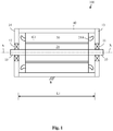
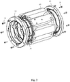
- Fig. 1 shows a side view of an electric machine and figure 2 shows an axonometric view of an electric machine.
- the electric machine 100 may comprise a longitudinal centre axis X-X, a shaft 10, a rotor 20 attached to a centre portion of the shaft 10, a stator 30 surrounding the rotor 20, and a frame 40 surrounding the stator 30.
- the rotor 20 and the stator 30 may be cylindrical.
- Each end of the shaft 10 may be rotatably supported on a bearing 11, 12.
- Each bearing 11, 12 may be supported in a bearing house in a respective end plate 13, 14 of the electric machine 100.
- the end plates 13, 14 may be attached to a respective end of the frame 40.
- the rotor 20 may be provided with a rotor winding (not shown in the figure).
- the stator 30 may comprise a stator core surrounding the rotor 20.
- the stator 30 core may be provided with a stator winding. The figure shows only the winding ends 21A of the stator winding.
- the frame 40 may be supported on a support structure R at the installation site of the electric machine 100.
- the frame 40 may be supported on the support structure R through support feet attached to the outer surface of the frame 40 or through support feet attached to the end plates 13, 14.
- the support feet may be attached e.g. by welding to the frame 40 or to the end plates 13, 14.
- the frame 40 may be attached to the stator 30 with a press-on fit.
- the frame 40 has an axial length L1.
- the frame 40 may be made of a material suitable to be welded. Suitable materials are e.g. steel and aluminium.
- the end plates 13, 14 may be attached with fastening means 15, 16 e.g. screws to the frame 40.
- the screws 15, 16 may extend in the axial X-X direction through the end plates 13, 14 to the end of the frame 40.
- the electric machine 100 can be an electric motor or an electric generator.
- Fig. 3 shows a transverse cross section of a frame of the electric machine.
- the outer broken line A1 in the figure represents the outer circumference of the stator core 30 in the electric machine.
- the inner broken line A2 in the figure represents the inner circumference of the stator core 30 in the electric machine.
- the outer circumference A1 of the stator core 30 corresponds to the inner circumference of the frame 40 of the electric machine.
- the figure shows only one frame module 50 of the frame 40.
- the inner diameter D of the frame 40 is indicated in the figure.
- the frame module 50 comprises an inner surface 51 forming an arc coinciding with the inner circumference A1 of the frame 40, an outer surface 52, and two side edges 53, 54 extending between the ends of the inner surface 51 and the outer surface 52.
- the side edges 53, 54 of the frame module 50 may extend in a radial direction outwards from the circumference A1 of the frame 40.
- the side edges 53, 54 of the frame module 50 may on the other hand extend in an axial direction X-X along the axial length L1 of the frame 40.
- the frame module 50 may further comprise at least one axial cooling duct 55 passing through the frame module 50 in the axial direction.
- the axial cooling duct 55 may be a liquid e.g. water cooling duct.
- the outer surface 52 of the frame module 50 may have any suitable form.
- the outer surface 52 of the frame module 50 may be formed of smooth curves or of angular curves or of a combination of these.
- the inner surface 51 of the frame module 50 may be seated against the outer surface of the stator 30.
- the frame module 50 may be manufactured by extrusion. Extrusion allows for a free adjustment of the axial length of the frame module 50.
- the frame 40 comprises in this embodiment eight identical frame modules 50. Adjacent frame modules 50 may be attached to each other by welding the opposite side edges 53, 54 of the frame modules 50 together along the axial length of the side edges 53, 54 of the frame modules 50. A uniform frame 40 may thus be formed of several frame modules 50.
- An angle ⁇ 1 between a first radius R1 extending from a centre C1 of the inner circumference A1 of the frame 40 to a first side edge 53 of the frame module 50 and a second radius R2 extending from the centre C1 of the inner circumference A1 of the frame 40 to a second side edge 54 of the frame module 50 is thus 45 degrees.
- the centre C1 of the frame 40 coincides with the centre of the electric machine.
- the centre of the frame 40 is situated on the longitudinal centre axis X-X of the electric machine.
- the figure shows also a horizontal centre line X1-X1 of the cross section of the frame 40 and a vertical centre line Y1-Y1 of the cross section of the frame 40.
- the inner diameters of frames 40 for electric machines according to the International Electrotechnical Commission (IEC) frame size standard form nearly an arithmetic series.
- the frame 40 may be manufactured from frame modules 50 so that 8 modules 50 are used for IEC frame 160, 9 modules 50 for IEC frame 180 and 10 modules for IEC 200.
- the arc length of the inner surface 51 of one module 50 in the frame 40 when N modules are used to form the frame 40 is thus ⁇ * 20 [mm].
- the frame modules 50 may be welded together along the axially extending side edges 53, 54 of the frame modules 50.
- the curvature of the inner surface 51 of the arc-shaped frame modules 50 will not initially match the circumference of the stator opening. Machining allowance may therefore be added to the profile of the frame module 50.
- the welded frame 40 may then finally be machined in order to achieve a desired circular inner opening of the frame 40.
- the axial cooling ducts 55 may be connected together at each end of the frame 40. This may be done by machining grooves in a circumferential direction between adjacent cooling ducts 55 at the ends of the frame 40. Another possibility would be to attach an end flange to each end surface of the frame 40.
- the end flange could comprise a circumferential cooling fluid groove machined into the end surface of the end flange that will seat against the end of the frame 40.
- the circumferential centre line of the cooling fluid groove in the end frame may correspond to the circumferential centre line connecting the centres of the axial ducts 55 at the end of the frame 40.
- the fluid inlet passage and the fluid outlet passage could on the other hand be arranged through a frame module 50.
- a radial bore could extend from the outer surface of the frame module 50 to the end of the axial inlet fluid duct.
- a coupling piece could be screwed into the radial bore forming a connection for the inlet for cooling fluid to the machine.
- a radial bore could extend from the outer surface of the frame module 50 to the end of the axial outlet fluid duct.
- a coupling piece could be screwed into the radial bore forming a connection for the outlet for cooling fluid from the machine.
- the frame of the electric machine may be produced by a method comprising producing frame modules 50 having an arc-shaped inner surface 51, the frame modules 50 extending in the axial direction X-X over a length L1 of the frame 40 and in the circumferential direction A over a portion of the circumference of the frame 40, each frame module 50 comprising at least one axial cooling duct 55 passing in the axial direction through the frame module 50, positioning frame modules 50 adjacent to each other so that the arc-shaped inner surface 51 of the frame module 50 seats on an inner circumference A1 of the frame 40, welding adjacent frame modules 50 to each other from the edges 53, 54 of the frame modules 50 in order to form a continuous circular frame 40, machining an inner surface of the frame 40 in order to achieve a circular inner opening of a desired diameter in the frame 40.
- the electric machine may be a liquid cooled electric machine.
- the liquid may be e.g. water or oil.
Landscapes
- Engineering & Computer Science (AREA)
- Power Engineering (AREA)
- Manufacturing & Machinery (AREA)
- Motor Or Generator Frames (AREA)
- Motor Or Generator Cooling System (AREA)
Abstract
Description
- The invention relates to a frame of an electric machine.
- Electric machines i.e. electric motors and electric generators are used in many applications. Electric motors are used to drive different kinds of machines and electric generators are used to produce electric power.
- An electric machine may comprise a rotating shaft, a rotor on the shaft, a stationary stator and a frame. The rotor may be provided with a rotor winding e.g. a squirrel cage or with permanent magnets. The stator may comprise a stator core with a stator winding.
- The shaft may be supported via bearings on end plates, said end plates being attached to the frame.
- The electric machine may be cooled with liquid e.g. water passing in cooling ducts in the frame.
- Water cooled frames have traditionally been manufactured by casting or by using a welded construction. Steel tubes have been embedded in the casting to provide a flow channel for the cooling media. These manufacturing methods might not be the most cost effective especially for smaller electric machines. This is due to the high amount of manual work and/or the high tooling costs. This applies e.g. to electric machines being smaller than IEC 250 i.e. a standard prepared by the International Electrotechnical Commission (IEC) for the frame size of electric machines. The electric machine is in this standard standardized in view of essential parameters of the electric machine.
- The frame could be made e.g. from an extruded tubular profile with integrated water cooling channels, whereby the problem of investing in a new tool for different lengths of the electric machine would be solved. This is due to the fact that the extruded tubular profile may be cut to any desired length. The tooling costs for each separate inner diameter would, however, still remain.
- An object of the present invention is to achieve an improved frame of an electric machine.
- The frame of an electric machine according to the invention is defined in
claim 1. - The frame has an axial direction and a circumferential direction and comprises
frame modules having an arc-shaped inner surface, the frame modules extending in the axial direction over a length of the frame and in the circumferential direction over a portion of the circumference of the frame, adjacent frame modules being attached to each other from the edges of the frame modules in order to form a continuous circular frame having a circular inner opening, each frame module comprising at least one axial cooling duct passing in the axial direction through the frame module. - The use of a modular frame construction according to the invention eliminates the need for a specific tooling for each separate inner diameter.
- The invention makes it possible to use one simple inexpensive extrusion tool in order to manufacture the frame module with the at least one axial cooling duct. The use of the frame module makes it possible to manufacture a frame of a desired length and with a desired diameter. The frame module or the complete frame comprising several frame modules may easily be cut to a desired length. A desired frame in accordance with the corresponding IEC standard may easily be achieved by varying the number of frame modules used in the frame.
- The electric machine may be a liquid cooled electric machine. The liquid may be e.g. water or oil.
- In the following the invention will be described in greater detail by means of preferred embodiments with reference to the attached drawings, in which
-
Figure 1 shows a side view of an electric machine, -
Figure 2 shows an axonometric view of an electric machine, -
Figure 3 shows a transverse cross section of a frame of an electric machine. -
Fig. 1 shows a side view of an electric machine andfigure 2 shows an axonometric view of an electric machine. - The
electric machine 100 may comprise a longitudinal centre axis X-X, ashaft 10, arotor 20 attached to a centre portion of theshaft 10, astator 30 surrounding therotor 20, and aframe 40 surrounding thestator 30. Therotor 20 and thestator 30 may be cylindrical. - Each end of the
shaft 10 may be rotatably supported on abearing respective end plate electric machine 100. Theend plates frame 40. - The
rotor 20 may be provided with a rotor winding (not shown in the figure). - The
stator 30 may comprise a stator core surrounding therotor 20. Thestator 30 core may be provided with a stator winding. The figure shows only thewinding ends 21A of the stator winding. - There is an air gap G1 between the outer surface of the
rotor 20 and the inner surface of thestator 30. - The
frame 40 may be supported on a support structure R at the installation site of theelectric machine 100. Theframe 40 may be supported on the support structure R through support feet attached to the outer surface of theframe 40 or through support feet attached to theend plates frame 40 or to theend plates - The
frame 40 may be attached to thestator 30 with a press-on fit. - The
frame 40 has an axial length L1. - The
frame 40 may be made of a material suitable to be welded. Suitable materials are e.g. steel and aluminium. - The
end plates frame 40. Thescrews end plates frame 40. - The
electric machine 100 can be an electric motor or an electric generator. -
Fig. 3 shows a transverse cross section of a frame of the electric machine. - The outer broken line A1 in the figure represents the outer circumference of the
stator core 30 in the electric machine. The inner broken line A2 in the figure represents the inner circumference of thestator core 30 in the electric machine. The outer circumference A1 of thestator core 30 corresponds to the inner circumference of theframe 40 of the electric machine. The figure shows only oneframe module 50 of theframe 40. The inner diameter D of theframe 40 is indicated in the figure. - The
frame module 50 comprises aninner surface 51 forming an arc coinciding with the inner circumference A1 of theframe 40, anouter surface 52, and twoside edges inner surface 51 and theouter surface 52. Theside edges frame module 50 may extend in a radial direction outwards from the circumference A1 of theframe 40. The side edges 53, 54 of theframe module 50 may on the other hand extend in an axial direction X-X along the axial length L1 of theframe 40. Theframe module 50 may further comprise at least oneaxial cooling duct 55 passing through theframe module 50 in the axial direction. Theaxial cooling duct 55 may be a liquid e.g. water cooling duct. - The
outer surface 52 of theframe module 50 may have any suitable form. Theouter surface 52 of theframe module 50 may be formed of smooth curves or of angular curves or of a combination of these. - The
inner surface 51 of theframe module 50 may be seated against the outer surface of thestator 30. - The
frame module 50 may be manufactured by extrusion. Extrusion allows for a free adjustment of the axial length of theframe module 50. - The
frame 40 comprises in this embodiment eightidentical frame modules 50.Adjacent frame modules 50 may be attached to each other by welding the opposite side edges 53, 54 of theframe modules 50 together along the axial length of the side edges 53, 54 of theframe modules 50. Auniform frame 40 may thus be formed ofseveral frame modules 50. - An angle α1 between a first radius R1 extending from a centre C1 of the inner circumference A1 of the
frame 40 to afirst side edge 53 of theframe module 50 and a second radius R2 extending from the centre C1 of the inner circumference A1 of theframe 40 to asecond side edge 54 of theframe module 50 is thus 45 degrees. The centre C1 of theframe 40 coincides with the centre of the electric machine. The centre of theframe 40 is situated on the longitudinal centre axis X-X of the electric machine. - The figure shows also a horizontal centre line X1-X1 of the cross section of the
frame 40 and a vertical centre line Y1-Y1 of the cross section of theframe 40. - The inner diameters of
frames 40 for electric machines according to the International Electrotechnical Commission (IEC) frame size standard form nearly an arithmetic series. The inner diameters of e.g. IEC frames 160, 180, 200 can be characterized with the following equation D = 20 * N, where N = 8 for IEC 160, N = 9 for IEC 180 and N = 10 for IEC 200. - The
frame 40 may be manufactured fromframe modules 50 so that 8modules 50 are used for IEC frame 160, 9modules 50 forIEC frame 180 and 10 modules for IEC 200. - The length of the inner circumference of the
frame 40 is CF = π * D = π * 20 * N. The arc length of theinner surface 51 of onemodule 50 in theframe 40 when N modules are used to form theframe 40 is thus π * 20 [mm]. - The
frame modules 50 may be welded together along the axially extending side edges 53, 54 of theframe modules 50. The curvature of theinner surface 51 of the arc-shapedframe modules 50 will not initially match the circumference of the stator opening. Machining allowance may therefore be added to the profile of theframe module 50. The weldedframe 40 may then finally be machined in order to achieve a desired circular inner opening of theframe 40. - The
axial cooling ducts 55 may be connected together at each end of theframe 40. This may be done by machining grooves in a circumferential direction betweenadjacent cooling ducts 55 at the ends of theframe 40. Another possibility would be to attach an end flange to each end surface of theframe 40. The end flange could comprise a circumferential cooling fluid groove machined into the end surface of the end flange that will seat against the end of theframe 40. The circumferential centre line of the cooling fluid groove in the end frame may correspond to the circumferential centre line connecting the centres of theaxial ducts 55 at the end of theframe 40. There could further be a radial inlet fluid passage from the radial outer surface of one end flange into the cooling fluid groove in said end flange. There could further be a radial outlet fluid passage from the radial outer surface of the other end plate into the cooling fluid groove in said end flange. Circumferential seals radially at both sides of the cooling fluid groove could be arranged in order to seal the end flange to the end of theframe 40. - The fluid inlet passage and the fluid outlet passage could on the other hand be arranged through a
frame module 50. There could be an axial fluid inlet duct passing from a first end of theframe module 50 only a short distance towards the second end of theframe module 50. A radial bore could extend from the outer surface of theframe module 50 to the end of the axial inlet fluid duct. A coupling piece could be screwed into the radial bore forming a connection for the inlet for cooling fluid to the machine. There could further be an axial fluid outlet duct passing from a second end of theframe module 50 only a short distance towards the first end of theframe module 50. A radial bore could extend from the outer surface of theframe module 50 to the end of the axial outlet fluid duct. A coupling piece could be screwed into the radial bore forming a connection for the outlet for cooling fluid from the machine. - The frame of the electric machine may be produced by a method comprising
producingframe modules 50 having an arc-shapedinner surface 51, theframe modules 50 extending in the axial direction X-X over a length L1 of theframe 40 and in the circumferential direction A over a portion of the circumference of theframe 40, eachframe module 50 comprising at least oneaxial cooling duct 55 passing in the axial direction through theframe module 50,
positioning frame modules 50 adjacent to each other so that the arc-shapedinner surface 51 of theframe module 50 seats on an inner circumference A1 of theframe 40,
weldingadjacent frame modules 50 to each other from theedges frame modules 50 in order to form a continuouscircular frame 40,
machining an inner surface of theframe 40 in order to achieve a circular inner opening of a desired diameter in theframe 40. - The electric machine may be a liquid cooled electric machine. The liquid may be e.g. water or oil.
- It will be obvious to a person skilled in the art that, as the technology advances, the inventive concept can be implemented in various ways. The invention and its embodiments are not limited to the examples described above but may vary within the scope of the claims.
Claims (11)
- A frame of an electric machine, the frame (40) having an axial direction (X-X) and a circumferential direction (A), the frame (40) comprising
frame modules (50) having an arc-shaped inner surface (51), the frame modules (50) extending in the axial direction (X-X) over a length (L1) of the frame (40) and in the circumferential direction (A) over a portion of the circumference of the frame (40), adjacent frame modules (50) being attached to each other from the edges (53, 54) of the frame modules (50) in order to form a continuous circular frame (40) having a circular inner opening, each frame module (50) comprising at least one axial cooling duct (55) passing in the axial direction through the frame module (50). - The frame according to claim 1, wherein an inner diameter of the frame (40) is characterized with the following equation D = 20 * N, where N = 8 for a frame size IEC 160, N = 9 for a frame size IEC 180 and N = 10 for a frame size IEC 200 etc.
- The frame according to claim 1 or 2, wherein an arc-length (A1) of the arc-shaped inner surface (51) of the frame module (50) is π * 20 mm.
- The frame according to any of claims 1 to 3, wherein the axial cooling ducts (55) are connected at each axial (X-X) end of the frame (40) with a circumferential groove at the axial (X-X) end of the frame (40).
- The frame according to any of claims 1 to 4, wherein an inner surface of the frame (40) is finally machined in order to achieve a desired circular inner opening of the frame (40).
- An electric machine comprising a frame (40) according to any of claims 1 to 5.
- The electric machine according to claim 6, wherein the electric machine comprises a rotor (20) and a stator (30) surrounding the rotor (20), the frame surrounding the stator (30).
- The electric machine according to claim 7, wherein the rotor (20) and the stator (30) has a cylindrical shape.
- A method for producing a frame of an electric machine, the method comprising
producing frame modules (50) having an arc-shaped inner surface (51), the frame modules (50) extending in the axial direction (X-X) over a length (L1) of the frame (40) and in the circumferential direction (A) over a portion of the circumference of the frame (40), each frame module (50) comprising at least one axial cooling duct (55) passing in the axial direction through the frame module (50),
positioning frame modules (50) adjacent to each other so that the arc-shaped inner surface (51) of the frame module (50) seats on an inner circumference (A1) of the frame (40),
welding adjacent frame modules (50) to each other from the edges (53, 54) of the frame modules (50) in order to form a continuous circular frame (40),
machining an inner surface of the frame (40) in order to achieve a circular inner opening of a desired diameter in the frame (40). - The method according to claim 9, wherein an inner diameter of the frame (40) is characterized with the following equation D = 20 * N, where N = 8 for a frame size IEC 160, N = 9 for a frame size IEC 180 and N = 10 for a frame size IEC 200 etc.
- The method according to claim 9 or 10, wherein an arc-length (A1) of the arc-shaped inner surface (51) of the frame module (50) is π * 20 mm.
Priority Applications (2)
| Application Number | Priority Date | Filing Date | Title |
|---|---|---|---|
| EP19181405.2A EP3754818B1 (en) | 2019-06-20 | 2019-06-20 | A frame of an electric machine |
| PCT/EP2020/066713 WO2020254374A1 (en) | 2019-06-20 | 2020-06-17 | A frame of an electric machine |
Applications Claiming Priority (1)
| Application Number | Priority Date | Filing Date | Title |
|---|---|---|---|
| EP19181405.2A EP3754818B1 (en) | 2019-06-20 | 2019-06-20 | A frame of an electric machine |
Publications (2)
| Publication Number | Publication Date |
|---|---|
| EP3754818A1 true EP3754818A1 (en) | 2020-12-23 |
| EP3754818B1 EP3754818B1 (en) | 2022-08-24 |
Family
ID=66999685
Family Applications (1)
| Application Number | Title | Priority Date | Filing Date |
|---|---|---|---|
| EP19181405.2A Active EP3754818B1 (en) | 2019-06-20 | 2019-06-20 | A frame of an electric machine |
Country Status (2)
| Country | Link |
|---|---|
| EP (1) | EP3754818B1 (en) |
| WO (1) | WO2020254374A1 (en) |
Citations (1)
| Publication number | Priority date | Publication date | Assignee | Title |
|---|---|---|---|---|
| US20100007227A1 (en) * | 2007-09-20 | 2010-01-14 | Smith Mark C | Cooling jacket for drive motor |
-
2019
- 2019-06-20 EP EP19181405.2A patent/EP3754818B1/en active Active
-
2020
- 2020-06-17 WO PCT/EP2020/066713 patent/WO2020254374A1/en not_active Ceased
Patent Citations (1)
| Publication number | Priority date | Publication date | Assignee | Title |
|---|---|---|---|---|
| US20100007227A1 (en) * | 2007-09-20 | 2010-01-14 | Smith Mark C | Cooling jacket for drive motor |
Also Published As
| Publication number | Publication date |
|---|---|
| WO2020254374A1 (en) | 2020-12-24 |
| EP3754818B1 (en) | 2022-08-24 |
| WO2020254374A8 (en) | 2021-02-25 |
Similar Documents
| Publication | Publication Date | Title |
|---|---|---|
| US8183723B2 (en) | Cooling jacket and stator assembly for rotary electric device | |
| EP1953897A2 (en) | Electric motor cooling jacket | |
| EP0418027A1 (en) | A cooling fan for rotating electrical machinery | |
| US12088149B2 (en) | Cooling system for an electric machine | |
| US12034336B2 (en) | Cooling system for an electric machine having a wound field rotor | |
| EP0623988B1 (en) | Electrical machine | |
| EP3480929B1 (en) | Cooled housing for the stator of a direct drive | |
| EP3217515A1 (en) | Rotor, electric machine and associated method | |
| EP3323192A1 (en) | Adaptor for generator | |
| CN107925313B (en) | compressor | |
| EP3754818B1 (en) | A frame of an electric machine | |
| CN120638807A (en) | A double-stator permanent magnet motor structure | |
| EP3900160A1 (en) | Electric motor having a stator housing part | |
| CN1126901A (en) | Elektrische maschine mit einem axialventilator | |
| EP1484518B1 (en) | Bearing lubricating structure of electric motor | |
| CN119032493A (en) | Axial flux machine for motor vehicles, especially for passenger cars | |
| DE19828406A1 (en) | Electric motor | |
| EP0918936B1 (en) | Drive apparatus, such as a liquid ring machine and a method for driving a drive apparatus, such as transferring fluid | |
| CN114123630A (en) | Electric main shaft core, electric main shaft and motor | |
| US4947539A (en) | Method of manufacturing rotor assembly structure | |
| EP3070816B1 (en) | Method and assembly for cooling an electric machine | |
| EP2920867B1 (en) | Electric motor with a stator | |
| CN215805216U (en) | Submersible tubular pump drainage system with high-thrust water-lubricated bearing structure | |
| JPS61170254A (en) | Liquid cooled motor | |
| CN110732689A (en) | high-precision running electric spindle for machining center |
Legal Events
| Date | Code | Title | Description |
|---|---|---|---|
| PUAI | Public reference made under article 153(3) epc to a published international application that has entered the european phase |
Free format text: ORIGINAL CODE: 0009012 |
|
| STAA | Information on the status of an ep patent application or granted ep patent |
Free format text: STATUS: THE APPLICATION HAS BEEN PUBLISHED |
|
| AK | Designated contracting states |
Kind code of ref document: A1 Designated state(s): AL AT BE BG CH CY CZ DE DK EE ES FI FR GB GR HR HU IE IS IT LI LT LU LV MC MK MT NL NO PL PT RO RS SE SI SK SM TR |
|
| AX | Request for extension of the european patent |
Extension state: BA ME |
|
| STAA | Information on the status of an ep patent application or granted ep patent |
Free format text: STATUS: REQUEST FOR EXAMINATION WAS MADE |
|
| STAA | Information on the status of an ep patent application or granted ep patent |
Free format text: STATUS: EXAMINATION IS IN PROGRESS |
|
| 17P | Request for examination filed |
Effective date: 20210525 |
|
| RBV | Designated contracting states (corrected) |
Designated state(s): AL AT BE BG CH CY CZ DE DK EE ES FI FR GB GR HR HU IE IS IT LI LT LU LV MC MK MT NL NO PL PT RO RS SE SI SK SM TR |
|
| 17Q | First examination report despatched |
Effective date: 20210629 |
|
| RIC1 | Information provided on ipc code assigned before grant |
Ipc: H02K 9/00 20060101ALN20220203BHEP Ipc: H02K 15/14 20060101ALI20220203BHEP Ipc: H02K 5/20 20060101AFI20220203BHEP |
|
| RIC1 | Information provided on ipc code assigned before grant |
Ipc: H02K 9/00 20060101ALN20220217BHEP Ipc: H02K 15/14 20060101ALI20220217BHEP Ipc: H02K 5/20 20060101AFI20220217BHEP |
|
| GRAP | Despatch of communication of intention to grant a patent |
Free format text: ORIGINAL CODE: EPIDOSNIGR1 |
|
| STAA | Information on the status of an ep patent application or granted ep patent |
Free format text: STATUS: GRANT OF PATENT IS INTENDED |
|
| RIC1 | Information provided on ipc code assigned before grant |
Ipc: H02K 9/00 20060101ALN20220221BHEP Ipc: H02K 15/14 20060101ALI20220221BHEP Ipc: H02K 5/20 20060101AFI20220221BHEP |
|
| RIC1 | Information provided on ipc code assigned before grant |
Ipc: H02K 9/00 20060101ALN20220301BHEP Ipc: H02K 15/14 20060101ALI20220301BHEP Ipc: H02K 5/20 20060101AFI20220301BHEP |
|
| INTG | Intention to grant announced |
Effective date: 20220328 |
|
| RAP3 | Party data changed (applicant data changed or rights of an application transferred) |
Owner name: ABB SCHWEIZ AG |
|
| GRAS | Grant fee paid |
Free format text: ORIGINAL CODE: EPIDOSNIGR3 |
|
| GRAA | (expected) grant |
Free format text: ORIGINAL CODE: 0009210 |
|
| STAA | Information on the status of an ep patent application or granted ep patent |
Free format text: STATUS: THE PATENT HAS BEEN GRANTED |
|
| AK | Designated contracting states |
Kind code of ref document: B1 Designated state(s): AL AT BE BG CH CY CZ DE DK EE ES FI FR GB GR HR HU IE IS IT LI LT LU LV MC MK MT NL NO PL PT RO RS SE SI SK SM TR |
|
| REG | Reference to a national code |
Ref country code: CH Ref legal event code: EP |
|
| REG | Reference to a national code |
Ref country code: DE Ref legal event code: R096 Ref document number: 602019018559 Country of ref document: DE |
|
| REG | Reference to a national code |
Ref country code: IE Ref legal event code: FG4D |
|
| REG | Reference to a national code |
Ref country code: AT Ref legal event code: REF Ref document number: 1514351 Country of ref document: AT Kind code of ref document: T Effective date: 20220915 |
|
| REG | Reference to a national code |
Ref country code: LT Ref legal event code: MG9D |
|
| REG | Reference to a national code |
Ref country code: NL Ref legal event code: MP Effective date: 20220824 |
|
| PG25 | Lapsed in a contracting state [announced via postgrant information from national office to epo] |
Ref country code: SE Free format text: LAPSE BECAUSE OF FAILURE TO SUBMIT A TRANSLATION OF THE DESCRIPTION OR TO PAY THE FEE WITHIN THE PRESCRIBED TIME-LIMIT Effective date: 20220824 Ref country code: RS Free format text: LAPSE BECAUSE OF FAILURE TO SUBMIT A TRANSLATION OF THE DESCRIPTION OR TO PAY THE FEE WITHIN THE PRESCRIBED TIME-LIMIT Effective date: 20220824 Ref country code: PT Free format text: LAPSE BECAUSE OF FAILURE TO SUBMIT A TRANSLATION OF THE DESCRIPTION OR TO PAY THE FEE WITHIN THE PRESCRIBED TIME-LIMIT Effective date: 20221226 Ref country code: NO Free format text: LAPSE BECAUSE OF FAILURE TO SUBMIT A TRANSLATION OF THE DESCRIPTION OR TO PAY THE FEE WITHIN THE PRESCRIBED TIME-LIMIT Effective date: 20221124 Ref country code: NL Free format text: LAPSE BECAUSE OF FAILURE TO SUBMIT A TRANSLATION OF THE DESCRIPTION OR TO PAY THE FEE WITHIN THE PRESCRIBED TIME-LIMIT Effective date: 20220824 Ref country code: LV Free format text: LAPSE BECAUSE OF FAILURE TO SUBMIT A TRANSLATION OF THE DESCRIPTION OR TO PAY THE FEE WITHIN THE PRESCRIBED TIME-LIMIT Effective date: 20220824 Ref country code: LT Free format text: LAPSE BECAUSE OF FAILURE TO SUBMIT A TRANSLATION OF THE DESCRIPTION OR TO PAY THE FEE WITHIN THE PRESCRIBED TIME-LIMIT Effective date: 20220824 Ref country code: FI Free format text: LAPSE BECAUSE OF FAILURE TO SUBMIT A TRANSLATION OF THE DESCRIPTION OR TO PAY THE FEE WITHIN THE PRESCRIBED TIME-LIMIT Effective date: 20220824 |
|
| REG | Reference to a national code |
Ref country code: AT Ref legal event code: MK05 Ref document number: 1514351 Country of ref document: AT Kind code of ref document: T Effective date: 20220824 |
|
| PG25 | Lapsed in a contracting state [announced via postgrant information from national office to epo] |
Ref country code: PL Free format text: LAPSE BECAUSE OF FAILURE TO SUBMIT A TRANSLATION OF THE DESCRIPTION OR TO PAY THE FEE WITHIN THE PRESCRIBED TIME-LIMIT Effective date: 20220824 Ref country code: IS Free format text: LAPSE BECAUSE OF FAILURE TO SUBMIT A TRANSLATION OF THE DESCRIPTION OR TO PAY THE FEE WITHIN THE PRESCRIBED TIME-LIMIT Effective date: 20221224 Ref country code: HR Free format text: LAPSE BECAUSE OF FAILURE TO SUBMIT A TRANSLATION OF THE DESCRIPTION OR TO PAY THE FEE WITHIN THE PRESCRIBED TIME-LIMIT Effective date: 20220824 Ref country code: GR Free format text: LAPSE BECAUSE OF FAILURE TO SUBMIT A TRANSLATION OF THE DESCRIPTION OR TO PAY THE FEE WITHIN THE PRESCRIBED TIME-LIMIT Effective date: 20221125 |
|
| PG25 | Lapsed in a contracting state [announced via postgrant information from national office to epo] |
Ref country code: SM Free format text: LAPSE BECAUSE OF FAILURE TO SUBMIT A TRANSLATION OF THE DESCRIPTION OR TO PAY THE FEE WITHIN THE PRESCRIBED TIME-LIMIT Effective date: 20220824 Ref country code: RO Free format text: LAPSE BECAUSE OF FAILURE TO SUBMIT A TRANSLATION OF THE DESCRIPTION OR TO PAY THE FEE WITHIN THE PRESCRIBED TIME-LIMIT Effective date: 20220824 Ref country code: ES Free format text: LAPSE BECAUSE OF FAILURE TO SUBMIT A TRANSLATION OF THE DESCRIPTION OR TO PAY THE FEE WITHIN THE PRESCRIBED TIME-LIMIT Effective date: 20220824 Ref country code: DK Free format text: LAPSE BECAUSE OF FAILURE TO SUBMIT A TRANSLATION OF THE DESCRIPTION OR TO PAY THE FEE WITHIN THE PRESCRIBED TIME-LIMIT Effective date: 20220824 Ref country code: CZ Free format text: LAPSE BECAUSE OF FAILURE TO SUBMIT A TRANSLATION OF THE DESCRIPTION OR TO PAY THE FEE WITHIN THE PRESCRIBED TIME-LIMIT Effective date: 20220824 Ref country code: AT Free format text: LAPSE BECAUSE OF FAILURE TO SUBMIT A TRANSLATION OF THE DESCRIPTION OR TO PAY THE FEE WITHIN THE PRESCRIBED TIME-LIMIT Effective date: 20220824 |
|
| REG | Reference to a national code |
Ref country code: DE Ref legal event code: R097 Ref document number: 602019018559 Country of ref document: DE |
|
| PG25 | Lapsed in a contracting state [announced via postgrant information from national office to epo] |
Ref country code: SK Free format text: LAPSE BECAUSE OF FAILURE TO SUBMIT A TRANSLATION OF THE DESCRIPTION OR TO PAY THE FEE WITHIN THE PRESCRIBED TIME-LIMIT Effective date: 20220824 Ref country code: EE Free format text: LAPSE BECAUSE OF FAILURE TO SUBMIT A TRANSLATION OF THE DESCRIPTION OR TO PAY THE FEE WITHIN THE PRESCRIBED TIME-LIMIT Effective date: 20220824 |
|
| PG25 | Lapsed in a contracting state [announced via postgrant information from national office to epo] |
Ref country code: AL Free format text: LAPSE BECAUSE OF FAILURE TO SUBMIT A TRANSLATION OF THE DESCRIPTION OR TO PAY THE FEE WITHIN THE PRESCRIBED TIME-LIMIT Effective date: 20220824 |
|
| PLBE | No opposition filed within time limit |
Free format text: ORIGINAL CODE: 0009261 |
|
| STAA | Information on the status of an ep patent application or granted ep patent |
Free format text: STATUS: NO OPPOSITION FILED WITHIN TIME LIMIT |
|
| 26N | No opposition filed |
Effective date: 20230525 |
|
| PG25 | Lapsed in a contracting state [announced via postgrant information from national office to epo] |
Ref country code: SI Free format text: LAPSE BECAUSE OF FAILURE TO SUBMIT A TRANSLATION OF THE DESCRIPTION OR TO PAY THE FEE WITHIN THE PRESCRIBED TIME-LIMIT Effective date: 20220824 |
|
| PG25 | Lapsed in a contracting state [announced via postgrant information from national office to epo] |
Ref country code: MC Free format text: LAPSE BECAUSE OF FAILURE TO SUBMIT A TRANSLATION OF THE DESCRIPTION OR TO PAY THE FEE WITHIN THE PRESCRIBED TIME-LIMIT Effective date: 20220824 |
|
| PG25 | Lapsed in a contracting state [announced via postgrant information from national office to epo] |
Ref country code: MC Free format text: LAPSE BECAUSE OF FAILURE TO SUBMIT A TRANSLATION OF THE DESCRIPTION OR TO PAY THE FEE WITHIN THE PRESCRIBED TIME-LIMIT Effective date: 20220824 |
|
| REG | Reference to a national code |
Ref country code: CH Ref legal event code: PL |
|
| REG | Reference to a national code |
Ref country code: BE Ref legal event code: MM Effective date: 20230630 |
|
| PG25 | Lapsed in a contracting state [announced via postgrant information from national office to epo] |
Ref country code: LU Free format text: LAPSE BECAUSE OF NON-PAYMENT OF DUE FEES Effective date: 20230620 |
|
| REG | Reference to a national code |
Ref country code: IE Ref legal event code: MM4A |
|
| PG25 | Lapsed in a contracting state [announced via postgrant information from national office to epo] |
Ref country code: LU Free format text: LAPSE BECAUSE OF NON-PAYMENT OF DUE FEES Effective date: 20230620 |
|
| PG25 | Lapsed in a contracting state [announced via postgrant information from national office to epo] |
Ref country code: IE Free format text: LAPSE BECAUSE OF NON-PAYMENT OF DUE FEES Effective date: 20230620 |
|
| PG25 | Lapsed in a contracting state [announced via postgrant information from national office to epo] |
Ref country code: IE Free format text: LAPSE BECAUSE OF NON-PAYMENT OF DUE FEES Effective date: 20230620 Ref country code: CH Free format text: LAPSE BECAUSE OF NON-PAYMENT OF DUE FEES Effective date: 20230630 |
|
| PG25 | Lapsed in a contracting state [announced via postgrant information from national office to epo] |
Ref country code: IT Free format text: LAPSE BECAUSE OF FAILURE TO SUBMIT A TRANSLATION OF THE DESCRIPTION OR TO PAY THE FEE WITHIN THE PRESCRIBED TIME-LIMIT Effective date: 20220824 Ref country code: BE Free format text: LAPSE BECAUSE OF NON-PAYMENT OF DUE FEES Effective date: 20230630 |
|
| PG25 | Lapsed in a contracting state [announced via postgrant information from national office to epo] |
Ref country code: BG Free format text: LAPSE BECAUSE OF FAILURE TO SUBMIT A TRANSLATION OF THE DESCRIPTION OR TO PAY THE FEE WITHIN THE PRESCRIBED TIME-LIMIT Effective date: 20220824 |
|
| PG25 | Lapsed in a contracting state [announced via postgrant information from national office to epo] |
Ref country code: BG Free format text: LAPSE BECAUSE OF FAILURE TO SUBMIT A TRANSLATION OF THE DESCRIPTION OR TO PAY THE FEE WITHIN THE PRESCRIBED TIME-LIMIT Effective date: 20220824 |
|
| PGFP | Annual fee paid to national office [announced via postgrant information from national office to epo] |
Ref country code: DE Payment date: 20250618 Year of fee payment: 7 |
|
| PGFP | Annual fee paid to national office [announced via postgrant information from national office to epo] |
Ref country code: GB Payment date: 20250618 Year of fee payment: 7 |
|
| PGFP | Annual fee paid to national office [announced via postgrant information from national office to epo] |
Ref country code: FR Payment date: 20250626 Year of fee payment: 7 |
|
| PG25 | Lapsed in a contracting state [announced via postgrant information from national office to epo] |
Ref country code: CY Free format text: LAPSE BECAUSE OF FAILURE TO SUBMIT A TRANSLATION OF THE DESCRIPTION OR TO PAY THE FEE WITHIN THE PRESCRIBED TIME-LIMIT; INVALID AB INITIO Effective date: 20190620 |
|
| PG25 | Lapsed in a contracting state [announced via postgrant information from national office to epo] |
Ref country code: HU Free format text: LAPSE BECAUSE OF FAILURE TO SUBMIT A TRANSLATION OF THE DESCRIPTION OR TO PAY THE FEE WITHIN THE PRESCRIBED TIME-LIMIT; INVALID AB INITIO Effective date: 20190620 |
|
| PG25 | Lapsed in a contracting state [announced via postgrant information from national office to epo] |
Ref country code: TR Free format text: LAPSE BECAUSE OF FAILURE TO SUBMIT A TRANSLATION OF THE DESCRIPTION OR TO PAY THE FEE WITHIN THE PRESCRIBED TIME-LIMIT Effective date: 20220824 |