EP3754802B1 - A retractable cable management device - Google Patents
A retractable cable management device Download PDFInfo
- Publication number
- EP3754802B1 EP3754802B1 EP20180931.6A EP20180931A EP3754802B1 EP 3754802 B1 EP3754802 B1 EP 3754802B1 EP 20180931 A EP20180931 A EP 20180931A EP 3754802 B1 EP3754802 B1 EP 3754802B1
- Authority
- EP
- European Patent Office
- Prior art keywords
- housing
- cable
- opening
- section
- output cable
- Prior art date
- Legal status (The legal status is an assumption and is not a legal conclusion. Google has not performed a legal analysis and makes no representation as to the accuracy of the status listed.)
- Active
Links
Images
Classifications
-
- H—ELECTRICITY
- H02—GENERATION; CONVERSION OR DISTRIBUTION OF ELECTRIC POWER
- H02G—INSTALLATION OF ELECTRIC CABLES OR LINES, OR OF COMBINED OPTICAL AND ELECTRIC CABLES OR LINES
- H02G11/00—Arrangements of electric cables or lines between relatively-movable parts
- H02G11/006—Arrangements of electric cables or lines between relatively-movable parts using extensible carrier for the cable, e.g. self-coiling spring
-
- B—PERFORMING OPERATIONS; TRANSPORTING
- B65—CONVEYING; PACKING; STORING; HANDLING THIN OR FILAMENTARY MATERIAL
- B65H—HANDLING THIN OR FILAMENTARY MATERIAL, e.g. SHEETS, WEBS, CABLES
- B65H75/00—Storing webs, tapes, or filamentary material, e.g. on reels
- B65H75/02—Cores, formers, supports, or holders for coiled, wound, or folded material, e.g. reels, spindles, bobbins, cop tubes, cans, mandrels or chucks
- B65H75/34—Cores, formers, supports, or holders for coiled, wound, or folded material, e.g. reels, spindles, bobbins, cop tubes, cans, mandrels or chucks specially adapted or mounted for storing and repeatedly paying-out and re-storing lengths of material provided for particular purposes, e.g. anchored hoses, power cables
- B65H75/36—Cores, formers, supports, or holders for coiled, wound, or folded material, e.g. reels, spindles, bobbins, cop tubes, cans, mandrels or chucks specially adapted or mounted for storing and repeatedly paying-out and re-storing lengths of material provided for particular purposes, e.g. anchored hoses, power cables without essentially involving the use of a core or former internal to a stored package of material, e.g. with stored material housed within casing or container, or intermittently engaging a plurality of supports as in sinuous or serpentine fashion
- B65H75/362—Cores, formers, supports, or holders for coiled, wound, or folded material, e.g. reels, spindles, bobbins, cop tubes, cans, mandrels or chucks specially adapted or mounted for storing and repeatedly paying-out and re-storing lengths of material provided for particular purposes, e.g. anchored hoses, power cables without essentially involving the use of a core or former internal to a stored package of material, e.g. with stored material housed within casing or container, or intermittently engaging a plurality of supports as in sinuous or serpentine fashion with stored material housed within a casing or container
-
- F—MECHANICAL ENGINEERING; LIGHTING; HEATING; WEAPONS; BLASTING
- F21—LIGHTING
- F21V—FUNCTIONAL FEATURES OR DETAILS OF LIGHTING DEVICES OR SYSTEMS THEREOF; STRUCTURAL COMBINATIONS OF LIGHTING DEVICES WITH OTHER ARTICLES, NOT OTHERWISE PROVIDED FOR
- F21V21/00—Supporting, suspending, or attaching arrangements for lighting devices; Hand grips
- F21V21/34—Supporting elements displaceable along a guiding element
- F21V21/35—Supporting elements displaceable along a guiding element with direct electrical contact between the supporting element and electric conductors running along the guiding element
-
- F—MECHANICAL ENGINEERING; LIGHTING; HEATING; WEAPONS; BLASTING
- F21—LIGHTING
- F21V—FUNCTIONAL FEATURES OR DETAILS OF LIGHTING DEVICES OR SYSTEMS THEREOF; STRUCTURAL COMBINATIONS OF LIGHTING DEVICES WITH OTHER ARTICLES, NOT OTHERWISE PROVIDED FOR
- F21V27/00—Cable-stowing arrangements structurally associated with lighting devices, e.g. reels
-
- F—MECHANICAL ENGINEERING; LIGHTING; HEATING; WEAPONS; BLASTING
- F21—LIGHTING
- F21W—INDEXING SCHEME ASSOCIATED WITH SUBCLASSES F21K, F21L, F21S and F21V, RELATING TO USES OR APPLICATIONS OF LIGHTING DEVICES OR SYSTEMS
- F21W2131/00—Use or application of lighting devices or systems not provided for in codes F21W2102/00-F21W2121/00
- F21W2131/40—Lighting for industrial, commercial, recreational or military use
- F21W2131/405—Lighting for industrial, commercial, recreational or military use for shop-windows or displays
Definitions
- the present invention relates to the field of lighting technology, in particular to a retractable cable management device (wire regulator).
- the power supply cable When installing lamps on the shelves of supermarkets, shopping malls, etc., the power supply cable needs to be led out from the back of the shelf, and then routed along the side bracket under the layer board and then connected to the lamps.
- the power supply cable is mainly fixed on the layer board bracket by a cable buckle with magnet.
- the width of the shelf layer board needs to be adjusted from time to time, which leads to changes in the installation position of the lamp or lighting fixture, and then the length of the cable must also be adjusted to meet the requirements of the installation position of the lamp or lighting fixture, which will increase the workload of the cable management at the same time. Because in the existing design the power supply cable is exposed, a certain length needs to be reserved during installation for subsequent adjustments and installation, which affects the appearance.
- JP 353104262 U discloses a retractable cable management device according to the preamble of claim 1.
- the cable extends from a first port at a first side of a housing to a second port at an opposite second side of the housing, and extends in an S-shaped manner around a pulley that is rotatably mounted at a vertical post that extends through a longitudinal slot 5 provided in an upper surface of the housing.
- the longitudinal position of the vertical post can be varied by sliding in the longitudinal slot. If at all, the longitudinal position of the cable is fixed by a hooking-mechanism.
- JP 2017199889 A discloses another retractable cable management device, comprising a housing that has an input port at a first side and an output port at an opposite second side of the housing.
- the cable is stored inside the housing by loosely winding along the inner peripheral wall of the housing.
- Rollers are supported inside the housing for winding-up the cable inside the housing, and the rollers are rotatably supported in grooves of corresponding shape.
- the housing does not comprise a longitudinal slot.
- JP 410310332 A discloses another retractable cable management device, wherein the cable extends from one of the ports at a first side of the housing to another port at an opposite side of the housing, and is wound in an S-shaped manner around the posts, which extend through longitudinal slots provided in an upper surface of the housing.
- the longitudinal position of the posts can be varied, which will result in a change of the S-shaped course of the cable and in a change of the total external length of the cable outside the housing.
- a partition inside the housing is not disclosed.
- JP 2008270513 A discloses another retractable cable management device.
- the cable is not guided in an S-shape through the housing.
- a tightening mechanism embodied as a fastening knob that can be loosened / tightened by threading is not disclosed.
- a retractable cable management device comprising a strip-shaped housing and a sliding device, wherein the housing is provided with an opening formed (extending) along the length direction of the housing, an input cable is provided at one end of the housing, an output cable is provided at other end of the housing and the two ends of the housing are provided with closed end covers; wherein one end of the sliding device extends into the housing through the opening and is electrically connected to the input cable and the output cable; the sliding device can slide along the length direction of the opening and the extension length of the output cable relative to the housing changes accordingly during sliding.
- the housing is provided with a partition formed along the length direction of the housing, wherein the partition divides the cavity of the housing into an upper cavity and a lower cavity, the opening is provided in the lower cavity portion, the input cable extends from the upper cavity to the other end of the housing and is connected to the output cable as a whole, and the bent portion of the output cable at the other end of the housing connected to the input cable is fixed in the end cover by abutting the corresponding end of the partition, wherein the sliding device is a tightening mechanism with one end inserted into the opening and the other end exposed outside the housing and comprising a limit post that can move along the length direction of the opening and a fastening knob that is threaded to the limit post and has a nut located outside the housing, wherein the moving position of the tightening mechanism relative to the opening can be adjusted by loosening and tightening the fastening know to change the fixed tightness between the tightening mechanism and the housing, and then the length of the output cable extending out of the housing can be
- the input cable is electrically connected to the limit post and one end of the output cable located in the housing is fixed relative to other end of the housing after bypassing the limit post; and wherein, when the fastening knob is loosened, the tightening mechanism can drive the surrounding output cable to move along the length direction of the opening to change the length of the output cable extending out of the housing, and wherein , when the fastening knob is tightened, the tightening mechanism is fixed relative to the opening.
- the limit post comprises a first section located in the housing and a second section located in the opening, wherein the cross-sectional area of the second section is smaller than the cross-sectional area of the first section to form a step, and a side surface of the second section is a plane in contact with the opening.
- the length of the second section is less than the thickness of the housing at the opening, so that when the fastening knob is tightened, the side wall of the opening is clamped between the stepped surface of the step and the nut of the fastening knob.
- the periphery of the first section comprises a sleeve with a concave periphery surface, and the output cable is disposed around the concave surface of the sleeve.
- the sleeve is rotatably connected with the first section.
- a magnetic block is provided on the end cover and the housing is fixed on the to-be-installed surface by means of the magnetic block.
- a cable buckle is sleeved on the output cable.
- the advantage of the present invention is that: the previously exposed power supply cables that need to be reserved for a certain length are replaced by telescopic power supply rails applicable to different shelf widths,
- the extended length of the output cable can be changed relative to the power supply rail, so as to meet the different length requirements of the power supply cable, which avoids the troublesome problem of conventional cable management and makes the operation very convenient.
- Most of the cables are located inside the power supply rail, which makes the whole device neat and beautiful.
- the retractable cable management device comprises a strip-shaped housing 1 and a sliding device.
- the housing 1 is provided with an opening 16 extending along the length direction of the housing 1.
- One end of the housing 1 is provided with an input cable 2 while the other end is provided with an output cable 3.
- One end of the sliding device dips (extends) into the housing 1 through the opening 16 and is electrically connected to the input cable 2 and the output cable 3.
- the sliding device can slide along the length direction of the opening 16. During the sliding process, the extension length of the output cable 3 relative to the housing 1 is changed accordingly. In this way, when installing lamps in shelves with different widths, it is only necessary to adjust the sliding device so that the extension length of the output cable 3 relative to the housing 1 changes correspondingly, which can meet the requirements of lamp installation in the shelves and is very convenient to use.
- the sliding device is a tightening mechanism with one end inserted into the opening 16 and the other end exposed outside the housing 1.
- the tightening mechanism includes a limit post 81 that can move along the length direction of the opening 16, and a fastening knob 82 that is threaded to the limit post 81 and has a nut located outside the housing.
- the input lead 2 is electrically connected to the limit post 81 and the output cable 3 located in one end of the housing 1 is fixed relative to the other end of the housing 1 after bypassing the limit post 81.
- the tightening mechanism can drive the surrounding output cable 3 to move along the length direction of the opening 16 to change the length of the output cable 3 extending out of the housing 1, and when the fastening knob 82 is tightened, the tightening mechanism is fixed relative to the opening 16.
- the limit post 81 includes a first section 811 located in the housing 1 and a second section 812 located in the opening 16.
- the cross-sectional area of the second section 812 is smaller than the cross-sectional area of the first section 811 to form a step.
- the side surface of the second section 812 is a plane in contact with the opening 16 to limit the circumferential rotation of the limit post 81.
- the cross section of the second section 812 is square, and the output cable 3 is arranged in a U-shape around the limit post 81 in the housing 1.
- the sliding device that is, the tightening mechanism
- the sliding device can move along the length direction of the opening 16, because the output cable 3 is disposed around the limit post 81. Therefore, when the limit post 81 moves, the output cable 3 will also move synchronously along the length direction of the opening 16 with the drive of limit post 81.
- the length of the output cable 3 extending out of the housing 1 is adjusted by adjusting the distance between the tightening mechanism and the other end of the housing 1.
- the length of the second section 812 is less than the thickness of the housing 1 at the opening 16, so that when the fastening knob 82 is tightened, the side wall of the opening 16 is clamped between the stepped surface of the step and the nut of the fastening knob 82 to fix the limit post 81 and the fastening knob 82 relative to the length direction of the opening 16.
- the tightening method of the fastening knob 82 can also be designed in other forms.
- the assembly hole disposed on the limit post 81 which is in threaded connection with the screw of the fastening knob 82 is a through hole, the length of the screw is longer than the depth of the through hole.
- the periphery of the first section 811 is also sleeved with a sleeve 83 with a concave periphery surface
- the output cable 3 is disposed around the concave surface of the sleeve 83
- the periphery of the sleeve 83 adopts smooth cambered surface.
- the sleeve 83 is rotatively connected with the first section 811, so as to further reduce the friction between the output cable 3 and the sleeve 83.
- the rotary connection between the sleeve 83 and the first section 811 can be designed in various different forms.
- the sleeve 83 may be directly sleeved outside the first section 811 of the limit post 81, or a bearing may be provided between the sleeve 83 and the first section 811 of the limit post 81, just like a movable pulley.
- it is easy to operate and labor-saving, and is conducive to further reduce the friction of the output cable 3.
- the housing 1 is provided with a partition 17 formed along the length direction of the housing 1.
- the partition 17 divides the cavity of the housing 1 into an upper cavity and a lower cavity, and the opening 16 is provided in the lower cavity.
- the input cable 2 extends from the upper cavity to the other end of the housing 1 and is connected to the output cable 3 as a whole.
- the two ends of the housing 1 are also provided with closed end covers 7, and the bent portion of the output cable 3 at the other end of the housing 1 connected to the input cable 2 is fixed in the end cover 7 by abutting the end of the partition 17. In this way, no other fixing device is needed, which saves material.
- a magnetic block 91 is provided on the end cover 7, and the housing 1 is adsorbed and fixed on the to-be-installed surface of the shelf by means of the magnetic block 91.
- the magnetic block 91 can also be provided on the housing 1. If the power supply rail of the present application is used on non-ferrous shelves, such as wooden shelves, etc., the power supply track can be fixed by bonding, screw connection, or other fixing methods.
- the output cable 3 is provided with a cable buckle 92, which is fixed with the installation surface by means of magnetic attraction, etc.
- a cable buckle 92 can also be provided on the input cable 2.
- the power supply rail of the present application can be applied not only to the installation of shelf lamps, but also to exhibition cabinets, home furnishing and other applications. It is not only applicable to the installation of lamps, but also to the installation and collection of other electrical equipment.
Landscapes
- Engineering & Computer Science (AREA)
- General Engineering & Computer Science (AREA)
- Insertion, Bundling And Securing Of Wires For Electric Apparatuses (AREA)
- Transmission Devices (AREA)
Description
- The present invention relates to the field of lighting technology, in particular to a retractable cable management device (wire regulator).
- When installing lamps on the shelves of supermarkets, shopping malls, etc., the power supply cable needs to be led out from the back of the shelf, and then routed along the side bracket under the layer board and then connected to the lamps. The power supply cable is mainly fixed on the layer board bracket by a cable buckle with magnet.
- In the prior art, the width of the shelf layer board needs to be adjusted from time to time, which leads to changes in the installation position of the lamp or lighting fixture, and then the length of the cable must also be adjusted to meet the requirements of the installation position of the lamp or lighting fixture, which will increase the workload of the cable management at the same time. Because in the existing design the power supply cable is exposed, a certain length needs to be reserved during installation for subsequent adjustments and installation, which affects the appearance.
-
JP 353104262 U claim 1. The cable extends from a first port at a first side of a housing to a second port at an opposite second side of the housing, and extends in an S-shaped manner around a pulley that is rotatably mounted at a vertical post that extends through a longitudinal slot 5 provided in an upper surface of the housing. For varying the extending length of the cable outside the housing, the longitudinal position of the vertical post can be varied by sliding in the longitudinal slot. If at all, the longitudinal position of the cable is fixed by a hooking-mechanism. -
JP 2017199889 A -
JP 410310332 A -
JP 2008270513 A - In view of the above problems, it is an object of the present invention to provide a retractable cable management device (wire regulator) that can be adjusted in length according to changes in the width of the shelf and the position of the lamp or lighting fixture, and is convenient to operate and has a beautiful appearance.
- This problem is solved by a retractable cable management device as claimed by
claim 1. Further advantageous embodiments are the subject-matter of the dependent claims. - According to the present invention there is provided a retractable cable management device (wire regulator), comprising a strip-shaped housing and a sliding device, wherein the housing is provided with an opening formed (extending) along the length direction of the housing, an input cable is provided at one end of the housing, an output cable is provided at other end of the housing and the two ends of the housing are provided with closed end covers; wherein one end of the sliding device extends into the housing through the opening and is electrically connected to the input cable and the output cable; the sliding device can slide along the length direction of the opening and the extension length of the output cable relative to the housing changes accordingly during sliding.
- According to the present invention the housing is provided with a partition formed along the length direction of the housing, wherein the partition divides the cavity of the housing into an upper cavity and a lower cavity, the opening is provided in the lower cavity portion, the input cable extends from the upper cavity to the other end of the housing and is connected to the output cable as a whole, and the bent portion of the output cable at the other end of the housing connected to the input cable is fixed in the end cover by abutting the corresponding end of the partition, wherein the sliding device is a tightening mechanism with one end inserted into the opening and the other end exposed outside the housing and comprising a limit post that can move along the length direction of the opening and a fastening knob that is threaded to the limit post and has a nut located outside the housing, wherein the moving position of the tightening mechanism relative to the opening can be adjusted by loosening and tightening the fastening know to change the fixed tightness between the tightening mechanism and the housing, and then the length of the output cable extending out of the housing can be changed.
- Advantageously, the input cable is electrically connected to the limit post and one end of the output cable located in the housing is fixed relative to other end of the housing after bypassing the limit post; and wherein, when the fastening knob is loosened, the tightening mechanism can drive the surrounding output cable to move along the length direction of the opening to change the length of the output cable extending out of the housing, and wherein , when the fastening knob is tightened, the tightening mechanism is fixed relative to the opening.
- Advantageously, the limit post comprises a first section located in the housing and a second section located in the opening, wherein the cross-sectional area of the second section is smaller than the cross-sectional area of the first section to form a step, and a side surface of the second section is a plane in contact with the opening.
- Advantageously, the length of the second section is less than the thickness of the housing at the opening, so that when the fastening knob is tightened, the side wall of the opening is clamped between the stepped surface of the step and the nut of the fastening knob.
- Advantageously, the periphery of the first section comprises a sleeve with a concave periphery surface, and the output cable is disposed around the concave surface of the sleeve.
- Advantageously, the sleeve is rotatably connected with the first section.
- Advantageously, a magnetic block is provided on the end cover and the housing is fixed on the to-be-installed surface by means of the magnetic block.
- Advantageously, a cable buckle is sleeved on the output cable.
- Compared with the prior art, the advantage of the present invention is that: the previously exposed power supply cables that need to be reserved for a certain length are replaced by telescopic power supply rails applicable to different shelf widths, When installing the lamp, by adjusting the sliding device of the power supply rail, the extended length of the output cable can be changed relative to the power supply rail, so as to meet the different length requirements of the power supply cable, which avoids the troublesome problem of conventional cable management and makes the operation very convenient. Most of the cables are located inside the power supply rail, which makes the whole device neat and beautiful.
-
-
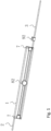
FIG. 1 is a schematic structural diagram of an embodiment of an retractable cable management device of the present invention. -
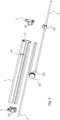
FIG. 2 is a schematic diagram of the explosion structure ofFIG. 1 . -
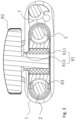
FIG. 3 is a schematic cross-sectional structure diagram ofFIG. 1 . - Hereinafter, specific embodiments of the present invention will be described in further detail based on the drawings. It should be understood that the description of the embodiments of the present invention is not intended to limit the protection scope of the present invention.
- As shown in
FIG 1 to 3 , the retractable cable management device comprises a strip-shaped housing 1 and a sliding device. Thehousing 1 is provided with an opening 16 extending along the length direction of thehousing 1. One end of thehousing 1 is provided with aninput cable 2 while the other end is provided with anoutput cable 3. One end of the sliding device dips (extends) into thehousing 1 through theopening 16 and is electrically connected to theinput cable 2 and theoutput cable 3. The sliding device can slide along the length direction of theopening 16. During the sliding process, the extension length of theoutput cable 3 relative to thehousing 1 is changed accordingly. In this way, when installing lamps in shelves with different widths, it is only necessary to adjust the sliding device so that the extension length of theoutput cable 3 relative to thehousing 1 changes correspondingly, which can meet the requirements of lamp installation in the shelves and is very convenient to use. - More specifically, the sliding device is a tightening mechanism with one end inserted into the
opening 16 and the other end exposed outside thehousing 1. By changing the fixed tightness between the tightening mechanism and thehousing 1, the moving position of the tightening mechanism relative to theopening 16 can be adjusted, so that the length of theoutput cable 3 extending out of thehousing 1 can be changed. - As shown in
Figs. 1 to 3 , the tightening mechanism includes alimit post 81 that can move along the length direction of theopening 16, and afastening knob 82 that is threaded to thelimit post 81 and has a nut located outside the housing. Theinput lead 2 is electrically connected to thelimit post 81 and theoutput cable 3 located in one end of thehousing 1 is fixed relative to the other end of thehousing 1 after bypassing thelimit post 81. When thefastening knob 82 is loosened, the tightening mechanism can drive the surroundingoutput cable 3 to move along the length direction of theopening 16 to change the length of theoutput cable 3 extending out of thehousing 1, and when thefastening knob 82 is tightened, the tightening mechanism is fixed relative to theopening 16. - Please refer to
FIG. 3 together. Thelimit post 81 includes afirst section 811 located in thehousing 1 and asecond section 812 located in the opening 16. The cross-sectional area of thesecond section 812 is smaller than the cross-sectional area of thefirst section 811 to form a step. The side surface of thesecond section 812 is a plane in contact with theopening 16 to limit the circumferential rotation of thelimit post 81. The cross section of thesecond section 812 is square, and theoutput cable 3 is arranged in a U-shape around thelimit post 81 in thehousing 1. - When the
fastening knob 82 is loosened, the sliding device, that is, the tightening mechanism, can move along the length direction of theopening 16, because theoutput cable 3 is disposed around thelimit post 81. Therefore, when thelimit post 81 moves, theoutput cable 3 will also move synchronously along the length direction of theopening 16 with the drive oflimit post 81. Thus, the length of theoutput cable 3 extending out of thehousing 1 is adjusted by adjusting the distance between the tightening mechanism and the other end of thehousing 1. When thefastening knob 82 is fixed, the sliding device, that is, the tightening mechanism, is fixed relative to theopening 16, thereby fixing the extension length of theoutput cable 3. - In this embodiment, the length of the
second section 812 is less than the thickness of thehousing 1 at theopening 16, so that when thefastening knob 82 is tightened, the side wall of theopening 16 is clamped between the stepped surface of the step and the nut of thefastening knob 82 to fix thelimit post 81 and thefastening knob 82 relative to the length direction of theopening 16. Of course, the tightening method of thefastening knob 82 can also be designed in other forms. For example, the assembly hole disposed on thelimit post 81 which is in threaded connection with the screw of thefastening knob 82 is a through hole, the length of the screw is longer than the depth of the through hole. When thefastening knob 82 is tightened, the free end of the screw of thefastening knob 82 abuts against the wall of thehousing 1, and the stepped surface of thelimit post 81 abuts against the inner wall of thehousing 1 at theopening 16, so that thelimit post 81 and the fastening knob is fixed relative to the length direction ofopening 16. - In this embodiment, the periphery of the
first section 811 is also sleeved with asleeve 83 with a concave periphery surface, theoutput cable 3 is disposed around the concave surface of thesleeve 83, and the periphery of thesleeve 83 adopts smooth cambered surface. In this way, when adjusting the extension length of theoutput cable 3, on the one hand, it can avoid theoutput cable 3 slipping to both ends of thefirst section 811 and getting stuck; on the other hand, it can reduce the friction betweenoutput cable 3 andsleeve 83, reduce the wear of the outer insulation layer ofoutput cable 3, and increase the service life ofoutput cable 3. As a preferred method, thesleeve 83 is rotatively connected with thefirst section 811, so as to further reduce the friction between theoutput cable 3 and thesleeve 83. Of course, the rotary connection between thesleeve 83 and thefirst section 811 can be designed in various different forms. For example, thesleeve 83 may be directly sleeved outside thefirst section 811 of thelimit post 81, or a bearing may be provided between thesleeve 83 and thefirst section 811 of thelimit post 81, just like a movable pulley. Thus, it is easy to operate and labor-saving, and is conducive to further reduce the friction of theoutput cable 3. - In this embodiment, the
housing 1 is provided with apartition 17 formed along the length direction of thehousing 1. Thepartition 17 divides the cavity of thehousing 1 into an upper cavity and a lower cavity, and theopening 16 is provided in the lower cavity. Theinput cable 2 extends from the upper cavity to the other end of thehousing 1 and is connected to theoutput cable 3 as a whole. The two ends of thehousing 1 are also provided with closed end covers 7, and the bent portion of theoutput cable 3 at the other end of thehousing 1 connected to theinput cable 2 is fixed in theend cover 7 by abutting the end of thepartition 17. In this way, no other fixing device is needed, which saves material. - Since most of the existing shelves use iron shelves, in order to facilitate the fixing of the power supply rail, a
magnetic block 91 is provided on theend cover 7, and thehousing 1 is adsorbed and fixed on the to-be-installed surface of the shelf by means of themagnetic block 91. Of course, it is conceivable that themagnetic block 91 can also be provided on thehousing 1. If the power supply rail of the present application is used on non-ferrous shelves, such as wooden shelves, etc., the power supply track can be fixed by bonding, screw connection, or other fixing methods. - In this application, in order to avoid the
output cable 3 protruding too long relative to thehousing 1 and sagging, theoutput cable 3 is provided with acable buckle 92, which is fixed with the installation surface by means of magnetic attraction, etc. Of course, acable buckle 92 can also be provided on theinput cable 2. - It should be noted that the power supply rail of the present application can be applied not only to the installation of shelf lamps, but also to exhibition cabinets, home furnishing and other applications. It is not only applicable to the installation of lamps, but also to the installation and collection of other electrical equipment.
- The above disclosure has been described by way of example and in terms of exemplary embodiment, and it is to be understood that the disclosure is not limited thereto. The scope of the invention as set forth in the appended claims.
Claims (8)
- A retractable cable management device, comprising a strip-shaped housing (1) and a sliding device; whereinthe housing (1) is provided with an opening (16) formed along the length direction of the housing (1), an input cable (2) is provided at one end of the housing (1), an output cable (3) is provided at the other end of the housing (1), and the two ends of the housing (1) are provided with closed end covers (7); andone end of the sliding device extends into the housing (1) through the opening (16) and is electrically connected to the input cable (2) and the output cable (3); whereinthe sliding device can slide along the length direction of the opening (16) and the extension length of the output cable (3) relative to the housing (1) changes accordingly during sliding;wherein the sliding device is a tightening mechanism with one end inserted into the opening (16), the other end exposed outside the housing (1) and comprising a limit post (81) that can move along the length direction of the opening (16), characterized by a fastening knob (82) that is threaded to the limit post (81) and has a nut located outside the housing (1), whereinthe moving position of the tightening mechanism relative to the opening (16) can be adjusted by loosening and tightening the fastening knob (82) to change the fixed tightness between the tightening mechanism and the housing (1) so that the length of the output cable (3) extending out of the housing (1) can be changed, andthe housing (1) is provided with a partition (17) formed along the length direction of the housing (1),the partition (17) divides the cavity of the housing (1) into an upper cavity and a lower cavity,the opening (16) is provided in the lower cavity portion,the input cable (2) extends from the upper cavity to the other end of the housing (1) and is connected to the output cable (3) as a whole, anda bent portion of the output cable (3) at the other end of the housing (1) connected to the input cable (2) is fixed in the end cover (7) by abutting the corresponding end of the partition (17).
- The retractable cable management device as claimed in claim 1, whereinthe input cable (2) is electrically connected to the limit post (81) and the one end of the output cable (3) located in the housing (1) is fixed relative to the other end of the housing (1) after bypassing the limit post (81); whereinwhen the fastening knob (82) is loosened, the tightening mechanism can drive the surrounding output cable (3) to move along the length direction of the opening (16) to change the length of the output cable (3) extending out of the housing (1), andwhen the fastening knob (82) is tightened, the tightening mechanism is fixed relative to the opening (16).
- The retractable cable management device as claimed in claim 2, whereinthe limit post (81) comprises a first section (811) located in the housing (1) and a second section (812) located in the opening (16),the cross-sectional area of the second section (812) is smaller than the cross-sectional area of the first section (811) to form a step, anda side surface of the second section (812) is a plane in contact with the opening (16).
- The retractable cable management device as claimed in claim 3, wherein the length of the second section (812) is less than the thickness of the housing (1) at the opening (16), so that when the fastening knob (82) is tightened, the side wall of the opening (16) is clamped between the stepped surface of the step and the nut of the fastening knob (82).
- The retractable cable management device as claimed in claim 3, wherein the periphery of the first section (811) further comprises a sleeve (83) with a concave periphery surface, and the output cable (3) is disposed around the concave surface of the sleeve (83).
- The retractable cable management device as claimed in claim 5, wherein the sleeve (83) is rotatably connected with the first section (811).
- The retractable cable management device as claimed in any of the preceding claims, wherein a magnetic block (91) is provided on the end cover (7), and the housing (1) is fixable on the to-be-installed surface through the magnetic block (91).
- The retractable cable management device as claimed in any of the preceding claims, wherein a cable buckle (92) is sleeved on the output cable (3).
Applications Claiming Priority (1)
| Application Number | Priority Date | Filing Date | Title |
|---|---|---|---|
| CN201910546480.4A CN110307531A (en) | 2019-06-21 | 2019-06-21 | A retractable cable manager |
Publications (2)
| Publication Number | Publication Date |
|---|---|
| EP3754802A1 EP3754802A1 (en) | 2020-12-23 |
| EP3754802B1 true EP3754802B1 (en) | 2023-06-14 |
Family
ID=68076259
Family Applications (1)
| Application Number | Title | Priority Date | Filing Date |
|---|---|---|---|
| EP20180931.6A Active EP3754802B1 (en) | 2019-06-21 | 2020-06-18 | A retractable cable management device |
Country Status (2)
| Country | Link |
|---|---|
| EP (1) | EP3754802B1 (en) |
| CN (1) | CN110307531A (en) |
Families Citing this family (4)
| Publication number | Priority date | Publication date | Assignee | Title |
|---|---|---|---|---|
| CN111162498B (en) * | 2019-12-02 | 2025-02-11 | 赛尔富电子有限公司 | A waterproof power rail with retractable conductors |
| CN111082270B (en) * | 2020-01-03 | 2025-02-18 | 赛尔富电子有限公司 | A shelf power supply device |
| CN112325083B (en) * | 2020-11-19 | 2025-04-01 | 东莞市宏联电子有限公司 | Display stand capable of storing connecting wires |
| CN120402865B (en) * | 2025-07-02 | 2025-10-17 | 高邮市鼎天高分子材料有限公司 | Telescopic power line for energy-saving LED lamp and energy-saving LED lamp |
Family Cites Families (12)
| Publication number | Priority date | Publication date | Assignee | Title |
|---|---|---|---|---|
| JPS5940471Y2 (en) * | 1977-01-24 | 1984-11-16 | アイシン精機株式会社 | Power cord storage device for hand knitting machines |
| US5041002A (en) * | 1990-04-17 | 1991-08-20 | Byrne Norman R | Extendable electrical junction assembly |
| JPH10310332A (en) * | 1997-05-14 | 1998-11-24 | Sony Corp | Cable storage |
| JP4979446B2 (en) * | 2007-04-20 | 2012-07-18 | 三和電気工業株式会社 | Extra length storage box |
| EP2813455A1 (en) * | 2013-06-11 | 2014-12-17 | Lista Office AG | Cable holder and cable assembly |
| JP2017199889A (en) * | 2016-05-01 | 2017-11-02 | 竜三 塚本 | Code case |
| CN107565245A (en) * | 2017-03-27 | 2018-01-09 | 深圳市海盾五金工具有限公司 | A kind of length-adjustable new-energy automobile charging wire |
| CN206806676U (en) * | 2017-04-10 | 2017-12-26 | 东莞市川拓电子有限公司 | A retractable data cable |
| CN208883227U (en) * | 2018-09-10 | 2019-05-21 | 太若科技(北京)有限公司 | Flexible cable container structure and data line accommodating component |
| CN208970889U (en) * | 2018-12-04 | 2019-06-11 | 深圳市跃登电业有限公司 | A multifunctional lightweight data cable |
| CN208951839U (en) * | 2018-12-05 | 2019-06-07 | 中山悦美光电有限公司 | A kind of novel light projector |
| CN210267155U (en) * | 2019-06-21 | 2020-04-07 | 赛尔富电子有限公司 | Telescopic wire arranging device |
-
2019
- 2019-06-21 CN CN201910546480.4A patent/CN110307531A/en active Pending
-
2020
- 2020-06-18 EP EP20180931.6A patent/EP3754802B1/en active Active
Also Published As
| Publication number | Publication date |
|---|---|
| CN110307531A (en) | 2019-10-08 |
| EP3754802A1 (en) | 2020-12-23 |
Similar Documents
| Publication | Publication Date | Title |
|---|---|---|
| EP3754802A1 (en) | A retractable cable management device | |
| US11528991B2 (en) | Shelf power supply system | |
| US11456587B2 (en) | Telescopic power supply track | |
| US10323822B2 (en) | Lighting arrangement, construction kit for a lighting arrangement, and method for constructing a lighting arrangement | |
| US11079081B2 (en) | Panel light mounting structure, a panel light and mounting method thereof | |
| EP3754794B1 (en) | Telescopic power supply track | |
| KR20080112556A (en) | Lamp lifter | |
| CN210624104U (en) | Support fixing device of building electrical equipment machine box | |
| CN210267155U (en) | Telescopic wire arranging device | |
| US20210332960A1 (en) | Structure for mounting a wall lamp | |
| JP7697128B2 (en) | Direct Drive Motors and Smart Devices | |
| CN211573092U (en) | Linear motor structure for sliding door | |
| CN209266799U (en) | Brush assembly of electric, sliding door external power set and sliding door power supply system | |
| KR20020075192A (en) | Cable fixing device | |
| ATE160470T1 (en) | WALL INSTALLATION CHANNEL FOR ELECTRICAL INSTALLATION DEVICES | |
| CN109707215B (en) | Door lock support structure | |
| CN211502714U (en) | Telescopic electricity getting track | |
| CN104007298B (en) | The hiding slideway that a kind of ammeter is drawn | |
| US20060274537A1 (en) | Lamp assembly with a rotatably adjustable photocell adapter | |
| CN214850182U (en) | Novel hedgehog hydnum fastener | |
| KR200397073Y1 (en) | double wind type the national flag-hoisting devise | |
| CN214506470U (en) | Novel wiring structure for building | |
| CN223462556U (en) | Power supply structure of sliding door and shower room | |
| CN223135953U (en) | Automatic door system and fume hood | |
| CN113582063A (en) | Driving mechanism of electric clothes hanger |
Legal Events
| Date | Code | Title | Description |
|---|---|---|---|
| PUAI | Public reference made under article 153(3) epc to a published international application that has entered the european phase |
Free format text: ORIGINAL CODE: 0009012 |
|
| STAA | Information on the status of an ep patent application or granted ep patent |
Free format text: STATUS: THE APPLICATION HAS BEEN PUBLISHED |
|
| AK | Designated contracting states |
Kind code of ref document: A1 Designated state(s): AL AT BE BG CH CY CZ DE DK EE ES FI FR GB GR HR HU IE IS IT LI LT LU LV MC MK MT NL NO PL PT RO RS SE SI SK SM TR |
|
| AX | Request for extension of the european patent |
Extension state: BA ME |
|
| STAA | Information on the status of an ep patent application or granted ep patent |
Free format text: STATUS: REQUEST FOR EXAMINATION WAS MADE |
|
| 17P | Request for examination filed |
Effective date: 20210529 |
|
| RBV | Designated contracting states (corrected) |
Designated state(s): AL AT BE BG CH CY CZ DE DK EE ES FI FR GB GR HR HU IE IS IT LI LT LU LV MC MK MT NL NO PL PT RO RS SE SI SK SM TR |
|
| GRAP | Despatch of communication of intention to grant a patent |
Free format text: ORIGINAL CODE: EPIDOSNIGR1 |
|
| STAA | Information on the status of an ep patent application or granted ep patent |
Free format text: STATUS: GRANT OF PATENT IS INTENDED |
|
| INTG | Intention to grant announced |
Effective date: 20220930 |
|
| RIC1 | Information provided on ipc code assigned before grant |
Ipc: F21V 27/00 20060101ALN20220920BHEP Ipc: F21V 21/35 20060101ALN20220920BHEP Ipc: B65H 75/36 20060101ALI20220920BHEP Ipc: H02G 11/00 20060101AFI20220920BHEP |
|
| GRAJ | Information related to disapproval of communication of intention to grant by the applicant or resumption of examination proceedings by the epo deleted |
Free format text: ORIGINAL CODE: EPIDOSDIGR1 |
|
| STAA | Information on the status of an ep patent application or granted ep patent |
Free format text: STATUS: REQUEST FOR EXAMINATION WAS MADE |
|
| GRAP | Despatch of communication of intention to grant a patent |
Free format text: ORIGINAL CODE: EPIDOSNIGR1 |
|
| STAA | Information on the status of an ep patent application or granted ep patent |
Free format text: STATUS: GRANT OF PATENT IS INTENDED |
|
| INTC | Intention to grant announced (deleted) | ||
| RIC1 | Information provided on ipc code assigned before grant |
Ipc: F21V 27/00 20060101ALN20221214BHEP Ipc: F21V 21/35 20060101ALN20221214BHEP Ipc: B65H 75/36 20060101ALI20221214BHEP Ipc: H02G 11/00 20060101AFI20221214BHEP |
|
| INTG | Intention to grant announced |
Effective date: 20230109 |
|
| RIC1 | Information provided on ipc code assigned before grant |
Ipc: F21V 27/00 20060101ALN20221216BHEP Ipc: F21V 21/35 20060101ALN20221216BHEP Ipc: B65H 75/36 20060101ALI20221216BHEP Ipc: H02G 11/00 20060101AFI20221216BHEP |
|
| GRAS | Grant fee paid |
Free format text: ORIGINAL CODE: EPIDOSNIGR3 |
|
| GRAA | (expected) grant |
Free format text: ORIGINAL CODE: 0009210 |
|
| STAA | Information on the status of an ep patent application or granted ep patent |
Free format text: STATUS: THE PATENT HAS BEEN GRANTED |
|
| AK | Designated contracting states |
Kind code of ref document: B1 Designated state(s): AL AT BE BG CH CY CZ DE DK EE ES FI FR GB GR HR HU IE IS IT LI LT LU LV MC MK MT NL NO PL PT RO RS SE SI SK SM TR |
|
| REG | Reference to a national code |
Ref country code: CH Ref legal event code: EP |
|
| REG | Reference to a national code |
Ref country code: DE Ref legal event code: R096 Ref document number: 602020012432 Country of ref document: DE |
|
| REG | Reference to a national code |
Ref country code: AT Ref legal event code: REF Ref document number: 1579942 Country of ref document: AT Kind code of ref document: T Effective date: 20230715 |
|
| REG | Reference to a national code |
Ref country code: LT Ref legal event code: MG9D |
|
| REG | Reference to a national code |
Ref country code: NL Ref legal event code: MP Effective date: 20230614 |
|
| PG25 | Lapsed in a contracting state [announced via postgrant information from national office to epo] |
Ref country code: SE Free format text: LAPSE BECAUSE OF FAILURE TO SUBMIT A TRANSLATION OF THE DESCRIPTION OR TO PAY THE FEE WITHIN THE PRESCRIBED TIME-LIMIT Effective date: 20230614 Ref country code: NO Free format text: LAPSE BECAUSE OF FAILURE TO SUBMIT A TRANSLATION OF THE DESCRIPTION OR TO PAY THE FEE WITHIN THE PRESCRIBED TIME-LIMIT Effective date: 20230914 Ref country code: ES Free format text: LAPSE BECAUSE OF FAILURE TO SUBMIT A TRANSLATION OF THE DESCRIPTION OR TO PAY THE FEE WITHIN THE PRESCRIBED TIME-LIMIT Effective date: 20230614 |
|
| REG | Reference to a national code |
Ref country code: AT Ref legal event code: MK05 Ref document number: 1579942 Country of ref document: AT Kind code of ref document: T Effective date: 20230614 |
|
| PG25 | Lapsed in a contracting state [announced via postgrant information from national office to epo] |
Ref country code: RS Free format text: LAPSE BECAUSE OF FAILURE TO SUBMIT A TRANSLATION OF THE DESCRIPTION OR TO PAY THE FEE WITHIN THE PRESCRIBED TIME-LIMIT Effective date: 20230614 Ref country code: NL Free format text: LAPSE BECAUSE OF FAILURE TO SUBMIT A TRANSLATION OF THE DESCRIPTION OR TO PAY THE FEE WITHIN THE PRESCRIBED TIME-LIMIT Effective date: 20230614 Ref country code: LV Free format text: LAPSE BECAUSE OF FAILURE TO SUBMIT A TRANSLATION OF THE DESCRIPTION OR TO PAY THE FEE WITHIN THE PRESCRIBED TIME-LIMIT Effective date: 20230614 Ref country code: LT Free format text: LAPSE BECAUSE OF FAILURE TO SUBMIT A TRANSLATION OF THE DESCRIPTION OR TO PAY THE FEE WITHIN THE PRESCRIBED TIME-LIMIT Effective date: 20230614 Ref country code: HR Free format text: LAPSE BECAUSE OF FAILURE TO SUBMIT A TRANSLATION OF THE DESCRIPTION OR TO PAY THE FEE WITHIN THE PRESCRIBED TIME-LIMIT Effective date: 20230614 Ref country code: GR Free format text: LAPSE BECAUSE OF FAILURE TO SUBMIT A TRANSLATION OF THE DESCRIPTION OR TO PAY THE FEE WITHIN THE PRESCRIBED TIME-LIMIT Effective date: 20230915 |
|
| PG25 | Lapsed in a contracting state [announced via postgrant information from national office to epo] |
Ref country code: FI Free format text: LAPSE BECAUSE OF FAILURE TO SUBMIT A TRANSLATION OF THE DESCRIPTION OR TO PAY THE FEE WITHIN THE PRESCRIBED TIME-LIMIT Effective date: 20230614 |
|
| PG25 | Lapsed in a contracting state [announced via postgrant information from national office to epo] |
Ref country code: SK Free format text: LAPSE BECAUSE OF FAILURE TO SUBMIT A TRANSLATION OF THE DESCRIPTION OR TO PAY THE FEE WITHIN THE PRESCRIBED TIME-LIMIT Effective date: 20230614 |
|
| PG25 | Lapsed in a contracting state [announced via postgrant information from national office to epo] |
Ref country code: IS Free format text: LAPSE BECAUSE OF FAILURE TO SUBMIT A TRANSLATION OF THE DESCRIPTION OR TO PAY THE FEE WITHIN THE PRESCRIBED TIME-LIMIT Effective date: 20231014 |
|
| PG25 | Lapsed in a contracting state [announced via postgrant information from national office to epo] |
Ref country code: SM Free format text: LAPSE BECAUSE OF FAILURE TO SUBMIT A TRANSLATION OF THE DESCRIPTION OR TO PAY THE FEE WITHIN THE PRESCRIBED TIME-LIMIT Effective date: 20230614 Ref country code: SK Free format text: LAPSE BECAUSE OF FAILURE TO SUBMIT A TRANSLATION OF THE DESCRIPTION OR TO PAY THE FEE WITHIN THE PRESCRIBED TIME-LIMIT Effective date: 20230614 Ref country code: RO Free format text: LAPSE BECAUSE OF FAILURE TO SUBMIT A TRANSLATION OF THE DESCRIPTION OR TO PAY THE FEE WITHIN THE PRESCRIBED TIME-LIMIT Effective date: 20230614 Ref country code: PT Free format text: LAPSE BECAUSE OF FAILURE TO SUBMIT A TRANSLATION OF THE DESCRIPTION OR TO PAY THE FEE WITHIN THE PRESCRIBED TIME-LIMIT Effective date: 20231016 Ref country code: IS Free format text: LAPSE BECAUSE OF FAILURE TO SUBMIT A TRANSLATION OF THE DESCRIPTION OR TO PAY THE FEE WITHIN THE PRESCRIBED TIME-LIMIT Effective date: 20231014 Ref country code: EE Free format text: LAPSE BECAUSE OF FAILURE TO SUBMIT A TRANSLATION OF THE DESCRIPTION OR TO PAY THE FEE WITHIN THE PRESCRIBED TIME-LIMIT Effective date: 20230614 Ref country code: CZ Free format text: LAPSE BECAUSE OF FAILURE TO SUBMIT A TRANSLATION OF THE DESCRIPTION OR TO PAY THE FEE WITHIN THE PRESCRIBED TIME-LIMIT Effective date: 20230614 Ref country code: AT Free format text: LAPSE BECAUSE OF FAILURE TO SUBMIT A TRANSLATION OF THE DESCRIPTION OR TO PAY THE FEE WITHIN THE PRESCRIBED TIME-LIMIT Effective date: 20230614 |
|
| REG | Reference to a national code |
Ref country code: CH Ref legal event code: PL |
|
| REG | Reference to a national code |
Ref country code: BE Ref legal event code: MM Effective date: 20230630 |
|
| PG25 | Lapsed in a contracting state [announced via postgrant information from national office to epo] |
Ref country code: PL Free format text: LAPSE BECAUSE OF FAILURE TO SUBMIT A TRANSLATION OF THE DESCRIPTION OR TO PAY THE FEE WITHIN THE PRESCRIBED TIME-LIMIT Effective date: 20230614 |
|
| PG25 | Lapsed in a contracting state [announced via postgrant information from national office to epo] |
Ref country code: LU Free format text: LAPSE BECAUSE OF NON-PAYMENT OF DUE FEES Effective date: 20230618 |
|
| PG25 | Lapsed in a contracting state [announced via postgrant information from national office to epo] |
Ref country code: MC Free format text: LAPSE BECAUSE OF FAILURE TO SUBMIT A TRANSLATION OF THE DESCRIPTION OR TO PAY THE FEE WITHIN THE PRESCRIBED TIME-LIMIT Effective date: 20230614 |
|
| REG | Reference to a national code |
Ref country code: DE Ref legal event code: R097 Ref document number: 602020012432 Country of ref document: DE |
|
| REG | Reference to a national code |
Ref country code: IE Ref legal event code: MM4A |
|
| PG25 | Lapsed in a contracting state [announced via postgrant information from national office to epo] |
Ref country code: MC Free format text: LAPSE BECAUSE OF FAILURE TO SUBMIT A TRANSLATION OF THE DESCRIPTION OR TO PAY THE FEE WITHIN THE PRESCRIBED TIME-LIMIT Effective date: 20230614 Ref country code: LU Free format text: LAPSE BECAUSE OF NON-PAYMENT OF DUE FEES Effective date: 20230618 |
|
| PG25 | Lapsed in a contracting state [announced via postgrant information from national office to epo] |
Ref country code: IE Free format text: LAPSE BECAUSE OF NON-PAYMENT OF DUE FEES Effective date: 20230618 |
|
| PLBE | No opposition filed within time limit |
Free format text: ORIGINAL CODE: 0009261 |
|
| STAA | Information on the status of an ep patent application or granted ep patent |
Free format text: STATUS: NO OPPOSITION FILED WITHIN TIME LIMIT |
|
| PG25 | Lapsed in a contracting state [announced via postgrant information from national office to epo] |
Ref country code: IE Free format text: LAPSE BECAUSE OF NON-PAYMENT OF DUE FEES Effective date: 20230618 Ref country code: DK Free format text: LAPSE BECAUSE OF FAILURE TO SUBMIT A TRANSLATION OF THE DESCRIPTION OR TO PAY THE FEE WITHIN THE PRESCRIBED TIME-LIMIT Effective date: 20230614 Ref country code: CH Free format text: LAPSE BECAUSE OF NON-PAYMENT OF DUE FEES Effective date: 20230630 |
|
| PG25 | Lapsed in a contracting state [announced via postgrant information from national office to epo] |
Ref country code: SI Free format text: LAPSE BECAUSE OF FAILURE TO SUBMIT A TRANSLATION OF THE DESCRIPTION OR TO PAY THE FEE WITHIN THE PRESCRIBED TIME-LIMIT Effective date: 20230614 |
|
| 26N | No opposition filed |
Effective date: 20240315 |
|
| PG25 | Lapsed in a contracting state [announced via postgrant information from national office to epo] |
Ref country code: SI Free format text: LAPSE BECAUSE OF FAILURE TO SUBMIT A TRANSLATION OF THE DESCRIPTION OR TO PAY THE FEE WITHIN THE PRESCRIBED TIME-LIMIT Effective date: 20230614 Ref country code: BE Free format text: LAPSE BECAUSE OF NON-PAYMENT OF DUE FEES Effective date: 20230630 |
|
| PG25 | Lapsed in a contracting state [announced via postgrant information from national office to epo] |
Ref country code: FR Free format text: LAPSE BECAUSE OF NON-PAYMENT OF DUE FEES Effective date: 20230814 |
|
| PG25 | Lapsed in a contracting state [announced via postgrant information from national office to epo] |
Ref country code: BG Free format text: LAPSE BECAUSE OF FAILURE TO SUBMIT A TRANSLATION OF THE DESCRIPTION OR TO PAY THE FEE WITHIN THE PRESCRIBED TIME-LIMIT Effective date: 20230614 |
|
| PG25 | Lapsed in a contracting state [announced via postgrant information from national office to epo] |
Ref country code: BG Free format text: LAPSE BECAUSE OF FAILURE TO SUBMIT A TRANSLATION OF THE DESCRIPTION OR TO PAY THE FEE WITHIN THE PRESCRIBED TIME-LIMIT Effective date: 20230614 |
|
| GBPC | Gb: european patent ceased through non-payment of renewal fee |
Effective date: 20240618 |
|
| PG25 | Lapsed in a contracting state [announced via postgrant information from national office to epo] |
Ref country code: GB Free format text: LAPSE BECAUSE OF NON-PAYMENT OF DUE FEES Effective date: 20240618 |
|
| PG25 | Lapsed in a contracting state [announced via postgrant information from national office to epo] |
Ref country code: CY Free format text: LAPSE BECAUSE OF FAILURE TO SUBMIT A TRANSLATION OF THE DESCRIPTION OR TO PAY THE FEE WITHIN THE PRESCRIBED TIME-LIMIT; INVALID AB INITIO Effective date: 20200618 |
|
| PG25 | Lapsed in a contracting state [announced via postgrant information from national office to epo] |
Ref country code: HU Free format text: LAPSE BECAUSE OF FAILURE TO SUBMIT A TRANSLATION OF THE DESCRIPTION OR TO PAY THE FEE WITHIN THE PRESCRIBED TIME-LIMIT; INVALID AB INITIO Effective date: 20200618 |
|
| PGFP | Annual fee paid to national office [announced via postgrant information from national office to epo] |
Ref country code: DE Payment date: 20250707 Year of fee payment: 6 |
|
| PGFP | Annual fee paid to national office [announced via postgrant information from national office to epo] |
Ref country code: IT Payment date: 20250630 Year of fee payment: 6 |
|
| PG25 | Lapsed in a contracting state [announced via postgrant information from national office to epo] |
Ref country code: TR Free format text: LAPSE BECAUSE OF FAILURE TO SUBMIT A TRANSLATION OF THE DESCRIPTION OR TO PAY THE FEE WITHIN THE PRESCRIBED TIME-LIMIT Effective date: 20230614 |