EP3754747A1 - Bus bar module - Google Patents
Bus bar module Download PDFInfo
- Publication number
- EP3754747A1 EP3754747A1 EP20180498.6A EP20180498A EP3754747A1 EP 3754747 A1 EP3754747 A1 EP 3754747A1 EP 20180498 A EP20180498 A EP 20180498A EP 3754747 A1 EP3754747 A1 EP 3754747A1
- Authority
- EP
- European Patent Office
- Prior art keywords
- bus bar
- projection
- electrode
- electrical connection
- single cell
- Prior art date
- Legal status (The legal status is an assumption and is not a legal conclusion. Google has not performed a legal analysis and makes no representation as to the accuracy of the status listed.)
- Granted
Links
Images


Classifications
-
- H—ELECTRICITY
- H01—ELECTRIC ELEMENTS
- H01R—ELECTRICALLY-CONDUCTIVE CONNECTIONS; STRUCTURAL ASSOCIATIONS OF A PLURALITY OF MUTUALLY-INSULATED ELECTRICAL CONNECTING ELEMENTS; COUPLING DEVICES; CURRENT COLLECTORS
- H01R11/00—Individual connecting elements providing two or more spaced connecting locations for conductive members which are, or may be, thereby interconnected, e.g. end pieces for wires or cables supported by the wire or cable and having means for facilitating electrical connection to some other wire, terminal, or conductive member, blocks of binding posts
- H01R11/11—End pieces or tapping pieces for wires, supported by the wire and for facilitating electrical connection to some other wire, terminal or conductive member
- H01R11/28—End pieces consisting of a ferrule or sleeve
- H01R11/281—End pieces consisting of a ferrule or sleeve for connections to batteries
- H01R11/288—Interconnections between batteries
-
- H—ELECTRICITY
- H01—ELECTRIC ELEMENTS
- H01M—PROCESSES OR MEANS, e.g. BATTERIES, FOR THE DIRECT CONVERSION OF CHEMICAL ENERGY INTO ELECTRICAL ENERGY
- H01M50/00—Constructional details or processes of manufacture of the non-active parts of electrochemical cells other than fuel cells, e.g. hybrid cells
- H01M50/50—Current conducting connections for cells or batteries
- H01M50/502—Interconnectors for connecting terminals of adjacent batteries; Interconnectors for connecting cells outside a battery casing
- H01M50/507—Interconnectors for connecting terminals of adjacent batteries; Interconnectors for connecting cells outside a battery casing comprising an arrangement of two or more busbars within a container structure, e.g. busbar modules
-
- H—ELECTRICITY
- H01—ELECTRIC ELEMENTS
- H01M—PROCESSES OR MEANS, e.g. BATTERIES, FOR THE DIRECT CONVERSION OF CHEMICAL ENERGY INTO ELECTRICAL ENERGY
- H01M50/00—Constructional details or processes of manufacture of the non-active parts of electrochemical cells other than fuel cells, e.g. hybrid cells
- H01M50/50—Current conducting connections for cells or batteries
- H01M50/502—Interconnectors for connecting terminals of adjacent batteries; Interconnectors for connecting cells outside a battery casing
- H01M50/509—Interconnectors for connecting terminals of adjacent batteries; Interconnectors for connecting cells outside a battery casing characterised by the type of connection, e.g. mixed connections
- H01M50/51—Connection only in series
-
- H—ELECTRICITY
- H01—ELECTRIC ELEMENTS
- H01M—PROCESSES OR MEANS, e.g. BATTERIES, FOR THE DIRECT CONVERSION OF CHEMICAL ENERGY INTO ELECTRICAL ENERGY
- H01M50/00—Constructional details or processes of manufacture of the non-active parts of electrochemical cells other than fuel cells, e.g. hybrid cells
- H01M50/50—Current conducting connections for cells or batteries
- H01M50/502—Interconnectors for connecting terminals of adjacent batteries; Interconnectors for connecting cells outside a battery casing
- H01M50/514—Methods for interconnecting adjacent batteries or cells
- H01M50/517—Methods for interconnecting adjacent batteries or cells by fixing means, e.g. screws, rivets or bolts
-
- H—ELECTRICITY
- H01—ELECTRIC ELEMENTS
- H01M—PROCESSES OR MEANS, e.g. BATTERIES, FOR THE DIRECT CONVERSION OF CHEMICAL ENERGY INTO ELECTRICAL ENERGY
- H01M50/00—Constructional details or processes of manufacture of the non-active parts of electrochemical cells other than fuel cells, e.g. hybrid cells
- H01M50/50—Current conducting connections for cells or batteries
- H01M50/502—Interconnectors for connecting terminals of adjacent batteries; Interconnectors for connecting cells outside a battery casing
- H01M50/521—Interconnectors for connecting terminals of adjacent batteries; Interconnectors for connecting cells outside a battery casing characterised by the material
- H01M50/522—Inorganic material
-
- H—ELECTRICITY
- H01—ELECTRIC ELEMENTS
- H01M—PROCESSES OR MEANS, e.g. BATTERIES, FOR THE DIRECT CONVERSION OF CHEMICAL ENERGY INTO ELECTRICAL ENERGY
- H01M50/00—Constructional details or processes of manufacture of the non-active parts of electrochemical cells other than fuel cells, e.g. hybrid cells
- H01M50/50—Current conducting connections for cells or batteries
- H01M50/502—Interconnectors for connecting terminals of adjacent batteries; Interconnectors for connecting cells outside a battery casing
- H01M50/521—Interconnectors for connecting terminals of adjacent batteries; Interconnectors for connecting cells outside a battery casing characterised by the material
- H01M50/524—Organic material
-
- H—ELECTRICITY
- H01—ELECTRIC ELEMENTS
- H01M—PROCESSES OR MEANS, e.g. BATTERIES, FOR THE DIRECT CONVERSION OF CHEMICAL ENERGY INTO ELECTRICAL ENERGY
- H01M2220/00—Batteries for particular applications
- H01M2220/20—Batteries in motive systems, e.g. vehicle, ship, plane
-
- H—ELECTRICITY
- H01—ELECTRIC ELEMENTS
- H01M—PROCESSES OR MEANS, e.g. BATTERIES, FOR THE DIRECT CONVERSION OF CHEMICAL ENERGY INTO ELECTRICAL ENERGY
- H01M50/00—Constructional details or processes of manufacture of the non-active parts of electrochemical cells other than fuel cells, e.g. hybrid cells
- H01M50/20—Mountings; Secondary casings or frames; Racks, modules or packs; Suspension devices; Shock absorbers; Transport or carrying devices; Holders
- H01M50/204—Racks, modules or packs for multiple batteries or multiple cells
- H01M50/207—Racks, modules or packs for multiple batteries or multiple cells characterised by their shape
- H01M50/209—Racks, modules or packs for multiple batteries or multiple cells characterised by their shape adapted for prismatic or rectangular cells
-
- Y—GENERAL TAGGING OF NEW TECHNOLOGICAL DEVELOPMENTS; GENERAL TAGGING OF CROSS-SECTIONAL TECHNOLOGIES SPANNING OVER SEVERAL SECTIONS OF THE IPC; TECHNICAL SUBJECTS COVERED BY FORMER USPC CROSS-REFERENCE ART COLLECTIONS [XRACs] AND DIGESTS
- Y02—TECHNOLOGIES OR APPLICATIONS FOR MITIGATION OR ADAPTATION AGAINST CLIMATE CHANGE
- Y02E—REDUCTION OF GREENHOUSE GAS [GHG] EMISSIONS, RELATED TO ENERGY GENERATION, TRANSMISSION OR DISTRIBUTION
- Y02E60/00—Enabling technologies; Technologies with a potential or indirect contribution to GHG emissions mitigation
- Y02E60/10—Energy storage using batteries
Definitions
- the present invention relates to a bus bar module.
- a power supply device mounted on various vehicles which are an electric automobile that travels using an electric motor, a hybrid automobile that travels using an engine and an electric motor in combination, and the like includes a bus bar module including a bus bar connected to electrodes of a plurality of single cells of a battery assembly and a case that houses the bus bar and guides a routing path of an electric wire extending from the bus bar or the like (for example, see Patent Literature 1).
- the bus bar of the bus bar module is supported from below by a plate-shaped support portion provided in the case, and is fastened to the electrode of each single cell using a nut.
- Patent Literature 1 JP-A-2011-65863
- the bus bar module When the bus bar module is assembled to the battery assembly, if a position of the support portion of the case is shifted with respect to the bus bar and the support of the bus bar becomes unstable, workability of fastening the bus bar to the electrode of the single cell is reduced. If the support portion is largely shifted with respect to the bus bar, the support portion may enter a part of the bus bar that is fastened to the electrode of the single cell, and a fastening state may become unstable.
- An aspect of the present invention provides a bus bar module in which a bus bar can be smoothly and stably fixed and electrically connected to an electrode of a single cell of a battery assembly.
- a bus bar module according to the present invention is characterized by the following (1) to (3).
- the bus bar module having the above-described configuration (1) When the bus bar module having the above-described configuration (1) is assembled to the battery assembly, even if the support portion of the case is displaced relative to the bus bar, at least a part of the side surface of the base portion of the support portion abuts against the inner side surface of the projection of the bus bar, so that excessive displacement can be prevented. Accordingly, the electrical connection portion of the bus bar can be smoothly and stably fixed to the electrode of the single cell, and good connection reliability can be attained.
- the entire side surface of the base portion can reliably abut against the inner side surface of the projection of the bus bar, so that the excessive displacement can be prevented.
- the excessive displacement relative to the bus bar can be reliably prevented by the base portions of the respective support portions configured to support the projections between the three or more electrical connection portions.
- a bus bar module in which a bus bar can be smoothly and stably fixed and electrically connected to an electrode of a single cell of a battery assembly.
- FIG. 1 is a perspective view of a bus bar module and a battery assembly according to the present embodiment.
- the bus bar module 10 is assembled to an upper part of a battery assembly 1 to form a power supply device 2.
- the power supply device 2 is mounted and used on various vehicles which are an electric automobile that travels using an electric motor, a hybrid automobile that travels using an engine and an electric motor in combination, and the like, and is configured to supply power to the electric motor.
- the battery assembly 1 includes a plurality of single cells 3 that are arranged in a row along one direction and are fixed to one another.
- Each single cell 3 includes a rectangular parallelepiped battery body 4, and a pair of electrodes 5 protruding from near one end of an upper surface of the battery body 4 and from near the other end of the upper surface.
- One of the pair of electrodes 5 is a positive electrode and the other is a negative electrode.
- the single cells 3 are arranged such that the battery bodies 4 are in contact with one another.
- poles of the electrodes 5 are aligned for every four single cells 3 adjacent to one another, and one battery set BS is formed of the four single cells 3 in which the poles of the electrode 5 are aligned.
- the battery assembly 1 includes four battery sets BS each including four single cells 3, and the battery sets BS of the single cells 3 that are adjacent to one another are arranged such that the poles of the electrodes 5 are alternated.
- Each of the pair of electrodes 5 is formed of a conductive metal.
- the electrode 5 includes a plate-shaped seat plate portion 6 and a columnar pole post 7 erected at a center of the seat plate portion 6.
- a male screw is formed on an outer periphery of the pole post 7, and a nut 60 (described below) is fastened thereto.
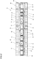
- FIG. 2 is a top view of the bus bar module according to the present embodiment.
- the bus bar module 10 includes a case 20 and a bus bar 50.
- the bus bar module 10 connects the battery sets BS of the single cells 3 in series.
- the case 20 is integrally formed of, for example, a synthetic resin or the like, and includes a plurality of bus bar housing portions 21.
- the bus bar housing portions 21 are arranged in two rows along an arrangement direction of the plurality of single cells 3.
- the bus bar housing portion 21 is formed of a frame including a peripheral wall portion 22, and the bus bar 50 is housed in the bus bar housing portion 21.
- the case 20 includes two support beam portions 24 along the arrangement of the bus bar housing portions 21, and the bus bar housing portions 21 are connected to and supported by the support beam portions 24, respectively.
- the two support beam portions 24 are connected in parallel by bridge portions 25.
- One of the support beam portions 24 is provided with an electric wire routing groove portion 31.
- the electric wire routing groove portion 31 is formed in a gutter shape with an upper side thereof opened.
- a thermistor mounting portion 28 is formed at an end of the other support beam portion 24, and a thermistor (not illustrated) configured to detect a temperature of the single cell 3 is mounted on the thermistor mounting portion 28.
- the bridge portion 25 connecting the support beam portions 24 is provided with a gutter-shaped electric wire routing groove portion 32 whose upper side is opened, and the electric wire routing groove portion 32 is provided continuously with the electric wire routing groove portion 31.
- the bus bar housing portion 21 and the thermistor mounting portion 28 are provided continuously with gutter-shaped electric wire routing groove portions 33 whose upper sides are opened.
- the electric wire routing groove portion 33 provided continuously with the bus bar housing portion 21 in one row is provided continuously with the electric wire routing groove portion 31 of the one of support beam portions 24, and the electric wire routing groove portion 33 provided continuously with the bus bar housing portion 21 in the other row and the thermistor mounting portion 28 is provided continuously with the electric wire routing groove portion 32 of the bridge portion 25.
- the electric wire routing groove portions 31, 32, 33 of the case 20 house an electric wire (not illustrated) for voltage detection electrically connected to the bus bar 50 and an electric wire (not illustrated) extending from the thermistor. These electric wires are led out from an end of the electric wire routing groove portion 31 of the one of the support beam portions 24, and are connected to a circuit board (not illustrated) including a voltage monitoring circuit and a temperature monitoring circuit.
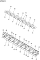
- FIG. 3 is a perspective view of a bus bar housing portion and a bus bar.
- FIG. 4 is a cross-sectional view of the bus bar module that is fastened and assembled to an electrode of a single cell of the battery assembly by a nut.
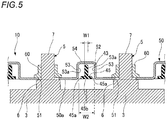
- FIG. 5 is a schematic cross-sectional view of the bus bar module that is fastened and assembled to the electrode of the single cell of the battery assembly.
- the bus bar 50 housed in the bus bar housing portion 21 of the case 20 is formed to be long.
- the bus bar 50 is formed by punching and bending a conductive metal plate.
- the bus bar 50 is formed with a plurality of fastening holes 51 as electrical connection portions. These fastening holes 51 are formed at the same pitch as a pitch of the electrodes 5 along the arrangement direction of the single cells 3 of the battery assembly 1.
- the fastening hole 51 has an inner diameter slightly larger than an outer diameter of the pole post 7 of the electrode 5.
- the pole posts 7 of the electrodes 5 are inserted through the fastening holes 51.
- the nut 60 is screwed and fastened to the pole post 7 of the electrode 5 passed through the fastening hole 51 of the bus bar 50. Accordingly, an edge of the fastening hole 51 in the bus bar 50 is fastened (fixed) while being interposed between the seat plate portion 6 of the electrode 5 and the nut 60, and the bus bar 50 and the electrode 5 are electrically connected.
- the bus bar 50 includes a projection 52 between the adjacent fastening holes 51.
- the projection 52 is formed in a convex shape protruding upward, and includes a pair of side plate portions 53 facing each other and an upper plate portion 54 provided continuously with upper edges of the side plate portions 53.
- the bus bar housing portion 21 formed of the frame that houses the bus bar 50 includes a pair of long side portions 41 and a pair of short side portions 42, and the short side portion 42 is provided continuously with both ends of the long side portion 41.
- the bus bar housing portion 21 includes a plurality of support portions 43.
- the support portions 43 are integrally formed being bridged over the long side portions 41, and are provided at intervals in a longitudinal direction of the bus bar housing portion 21.
- the support portion 43 is formed in a plate shape, and an upper edge thereof is formed in an arc shape as viewed in cross section.
- the support portion 43 extends in a direction orthogonal to an arrangement direction of the fastening holes 51 of the bus bar 50 housed in the bus bar housing portion 21.
- the support portion 43 is erected on a base portion 45 formed in a plate shape.
- the base portion 45 is formed integrally at a lower edge of the support portion 43 while protruding to both sides.
- the support portion 43 is formed narrower than the base portion 45.
- a width W1 of the support portion 43 is smaller than an interval W2 between inner side surfaces of the side plate portions 53 of the projection 52 formed on the bus bar 50.
- the support portion 43 is provided inside the projection 52 of the bus bar 50 substantially below a center of the projection 52 in a state in which the bus bar 50 is housed in the bus bar housing portion 21 from above.
- the support portion 43 abuts against a back surface of the upper plate portion 54 of the projection 52 to support the bus bar 50.
- the base portion 45 enters the inside of the projection 52.
- the bottom surface 45b opposite to a protruding side of the projection 52 is provided at an upper side, which is the protruding side of the projection 52, with respect to a lower surface 50a of the bus bar 50 on a side that is fastened to the electrode 5.
- both side surfaces 45a of the base portion 45 of the support portion 43 overlaps inner side surfaces 53a of the projection 52 as viewed from a direction orthogonal to a direction in which the bus bar 50 is fastened to the electrode 5.
- the bus bar housing portion 21 includes a plurality of locking claws 46 on the long side portion 41.
- a periphery of the bus bar 50 is locked by the locking claws 46. Accordingly, the bus bar 50 is prevented from falling out of the bus bar housing portion 21 in a state in which the projection 52 of the bus bar 50 is supported by the support portion 43.
- the bus bar module 10 In order to assemble the bus bar module 10 having the above-described structure to the battery assembly 1, the bus bar module 10 is placed on the upper part of the battery assembly 1, and the pole post 7 of the electrode 5 of the single cell 3 is inserted into the fastening hole 51 of the bus bar 50.
- the nut 60 is screwed and fastened to the pole post 7 of the electrode 5 inserted into the fastening hole 51 of the bus bar 50.
- the edge of the fastening hole 51 in the bus bar 50 is interposed between the seat plate portion 6 of the electrode 5 and the nut 60, and the bus bar 50 and the electrode 5 are electrically connected.
- the support portion 43 of the case 20 may be displaced relative to the bus bar 50.
- the side surface 45a of the base portion 45 formed in the support portion 43 abuts against the inner side surface 53a of the side plate portion 53 of the projection 52 of the bus bar 50, so that excessive displacement can be prevented.
- a flat bus bar 50A not including the projection 52 is fastened to the electrode 5 of the single cell 3, and the lower surface 50a of the bus bar 50 is supported by a plate-shaped support portion 43A between the fastening holes 51.
- the bus bar module 10 according to the present embodiment is assembled to the battery assembly 1, even if the support portion 43 of the case 20 is displaced relative to the bus bar 50, as described above, the side surface 45a of the base portion 45 of the support portion 43 abuts against the inner side surface 53a of the projection 52 of the bus bar 50, so that the excessive displacement can be prevented (see FIG. 6 ). Accordingly, the bus bar 50 can be smoothly and stably fastened to the electrode 5 of the single cell 3 by the nut 60, and good connection reliability can be attained.
- the base portion 45 enters the inside of the projection 52, and the bottom surface 45b opposite to the protruding side of the projection 52 is provided at the protruding side of the projection 52 with respect to the lower surface 50a of the bus bar 50 housed in the bus bar housing portion 21 on the side that is fastened to the electrode 5. Therefore, when the support portion 43 of the case 20 is displaced relative to the bus bar 50, the entire side surface 45a of the base portion 45 can reliably abut against the inner side surface 53a of the projection 52 of the bus bar 50, so that the excessive displacement can be prevented.
- the excessive displacement relative to the bus bar 50 can be reliably prevented by the base portions 45 of the respective support portions 43 configured to support the projections 52 between the three or more fastening holes 51.
- the present invention is not limited to the above-described embodiment, and may be appropriately modified, improved, or the like.
- materials, shapes, sizes, numbers, arrangement positions, and the like of components in the above-described embodiment are optional as long as the present invention can be achieved, and the present invention is not limited thereto.
- the fastening holes 51 are formed as a plurality of electrical connection portions configured to electrically connect and fix the plurality of electrodes 5 of the single cells 3, and the nut 60 is screwed to be fastened and fixed to the pole post 7 of the electrode 5 passed through the fastening hole 51.
- the electrical connection portion of the bus bar according to the present invention is not limited thereto, and may be a welded portion that is fixed to the electrode by welding.
Landscapes
- Chemical & Material Sciences (AREA)
- Chemical Kinetics & Catalysis (AREA)
- Electrochemistry (AREA)
- General Chemical & Material Sciences (AREA)
- Inorganic Chemistry (AREA)
- Connection Of Batteries Or Terminals (AREA)
- Battery Mounting, Suspending (AREA)
Abstract
Description
- The present invention relates to a bus bar module.
- For example, a power supply device mounted on various vehicles which are an electric automobile that travels using an electric motor, a hybrid automobile that travels using an engine and an electric motor in combination, and the like includes a bus bar module including a bus bar connected to electrodes of a plurality of single cells of a battery assembly and a case that houses the bus bar and guides a routing path of an electric wire extending from the bus bar or the like (for example, see Patent Literature 1). The bus bar of the bus bar module is supported from below by a plate-shaped support portion provided in the case, and is fastened to the electrode of each single cell using a nut.
- Patent Literature 1:
JP-A-2011-65863 - When the bus bar module is assembled to the battery assembly, if a position of the support portion of the case is shifted with respect to the bus bar and the support of the bus bar becomes unstable, workability of fastening the bus bar to the electrode of the single cell is reduced. If the support portion is largely shifted with respect to the bus bar, the support portion may enter a part of the bus bar that is fastened to the electrode of the single cell, and a fastening state may become unstable.
- The present invention has been made in view of the above-described circumstances. An aspect of the present invention provides a bus bar module in which a bus bar can be smoothly and stably fixed and electrically connected to an electrode of a single cell of a battery assembly.
- In order to achieve the above-described aspect, a bus bar module according to the present invention is characterized by the following (1) to (3).
- (1) A bus bar module including:
- a case that is assembled to a battery assembly formed of a plurality of single cells; and
- a bus bar that is supported by the case and that is formed of a conductive metal plate electrically connected to an electrode of the single cell of the battery assembly,
- in which the bus bar includes:
- a plurality of electrical connection portions configured to electrically connect and fix a plurality of the electrodes of the single cell; and
- a plurality of projections that are formed between the electrical connection portions and protrude in a direction away from the single cell,
- in which the case includes:
- a bus bar housing portion in which the bus bar is housed; and
- a support portion that is disposed in the projection of the bus bar housed in the bus bar housing portion and abuts against a back surface of the projection to support the bus bar, and
- in which the support portion includes a base portion protruding in an arrangement direction of the electrical connection portions, and at least a part of both side surfaces of the base portion overlaps with an inner side surface of the projection as viewed from a direction orthogonal to a connection direction in which the bus bar is connected and fixed to the electrode.
- (2) The bus bar module according to (1),
in which the base portion enters an inside of the projection, and a bottom surface of the projection opposite to a protruding surface of the projection is disposed at an upper side which is the protruding side of the projection with respect to a lower surface of the bus bar on a side that is connected and fixed to the electrode. - (3) The bus bar module according to (1) or (2),
in which, in the bus bar, three or more electrical connection portions are formed at equal intervals, and the projections are formed between the electrical connection portions, respectively, and
in which the case includes the support portion corresponding to each of the projections of the bus bar housed in the bus bar housing portion. - When the bus bar module having the above-described configuration (1) is assembled to the battery assembly, even if the support portion of the case is displaced relative to the bus bar, at least a part of the side surface of the base portion of the support portion abuts against the inner side surface of the projection of the bus bar, so that excessive displacement can be prevented. Accordingly, the electrical connection portion of the bus bar can be smoothly and stably fixed to the electrode of the single cell, and good connection reliability can be attained.
- According to the bus bar module having the configuration (2), when the support portion of the case is displaced relative to the bus bar, the entire side surface of the base portion can reliably abut against the inner side surface of the projection of the bus bar, so that the excessive displacement can be prevented.
- According to the bus bar module having the configuration (3), the excessive displacement relative to the bus bar can be reliably prevented by the base portions of the respective support portions configured to support the projections between the three or more electrical connection portions.
- According to the present invention, it is possible to provide a bus bar module in which a bus bar can be smoothly and stably fixed and electrically connected to an electrode of a single cell of a battery assembly.
- The present invention has been briefly described as above. Details of the present invention will be further clarified by reading a mode (hereinafter, referred to as an "embodiment") for carrying out the present invention described below with reference to the accompanying drawings.
-
-
FIG. 1 is a perspective view of a bus bar module and a battery assembly according to an embodiment. -
FIG. 2 is a top view of the bus bar module according to the present embodiment. -
FIG. 3 is a perspective view of a bus bar housing portion and a bus bar. -
FIG. 4 is a cross-sectional view of the bus bar module that is fastened and assembled to an electrode of a single cell of the battery assembly by a nut. -
FIG. 5 is a schematic cross-sectional view of the bus bar module that is fastened and assembled to the electrode of the single cell of the battery assembly. -
FIG. 6 is a schematic cross-sectional view of the bus bar module illustrating a state in which a position of a support portion of a case has been displaced relative to the bus bar. -
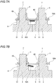
FIGS. 7A and 7B illustrate a reference example, in whichFIG. 7A is a schematic cross-sectional view of a bus bar module, andFIG. 7B is a schematic cross-sectional view of the bus bar module in a state in which a position of a support portion of a case has been displaced relative to a bus bar. - Hereinafter, an embodiment of the present invention will be described with reference to the drawings.
-
FIG. 1 is a perspective view of a bus bar module and a battery assembly according to the present embodiment. - As illustrated in
FIG. 1 , thebus bar module 10 according to the present embodiment is assembled to an upper part of a battery assembly 1 to form apower supply device 2. Thepower supply device 2 is mounted and used on various vehicles which are an electric automobile that travels using an electric motor, a hybrid automobile that travels using an engine and an electric motor in combination, and the like, and is configured to supply power to the electric motor. - The battery assembly 1 includes a plurality of
single cells 3 that are arranged in a row along one direction and are fixed to one another. Eachsingle cell 3 includes a rectangular parallelepiped battery body 4, and a pair ofelectrodes 5 protruding from near one end of an upper surface of the battery body 4 and from near the other end of the upper surface. One of the pair ofelectrodes 5 is a positive electrode and the other is a negative electrode. - The
single cells 3 are arranged such that the battery bodies 4 are in contact with one another. In the battery assembly 1, poles of theelectrodes 5 are aligned for every foursingle cells 3 adjacent to one another, and one battery set BS is formed of the foursingle cells 3 in which the poles of theelectrode 5 are aligned. In this example, the battery assembly 1 includes four battery sets BS each including foursingle cells 3, and the battery sets BS of thesingle cells 3 that are adjacent to one another are arranged such that the poles of theelectrodes 5 are alternated. - Each of the pair of
electrodes 5 is formed of a conductive metal. Theelectrode 5 includes a plate-shapedseat plate portion 6 and acolumnar pole post 7 erected at a center of theseat plate portion 6. A male screw is formed on an outer periphery of thepole post 7, and a nut 60 (described below) is fastened thereto. -
FIG. 2 is a top view of the bus bar module according to the present embodiment. - As illustrated in
FIG. 2 , thebus bar module 10 includes acase 20 and abus bar 50. Thebus bar module 10 connects the battery sets BS of thesingle cells 3 in series. - The
case 20 is integrally formed of, for example, a synthetic resin or the like, and includes a plurality of busbar housing portions 21. - The bus
bar housing portions 21 are arranged in two rows along an arrangement direction of the plurality ofsingle cells 3. The busbar housing portion 21 is formed of a frame including aperipheral wall portion 22, and thebus bar 50 is housed in the busbar housing portion 21. - The
case 20 includes twosupport beam portions 24 along the arrangement of the busbar housing portions 21, and the busbar housing portions 21 are connected to and supported by thesupport beam portions 24, respectively. The twosupport beam portions 24 are connected in parallel bybridge portions 25. - One of the
support beam portions 24 is provided with an electric wirerouting groove portion 31. The electric wirerouting groove portion 31 is formed in a gutter shape with an upper side thereof opened. Athermistor mounting portion 28 is formed at an end of the othersupport beam portion 24, and a thermistor (not illustrated) configured to detect a temperature of thesingle cell 3 is mounted on thethermistor mounting portion 28. - The
bridge portion 25 connecting thesupport beam portions 24 is provided with a gutter-shaped electric wirerouting groove portion 32 whose upper side is opened, and the electric wirerouting groove portion 32 is provided continuously with the electric wirerouting groove portion 31. - The bus
bar housing portion 21 and thethermistor mounting portion 28 are provided continuously with gutter-shaped electric wirerouting groove portions 33 whose upper sides are opened. The electric wirerouting groove portion 33 provided continuously with the busbar housing portion 21 in one row is provided continuously with the electric wirerouting groove portion 31 of the one ofsupport beam portions 24, and the electric wirerouting groove portion 33 provided continuously with the busbar housing portion 21 in the other row and thethermistor mounting portion 28 is provided continuously with the electric wirerouting groove portion 32 of thebridge portion 25. - The electric wire
routing groove portions case 20 house an electric wire (not illustrated) for voltage detection electrically connected to thebus bar 50 and an electric wire (not illustrated) extending from the thermistor. These electric wires are led out from an end of the electric wirerouting groove portion 31 of the one of thesupport beam portions 24, and are connected to a circuit board (not illustrated) including a voltage monitoring circuit and a temperature monitoring circuit. -
FIG. 3 is a perspective view of a bus bar housing portion and a bus bar.FIG. 4 is a cross-sectional view of the bus bar module that is fastened and assembled to an electrode of a single cell of the battery assembly by a nut.FIG. 5 is a schematic cross-sectional view of the bus bar module that is fastened and assembled to the electrode of the single cell of the battery assembly. - As illustrated in
FIGS. 3 to 5 , thebus bar 50 housed in the busbar housing portion 21 of thecase 20 is formed to be long. Thebus bar 50 is formed by punching and bending a conductive metal plate. Thebus bar 50 is formed with a plurality of fastening holes 51 as electrical connection portions. These fastening holes 51 are formed at the same pitch as a pitch of theelectrodes 5 along the arrangement direction of thesingle cells 3 of the battery assembly 1. Thefastening hole 51 has an inner diameter slightly larger than an outer diameter of thepole post 7 of theelectrode 5. The pole posts 7 of theelectrodes 5 are inserted through the fastening holes 51. Thenut 60 is screwed and fastened to thepole post 7 of theelectrode 5 passed through thefastening hole 51 of thebus bar 50. Accordingly, an edge of thefastening hole 51 in thebus bar 50 is fastened (fixed) while being interposed between theseat plate portion 6 of theelectrode 5 and thenut 60, and thebus bar 50 and theelectrode 5 are electrically connected. - The
bus bar 50 includes aprojection 52 between the adjacent fastening holes 51. Theprojection 52 is formed in a convex shape protruding upward, and includes a pair ofside plate portions 53 facing each other and anupper plate portion 54 provided continuously with upper edges of theside plate portions 53. - The bus
bar housing portion 21 formed of the frame that houses thebus bar 50 includes a pair oflong side portions 41 and a pair ofshort side portions 42, and theshort side portion 42 is provided continuously with both ends of thelong side portion 41. The busbar housing portion 21 includes a plurality ofsupport portions 43. Thesupport portions 43 are integrally formed being bridged over thelong side portions 41, and are provided at intervals in a longitudinal direction of the busbar housing portion 21. - The
support portion 43 is formed in a plate shape, and an upper edge thereof is formed in an arc shape as viewed in cross section. Thesupport portion 43 extends in a direction orthogonal to an arrangement direction of the fastening holes 51 of thebus bar 50 housed in the busbar housing portion 21. Thesupport portion 43 is erected on abase portion 45 formed in a plate shape. Thebase portion 45 is formed integrally at a lower edge of thesupport portion 43 while protruding to both sides. Thesupport portion 43 is formed narrower than thebase portion 45. A width W1 of thesupport portion 43 is smaller than an interval W2 between inner side surfaces of theside plate portions 53 of theprojection 52 formed on thebus bar 50. - The
support portion 43 is provided inside theprojection 52 of thebus bar 50 substantially below a center of theprojection 52 in a state in which thebus bar 50 is housed in the busbar housing portion 21 from above. Thesupport portion 43 abuts against a back surface of theupper plate portion 54 of theprojection 52 to support thebus bar 50. As illustrated inFIG. 5 , in the state in which thebus bar 50 is housed in the busbar housing portion 21, thebase portion 45 enters the inside of theprojection 52. Thebottom surface 45b opposite to a protruding side of theprojection 52 is provided at an upper side, which is the protruding side of theprojection 52, with respect to alower surface 50a of thebus bar 50 on a side that is fastened to theelectrode 5. Accordingly, in the state in which thebus bar 50 is housed in the busbar housing portion 21, bothside surfaces 45a of thebase portion 45 of thesupport portion 43 overlaps inner side surfaces 53a of theprojection 52 as viewed from a direction orthogonal to a direction in which thebus bar 50 is fastened to theelectrode 5. - The bus
bar housing portion 21 includes a plurality of lockingclaws 46 on thelong side portion 41. When thebus bar 50 has been housed in the busbar housing portion 21 from above, a periphery of thebus bar 50 is locked by the lockingclaws 46. Accordingly, thebus bar 50 is prevented from falling out of the busbar housing portion 21 in a state in which theprojection 52 of thebus bar 50 is supported by thesupport portion 43. - In order to assemble the
bus bar module 10 having the above-described structure to the battery assembly 1, thebus bar module 10 is placed on the upper part of the battery assembly 1, and thepole post 7 of theelectrode 5 of thesingle cell 3 is inserted into thefastening hole 51 of thebus bar 50. - Next, the
nut 60 is screwed and fastened to thepole post 7 of theelectrode 5 inserted into thefastening hole 51 of thebus bar 50. - Accordingly, the edge of the
fastening hole 51 in thebus bar 50 is interposed between theseat plate portion 6 of theelectrode 5 and thenut 60, and thebus bar 50 and theelectrode 5 are electrically connected. - When the
bus bar module 10 is assembled to the battery assembly 1, thesupport portion 43 of thecase 20 may be displaced relative to thebus bar 50. - However, in the
bus bar module 10 according to the present embodiment, as illustrated inFIG. 6 , theside surface 45a of thebase portion 45 formed in thesupport portion 43 abuts against theinner side surface 53a of theside plate portion 53 of theprojection 52 of thebus bar 50, so that excessive displacement can be prevented. - Here, as illustrated in
FIG. 7A , aflat bus bar 50A not including theprojection 52 is fastened to theelectrode 5 of thesingle cell 3, and thelower surface 50a of thebus bar 50 is supported by a plate-shapedsupport portion 43A between the fastening holes 51. - In this structure, when the
support portion 43A is displaced relative to thebus bar 50A in a plane direction, the displacement cannot be prevented. Therefore, as illustrated inFIG. 7B , when the displacement is large, an edge of thesupport portion 43A enters a fastening part between thebus bar 50 and theseat plate portion 6 of theelectrode 5, and a fastening state may become unstable. - On the other hand, when the
bus bar module 10 according to the present embodiment is assembled to the battery assembly 1, even if thesupport portion 43 of thecase 20 is displaced relative to thebus bar 50, as described above, theside surface 45a of thebase portion 45 of thesupport portion 43 abuts against theinner side surface 53a of theprojection 52 of thebus bar 50, so that the excessive displacement can be prevented (seeFIG. 6 ). Accordingly, thebus bar 50 can be smoothly and stably fastened to theelectrode 5 of thesingle cell 3 by thenut 60, and good connection reliability can be attained. - In addition, the
base portion 45 enters the inside of theprojection 52, and thebottom surface 45b opposite to the protruding side of theprojection 52 is provided at the protruding side of theprojection 52 with respect to thelower surface 50a of thebus bar 50 housed in the busbar housing portion 21 on the side that is fastened to theelectrode 5. Therefore, when thesupport portion 43 of thecase 20 is displaced relative to thebus bar 50, theentire side surface 45a of thebase portion 45 can reliably abut against theinner side surface 53a of theprojection 52 of thebus bar 50, so that the excessive displacement can be prevented. - The excessive displacement relative to the
bus bar 50 can be reliably prevented by thebase portions 45 of therespective support portions 43 configured to support theprojections 52 between the three or more fastening holes 51. - The present invention is not limited to the above-described embodiment, and may be appropriately modified, improved, or the like. In addition, materials, shapes, sizes, numbers, arrangement positions, and the like of components in the above-described embodiment are optional as long as the present invention can be achieved, and the present invention is not limited thereto.
- For example, in the above-described
bus bar 50 according to the embodiment, a case has been described as an example in which the fastening holes 51 are formed as a plurality of electrical connection portions configured to electrically connect and fix the plurality ofelectrodes 5 of thesingle cells 3, and thenut 60 is screwed to be fastened and fixed to thepole post 7 of theelectrode 5 passed through thefastening hole 51. It is needless to say that the electrical connection portion of the bus bar according to the present invention is not limited thereto, and may be a welded portion that is fixed to the electrode by welding. - Here, characteristics of the embodiment of the bus bar module according to the present invention described above are summarized briefly in the following [1] to [3], respectively.
- [1] A bus bar module including:
- a case (20) that is assembled to a battery assembly (1) formed of a plurality of single cells (3); and
- a bus bar (50) that is supported by the case (20), and that is formed of a conductive metal plate electrically connected to an electrode (5) of the single cell (3) of the battery assembly (1),
- in which the bus bar (50) includes:
- a plurality of electrical connection portions (fastening holes 51) configured to electrically connect and fix a plurality of the electrodes (5) of the single cell (3); and
- a plurality of projections (52) that are formed between the electrical connection portions (the fastening holes 51) and protrude in a direction away from the single cell (3),
- in which the case (20) includes:
- a bus bar housing portion (21) in which the bus bar (50) is housed; and
- a support portion (43) that is provided in the projection (52) of the bus bar (50) housed in the bus bar housing portion (21) and abuts against a back surface of the projection (52) to support the bus bar (50), and
- in which the support portion (43) includes a base portion (45) protruding in an arrangement direction of the electrical connection portions (the fastening holes 51), and at least a part of both side surfaces (45a) of the base portion (45) overlaps with an inner side surface (53a) of the projection (52) as viewed from a direction orthogonal to a direction in which the bus bar (50) is connected and fixed to the electrode (5).
- [2] The bus bar module according to [1],
in which the base portion (45) enters an inside of the projection (52), and a surface (abottom surface 45b) opposite to a protruding surface of the projection (52) is provided at the protruding side of the projection (52) with respect to a surface (alower surface 50a) of the bus bar (50) on a side that is connected and fixed to the electrode (5). - [3] The bus bar module according to [1] or [2],
in which, in the bus bar (50), three or more electrical connection portions (the fastening holes 51) are formed at equal intervals, and the projections (52) are formed between the electrical connection portions (the fastening holes 51), respectively, and
in which the case (20) includes the support portion (43) corresponding to each of the projections (52) of the bus bar (50) housed in the bus bar housing portion (21).
Claims (3)
- A bus bar module comprising:a case that is assembled to a battery assembly formed of a plurality of single cells; anda bus bar that is supported by the case and that is formed of a conductive metal plate electrically connected to an electrode of the single cell of the battery assembly,wherein the bus bar includes:a plurality of electrical connection portions configured to electrically connect and fix a plurality of the electrodes of the single cell; anda plurality of projections that are formed between the electrical connection portions and protrude in a direction away from the single cell,wherein the case includes:a bus bar housing portion in which the bus bar is housed; anda support portion that is disposed in the projection of the bus bar housed in the bus bar housing portion and abuts against a back surface of the projection to support the bus bar, andwherein the support portion includes a base portion protruding in an arrangement direction of the electrical connection portions, and at least a part of both side surfaces of the base portion overlaps with an inner side surface of the projection as viewed from a direction perpendicular to a connecting direction in which the bus bar is connected and fixed to the electrode.
- The bus bar module according to claim 1,
wherein the base portion enters an inside of the projection, and a bottom surface of the projection opposite to a protruding surface of the projection is disposed at an upper side which is the protruding side of the projection with respect to a lower surface of the bus bar on a side that is connected and fixed to the electrode. - The bus bar module according to claim 1 or 2,
wherein three or more electrical connection portions are formed at equal intervals in the bus bar, and the projections are formed between the electrical connection portions in the bus bar, respectively, and
wherein the case includes the support portion corresponding to each of the projections of the bus bar housed in the bus bar housing portion.
Applications Claiming Priority (1)
| Application Number | Priority Date | Filing Date | Title |
|---|---|---|---|
| JP2019112849A JP7132179B2 (en) | 2019-06-18 | 2019-06-18 | busbar module |
Publications (2)
| Publication Number | Publication Date |
|---|---|
| EP3754747A1 true EP3754747A1 (en) | 2020-12-23 |
| EP3754747B1 EP3754747B1 (en) | 2023-04-12 |
Family
ID=71105374
Family Applications (1)
| Application Number | Title | Priority Date | Filing Date |
|---|---|---|---|
| EP20180498.6A Active EP3754747B1 (en) | 2019-06-18 | 2020-06-17 | Bus bar module |
Country Status (4)
| Country | Link |
|---|---|
| US (1) | US11424515B2 (en) |
| EP (1) | EP3754747B1 (en) |
| JP (1) | JP7132179B2 (en) |
| CN (1) | CN112103452B (en) |
Families Citing this family (1)
| Publication number | Priority date | Publication date | Assignee | Title |
|---|---|---|---|---|
| US20210249739A1 (en) * | 2020-02-06 | 2021-08-12 | Samsung Sdi Co., Ltd. | Cell connection unit for a battery module |
Citations (4)
| Publication number | Priority date | Publication date | Assignee | Title |
|---|---|---|---|---|
| JPH07130353A (en) * | 1993-11-05 | 1995-05-19 | Yazaki Corp | Battery connection terminal cover |
| US20040043663A1 (en) * | 2002-08-30 | 2004-03-04 | Yazaki Corporation | Battery connecting plate, and attachment structure of the same |
| JP2011065863A (en) | 2009-09-17 | 2011-03-31 | Yazaki Corp | Wire arrangement body, busbar module and power supply unit |
| EP2461392A2 (en) * | 2010-11-05 | 2012-06-06 | SB LiMotive Co., Ltd. | Battery module |
Family Cites Families (6)
| Publication number | Priority date | Publication date | Assignee | Title |
|---|---|---|---|---|
| JP5537111B2 (en) * | 2009-09-30 | 2014-07-02 | 株式会社東芝 | Secondary battery device |
| KR101688488B1 (en) * | 2013-09-17 | 2016-12-21 | 삼성에스디아이 주식회사 | Battery module |
| JP6327072B2 (en) * | 2014-09-03 | 2018-05-23 | 株式会社豊田自動織機 | Battery module |
| JP6685760B2 (en) * | 2016-02-19 | 2020-04-22 | 株式会社Gsユアサ | Power storage device |
| JP6696398B2 (en) * | 2016-10-13 | 2020-05-20 | トヨタ自動車株式会社 | In-vehicle battery module |
| EP3379608B1 (en) * | 2017-03-23 | 2020-04-22 | TE Connectivity Germany GmbH | Connection assembly for a traction battery in particular for electric vehicles |
-
2019
- 2019-06-18 JP JP2019112849A patent/JP7132179B2/en active Active
-
2020
- 2020-06-11 US US16/899,569 patent/US11424515B2/en active Active
- 2020-06-17 EP EP20180498.6A patent/EP3754747B1/en active Active
- 2020-06-17 CN CN202010552385.8A patent/CN112103452B/en active Active
Patent Citations (4)
| Publication number | Priority date | Publication date | Assignee | Title |
|---|---|---|---|---|
| JPH07130353A (en) * | 1993-11-05 | 1995-05-19 | Yazaki Corp | Battery connection terminal cover |
| US20040043663A1 (en) * | 2002-08-30 | 2004-03-04 | Yazaki Corporation | Battery connecting plate, and attachment structure of the same |
| JP2011065863A (en) | 2009-09-17 | 2011-03-31 | Yazaki Corp | Wire arrangement body, busbar module and power supply unit |
| EP2461392A2 (en) * | 2010-11-05 | 2012-06-06 | SB LiMotive Co., Ltd. | Battery module |
Also Published As
| Publication number | Publication date |
|---|---|
| JP7132179B2 (en) | 2022-09-06 |
| US20200403207A1 (en) | 2020-12-24 |
| US11424515B2 (en) | 2022-08-23 |
| CN112103452A (en) | 2020-12-18 |
| CN112103452B (en) | 2022-12-13 |
| JP2020205185A (en) | 2020-12-24 |
| EP3754747B1 (en) | 2023-04-12 |
Similar Documents
| Publication | Publication Date | Title |
|---|---|---|
| US9871361B2 (en) | Busbar holding structure | |
| JP6679282B2 (en) | Holding structure for voltage detection terminals | |
| US9287672B2 (en) | Battery wiring module including a wire routing space disposed on a lid covering a bus bar | |
| US9564661B2 (en) | Battery module and wiring module | |
| JP6587598B2 (en) | Voltage detection terminal holding structure | |
| US20230411800A1 (en) | Battery module having improved wire bonding connection structure between bus bar plate and icb assembly, and battery pack including the same | |
| US9859545B2 (en) | Power supply device | |
| CN103548178B (en) | Battery interconnect module | |
| JP7256079B2 (en) | Electric wire holding structure and busbar module | |
| US11532856B2 (en) | Electric wire holding structure and bus bar module | |
| WO2013069756A1 (en) | Wiring module | |
| JP2021111502A (en) | Busbar module | |
| CN110048070A (en) | Link block cover and link block | |
| WO2017195546A1 (en) | Connection module | |
| JP2021136162A (en) | Bus bar module | |
| EP3754746B1 (en) | Bus bar module | |
| EP3754747B1 (en) | Bus bar module | |
| KR101822879B1 (en) | Secondary battery module | |
| JP2021136163A (en) | Busbar module |
Legal Events
| Date | Code | Title | Description |
|---|---|---|---|
| PUAI | Public reference made under article 153(3) epc to a published international application that has entered the european phase |
Free format text: ORIGINAL CODE: 0009012 |
|
| STAA | Information on the status of an ep patent application or granted ep patent |
Free format text: STATUS: REQUEST FOR EXAMINATION WAS MADE |
|
| 17P | Request for examination filed |
Effective date: 20200617 |
|
| AK | Designated contracting states |
Kind code of ref document: A1 Designated state(s): AL AT BE BG CH CY CZ DE DK EE ES FI FR GB GR HR HU IE IS IT LI LT LU LV MC MK MT NL NO PL PT RO RS SE SI SK SM TR |
|
| AX | Request for extension of the european patent |
Extension state: BA ME |
|
| STAA | Information on the status of an ep patent application or granted ep patent |
Free format text: STATUS: EXAMINATION IS IN PROGRESS |
|
| 17Q | First examination report despatched |
Effective date: 20220301 |
|
| REG | Reference to a national code |
Ref country code: DE Ref legal event code: R079 Ipc: H01M0050200000 Ref country code: DE Ref legal event code: R079 Ref document number: 602020009621 Country of ref document: DE Free format text: PREVIOUS MAIN CLASS: H01M0002100000 Ipc: H01M0050200000 |
|
| RIC1 | Information provided on ipc code assigned before grant |
Ipc: H01M 50/507 20210101ALI20221124BHEP Ipc: H01M 50/524 20210101ALI20221124BHEP Ipc: H01M 50/522 20210101ALI20221124BHEP Ipc: H01M 50/517 20210101ALI20221124BHEP Ipc: H01M 50/51 20210101ALI20221124BHEP Ipc: H01M 50/20 20210101AFI20221124BHEP |
|
| GRAP | Despatch of communication of intention to grant a patent |
Free format text: ORIGINAL CODE: EPIDOSNIGR1 |
|
| STAA | Information on the status of an ep patent application or granted ep patent |
Free format text: STATUS: GRANT OF PATENT IS INTENDED |
|
| INTG | Intention to grant announced |
Effective date: 20230124 |
|
| GRAS | Grant fee paid |
Free format text: ORIGINAL CODE: EPIDOSNIGR3 |
|
| GRAA | (expected) grant |
Free format text: ORIGINAL CODE: 0009210 |
|
| STAA | Information on the status of an ep patent application or granted ep patent |
Free format text: STATUS: THE PATENT HAS BEEN GRANTED |
|
| AK | Designated contracting states |
Kind code of ref document: B1 Designated state(s): AL AT BE BG CH CY CZ DE DK EE ES FI FR GB GR HR HU IE IS IT LI LT LU LV MC MK MT NL NO PL PT RO RS SE SI SK SM TR |
|
| REG | Reference to a national code |
Ref country code: GB Ref legal event code: FG4D |
|
| REG | Reference to a national code |
Ref country code: CH Ref legal event code: EP |
|
| REG | Reference to a national code |
Ref country code: DE Ref legal event code: R096 Ref document number: 602020009621 Country of ref document: DE |
|
| REG | Reference to a national code |
Ref country code: IE Ref legal event code: FG4D |
|
| REG | Reference to a national code |
Ref country code: AT Ref legal event code: REF Ref document number: 1560300 Country of ref document: AT Kind code of ref document: T Effective date: 20230515 |
|
| RAP4 | Party data changed (patent owner data changed or rights of a patent transferred) |
Owner name: YAZAKI CORPORATION |
|
| PGFP | Annual fee paid to national office [announced via postgrant information from national office to epo] |
Ref country code: DE Payment date: 20230516 Year of fee payment: 4 |
|
| REG | Reference to a national code |
Ref country code: LT Ref legal event code: MG9D |
|
| REG | Reference to a national code |
Ref country code: NL Ref legal event code: MP Effective date: 20230412 |
|
| REG | Reference to a national code |
Ref country code: AT Ref legal event code: MK05 Ref document number: 1560300 Country of ref document: AT Kind code of ref document: T Effective date: 20230412 |
|
| PG25 | Lapsed in a contracting state [announced via postgrant information from national office to epo] |
Ref country code: NL Free format text: LAPSE BECAUSE OF FAILURE TO SUBMIT A TRANSLATION OF THE DESCRIPTION OR TO PAY THE FEE WITHIN THE PRESCRIBED TIME-LIMIT Effective date: 20230412 |
|
| PG25 | Lapsed in a contracting state [announced via postgrant information from national office to epo] |
Ref country code: SE Free format text: LAPSE BECAUSE OF FAILURE TO SUBMIT A TRANSLATION OF THE DESCRIPTION OR TO PAY THE FEE WITHIN THE PRESCRIBED TIME-LIMIT Effective date: 20230412 Ref country code: PT Free format text: LAPSE BECAUSE OF FAILURE TO SUBMIT A TRANSLATION OF THE DESCRIPTION OR TO PAY THE FEE WITHIN THE PRESCRIBED TIME-LIMIT Effective date: 20230814 Ref country code: NO Free format text: LAPSE BECAUSE OF FAILURE TO SUBMIT A TRANSLATION OF THE DESCRIPTION OR TO PAY THE FEE WITHIN THE PRESCRIBED TIME-LIMIT Effective date: 20230712 Ref country code: ES Free format text: LAPSE BECAUSE OF FAILURE TO SUBMIT A TRANSLATION OF THE DESCRIPTION OR TO PAY THE FEE WITHIN THE PRESCRIBED TIME-LIMIT Effective date: 20230412 Ref country code: AT Free format text: LAPSE BECAUSE OF FAILURE TO SUBMIT A TRANSLATION OF THE DESCRIPTION OR TO PAY THE FEE WITHIN THE PRESCRIBED TIME-LIMIT Effective date: 20230412 |
|
| PG25 | Lapsed in a contracting state [announced via postgrant information from national office to epo] |
Ref country code: RS Free format text: LAPSE BECAUSE OF FAILURE TO SUBMIT A TRANSLATION OF THE DESCRIPTION OR TO PAY THE FEE WITHIN THE PRESCRIBED TIME-LIMIT Effective date: 20230412 Ref country code: PL Free format text: LAPSE BECAUSE OF FAILURE TO SUBMIT A TRANSLATION OF THE DESCRIPTION OR TO PAY THE FEE WITHIN THE PRESCRIBED TIME-LIMIT Effective date: 20230412 Ref country code: LV Free format text: LAPSE BECAUSE OF FAILURE TO SUBMIT A TRANSLATION OF THE DESCRIPTION OR TO PAY THE FEE WITHIN THE PRESCRIBED TIME-LIMIT Effective date: 20230412 Ref country code: LT Free format text: LAPSE BECAUSE OF FAILURE TO SUBMIT A TRANSLATION OF THE DESCRIPTION OR TO PAY THE FEE WITHIN THE PRESCRIBED TIME-LIMIT Effective date: 20230412 Ref country code: IS Free format text: LAPSE BECAUSE OF FAILURE TO SUBMIT A TRANSLATION OF THE DESCRIPTION OR TO PAY THE FEE WITHIN THE PRESCRIBED TIME-LIMIT Effective date: 20230812 Ref country code: HR Free format text: LAPSE BECAUSE OF FAILURE TO SUBMIT A TRANSLATION OF THE DESCRIPTION OR TO PAY THE FEE WITHIN THE PRESCRIBED TIME-LIMIT Effective date: 20230412 Ref country code: GR Free format text: LAPSE BECAUSE OF FAILURE TO SUBMIT A TRANSLATION OF THE DESCRIPTION OR TO PAY THE FEE WITHIN THE PRESCRIBED TIME-LIMIT Effective date: 20230713 Ref country code: AL Free format text: LAPSE BECAUSE OF FAILURE TO SUBMIT A TRANSLATION OF THE DESCRIPTION OR TO PAY THE FEE WITHIN THE PRESCRIBED TIME-LIMIT Effective date: 20230412 |
|
| PG25 | Lapsed in a contracting state [announced via postgrant information from national office to epo] |
Ref country code: FI Free format text: LAPSE BECAUSE OF FAILURE TO SUBMIT A TRANSLATION OF THE DESCRIPTION OR TO PAY THE FEE WITHIN THE PRESCRIBED TIME-LIMIT Effective date: 20230412 |
|
| REG | Reference to a national code |
Ref country code: DE Ref legal event code: R097 Ref document number: 602020009621 Country of ref document: DE |
|
| PG25 | Lapsed in a contracting state [announced via postgrant information from national office to epo] |
Ref country code: SK Free format text: LAPSE BECAUSE OF FAILURE TO SUBMIT A TRANSLATION OF THE DESCRIPTION OR TO PAY THE FEE WITHIN THE PRESCRIBED TIME-LIMIT Effective date: 20230412 |
|
| PG25 | Lapsed in a contracting state [announced via postgrant information from national office to epo] |
Ref country code: MC Free format text: LAPSE BECAUSE OF FAILURE TO SUBMIT A TRANSLATION OF THE DESCRIPTION OR TO PAY THE FEE WITHIN THE PRESCRIBED TIME-LIMIT Effective date: 20230412 |
|
| PG25 | Lapsed in a contracting state [announced via postgrant information from national office to epo] |
Ref country code: SM Free format text: LAPSE BECAUSE OF FAILURE TO SUBMIT A TRANSLATION OF THE DESCRIPTION OR TO PAY THE FEE WITHIN THE PRESCRIBED TIME-LIMIT Effective date: 20230412 Ref country code: SK Free format text: LAPSE BECAUSE OF FAILURE TO SUBMIT A TRANSLATION OF THE DESCRIPTION OR TO PAY THE FEE WITHIN THE PRESCRIBED TIME-LIMIT Effective date: 20230412 Ref country code: RO Free format text: LAPSE BECAUSE OF FAILURE TO SUBMIT A TRANSLATION OF THE DESCRIPTION OR TO PAY THE FEE WITHIN THE PRESCRIBED TIME-LIMIT Effective date: 20230412 Ref country code: MC Free format text: LAPSE BECAUSE OF FAILURE TO SUBMIT A TRANSLATION OF THE DESCRIPTION OR TO PAY THE FEE WITHIN THE PRESCRIBED TIME-LIMIT Effective date: 20230412 Ref country code: EE Free format text: LAPSE BECAUSE OF FAILURE TO SUBMIT A TRANSLATION OF THE DESCRIPTION OR TO PAY THE FEE WITHIN THE PRESCRIBED TIME-LIMIT Effective date: 20230412 Ref country code: DK Free format text: LAPSE BECAUSE OF FAILURE TO SUBMIT A TRANSLATION OF THE DESCRIPTION OR TO PAY THE FEE WITHIN THE PRESCRIBED TIME-LIMIT Effective date: 20230412 Ref country code: CZ Free format text: LAPSE BECAUSE OF FAILURE TO SUBMIT A TRANSLATION OF THE DESCRIPTION OR TO PAY THE FEE WITHIN THE PRESCRIBED TIME-LIMIT Effective date: 20230412 |
|
| REG | Reference to a national code |
Ref country code: CH Ref legal event code: PL |
|
| PLBE | No opposition filed within time limit |
Free format text: ORIGINAL CODE: 0009261 |
|
| STAA | Information on the status of an ep patent application or granted ep patent |
Free format text: STATUS: NO OPPOSITION FILED WITHIN TIME LIMIT |
|
| REG | Reference to a national code |
Ref country code: BE Ref legal event code: MM Effective date: 20230630 |
|
| PG25 | Lapsed in a contracting state [announced via postgrant information from national office to epo] |
Ref country code: LU Free format text: LAPSE BECAUSE OF NON-PAYMENT OF DUE FEES Effective date: 20230617 |
|
| 26N | No opposition filed |
Effective date: 20240115 |
|
| REG | Reference to a national code |
Ref country code: IE Ref legal event code: MM4A |
|
| PG25 | Lapsed in a contracting state [announced via postgrant information from national office to epo] |
Ref country code: LU Free format text: LAPSE BECAUSE OF NON-PAYMENT OF DUE FEES Effective date: 20230617 |
|
| PG25 | Lapsed in a contracting state [announced via postgrant information from national office to epo] |
Ref country code: IE Free format text: LAPSE BECAUSE OF NON-PAYMENT OF DUE FEES Effective date: 20230617 |
|
| PG25 | Lapsed in a contracting state [announced via postgrant information from national office to epo] |
Ref country code: IE Free format text: LAPSE BECAUSE OF NON-PAYMENT OF DUE FEES Effective date: 20230617 Ref country code: CH Free format text: LAPSE BECAUSE OF NON-PAYMENT OF DUE FEES Effective date: 20230630 |
|
| PG25 | Lapsed in a contracting state [announced via postgrant information from national office to epo] |
Ref country code: SI Free format text: LAPSE BECAUSE OF FAILURE TO SUBMIT A TRANSLATION OF THE DESCRIPTION OR TO PAY THE FEE WITHIN THE PRESCRIBED TIME-LIMIT Effective date: 20230412 |
|
| PG25 | Lapsed in a contracting state [announced via postgrant information from national office to epo] |
Ref country code: SI Free format text: LAPSE BECAUSE OF FAILURE TO SUBMIT A TRANSLATION OF THE DESCRIPTION OR TO PAY THE FEE WITHIN THE PRESCRIBED TIME-LIMIT Effective date: 20230412 Ref country code: IT Free format text: LAPSE BECAUSE OF FAILURE TO SUBMIT A TRANSLATION OF THE DESCRIPTION OR TO PAY THE FEE WITHIN THE PRESCRIBED TIME-LIMIT Effective date: 20230412 Ref country code: FR Free format text: LAPSE BECAUSE OF NON-PAYMENT OF DUE FEES Effective date: 20230630 Ref country code: BE Free format text: LAPSE BECAUSE OF NON-PAYMENT OF DUE FEES Effective date: 20230630 |
|
| PG25 | Lapsed in a contracting state [announced via postgrant information from national office to epo] |
Ref country code: BG Free format text: LAPSE BECAUSE OF FAILURE TO SUBMIT A TRANSLATION OF THE DESCRIPTION OR TO PAY THE FEE WITHIN THE PRESCRIBED TIME-LIMIT Effective date: 20230412 |
|
| PG25 | Lapsed in a contracting state [announced via postgrant information from national office to epo] |
Ref country code: BG Free format text: LAPSE BECAUSE OF FAILURE TO SUBMIT A TRANSLATION OF THE DESCRIPTION OR TO PAY THE FEE WITHIN THE PRESCRIBED TIME-LIMIT Effective date: 20230412 |
|
| REG | Reference to a national code |
Ref country code: DE Ref legal event code: R119 Ref document number: 602020009621 Country of ref document: DE |
|
| GBPC | Gb: european patent ceased through non-payment of renewal fee |
Effective date: 20240617 |
|
| PG25 | Lapsed in a contracting state [announced via postgrant information from national office to epo] |
Ref country code: DE Free format text: LAPSE BECAUSE OF NON-PAYMENT OF DUE FEES Effective date: 20250101 |
|
| PG25 | Lapsed in a contracting state [announced via postgrant information from national office to epo] |
Ref country code: GB Free format text: LAPSE BECAUSE OF NON-PAYMENT OF DUE FEES Effective date: 20240617 |
|
| PG25 | Lapsed in a contracting state [announced via postgrant information from national office to epo] |
Ref country code: CY Free format text: LAPSE BECAUSE OF FAILURE TO SUBMIT A TRANSLATION OF THE DESCRIPTION OR TO PAY THE FEE WITHIN THE PRESCRIBED TIME-LIMIT; INVALID AB INITIO Effective date: 20200617 |
|
| PG25 | Lapsed in a contracting state [announced via postgrant information from national office to epo] |
Ref country code: HU Free format text: LAPSE BECAUSE OF FAILURE TO SUBMIT A TRANSLATION OF THE DESCRIPTION OR TO PAY THE FEE WITHIN THE PRESCRIBED TIME-LIMIT; INVALID AB INITIO Effective date: 20200617 |
|
| PG25 | Lapsed in a contracting state [announced via postgrant information from national office to epo] |
Ref country code: TR Free format text: LAPSE BECAUSE OF FAILURE TO SUBMIT A TRANSLATION OF THE DESCRIPTION OR TO PAY THE FEE WITHIN THE PRESCRIBED TIME-LIMIT Effective date: 20230412 |