EP3754618B1 - Recording control device, recording control system, recording control method, and recording control program - Google Patents
Recording control device, recording control system, recording control method, and recording control program Download PDFInfo
- Publication number
- EP3754618B1 EP3754618B1 EP19898647.3A EP19898647A EP3754618B1 EP 3754618 B1 EP3754618 B1 EP 3754618B1 EP 19898647 A EP19898647 A EP 19898647A EP 3754618 B1 EP3754618 B1 EP 3754618B1
- Authority
- EP
- European Patent Office
- Prior art keywords
- vehicle
- person
- captured data
- unit
- recording
- Prior art date
- Legal status (The legal status is an assumption and is not a legal conclusion. Google has not performed a legal analysis and makes no representation as to the accuracy of the status listed.)
- Active
Links
Images


Classifications
-
- G—PHYSICS
- G07—CHECKING-DEVICES
- G07C—TIME OR ATTENDANCE REGISTERS; REGISTERING OR INDICATING THE WORKING OF MACHINES; GENERATING RANDOM NUMBERS; VOTING OR LOTTERY APPARATUS; ARRANGEMENTS, SYSTEMS OR APPARATUS FOR CHECKING NOT PROVIDED FOR ELSEWHERE
- G07C5/00—Registering or indicating the working of vehicles
- G07C5/08—Registering or indicating performance data other than driving, working, idle, or waiting time, with or without registering driving, working, idle or waiting time
- G07C5/0841—Registering performance data
- G07C5/085—Registering performance data using electronic data carriers
- G07C5/0866—Registering performance data using electronic data carriers the electronic data carrier being a digital video recorder in combination with video camera
-
- H—ELECTRICITY
- H04—ELECTRIC COMMUNICATION TECHNIQUE
- H04N—PICTORIAL COMMUNICATION, e.g. TELEVISION
- H04N5/00—Details of television systems
- H04N5/76—Television signal recording
- H04N5/765—Interface circuits between an apparatus for recording and another apparatus
- H04N5/77—Interface circuits between an apparatus for recording and another apparatus between a recording apparatus and a television camera
-
- G—PHYSICS
- G06—COMPUTING OR CALCULATING; COUNTING
- G06T—IMAGE DATA PROCESSING OR GENERATION, IN GENERAL
- G06T7/00—Image analysis
- G06T7/20—Analysis of motion
-
- G—PHYSICS
- G06—COMPUTING OR CALCULATING; COUNTING
- G06T—IMAGE DATA PROCESSING OR GENERATION, IN GENERAL
- G06T7/00—Image analysis
- G06T7/70—Determining position or orientation of objects or cameras
-
- G—PHYSICS
- G06—COMPUTING OR CALCULATING; COUNTING
- G06V—IMAGE OR VIDEO RECOGNITION OR UNDERSTANDING
- G06V20/00—Scenes; Scene-specific elements
- G06V20/50—Context or environment of the image
- G06V20/52—Surveillance or monitoring of activities, e.g. for recognising suspicious objects
-
- G—PHYSICS
- G06—COMPUTING OR CALCULATING; COUNTING
- G06V—IMAGE OR VIDEO RECOGNITION OR UNDERSTANDING
- G06V20/00—Scenes; Scene-specific elements
- G06V20/50—Context or environment of the image
- G06V20/56—Context or environment of the image exterior to a vehicle by using sensors mounted on the vehicle
-
- G—PHYSICS
- G06—COMPUTING OR CALCULATING; COUNTING
- G06V—IMAGE OR VIDEO RECOGNITION OR UNDERSTANDING
- G06V40/00—Recognition of biometric, human-related or animal-related patterns in image or video data
- G06V40/10—Human or animal bodies, e.g. vehicle occupants or pedestrians; Body parts, e.g. hands
-
- G—PHYSICS
- G06—COMPUTING OR CALCULATING; COUNTING
- G06V—IMAGE OR VIDEO RECOGNITION OR UNDERSTANDING
- G06V40/00—Recognition of biometric, human-related or animal-related patterns in image or video data
- G06V40/10—Human or animal bodies, e.g. vehicle occupants or pedestrians; Body parts, e.g. hands
- G06V40/103—Static body considered as a whole, e.g. static pedestrian or occupant recognition
-
- G—PHYSICS
- G06—COMPUTING OR CALCULATING; COUNTING
- G06V—IMAGE OR VIDEO RECOGNITION OR UNDERSTANDING
- G06V40/00—Recognition of biometric, human-related or animal-related patterns in image or video data
- G06V40/10—Human or animal bodies, e.g. vehicle occupants or pedestrians; Body parts, e.g. hands
- G06V40/16—Human faces, e.g. facial parts, sketches or expressions
- G06V40/161—Detection; Localisation; Normalisation
-
- G—PHYSICS
- G06—COMPUTING OR CALCULATING; COUNTING
- G06V—IMAGE OR VIDEO RECOGNITION OR UNDERSTANDING
- G06V40/00—Recognition of biometric, human-related or animal-related patterns in image or video data
- G06V40/20—Movements or behaviour, e.g. gesture recognition
-
- G—PHYSICS
- G08—SIGNALLING
- G08B—SIGNALLING SYSTEMS, e.g. PERSONAL CALLING SYSTEMS; ORDER TELEGRAPHS; ALARM SYSTEMS
- G08B13/00—Burglar, theft or intruder alarms
- G08B13/18—Actuation by interference with heat, light, or radiation of shorter wavelength; Actuation by intruding sources of heat, light, or radiation of shorter wavelength
- G08B13/189—Actuation by interference with heat, light, or radiation of shorter wavelength; Actuation by intruding sources of heat, light, or radiation of shorter wavelength using passive radiation detection systems
- G08B13/194—Actuation by interference with heat, light, or radiation of shorter wavelength; Actuation by intruding sources of heat, light, or radiation of shorter wavelength using passive radiation detection systems using image scanning and comparing systems
- G08B13/196—Actuation by interference with heat, light, or radiation of shorter wavelength; Actuation by intruding sources of heat, light, or radiation of shorter wavelength using passive radiation detection systems using image scanning and comparing systems using television cameras
- G08B13/19602—Image analysis to detect motion of the intruder, e.g. by frame subtraction
- G08B13/19613—Recognition of a predetermined image pattern or behaviour pattern indicating theft or intrusion
-
- G—PHYSICS
- G08—SIGNALLING
- G08B—SIGNALLING SYSTEMS, e.g. PERSONAL CALLING SYSTEMS; ORDER TELEGRAPHS; ALARM SYSTEMS
- G08B13/00—Burglar, theft or intruder alarms
- G08B13/18—Actuation by interference with heat, light, or radiation of shorter wavelength; Actuation by intruding sources of heat, light, or radiation of shorter wavelength
- G08B13/189—Actuation by interference with heat, light, or radiation of shorter wavelength; Actuation by intruding sources of heat, light, or radiation of shorter wavelength using passive radiation detection systems
- G08B13/194—Actuation by interference with heat, light, or radiation of shorter wavelength; Actuation by intruding sources of heat, light, or radiation of shorter wavelength using passive radiation detection systems using image scanning and comparing systems
- G08B13/196—Actuation by interference with heat, light, or radiation of shorter wavelength; Actuation by intruding sources of heat, light, or radiation of shorter wavelength using passive radiation detection systems using image scanning and comparing systems using television cameras
- G08B13/19639—Details of the system layout
- G08B13/19647—Systems specially adapted for intrusion detection in or around a vehicle
-
- H—ELECTRICITY
- H04—ELECTRIC COMMUNICATION TECHNIQUE
- H04N—PICTORIAL COMMUNICATION, e.g. TELEVISION
- H04N7/00—Television systems
- H04N7/18—Closed-circuit television [CCTV] systems, i.e. systems in which the video signal is not broadcast
- H04N7/183—Closed-circuit television [CCTV] systems, i.e. systems in which the video signal is not broadcast for receiving images from a single remote source
-
- B—PERFORMING OPERATIONS; TRANSPORTING
- B60—VEHICLES IN GENERAL
- B60R—VEHICLES, VEHICLE FITTINGS, OR VEHICLE PARTS, NOT OTHERWISE PROVIDED FOR
- B60R25/00—Fittings or systems for preventing or indicating unauthorised use or theft of vehicles
- B60R25/10—Fittings or systems for preventing or indicating unauthorised use or theft of vehicles actuating a signalling device
- B60R25/1004—Alarm systems characterised by the type of sensor, e.g. current sensing means
- B60R25/1012—Zone surveillance means, e.g. parking lots, truck depots
-
- G—PHYSICS
- G06—COMPUTING OR CALCULATING; COUNTING
- G06T—IMAGE DATA PROCESSING OR GENERATION, IN GENERAL
- G06T2207/00—Indexing scheme for image analysis or image enhancement
- G06T2207/10—Image acquisition modality
- G06T2207/10016—Video; Image sequence
-
- G—PHYSICS
- G06—COMPUTING OR CALCULATING; COUNTING
- G06T—IMAGE DATA PROCESSING OR GENERATION, IN GENERAL
- G06T2207/00—Indexing scheme for image analysis or image enhancement
- G06T2207/30—Subject of image; Context of image processing
- G06T2207/30196—Human being; Person
- G06T2207/30201—Face
-
- G—PHYSICS
- G06—COMPUTING OR CALCULATING; COUNTING
- G06T—IMAGE DATA PROCESSING OR GENERATION, IN GENERAL
- G06T2207/00—Indexing scheme for image analysis or image enhancement
- G06T2207/30—Subject of image; Context of image processing
- G06T2207/30248—Vehicle exterior or interior
- G06T2207/30252—Vehicle exterior; Vicinity of vehicle
- G06T2207/30264—Parking
-
- G—PHYSICS
- G08—SIGNALLING
- G08B—SIGNALLING SYSTEMS, e.g. PERSONAL CALLING SYSTEMS; ORDER TELEGRAPHS; ALARM SYSTEMS
- G08B13/00—Burglar, theft or intruder alarms
- G08B13/18—Actuation by interference with heat, light, or radiation of shorter wavelength; Actuation by intruding sources of heat, light, or radiation of shorter wavelength
- G08B13/189—Actuation by interference with heat, light, or radiation of shorter wavelength; Actuation by intruding sources of heat, light, or radiation of shorter wavelength using passive radiation detection systems
- G08B13/194—Actuation by interference with heat, light, or radiation of shorter wavelength; Actuation by intruding sources of heat, light, or radiation of shorter wavelength using passive radiation detection systems using image scanning and comparing systems
- G08B13/196—Actuation by interference with heat, light, or radiation of shorter wavelength; Actuation by intruding sources of heat, light, or radiation of shorter wavelength using passive radiation detection systems using image scanning and comparing systems using television cameras
- G08B13/19665—Details related to the storage of video surveillance data
- G08B13/19669—Event triggers storage or change of storage policy
Definitions
- the operation unit 50 receives various kinds of operation performed on the recording control system 1.
- the various kinds of operation include operation of starting to replay the event recording data, operation of starting to store the event recording data, and the like.
- the operation unit 50 outputs an operation signal corresponding to the received operation to an operation control unit 127.
- the operation unit 50 may be realized by, for example, a physical button or a touch panel arranged in the display unit 60.
- the control unit 100 includes the captured data acquisition unit 120, a buffer memory 121, a captured data processing unit 122, a recording control unit 123, a replay control unit 124, a CAN information acquisition unit 125, a vehicle positional information determination unit 126, the operation control unit 127, a display control unit 128, the event detection unit 129, the positional information acquisition unit 130, a parking detection unit 131, and a video processing unit 132. All of the units included in the control unit 100 are connected to one another via a bus 110.
- the control unit 100 may be realized by, for example, an electronic circuit including a central processing unit (CPU).
- the captured data processing unit 122 outputs the generated captured data to the recording control unit 123. Further, the captured data processing unit 122 outputs the generated captured data to the display control unit 128.
- a time period for which the captured data is generated as the file is assumed as 60 seconds as one example, but embodiments are not limited to this example.
- the recording control unit 123 records, as overwritable captured data, the captured data that is generated as the file by the captured data processing unit 122 in the recording unit 20, during a time period in which the event detection unit 129 does not detect an event. If a recording capacity of the recording unit 20 becomes full, the recording control unit 123 records, in an overwriting manner, new captured data in a recording area in which a piece of old captured data is recorded among pieces of the overwritable captured data recorded in the recording unit 20, for example.
- the operation control unit 127 receives, from the operation unit 50, an operation signal related to operation that is received from a user or the like. For example, the operation control unit 127 receives an operation signal related to operation of starting to replay the event recording data, operation of starting to store the event recording data, or the like. The operation control unit 127 outputs a control signal corresponding to the received operation signal to the recording control unit 123 or the replay control unit 124. In this case, the recording control unit 123 and the replay control unit 124 perform operation in accordance with the control signal.
- the event detection unit 129 detects, as acceleration corresponding to the event, acceleration corresponding to acceleration at the time the vehicle collides with a different object, such as a different vehicle, among acceleration output by the sensor 70. Detection of the acceleration corresponding to the event may be performed by adding a weight in each of an x-axis direction, a y-axis direction, and a z-axis direction in the sensor 70 that is a three-axis acceleration sensor. Further, detection of the acceleration corresponding to the event may be performed by using, as a detection target, acceleration that increases rapidly.
- the parking detection unit 131 detects that the vehicle is parked. For example, the parking detection unit 131 receives the vehicle information from the CAN information acquisition unit 125. The parking detection unit 131 detects, from the vehicle information, conditions, such as turning off of power, such as an engine, of the vehicle, turning off of accessory power, selection of a parking gear, operation of a parking brake, or a current location of the vehicle indicating a parking lot. The parking detection unit 131 may detect a combination of various conditions. The parking detection unit 131 detects that the vehicle is parked on the basis of the detected condition.
- conditions such as turning off of power, such as an engine, of the vehicle, turning off of accessory power, selection of a parking gear, operation of a parking brake, or a current location of the vehicle indicating a parking lot.
- the parking detection unit 131 may detect a combination of various conditions.
- the parking detection unit 131 detects that the vehicle is parked on the basis of the detected condition.
- FIG. 2 is a schematic diagram for explaining the range in which the target object is to be detected.
- FIG. 2 an example of a case in which a target object is detected using a camera that captures a video of an entire circumferential area of a vehicle M is illustrated.
- the vehicle M is a vehicle on which the recording control system 1 is mounted.
- the video processing unit 132 detects a specific target object located in a range 200 from the vehicle M in the captured data.
- the range 200 is a range relatively close to the vehicle M, and is a range within, for example, 1 to 2 meters from the vehicle M, but embodiments are not limited to this example.
- the control unit 100 detects an event based on output from the sensor 70 and stores the event recording data when an event occurs.
- the control unit 100 detects an event based on a detection result obtained by the moving object detection unit 1321 and stores the event recording data when an event occurs.
- the control unit 100 may also detect an event based on output from the sensor 70, in addition to detecting an event based on the detection result obtained by the moving object detection unit 1321.
- the control unit 100 detects an event and stores the event recording data by operating as a parking monitoring mode while the vehicle is parked.
- control unit 100 Upon entering the parking monitoring mode, the control unit 100 starts to detect a moving object around the vehicle.
- Step S105 If the moving object detected within the predetermined distance is not a person (No at Step S105), the control unit 100 proceeds to Step S109. In contrast, if the moving object detected within the predetermined distance is a person (Yes at Step S105), the control unit 100 proceeds to Step S106.
- the communication control unit 133 transmits various kinds of information to outside via the communication unit 90.
- the communication control unit 133 transmits the event recording data to the cloud server or the like.
- the communication control unit 133 may transmit the event recording data to a public agency, such as a police.
- FIG. 10 is a flowchart illustrating an example of the flow of the process of alerting a police by the control unit 100A. Meanwhile, the flowchart in FIG. 10 indicates a process to be performed after Step S107 illustrated in FIG. 7 .
Landscapes
- Engineering & Computer Science (AREA)
- Multimedia (AREA)
- Physics & Mathematics (AREA)
- General Physics & Mathematics (AREA)
- Theoretical Computer Science (AREA)
- Human Computer Interaction (AREA)
- Computer Vision & Pattern Recognition (AREA)
- Health & Medical Sciences (AREA)
- General Health & Medical Sciences (AREA)
- Signal Processing (AREA)
- Psychiatry (AREA)
- Social Psychology (AREA)
- Oral & Maxillofacial Surgery (AREA)
- Traffic Control Systems (AREA)
- Time Recorders, Dirve Recorders, Access Control (AREA)
- Closed-Circuit Television Systems (AREA)
Description
- The present invention relates to a recording control device, a recording control system, a recording control method, and a recording control program.
- A technology for recording a video of a moving object when the moving object is detected around a parked vehicle has been known (for example,
JP 2006-321357 A -
JP2011090645A -
JP2006259828 A - When parking recording is being performed by moving object detection during parking, and if a road exists in a capturing direction and vehicles or persons pass through the road, the vehicles or the persons that have passed through the road are detected as moving objects. In this case, a large amount of unnecessary event recording data may be stored, and a capacity of a recording device may be fully used.
- An object of the present invention is to provide a recording device, a recording control system, a recording control method, and a recording control program capable of recording an appropriate event.
- In accordance with the present invention, a recording control device, a recording control method, and a recording control program as set forth in the appended claims is provided. In particular, a recording control device according to the present invention comprising: a captured data acquisition unit configured to acquire captured data from a camera that captures a video of surroundings of a vehicle; a parking detection unit configured to detect that the vehicle is parked; a moving object detection unit configured to detect a moving object from captured data that is acquired by the captured data acquisition unit while the vehicle is parked; a person recognition unit configured to recognize that the moving object detected by the moving object detection unit is a person; a behavior detection unit configured to detect that the person recognized by the person recognition unit is performing a specific behavior at a certain distance shorter than a predetermined distance from the vehicle; and a recording control unit configured to store the captured data as event recording data if it is detected that the person is performing the specific behavior.
- A recording control system according to the present invention comprising: the recording control device according to the present invention; a camera configured to capture a video of surroundings of the vehicle; and a recording unit configured to record the captured data.
- A recording control method according to the present invention comprising: a captured data acquisition step of acquiring captured data from a camera that captures a video of surroundings of a vehicle; a parking detection step of detecting that the vehicle is parked; a moving object detection step of detecting a moving object from captured data that is acquired at the captured data acquisition step while the vehicle is parked; a person recognition step of recognizing that the moving object detected at the moving object detection step is a person; a behavior detection step of detecting that the person recognized at the person recognition step is performing a specific behavior at a certain distance shorter than a predetermined distance from the vehicle; and a recording control step of storing the captured data as event recording data if it is detected that the person is performing the specific behavior.
- A recording control program according to the present invention that causes a computer to execute: a captured data acquisition step of acquiring captured data from a camera that captures a video of surroundings of a vehicle; a parking detection step of detecting that the vehicle is parked; a moving object detection step of detecting a moving object from captured data that is acquired at the captured data acquisition step while the vehicle is parked; a person recognition step of recognizing that the moving object detected at the moving object detection step is a person; a behavior detection step of detecting that the person recognized at the person recognition step is performing a specific behavior at a certain distance shorter than a predetermined distance from the vehicle; and a recording control step of storing the captured data as event recording data if it is detected that the person is performing the specific behavior. Advantageous Effects of Invention
- According to the present invention, it is possible to record an appropriate event.
-
-
FIG. 1 is a block diagram illustrating an example of a configuration of a recording control system according to a first embodiment. -
FIG. 2 is a schematic diagram for explaining a range in which a target object is to be detected. -
FIG. 3 is a schematic diagram for explaining the range in which the target object is to be detected. -
FIG. 4 is a schematic diagram illustrating an example of captured data. -
FIG. 5 is a schematic diagram for explaining a method of storing event recording data. -
FIG. 6 is a schematic diagram for explaining the method of storing the event recording data. -
FIG. 7 is a flowchart illustrating an example of the flow of a process performed by a recording control device according to the first embodiment. -
FIG. 8 is a flowchart illustrating an example of the flow of the process performed by the recording control device according to the first embodiment. -
FIG. 9 is a block diagram illustrating an example of a configuration of a recording control system according to a second embodiment. -
FIG. 10 is a flowchart illustrating an example of a process performed by the recording control system according to the second embodiment. - Embodiments of the present invention will be described in detail below with reference to the accompanying drawings. The present invention is not limited to the embodiments below, and in a case where a plurality of embodiments is provided, the present invention includes a configuration obtained by combining the embodiments.
- With reference to
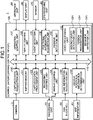
FIG. 1 , a configuration of a recording control system according to a first embodiment will be described.FIG. 1 is a block diagram illustrating an example of the configuration of the recording control system according to the first embodiment. - As illustrated in
FIG. 1 , arecording control system 1 includes acamera 10, arecording unit 20, a controller area network (CAN)interface 30, anoperation unit 50, adisplay unit 60, asensor 70, aGPS receiving unit 80, and a control unit (recording control device) 100. Therecording control system 1 is used in a vehicle and detects a person who is performing a specific behavior at a certain distance shorter than a predetermined distance from the vehicle on the basis of captured data that is captured during parking. Then, if a person who is performing a specific behavior is detected, therecording control system 1 starts to record the captured data. - The
recording control system 1 is what is called a drive recorder that is mounted in, for example, an upper part of a windshield of the vehicle in an orientation in which a video of the front of the vehicle can be captured, detects a shock corresponding to an incident that needs to be detected as an event, such as an accident, and stores, as event recording data, captured data corresponding to a time period including a time of occurrence of the accident. Therecording control system 1 is not limited to a device that is mounted as a stand-alone device on the vehicle, but may be implemented by a configuration that is realized as a function of a navigation device, a configuration that is equipped in the vehicle in advance, or a portable device that is used by being placed on the vehicle. - The
camera 10 captures a video of surroundings of the vehicle on which therecording control system 1 is mounted. For example, thecamera 10 may be one or a combination of a camera that captures a video of surroundings in front of the vehicle, a camera that captures a video of surroundings in the rear of the vehicle, and a camera that captures videos of surroundings on lateral sides of the vehicle, may be a camera unit including a plurality of cameras for capturing videos of surroundings of the vehicle, or may be a spherical camera. Thecamera 10 outputs captured data obtained by capturing a video of surroundings of the vehicle to a captureddata acquisition unit 120. - The
recording unit 20 records various kinds of data, such as event recording data, that is recorded upon detection of an event. For example, therecording unit 20 records captured data of a person who has performed a specific behavior at a certain distance shorter than a predetermined distance from the vehicle. For example, therecording unit 20 stores, as the event recording data, captured data corresponding to a predetermined time period among pieces of captured data of the person who has performed the specific behavior at a certain distance shorter than the predetermined distance from the vehicle. Therecording unit 20 stores therein a program for implementing each of the units of thecontrol unit 100, for example. In this case, thecontrol unit 100 loads and executes the program stored in therecording unit 20, and implements functions of each of the units. Therecording unit 20 may be realized by, for example, a semiconductor memory device, such as a random access memory (RAM), a read only memory (ROM), or a flash memory, or a storage device, such as a hard disk, a solid state drive, or an optical disk. Therecording unit 20 may be constructed of a plurality of different memories or the like. - The
CAN interface 30 is an interface for acquiring various kinds of vehicle information via a CAN. The vehicle information includes, for example, information on an operating condition of an engine, a travelling condition of the vehicle, and the like. - The
operation unit 50 receives various kinds of operation performed on therecording control system 1. The various kinds of operation include operation of starting to replay the event recording data, operation of starting to store the event recording data, and the like. Theoperation unit 50 outputs an operation signal corresponding to the received operation to anoperation control unit 127. Theoperation unit 50 may be realized by, for example, a physical button or a touch panel arranged in thedisplay unit 60. - The
display unit 60 displays various videos. Thedisplay unit 60 displays, for example, the event recording data recorded in therecording unit 20. Thedisplay unit 60 is, for example, a display including a liquid crystal display (LCD), an organic electro-luminescence (EL) display, or the like. - The
sensor 70 detects various kinds of information caused by occurrence of an event on the vehicle. For example, thesensor 70 is an acceleration sensor and detects acceleration applied to the vehicle. For another example, thesensor 70 is a gyro sensor and detects information on a posture of the vehicle. Thesensor 70 outputs a detection result to anevent detection unit 129. - The
GPS receiving unit 80 is constructed of a GPS receiving circuit, a GPS receiving antenna, and the like, and receives a GPS signal. TheGPS receiving unit 80 outputs the received GPS signal to a positionalinformation acquisition unit 130. - The
control unit 100 includes the captureddata acquisition unit 120, abuffer memory 121, a captureddata processing unit 122, arecording control unit 123, areplay control unit 124, a CANinformation acquisition unit 125, a vehicle positionalinformation determination unit 126, theoperation control unit 127, adisplay control unit 128, theevent detection unit 129, the positionalinformation acquisition unit 130, aparking detection unit 131, and avideo processing unit 132. All of the units included in thecontrol unit 100 are connected to one another via abus 110. Thecontrol unit 100 may be realized by, for example, an electronic circuit including a central processing unit (CPU). - The captured
data acquisition unit 120 acquires various kinds of captured data from outside. For example, the captureddata acquisition unit 120 acquires captured data that is captured by thecamera 10. For example, the captureddata acquisition unit 120 outputs the captured data acquired from thecamera 10 to thebuffer memory 121 and thedisplay control unit 128. The captureddata acquisition unit 120 may acquire, as the captured data, video data that is captured by thecamera 10, or may acquire captured data including voice data that is acquired by a microphone (not illustrated) arranged in thecamera 10 or at a different position, in addition to the video data. - The
buffer memory 121 is an internal memory of thecontrol unit 100 for temporarily storing the captured data acquired by the captureddata acquisition unit 120. Specifically, thebuffer memory 121 temporarily stores therein captured data corresponding to a predetermined time period acquired by the captureddata acquisition unit 120, while updating the captured data. - The captured
data processing unit 122 performs various processes on the captured data that is temporarily stored in thebuffer memory 121. The captureddata processing unit 122 converts the captured data that is temporarily stored in thebuffer memory 121 into an arbitrary file format, such as an MP4 format, that is encoded by a codec in an arbitrary format, such as H.264 or Moving Picture Experts Group (MPEG)-4. For example, the captureddata processing unit 122 generates captured data as a file corresponding to a predetermined time period, from the captured data that is temporarily stored in thebuffer memory 121. Specifically, for example, the captureddata processing unit 122 generates, as a file, captured data corresponding to 60 seconds in recording order, from the captured data that is temporarily stored in thebuffer memory 121. The captureddata processing unit 122 outputs the generated captured data to therecording control unit 123. Further, the captureddata processing unit 122 outputs the generated captured data to thedisplay control unit 128. A time period for which the captured data is generated as the file is assumed as 60 seconds as one example, but embodiments are not limited to this example. - The
recording control unit 123 records various kinds of data in therecording unit 20. For example, therecording control unit 123 causes therecording unit 20 to record the captured data that is generated as the file by the captureddata processing unit 122. - Specifically, in a case in which recording is continuously performed, the
recording control unit 123 records, as overwritable captured data, the captured data that is generated as the file by the captureddata processing unit 122 in therecording unit 20, during a time period in which theevent detection unit 129 does not detect an event. If a recording capacity of therecording unit 20 becomes full, therecording control unit 123 records, in an overwriting manner, new captured data in a recording area in which a piece of old captured data is recorded among pieces of the overwritable captured data recorded in therecording unit 20, for example. If theevent detection unit 129 determines that an event has occurred, therecording control unit 123 stores, in therecording unit 20, captured data corresponding to a predetermined time period before, after, and including an event detection time, as event recording data for which overwriting is inhibited. If it is detected that a parking position of the vehicle is located at a certain distance shorter than a predetermined distance from a road, that a capturing direction of thecamera 10 is oriented toward the road, and that a person is performing a specific behavior, therecording control unit 123 determines the detection as occurrence of an event and stores, as the event recording data, captured data corresponding to the predetermined time period before and after the event detection time in therecording unit 20. - In a case in which recording is not continuously performed, the
recording control unit 123 starts to perform recording from an event detection time if theevent detection unit 129 determines that an event has occurred, and stores, in therecording unit 20, captured data corresponding to a predetermined time period since the detection of the event as the event recording data for which overwriting is inhibited. - The
replay control unit 124 replays various kinds of data recorded in therecording unit 20. For example, thereplay control unit 124 replays the captured data recorded in therecording unit 20. For example, thereplay control unit 124 replays the captured data that is stored as the event recording data in therecording unit 20. Specifically, thereplay control unit 124 replays the captured data in accordance with a control signal corresponding to operation on theoperation unit 50, where the control signal is output from theoperation control unit 127. - The CAN
information acquisition unit 125 acquires various kinds of vehicle information via theCAN interface 30. - The vehicle positional
information determination unit 126 refers to mapinformation 40 with respect to a current location of the vehicle and determines a geographical condition around the vehicle. For example, the vehicle positionalinformation determination unit 126 acquires current location information from the positionalinformation acquisition unit 130. For example, the vehicle positionalinformation determination unit 126 acquires themap information 40 from an external device. Themap information 40 may be stored in, for example, therecording unit 20 or may be acquired from an external server via a communication unit (not illustrated). Specifically, the vehicle positionalinformation determination unit 126 acquires information indicating a position and an orientation of the vehicle, and determines whether a parking position of the vehicle is located at a certain distance shorter than the predetermined distance and the capturing direction of thecamera 10 is oriented toward the road, based together on themap information 40. - The
operation control unit 127 receives, from theoperation unit 50, an operation signal related to operation that is received from a user or the like. For example, theoperation control unit 127 receives an operation signal related to operation of starting to replay the event recording data, operation of starting to store the event recording data, or the like. Theoperation control unit 127 outputs a control signal corresponding to the received operation signal to therecording control unit 123 or thereplay control unit 124. In this case, therecording control unit 123 and thereplay control unit 124 perform operation in accordance with the control signal. - The
display control unit 128 displays various videos on thedisplay unit 60. Specifically, thedisplay control unit 128 outputs a video signal to thedisplay unit 60 to thereby display a video on thedisplay unit 60. For example, thedisplay control unit 128 outputs a video signal related to the event recording data replayed by thereplay control unit 124 to thedisplay unit 60, to thereby cause thedisplay unit 60 to display captured data that is stored as the event recording data. Thedisplay control unit 128 outputs a video signal related to the captured data acquired by the captureddata acquisition unit 120 to thedisplay unit 60, to thereby cause thedisplay unit 60 to display captured data being captured. - The
event detection unit 129 receives a detection result obtained by thesensor 70. Theevent detection unit 129 detects an event on the basis of the received detection result. For example, theevent detection unit 129 acquires acceleration information on acceleration as the detection result. In this case, theevent detection unit 129 detects an event based on the acceleration information. Upon detecting the event, theevent detection unit 129 outputs a control signal indicating information on the detection of the event to therecording control unit 123. In this case, therecording control unit 123 stores the captured data captured by thecamera 10 as the event recording data in therecording unit 20. - The
event detection unit 129 detects, as acceleration corresponding to the event, acceleration corresponding to acceleration at the time the vehicle collides with a different object, such as a different vehicle, among acceleration output by thesensor 70. Detection of the acceleration corresponding to the event may be performed by adding a weight in each of an x-axis direction, a y-axis direction, and a z-axis direction in thesensor 70 that is a three-axis acceleration sensor. Further, detection of the acceleration corresponding to the event may be performed by using, as a detection target, acceleration that increases rapidly. - The positional
information acquisition unit 130 receives a GPS signal from theGPS receiving unit 80. The positionalinformation acquisition unit 130 calculates the current location information on the basis of the GPS signal. The positionalinformation acquisition unit 130 outputs the current location information to the vehicle positionalinformation determination unit 126. - The
parking detection unit 131 detects that the vehicle is parked. For example, theparking detection unit 131 receives the vehicle information from the CANinformation acquisition unit 125. Theparking detection unit 131 detects, from the vehicle information, conditions, such as turning off of power, such as an engine, of the vehicle, turning off of accessory power, selection of a parking gear, operation of a parking brake, or a current location of the vehicle indicating a parking lot. Theparking detection unit 131 may detect a combination of various conditions. Theparking detection unit 131 detects that the vehicle is parked on the basis of the detected condition. - The
video processing unit 132 performs a process of detecting a specific target object from the captured data acquired by the captured data. Specifically, thevideo processing unit 132 detects a target object that is included in a specific range from the vehicle in the captured data. In the first embodiment, thevideo processing unit 132 includes a movingobject detection unit 1321, aperson recognition unit 1322, and abehavior detection unit 1323. - With reference to
FIG. 2 , a range in which the target object is to be detected will be described.FIG. 2 is a schematic diagram for explaining the range in which the target object is to be detected. InFIG. 2 , an example of a case in which a target object is detected using a camera that captures a video of an entire circumferential area of a vehicle M is illustrated. - As illustrated in
FIG. 2 , the vehicle M is a vehicle on which therecording control system 1 is mounted. In this case, thevideo processing unit 132 detects a specific target object located in arange 200 from the vehicle M in the captured data. Therange 200 is a range relatively close to the vehicle M, and is a range within, for example, 1 to 2 meters from the vehicle M, but embodiments are not limited to this example. - The
range 200 illustrated inFIG. 2 need not be fixed, but may be changed depending on conditions. - With reference to
FIG. 3 , a method of changing the range in which the target object is to be detected will be described.FIG. 3 is a schematic diagram for explaining the method of changing the range in which the target object is to be detected. Even inFIG. 3 , the example of the case in which a target object is detected using the camera that captures a video of the entire circumferential area of the vehicle M is illustrated. - In
FIG. 3 , therange 200, arange 200A, and arange 200B are illustrated. If it is desired to detect a specific target object in a narrower range than a normal range, the range in which the target object is to be detected may be reduced from therange 200 to therange 200A. Further, if it is desired to detect a specific target object in a wider range than the normal range, the range in which the target object is to be detected may be increased from therange 200 to therange 200B. - The
video processing unit 132 may change therange 200 to therange 200A or therange 200B on the basis of the vehicle positional information that is calculated by the vehicle positionalinformation determination unit 126, for example. -
FIG. 1 will be referred to again. The movingobject detection unit 1321 detects presence or absence of a moving object from the captured data acquired by the captureddata acquisition unit 120. For example, the movingobject detection unit 1321 detects a region in which luminance or color information is changed for each of frames, in units of pixels or in units of square blocks of a few pixels by a few pixels in the captured data, for example. In this case, if a temporal change is detected in a region with a predetermined size or larger, the movingobject detection unit 1321 determines that a moving object is detected. Meanwhile, a method of detecting a moving object by the movingobject detection unit 1321 is not limited to the example as described above, and it may be possible to detect a moving object using a well-known method. - The
person recognition unit 1322 recognizes a person from the captured data acquired by the captureddata acquisition unit 120. For example, theperson recognition unit 1322 detects that a moving object is a person by, for example, comparing a region constituting the moving object detected by the movingobject detection unit 1321 and a person recognition dictionary stored in a storage unit (not illustrated). Theperson recognition unit 1322 recognizes a moving person by performing a person recognition process on the moving object detected by the movingobject detection unit 1321. Theperson recognition unit 1322 detects a distance between the recognized person and the vehicle M on the basis of a lowermost position of a pixel range indicating the recognized person. Theperson recognition unit 1322 performs face recognition on the recognized person and detects an orientation of a face of the recognized person. As for the orientation of the face, for example, it is possible to determine whether the face is turned toward the vehicle M by recognizing a positional relationship among eyes, a nose, and a mouth. Theperson recognition unit 1322 determines identity of the recognized person on the basis of a feature amount of the recognized person. Theperson recognition unit 1322 may detect the distance between the person as the detected moving object and the vehicle M on the basis of a size of the face detected for the recognized person or a distance between parts of the face. - The
behavior detection unit 1323 detects that the person recognized by theperson recognition unit 1322 is performing a specific behavior at a certain distance shorter than the predetermined distance from the vehicle M, on the basis of a recognition result obtained by theperson recognition unit 1322. Thebehavior detection unit 1323 detects, as the specific behavior, a behavior in which the recognized person is turning his/her face toward the vehicle for a predetermined time period or longer, on the basis of a face recognition result of the recognized person. Here, the predetermined time period is not specifically limited, but may be a few seconds (for example, three seconds) or longer. Further, the predetermined time period may be changed in accordance with a request from a user. - The
behavior detection unit 1323 detects, as the specific behavior, a behavior in which the recognized person passes by the vehicle M multiple times in a predetermined time period, on the basis of information for identifying the recognized person. For example, thebehavior detection unit 1323 detects, as the specific behavior, a behavior in which the recognized person passes by the vehicle M twice or more in the predetermined time period, such as 10 minutes, while turning his/her face toward the vehicle M. For example, thebehavior detection unit 1323 may detect, as the specific behavior, a behavior in which the recognized person approaches while turning his/her face toward the vehicle. In other words, thebehavior detection unit 1323 detects that the recognized person looks inside the vehicle for hunting something or walks back and forth repeatedly around the vehicle M. - Processes performed by the moving
object detection unit 1321, theperson recognition unit 1322, and thebehavior detection unit 1323 will be described in detail with reference toFIG. 4. FIG. 4 is a schematic diagram illustrating an example of the captured data acquired by the captureddata acquisition unit 120. - The moving
object detection unit 1321 detects a movingobject region 310 including a moving object from captureddata 300, for example. In this case, theperson recognition unit 1322 performs a person recognition process on the movingobject region 310, and recognizes aperson 320 included in the movingobject region 310. Theperson recognition unit 1322 performs a face recognition process on theperson 320, and detects aface region 330. Theperson recognition unit 1322 detects an orientation of a face of theperson 320 on the basis of theface region 330. Then, thebehavior detection unit 1323 determines that theperson 320 is performing a specific behavior if theperson 320 is turning his/her face toward the vehicle for a predetermined time period or longer, on the basis of the orientation of the face of theperson 320 detected by theperson recognition unit 1322. - As illustrated in
FIG. 4 , if the person who is performing the specific behavior with respect to the vehicle is detected, therecording control unit 123 stores captured data corresponding to the predetermined time period as the event recording data. In other words, therecording control unit 123 regards the person who is performing the specific behavior with respect to the vehicle as a suspicious person, and stores captured data in which the person is captured as the event recording data. - During a time period in which the vehicle is operating, the
control unit 100 detects an event based on output from thesensor 70 and stores the event recording data when an event occurs. During a time period in which the vehicle is parked, thecontrol unit 100 detects an event based on a detection result obtained by the movingobject detection unit 1321 and stores the event recording data when an event occurs. During the time period in which the vehicle is parked, thecontrol unit 100 may also detect an event based on output from thesensor 70, in addition to detecting an event based on the detection result obtained by the movingobject detection unit 1321. Thecontrol unit 100 detects an event and stores the event recording data by operating as a parking monitoring mode while the vehicle is parked. - Further, in the processes described above with reference to
FIG. 4 , a predetermined person that is registered in advance may be excluded from a suspicious person detection process. Here, the predetermined person may be an owner of the vehicle, family members of the owner of the vehicle, or friends of the owner of the vehicle. The persons as described above are registered, in advance, detection excluded persons in a storage unit (not illustrated), for example. With this configuration, it is possible to exclude the registered persons from targets of the suspicious person detection process. - A method of storing the event recording data will be described with reference to
FIG. 5 andFIG. 6 .FIG. 5 is a schematic diagram for explaining a method of storing normal event recording data.FIG. 6 is a schematic diagram for explaining a method of storing event recording data in a case in which a suspicious person is detected. - As illustrated in
FIG. 5 , for example, if an event is detected at a time t0, captured data corresponding to a first period from t0-t1 to t0+t1, which is a time period before and after the time to, is stored as event recording data. The time period corresponding to the captured data that is stored as the event recording data is not specifically limited, and may be, for example, 30 seconds before and after the time at which the event is detected. The event recording data illustrated inFIG. 5 is event recording data corresponding to a collision accident, for example. - As illustrated in
FIG. 6 , for example, if a suspicious person is detected at the time to, captured data corresponding to a second period from t0-t1 to t0+t2, which is a time period before and after the time to, is stored as event recording data. Here, t2 is a time period longer than t1. In other words, if the suspicious person is detected, a time period taken after detection of the suspicious person is set to be longer than a time period taken before detection of the suspicious person. In this case, for example, a sum of 10 seconds before detection of the suspicious person and a few minutes (for example, one to two minutes) after detection of the suspicious person is stored as the event recording data. In other words, the second period is longer than the first period illustrated inFIG. 5 . Meanwhile, the time period to be stored as the event recording data is not limited to the examples as described above. - The
recording control system 1 may include a warning unit that issues a warning to theperson 320 upon detecting theperson 320 who is performing the specific behavior. In this case, therecording control system 1 may issue a warning to theperson 320 using a warning sound, or may issue a warning by voice saying "step away from the vehicle", for example. - A process performed by the control unit according to the first embodiment will be described with reference to
FIG. 7. FIG. 7 is a flowchart illustrating an example of the flow of the process performed by the control unit according to the first embodiment. - The
control unit 100, at Step S101, determines whether the vehicle is parked. For example, thecontrol unit 100 determines whether the vehicle is parked on the basis of vehicle information acquired via a CAN or the like. - At Step S101, if it is determined that the vehicle is not parked (No at Step S101), the
control unit 100 terminates the process illustrated inFIG. 7 . In this case, while the process illustrated inFIG. 7 is terminated, thecontrol unit 100 continues to detect an event by detecting acceleration because the vehicle is in a state of not being parked. In contrast, if it is determined that the vehicle is parked (Yes at Step S101), thecontrol unit 100 proceeds to Step S102. - Subsequently, the
control unit 100 enters the parking monitoring mode to capture videos of surroundings of the vehicle (Step S102). Then, thecontrol unit 100 proceeds to Step S103. - Upon entering the parking monitoring mode, the
control unit 100 starts to detect a moving object around the vehicle. - At Step S103, after starting detection of a moving object, if it is detected that a moving object is not detected (No at Step S103), the
control unit 100 proceeds to Step S109. In contrast, if it is determined that a moving object is detected (Yes at Step S103), thecontrol unit 100 proceeds to Step S104. - Subsequently, at Step S104, the
control unit 100 determines whether the detected moving object is located within a predetermined distance from the vehicle (Step S104) . - If it is determined that a distance between the detected object and the vehicle is not within the predetermined distance (No at Step S104), the
control unit 100 proceeds to Step S109. In contrast, if the distance between the detected object and the vehicle is within the predetermined distance (Yes at Step S104), thecontrol unit 100 proceeds to Step S105. - Subsequently, at Step S105, the
control unit 100 determines whether the moving object detected within the predetermined distance is a person (Step S105). - If the moving object detected within the predetermined distance is not a person (No at Step S105), the
control unit 100 proceeds to Step S109. In contrast, if the moving object detected within the predetermined distance is a person (Yes at Step S105), thecontrol unit 100 proceeds to Step S106. - Subsequently, the
control unit 100 detects a face of the moving object that is determined as the person at Step S105 (Step S106). Then, thecontrol unit 100 proceeds to Step S107. Thecontrol unit 100 may detect the distance between the person who is the detected moving object and the vehicle M on the basis of a size of the face of the person detected at Step S106 or on the basis of a distance between parts of the face. In this case, determination of the distance between the vehicle M and the moving object at Step S104 will be performed after Step S106. - Subsequently, at Step S107, the
control unit 100 determines whether the detected person's face is turned toward the vehicle. - If it is determined that the detected person's face is not turned toward the vehicle (No at Step S107), the
control unit 100 proceeds to Step S109. In contrast, if the detected person's face is turned toward the vehicle (Yes at Step S107), thecontrol unit 100 proceeds to Step S108. - Subsequently, the
control unit 100 starts to store, as the event recording data, captured data of the detected person in the recording unit 20 (Step S108). Then, thecontrol unit 100 proceeds to Step S109. - At Step S109, the
control unit 100 determines whether the parking monitoring mode is terminated. If it is determined that the parking monitoring mode is not terminated (No at Step S109), thecontrol unit 100 proceeds to Step S103. In contrast, if it is determined that the parking monitoring mode is terminated (Yes at Step S109), thecontrol unit 100 terminates the process illustrated inFIG. 7 . - A process that is different from the process illustrated in
FIG. 7 and that is performed by thecontrol unit 100 will be described with reference toFIG. 8. FIG. 8 is a flowchart illustrating an example of the flow of the process that is different from the process inFIG. 7 and that is performed by thecontrol unit 100. - Step S201 to Step S207 are the same as Step S101 to Step S107 illustrated in
FIG. 7 , and therefore, explanation thereof will be omitted. - After determination of Yes is made at Step S207, the
control unit 100 starts to issue a warning to the detected person (Step S208). Then, thecontrol unit 100 proceeds to Step S209. - Step S209 and Step S210 are the same as Step S108 and Step S109 illustrated in
FIG. 7 , and therefore, explanation thereof will be omitted. Meanwhile, thecontrol unit 100 may perform the processes at Step S208 and Step S209 in parallel. - As described above, in the first embodiment, in a case in which a person is detected within a certain distance shorter than a predetermined distance from the vehicle and the person is performing a specific behavior, captured data in which the person is captured is recorded as the event recording data. With this configuration, it is possible to prevent a capacity of a recording unit from being fully used for unnecessary captured data.
- A display control device according to a second embodiment will be described with reference to
FIG. 9. FIG. 9 is a block diagram illustrating an example of a configuration of the display control device according to the second embodiment. - As illustrated in
FIG. 9 , arecording control system 1A includes thecamera 10, therecording unit 20, theCAN interface 30, theoperation unit 50, thedisplay unit 60, thesensor 70, theGPS receiving unit 80, acommunication unit 90, and a control unit (recording control device) 100A. Thecontrol unit 100A includes the captureddata acquisition unit 120, thebuffer memory 121, the captureddata processing unit 122, therecording control unit 123, thereplay control unit 124, the CANinformation acquisition unit 125, the vehicle positionalinformation determination unit 126, theoperation control unit 127, thedisplay control unit 128, theevent detection unit 129, the positionalinformation acquisition unit 130, theparking detection unit 131, thevideo processing unit 132, and acommunication control unit 133. In other words, therecording control system 1A is different from therecording control system 1 in that therecording control system 1A includes thecommunication unit 90 and thecommunication control unit 133. - The
communication unit 90 performs information communication with external information processing devices via a wired or wireless network (not illustrated). For example, thecommunication unit 90 performs information communication between thecontrol unit 100 and a cloud server. Specifically, thecommunication unit 90 transmits the event recording data that is recorded in therecording unit 20 to the cloud server under the control of thecommunication control unit 133. Accordingly, the event recording data is stored in the cloud server. In this case, a user is able to access the event recording data recorded in the cloud server, via a terminal device of the user. Here, examples of the terminal device include a personal computer (PC), a smartphone, and a tablet terminal, but embodiments are not limited to these examples. - The
communication control unit 133 transmits various kinds of information to outside via thecommunication unit 90. For example, thecommunication control unit 133 transmits the event recording data to the cloud server or the like. For example, when theevent detection unit 129 detects a predetermined event, thecommunication control unit 133 may transmit the event recording data to a public agency, such as a police. - For example, it is assumed that the
event detection unit 129 has acquired information on predetermined acceleration or higher from thesensor 70 in a state in which a person who is performing a predetermined behavior is detected. In this case, for example, theevent detection unit 129 determines that it is necessary to transmit the event recording data to a police or the like. In this case, theevent detection unit 129 outputs, to thecommunication control unit 133, a control signal for transmitting the event recording data to a police or the like. In this case, thecommunication control unit 133 transmits the event recording data to a police or the like in accordance with the control signal received from theevent detection unit 129. - A process performed by the
control unit 100A to alert a police or the like after detecting a person who is performing a predetermined behavior will be described with reference toFIG. 10. FIG. 10 is a flowchart illustrating an example of the flow of the process of alerting a police by thecontrol unit 100A. Meanwhile, the flowchart inFIG. 10 indicates a process to be performed after Step S107 illustrated inFIG. 7 . - First, after a person who is performing a predetermined behavior has been detected, the
control unit 100A determines, at Step S301, whether predetermined acceleration or higher is detected. The acceleration to be detected at Step S301 is set to be smaller acceleration than the acceleration at which it is determined that an event has occurred due to collision of a different vehicle with the vehicle. The acceleration detected here is acceleration that occurs when a scratch is made on the vehicle, when a part is removed, or when the vehicle is broken into, for example. - If the predetermined acceleration or higher is detected (Yes at Step S301), the
control unit 100A proceeds to Step S302, alerts a police or the like by transmitting the event recording data to the police or the like, and stores the event recording data in the recording unit 20 (Step S302). At Step S302, thecontrol unit 100A may store the event recording data in the cloud server. Then, thecontrol unit 100A terminates the process illustrated inFIG. 10 . - In contrast, if the predetermined acceleration or higher is not detected (No at Step S301), the
control unit 100A stores the event recording data in the recording unit 20 (Step S303). The event recording data stored at Step S303 is the same as the data stored at Step S108 inFIG. 7 and at Step S209 inFIG. 8 . At Step S303, thecontrol unit 100A may store the event recording data in the cloud server. Then, thecontrol unit 100A terminates the process illustrated inFIG. 10 . - As described above, in the second embodiment, it is possible to store the event recording data in the cloud server or the like via the communication unit. With this configuration, in the second embodiment, it is possible to further prevent the capacity of the recording unit from being fully used for unnecessary event recording data.
- While the embodiments of the present invention have been explained above, embodiments are not limited by the contents of the above-described embodiments. Further, the constituent elements described above include one that can be easily thought of by a person skilled in the art, one that is practically identical. Furthermore, the constituent elements described above may be combined appropriately. Moreover, within the scope as defined in the appended claims, various omission, replacement, and modifications of the constituent elements may be made.
-
- 10
- camera
- 20
- recording unit
- 30
- CAN interface
- 40
- map information
- 50
- operation unit
- 60
- display unit
- 70
- sensor
- 80
- GPS receiving unit
- 90
- communication unit
- 100
- control unit (recording control device)
- 110
- bus
- 120
- captured data acquisition unit
- 121
- buffer memory
- 122
- captured data processing unit
- 123
- recording control unit
- 124
- replay control unit
- 125
- CAN information acquisition unit
- 126
- vehicle positional information determination unit
- 127
- operation control unit
- 128
- display control unit
- 129
- event detection unit
- 130
- positional information acquisition unit
- 131
- parking detection unit
- 132
- video processing unit
- 132
- video processing unit
- 1321
- moving object detection unit
- 1322
- person recognition unit
- 1323
- behavior detection unit
- 133
- communication control unit
Claims (6)
- A recording control device (100) used in a vehicle comprising:a captured data acquisition unit (120) configured to acquire captured data from a camera that captures a video of surroundings of the vehicle (S102,S202);a parking detection unit (131) configured to receive vehicle information from a vehicle controller area network (CAN) interface and detect that the vehicle is parked (S102,S202);a moving object detection unit (1321) configured to detect a moving object from captured data that is acquired by the captured data acquisition unit (120) after the parking detection unit (131) detects that the vehicle is parked (S103,S203);a person recognition unit (1322) configured to recognize, from captured data that is acquired by the captured data acquisition unit (120), that the moving object detected by the moving object detection unit (1321) is a person (S105,S205);a behavior detection unit (1323) configured to detect that the person recognized by the person recognition unit (1322) is performing a specific behavior at a certain distance shorter than a predetermined distance from the vehicle (S107,S207);a recording control unit (123) configured to store the captured data as event recording data if it is detected by the behavior detection unit (1323) that the person is performing the specific behavior (S108,S209); anda vehicle positional information determination unit (126) configured to acquire information indicating a position and an orientation of the vehicle, refer to surrounding map information with respect to a current location of the vehicle, and determine whether a parking position of the vehicle is located at a certain distance shorter than a predetermined distance from a road and a capturing direction of the camera is oriented toward the road, whereinif it is detected that the parking position of the vehicle is located at a certain distance shorter than the predetermined distance from the road, that the capturing direction of the camera is oriented toward the road, and that the person is performing the specific behavior, the recording control unit (123) is configured to store the captured data as the event recording data.
- The recording control device (100) according to claim 1, wherein the behavior detection unit (1323) is adapted to detect a face of the person and an orientation of the face, and detect, as the specific behavior, a behavior whether the person is turning the face toward the vehicle for a predetermined time period or longer (S107,S207).
- The recording control device (100) according to claims 1 or 2, wherein the behavior detection unit (1323) is adapted to detect, as the specific behavior, a behavior whether the person passes by the vehicle multiple times in a predetermined time period, on the basis of information for identifying the person (S107,S207).
- A recording control system comprising:the recording control device (100) according to any one of claims 1 to 3;a camera (10) configured to capture a video of surroundings of the vehicle (S102,S202); anda recording control unit (123) configured to record the captured data in a recording unit (20) (S108,S209).
- A recording control method used in a vehicle comprising:a captured data acquisition step (S102,S202) of acquiring captured data from a camera that captures a video of surroundings of the vehicle;a parking detection step (S102,S202) of receiving the vehicle information from a vehicle controller area network (CAN) interface and detecting that the vehicle is parked;a moving object detection step (S103,S203) of detecting a moving object from captured data that is acquired at the captured data acquisition step after the parking detection step detects that the vehicle is parked;a person recognition step (S105,S205) of recognizing, from captured data that is acquired by the captured data acquisition step, that the moving object detected at the moving object detection step is a person;a behavior detection step (S107,S207) of detecting that the person recognized at the person recognition step is performing a specific behavior at a certain distance shorter than a predetermined distance from the vehicle;a recording control step (S108,S209) of storing the captured data as event recording data if it is detected by the behavior detection step that the person is performing the specific behavior; anda vehicle positional information determination step of acquiring information indicating a position and an orientation of the vehicle, referring to surrounding map information with respect to a current location of the vehicle, and determining whether a parking position of the vehicle is located at a certain distance shorter than a predetermined distance from a road and a capturing direction of the camera is oriented toward the road, whereinif it is detected that the parking position of the vehicle is located at a certain distance shorter than the predetermined distance from the road, that the capturing direction of the camera is oriented toward the road, and that the person is performing the specific behavior, the recording control step stores the captured data as the event recording data.
- A recording control program that causes a computer used in a vehicle to execute:a captured data acquisition step (S102,S202) of acquiring captured data from a camera that captures a video of surroundings of the vehicle;a parking detection step (S102,S202) of receiving the vehicle information from a vehicle controller area network (CAN) interface and detecting that the vehicle is parked;a moving object detection step (S103,S203) of detecting a moving object from captured data that is acquired at the captured data acquisition step after the parking detection step detects that the vehicle is parked;a person recognition step (S105,S205) of recognizing, from captured data that is acquired by the captured data acquisition step, that the moving object detected at the moving object detection step is a person;a behavior detection step (S107,S207) of detecting that the person recognized at the person recognition step is performing a specific behavior at a certain distance shorter than a predetermined distance from the vehicle;a recording control step (S108,S209) of storing the captured data as event recording data if it is detected by the behavior detection step that the person is performing the specific behavior; anda vehicle positional information determination step of acquiring information indicating a position and an orientation of the vehicle, referring to surrounding map information with respect to a current location of the vehicle, and determining whether a parking position of the vehicle is located at a certain distance shorter than a predetermined distance from a road and a capturing direction of the camera is oriented toward the road, whereinif it is detected that the parking position of the vehicle is located at a certain distance shorter than the predetermined distance from the road, that the capturing direction of the camera is oriented toward the road, and that the person is performing the specific behavior, the recording control step stores the captured data as the event recording data.
Applications Claiming Priority (2)
| Application Number | Priority Date | Filing Date | Title |
|---|---|---|---|
| JP2018236920A JP6669240B1 (en) | 2018-12-19 | 2018-12-19 | Recording control device, recording control system, recording control method, and recording control program |
| PCT/JP2019/023353 WO2020129279A1 (en) | 2018-12-19 | 2019-06-12 | Recording control device, recording control system, recording control method, and recording control program |
Publications (3)
| Publication Number | Publication Date |
|---|---|
| EP3754618A1 EP3754618A1 (en) | 2020-12-23 |
| EP3754618A4 EP3754618A4 (en) | 2021-05-05 |
| EP3754618B1 true EP3754618B1 (en) | 2022-06-22 |
Family
ID=70000719
Family Applications (1)
| Application Number | Title | Priority Date | Filing Date |
|---|---|---|---|
| EP19898647.3A Active EP3754618B1 (en) | 2018-12-19 | 2019-06-12 | Recording control device, recording control system, recording control method, and recording control program |
Country Status (5)
| Country | Link |
|---|---|
| US (1) | US11265508B2 (en) |
| EP (1) | EP3754618B1 (en) |
| JP (1) | JP6669240B1 (en) |
| CN (1) | CN111656411B (en) |
| WO (1) | WO2020129279A1 (en) |
Families Citing this family (12)
| Publication number | Priority date | Publication date | Assignee | Title |
|---|---|---|---|---|
| US10726640B2 (en) * | 2016-11-15 | 2020-07-28 | At&T Mobility Ii Llc | Facilitation of smart communications hub to support driverless vehicles in 5G networks or other next generation networks |
| JP6791331B2 (en) * | 2019-03-27 | 2020-11-25 | 株式会社Jvcケンウッド | Recording control device, recording control method, and program |
| JP6828772B2 (en) * | 2019-06-27 | 2021-02-10 | 株式会社Jvcケンウッド | Recording control device, recording device, recording control method, and recording control program |
| JP7570086B2 (en) * | 2020-03-31 | 2024-10-21 | 株式会社ユピテル | Photographing device, system and program |
| KR102912859B1 (en) | 2020-06-05 | 2026-01-15 | 가부시끼가이샤 레조낙 | Binder for non-aqueous secondary battery electrodes and slurry for non-aqueous secondary battery electrodes |
| WO2022024212A1 (en) | 2020-07-28 | 2022-02-03 | 日本電気株式会社 | Image processing device, image processing method, and program |
| US11616932B1 (en) * | 2020-12-15 | 2023-03-28 | Ambarella International Lp | Car security camera triggering mechanism |
| WO2023119771A1 (en) * | 2021-12-23 | 2023-06-29 | 株式会社Jvcケンウッド | Voice command acceptance device, voice command acceptance method, and program |
| CN114979463B (en) * | 2022-04-12 | 2023-08-08 | 北京卡普拉科技有限公司 | Intelligent parking recording method, device, storage medium and equipment |
| WO2024024148A1 (en) * | 2022-07-26 | 2024-02-01 | ソニーセミコンダクタソリューションズ株式会社 | On-vehicle monitoring device, information processing device, and on-vehicle monitoring system |
| EP4439509A1 (en) * | 2023-03-27 | 2024-10-02 | Sony Group Corporation | Information processing apparatus and information processing method |
| US20260112161A1 (en) * | 2024-10-23 | 2026-04-23 | Volvo Car Corporation | System for active monitoring of vehicle surroundings |
Family Cites Families (9)
| Publication number | Priority date | Publication date | Assignee | Title |
|---|---|---|---|---|
| JP2003348569A (en) * | 2002-05-28 | 2003-12-05 | Toshiba Lighting & Technology Corp | Surveillance camera system |
| JP4702598B2 (en) * | 2005-03-15 | 2011-06-15 | オムロン株式会社 | Monitoring system, monitoring apparatus and method, recording medium, and program |
| JP2006321357A (en) | 2005-05-19 | 2006-11-30 | Auto Network Gijutsu Kenkyusho:Kk | Vehicle monitoring device |
| JP4797720B2 (en) * | 2006-03-15 | 2011-10-19 | オムロン株式会社 | Monitoring device and method, image processing device and method, and program |
| JP5316995B2 (en) * | 2009-10-26 | 2013-10-16 | 株式会社ユピテル | Vehicle recording device |
| US9809196B1 (en) * | 2011-04-22 | 2017-11-07 | Emerging Automotive, Llc | Methods and systems for vehicle security and remote access and safety control interfaces and notifications |
| US20140218529A1 (en) * | 2013-02-04 | 2014-08-07 | Magna Electronics Inc. | Vehicle data recording system |
| KR102211496B1 (en) * | 2014-05-14 | 2021-02-03 | 주식회사 인텔리빅스 | Event detection system of blackbox for vehicle and method for event detection |
| JP6383376B2 (en) * | 2016-03-31 | 2018-08-29 | 株式会社Subaru | Peripheral risk display device |
-
2018
- 2018-12-19 JP JP2018236920A patent/JP6669240B1/en active Active
-
2019
- 2019-06-12 EP EP19898647.3A patent/EP3754618B1/en active Active
- 2019-06-12 CN CN201980010267.XA patent/CN111656411B/en active Active
- 2019-06-12 WO PCT/JP2019/023353 patent/WO2020129279A1/en not_active Ceased
-
2020
- 2020-09-01 US US17/008,757 patent/US11265508B2/en active Active
Also Published As
| Publication number | Publication date |
|---|---|
| JP2020098514A (en) | 2020-06-25 |
| EP3754618A1 (en) | 2020-12-23 |
| CN111656411B (en) | 2022-04-15 |
| CN111656411A (en) | 2020-09-11 |
| EP3754618A4 (en) | 2021-05-05 |
| US11265508B2 (en) | 2022-03-01 |
| US20200396413A1 (en) | 2020-12-17 |
| JP6669240B1 (en) | 2020-03-18 |
| WO2020129279A1 (en) | 2020-06-25 |
Similar Documents
| Publication | Publication Date | Title |
|---|---|---|
| EP3754618B1 (en) | Recording control device, recording control system, recording control method, and recording control program | |
| US10523904B2 (en) | Vehicle data recording system | |
| EP2905704B1 (en) | Self-monitoring and alert system for intelligent vehicle | |
| US20140375808A1 (en) | Apparatus, method, and computer readable medium for monitoring a number of passengers in an automobile | |
| EP3361723B1 (en) | Monitoring vehicle involved in a collision | |
| US20180139485A1 (en) | Camera System for Car Security | |
| JP2020504694A (en) | System for monitoring under autonomous driving vehicles | |
| EP4216179B1 (en) | Vehicle recording control device and vehicle recording control method | |
| JP2015185064A (en) | Moving body detection system and moving body detection device | |
| WO2020194584A1 (en) | Object tracking device, control method, and program | |
| US20210188213A1 (en) | System and method for using on-vehicle sensors for security monitoring | |
| CN114347950A (en) | Vehicle abnormity processing method, vehicle-mounted equipment and electronic equipment | |
| CN117565819A (en) | Vehicle control method, device and vehicle | |
| EP4152281B1 (en) | Vehicle recording device, vehicle recording control method, and program | |
| CN112639893A (en) | Vehicle recording control device, vehicle imaging device, vehicle recording control method, and program | |
| CN118560423A (en) | Vehicle parking alarm control method, device, electronic equipment, vehicle and storage medium | |
| JP7057074B2 (en) | On-board unit and driving support device | |
| JP7255425B2 (en) | Recording control device, recording control method, and program | |
| KR101026631B1 (en) | Wireless security control system and method | |
| KR101512809B1 (en) | Black box apparatus for vehicle and controlling method thereof | |
| JP6664411B2 (en) | Security device, security control method, program, and storage medium | |
| CN117841908A (en) | A method, device, vehicle and storage medium for monitoring parking environment | |
| JP2020156064A (en) | Vehicular recording control device, vehicular recording control method and program | |
| CN101470909A (en) | Road condition recording method and electronic device | |
| JP7322422B2 (en) | Recording control device, recording control method, and program |
Legal Events
| Date | Code | Title | Description |
|---|---|---|---|
| STAA | Information on the status of an ep patent application or granted ep patent |
Free format text: STATUS: THE INTERNATIONAL PUBLICATION HAS BEEN MADE |
|
| PUAI | Public reference made under article 153(3) epc to a published international application that has entered the european phase |
Free format text: ORIGINAL CODE: 0009012 |
|
| STAA | Information on the status of an ep patent application or granted ep patent |
Free format text: STATUS: REQUEST FOR EXAMINATION WAS MADE |
|
| 17P | Request for examination filed |
Effective date: 20200914 |
|
| AK | Designated contracting states |
Kind code of ref document: A1 Designated state(s): AL AT BE BG CH CY CZ DE DK EE ES FI FR GB GR HR HU IE IS IT LI LT LU LV MC MK MT NL NO PL PT RO RS SE SI SK SM TR |
|
| AX | Request for extension of the european patent |
Extension state: BA ME |
|
| A4 | Supplementary search report drawn up and despatched |
Effective date: 20210406 |
|
| RIC1 | Information provided on ipc code assigned before grant |
Ipc: G07C 5/00 20060101AFI20210329BHEP Ipc: G08G 1/00 20060101ALI20210329BHEP Ipc: H04N 7/18 20060101ALI20210329BHEP Ipc: B60R 25/31 20130101ALI20210329BHEP Ipc: G07C 5/08 20060101ALI20210329BHEP Ipc: B60R 25/30 20130101ALI20210329BHEP Ipc: G06K 9/00 20060101ALI20210329BHEP Ipc: G08B 13/196 20060101ALI20210329BHEP |
|
| GRAP | Despatch of communication of intention to grant a patent |
Free format text: ORIGINAL CODE: EPIDOSNIGR1 |
|
| STAA | Information on the status of an ep patent application or granted ep patent |
Free format text: STATUS: GRANT OF PATENT IS INTENDED |
|
| DAV | Request for validation of the european patent (deleted) | ||
| DAX | Request for extension of the european patent (deleted) | ||
| INTG | Intention to grant announced |
Effective date: 20220307 |
|
| GRAS | Grant fee paid |
Free format text: ORIGINAL CODE: EPIDOSNIGR3 |
|
| GRAA | (expected) grant |
Free format text: ORIGINAL CODE: 0009210 |
|
| STAA | Information on the status of an ep patent application or granted ep patent |
Free format text: STATUS: THE PATENT HAS BEEN GRANTED |
|
| AK | Designated contracting states |
Kind code of ref document: B1 Designated state(s): AL AT BE BG CH CY CZ DE DK EE ES FI FR GB GR HR HU IE IS IT LI LT LU LV MC MK MT NL NO PL PT RO RS SE SI SK SM TR |
|
| REG | Reference to a national code |
Ref country code: GB Ref legal event code: FG4D |
|
| REG | Reference to a national code |
Ref country code: CH Ref legal event code: EP |
|
| REG | Reference to a national code |
Ref country code: DE Ref legal event code: R096 Ref document number: 602019016281 Country of ref document: DE |
|
| REG | Reference to a national code |
Ref country code: AT Ref legal event code: REF Ref document number: 1500282 Country of ref document: AT Kind code of ref document: T Effective date: 20220715 |
|
| REG | Reference to a national code |
Ref country code: IE Ref legal event code: FG4D |
|
| REG | Reference to a national code |
Ref country code: LT Ref legal event code: MG9D |
|
| REG | Reference to a national code |
Ref country code: NL Ref legal event code: MP Effective date: 20220622 |
|
| PG25 | Lapsed in a contracting state [announced via postgrant information from national office to epo] |
Ref country code: SE Free format text: LAPSE BECAUSE OF FAILURE TO SUBMIT A TRANSLATION OF THE DESCRIPTION OR TO PAY THE FEE WITHIN THE PRESCRIBED TIME-LIMIT Effective date: 20220622 Ref country code: NO Free format text: LAPSE BECAUSE OF FAILURE TO SUBMIT A TRANSLATION OF THE DESCRIPTION OR TO PAY THE FEE WITHIN THE PRESCRIBED TIME-LIMIT Effective date: 20220922 Ref country code: LT Free format text: LAPSE BECAUSE OF FAILURE TO SUBMIT A TRANSLATION OF THE DESCRIPTION OR TO PAY THE FEE WITHIN THE PRESCRIBED TIME-LIMIT Effective date: 20220622 Ref country code: HR Free format text: LAPSE BECAUSE OF FAILURE TO SUBMIT A TRANSLATION OF THE DESCRIPTION OR TO PAY THE FEE WITHIN THE PRESCRIBED TIME-LIMIT Effective date: 20220622 Ref country code: GR Free format text: LAPSE BECAUSE OF FAILURE TO SUBMIT A TRANSLATION OF THE DESCRIPTION OR TO PAY THE FEE WITHIN THE PRESCRIBED TIME-LIMIT Effective date: 20220923 Ref country code: FI Free format text: LAPSE BECAUSE OF FAILURE TO SUBMIT A TRANSLATION OF THE DESCRIPTION OR TO PAY THE FEE WITHIN THE PRESCRIBED TIME-LIMIT Effective date: 20220622 Ref country code: BG Free format text: LAPSE BECAUSE OF FAILURE TO SUBMIT A TRANSLATION OF THE DESCRIPTION OR TO PAY THE FEE WITHIN THE PRESCRIBED TIME-LIMIT Effective date: 20220922 |
|
| REG | Reference to a national code |
Ref country code: AT Ref legal event code: MK05 Ref document number: 1500282 Country of ref document: AT Kind code of ref document: T Effective date: 20220622 |
|
| PG25 | Lapsed in a contracting state [announced via postgrant information from national office to epo] |
Ref country code: RS Free format text: LAPSE BECAUSE OF FAILURE TO SUBMIT A TRANSLATION OF THE DESCRIPTION OR TO PAY THE FEE WITHIN THE PRESCRIBED TIME-LIMIT Effective date: 20220622 Ref country code: LV Free format text: LAPSE BECAUSE OF FAILURE TO SUBMIT A TRANSLATION OF THE DESCRIPTION OR TO PAY THE FEE WITHIN THE PRESCRIBED TIME-LIMIT Effective date: 20220622 |
|
| PG25 | Lapsed in a contracting state [announced via postgrant information from national office to epo] |
Ref country code: NL Free format text: LAPSE BECAUSE OF FAILURE TO SUBMIT A TRANSLATION OF THE DESCRIPTION OR TO PAY THE FEE WITHIN THE PRESCRIBED TIME-LIMIT Effective date: 20220622 |
|
| PG25 | Lapsed in a contracting state [announced via postgrant information from national office to epo] |
Ref country code: SM Free format text: LAPSE BECAUSE OF FAILURE TO SUBMIT A TRANSLATION OF THE DESCRIPTION OR TO PAY THE FEE WITHIN THE PRESCRIBED TIME-LIMIT Effective date: 20220622 Ref country code: SK Free format text: LAPSE BECAUSE OF FAILURE TO SUBMIT A TRANSLATION OF THE DESCRIPTION OR TO PAY THE FEE WITHIN THE PRESCRIBED TIME-LIMIT Effective date: 20220622 Ref country code: RO Free format text: LAPSE BECAUSE OF FAILURE TO SUBMIT A TRANSLATION OF THE DESCRIPTION OR TO PAY THE FEE WITHIN THE PRESCRIBED TIME-LIMIT Effective date: 20220622 Ref country code: PT Free format text: LAPSE BECAUSE OF FAILURE TO SUBMIT A TRANSLATION OF THE DESCRIPTION OR TO PAY THE FEE WITHIN THE PRESCRIBED TIME-LIMIT Effective date: 20221024 Ref country code: ES Free format text: LAPSE BECAUSE OF FAILURE TO SUBMIT A TRANSLATION OF THE DESCRIPTION OR TO PAY THE FEE WITHIN THE PRESCRIBED TIME-LIMIT Effective date: 20220622 Ref country code: EE Free format text: LAPSE BECAUSE OF FAILURE TO SUBMIT A TRANSLATION OF THE DESCRIPTION OR TO PAY THE FEE WITHIN THE PRESCRIBED TIME-LIMIT Effective date: 20220622 Ref country code: CZ Free format text: LAPSE BECAUSE OF FAILURE TO SUBMIT A TRANSLATION OF THE DESCRIPTION OR TO PAY THE FEE WITHIN THE PRESCRIBED TIME-LIMIT Effective date: 20220622 Ref country code: AT Free format text: LAPSE BECAUSE OF FAILURE TO SUBMIT A TRANSLATION OF THE DESCRIPTION OR TO PAY THE FEE WITHIN THE PRESCRIBED TIME-LIMIT Effective date: 20220622 |
|
| PG25 | Lapsed in a contracting state [announced via postgrant information from national office to epo] |
Ref country code: PL Free format text: LAPSE BECAUSE OF FAILURE TO SUBMIT A TRANSLATION OF THE DESCRIPTION OR TO PAY THE FEE WITHIN THE PRESCRIBED TIME-LIMIT Effective date: 20220622 Ref country code: IS Free format text: LAPSE BECAUSE OF FAILURE TO SUBMIT A TRANSLATION OF THE DESCRIPTION OR TO PAY THE FEE WITHIN THE PRESCRIBED TIME-LIMIT Effective date: 20221022 |
|
| REG | Reference to a national code |
Ref country code: DE Ref legal event code: R097 Ref document number: 602019016281 Country of ref document: DE |
|
| PG25 | Lapsed in a contracting state [announced via postgrant information from national office to epo] |
Ref country code: AL Free format text: LAPSE BECAUSE OF FAILURE TO SUBMIT A TRANSLATION OF THE DESCRIPTION OR TO PAY THE FEE WITHIN THE PRESCRIBED TIME-LIMIT Effective date: 20220622 |
|
| PG25 | Lapsed in a contracting state [announced via postgrant information from national office to epo] |
Ref country code: DK Free format text: LAPSE BECAUSE OF FAILURE TO SUBMIT A TRANSLATION OF THE DESCRIPTION OR TO PAY THE FEE WITHIN THE PRESCRIBED TIME-LIMIT Effective date: 20220622 |
|
| PLBE | No opposition filed within time limit |
Free format text: ORIGINAL CODE: 0009261 |
|
| STAA | Information on the status of an ep patent application or granted ep patent |
Free format text: STATUS: NO OPPOSITION FILED WITHIN TIME LIMIT |
|
| 26N | No opposition filed |
Effective date: 20230323 |
|
| PG25 | Lapsed in a contracting state [announced via postgrant information from national office to epo] |
Ref country code: SI Free format text: LAPSE BECAUSE OF FAILURE TO SUBMIT A TRANSLATION OF THE DESCRIPTION OR TO PAY THE FEE WITHIN THE PRESCRIBED TIME-LIMIT Effective date: 20220622 |
|
| PG25 | Lapsed in a contracting state [announced via postgrant information from national office to epo] |
Ref country code: MC Free format text: LAPSE BECAUSE OF FAILURE TO SUBMIT A TRANSLATION OF THE DESCRIPTION OR TO PAY THE FEE WITHIN THE PRESCRIBED TIME-LIMIT Effective date: 20220622 |
|
| PG25 | Lapsed in a contracting state [announced via postgrant information from national office to epo] |
Ref country code: MC Free format text: LAPSE BECAUSE OF FAILURE TO SUBMIT A TRANSLATION OF THE DESCRIPTION OR TO PAY THE FEE WITHIN THE PRESCRIBED TIME-LIMIT Effective date: 20220622 Ref country code: IT Free format text: LAPSE BECAUSE OF FAILURE TO SUBMIT A TRANSLATION OF THE DESCRIPTION OR TO PAY THE FEE WITHIN THE PRESCRIBED TIME-LIMIT Effective date: 20220622 |
|
| REG | Reference to a national code |
Ref country code: CH Ref legal event code: PL |
|
| REG | Reference to a national code |
Ref country code: BE Ref legal event code: MM Effective date: 20230630 |
|
| GBPC | Gb: european patent ceased through non-payment of renewal fee |
Effective date: 20230612 |
|
| PG25 | Lapsed in a contracting state [announced via postgrant information from national office to epo] |
Ref country code: LU Free format text: LAPSE BECAUSE OF NON-PAYMENT OF DUE FEES Effective date: 20230612 |
|
| REG | Reference to a national code |
Ref country code: IE Ref legal event code: MM4A |
|
| PG25 | Lapsed in a contracting state [announced via postgrant information from national office to epo] |
Ref country code: LU Free format text: LAPSE BECAUSE OF NON-PAYMENT OF DUE FEES Effective date: 20230612 |
|
| PG25 | Lapsed in a contracting state [announced via postgrant information from national office to epo] |
Ref country code: IE Free format text: LAPSE BECAUSE OF NON-PAYMENT OF DUE FEES Effective date: 20230612 |
|
| PG25 | Lapsed in a contracting state [announced via postgrant information from national office to epo] |
Ref country code: IE Free format text: LAPSE BECAUSE OF NON-PAYMENT OF DUE FEES Effective date: 20230612 Ref country code: GB Free format text: LAPSE BECAUSE OF NON-PAYMENT OF DUE FEES Effective date: 20230612 Ref country code: CH Free format text: LAPSE BECAUSE OF NON-PAYMENT OF DUE FEES Effective date: 20230630 |
|
| PG25 | Lapsed in a contracting state [announced via postgrant information from national office to epo] |
Ref country code: BE Free format text: LAPSE BECAUSE OF NON-PAYMENT OF DUE FEES Effective date: 20230630 Ref country code: FR Free format text: LAPSE BECAUSE OF NON-PAYMENT OF DUE FEES Effective date: 20230630 |
|
| PG25 | Lapsed in a contracting state [announced via postgrant information from national office to epo] |
Ref country code: BG Free format text: LAPSE BECAUSE OF FAILURE TO SUBMIT A TRANSLATION OF THE DESCRIPTION OR TO PAY THE FEE WITHIN THE PRESCRIBED TIME-LIMIT Effective date: 20220622 |
|
| PG25 | Lapsed in a contracting state [announced via postgrant information from national office to epo] |
Ref country code: BG Free format text: LAPSE BECAUSE OF FAILURE TO SUBMIT A TRANSLATION OF THE DESCRIPTION OR TO PAY THE FEE WITHIN THE PRESCRIBED TIME-LIMIT Effective date: 20220622 |
|
| PGFP | Annual fee paid to national office [announced via postgrant information from national office to epo] |
Ref country code: DE Payment date: 20250429 Year of fee payment: 7 |
|
| PG25 | Lapsed in a contracting state [announced via postgrant information from national office to epo] |
Ref country code: CY Free format text: LAPSE BECAUSE OF FAILURE TO SUBMIT A TRANSLATION OF THE DESCRIPTION OR TO PAY THE FEE WITHIN THE PRESCRIBED TIME-LIMIT; INVALID AB INITIO Effective date: 20190612 |
|
| PG25 | Lapsed in a contracting state [announced via postgrant information from national office to epo] |
Ref country code: HU Free format text: LAPSE BECAUSE OF FAILURE TO SUBMIT A TRANSLATION OF THE DESCRIPTION OR TO PAY THE FEE WITHIN THE PRESCRIBED TIME-LIMIT; INVALID AB INITIO Effective date: 20190612 |
|
| PG25 | Lapsed in a contracting state [announced via postgrant information from national office to epo] |
Ref country code: TR Free format text: LAPSE BECAUSE OF FAILURE TO SUBMIT A TRANSLATION OF THE DESCRIPTION OR TO PAY THE FEE WITHIN THE PRESCRIBED TIME-LIMIT Effective date: 20220622 |