EP3754502B1 - Coordinated multiple worker node causal inference framework - Google Patents
Coordinated multiple worker node causal inference framework Download PDFInfo
- Publication number
- EP3754502B1 EP3754502B1 EP20181047.0A EP20181047A EP3754502B1 EP 3754502 B1 EP3754502 B1 EP 3754502B1 EP 20181047 A EP20181047 A EP 20181047A EP 3754502 B1 EP3754502 B1 EP 3754502B1
- Authority
- EP
- European Patent Office
- Prior art keywords
- model
- causal
- dataset
- worker nodes
- covariate
- Prior art date
- Legal status (The legal status is an assumption and is not a legal conclusion. Google has not performed a legal analysis and makes no representation as to the accuracy of the status listed.)
- Active
Links
Images


Classifications
-
- G—PHYSICS
- G06—COMPUTING OR CALCULATING; COUNTING
- G06F—ELECTRIC DIGITAL DATA PROCESSING
- G06F9/00—Arrangements for program control, e.g. control units
- G06F9/06—Arrangements for program control, e.g. control units using stored programs, i.e. using an internal store of processing equipment to receive or retain programs
- G06F9/46—Multiprogramming arrangements
- G06F9/50—Allocation of resources, e.g. of the central processing unit [CPU]
- G06F9/5061—Partitioning or combining of resources
- G06F9/5066—Algorithms for mapping a plurality of inter-dependent sub-tasks onto a plurality of physical CPUs
-
- G—PHYSICS
- G06—COMPUTING OR CALCULATING; COUNTING
- G06N—COMPUTING ARRANGEMENTS BASED ON SPECIFIC COMPUTATIONAL MODELS
- G06N5/00—Computing arrangements using knowledge-based models
- G06N5/04—Inference or reasoning models
-
- G—PHYSICS
- G06—COMPUTING OR CALCULATING; COUNTING
- G06N—COMPUTING ARRANGEMENTS BASED ON SPECIFIC COMPUTATIONAL MODELS
- G06N20/00—Machine learning
Definitions
- This disclosure relates to coordinating multiple worker nodes for distributed calculation.
- a system for distributed training of a machine learning model over a plurality of computing nodes comprising a server connected to a plurality of computing nodes and configured to control a training of a machine learning model in a plurality of training iterations.
- Each of the training iterations comprising: instructing each of the computing nodes to train a respective local copy of the machine learning model by locally computing a respective one of a plurality of cumulative gradients each including one or more gradients, obtaining the cumulative gradients from each of the computing nodes and creating an updated machine learning model by merging the machine learning model with an aggregated value of the cumulative gradients.
- one or more of the computing nodes compute a new respective cumulative gradient that is merged with the machine learning model in a following training iteration.
- the various systems described below implement a gradient descent calculation, regression calculation, or other machine learning calculation on a dataset (e.g., a global dataset) using a coordination node including coordination circuitry that coordinates multiple worker nodes to create a distributed calculation architecture.
- the worker nodes each hold a portion of the dataset and operate on their respective portion.
- the gradient descent calculation, regression calculation, or other machine learning calculation is used, together with targeted maximum likelihood scheme for causal inference estimation.
- the targeted maximum likelihood scheme may be used to conduct causal analysis, manage bias or other sampling features of the dataset.
- Data available in one location may not necessarily be available in another location (or any other location).
- data may be private, sensitive, and/or proprietary.
- data may be impossible, expensive or impractical to transfer (e.g., large datasets (potentially many terabyte in size or larger)). Nevertheless, the data may be analyzed to gain valuable insights. In some cases, those insights may be even more accurate if combined with data available at a second location.
- there may be multiple "partition" datasets where for any given location at least one of the multiple dataset partitions is not available.
- each partition may include unique data such that for any given data entry it may only be accessible via its respective worker node.
- Non-availability may be more than an instance of non-local storage. Rather, non-availability may include true non-accessibility of the data from the location (whether the access attempt is local or remote). Accordingly, to perform a causal analysis on a global dataset that is a union of these dataset partitions a technical solution to the technical problem of applying computerized causal analysis on data where the authority applying the computerized causal analysis lacks access to various portions of the dataset being analyzed.
- a coordination node may coordinate multiple worker nodes to perform localized computing on their respective dataset partitions.
- the coordination node may (in an iterative process) manage model convergence and/or dataset bias through a parameter provision and feedback system as discussed below.
- the coordination node may rely on the worker nodes to perform the portions of the analysis involving dataset interaction.
- the worker nodes may then feedback the analysis results rather than the underlying data itself. Accordingly, the underlying data need not necessarily be moved or remotely accessed by a singularly controlled computational entity. Rather, the data may remain unmoved while a global dataset analysis is performed.
- FIG. 1 shows an example coordinated multiple-worker node environment (CWE) 100.
- a coordination node 110 sends parameters 112 (e.g., initial parameters, updated parameters, or other parameters) to the worker nodes 120.
- the worker nodes 120 perform the analysis and respond with convergence indicators 122.
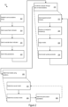
- FIG. 2 shows example coordination logic (CL) 200, which may be implemented on circuitry.
- the CL 200 establishes multiple communication links with multiple worker nodes (202).
- the communication links may be established via communications interface 312, discussed below.
- the multiple worker nodes each store a corresponding dataset partition of a global dataset.
- the entities controlling the multiple worker node may not necessarily allow disclosure, transfer, and/or other logically external or physically remote access of their respective dataset partitions. Accordingly, analysis of the dataset partition may be performed by physically localized and/or logically internal (e.g., within an organization and/or defined access group) computing resources.
- the CL 200 sends a causal indicator for a causal factor to each of the multiple worker nodes (204).
- the causal indicator does facilitate/cause identification of causal-factor-expressed data entries by the multiple worker nodes.
- the causal indicator does expressly identify a particular dataset (or set of data entries) for which the CL 200 may use to predict an outcome.
- the CL 200 may designate a set of potential result entries for which the CL 200 may determine to contribute to an observed outcome.
- the outcome may have an observable characteristic for which the causal factors are a potential cause.
- the CL 200 sends a covariate indicator to each of the multiple worker nodes (206).
- the covariate indicator identifies covariate-factor-expressed data entries for the causal indicators.
- the covariate entries form the inputs to the model of the causal-factor-expressed entries.
- the causal-factor-expressed entries may be expressed as a function (or other mathematical transformation) of the covariate-factor-expressed data entries to aid in the reduction/management of bias in the causal factor dataset.
- the CL 200 may send initial parameters to the multiple worker nodes (208).
- the initial parameters may define starting conditions such as an initial seed model, initial model states, and/or initial model parameters.
- the initial parameters may define rules for data handling, code for execution, or other initial state setup.
- the CL 200 coordinates analysis of the global dataset (e.g., the union of the partition dataset) through one or more iterations (250).
- the iterations each analyze the model and track convergence using a batch (e.g., a defined portion) of the global dataset.
- the CL 200 sends a respective batch indicator to a respective group of the multiple worker nodes (252).
- the respective batch indicator may indicate the global dataset entries that may be included with the batch for the current iteration. In some cases, other entries within the global dataset may be ignored or otherwise left unused for the current iteration.
- the CL 200 may generate and/or assign identifiers for each data entry within the global dataset. The identifiers may allow the CL 200 to track which data entries have been included in the analysis. To implement the global identifier assignment, the CL 200 may request an indication of the size of the data set partitions from the multiple worker nodes. Accordingly, the CL 200 may assign global identifiers without necessarily being given details about data entry content.
- the CL 200 may request that the multiple worker nodes track inclusion of data entries from their respective dataset partitions.
- the CL 200 may request inclusion of a specified number of entries.
- the CL 200 may allow repetitive inclusion of entries (e.g., repeated inclusion of entries before the entire global dataset is processed).
- the CL 200 may disallow such repetition.
- the CL 200 may progress deterministically (e.g., in accord with a mathematical function or predetermined scheme).
- the CL 200 may proceed non-deterministically (e.g., pseudo-randomly, randomly, stochastically, or otherwise without predictability) through the dataset (e.g., with or without repetition of entries).
- the CL 200 may not necessarily include every one of the multiple worker nodes in every iteration.
- one worker node may have no entries included in the batch for the current iteration.
- the worker nodes may have different numbers of entries from their respective dataset partitions included in the batch. In some cases, such differences may be correlated with differences in respective sizes of the dataset partitions. For example, larger dataset partitions may be more likely to be included in batches and more likely to have a larger number of entries selected for a batch. Conversely, smaller dataset partitions may be more likely to be excluded from a given batch and likely to have smaller number of entries selected.
- the batch entries may be selected in terms of the global dataset and independently of the respective worker nodes on which the entries are housed.
- a particular dataset may be overrepresented in an analysis relative to its size compared to other dataset partitions.
- the CL 200 may take contextual factors into account when selecting iteration batches.
- the worker nodes may analyze their respective dataset entries for the batch and the current model parameters. The worker nodes may then send model convergence indicators to the CL 200.
- the CL 200 may receive the corresponding respective model convergence indicators from each worker node of the group with entries included in the batch (254).
- worker nodes with no entries in the batch may forgo sending a convergence indicator for the iteration.
- worker nodes with no entries in the batch may send a dummy convergence indicator or no data indicator in place of a convergence indicator.
- the CL 200 may adjust the model based on the level of progress to convergence (256).
- the CL 200 may implement a gradient descent scheme (e.g., a mini-batch gradient decent scheme for batch-based) analysis.
- various parallelized machine learning computational models, regressions or other machine-based computations may be executed on the multiple worker node platform.
- the models may be fit to show a functional relationship, probabilistic relationship, or other mathematical relationship among observed or expressed characteristics of the data entries.
- the CL 200 may send a model parameter update in view of the adjustment to the model (258).
- Table 1 shows parameters for a gradient descent scheme.
- Table 1: Gradient Descent Scheme Worker nodes determine gradient descent ⁇ i for a number m i of dataset entries (x,y) and model function h ⁇ .
- Aggregate partial gradient values ⁇ (e.g. by summing over gradient values (or other convergence indicator) from N worker nodes.
- the CL 200 may determine various models using the iterations (260).
- the CL 200 may use the multiple iterations to determine a causal model (e.g., the outcome in terms of the causal-factor-expressed entries) (262), and one or more covariate model (264) (e.g., modeling the causal-factor-expressed entries in terms of the covariate-factor-expressed entries).
- a causal model e.g., the outcome in terms of the causal-factor-expressed entries
- covariate model e.g., modeling the causal-factor-expressed entries in terms of the covariate-factor-expressed entries.
- the CL 200 may determine perturbative parameters for the causal model (266), where the perturbative parameters are based on an estimate of the causal model expressed in terms of the covariate model(s).
- the perturbation to the causal model may allow for an assessment of dataset bias.
- the causal model may be adjusted to account for the bias.
- generation of an estimate of the causal model using the covariate model(s) may be used to implement a targeted maximum likelihood scheme.
- Table 2 shows parameters for a targeted maximum likelihood scheme.
- Table 2 Targeted Maximum Likelihood Scheme Parameters (This example covers binary treatment. However, non-binary (e.g.
- the targeted maximum likelihood scheme may be implemented by inverting the covariate model to determine covariate coefficients.
- the covariate coefficients may include the "clever" covariates shown in Table 2.
- the covariate model may be include a fit of a logarithmic function, a logit function, and/or a logistic function. Accordingly, inversion of the model may be standardized where a known or consistent model is used.
- the CL 200 may continue to run iterations to refine the causal and/or covariate models.
- the process may cycle until a convergence metric is met.
- various models may include defined accuracy metrics that can be assed using convergence indicators.
- the process may terminate after a defined number of convergence/perturbation iterations.
- an initial model may be determine and then perturbed and no further cycles may be implemented.
- initial "seed" models may be determined without iterative convergence. These initial models may be perturbed and then used to obtain convergence.
- causal models may be developed using different analysis tracks. For example, covariate models developing using iterative convergence may be used to perturb a seed causal model that is later refined through iterative convergence.
- various data structures may be used for the indicators and parameter used by the CL 200 and worker nodes.
- the causal indicator, covariate indicator, model convergence indicators, model update parameters and batch indicators include a raw data files, comma separated value files, javascript object notation files, yet another markup language files, extensible markup language files, or other data structure or message designed to convey parameters to support calculation.
- different ones of the different batch indicators, model update parameters, and/or model convergence indicators use different data structure/message types depending the corresponding worker node to which they are sent or received.
- different ones of the corresponding worker nodes may support (or not support) different data structure/message types.
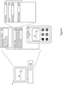
- FIG. 3 shows an example coordination execution environment (CEE) 300, which may provide an execution environment for implementing coordination of the multiple worker nodes.
- the CEE 300 may be used by, for example, a coordination node coordinating calculations by the multiple worker nodes.
- the CEE 300 may include system logic 314 to support tasks described in the drawings and/or claims.
- the system logic 314 may include processors 316, memory 320, and/or other circuitry, which may be used to implement CL 200, which may operate to coordinate the multiple worker nodes.
- the memory 320 may be used to store parameters 322 and/or model templates 324 used in the coordinated calculations.
- the memory 320 may further store selection rules 321, that may facilitate designation of covariates, data entries or other selections.
- the memory 320 may further include applications and structures, for example, coded objects, templates, or one or more other data structures to support coordinated calculations.
- the CEE 300 may also include one or more communication interfaces 312, which may support wireless, e.g. Bluetooth, Wi-Fi, WLAN, cellular (3G, 4G, LTE/A), and/or wired, ethernet, Gigabit ethernet, optical networking protocols.
- the communication interface 312 may support communication, e.g., through the communication layer as network interface circuitry, with worker nodes or other parties to facilitate coordinated calculations. Additionally or alternatively, the communication interface 312 may support secure information exchanges, such as secure socket layer (SSL) or public-key encryption-based protocols for sending and receiving private data.
- the CEE 300 may include power management circuitry 334 and one or more input interfaces 328.
- the CEE 300 may also include a user interface 318 that may include man-machine interfaces and/or graphical user interfaces (GUI).
- GUI graphical user interfaces
- the GUI may be used to present interfaces and or coordinated calculation options to operators working on behalf of the parties.
- FIG. 4 shows an example worker execution environment (WEE) 400, which may provide an execution environment for implementing of computation on a worker node.
- the WEE 400 may be used by, for example, a worker node being coordinated by coordination logic 200.
- the WEE 400 may include system logic 414 to support tasks including model calculations, such as gradient descent schemes.
- the system logic 414 may include processors 416, memory 420, and/or other circuitry, which may be used to implement worker node calculations and follow parameter updates from the CL 200.
- the memory 420 may be used to store parameters 422 and/or model templates 424 used in the worker node calculations.
- the memory 420 may further include applications and structures, for example, coded objects, templates, or one or more other data structures to support worker node calculations.
- the WEE 400 may also include one or more communication interfaces 412, which may support wireless, e.g. Bluetooth, Wi-Fi, WLAN, cellular (3G, 4G, LTE/A), and/or wired, ethernet, Gigabit ethernet, optical networking protocols.
- the communication interface 412 may support communication, e.g., through the communication layer as network interface circuitry, with the CL 200. Additionally or alternatively, the communication interface 412 may support secure information exchanges, such as secure socket layer (SSL) or public-key encryption-based protocols for sending and receiving private data.
- the WEE 400 may include power management circuitry 434 and one or more input interfaces 428.
- the WEE 400 may also include a user interface 418 that may include man-machine interfaces and/or graphical user interfaces (GUI).
- GUI graphical user interfaces
- the GUI may be used to present interfaces and or calculation participation options to operators working on behalf of the parties.
- circuitry that includes an instruction processor, such as a Central Processing Unit (CPU), microcontroller, or a microprocessor; an Application Specific Integrated Circuit (ASIC), Programmable Logic Device (PLD), or Field Programmable Gate Array (FPGA); or circuitry that includes discrete logic or other circuit components, including analog circuit components, digital circuit components or both; or any combination thereof.
- the circuitry may include discrete interconnected hardware components and/or may be combined on a single integrated circuit die, distributed among multiple integrated circuit dies, or implemented in a Multiple Chip Module (MCM) of multiple integrated circuit dies in a common package, as examples.
- MCM Multiple Chip Module
- the circuitry may further include or access instructions for execution by the circuitry.
- the instructions may be embodied as a signal and/or data stream and/or may be stored in a tangible storage medium that is other than a transitory signal, such as a flash memory, a Random Access Memory (RAM), a Read Only Memory (ROM), an Erasable Programmable Read Only Memory (EPROM); or on a magnetic or optical disc, such as a Compact Disc Read Only Memory (CDROM), Hard Disk Drive (HDD), or other magnetic or optical disk; or in or on another machine-readable medium.
- a product, such as a computer program product may particularly include a storage medium and instructions stored in or on the medium, and the instructions when executed by the circuitry in a device may cause the device to implement any of the processing described above or illustrated in the drawings.
- the implementations may be distributed as circuitry, e.g., hardware, and/or a combination of hardware and software among multiple system components, such as among multiple processors and memories, optionally including multiple distributed processing systems.
- Parameters, databases, and other data structures may be separately stored and managed, may be incorporated into a single memory or database, may be logically and physically organized in many different ways, and may be implemented in many different ways, including as data structures such as linked lists, hash tables, arrays, records, objects, or implicit storage mechanisms.
- Programs may be parts (e.g., subroutines) of a single program, separate programs, distributed across several memories and processors, or implemented in many different ways, such as in a library, such as a shared library (e.g., a Dynamic Link Library (DLL)).
- the DLL may store instructions that perform any of the processing described above or illustrated in the drawings, when executed by the circuitry.
Landscapes
- Engineering & Computer Science (AREA)
- Theoretical Computer Science (AREA)
- Software Systems (AREA)
- Physics & Mathematics (AREA)
- General Engineering & Computer Science (AREA)
- General Physics & Mathematics (AREA)
- Data Mining & Analysis (AREA)
- Artificial Intelligence (AREA)
- Evolutionary Computation (AREA)
- Computing Systems (AREA)
- Mathematical Physics (AREA)
- Computational Linguistics (AREA)
- Computer Vision & Pattern Recognition (AREA)
- Medical Informatics (AREA)
- Stored Programmes (AREA)
- Debugging And Monitoring (AREA)
- Information Retrieval, Db Structures And Fs Structures Therefor (AREA)
Description
- This disclosure relates to coordinating multiple worker nodes for distributed calculation.
- Rapid advances in electronics and communication technologies, driven by immense customer demand, have resulted in the widespread adoption of distributed computing. As one example, cloud computing operations involve up to exabytes or more of data analysis every year. Improvements in distributed computing execution will continue to increase the features and options available to operators of distributed computing operations.
- In International Patent Application Publication
WO2019/042571 there is described a system for distributed training of a machine learning model over a plurality of computing nodes, comprising a server connected to a plurality of computing nodes and configured to control a training of a machine learning model in a plurality of training iterations. Each of the training iterations comprising: instructing each of the computing nodes to train a respective local copy of the machine learning model by locally computing a respective one of a plurality of cumulative gradients each including one or more gradients, obtaining the cumulative gradients from each of the computing nodes and creating an updated machine learning model by merging the machine learning model with an aggregated value of the cumulative gradients. Wherein during the obtaining and creating phases, one or more of the computing nodes compute a new respective cumulative gradient that is merged with the machine learning model in a following training iteration. -
-
Figure 1 shows an example coordinated multiple-worker node environment. -
Figure 2 shows example coordination logic. -
Figure 3 shows an example coordination execution environment. -
Figure 4 shows an example worker execution environment. - Various aspects and embodiments of the present invention are set out in the appended claims.
- The various systems described below implement a gradient descent calculation, regression calculation, or other machine learning calculation on a dataset (e.g., a global dataset) using a coordination node including coordination circuitry that coordinates multiple worker nodes to create a distributed calculation architecture. The worker nodes each hold a portion of the dataset and operate on their respective portion.
- The gradient descent calculation, regression calculation, or other machine learning calculation is used, together with targeted maximum likelihood scheme for causal inference estimation. The targeted maximum likelihood scheme may be used to conduct causal analysis, manage bias or other sampling features of the dataset.
- Data available in one location (e.g., logical location and/or physical location) may not necessarily be available in another location (or any other location). For example, data may be private, sensitive, and/or proprietary. In some cases, data may be impossible, expensive or impractical to transfer (e.g., large datasets (potentially many terabyte in size or larger)). Nevertheless, the data may be analyzed to gain valuable insights. In some cases, those insights may be even more accurate if combined with data available at a second location. In various cases, there may be multiple "partition" datasets where for any given location at least one of the multiple dataset partitions is not available. As an illustrative example, each partition may include unique data such that for any given data entry it may only be accessible via its respective worker node. Non-availability may be more than an instance of non-local storage. Rather, non-availability may include true non-accessibility of the data from the location (whether the access attempt is local or remote). Accordingly, to perform a causal analysis on a global dataset that is a union of these dataset partitions a technical solution to the technical problem of applying computerized causal analysis on data where the authority applying the computerized causal analysis lacks access to various portions of the dataset being analyzed.
- In some cases, a coordination node may coordinate multiple worker nodes to perform localized computing on their respective dataset partitions. The coordination node may (in an iterative process) manage model convergence and/or dataset bias through a parameter provision and feedback system as discussed below. However, the coordination node may rely on the worker nodes to perform the portions of the analysis involving dataset interaction. The worker nodes may then feedback the analysis results rather than the underlying data itself. Accordingly, the underlying data need not necessarily be moved or remotely accessed by a singularly controlled computational entity. Rather, the data may remain unmoved while a global dataset analysis is performed.
-
Figure 1 shows an example coordinated multiple-worker node environment (CWE) 100. In the CWE 100, acoordination node 110 sends parameters 112 (e.g., initial parameters, updated parameters, or other parameters) to theworker nodes 120. Theworker nodes 120 perform the analysis and respond withconvergence indicators 122. - Referring now to
Figure 2 while continuing to refer toFigure 1 ,Figure 2 shows example coordination logic (CL) 200, which may be implemented on circuitry. TheCL 200 establishes multiple communication links with multiple worker nodes (202). For example, the communication links may be established viacommunications interface 312, discussed below. The multiple worker nodes each store a corresponding dataset partition of a global dataset. As discussed above, the entities controlling the multiple worker node may not necessarily allow disclosure, transfer, and/or other logically external or physically remote access of their respective dataset partitions. Accordingly, analysis of the dataset partition may be performed by physically localized and/or logically internal (e.g., within an organization and/or defined access group) computing resources. - The
CL 200 sends a causal indicator for a causal factor to each of the multiple worker nodes (204). The causal indicator does facilitate/cause identification of causal-factor-expressed data entries by the multiple worker nodes. For example, the causal indicator does expressly identify a particular dataset (or set of data entries) for which theCL 200 may use to predict an outcome. In other words, theCL 200 may designate a set of potential result entries for which theCL 200 may determine to contribute to an observed outcome. The outcome may have an observable characteristic for which the causal factors are a potential cause. - The
CL 200 sends a covariate indicator to each of the multiple worker nodes (206). The covariate indicator identifies covariate-factor-expressed data entries for the causal indicators. In other words, the covariate entries form the inputs to the model of the causal-factor-expressed entries. The causal-factor-expressed entries may be expressed as a function (or other mathematical transformation) of the covariate-factor-expressed data entries to aid in the reduction/management of bias in the causal factor dataset. - The
CL 200 may send initial parameters to the multiple worker nodes (208). The initial parameters may define starting conditions such as an initial seed model, initial model states, and/or initial model parameters. The initial parameters may define rules for data handling, code for execution, or other initial state setup. - The
CL 200 coordinates analysis of the global dataset (e.g., the union of the partition dataset) through one or more iterations (250). The iterations each analyze the model and track convergence using a batch (e.g., a defined portion) of the global dataset. - The
CL 200 sends a respective batch indicator to a respective group of the multiple worker nodes (252). The respective batch indicator may indicate the global dataset entries that may be included with the batch for the current iteration. In some cases, other entries within the global dataset may be ignored or otherwise left unused for the current iteration. In some cases, theCL 200 may generate and/or assign identifiers for each data entry within the global dataset. The identifiers may allow theCL 200 to track which data entries have been included in the analysis. To implement the global identifier assignment, theCL 200 may request an indication of the size of the data set partitions from the multiple worker nodes. Accordingly, theCL 200 may assign global identifiers without necessarily being given details about data entry content. In some cases, theCL 200 may request that the multiple worker nodes track inclusion of data entries from their respective dataset partitions. TheCL 200 may request inclusion of a specified number of entries. TheCL 200 may allow repetitive inclusion of entries (e.g., repeated inclusion of entries before the entire global dataset is processed). In some cases, theCL 200 may disallow such repetition. For example, theCL 200 may progress deterministically (e.g., in accord with a mathematical function or predetermined scheme). In some cases, theCL 200 may proceed non-deterministically (e.g., pseudo-randomly, randomly, stochastically, or otherwise without predictability) through the dataset (e.g., with or without repetition of entries). - In some cases, the
CL 200 may not necessarily include every one of the multiple worker nodes in every iteration. In some cases, one worker node may have no entries included in the batch for the current iteration. In some cases, the worker nodes may have different numbers of entries from their respective dataset partitions included in the batch. In some cases, such differences may be correlated with differences in respective sizes of the dataset partitions. For example, larger dataset partitions may be more likely to be included in batches and more likely to have a larger number of entries selected for a batch. Conversely, smaller dataset partitions may be more likely to be excluded from a given batch and likely to have smaller number of entries selected. In some cases, the batch entries may be selected in terms of the global dataset and independently of the respective worker nodes on which the entries are housed. - In some cases, when managing sample bias a particular dataset may be overrepresented in an analysis relative to its size compared to other dataset partitions. In some cases, the
CL 200 may take contextual factors into account when selecting iteration batches. - The worker nodes may analyze their respective dataset entries for the batch and the current model parameters. The worker nodes may then send model convergence indicators to the
CL 200. - The
CL 200 may receive the corresponding respective model convergence indicators from each worker node of the group with entries included in the batch (254). In some cases, worker nodes with no entries in the batch may forgo sending a convergence indicator for the iteration. In some cases, worker nodes with no entries in the batch may send a dummy convergence indicator or no data indicator in place of a convergence indicator. - After receiving the convergence indicators, the
CL 200 may adjust the model based on the level of progress to convergence (256). For example, theCL 200 may implement a gradient descent scheme (e.g., a mini-batch gradient decent scheme for batch-based) analysis. However, various parallelized machine learning computational models, regressions or other machine-based computations may be executed on the multiple worker node platform. Additionally or alternatively, the models may be fit to show a functional relationship, probabilistic relationship, or other mathematical relationship among observed or expressed characteristics of the data entries. - The
CL 200 may send a model parameter update in view of the adjustment to the model (258).Table 1 shows parameters for a gradient descent scheme. Table 1: Gradient Descent Scheme Worker nodes determine gradient descent Δi for a number mi of dataset entries (x,y) and model function hθ. 
Aggregate partial gradient values Δ (e.g. by summing over gradient values (or other convergence indicator) from N worker nodes. 
Update model parameters θ. 
Check for convergence (e.g. by determining that iterative adjustment to model parameter is smaller than a convergence metric ε, and is decreasing). |θ τ+1 - θτ | ≤ε Broadcast updated model parameters. θ τ+1 - The
CL 200 may determine various models using the iterations (260). - The
CL 200 may use the multiple iterations to determine a causal model (e.g., the outcome in terms of the causal-factor-expressed entries) (262), and one or more covariate model (264) (e.g., modeling the causal-factor-expressed entries in terms of the covariate-factor-expressed entries). - After obtaining initial causal and covariate models, the
CL 200 may determine perturbative parameters for the causal model (266), where the perturbative parameters are based on an estimate of the causal model expressed in terms of the covariate model(s). The perturbation to the causal model may allow for an assessment of dataset bias. The causal model may be adjusted to account for the bias. In some cases, generation of an estimate of the causal model using the covariate model(s) may be used to implement a targeted maximum likelihood scheme.Table 2 shows parameters for a targeted maximum likelihood scheme. Table 2: Targeted Maximum Likelihood Scheme Parameters (This example covers binary treatment. However, non-binary (e.g. discrete or continuous variable) treatments may be used.) Y - outcome A - Treatment (0: no treatment, 1: treatment) W - covariates Fit a machine learning model to estimate g(Y)~f(W,A) Y as a function of (W,A). Ŷ 0 = g -1(f(W,A = 0)) Ŷ 1 = g -1(f(W,A = 1)) Fit to a binary classification model to estimate A as function of covariates W. A~h(W) In some cases, a logistic regression may be used for the model function h. A~logit(θW) → θ̂ Predict the propensity score, where expit() is the inverse of the logit() function. π̂ 1 = expit(θ̂W) π̂ 0 = 1 - π̂ 1 Estimate "clever" covariates Ĥ 0 and Ĥ 1. 

- The targeted maximum likelihood scheme may be implemented by inverting the covariate model to determine covariate coefficients. In some cases, the covariate coefficients may include the "clever" covariates shown in Table 2. In some cases, the covariate model may be include a fit of a logarithmic function, a logit function, and/or a logistic function. Accordingly, inversion of the model may be standardized where a known or consistent model is used.
- After the perturbative parameters are obtained, the
CL 200 may continue to run iterations to refine the causal and/or covariate models. In some cases, the process may cycle until a convergence metric is met. For example, various models may include defined accuracy metrics that can be assed using convergence indicators. In some cases, the process may terminate after a defined number of convergence/perturbation iterations. Additionally or alternatively, an initial model may be determine and then perturbed and no further cycles may be implemented. In some cases, initial "seed" models may be determined without iterative convergence. These initial models may be perturbed and then used to obtain convergence. In various cases, causal models may be developed using different analysis tracks. For example, covariate models developing using iterative convergence may be used to perturb a seed causal model that is later refined through iterative convergence. - In various implementations, various data structures may be used for the indicators and parameter used by the
CL 200 and worker nodes. For example, the causal indicator, covariate indicator, model convergence indicators, model update parameters and batch indicators include a raw data files, comma separated value files, javascript object notation files, yet another markup language files, extensible markup language files, or other data structure or message designed to convey parameters to support calculation. In some cases different ones of the different batch indicators, model update parameters, and/or model convergence indicators use different data structure/message types depending the corresponding worker node to which they are sent or received. For example, different ones of the corresponding worker nodes may support (or not support) different data structure/message types. -
Figure 3 shows an example coordination execution environment (CEE) 300, which may provide an execution environment for implementing coordination of the multiple worker nodes. TheCEE 300 may be used by, for example, a coordination node coordinating calculations by the multiple worker nodes. TheCEE 300 may includesystem logic 314 to support tasks described in the drawings and/or claims. Thesystem logic 314 may includeprocessors 316,memory 320, and/or other circuitry, which may be used to implementCL 200, which may operate to coordinate the multiple worker nodes. - The
memory 320 may be used to storeparameters 322 and/ormodel templates 324 used in the coordinated calculations. Thememory 320 may further storeselection rules 321, that may facilitate designation of covariates, data entries or other selections. - The
memory 320 may further include applications and structures, for example, coded objects, templates, or one or more other data structures to support coordinated calculations. TheCEE 300 may also include one ormore communication interfaces 312, which may support wireless, e.g. Bluetooth, Wi-Fi, WLAN, cellular (3G, 4G, LTE/A), and/or wired, ethernet, Gigabit ethernet, optical networking protocols. Thecommunication interface 312 may support communication, e.g., through the communication layer as network interface circuitry, with worker nodes or other parties to facilitate coordinated calculations. Additionally or alternatively, thecommunication interface 312 may support secure information exchanges, such as secure socket layer (SSL) or public-key encryption-based protocols for sending and receiving private data. TheCEE 300 may includepower management circuitry 334 and one or more input interfaces 328. - The
CEE 300 may also include a user interface 318 that may include man-machine interfaces and/or graphical user interfaces (GUI). The GUI may be used to present interfaces and or coordinated calculation options to operators working on behalf of the parties. -
Figure 4 shows an example worker execution environment (WEE) 400, which may provide an execution environment for implementing of computation on a worker node. TheWEE 400 may be used by, for example, a worker node being coordinated bycoordination logic 200. TheWEE 400 may includesystem logic 414 to support tasks including model calculations, such as gradient descent schemes. Thesystem logic 414 may includeprocessors 416,memory 420, and/or other circuitry, which may be used to implement worker node calculations and follow parameter updates from theCL 200. - The
memory 420 may be used to storeparameters 422 and/ormodel templates 424 used in the worker node calculations. - The
memory 420 may further include applications and structures, for example, coded objects, templates, or one or more other data structures to support worker node calculations. TheWEE 400 may also include one ormore communication interfaces 412, which may support wireless, e.g. Bluetooth, Wi-Fi, WLAN, cellular (3G, 4G, LTE/A), and/or wired, ethernet, Gigabit ethernet, optical networking protocols. Thecommunication interface 412 may support communication, e.g., through the communication layer as network interface circuitry, with theCL 200. Additionally or alternatively, thecommunication interface 412 may support secure information exchanges, such as secure socket layer (SSL) or public-key encryption-based protocols for sending and receiving private data. TheWEE 400 may includepower management circuitry 434 and one or more input interfaces 428. - The
WEE 400 may also include a user interface 418 that may include man-machine interfaces and/or graphical user interfaces (GUI). The GUI may be used to present interfaces and or calculation participation options to operators working on behalf of the parties. - The methods, devices, processing, and logic described above may be implemented in many different ways and in many different combinations of hardware and software. For example, all or parts of the implementations may be circuitry that includes an instruction processor, such as a Central Processing Unit (CPU), microcontroller, or a microprocessor; an Application Specific Integrated Circuit (ASIC), Programmable Logic Device (PLD), or Field Programmable Gate Array (FPGA); or circuitry that includes discrete logic or other circuit components, including analog circuit components, digital circuit components or both; or any combination thereof. The circuitry may include discrete interconnected hardware components and/or may be combined on a single integrated circuit die, distributed among multiple integrated circuit dies, or implemented in a Multiple Chip Module (MCM) of multiple integrated circuit dies in a common package, as examples.
- The circuitry may further include or access instructions for execution by the circuitry. The instructions may be embodied as a signal and/or data stream and/or may be stored in a tangible storage medium that is other than a transitory signal, such as a flash memory, a Random Access Memory (RAM), a Read Only Memory (ROM), an Erasable Programmable Read Only Memory (EPROM); or on a magnetic or optical disc, such as a Compact Disc Read Only Memory (CDROM), Hard Disk Drive (HDD), or other magnetic or optical disk; or in or on another machine-readable medium. A product, such as a computer program product, may particularly include a storage medium and instructions stored in or on the medium, and the instructions when executed by the circuitry in a device may cause the device to implement any of the processing described above or illustrated in the drawings.
- The implementations may be distributed as circuitry, e.g., hardware, and/or a combination of hardware and software among multiple system components, such as among multiple processors and memories, optionally including multiple distributed processing systems. Parameters, databases, and other data structures may be separately stored and managed, may be incorporated into a single memory or database, may be logically and physically organized in many different ways, and may be implemented in many different ways, including as data structures such as linked lists, hash tables, arrays, records, objects, or implicit storage mechanisms. Programs may be parts (e.g., subroutines) of a single program, separate programs, distributed across several memories and processors, or implemented in many different ways, such as in a library, such as a shared library (e.g., a Dynamic Link Library (DLL)). The DLL, for example, may store instructions that perform any of the processing described above or illustrated in the drawings, when executed by the circuitry.
- Various implementations have been specifically described. However, many other implementations are also possible.
- Headings and/or subheadings used herein are intended only to aid the reader with understanding described implementations.
Claims (9)
- A computer-implemented method performed by a coordination node (110) to determine a causal model based on a global dataset via a plurality of model iterations, the causal model having model parameters (112), wherein each worker node in a plurality of worker nodes (120) stores a corresponding dataset partition of the global dataset that is not accessible to the coordination node (110), the method comprising:establishing (202) communication links with the plurality of worker nodes (120);sending (204) a causal indicator for a causal factor to each of the plurality of worker nodes (120), the causal indicator for causing identification of causal-factor-expressed data entries of the respective datasets by the plurality of worker nodes;sending (206) a covariate indicator to each of the plurality of worker nodes (120), the covariate indicator for identifying covariate-factor-expressed data entries forming the inputs for the causal-factor-expressed data entries;sending (208) initial model parameters to the plurality of worker nodes; andfor each model iteration of the plurality of model iterations (250):selecting a respective batch from the global dataset;generating and sending (252) a respective batch indicator to a respective group of the plurality of worker nodes, said respective batch indicator indicating global dataset entries that are included within the respective batch for the model iteration, wherein the corresponding dataset partitions of each worker node of the respective group include a portion of the respective batch selected from the global dataset;receiving (254) a corresponding respective model convergence indicator from each worker node of the respective group, the model convergence indicator resulting from the analysis by the worker nodes of their respective dataset entries for the current model parameters;adjusting the model and generating updated model parameters (256) based on one or more respective model convergence indicators received from the respective group; andsending (258), to each of the plurality of worker nodes, the updated model parameters;wherein the model iterations implement a mini-batch gradient descent scheme based on the received model convergence indicators;wherein the method further includes determining the model using the mini-batch gradient descent scheme, by modelling the causal-factor-expressed data entries in terms of the covariate-factor-expressed data entries; andwherein the respective batch indicator designates specific data entries of the global dataset for inclusion in a respective mini-batch selected independently of which dataset partitions include the specific data entries.
- The method of claim 1, where a first corresponding dataset partition of a first of the plurality of worker nodes contains first data not present in any of the other corresponding dataset partitions.
- The method of any one of the preceding claims, where causal factor includes an observable characteristic with a potential causal relationship for an outcome; and
the outcome includes an observable characteristic present for the causal-factor-expressed data entries present in the global dataset. - The method of any one of the preceding claims, where the plurality of model iterations implement a machine learning computation, regression algorithm, or both.
- The method of claim 1, where designation of the specific data entries is performed non-deterministically.
- The method of claim 5, where designation of the specific data entries progresses through the global dataset without repetition of entries.
- The method of any one of the preceding claims, where the coordination node is configured to implement a targeted maximum likelihood scheme by determining an estimate of the causal model as a function of a covariate model.
- The method of claim 7, where the coordination node is configured to obtain perturbative parameters based on the causal model and the covariate model by:causing inversion of the covariate model to determine covariate coefficients; andcausing perturbation of the causal model with factors based on the covariate coefficients to determine the perturbative parameters.
- A system including network interface circuitry configured to establish a plurality of communication links with a plurality of worker nodes, the plurality of worker nodes each being configured to store a corresponding dataset partition of a global dataset, the system arranged to carry out the method of any one of claims 1-8.
Applications Claiming Priority (1)
| Application Number | Priority Date | Filing Date | Title |
|---|---|---|---|
| US201962865022P | 2019-06-21 | 2019-06-21 |
Publications (2)
| Publication Number | Publication Date |
|---|---|
| EP3754502A1 EP3754502A1 (en) | 2020-12-23 |
| EP3754502B1 true EP3754502B1 (en) | 2024-11-06 |
Family
ID=71111302
Family Applications (1)
| Application Number | Title | Priority Date | Filing Date |
|---|---|---|---|
| EP20181047.0A Active EP3754502B1 (en) | 2019-06-21 | 2020-06-19 | Coordinated multiple worker node causal inference framework |
Country Status (2)
| Country | Link |
|---|---|
| US (1) | US11574216B2 (en) |
| EP (1) | EP3754502B1 (en) |
Families Citing this family (3)
| Publication number | Priority date | Publication date | Assignee | Title |
|---|---|---|---|---|
| TWI764694B (en) * | 2020-10-12 | 2022-05-11 | 威聯通科技股份有限公司 | Containerized application management system and management method |
| US12511554B2 (en) * | 2021-06-17 | 2025-12-30 | Accenture Global Solutions Limited | Complex system for end-to-end causal inference |
| CN118569379B (en) * | 2024-07-31 | 2024-10-25 | 中国人民解放军国防科技大学 | Continuous optimization-based causal discovery method, device, equipment and medium |
Family Cites Families (8)
| Publication number | Priority date | Publication date | Assignee | Title |
|---|---|---|---|---|
| CN103745225A (en) | 2013-12-27 | 2014-04-23 | 北京集奥聚合网络技术有限公司 | Method and system for training distributed CTR (Click To Rate) prediction model |
| US9503466B2 (en) * | 2014-01-06 | 2016-11-22 | Cisco Technology, Inc. | Cross-validation of a learning machine model across network devices |
| US9614651B1 (en) * | 2014-01-23 | 2017-04-04 | Sprint Spectrum L.P. | Coordinating wireless communication with access nodes |
| US10129158B2 (en) * | 2015-04-17 | 2018-11-13 | Parallel Wireless, Inc. | MaxMesh: mesh backhaul routing |
| US10983957B2 (en) * | 2015-07-27 | 2021-04-20 | Sas Institute Inc. | Distributed columnar data set storage |
| US11087234B2 (en) * | 2016-01-29 | 2021-08-10 | Verizon Media Inc. | Method and system for distributed deep machine learning |
| US10296849B2 (en) * | 2017-02-15 | 2019-05-21 | Microsoft Technology Licensing, Llc | Member clustering with equi-sized partitions |
| WO2019042571A1 (en) | 2017-09-04 | 2019-03-07 | Huawei Technologies Co., Ltd. | Asynchronous gradient averaging distributed stochastic gradient descent |
-
2020
- 2020-06-19 US US16/906,759 patent/US11574216B2/en active Active
- 2020-06-19 EP EP20181047.0A patent/EP3754502B1/en active Active
Also Published As
| Publication number | Publication date |
|---|---|
| US11574216B2 (en) | 2023-02-07 |
| US20200401915A1 (en) | 2020-12-24 |
| EP3754502A1 (en) | 2020-12-23 |
Similar Documents
| Publication | Publication Date | Title |
|---|---|---|
| US12299552B2 (en) | Training tree-based machine-learning modeling algorithms for predicting outputs and generating explanatory data | |
| US10360517B2 (en) | Distributed hyperparameter tuning system for machine learning | |
| US10963802B1 (en) | Distributed decision variable tuning system for machine learning | |
| US10095981B1 (en) | Multi-state quantum optimization engine | |
| EP4006788B1 (en) | Quantum circuit determining method and apparatus, device, and storage medium | |
| EP3392808A1 (en) | Solving computational tasks using quantum computing | |
| US9576031B1 (en) | Automated outlier detection | |
| US10067746B1 (en) | Approximate random number generator by empirical cumulative distribution function | |
| US20130346033A1 (en) | Tree-based regression | |
| CN111898867B (en) | Airplane final assembly production line productivity prediction method based on deep neural network | |
| US11574216B2 (en) | Coordinated multiple worker node causal inference framework | |
| US10901993B2 (en) | Performing cache update adaptation | |
| CN117634101B (en) | Chip surface morphology determination method, chip surface morphology determination device, computer device and storage medium | |
| US20220391555A1 (en) | Method and tool for designing a complex system | |
| CN119668529B (en) | Distributed storage electronic data processing system | |
| US20230004870A1 (en) | Machine learning model determination system and machine learning model determination method | |
| CN111122222A (en) | A method and system for determining the location of a sample point | |
| EP4198831A1 (en) | Automated feature engineering for predictive modeling using deep reinforcement learning | |
| US10496948B1 (en) | Computer trend visualization using quadratic simplified closed form linear regression | |
| Rilling et al. | A new p-value based multiple testing procedure for generalized linear models | |
| US7890439B2 (en) | Tuning of problem solvers | |
| Ruiz-Ortiz et al. | A new definition of hitting time and an embedded Markov chain in continuous-time quantum walks: MA Ruiz-Ortiz et al. | |
| CN117640656A (en) | Communication-efficient and centerless distributed optimization training methods, devices and equipment | |
| Morey et al. | A Hybrid Approach Combining Simulation and a Queueing Model for Optimizing a Biomanufacturing System | |
| Ngufor et al. | Learning from large distributed data: A scaling down sampling scheme for efficient data processing |
Legal Events
| Date | Code | Title | Description |
|---|---|---|---|
| PUAI | Public reference made under article 153(3) epc to a published international application that has entered the european phase |
Free format text: ORIGINAL CODE: 0009012 |
|
| STAA | Information on the status of an ep patent application or granted ep patent |
Free format text: STATUS: THE APPLICATION HAS BEEN PUBLISHED |
|
| AK | Designated contracting states |
Kind code of ref document: A1 Designated state(s): AL AT BE BG CH CY CZ DE DK EE ES FI FR GB GR HR HU IE IS IT LI LT LU LV MC MK MT NL NO PL PT RO RS SE SI SK SM TR |
|
| AX | Request for extension of the european patent |
Extension state: BA ME |
|
| STAA | Information on the status of an ep patent application or granted ep patent |
Free format text: STATUS: REQUEST FOR EXAMINATION WAS MADE |
|
| 17P | Request for examination filed |
Effective date: 20210521 |
|
| RBV | Designated contracting states (corrected) |
Designated state(s): AL AT BE BG CH CY CZ DE DK EE ES FI FR GB GR HR HU IE IS IT LI LT LU LV MC MK MT NL NO PL PT RO RS SE SI SK SM TR |
|
| STAA | Information on the status of an ep patent application or granted ep patent |
Free format text: STATUS: EXAMINATION IS IN PROGRESS |
|
| 17Q | First examination report despatched |
Effective date: 20220217 |
|
| GRAP | Despatch of communication of intention to grant a patent |
Free format text: ORIGINAL CODE: EPIDOSNIGR1 |
|
| STAA | Information on the status of an ep patent application or granted ep patent |
Free format text: STATUS: GRANT OF PATENT IS INTENDED |
|
| INTG | Intention to grant announced |
Effective date: 20240605 |
|
| GRAS | Grant fee paid |
Free format text: ORIGINAL CODE: EPIDOSNIGR3 |
|
| GRAA | (expected) grant |
Free format text: ORIGINAL CODE: 0009210 |
|
| STAA | Information on the status of an ep patent application or granted ep patent |
Free format text: STATUS: THE PATENT HAS BEEN GRANTED |
|
| AK | Designated contracting states |
Kind code of ref document: B1 Designated state(s): AL AT BE BG CH CY CZ DE DK EE ES FI FR GB GR HR HU IE IS IT LI LT LU LV MC MK MT NL NO PL PT RO RS SE SI SK SM TR |
|
| REG | Reference to a national code |
Ref country code: GB Ref legal event code: FG4D |
|
| P01 | Opt-out of the competence of the unified patent court (upc) registered |
Free format text: CASE NUMBER: APP_55254/2024 Effective date: 20241008 |
|
| REG | Reference to a national code |
Ref country code: CH Ref legal event code: EP |
|
| REG | Reference to a national code |
Ref country code: DE Ref legal event code: R096 Ref document number: 602020040682 Country of ref document: DE |
|
| REG | Reference to a national code |
Ref country code: IE Ref legal event code: FG4D |
|
| REG | Reference to a national code |
Ref country code: LT Ref legal event code: MG9D |
|
| REG | Reference to a national code |
Ref country code: NL Ref legal event code: MP Effective date: 20241106 |
|
| PG25 | Lapsed in a contracting state [announced via postgrant information from national office to epo] |
Ref country code: PT Free format text: LAPSE BECAUSE OF FAILURE TO SUBMIT A TRANSLATION OF THE DESCRIPTION OR TO PAY THE FEE WITHIN THE PRESCRIBED TIME-LIMIT Effective date: 20250306 Ref country code: HR Free format text: LAPSE BECAUSE OF FAILURE TO SUBMIT A TRANSLATION OF THE DESCRIPTION OR TO PAY THE FEE WITHIN THE PRESCRIBED TIME-LIMIT Effective date: 20241106 Ref country code: IS Free format text: LAPSE BECAUSE OF FAILURE TO SUBMIT A TRANSLATION OF THE DESCRIPTION OR TO PAY THE FEE WITHIN THE PRESCRIBED TIME-LIMIT Effective date: 20250306 |
|
| PG25 | Lapsed in a contracting state [announced via postgrant information from national office to epo] |
Ref country code: NL Free format text: LAPSE BECAUSE OF FAILURE TO SUBMIT A TRANSLATION OF THE DESCRIPTION OR TO PAY THE FEE WITHIN THE PRESCRIBED TIME-LIMIT Effective date: 20241106 Ref country code: FI Free format text: LAPSE BECAUSE OF FAILURE TO SUBMIT A TRANSLATION OF THE DESCRIPTION OR TO PAY THE FEE WITHIN THE PRESCRIBED TIME-LIMIT Effective date: 20241106 |
|
| REG | Reference to a national code |
Ref country code: AT Ref legal event code: MK05 Ref document number: 1740121 Country of ref document: AT Kind code of ref document: T Effective date: 20241106 |
|
| PG25 | Lapsed in a contracting state [announced via postgrant information from national office to epo] |
Ref country code: BG Free format text: LAPSE BECAUSE OF FAILURE TO SUBMIT A TRANSLATION OF THE DESCRIPTION OR TO PAY THE FEE WITHIN THE PRESCRIBED TIME-LIMIT Effective date: 20241106 |
|
| PG25 | Lapsed in a contracting state [announced via postgrant information from national office to epo] |
Ref country code: ES Free format text: LAPSE BECAUSE OF FAILURE TO SUBMIT A TRANSLATION OF THE DESCRIPTION OR TO PAY THE FEE WITHIN THE PRESCRIBED TIME-LIMIT Effective date: 20241106 |
|
| PG25 | Lapsed in a contracting state [announced via postgrant information from national office to epo] |
Ref country code: NO Free format text: LAPSE BECAUSE OF FAILURE TO SUBMIT A TRANSLATION OF THE DESCRIPTION OR TO PAY THE FEE WITHIN THE PRESCRIBED TIME-LIMIT Effective date: 20250206 |
|
| PG25 | Lapsed in a contracting state [announced via postgrant information from national office to epo] |
Ref country code: GR Free format text: LAPSE BECAUSE OF FAILURE TO SUBMIT A TRANSLATION OF THE DESCRIPTION OR TO PAY THE FEE WITHIN THE PRESCRIBED TIME-LIMIT Effective date: 20250207 Ref country code: LV Free format text: LAPSE BECAUSE OF FAILURE TO SUBMIT A TRANSLATION OF THE DESCRIPTION OR TO PAY THE FEE WITHIN THE PRESCRIBED TIME-LIMIT Effective date: 20241106 Ref country code: AT Free format text: LAPSE BECAUSE OF FAILURE TO SUBMIT A TRANSLATION OF THE DESCRIPTION OR TO PAY THE FEE WITHIN THE PRESCRIBED TIME-LIMIT Effective date: 20241106 |
|
| PG25 | Lapsed in a contracting state [announced via postgrant information from national office to epo] |
Ref country code: PL Free format text: LAPSE BECAUSE OF FAILURE TO SUBMIT A TRANSLATION OF THE DESCRIPTION OR TO PAY THE FEE WITHIN THE PRESCRIBED TIME-LIMIT Effective date: 20241106 |
|
| PG25 | Lapsed in a contracting state [announced via postgrant information from national office to epo] |
Ref country code: RS Free format text: LAPSE BECAUSE OF FAILURE TO SUBMIT A TRANSLATION OF THE DESCRIPTION OR TO PAY THE FEE WITHIN THE PRESCRIBED TIME-LIMIT Effective date: 20250206 |
|
| PG25 | Lapsed in a contracting state [announced via postgrant information from national office to epo] |
Ref country code: SM Free format text: LAPSE BECAUSE OF FAILURE TO SUBMIT A TRANSLATION OF THE DESCRIPTION OR TO PAY THE FEE WITHIN THE PRESCRIBED TIME-LIMIT Effective date: 20241106 |
|
| PGFP | Annual fee paid to national office [announced via postgrant information from national office to epo] |
Ref country code: DE Payment date: 20250402 Year of fee payment: 6 |
|
| PG25 | Lapsed in a contracting state [announced via postgrant information from national office to epo] |
Ref country code: DK Free format text: LAPSE BECAUSE OF FAILURE TO SUBMIT A TRANSLATION OF THE DESCRIPTION OR TO PAY THE FEE WITHIN THE PRESCRIBED TIME-LIMIT Effective date: 20241106 |
|
| PGFP | Annual fee paid to national office [announced via postgrant information from national office to epo] |
Ref country code: GB Payment date: 20250401 Year of fee payment: 6 |
|
| PG25 | Lapsed in a contracting state [announced via postgrant information from national office to epo] |
Ref country code: EE Free format text: LAPSE BECAUSE OF FAILURE TO SUBMIT A TRANSLATION OF THE DESCRIPTION OR TO PAY THE FEE WITHIN THE PRESCRIBED TIME-LIMIT Effective date: 20241106 |
|
| PGFP | Annual fee paid to national office [announced via postgrant information from national office to epo] |
Ref country code: FR Payment date: 20250409 Year of fee payment: 6 |
|
| PG25 | Lapsed in a contracting state [announced via postgrant information from national office to epo] |
Ref country code: RO Free format text: LAPSE BECAUSE OF FAILURE TO SUBMIT A TRANSLATION OF THE DESCRIPTION OR TO PAY THE FEE WITHIN THE PRESCRIBED TIME-LIMIT Effective date: 20241106 |
|
| PG25 | Lapsed in a contracting state [announced via postgrant information from national office to epo] |
Ref country code: SK Free format text: LAPSE BECAUSE OF FAILURE TO SUBMIT A TRANSLATION OF THE DESCRIPTION OR TO PAY THE FEE WITHIN THE PRESCRIBED TIME-LIMIT Effective date: 20241106 |
|
| PG25 | Lapsed in a contracting state [announced via postgrant information from national office to epo] |
Ref country code: CZ Free format text: LAPSE BECAUSE OF FAILURE TO SUBMIT A TRANSLATION OF THE DESCRIPTION OR TO PAY THE FEE WITHIN THE PRESCRIBED TIME-LIMIT Effective date: 20241106 |
|
| PG25 | Lapsed in a contracting state [announced via postgrant information from national office to epo] |
Ref country code: IT Free format text: LAPSE BECAUSE OF FAILURE TO SUBMIT A TRANSLATION OF THE DESCRIPTION OR TO PAY THE FEE WITHIN THE PRESCRIBED TIME-LIMIT Effective date: 20241106 |
|
| PGFP | Annual fee paid to national office [announced via postgrant information from national office to epo] |
Ref country code: IE Payment date: 20250402 Year of fee payment: 6 |
|
| REG | Reference to a national code |
Ref country code: DE Ref legal event code: R097 Ref document number: 602020040682 Country of ref document: DE |
|
| PG25 | Lapsed in a contracting state [announced via postgrant information from national office to epo] |
Ref country code: SE Free format text: LAPSE BECAUSE OF FAILURE TO SUBMIT A TRANSLATION OF THE DESCRIPTION OR TO PAY THE FEE WITHIN THE PRESCRIBED TIME-LIMIT Effective date: 20241106 |
|
| PLBE | No opposition filed within time limit |
Free format text: ORIGINAL CODE: 0009261 |
|
| STAA | Information on the status of an ep patent application or granted ep patent |
Free format text: STATUS: NO OPPOSITION FILED WITHIN TIME LIMIT |
|
| 26N | No opposition filed |
Effective date: 20250807 |
|
| REG | Reference to a national code |
Ref country code: CH Ref legal event code: H13 Free format text: ST27 STATUS EVENT CODE: U-0-0-H10-H13 (AS PROVIDED BY THE NATIONAL OFFICE) Effective date: 20260127 |
|
| PG25 | Lapsed in a contracting state [announced via postgrant information from national office to epo] |
Ref country code: MC Free format text: LAPSE BECAUSE OF FAILURE TO SUBMIT A TRANSLATION OF THE DESCRIPTION OR TO PAY THE FEE WITHIN THE PRESCRIBED TIME-LIMIT Effective date: 20241106 |
|
| PG25 | Lapsed in a contracting state [announced via postgrant information from national office to epo] |
Ref country code: LU Free format text: LAPSE BECAUSE OF NON-PAYMENT OF DUE FEES Effective date: 20250619 |
|
| REG | Reference to a national code |
Ref country code: BE Ref legal event code: MM Effective date: 20250630 |
|
| PG25 | Lapsed in a contracting state [announced via postgrant information from national office to epo] |
Ref country code: BE Free format text: LAPSE BECAUSE OF NON-PAYMENT OF DUE FEES Effective date: 20250630 |
|
| PG25 | Lapsed in a contracting state [announced via postgrant information from national office to epo] |
Ref country code: CH Free format text: LAPSE BECAUSE OF NON-PAYMENT OF DUE FEES Effective date: 20250630 |