EP3754474A1 - Touch controller, related chip, touch control system, and touch control method - Google Patents
Touch controller, related chip, touch control system, and touch control method Download PDFInfo
- Publication number
- EP3754474A1 EP3754474A1 EP19916536.6A EP19916536A EP3754474A1 EP 3754474 A1 EP3754474 A1 EP 3754474A1 EP 19916536 A EP19916536 A EP 19916536A EP 3754474 A1 EP3754474 A1 EP 3754474A1
- Authority
- EP
- European Patent Office
- Prior art keywords
- transmitting
- signal
- phase code
- electrode
- phase
- Prior art date
- Legal status (The legal status is an assumption and is not a legal conclusion. Google has not performed a legal analysis and makes no representation as to the accuracy of the status listed.)
- Pending
Links
Images


Classifications
-
- G—PHYSICS
- G06—COMPUTING OR CALCULATING; COUNTING
- G06F—ELECTRIC DIGITAL DATA PROCESSING
- G06F3/00—Input arrangements for transferring data to be processed into a form capable of being handled by the computer; Output arrangements for transferring data from processing unit to output unit, e.g. interface arrangements
- G06F3/01—Input arrangements or combined input and output arrangements for interaction between user and computer
- G06F3/03—Arrangements for converting the position or the displacement of a member into a coded form
- G06F3/041—Digitisers, e.g. for touch screens or touch pads, characterised by the transducing means
- G06F3/044—Digitisers, e.g. for touch screens or touch pads, characterised by the transducing means by capacitive means
-
- G—PHYSICS
- G06—COMPUTING OR CALCULATING; COUNTING
- G06F—ELECTRIC DIGITAL DATA PROCESSING
- G06F3/00—Input arrangements for transferring data to be processed into a form capable of being handled by the computer; Output arrangements for transferring data from processing unit to output unit, e.g. interface arrangements
- G06F3/01—Input arrangements or combined input and output arrangements for interaction between user and computer
- G06F3/03—Arrangements for converting the position or the displacement of a member into a coded form
- G06F3/041—Digitisers, e.g. for touch screens or touch pads, characterised by the transducing means
- G06F3/0416—Control or interface arrangements specially adapted for digitisers
- G06F3/04166—Details of scanning methods, e.g. sampling time, grouping of sub areas or time sharing with display driving
-
- G—PHYSICS
- G06—COMPUTING OR CALCULATING; COUNTING
- G06F—ELECTRIC DIGITAL DATA PROCESSING
- G06F3/00—Input arrangements for transferring data to be processed into a form capable of being handled by the computer; Output arrangements for transferring data from processing unit to output unit, e.g. interface arrangements
- G06F3/01—Input arrangements or combined input and output arrangements for interaction between user and computer
- G06F3/03—Arrangements for converting the position or the displacement of a member into a coded form
- G06F3/041—Digitisers, e.g. for touch screens or touch pads, characterised by the transducing means
- G06F3/044—Digitisers, e.g. for touch screens or touch pads, characterised by the transducing means by capacitive means
- G06F3/0446—Digitisers, e.g. for touch screens or touch pads, characterised by the transducing means by capacitive means using a grid-like structure of electrodes in at least two directions, e.g. using row and column electrodes
-
- H—ELECTRICITY
- H03—ELECTRONIC CIRCUITRY
- H03K—PULSE TECHNIQUE
- H03K17/00—Electronic switching or gating, i.e. not by contact-making and –breaking
- H03K17/94—Electronic switching or gating, i.e. not by contact-making and –breaking characterised by the way in which the control signals are generated
- H03K17/96—Touch switches
- H03K17/962—Capacitive touch switches
-
- H—ELECTRICITY
- H03—ELECTRONIC CIRCUITRY
- H03K—PULSE TECHNIQUE
- H03K17/00—Electronic switching or gating, i.e. not by contact-making and –breaking
- H03K17/94—Electronic switching or gating, i.e. not by contact-making and –breaking characterised by the way in which the control signals are generated
- H03K17/96—Touch switches
- H03K2017/9602—Touch switches characterised by the type or shape of the sensing electrodes
- H03K2017/9604—Touch switches characterised by the type or shape of the sensing electrodes characterised by the number of electrodes
- H03K2017/9613—Touch switches characterised by the type or shape of the sensing electrodes characterised by the number of electrodes using two electrodes per touch switch
Definitions
- the present application relates to a touch controller and associated chip, touch control system and touch control method; in particular, to a touch controller based on phase modulation, and associated chip, touch control system, and touch control method.
- the touchscreen allows users to use their fingers or stylus to operate and enter information/text/drawings directly on the screen, thereby eliminating the need or trouble for using an input device, such as a keyboard or buttons.
- Existing touch control technology has been developed to simultaneously (at the same time) use two signals with different frequencies for code transmission on two transmitting electrodes of the touch control system, and the signals carried by different frequencies can be distinguished during the demodulation process.
- this takes up a large bandwidth, and hence, one of the objectives that the industry aims at is how to reduce the signal bandwidth when simultaneously transmitting a plurality of signals to a plurality of electrodes, while at the same time achieve the same performance.
- One purpose of the present application is to disclose a touch controller based on phase modulation and associated chip, touch control system, and touch control method, to address the above-mentioned issues.
- a touch controller which is configured to determine a position where a user touches a touchscreen, wherein the touchscreen includes a first transmitting electrode, a second transmitting electrode and a receiving electrode.
- the touch controller includes: a signal generation module, configured to perform an in-phase code transmission at a first time so that the receiving electrode receives an in-phase code receiving signal correspondingly, and perform an inverting-phase code transmission at a second time so that the receiving electrode receives an inverting-phase code receiving signal correspondingly, wherein when performing the in-phase code transmission, the signal generation module simultaneously generates a first transmitting signal having a first phase and a second transmitting signal having a second phase to the first transmitting electrode and the second transmitting electrode, respectively, and when performing the inverting-phase code transmission, the signal generation module simultaneously generates the second transmitting signal and the first transmitting signal to the first transmitting electrode and the second transmitting electrode, respectively; and a demodulation module, configured to determine the position where the user touches the touchscreen according to the
- One embodiment of the present application discloses a chip, and the chip includes the above-mentioned touch controller.
- a touch control system which includes: a touchscreen, including a first transmitting electrode, a second transmitting electrode and a receiving electrode, wherein the receiving electrode is coupled to the first transmitting electrode and the second transmitting electrode; and the above-mentioned touch controller.
- One embodiment of the present application discloses a touch control method, configured to determine a position where a user touches a touchscreen, wherein the touchscreen includes a first transmitting electrode, a second transmitting electrode and a receiving electrode, wherein the touch control method includes: performing an in-phase code transmission at a first time so that the receiving electrode receives an in-phase code receiving signal correspondingly, wherein when performing the in-phase code transmission, the signal generation module simultaneously generates a first transmitting signal having a first phase and a second transmitting signal having a second phase to the first transmitting electrode and the second transmitting electrode, respectively; performing an inverting-phase code transmission at a second time so that the receiving electrode receives an inverting-phase code receiving signal correspondingly, wherein when performing the inverting-phase code transmission, the signal generation module simultaneously generates the second transmitting signal and the first transmitting signal to the first transmitting electrode and the second transmitting electrode, respectively; and time determining the position where the user touches the touchscreen according to the in-phase code receiving signal corresponding to the first time
- Embodiments of the present application uses two signals with different phases to perform code transmission on two transmitting electrodes of the touch control system, and the two signals with different phases can perform code transmission on the two transmitting electrodes of the touch control system by swapping or not swapping with each other at different time points, thereby obtaining more precise coordinates.
- first and the second features are formed in direct contact
- additional features may be formed between the first and the second features, such that the first and the second features may not be in direct contact
- present disclosure may repeat reference numerals and/or letters in the various examples. This repetition is for the purpose of simplicity and clarity and does not in itself dictate a relationship between the various embodiments and/or configurations discussed.
- spatially relative terms such as “beneath,” “below,” “lower,” “above,” “upper,” and the like, may be used herein for the ease of the description to describe one element or feature's relationship with respect to another element(s) or feature(s) as illustrated in the drawings.
- the spatially relative terms are intended to encompass different orientations of the device in use or operation in addition to the orientation depicted in the figures.
- the apparatus may be otherwise oriented (e.g., rotated by 90 degrees or at other orientations) and the spatially relative descriptors used herein may likewise be interpreted accordingly.
- the touch control system 10 includes a touchscreen 18 and a touch controller 16, wherein the touchscreen 18 includes transmitting electrodes TE 1 ⁇ TE M and receiving electrodes RE 1 ⁇ RE N , wherein the transmitting electrodes TE 1 ⁇ TE M and receiving electrodes RE 1 ⁇ RE N are arranged perpendicular to each other, and each of the receiving electrodes RE 1 ⁇ RE N is coupled to each of the transmitting electrodes TE 1 ⁇ TE M
- the touch controller 16 includes a signal generation module 12 and a demodulation module 14.
- the signal generation module 12 is coupled to the transmitting electrodes TE 1 ⁇ TE M
- the demodulation module 14 is coupled to the receiving electrodes RE 1 ⁇ RE N .
- the present disclosure does not require the use of a pre-stage to obtain the screen body information of the touchscreen 18 in a no-touch situation, but can receive a user's touch directly and use the signal generation module 12 of the touch controller 16 for code transmission and using the demodulation from the demodulation module 14 to generate a demodulation result.
- the touch control system 10 can determine the position where the touch event takes place based on the result of the demodulation calculation. The detailed operation means of the touch controller 16 will be described below.
- sensing can be performed on at least two transmitting electrodes simultaneously, for example, a first transmitting electrode TE a in the transmitting electrodes TE 1 ⁇ TE M and a second transmitting signal TX b can be paired as a group for simultaneous sensing, wherein, the first transmitting electrode TE a and the second transmitting electrode TE b may be two consecutive electrodes (i.e., adjacent to each other) or two non-consecutive electrodes (that is at least other transmitting electrode between the first transmitting electrode TE a and the second transmitting electrode TE b ).
- the code transmission of the signal generation module 12 can be divided into the in-phase code transmission and inverting-phase code transmission; when the signal generation module 12 performs in-phase code transmission, a first transmitting signal TX a is inputted to the first transmitting electrode TE a , and, a second transmitting signal TX b is inputted to the second transmitting electrode TE b , simultaneously, so that the receiving electrodes RE 1 ⁇ RE N receive in-phase code receiving signals correspondingly, wherein the first transmitting signal TX a and the second transmitting signal TX b are signals having different phases; specifically, in the present embodiment, the first transmitting signal TX a and the second transmitting signal TX b have the same frequency and amplitude, but have different phases.
- the first transmitting signal TX a and the second transmitting signal TX b are swapped with each other, so that the receiving electrodes RE 1 ⁇ RE N receive the inverting-phase code receiving signal correspondingly.
- the first transmitting signal TX a may have a frequency fc and a first phase
- the second transmitting signal TX b may have a frequency fc and a second phase, wherein a phase difference between the first phase and the second phase is not zero.
- the in-phase code transmission and inverting-phase code transmission takes place alternatingly; that is after one in-phase code transmission, one inverting-phase code transmission takes place immediately, followed by one in-phase code transmission immediately, and so on.
- the demodulation module 14 can receives the receiving signal from the receiving electrodes RE 1 ⁇ RE N ; for example, in the present embodiment, the demodulation module 14 can receive the receiving signal from one receiving electrode of the receiving electrode RE 1 ⁇ RE N one at a time in a specific time order.
- the following paragraphs use the receiving signal RX n from one receiving electrode RE n of the receiving electrodes RE 1 ⁇ RE N as an example to explain how the demodulation module 14 receives the receiving signal.
- the demodulation module 14 is configured to determine the position where the user touches the touchscreen according to two consecutive receiving signal RX n (one corresponding to the in-phase code transmission, and the other corresponding to the inverting-phase code transmission). Specifically, after the demodulation module 14 receives the receiving signal RX n , it performs demodulation calculation on the receiving signal RX n ; that is, it calculates and outputs amplitude corresponding to the first phase and amplitude corresponding to the second phase from the receiving signal RX n according to the receiving signal RX n .
- the touch control system 10 can thus determine the capacitance (or the change in the capacitance) of a capacitive node formed between the first transmitting electrode TE a and the receiving electrode RE n , and determine the capacitance (or the change in the capacitance) between the second transmitting electrode TE b and the receiving electrode RE n according to the second amplitude B, so as to determine whether there is a touch event taking place and determine the position where the user touches the touchscreen.
- the demodulation module 14 receives one receiving signal from one receiving electrode at a time in a specified order, and performs demodulation calculation on the receiving signal; however, the present embodiment is not limited thereto, and the present demodulation module can receive a plurality of receiving signals from a plurality of receiving electrodes at once and performs demodulation calculation on these receiving signals respectively. Since the principles for performing demodulation calculation on a plurality of receiving signals respectively are the same as those for performing demodulation calculation on a single receiving signal, the following example will be illustrated by the demodulation module receiving one receiving signal from one receiving electrode at a time and performing demodulation calculation on that receiving signal.
- the first phase of the first transmitting signal TX a and the second phase of the second transmitting signal TX b are kept orthogonal to each other; during the in-phase code transmission, the first transmitting signal TX a can be expressed as sin(2 ⁇ f c t ) and is transmitted to the first transmitting electrode TE a , the second transmitting signal TX b can be expressed as cos(2 ⁇ f c t ) and is transmitted to the second transmitting electrode TE b ; during the inverting-phase code transmission, the second transmitting signal TX b is transmitted to the first transmitting electrode TE a , and the first transmitting signal TX a is transmitted to the second transmitting electrode TE b .
- the first transmitting signal TX a and the second transmitting signal TX b generate corresponding signal components correspondingly on the receiving electrode RE n ; if the components of transmitting signals other than the first transmitting signal TX a and the second transmitting signal TX b on the transmitting electrodes TE 1 ⁇ TE M are ignored, during the in-phase code transmission, the receiving signal RX n can be expressed as X ⁇ sin(2 ⁇ f c t + ⁇ a + ⁇ x ) +Y ⁇ cos(2 ⁇ f c t + ⁇ b + ⁇ y ), wherein X ⁇ sin(2 ⁇ f c t + ⁇ a + ⁇ x ) is the component corresponding to the first transmitting signal TX a , X represents the amplitude corresponding to the first transmitting signal TX a ; specifically, when the finger touches a position on the touchscreen corresponding to the first transmitting electrode TE a , X also includes the change in the ampli
- the receiving signal RX n can be expressed as X ⁇ cos(2 ⁇ f c t + ⁇ a + ⁇ x ) +Y ⁇ sin(2 ⁇ f c t + ⁇ b + ⁇ y ), wherein X ⁇ cos(2 ⁇ f c t + ⁇ a + ⁇ x ) is the component corresponding to the second transmitting signal TX b , Y ⁇ sin(2 ⁇ f c t + ⁇ b + ⁇ y ) is the component corresponding to the first transmitting signal TX a , and the meanings of X, Y, ⁇ a , ⁇ b , ⁇ x , ⁇ y are the same as those described above in connection with the in-phase code transmission.
- FIG. 2 is a schematic diagram illustrating a demodulation module 24 according to embodiments of the present application.
- the demodulation module 24 can be used as a specific implementation of the demodulation module 14, wherein the demodulation module 24 includes a frequency-mixing and integration unit 240 and a decoding unit 242.
- the frequency-mixing and integration unit 240 includes mixers MX1, MX2 and integrators INT1, INT2, wherein the mixer MX1 and the integrator INT1 are configured to use a local signal sin(2 ⁇ f c t ) to perform frequency mixing and integration on the receiving signal RX n , to output an in-phase component of the receiving signal RX n , and the mixer MX2 and integrator INT2 are configured to use a local signal cos(2 ⁇ f c t ) to perform frequency mixing and integration on the receiving signal RX n , to output a quadrature component of the receiving signal RX n .
- FIG. 3 is a schematic diagram illustrating a code transmission process performed by a demodulation module 24 according to embodiments of the present application.
- the signal generation module 12 performs an in-phase code transmission on the transmitting electrodes TE a and TE b at time points T 1 , T 3 , T 5 , T 7 ; and performs an inverting-phase code transmission on transmitting electrodes TE a and TE b at time points T 2 , T 4 , T 6 , T 8 .
- the decoding unit 242 reports point at the time point T 2 ; that is, it uses the information obtained at time points T 1 and T 2 to generate a demodulation result; the decoding unit 242 reports point at the time point T 3 ; that is, it uses the information obtained at the time points T 2 and T 3 to generate the demodulation result, and so one.
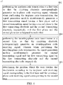
- the operations of the touch controller 16 can be summarized into a process 40, which is shown in FIG. 4 .
- the process 40 includes the steps as follows.
- the first phase of the first transmitting signal TX a and the second phase of the second transmitting signal TX b are not kept orthogonal to each other; for example, there is a phase difference of (90°+ ⁇ ) between the phase of the first transmitting signal TX a and the phase of the second transmitting signal TX b .
- ⁇ can be any value between 0-360 degrees; for example, when ⁇ equals 270 degrees, the phase of the first transmitting signal TX a and the phase of the second transmitting signal TX b are substantially the same.
- the first transmitting signal TX a can be expressed as sin(2 ⁇ f c t ) and is transmitted to the first transmitting electrode TE a
- the second transmitting signal TX b can be expressed as cos(2 ⁇ f c t + ⁇ ) and is transmitted to the second transmitting electrode TE b
- the second transmitting signal TX b is transmitted to the first transmitting electrode TE a
- the first transmitting signal TX a is transmitted to the second transmitting electrode TE b .
- the first transmitting signal TX a and the second transmitting signal TX b generate corresponding signal components on the receiving electrode RE n ; if the components of transmitting signals from transmitting electrodes TE 1 ⁇ TE M other than the first transmitting signal TX a and the second transmitting signal TX b are ignored, during the in-phase code transmission, the receiving signal RX n can be expressed as X ⁇ sin(2 ⁇ f c t + ⁇ a + ⁇ x ) +Y ⁇ cos(2 ⁇ f c t + ⁇ b + ⁇ y + ⁇ ), wherein X ⁇ sin(2 ⁇ f c t + ⁇ a + ⁇ x ) is the component corresponding to the first transmitting signal TX a , X represents the amplitude corresponding to the first transmitting signal TX a , ⁇ a represents the amount of the phase change in the first transmitting signal TX a caused by the screen body of the touchscreen 18, and ⁇ x represents the amount of
- the receiving signal RX n can be expressed as X ⁇ cos(2 ⁇ f c t + ⁇ a + ⁇ x + ⁇ ) +Y ⁇ sin(2 ⁇ f c t + ⁇ b + ⁇ y ), wherein X ⁇ cos(2 ⁇ f c t + ⁇ a + ⁇ x + ⁇ ) is the component corresponding to the second transmitting signal TX b , Y ⁇ sin(2 ⁇ f c t + ⁇ b + ⁇ y ) is the component corresponding to the first transmitting signal TX a , and the meanings of X, Y, ⁇ a , ⁇ b , ⁇ x , ⁇ y are the same as those described above in connection with the in-phase code transmission.
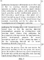
- the operations of the touch controller 16 can be summarized into a process 50, which is shown in FIG. 5 .
- the process 50 includes the steps as follows.
- the present embodiments uses the time and phase modulation implementation when discussing the in-phase code transmission and inverting-phase code transmission
- the present disclosure can use other modulation technologies at the same time; such as, for example, when performing the in-phase code transmission and the inverting-phase code transmission, the following modulation can be performed simultaneously: frequency modulation (e.g., the first transmitting signal TX a and the second transmitting signal TX b may have different frequencies, or the frequency may vary with time), other types of time modulation (e.g., simultaneously performing the pulse-width modulation on the first transmitting signal TX a and the second transmitting signal TX b ) or spatial modulation (e.g., simultaneously performing the spatial vector modulation on the first transmitting signal TX a and the second transmitting signal TX b ), and the like.
- frequency modulation e.g., the first transmitting signal TX a and the second transmitting signal TX b may have different frequencies, or the frequency may vary with time
- other types of time modulation
- the above-mentioned touch controller 16 can be implemented using a semiconductor process; for example, the present application further provides a chip, which includes the touch controller 16, and the chip can be a semiconductor chip implemented using different processes.
Landscapes
- Engineering & Computer Science (AREA)
- General Engineering & Computer Science (AREA)
- Theoretical Computer Science (AREA)
- Human Computer Interaction (AREA)
- Physics & Mathematics (AREA)
- General Physics & Mathematics (AREA)
- Electronic Switches (AREA)
Abstract
Description
- The present application relates to a touch controller and associated chip, touch control system and touch control method; in particular, to a touch controller based on phase modulation, and associated chip, touch control system, and touch control method.
- The touchscreen allows users to use their fingers or stylus to operate and enter information/text/drawings directly on the screen, thereby eliminating the need or trouble for using an input device, such as a keyboard or buttons. Existing touch control technology has been developed to simultaneously (at the same time) use two signals with different frequencies for code transmission on two transmitting electrodes of the touch control system, and the signals carried by different frequencies can be distinguished during the demodulation process. However, this takes up a large bandwidth, and hence, one of the objectives that the industry aims at is how to reduce the signal bandwidth when simultaneously transmitting a plurality of signals to a plurality of electrodes, while at the same time achieve the same performance.
- One purpose of the present application is to disclose a touch controller based on phase modulation and associated chip, touch control system, and touch control method, to address the above-mentioned issues.
- One embodiment of the present application discloses a touch controller, which is configured to determine a position where a user touches a touchscreen, wherein the touchscreen includes a first transmitting electrode, a second transmitting electrode and a receiving electrode. The touch controller includes: a signal generation module, configured to perform an in-phase code transmission at a first time so that the receiving electrode receives an in-phase code receiving signal correspondingly, and perform an inverting-phase code transmission at a second time so that the receiving electrode receives an inverting-phase code receiving signal correspondingly, wherein when performing the in-phase code transmission, the signal generation module simultaneously generates a first transmitting signal having a first phase and a second transmitting signal having a second phase to the first transmitting electrode and the second transmitting electrode, respectively, and when performing the inverting-phase code transmission, the signal generation module simultaneously generates the second transmitting signal and the first transmitting signal to the first transmitting electrode and the second transmitting electrode, respectively; and a demodulation module, configured to determine the position where the user touches the touchscreen according to the in-phase code receiving signal corresponding to the first time and the inverting-phase code receiving signal corresponding to the second time.
- One embodiment of the present application discloses a chip, and the chip includes the above-mentioned touch controller.
- One embodiment of the present application discloses a touch control system, which includes: a touchscreen, including a first transmitting electrode, a second transmitting electrode and a receiving electrode, wherein the receiving electrode is coupled to the first transmitting electrode and the second transmitting electrode; and the above-mentioned touch controller.
- One embodiment of the present application discloses a touch control method, configured to determine a position where a user touches a touchscreen, wherein the touchscreen includes a first transmitting electrode, a second transmitting electrode and a receiving electrode, wherein the touch control method includes: performing an in-phase code transmission at a first time so that the receiving electrode receives an in-phase code receiving signal correspondingly, wherein when performing the in-phase code transmission, the signal generation module simultaneously generates a first transmitting signal having a first phase and a second transmitting signal having a second phase to the first transmitting electrode and the second transmitting electrode, respectively; performing an inverting-phase code transmission at a second time so that the receiving electrode receives an inverting-phase code receiving signal correspondingly, wherein when performing the inverting-phase code transmission, the signal generation module simultaneously generates the second transmitting signal and the first transmitting signal to the first transmitting electrode and the second transmitting electrode, respectively; and time determining the position where the user touches the touchscreen according to the in-phase code receiving signal corresponding to the first time and the inverting-phase code receiving signal corresponding to the second.
- Embodiments of the present application uses two signals with different phases to perform code transmission on two transmitting electrodes of the touch control system, and the two signals with different phases can perform code transmission on the two transmitting electrodes of the touch control system by swapping or not swapping with each other at different time points, thereby obtaining more precise coordinates.
-
-
FIG. 1 is a schematic diagram illustrating a touch control system according to one embodiment of the present application. -
FIG. 2 is a schematic diagram illustrating a signal generation module according to one embodiment of the present application. -
FIG. 3 is a schematic diagram illustrating a code transmission process of a touch control system according to one embodiment of the present application. -
FIG. 4 is a schematic block diagram illustrating a touch control method according to the first embodiment of the present application. -
FIG. 5 is a schematic block diagram illustrating a touch control method according to the second embodiment of the present application. - Reference numerals used is the drawings are summarized below:
- 10
- Touch control system
- 12
- Signal generation module
- 14, 24
- Demodulation module
- 16
- Touch controller
- 18
- Touchscreen
- 240
- Frequency-mixing and integration unit
- 242
- Decoding unit
- 40, 50
- Process
- 402, 404, 406, 502, 504, 506
- Step
- The following disclosure provides many different embodiments, or examples, for implementing different features of the invention. Specific examples of components and arrangements are described below to simplify the present disclosure. As could be appreciated, these are, of course, merely examples and are not intended to be limiting. For example, the formation of a first feature over or on a second feature in the description that follows may include embodiments in which the first and the second features are formed in direct contact, and may also include embodiments in which additional features may be formed between the first and the second features, such that the first and the second features may not be in direct contact. In addition, the present disclosure may repeat reference numerals and/or letters in the various examples. This repetition is for the purpose of simplicity and clarity and does not in itself dictate a relationship between the various embodiments and/or configurations discussed.
- Further, spatially relative terms, such as "beneath," "below," "lower," "above," "upper," and the like, may be used herein for the ease of the description to describe one element or feature's relationship with respect to another element(s) or feature(s) as illustrated in the drawings. The spatially relative terms are intended to encompass different orientations of the device in use or operation in addition to the orientation depicted in the figures. The apparatus may be otherwise oriented (e.g., rotated by 90 degrees or at other orientations) and the spatially relative descriptors used herein may likewise be interpreted accordingly.
- Notwithstanding that the numerical ranges and parameters setting forth the broad scope of the invention are approximations, the numerical values set forth in the specific examples are reported as precisely as possible. Any numerical value, however, inherently contains certain errors necessarily resulting from the standard deviation found in the respective testing measurements. Also, as used herein, the term "about" generally means within 10%, 5%, 1%, or 0.5% of a given value or range. Alternatively, the term "about" means within an acceptable standard error of the mean when considered by one of ordinary skill in the art. As could be appreciated, other than in the operating/working examples, or unless otherwise expressly specified, all of the numerical ranges, amounts, values and percentages such as those for quantities of materials, durations of times, temperatures, operating conditions, ratios of amounts, and the likes thereof disclosed herein should be understood as modified in all instances by the term "about." Accordingly, unless indicated to the contrary, the numerical parameters set forth in the present disclosure and attached claims are approximations that can vary as desired. At the very least, each numerical parameter should at least be construed considering the number of reported significant digits and by applying ordinary rounding techniques. Ranges can be expressed herein as from one endpoint to another endpoint or between two endpoints. All ranges disclosed herein are inclusive of the endpoints, unless specified otherwise.
- Referring to
FIG. 1 , which is a schematic diagram illustrating atouch control system 10 according to embodiments of the present application. Thetouch control system 10 includes atouchscreen 18 and atouch controller 16, wherein thetouchscreen 18 includes transmitting electrodes TE1∼TEM and receiving electrodes RE1∼REN, wherein the transmitting electrodes TE1∼TEM and receiving electrodes RE1∼REN are arranged perpendicular to each other, and each of the receiving electrodes RE1∼REN is coupled to each of the transmitting electrodes TE1∼TEM Thetouch controller 16 includes asignal generation module 12 and ademodulation module 14. Thesignal generation module 12 is coupled to the transmitting electrodes TE1∼TEM, and thedemodulation module 14 is coupled to the receiving electrodes RE1∼REN. - The present disclosure does not require the use of a pre-stage to obtain the screen body information of the
touchscreen 18 in a no-touch situation, but can receive a user's touch directly and use thesignal generation module 12 of thetouch controller 16 for code transmission and using the demodulation from thedemodulation module 14 to generate a demodulation result. Thetouch control system 10 can determine the position where the touch event takes place based on the result of the demodulation calculation. The detailed operation means of thetouch controller 16 will be described below. - In the present disclosure, sensing can be performed on at least two transmitting electrodes simultaneously, for example, a first transmitting electrode TEa in the transmitting electrodes TE1∼TEM and a second transmitting signal TXb can be paired as a group for simultaneous sensing, wherein, the first transmitting electrode TEa and the second transmitting electrode TEb may be two consecutive electrodes (i.e., adjacent to each other) or two non-consecutive electrodes (that is at least other transmitting electrode between the first transmitting electrode TEa and the second transmitting electrode TEb). The code transmission of the
signal generation module 12 can be divided into the in-phase code transmission and inverting-phase code transmission; when thesignal generation module 12 performs in-phase code transmission, a first transmitting signal TXa is inputted to the first transmitting electrode TEa, and, a second transmitting signal TXb is inputted to the second transmitting electrode TEb, simultaneously, so that the receiving electrodes RE1∼REN receive in-phase code receiving signals correspondingly, wherein the first transmitting signal TXa and the second transmitting signal TXb are signals having different phases; specifically, in the present embodiment, the first transmitting signal TXa and the second transmitting signal TXb have the same frequency and amplitude, but have different phases. When thesignal generation module 12 performs the inverting-phase code transmission, the first transmitting signal TXa and the second transmitting signal TXb are swapped with each other, so that the receiving electrodes RE1∼REN receive the inverting-phase code receiving signal correspondingly. Specifically, in the present embodiment, the first transmitting signal TXa may have a frequency fc and a first phase, and the second transmitting signal TXb may have a frequency fc and a second phase, wherein a phase difference between the first phase and the second phase is not zero. The in-phase code transmission and inverting-phase code transmission takes place alternatingly; that is after one in-phase code transmission, one inverting-phase code transmission takes place immediately, followed by one in-phase code transmission immediately, and so on. - The
demodulation module 14 can receives the receiving signal from the receiving electrodes RE1∼REN; for example, in the present embodiment, thedemodulation module 14 can receive the receiving signal from one receiving electrode of the receiving electrode RE1∼REN one at a time in a specific time order. To facilitate the discussion, the following paragraphs use the receiving signal RXn from one receiving electrode REn of the receiving electrodes RE1∼REN as an example to explain how thedemodulation module 14 receives the receiving signal. - The
demodulation module 14 is configured to determine the position where the user touches the touchscreen according to two consecutive receiving signal RXn (one corresponding to the in-phase code transmission, and the other corresponding to the inverting-phase code transmission). Specifically, after thedemodulation module 14 receives the receiving signal RXn, it performs demodulation calculation on the receiving signal RXn; that is, it calculates and outputs amplitude corresponding to the first phase and amplitude corresponding to the second phase from the receiving signal RXn according to the receiving signal RXn. In this way, thetouch control system 10 can thus determine the capacitance (or the change in the capacitance) of a capacitive node formed between the first transmitting electrode TEa and the receiving electrode REn, and determine the capacitance (or the change in the capacitance) between the second transmitting electrode TEb and the receiving electrode REn according to the second amplitude B, so as to determine whether there is a touch event taking place and determine the position where the user touches the touchscreen. - The
demodulation module 14 receives one receiving signal from one receiving electrode at a time in a specified order, and performs demodulation calculation on the receiving signal; however, the present embodiment is not limited thereto, and the present demodulation module can receive a plurality of receiving signals from a plurality of receiving electrodes at once and performs demodulation calculation on these receiving signals respectively. Since the principles for performing demodulation calculation on a plurality of receiving signals respectively are the same as those for performing demodulation calculation on a single receiving signal, the following example will be illustrated by the demodulation module receiving one receiving signal from one receiving electrode at a time and performing demodulation calculation on that receiving signal. - In the first embodiment of the present disclosure, the first phase of the first transmitting signal TXa and the second phase of the second transmitting signal TXb are kept orthogonal to each other; during the in-phase code transmission, the first transmitting signal TXa can be expressed as sin(2 πfct) and is transmitted to the first transmitting electrode TEa, the second transmitting signal TXb can be expressed as cos(2 πfct) and is transmitted to the second transmitting electrode TEb; during the inverting-phase code transmission, the second transmitting signal TXb is transmitted to the first transmitting electrode TEa, and the first transmitting signal TXa is transmitted to the second transmitting electrode TEb. The first transmitting signal TXa and the second transmitting signal TXb generate corresponding signal components correspondingly on the receiving electrode REn; if the components of transmitting signals other than the first transmitting signal TXa and the second transmitting signal TXb on the transmitting electrodes TE1∼TEM are ignored, during the in-phase code transmission, the receiving signal RXn can be expressed as X·sin(2 πfct+θa +θx ) +Y·cos(2 πfct+θb +θy ), wherein X·sin(2 πfct+θa +θx ) is the component corresponding to the first transmitting signal TXa, X represents the amplitude corresponding to the first transmitting signal TXa; specifically, when the finger touches a position on the touchscreen corresponding to the first transmitting electrode TEa, X also includes the change in the amplitude of the first transmitting signal TXa after the touching, θa represents the amount of the phase change in the first transmitting signal TXa caused by the screen body of the
touchscreen 18, θx represents the amount of the phase change in the first transmitting signal TXa caused by the finger touching the screen body of thetouchscreen 18; Y·cos(2 πfct+θb ) is the component corresponding to the second transmitting signal TXb, Y represents the amplitude corresponding to the second transmitting signal TXb; similarly, when the finger touches a position on the touchscreen corresponding to the second transmitting electrode TEb, Y also includes the change in the amplitude of the second transmitting signal TXb after the touching, θb represents the amount of the phase change in the second transmitting signal TXb caused by the screen body of thetouchscreen 18, θy represents the amount of the phase change in the second transmitting signal TXb caused by the finger touching the screen body of thetouchscreen 18. While during the inverting-phase code transmission, the receiving signal RXn can be expressed as X·cos(2 πfct+θa +θx ) +Y·sin(2 πfct+θb +θy ), wherein X·cos(2 πfct+θa +θx ) is the component corresponding to the second transmitting signal TXb, Y·sin(2 πfct+θb +θy ) is the component corresponding to the first transmitting signal TXa, and the meanings of X, Y, θa, θb, θx, θy are the same as those described above in connection with the in-phase code transmission. - Referring to
FIG. 2 , which is a schematic diagram illustrating ademodulation module 24 according to embodiments of the present application. Thedemodulation module 24 can be used as a specific implementation of thedemodulation module 14, wherein thedemodulation module 24 includes a frequency-mixing andintegration unit 240 and adecoding unit 242. The frequency-mixing andintegration unit 240 includes mixers MX1, MX2 and integrators INT1, INT2, wherein the mixer MX1 and the integrator INT1 are configured to use a local signal sin(2 πfct) to perform frequency mixing and integration on the receiving signal RXn, to output an in-phase component of the receiving signal RXn, and the mixer MX2 and integrator INT2 are configured to use a local signal cos(2 πfct) to perform frequency mixing and integration on the receiving signal RXn, to output a quadrature component of the receiving signal RXn. - Referring to
FIG. 3 , which is a schematic diagram illustrating a code transmission process performed by ademodulation module 24 according to embodiments of the present application. Thesignal generation module 12 performs an in-phase code transmission on the transmitting electrodes TEa and TEb at time points T1, T3, T5, T7; and performs an inverting-phase code transmission on transmitting electrodes TEa and TEb at time points T2, T4, T6, T8. Thedecoding unit 242 reports point at the time point T2; that is, it uses the information obtained at time points T1 and T2 to generate a demodulation result; thedecoding unit 242 reports point at the time point T3; that is, it uses the information obtained at the time points T2 and T3 to generate the demodulation result, and so one. - Reference is made to both
FIG. 2 andFIG. 3 ; during the in-phase code transmission, the following equation is obtained after the receiving signal RXn= X·sin(2 πfct+θa +θx )+Y·cos(2 πfct+θb +θy ) passes the mixer MX1 and the integrator INT1:

- During the inverting-phase code transmission, the following equation is obtained after the receiving signal RXn= X·cos(2 πfct+θa +θx ) +Y·sin(2 πfct+θb +θy ) passes the mixer MX1 and the integrator INT1:



- In the above-mentioned first embodiment, the operations of the
touch controller 16 can be summarized into aprocess 40, which is shown inFIG. 4 . Theprocess 40 includes the steps as follows. - Step 402: performing the in-phase code transmission at a first time, so that the receiving electrode REn correspondingly receives an in-phase code receiving signal RXn= X·sin(2 πfct+θa +θx ) +Y·cos(2 πfct+θb +θy ), wherein when performing the in-phase code transmission, the
signal generation module 12 simultaneously generates a first transmitting signal having a first phase TXa= sin(2 πfct) and a second transmitting signal having a second phase TXb= cos(2 πfct) to the first transmitting electrode TEa and the second transmitting electrode TEb, respectively, and the first phase and the second phase are orthogonal to each other. - Step 404: performing the inverting-phase code transmission at a second time, so that the receiving electrode REn correspondingly receives an inverting-phase code receiving signal RXn= X·cos(2 πfct+θa +θx ) +Y·sin(2 πfct+θb +θy ), wherein when performing the inverting-phase code transmission, the
signal generation module 12 simultaneously generates the second transmitting signal TXb= cos(2 πfct) and the first transmitting signal TXa= sin(2 πfct) to the first transmitting electrode TEa and the second transmitting electrode TEb, respectively. - Step 406: determining the position where the user touches the touchscreen according to the in-phase code receiving signal RXn= X·sin(2 πfct+θa +θx ) +Y·cos(2 πfct+θb +θy ) corresponding to the first time and the inverting-phase code receiving signal RXn= X·cos(2 πfct+θa +θx ) +Y·sin(2 πfct+θb +θy ) corresponding to the second time.
- Detailed descriptions for the
process 40 can be found in preceding relevant paragraphs, and are hence omitted herein for the sake of brevity. - In the second embodiment of the present disclosure, the first phase of the first transmitting signal TXa and the second phase of the second transmitting signal TXb are not kept orthogonal to each other; for example, there is a phase difference of (90°+Δ) between the phase of the first transmitting signal TXa and the phase of the second transmitting signal TXb. In this case, Δ can be any value between 0-360 degrees; for example, when Δ equals 270 degrees, the phase of the first transmitting signal TXa and the phase of the second transmitting signal TXb are substantially the same. During the in-phase code transmission, the first transmitting signal TXa can be expressed as sin(2 πfct) and is transmitted to the first transmitting electrode TEa, and the second transmitting signal TXb can be expressed as cos(2 πfct+Δ) and is transmitted to the second transmitting electrode TEb; during the inverting-phase code transmission, the second transmitting signal TXb is transmitted to the first transmitting electrode TEa, and the first transmitting signal TXa is transmitted to the second transmitting electrode TEb. The first transmitting signal TXa and the second transmitting signal TXb generate corresponding signal components on the receiving electrode REn; if the components of transmitting signals from transmitting electrodes TE1∼TEM other than the first transmitting signal TXa and the second transmitting signal TXb are ignored, during the in-phase code transmission, the receiving signal RXn can be expressed as X·sin(2 πfct+θa +θx ) +Y·cos(2 πfct+θb +θy +Δ), wherein X·sin(2 πfct+θa +θx ) is the component corresponding to the first transmitting signal TXa, X represents the amplitude corresponding to the first transmitting signal TXa, θa represents the amount of the phase change in the first transmitting signal TXa caused by the screen body of the
touchscreen 18, and θx represents the amount of the phase change in the first transmitting signal TXa caused by the finger touching the screen body of thetouchscreen 18; Y·cos(2 πfct+θb + Δ) is the component corresponding to the second transmitting signal TXb, Y represents the amplitude corresponding to the second transmitting signal TXb, θb represents the amount of the phase change in the second transmitting signal TXb caused by the screen body of thetouchscreen 18, and θy represents the amount of the phase change in the second transmitting signal TXb caused by the finger touching the screen body of thetouchscreen 18. During the inverting-phase code transmission, the receiving signal RXn can be expressed as X·cos(2 πfct+θa +θx +Δ) +Y·sin(2 πfct+θb +θy ), wherein X·cos(2 πfct+θa +θx +Δ) is the component corresponding to the second transmitting signal TXb, Y·sin(2 πfct+θb +θy ) is the component corresponding to the first transmitting signal TXa, and the meanings of X, Y, θa, θb, θx, θy are the same as those described above in connection with the in-phase code transmission. - Similar to the previous embodiment, reference is made to both
FIG. 2 andFIG. 3 . During the in-phase code transmission, the following equation is obtained after the receiving signal RXn=X·sin(2 πfct+θa +θx ) +Y·cos(2 πfct+θb +θy +Δ) passes the mixer MX1 and the integrator INT1:

- During the inverting-phase code transmission, the following equation is obtained after the receiving signal RXn= X·cos(2 πfct+θa +θx +Δ) +Y·sin(2 πfct+θb +θy ) passes the mixer MX1 and the integrator INT1:


- In the above-mentioned second embodiment, the operations of the
touch controller 16 can be summarized into aprocess 50, which is shown inFIG. 5 . Theprocess 50 includes the steps as follows. - Step 502: performing the in-phase code transmission at a first time, so that the receiving electrode REn correspondingly receives an in-phase code receiving signal RXn= X·sin(2 πfct+θa +θx ) +Y·cos(2 πfct+θb +θy +Δ), wherein when performing the in-phase code transmission, the
signal generation module 12 simultaneously generates a first transmitting signal having a first phase TXa= sin(2 πfct) and a second transmitting signal having a second phase TXb= cos(2 πfct+Δ) to the first transmitting electrode TEa and the second transmitting electrode TEb, respectively, and the first phase and the second phase are not orthogonal to each other. - Step 504: performing the inverting-phase code transmission at a second time, so that the receiving electrode REn correspondingly receives an inverting-phase code receiving signal RXn= X·cos(2 πfct+θa +θx +Δ) +Y·sin(2 πfct+θb +θy ), wherein when performing the inverting-phase code transmission, the
signal generation module 12 simultaneously generates the second transmitting signal TXb= cos(2 πfct+Δ) and the first transmitting signal TXa= sin(2 πfct) to the first transmitting electrode TEa and the second transmitting electrode TEb, respectively. - Step 506: determining the position where the user touches the touchscreen according to the first phase, the second phase and the in-phase code receiving signal RXn= X·sin(2 πfct+θa +θx ) +Y·cos(2 πfct+θb +θy +Δ) corresponding to the first time and the inverting-phase code receiving signal RXn= X·cos(2 πfct+θa +θx +Δ) +Y·sin(2 πfct+θb +θy ) corresponding to the second time.
- Detailed descriptions for the
process 50 can be found in preceding relevant paragraphs, and are hence omitted herein for the sake of brevity. - It should be noted that although the present embodiments uses the time and phase modulation implementation when discussing the in-phase code transmission and inverting-phase code transmission, the present disclosure can use other modulation technologies at the same time; such as, for example, when performing the in-phase code transmission and the inverting-phase code transmission, the following modulation can be performed simultaneously: frequency modulation (e.g., the first transmitting signal TXa and the second transmitting signal TXb may have different frequencies, or the frequency may vary with time), other types of time modulation (e.g., simultaneously performing the pulse-width modulation on the first transmitting signal TXa and the second transmitting signal TXb) or spatial modulation (e.g., simultaneously performing the spatial vector modulation on the first transmitting signal TXa and the second transmitting signal TXb), and the like.
- In some embodiments, the above-mentioned
touch controller 16 can be implemented using a semiconductor process; for example, the present application further provides a chip, which includes thetouch controller 16, and the chip can be a semiconductor chip implemented using different processes. - The foregoing outlines features of several embodiments so that those skilled in the art may better understand various aspects of the present disclosure. Those skilled in the art should appreciate that they may readily use the present disclosure as a basis for designing or modifying other processes and structures for carrying out the same purposes and/or achieving the same advantages of embodiments introduced herein. Those skilled in the art should also realize that such equivalent embodiments still fall within the spirit and scope of the present disclosure, and they may make various changes, substitutions, and alterations thereto without departing from the spirit and scope of the present disclosure.
Claims (19)
- A touch controller, configured to determine a position where a user touches a touchscreen, wherein the touchscreen includes a first transmitting electrode, a second transmitting electrode and a receiving electrode, and the touch controller is characterized by comprising:a signal generation module, configured to perform an in-phase code transmission at a first time so that the receiving electrode receives an in-phase code receiving signal correspondingly, and perform an inverting-phase code transmission at a second time so that the receiving electrode receives an inverting-phase code receiving signal correspondingly, wherein when performing the in-phase code transmission, the signal generation module simultaneously generates a first transmitting signal having a first phase and a second transmitting signal having a second phase to the first transmitting electrode and the second transmitting electrode, respectively, and when performing the inverting-phase code transmission, the signal generation module simultaneously generates the second transmitting signal and the first transmitting signal to the first transmitting electrode and the second transmitting electrode, respectively; anda demodulation module, configured to determine the position where the user touches the touchscreen according to the in-phase code receiving signal corresponding to the first time and the inverting-phase code receiving signal corresponding to the second time.
- The touch controller of claim 1, wherein the first transmitting signal and the second transmitting signal have the same frequency.
- The touch controller of claim 1, wherein the first transmitting signal and the second transmitting signal have the same amplitude.
- The touch controller of claim 1, wherein the first transmitting signal and the second transmitting signal are orthogonal to each other.
- The touch controller of claim 1, wherein the signal generation module is further configured to perform an in-phase code transmission at a third time so that the receiving electrode receives an in-phase code receiving signal correspondingly.
- The touch controller of claim 5, wherein the demodulation module further determines the position where the user touches the touchscreen according to the inverting-phase code receiving signal corresponding to the second time and the in-phase code receiving signal corresponding to the third time.
- The touch controller of claim 1, wherein the first transmitting signal and the second transmitting signal are not orthogonal to each other.
- The touch controller of claim 7, wherein the demodulation module further determines the position where the user touches the touchscreen according to the first phase and the second phase.
- The touch controller of claim 1, wherein the first transmitting electrode and the second transmitting electrode are disposed adjacent to each other.
- A chip, characterized in that, the chip comprises:
the touch controller according to any of claims 1 to 9. - A touch control system, characterized by comprising:a touchscreen, including a first transmitting electrode, a second transmitting electrode and a receiving electrode, wherein the receiving electrode is coupled to the first transmitting electrode and the second transmitting electrode; andthe touch controller according to any of claims 1 to 9.
- A touch control method, configured to determine a position wherein a user touches a touchscreen, wherein the touchscreen includes a first transmitting electrode, a second transmitting electrode and a receiving electrode, and the touch control method is characterized by comprising:performing an in-phase code transmission at a first time so that the receiving electrode receives an in-phase code receiving signal correspondingly, wherein when performing the in-phase code transmission, the signal generation module simultaneously generates a first transmitting signal having a first phase and a second transmitting signal having a second phase to the first transmitting electrode and the second transmitting electrode, respectively;performing an inverting-phase code transmission at a second time so that the receiving electrode receives an inverting-phase code receiving signal correspondingly, wherein when performing the inverting-phase code transmission, the signal generation module simultaneously generates the second transmitting signal and the first transmitting signal to the first transmitting electrode and the second transmitting electrode, respectively; anddetermining the position where the user touches the touchscreen according to the in-phase code receiving signal corresponding to the first time and the inverting-phase code receiving signal corresponding to the second time.
- The touch control method of claim 12, wherein the first transmitting signal and the second transmitting signal have the same frequency.
- The touch control method of claim 12, wherein the first transmitting signal and the second transmitting signal have the same amplitude.
- The touch control method of claim 12, wherein the first transmitting signal and the second transmitting signal are orthogonal to each other.
- The touch control method of claim 12, further comprises:
performing an in-phase code transmission at a third time so that the receiving electrode receives an in-phase code receiving signal correspondingly. - The touch control method of claim 16, further comprising:
determining the position where the user touches the touchscreen according to the inverting-phase code receiving signal corresponding to the second time and the in-phase code receiving signal corresponding to the third time. - The touch control method of claim 12, wherein the first transmitting signal and the second transmitting signal are not orthogonal to each other.
- The touch control method of claim 18, further comprising:
determining the position where the user touches the touchscreen according to the first phase and the second phase.
Applications Claiming Priority (1)
| Application Number | Priority Date | Filing Date | Title |
|---|---|---|---|
| PCT/CN2019/077158 WO2020177096A1 (en) | 2019-03-06 | 2019-03-06 | Touch controller, related chip, touch control system, and touch control method |
Publications (2)
| Publication Number | Publication Date |
|---|---|
| EP3754474A1 true EP3754474A1 (en) | 2020-12-23 |
| EP3754474A4 EP3754474A4 (en) | 2021-09-22 |
Family
ID=72337419
Family Applications (1)
| Application Number | Title | Priority Date | Filing Date |
|---|---|---|---|
| EP19916536.6A Pending EP3754474A4 (en) | 2019-03-06 | 2019-03-06 | TOUCH CONTROL, ASSOCIATED CHIP, TOUCH CONTROL SYSTEM AND TOUCH CONTROL METHOD |
Country Status (4)
| Country | Link |
|---|---|
| US (1) | US11366554B2 (en) |
| EP (1) | EP3754474A4 (en) |
| CN (1) | CN111902799B (en) |
| WO (1) | WO2020177096A1 (en) |
Families Citing this family (2)
| Publication number | Priority date | Publication date | Assignee | Title |
|---|---|---|---|---|
| US11531425B1 (en) * | 2021-11-03 | 2022-12-20 | Synaptics Incorporated | Inter-band harmonics interference mitigation for multi-frequency-region parallel scan |
| CN117369674B (en) * | 2023-10-27 | 2025-06-27 | 敦泰电子(深圳)有限公司 | Touch detection method, touch chip and touch device |
Family Cites Families (11)
| Publication number | Priority date | Publication date | Assignee | Title |
|---|---|---|---|---|
| TWI346929B (en) * | 2006-10-13 | 2011-08-11 | Au Optronics Corp | Gate driver and driving method of liquid crystal display device |
| TWI463382B (en) * | 2009-09-14 | 2014-12-01 | Raydium Semiconductor Corp | Touch sensing apparatus and touch sensing method |
| US9285902B1 (en) * | 2010-08-25 | 2016-03-15 | Parade Technologies, Ltd. | Multi-phase scanning |
| US8729911B2 (en) * | 2011-04-19 | 2014-05-20 | Cypress Semiconductor Corporation | Usage of weighting matrices in multi-phase scanning modes |
| KR101525674B1 (en) * | 2013-09-06 | 2015-06-03 | 삼성전기주식회사 | Touchscreen apparatus and driving method thereof |
| US9933880B2 (en) * | 2014-03-17 | 2018-04-03 | Tactual Labs Co. | Orthogonal signaling touch user, hand and object discrimination systems and methods |
| KR101680939B1 (en) * | 2014-08-29 | 2016-11-29 | 주식회사 동부하이텍 | Method of scanning touch panel and touch integrated circuit for performing the same |
| CN104932741B (en) * | 2015-06-02 | 2018-10-26 | 武汉华星光电技术有限公司 | The scan method of touching signals |
| US10037094B2 (en) * | 2015-10-29 | 2018-07-31 | Novatek Microelectronics Corp. | Carrier touch sensing system capable of performing phase calibration and carrier signal demodulation |
| KR101809917B1 (en) * | 2016-01-29 | 2017-12-21 | 엘지디스플레이 주식회사 | Driving circuit, touch display device, and method for driving the touch display device |
| EP3462293A4 (en) * | 2017-08-01 | 2019-08-07 | Shenzhen Goodix Technology Co., Ltd. | TACTILE CONTACT POSITION DETERMINATION METHOD AND TOUCH CONTROL CHIP |
-
2019
- 2019-03-06 EP EP19916536.6A patent/EP3754474A4/en active Pending
- 2019-03-06 CN CN201980000352.8A patent/CN111902799B/en active Active
- 2019-03-06 WO PCT/CN2019/077158 patent/WO2020177096A1/en not_active Ceased
-
2020
- 2020-09-01 US US17/009,518 patent/US11366554B2/en active Active
Also Published As
| Publication number | Publication date |
|---|---|
| WO2020177096A1 (en) | 2020-09-10 |
| US20200401254A1 (en) | 2020-12-24 |
| US11366554B2 (en) | 2022-06-21 |
| EP3754474A4 (en) | 2021-09-22 |
| CN111902799A (en) | 2020-11-06 |
| CN111902799B (en) | 2023-10-24 |
Similar Documents
| Publication | Publication Date | Title |
|---|---|---|
| US10126884B2 (en) | Asynchronous interference detection in a capacitive sensing system | |
| CN110612508B (en) | Touch controller, demodulation method and touch system | |
| US9529473B2 (en) | Electronic device, electrostatic capacitance sensor and touch panel | |
| JP4938734B2 (en) | Multiple simultaneous frequency detection | |
| US9910529B2 (en) | Method, device, and system for detecting transmitter approaching or touching touch sensitive display | |
| JP5295008B2 (en) | Indicator detection device | |
| US11366554B2 (en) | Touch controller using simultaneously generated transmitting signals with different phases and associated chip, touch control system and touch control method | |
| US9785260B2 (en) | Method, apparatus, and system for detecting transmitter approximating or touching touch sensitive device | |
| CN107885398B (en) | Touch processing device and method thereof | |
| CN109388254B (en) | Active stylus, touch sensor, and signal transmission and sensing method | |
| US20160117047A1 (en) | Multiple controller communication method for active stylus data acquisition | |
| TWI521404B (en) | Method, apparatus, and system for detecting transmitter approximating or touching touch sensitive device | |
| US9069406B2 (en) | Mixer for use in touch panel system and method for processing signals in the mixer | |
| TWI775255B (en) | Touch sensitive processing apparatus and touch system for calculating pressure calibration function and method thereof | |
| CN106708340A (en) | Capacitive touch system based on frequency division multiplexing and operation method thereof | |
| CN103376968B (en) | Method for detecting capacitance value and corresponding touch controller | |
| EP3502854A1 (en) | Non-orthogonal demodulation module, touch-control system and non-orthogonal demodulation method | |
| US10203809B2 (en) | Interference detection | |
| CN106681548A (en) | Touch screen calibration method | |
| US20150029146A1 (en) | Capacitive touchscreen device with multi-touchscreens | |
| US9639201B2 (en) | Touch panel, position sensing method of touch panel, and integrated circuit | |
| CN102570984A (en) | Multi-frequency recursive demodulation method for electrical tomographic systems | |
| US20150130735A1 (en) | Transmitter Set for Concurrent Transmission, Transmitting Method Thereof, and Touch Sensitive System | |
| CN104636009A (en) | Transmitter and transmitting method thereof | |
| Whitney | Wireless communication demonstration in hardware using an exactly solvable chaotic oscillator |
Legal Events
| Date | Code | Title | Description |
|---|---|---|---|
| STAA | Information on the status of an ep patent application or granted ep patent |
Free format text: STATUS: UNKNOWN |
|
| STAA | Information on the status of an ep patent application or granted ep patent |
Free format text: STATUS: THE INTERNATIONAL PUBLICATION HAS BEEN MADE |
|
| PUAI | Public reference made under article 153(3) epc to a published international application that has entered the european phase |
Free format text: ORIGINAL CODE: 0009012 |
|
| STAA | Information on the status of an ep patent application or granted ep patent |
Free format text: STATUS: REQUEST FOR EXAMINATION WAS MADE |
|
| 17P | Request for examination filed |
Effective date: 20200831 |
|
| AK | Designated contracting states |
Kind code of ref document: A1 Designated state(s): AL AT BE BG CH CY CZ DE DK EE ES FI FR GB GR HR HU IE IS IT LI LT LU LV MC MK MT NL NO PL PT RO RS SE SI SK SM TR |
|
| AX | Request for extension of the european patent |
Extension state: BA ME |
|
| A4 | Supplementary search report drawn up and despatched |
Effective date: 20210820 |
|
| RIC1 | Information provided on ipc code assigned before grant |
Ipc: G06F 3/041 20060101ALI20210816BHEP Ipc: G06F 3/044 20060101AFI20210816BHEP |
|
| DAV | Request for validation of the european patent (deleted) | ||
| DAX | Request for extension of the european patent (deleted) | ||
| STAA | Information on the status of an ep patent application or granted ep patent |
Free format text: STATUS: EXAMINATION IS IN PROGRESS |
|
| 17Q | First examination report despatched |
Effective date: 20221104 |