EP3754448A1 - Data fusion method and related device - Google Patents
Data fusion method and related device Download PDFInfo
- Publication number
- EP3754448A1 EP3754448A1 EP19771774.7A EP19771774A EP3754448A1 EP 3754448 A1 EP3754448 A1 EP 3754448A1 EP 19771774 A EP19771774 A EP 19771774A EP 3754448 A1 EP3754448 A1 EP 3754448A1
- Authority
- EP
- European Patent Office
- Prior art keywords
- vehicle
- roadside
- result
- sensing
- target object
- Prior art date
- Legal status (The legal status is an assumption and is not a legal conclusion. Google has not performed a legal analysis and makes no representation as to the accuracy of the status listed.)
- Granted
Links
Images





Classifications
-
- G—PHYSICS
- G05—CONTROLLING; REGULATING
- G05D—SYSTEMS FOR CONTROLLING OR REGULATING NON-ELECTRIC VARIABLES
- G05D1/00—Control of position, course, altitude or attitude of land, water, air or space vehicles, e.g. using automatic pilots
- G05D1/02—Control of position or course in two dimensions
- G05D1/021—Control of position or course in two dimensions specially adapted to land vehicles
- G05D1/0231—Control of position or course in two dimensions specially adapted to land vehicles using optical position detecting means
- G05D1/0238—Control of position or course in two dimensions specially adapted to land vehicles using optical position detecting means using obstacle or wall sensors
- G05D1/024—Control of position or course in two dimensions specially adapted to land vehicles using optical position detecting means using obstacle or wall sensors in combination with a laser
-
- B—PERFORMING OPERATIONS; TRANSPORTING
- B60—VEHICLES IN GENERAL
- B60W—CONJOINT CONTROL OF VEHICLE SUB-UNITS OF DIFFERENT TYPE OR DIFFERENT FUNCTION; CONTROL SYSTEMS SPECIALLY ADAPTED FOR HYBRID VEHICLES; ROAD VEHICLE DRIVE CONTROL SYSTEMS FOR PURPOSES NOT RELATED TO THE CONTROL OF A PARTICULAR SUB-UNIT
- B60W40/00—Estimation or calculation of non-directly measurable driving parameters for road vehicle drive control systems not related to the control of a particular sub unit, e.g. by using mathematical models
- B60W40/02—Estimation or calculation of non-directly measurable driving parameters for road vehicle drive control systems not related to the control of a particular sub unit, e.g. by using mathematical models related to ambient conditions
- B60W40/04—Traffic conditions
-
- G—PHYSICS
- G01—MEASURING; TESTING
- G01S—RADIO DIRECTION-FINDING; RADIO NAVIGATION; DETERMINING DISTANCE OR VELOCITY BY USE OF RADIO WAVES; LOCATING OR PRESENCE-DETECTING BY USE OF THE REFLECTION OR RERADIATION OF RADIO WAVES; ANALOGOUS ARRANGEMENTS USING OTHER WAVES
- G01S13/00—Systems using the reflection or reradiation of radio waves, e.g. radar systems; Analogous systems using reflection or reradiation of waves whose nature or wavelength is irrelevant or unspecified
- G01S13/86—Combinations of radar systems with non-radar systems, e.g. sonar, direction finder
-
- G—PHYSICS
- G01—MEASURING; TESTING
- G01S—RADIO DIRECTION-FINDING; RADIO NAVIGATION; DETERMINING DISTANCE OR VELOCITY BY USE OF RADIO WAVES; LOCATING OR PRESENCE-DETECTING BY USE OF THE REFLECTION OR RERADIATION OF RADIO WAVES; ANALOGOUS ARRANGEMENTS USING OTHER WAVES
- G01S13/00—Systems using the reflection or reradiation of radio waves, e.g. radar systems; Analogous systems using reflection or reradiation of waves whose nature or wavelength is irrelevant or unspecified
- G01S13/86—Combinations of radar systems with non-radar systems, e.g. sonar, direction finder
- G01S13/865—Combination of radar systems with lidar systems
-
- G—PHYSICS
- G01—MEASURING; TESTING
- G01S—RADIO DIRECTION-FINDING; RADIO NAVIGATION; DETERMINING DISTANCE OR VELOCITY BY USE OF RADIO WAVES; LOCATING OR PRESENCE-DETECTING BY USE OF THE REFLECTION OR RERADIATION OF RADIO WAVES; ANALOGOUS ARRANGEMENTS USING OTHER WAVES
- G01S13/00—Systems using the reflection or reradiation of radio waves, e.g. radar systems; Analogous systems using reflection or reradiation of waves whose nature or wavelength is irrelevant or unspecified
- G01S13/86—Combinations of radar systems with non-radar systems, e.g. sonar, direction finder
- G01S13/867—Combination of radar systems with cameras
-
- G—PHYSICS
- G01—MEASURING; TESTING
- G01S—RADIO DIRECTION-FINDING; RADIO NAVIGATION; DETERMINING DISTANCE OR VELOCITY BY USE OF RADIO WAVES; LOCATING OR PRESENCE-DETECTING BY USE OF THE REFLECTION OR RERADIATION OF RADIO WAVES; ANALOGOUS ARRANGEMENTS USING OTHER WAVES
- G01S13/00—Systems using the reflection or reradiation of radio waves, e.g. radar systems; Analogous systems using reflection or reradiation of waves whose nature or wavelength is irrelevant or unspecified
- G01S13/88—Radar or analogous systems specially adapted for specific applications
- G01S13/93—Radar or analogous systems specially adapted for specific applications for anti-collision purposes
- G01S13/931—Radar or analogous systems specially adapted for specific applications for anti-collision purposes of land vehicles
-
- G—PHYSICS
- G01—MEASURING; TESTING
- G01S—RADIO DIRECTION-FINDING; RADIO NAVIGATION; DETERMINING DISTANCE OR VELOCITY BY USE OF RADIO WAVES; LOCATING OR PRESENCE-DETECTING BY USE OF THE REFLECTION OR RERADIATION OF RADIO WAVES; ANALOGOUS ARRANGEMENTS USING OTHER WAVES
- G01S17/00—Systems using the reflection or reradiation of electromagnetic waves other than radio waves, e.g. lidar systems
- G01S17/88—Lidar systems specially adapted for specific applications
- G01S17/93—Lidar systems specially adapted for specific applications for anti-collision purposes
- G01S17/931—Lidar systems specially adapted for specific applications for anti-collision purposes of land vehicles
-
- G—PHYSICS
- G01—MEASURING; TESTING
- G01S—RADIO DIRECTION-FINDING; RADIO NAVIGATION; DETERMINING DISTANCE OR VELOCITY BY USE OF RADIO WAVES; LOCATING OR PRESENCE-DETECTING BY USE OF THE REFLECTION OR RERADIATION OF RADIO WAVES; ANALOGOUS ARRANGEMENTS USING OTHER WAVES
- G01S7/00—Details of systems according to groups G01S13/00, G01S15/00, G01S17/00
- G01S7/003—Transmission of data between radar, sonar or lidar systems and remote stations
-
- G—PHYSICS
- G01—MEASURING; TESTING
- G01S—RADIO DIRECTION-FINDING; RADIO NAVIGATION; DETERMINING DISTANCE OR VELOCITY BY USE OF RADIO WAVES; LOCATING OR PRESENCE-DETECTING BY USE OF THE REFLECTION OR RERADIATION OF RADIO WAVES; ANALOGOUS ARRANGEMENTS USING OTHER WAVES
- G01S7/00—Details of systems according to groups G01S13/00, G01S15/00, G01S17/00
- G01S7/02—Details of systems according to groups G01S13/00, G01S15/00, G01S17/00 of systems according to group G01S13/00
- G01S7/40—Means for monitoring or calibrating
- G01S7/4004—Means for monitoring or calibrating of parts of a radar system
- G01S7/4026—Antenna boresight
-
- G—PHYSICS
- G05—CONTROLLING; REGULATING
- G05D—SYSTEMS FOR CONTROLLING OR REGULATING NON-ELECTRIC VARIABLES
- G05D1/00—Control of position, course, altitude or attitude of land, water, air or space vehicles, e.g. using automatic pilots
- G05D1/02—Control of position or course in two dimensions
- G05D1/021—Control of position or course in two dimensions specially adapted to land vehicles
- G05D1/0212—Control of position or course in two dimensions specially adapted to land vehicles with means for defining a desired trajectory
-
- G—PHYSICS
- G05—CONTROLLING; REGULATING
- G05D—SYSTEMS FOR CONTROLLING OR REGULATING NON-ELECTRIC VARIABLES
- G05D1/00—Control of position, course, altitude or attitude of land, water, air or space vehicles, e.g. using automatic pilots
- G05D1/02—Control of position or course in two dimensions
- G05D1/021—Control of position or course in two dimensions specially adapted to land vehicles
- G05D1/0212—Control of position or course in two dimensions specially adapted to land vehicles with means for defining a desired trajectory
- G05D1/0221—Control of position or course in two dimensions specially adapted to land vehicles with means for defining a desired trajectory involving a learning process
-
- G—PHYSICS
- G05—CONTROLLING; REGULATING
- G05D—SYSTEMS FOR CONTROLLING OR REGULATING NON-ELECTRIC VARIABLES
- G05D1/00—Control of position, course, altitude or attitude of land, water, air or space vehicles, e.g. using automatic pilots
- G05D1/02—Control of position or course in two dimensions
- G05D1/021—Control of position or course in two dimensions specially adapted to land vehicles
- G05D1/0212—Control of position or course in two dimensions specially adapted to land vehicles with means for defining a desired trajectory
- G05D1/0223—Control of position or course in two dimensions specially adapted to land vehicles with means for defining a desired trajectory involving speed control of the vehicle
-
- G—PHYSICS
- G05—CONTROLLING; REGULATING
- G05D—SYSTEMS FOR CONTROLLING OR REGULATING NON-ELECTRIC VARIABLES
- G05D1/00—Control of position, course, altitude or attitude of land, water, air or space vehicles, e.g. using automatic pilots
- G05D1/02—Control of position or course in two dimensions
- G05D1/021—Control of position or course in two dimensions specially adapted to land vehicles
- G05D1/0212—Control of position or course in two dimensions specially adapted to land vehicles with means for defining a desired trajectory
- G05D1/0225—Control of position or course in two dimensions specially adapted to land vehicles with means for defining a desired trajectory involving docking at a fixed facility, e.g. base station or loading bay
-
- G—PHYSICS
- G05—CONTROLLING; REGULATING
- G05D—SYSTEMS FOR CONTROLLING OR REGULATING NON-ELECTRIC VARIABLES
- G05D1/00—Control of position, course, altitude or attitude of land, water, air or space vehicles, e.g. using automatic pilots
- G05D1/02—Control of position or course in two dimensions
- G05D1/021—Control of position or course in two dimensions specially adapted to land vehicles
- G05D1/0231—Control of position or course in two dimensions specially adapted to land vehicles using optical position detecting means
- G05D1/0242—Control of position or course in two dimensions specially adapted to land vehicles using optical position detecting means using non-visible light signals, e.g. IR or UV signals
-
- G—PHYSICS
- G05—CONTROLLING; REGULATING
- G05D—SYSTEMS FOR CONTROLLING OR REGULATING NON-ELECTRIC VARIABLES
- G05D1/00—Control of position, course, altitude or attitude of land, water, air or space vehicles, e.g. using automatic pilots
- G05D1/02—Control of position or course in two dimensions
- G05D1/021—Control of position or course in two dimensions specially adapted to land vehicles
- G05D1/0231—Control of position or course in two dimensions specially adapted to land vehicles using optical position detecting means
- G05D1/0246—Control of position or course in two dimensions specially adapted to land vehicles using optical position detecting means using a video camera in combination with image processing means
- G05D1/0251—Control of position or course in two dimensions specially adapted to land vehicles using optical position detecting means using a video camera in combination with image processing means extracting 3D information from a plurality of images taken from different locations, e.g. stereo vision
-
- G—PHYSICS
- G05—CONTROLLING; REGULATING
- G05D—SYSTEMS FOR CONTROLLING OR REGULATING NON-ELECTRIC VARIABLES
- G05D1/00—Control of position, course, altitude or attitude of land, water, air or space vehicles, e.g. using automatic pilots
- G05D1/02—Control of position or course in two dimensions
- G05D1/021—Control of position or course in two dimensions specially adapted to land vehicles
- G05D1/0255—Control of position or course in two dimensions specially adapted to land vehicles using acoustic signals, e.g. ultra-sonic singals
-
- G—PHYSICS
- G05—CONTROLLING; REGULATING
- G05D—SYSTEMS FOR CONTROLLING OR REGULATING NON-ELECTRIC VARIABLES
- G05D1/00—Control of position, course, altitude or attitude of land, water, air or space vehicles, e.g. using automatic pilots
- G05D1/02—Control of position or course in two dimensions
- G05D1/021—Control of position or course in two dimensions specially adapted to land vehicles
- G05D1/0257—Control of position or course in two dimensions specially adapted to land vehicles using a radar
-
- G—PHYSICS
- G05—CONTROLLING; REGULATING
- G05D—SYSTEMS FOR CONTROLLING OR REGULATING NON-ELECTRIC VARIABLES
- G05D1/00—Control of position, course, altitude or attitude of land, water, air or space vehicles, e.g. using automatic pilots
- G05D1/02—Control of position or course in two dimensions
- G05D1/021—Control of position or course in two dimensions specially adapted to land vehicles
- G05D1/0259—Control of position or course in two dimensions specially adapted to land vehicles using magnetic or electromagnetic means
-
- G—PHYSICS
- G05—CONTROLLING; REGULATING
- G05D—SYSTEMS FOR CONTROLLING OR REGULATING NON-ELECTRIC VARIABLES
- G05D1/00—Control of position, course, altitude or attitude of land, water, air or space vehicles, e.g. using automatic pilots
- G05D1/02—Control of position or course in two dimensions
- G05D1/021—Control of position or course in two dimensions specially adapted to land vehicles
- G05D1/0276—Control of position or course in two dimensions specially adapted to land vehicles using signals provided by a source external to the vehicle
- G05D1/0278—Control of position or course in two dimensions specially adapted to land vehicles using signals provided by a source external to the vehicle using satellite positioning signals, e.g. GPS
-
- G—PHYSICS
- G05—CONTROLLING; REGULATING
- G05D—SYSTEMS FOR CONTROLLING OR REGULATING NON-ELECTRIC VARIABLES
- G05D1/00—Control of position, course, altitude or attitude of land, water, air or space vehicles, e.g. using automatic pilots
- G05D1/02—Control of position or course in two dimensions
- G05D1/021—Control of position or course in two dimensions specially adapted to land vehicles
- G05D1/0276—Control of position or course in two dimensions specially adapted to land vehicles using signals provided by a source external to the vehicle
- G05D1/028—Control of position or course in two dimensions specially adapted to land vehicles using signals provided by a source external to the vehicle using a RF signal
-
- G—PHYSICS
- G05—CONTROLLING; REGULATING
- G05D—SYSTEMS FOR CONTROLLING OR REGULATING NON-ELECTRIC VARIABLES
- G05D1/00—Control of position, course, altitude or attitude of land, water, air or space vehicles, e.g. using automatic pilots
- G05D1/02—Control of position or course in two dimensions
- G05D1/021—Control of position or course in two dimensions specially adapted to land vehicles
- G05D1/0276—Control of position or course in two dimensions specially adapted to land vehicles using signals provided by a source external to the vehicle
- G05D1/0285—Control of position or course in two dimensions specially adapted to land vehicles using signals provided by a source external to the vehicle using signals transmitted via a public communication network, e.g. GSM network
-
- G—PHYSICS
- G05—CONTROLLING; REGULATING
- G05D—SYSTEMS FOR CONTROLLING OR REGULATING NON-ELECTRIC VARIABLES
- G05D1/00—Control of position, course, altitude or attitude of land, water, air or space vehicles, e.g. using automatic pilots
- G05D1/60—Intended control result
- G05D1/646—Following a predefined trajectory, e.g. a line marked on the floor or a flight path
-
- G—PHYSICS
- G06—COMPUTING OR CALCULATING; COUNTING
- G06F—ELECTRIC DIGITAL DATA PROCESSING
- G06F18/00—Pattern recognition
- G06F18/20—Analysing
- G06F18/22—Matching criteria, e.g. proximity measures
-
- G—PHYSICS
- G06—COMPUTING OR CALCULATING; COUNTING
- G06F—ELECTRIC DIGITAL DATA PROCESSING
- G06F18/00—Pattern recognition
- G06F18/20—Analysing
- G06F18/25—Fusion techniques
-
- G—PHYSICS
- G06—COMPUTING OR CALCULATING; COUNTING
- G06F—ELECTRIC DIGITAL DATA PROCESSING
- G06F18/00—Pattern recognition
- G06F18/20—Analysing
- G06F18/25—Fusion techniques
- G06F18/251—Fusion techniques of input or preprocessed data
-
- G—PHYSICS
- G06—COMPUTING OR CALCULATING; COUNTING
- G06V—IMAGE OR VIDEO RECOGNITION OR UNDERSTANDING
- G06V10/00—Arrangements for image or video recognition or understanding
- G06V10/70—Arrangements for image or video recognition or understanding using pattern recognition or machine learning
- G06V10/77—Processing image or video features in feature spaces; using data integration or data reduction, e.g. principal component analysis [PCA] or independent component analysis [ICA] or self-organising maps [SOM]; Blind source separation
- G06V10/80—Fusion, i.e. combining data from various sources at the sensor level, preprocessing level, feature extraction level or classification level
- G06V10/803—Fusion, i.e. combining data from various sources at the sensor level, preprocessing level, feature extraction level or classification level of input or preprocessed data
-
- G—PHYSICS
- G06—COMPUTING OR CALCULATING; COUNTING
- G06V—IMAGE OR VIDEO RECOGNITION OR UNDERSTANDING
- G06V20/00—Scenes; Scene-specific elements
- G06V20/50—Context or environment of the image
- G06V20/56—Context or environment of the image exterior to a vehicle by using sensors mounted on the vehicle
-
- G—PHYSICS
- G01—MEASURING; TESTING
- G01S—RADIO DIRECTION-FINDING; RADIO NAVIGATION; DETERMINING DISTANCE OR VELOCITY BY USE OF RADIO WAVES; LOCATING OR PRESENCE-DETECTING BY USE OF THE REFLECTION OR RERADIATION OF RADIO WAVES; ANALOGOUS ARRANGEMENTS USING OTHER WAVES
- G01S13/00—Systems using the reflection or reradiation of radio waves, e.g. radar systems; Analogous systems using reflection or reradiation of waves whose nature or wavelength is irrelevant or unspecified
- G01S13/88—Radar or analogous systems specially adapted for specific applications
- G01S13/93—Radar or analogous systems specially adapted for specific applications for anti-collision purposes
- G01S13/931—Radar or analogous systems specially adapted for specific applications for anti-collision purposes of land vehicles
- G01S2013/9316—Radar or analogous systems specially adapted for specific applications for anti-collision purposes of land vehicles combined with communication equipment with other vehicles or with base stations
-
- G—PHYSICS
- G01—MEASURING; TESTING
- G01S—RADIO DIRECTION-FINDING; RADIO NAVIGATION; DETERMINING DISTANCE OR VELOCITY BY USE OF RADIO WAVES; LOCATING OR PRESENCE-DETECTING BY USE OF THE REFLECTION OR RERADIATION OF RADIO WAVES; ANALOGOUS ARRANGEMENTS USING OTHER WAVES
- G01S13/00—Systems using the reflection or reradiation of radio waves, e.g. radar systems; Analogous systems using reflection or reradiation of waves whose nature or wavelength is irrelevant or unspecified
- G01S13/88—Radar or analogous systems specially adapted for specific applications
- G01S13/93—Radar or analogous systems specially adapted for specific applications for anti-collision purposes
- G01S13/931—Radar or analogous systems specially adapted for specific applications for anti-collision purposes of land vehicles
- G01S2013/932—Radar or analogous systems specially adapted for specific applications for anti-collision purposes of land vehicles using own vehicle data, e.g. ground speed, steering wheel direction
-
- G—PHYSICS
- G01—MEASURING; TESTING
- G01S—RADIO DIRECTION-FINDING; RADIO NAVIGATION; DETERMINING DISTANCE OR VELOCITY BY USE OF RADIO WAVES; LOCATING OR PRESENCE-DETECTING BY USE OF THE REFLECTION OR RERADIATION OF RADIO WAVES; ANALOGOUS ARRANGEMENTS USING OTHER WAVES
- G01S13/00—Systems using the reflection or reradiation of radio waves, e.g. radar systems; Analogous systems using reflection or reradiation of waves whose nature or wavelength is irrelevant or unspecified
- G01S13/88—Radar or analogous systems specially adapted for specific applications
- G01S13/93—Radar or analogous systems specially adapted for specific applications for anti-collision purposes
- G01S13/931—Radar or analogous systems specially adapted for specific applications for anti-collision purposes of land vehicles
- G01S2013/9323—Alternative operation using light waves
-
- G—PHYSICS
- G06—COMPUTING OR CALCULATING; COUNTING
- G06V—IMAGE OR VIDEO RECOGNITION OR UNDERSTANDING
- G06V20/00—Scenes; Scene-specific elements
- G06V20/50—Context or environment of the image
- G06V20/52—Surveillance or monitoring of activities, e.g. for recognising suspicious objects
- G06V20/54—Surveillance or monitoring of activities, e.g. for recognising suspicious objects of traffic, e.g. cars on the road, trains or boats
-
- G—PHYSICS
- G06—COMPUTING OR CALCULATING; COUNTING
- G06V—IMAGE OR VIDEO RECOGNITION OR UNDERSTANDING
- G06V2201/00—Indexing scheme relating to image or video recognition or understanding
- G06V2201/07—Target detection
Definitions
- the present invention relates to the self-driving field, and in particular, to a data fusion method and a related device.
- Road environment sensing is a primary task for implementing self-driving.
- a self-driving vehicle can dodge other vehicles, pedestrians, or the like on a road and implement safe driving only after sensing a road environment.
- the self-driving vehicle in the prior art detects the other vehicles, pedestrians, or the like on the road by using a vehicle sensing apparatus installed on the vehicle, thereby sensing the road environment.
- a sensing range of the vehicle sensing apparatus in the prior art is relatively narrow, and can hardly meet a requirement for self-driving.
- Embodiments of this application provide a data fusion method and a related device to implement overlapping between a sensing range of a roadside sensing apparatus and a sensing range of a vehicle sensing apparatus, so that the sensing range is effectively extended.
- a data fusion method is provided and may be applied to a vehicle device side or a roadside device side, where the method includes:
- the confidence factor is determined based on a sensing apparatus parameter, a sensing distance of the target object, and a sensing angle of the target object together.
- the confidence factor may be obtained by comprehensively considering confidence of the plurality of sensors.
- the confidence of the plurality of sensors may be comprehensively considered in a manner of weighting or averaging.
- the vehicle result set includes at least one vehicle result unit, a one-to-one correspondence exists between the at least one vehicle result unit and at least one target object, and each vehicle result unit in the at least one vehicle result unit is used to describe a feature of a corresponding target object from a multidimensional angle.
- any vehicle result unit in the at least one vehicle result unit is expressed as vehiclej (p vj , v vj , s vj , c vj ), where p vj indicates a position of the target object j detected by the vehicle sensing apparatus, v vj indicates a speed of the target object j detected by the vehicle sensing apparatus, s vj indicates a size of the target object j detected by the vehicle sensing apparatus, c vj indicates a color of the target object j detected by the vehicle sensing apparatus, N is the quantity of target objects in the sensing range of the vehicle sensing apparatus, j is a natural number, and 0 ⁇ j ⁇ N.
- the roadside result set includes at least one roadside result unit, a one-to-one correspondence exists between the at least one roadside result unit and at least one target object, and each roadside result unit in the at least one roadside result unit is used to describe a feature of a corresponding target object from a multidimensional angle.
- any roadside result unit in the at least one roadside result unit is expressed as roadsidei (p vi , v vi , s vi , c vi ), where p vi indicates a position of the target object i detected by the roadside sensing apparatus, v vi indicates a speed of the target object i detected by the roadside sensing apparatus, s vi indicates a size of the target object i detected by the roadside sensing apparatus, c vi indicates a color of the target object i detected by the roadside sensing apparatus, M is the quantity of target objects in the sensing range of the roadside sensing apparatus, i is a natural number, and 0 ⁇ i ⁇ M.
- the method before the fusing the vehicle sensing data and the roadside sensing data by using a fusion formula, to obtain a first fusion result, the method further includes:
- a matching relationship between a roadside result unit in the roadside result set and a vehicle result unit in the vehicle result set is found out by using a deviation network.
- the deviation network Deviation is indicated by a back propagation BP neural network.
- the method further includes:
- T multiframe is the multiframe correlation
- T loopback2 is interframe loopback between a first frame and a second frame
- T loopback23 is interframe loopback between the second frame and a third frame
- T loopback34 is interframe loopback between the third frame and a fourth frame, ....
- the obtaining vehicle sensing data when the method is applied to the roadside device side, includes: receiving the vehicle sensing data sent by at least one vehicle device; and after the fusing the vehicle sensing data and the roadside sensing data by using a fusion formula, to obtain a first fusion result, the method further includes: sending the first fusion result to a target vehicle device, where the target vehicle device is configured to fuse vehicle sensing data of the target vehicle device and the first fusion result to obtain a second fusion result, and the target vehicle device belongs to the at least one vehicle device.
- a data fusion method is provided and is applied to a vehicle device side, where the method includes the following steps:
- the confidence factor is determined based on a sensing apparatus parameter, a sensing distance of the target object, and a sensing angle of the target object together.
- the confidence factor may be obtained by comprehensively considering confidence of the plurality of sensors.
- the confidence of the plurality of sensors may be comprehensively considered in a manner of weighting or averaging.
- the vehicle result set includes at least one vehicle result unit, a one-to-one correspondence exists between the at least one vehicle result unit and at least one target object, and each vehicle result unit in the at least one vehicle result unit is used to describe a feature of a corresponding target object from a multidimensional angle.
- any vehicle result unit in the at least one vehicle result unit is expressed as vehiclej (p vj , v vj , s vj , c vj ), where p vj indicates a position of the target object j detected by the vehicle sensing apparatus, v vj indicates a speed of the target object j detected by the vehicle sensing apparatus, s vj indicates a size of the target object j detected by the vehicle sensing apparatus, c vj indicates a color of the target object j detected by the vehicle sensing apparatus, N is the quantity of target objects in the sensing range of the vehicle sensing apparatus, j is a natural number, and 0 ⁇ j ⁇ N.
- the roadside result set includes at least one roadside result unit, a one-to-one correspondence exists between the at least one roadside result unit and at least one target object, and each roadside result unit in the at least one roadside result unit is used to describe a feature of a corresponding target object from a multidimensional angle.
- any roadside result unit in the at least one roadside result unit is expressed as roadsidei (p vi , v vi , s vi , c vi ), where p vi indicates a position of the target object i detected by the roadside sensing apparatus, v vi indicates a speed of the target object i detected by the roadside sensing apparatus, s vi indicates a size of the target object i detected by the roadside sensing apparatus, c vi indicates a color of the target object i detected by the roadside sensing apparatus, M is the quantity of target objects in the sensing range of the roadside sensing apparatus, i is a natural number, and 0 ⁇ i ⁇ M.
- the method before the fusing the vehicle sensing data and the roadside sensing data by using a fusion formula, to obtain a first fusion result, the method further includes:
- a matching relationship between a roadside result unit in the roadside result set and a vehicle result unit in the vehicle result set is found out by using a deviation network.
- the deviation network Deviation is indicated by a back propagation BP neural network.
- the method further includes:
- T multiframe is the multiframe correlation
- T loopback2 is interframe loopback between a first frame and a second frame
- T loopback23 is interframe loopback between the second frame and a third frame
- T loopback34 is interframe loopback between the third frame and a fourth frame, ....
- a fusion apparatus which includes units configured to perform the method in the first aspect.
- a fusion apparatus which includes units configured to perform the method in the second aspect.
- a fusion apparatus which includes a memory, and a processor and a communications module that are coupled to the memory, where the communications module is configured to send data to or receive data from outside, the memory is configured to store program code, and the processor is configured to invoke the program code stored in the memory to perform the method according to any one of the first aspect or the second aspect.
- a computer-readable storage medium includes an instruction, where when the instruction is run on a fusion apparatus, the fusion apparatus is enabled to perform the method according to any one of the first aspect or the second aspect.
- a computer program product including an instruction is provided, where when the computer program product is run on a computer, the computer is enabled to perform the method according to any one of the first aspect or the second aspect.
- the roadside sensing data obtained by the roadside sensing apparatus by sensing and the vehicle sensing data obtained by the vehicle sensing apparatus by sensing are fused to implement overlapping between the sensing range of the roadside sensing apparatus and the sensing range of the vehicle sensing apparatus, so that the sensing range is effectively extended.
- FIG. 1 is a schematic diagram of an application scenario according to an embodiment of this application. As shown in FIG. 1 , at least one roadside device is installed on a side of a road, and a vehicle device is installed on at least one of vehicles that drive on the road.
- the roadside device is configured to sense a road environment from a roadside angle to obtain roadside sensing data.
- a roadside sensing apparatus may be configured for the roadside device.
- the roadside sensing apparatus may include at least one roadside sensor, for example, a microwave radar and a millimeter-wave radar, and can identify roadside sensing data such as positions, speeds, and sizes of target objects (for example, a vehicle and a pedestrian) in a sensing range.
- the roadside sensing apparatus may further include a roadside sensor such as a camera.
- the camera not only can identify roadside sensing data such as the positions, speeds, and sizes of the target objects in the sensing range, but also can identify roadside sensing data such as colors of the target objects (for example, a color of the vehicle and a color of clothes of the pedestrian) in the sensing range. It may be understood that, the foregoing several specific examples are only examples of the roadside sensor, and should not constitute a specific limitation.
- the roadside sensing apparatus may use any one of the roadside sensors alone, or may use any plurality of the roadside sensors simultaneously.
- the roadside sensing data may be described in a form of a roadside result set, where the roadside result set may include a plurality of roadside result units, and each roadside result unit corresponds to one target object.
- a roadside result unit may be expressed as roadside i (p r , v r , s r , c r ), where p r indicates a position of a target object detected by the roadside sensing apparatus, v r indicates a speed of the target object detected by the roadside sensing apparatus, s r indicates a size of the target object detected by the roadside sensing apparatus, and c r indicates a color of the target object detected by the roadside sensing apparatus, the roadside result set may be expressed as result r (roadside 1 , roadside 2 , ..., roadside M ), where M is a quantity of the target objects in the sensing range of the roadside sensing apparatus.
- the vehicle device is configured to sense a road environment from a vehicle angle to obtain vehicle sensing data.
- a vehicle sensing apparatus may be configured for the vehicle device.
- the vehicle sensing apparatus may include at least one vehicle sensor, for example, a combined inertial navigation, a microwave radar, a millimeter-wave radar, and a camera.
- Different vehicle sensors may detect different vehicle sensing data.
- the vehicle sensing apparatus can identify roadside sensing data such as positions and speeds of target objects by using the combined inertial navigation.
- the vehicle sensing apparatus can identify roadside sensing data such as positions, speeds, and sizes of target objects in a sensing range by using the microwave radar and the millimeter-wave radar.
- the vehicle sensing apparatus can identify roadside sensing data such as the positions, speeds, sizes, and colors of the target objects in the sensing range by using the camera. It may be understood that, the foregoing several specific examples are only examples of the vehicle sensor, and should not constitute a specific limitation.
- the vehicle sensing apparatus may use any one of the vehicle sensors alone, or may use any plurality of the vehicle sensors simultaneously.
- the vehicle sensing data may be described in a form of a vehicle result set, where the vehicle result set may include a plurality of vehicle result units, and each vehicle result unit corresponds to one target object.
- a vehicle result unit describes a feature of a target object from a multidimensional angle, for example, a position, a speed, a size, and a color.
- a vehicle result unit may be expressed as vehicle (p v , v v , s v , c v ), where p v indicates a position of a target object detected by the vehicle sensing apparatus, v v indicates a speed of the target object detected by the vehicle sensing apparatus, s v indicates a size of the target object detected by the vehicle sensing apparatus, and c v indicates a color of the target object detected by the vehicle sensing apparatus, the vehicle result set may be expressed as result v (vehicle 1 , vehicle 2 , ..., vehicle N ), where N is a quantity of the target objects in the sensing range of the vehicle sensing apparatus.
- the roadside device and the vehicle device may be connected in a wireless manner to implement data communication.
- the roadside device and/or the vehicle device may perform, by using a fusion formula, data fusion on the roadside sensing data detected by the roadside sensing apparatus in the sensing range and the vehicle sensing data detected by the vehicle sensing apparatus in the sensing range, to obtain a first fusion result.
- the confidence factor of the roadside sensing apparatus may be divided more finely, so that different elements in the roadside result unit correspond to different confidence factors.
- the confidence factor of the vehicle sensing apparatus may also be divided more finely, so that different elements in the vehicle result unit correspond to different confidence factors.
- the confidence factor may be determined based on a sensing apparatus parameter, a sensing distance of the target object, and a sensing angle of the target object together.
- the sensing apparatus parameter is related to initial precision, a spatial installation angle, and installation coordinates of the sensing apparatus.
- the sensing distance of the target object is a distance between the target object and the sensing apparatus in a sensing coordinate system.
- the sensing angle of the target object is an angle formed between the target object and the sensing apparatus in the sensing coordinate system. It should be noted that, when the sensing apparatus includes a plurality of sensors, the confidence factor may be obtained in a manner of weighting or averaging by comprehensively considering confidence of the plurality of sensors.
- the calibration parameter table may be obtained through inverse deducing by using data of a large quantity of known target objects in a calibration process of the sensor apparatus.
- the sensing apparatus parameter is higher, the value of the confidence factor is larger, or if precision of the sensing apparatus parameter is lower, the value of the confidence factor is smaller; if the sensing distance is shorter, the value of the confidence factor is larger, or if the sensing distance is longer, the value of the confidence factor is smaller; and if the sensing angle is smaller, the value of the confidence factor is larger, or if the sensing angle is larger, the value of the confidence factor is smaller.
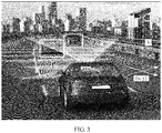
- the yaw angle yaw may be defined as an angle obtained by rotating the sensing apparatus around a y-axis
- the pitch angle pitch may be defined as an angle obtained by rotating the sensing apparatus around an x-axis
- the roll angle roll may be defined as an angle obtained by rotating the sensing apparatus around a z-axis.
- x and y indicate coordinates of the sensing apparatus projected on the ground of the road
- h indicates a vertical distance from the sensing apparatus to the ground of the road.
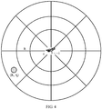
- the sensing distance of the target object and the sensing angle of the target object may be obtained in the following manner: As shown in FIG. 4 , using the sensing apparatus as a center, the sensing range of the sensing apparatus is divided into sector areas of different distances and different angles, so that a sensing coordinate system is created. The sensing apparatus determines the sensing distance R i of the target object and the sensing angle ⁇ j of the target object based on a sector area within which the target object falls in the sensing coordinate system.
- the roadside device and/or the vehicle device Before performing data fusion on the roadside sensing data and the vehicle sensing data to obtain the fusion result, the roadside device and/or the vehicle device need/needs to match the roadside sensing data with the vehicle sensing data to obtain a matching result, so that the roadside device and/or the vehicle device can perform data fusion on the roadside sensing data and the vehicle sensing data based on the matching result.
- the roadside sensing data expressed in the form of the roadside result set is: result r (roadside 1 , roadside 2 , ..., roadside M ), and that the vehicle sensing data expressed in the form of the vehicle result set is: result v (vehicle 1 , vehicle 2 , ..., vehicle N ), where M is the quantity of the target objects in the sensing range of the roadside sensing apparatus, N is the quantity of the target objects in the sensing range of the vehicle sensing apparatus, and M > N, where roadside 1 is a roadside result unit obtained by the roadside sensing apparatus by detecting a target object 1, roadside 2 is a roadside result unit obtained by the roadside sensing apparatus by detecting a target object 1, ..., and roadside M is a roadside result unit obtained by the roadside sensing apparatus by detecting a target object M; and vehiclei is a vehicle result unit obtained by the vehicle sensing
- roadside 1 and vehicle 1 are both result units obtained by detecting the target object 1, and have a matching relationship
- roadside 2 and vehicle 2 are both result units obtained by detecting the target object 2, and have a matching relationship
- ...; roadside N and vehicle N are both result units obtained by detecting the target object N, and have a matching relationship. Therefore, matching the roadside sensing data with the vehicle sensing data is finding out all matching relationships between roadside result units in the roadside sensing data and vehicle result units in the vehicle sensing data.
- the roadside device and/or the vehicle device may find out a matching relationship between a roadside result unit in the roadside sensing data and a vehicle result unit in the vehicle sensing data by using a deviation network.
- the roadside result unit and the vehicle result unit are used as an input of the deviation network.
- the deviation network outputs a matching result between the roadside result unit and the vehicle result unit.
- the matching result output by the deviation network is that the roadside result unit matches the vehicle result unit, it may be considered that the matching relationship exists between the roadside result unit and the vehicle result unit; or if the matching result output by the deviation network is that the roadside result unit does not match the vehicle result unit, it may be considered that the matching relationship does not exist between the roadside result unit and the vehicle result unit.
- roadside 1 and vehiclei are used as an input of the deviation network, and a matching result output by the deviation network is that roadsidei matches vehicle 1 , it may be determined that a matching relationship exists between roadside 1 and vehicle 1 ; or if roadside 1 and vehicle 2 are used as an input of the deviation network, and a matching result output by the deviation network is that roadsidei does not match vehicle 2 , it may be determined that a matching relationship does not exist between roadsidei and vehicle 2 .
- the deviation network Deviation may be expressed by using a back propagation (back propagation, BP) neural network shown in FIG. 5 , where
- the deviation network is described by using the BP neural network as an example.
- the deviation network may be a long short-term memory (Long Short-Term Memory, LSTM) network, a residual network (Residential Networking, ResNet), a recurrent neural network (Recurrent Neural Networks, RNN), or the like. This is not specifically limited herein.
- matching is implemented between roadside sensing data and vehicle sensing data in a single frame only, and confidence of a matching result is not high.
- matching between roadside sensing data and vehicle sensing data in two frames or even more frames may be considered, so that confidence of a matching result is improved.
- the roadside device and/or the vehicle device may further evaluate confidence of the matching result in a manner of interframe loopback and/or multiframe correlation to obtain an evaluation result, and adjust the deviation network based on the evaluation result.
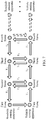
- the interframe loopback is mainly obtained through calculation based on a matching result obtained by cross-matching between roadside sensing data and vehicle sensing data in adjacent frames.
- the interframe loopback is mainly obtained based on an intraframe matching result and an interframe matching result of adjacent frames.
- the intraframe matching result is a matching result obtained by matching result units that are obtained by different sensing apparatuses by detecting a same target object in a same frame.
- the interframe matching result is a matching result obtained by matching result units that are obtained by a same sensing apparatus by detecting a same target object in adjacent frames.
- the first matching result is an intraframe matching result of an i th frame, that is, a matching result between a roadside result unit corresponding to the target object j detected by the roadside sensing apparatus in the i th frame and a vehicle result unit corresponding to the target object j detected by the vehicle sensing apparatus in the i th frame.
- the second matching result is an interframe matching result of the vehicle sensing apparatus, that is, a matching result between the vehicle result unit corresponding to the target object j detected by the vehicle sensing apparatus in the i th frame and a vehicle result unit corresponding to the target object j detected by the vehicle sensing apparatus in an (i+1) th frame.
- the third matching result is an intraframe matching result of the (i+1) th frame, that is, a matching result between the vehicle result unit corresponding to the target object j detected by the vehicle sensing apparatus in the (i+1) th frame and a roadside result unit corresponding to the target object j detected by the roadside sensing apparatus in the (i+1) th frame.
- the fourth matching result is an interframe matching result of the roadside sensing apparatus, that is, a matching result between the roadside result unit corresponding to the target object j detected by the roadside sensing apparatus in the (i+1) th frame and the roadside result unit corresponding to the target object j detected by the roadside sensing apparatus in the i th frame.
- the multiframe correlation is mainly obtained based on interframe loopback between a plurality of consecutive frames.
- the foregoing content of the specification focuses on a solution about how to implement data fusion on the roadside sensing data detected by the roadside sensing apparatus in the sensing range and the vehicle sensing data detected by the vehicle sensing apparatus in the sensing range.
- the following describes, from perspectives of a data fusion method and a related device, how the roadside sensing apparatus and/or the vehicle sensing apparatus use/uses the foregoing data fusion solution to extend the sensing range.
- FIG. 8 is a schematic flowchart of a first data fusion method according to an embodiment of this application.
- the data fusion method in this embodiment of this application specifically includes the following steps: S101.
- a vehicle device obtains vehicle sensing data, where the vehicle sensing data is obtained by a vehicle sensing apparatus by sensing a road environment in a sensing range by using a vehicle sensor.
- the vehicle sensing apparatus may be configured for the vehicle sensing device.
- the vehicle sensing apparatus includes at least one vehicle sensor, for example, a combined inertial navigation, a microwave radar, a millimeter-wave radar, and a camera, and can identify vehicle sensing data of a target object in the sensing range.
- the vehicle sensing data may include a position, a speed, a size, a color, and the like of the target object.
- the vehicle sensing apparatus may use any one of the vehicle sensors alone, or may use any plurality of the vehicle sensors simultaneously.
- a roadside device obtains roadside sensing data, where the roadside sensing data is obtained by a roadside sensing apparatus by sensing a road environment in a sensing range by using a roadside sensor.
- the roadside sensing apparatus may be configured for the roadside device.
- the roadside sensing apparatus includes at least one roadside sensor, for example, a microwave radar and a millimeter-wave radar, and can identify roadside sensing data of a target object in the sensing range.
- the roadside sensing data may include a position, a speed, a size, a color, and the like of the target object.
- the roadside sensing apparatus may use any one of the roadside sensors alone, or may use any plurality of the roadside sensors simultaneously.
- the roadside device sends the roadside sensing data to the vehicle device.
- the vehicle device receives the roadside sensing data sent by the roadside device.
- the vehicle device matches the roadside sensing data with the vehicle sensing data to obtain a matching result.
- the vehicle device may find out a matching relationship between a roadside result unit in the roadside sensing data and a vehicle result unit in the vehicle sensing data by using a deviation network.
- the roadside result unit and the vehicle result unit are used as an input of the deviation network.
- the deviation network outputs a matching result between the roadside result unit and the vehicle result unit.
- the vehicle device evaluates confidence of the matching result in a manner of interframe loopback and/or multiframe correlation, and adjusts the deviation network based on an evaluation result.
- the first matching result is an intraframe matching result of an i th frame, that is, a matching result between a roadside result unit corresponding to the target object j detected by the roadside sensing apparatus in the i th frame and a vehicle result unit corresponding to the target object j detected by the vehicle sensing apparatus in the i th frame.
- the second matching result is an interframe matching result of the vehicle sensing apparatus, that is, a matching result between the vehicle result unit corresponding to the target object j detected by the vehicle sensing apparatus in the i th frame and a vehicle result unit corresponding to the target object j detected by the vehicle sensing apparatus in an (i+1) th frame.
- the third matching result is an intraframe matching result of the (i+1) th frame, that is, a matching result between the vehicle result unit corresponding to the target object j detected by the vehicle sensing apparatus in the (i+1) th frame and a roadside result unit corresponding to the target object j detected by the roadside sensing apparatus in the (i+1) th frame.
- the fourth matching result is an interframe matching result of the roadside sensing apparatus, that is, a matching result between the roadside result unit corresponding to the target object j detected by the roadside sensing apparatus in the (i+1) th frame and the roadside result unit corresponding to the target object j detected by the roadside sensing apparatus in the i th frame.
- the multiframe correlation is mainly obtained based on interframe loopback between a plurality of consecutive frames.
- the vehicle device fuses the vehicle sensing data and the roadside sensing data by using a fusion formula, to obtain a first fusion result.
- the vehicle device may perform, by using the fusion formula, data fusion on the roadside sensing data detected by the roadside sensing apparatus in the sensing range and the vehicle sensing data detected by the vehicle sensing apparatus in the sensing range, to obtain the first fusion result.
- FIG. 9 is a schematic flowchart of a second data fusion method according to an embodiment of this application.
- the data fusion method in this embodiment of this application specifically includes the following steps: S201.
- a roadside device obtains roadside sensing data, where the roadside sensing data is obtained by a roadside sensing apparatus by sensing a road environment in a sensing range by using a roadside sensor.
- the roadside sensing apparatus may be configured for the roadside device.
- the roadside sensing apparatus includes at least one roadside sensor, for example, a microwave radar and a millimeter-wave radar, and can identify roadside sensing data of a target object in the sensing range.
- the roadside sensing data may include a position, a speed, a size, a color, and the like of the target object.
- the roadside sensing apparatus may use any one of the roadside sensors alone, or may use any plurality of the roadside sensors simultaneously.
- a vehicle device obtains vehicle sensing data, where the vehicle sensing data is obtained by a vehicle sensing apparatus by sensing a road environment in a sensing range by using a vehicle sensor.
- the vehicle sensing apparatus may be configured for the vehicle device.
- the vehicle sensing apparatus includes at least one vehicle sensor, for example, a combined inertial navigation, a microwave radar, a millimeter-wave radar, and a camera, and can identify vehicle sensing data of a target object in the sensing range.
- the vehicle sensing data may include a position, a speed, a size, a color, and the like of the target object.
- the vehicle sensing apparatus may use any one of the vehicle sensors alone, or may use any plurality of the vehicle sensors simultaneously.
- the vehicle device sends the vehicle sensing data to the roadside device.
- the roadside device receives the vehicle sensing data sent by the vehicle device.
- the roadside device matches the roadside sensing data with the vehicle sensing data to obtain a matching result.
- the roadside sensing apparatus may find out a matching relationship between a roadside result unit in the roadside sensing data and a vehicle result unit in the vehicle sensing data by using a deviation network.
- the roadside result unit and the vehicle result unit are used as an input of the deviation network.
- the deviation network outputs a matching result between the roadside result unit and the vehicle result unit.
- the roadside device evaluates confidence of the matching result in a manner of interframe loopback and/or multiframe correlation to obtain an evaluation result, and adjusts the deviation network based on the evaluation result.
- the first matching result is an intraframe matching result of an i th frame, that is, a matching result between a roadside result unit corresponding to the target object j detected by the roadside sensing apparatus in the i th frame and a vehicle result unit corresponding to the target object j detected by the vehicle sensing apparatus in the i th frame.
- the second matching result is an interframe matching result of the vehicle sensing apparatus, that is, a matching result between the vehicle result unit corresponding to the target object j detected by the vehicle sensing apparatus in the i th frame and a vehicle result unit corresponding to the target object j detected by the vehicle sensing apparatus in an (i+1) th frame.
- the third matching result is an intraframe matching result of the (i+1) th frame, that is, a matching result between the vehicle result unit corresponding to the target object j detected by the vehicle sensing apparatus in the (i+1) th frame and a roadside result unit corresponding to the target object j detected by the roadside sensing apparatus in the (i+1) th frame.
- the fourth matching result is an interframe matching result of the roadside sensing apparatus, that is, a matching result between the roadside result unit corresponding to the target object j detected by the roadside sensing apparatus in the (i+1) th frame and the roadside result unit corresponding to the target object j detected by the roadside sensing apparatus in the i th frame.
- the multiframe correlation is mainly obtained based on interframe loopback between a plurality of consecutive frames.
- the roadside device fuses the vehicle sensing data and the roadside sensing data by using a fusion formula, to obtain a first fusion result.
- the roadside sensing apparatus may perform, by using the fusion formula, data fusion on the roadside sensing data detected by the roadside sensing apparatus in the sensing range and the vehicle sensing data detected by the vehicle sensing apparatus in the sensing range, to obtain the first fusion result.
- FIG. 10 is a schematic flowchart of a third data fusion method according to an embodiment of this application.
- the data fusion method in this embodiment of this application specifically includes the following steps: S301.
- a roadside device obtains roadside sensing data, where the roadside sensing data is obtained by a roadside sensing apparatus by sensing a road environment in a sensing range by using a roadside sensor.
- the roadside sensing apparatus may be configured for the roadside device.
- the roadside sensing apparatus includes at least one roadside sensor, for example, a microwave radar and a millimeter-wave radar, and can identify roadside sensing data of a target object in the sensing range.
- the roadside sensing data may include a position, a speed, a size, a color, and the like of the target object.
- the roadside sensing apparatus may use any one of the roadside sensors alone, or may use any plurality of the roadside sensors simultaneously.
- At least one vehicle device obtains vehicle sensing data, where the vehicle sensing data is obtained by a vehicle sensing apparatus by sensing a road environment in a sensing range by using a vehicle sensor.
- the vehicle sensing apparatus may be configured for the vehicle device.
- the vehicle sensing apparatus includes at least one vehicle sensor, for example, a combined inertial navigation, a microwave radar, a millimeter-wave radar, and a camera, and can identify vehicle sensing data of a target object in the sensing range.
- the vehicle sensing data may include a position, a speed, a size, a color, and the like of the target object.
- the vehicle sensing apparatus may use any one of the vehicle sensors alone, or may use any plurality of the vehicle sensors simultaneously.
- the at least one vehicle device sends the vehicle sensing data to the roadside device.
- the roadside device receives the vehicle sensing data sent by the at least one vehicle device.
- the roadside device matches the roadside sensing data with the vehicle sensing data sent by the at least one vehicle device, to obtain a matching result.
- the roadside device may find out a matching relationship between a roadside result unit in the roadside sensing data and a vehicle result unit in the vehicle sensing data by using a deviation network.
- the roadside result unit and the vehicle result unit are used as an input of the deviation network.
- the deviation network outputs a matching result between the roadside result unit and the vehicle result unit.
- the roadside device evaluates confidence of the matching result in a manner of interframe loopback and/or multiframe correlation to obtain an evaluation result, and adjusts the deviation network based on the evaluation result.
- the first matching result is an intraframe matching result of an i th frame, that is, a matching result between a roadside result unit corresponding to the target object j detected by the roadside sensing apparatus in the i th frame and a vehicle result unit corresponding to the target object j detected by the vehicle sensing apparatus in the i th frame.
- the second matching result is an interframe matching result of the vehicle sensing apparatus, that is, a matching result between the vehicle result unit corresponding to the target object j detected by the vehicle sensing apparatus in the i th frame and a vehicle result unit corresponding to the target object j detected by the vehicle sensing apparatus in an (i+1) th frame.
- the third matching result is an intraframe matching result of the (i+1) th frame, that is, a matching result between the vehicle result unit corresponding to the target object j detected by the vehicle sensing apparatus in the (i+1) th frame and a roadside result unit corresponding to the target object j detected by the roadside sensing apparatus in the (i+1) th frame.
- the fourth matching result is an interframe matching result of the roadside sensing apparatus, that is, a matching result between the roadside result unit corresponding to the target object j detected by the roadside sensing apparatus in the (i+1) th frame and the roadside result unit corresponding to the target object j detected by the roadside sensing apparatus in the i th frame.
- the multiframe correlation is mainly obtained based on interframe loopback between a plurality of consecutive frames.
- the roadside device fuses the vehicle sensing data sent by the at least one vehicle device and the roadside sensing data by using a fusion formula, to obtain a first fusion result.
- the roadside device may perform, by using the fusion formula, data fusion on the roadside sensing data detected by the roadside sensing apparatus in the sensing range and the vehicle sensing data detected by the vehicle sensing apparatus in the sensing range, to obtain the first fusion result.
- the first fusion result may be obtained by the roadside sensing apparatus by fusing vehicle sensing data sent by one or more vehicle sensing apparatuses and the roadside sensing data of the roadside sensing apparatus by using the fusion formula. This is not specifically limited.
- the roadside device sends the first fusion result to a target vehicle device.
- the target vehicle device receives the first fusion result sent by the roadside device.
- the target vehicle device belongs to the at least one vehicle device.
- the target vehicle device fuses the first fusion result and vehicle sensing data of the target vehicle device to obtain a second fusion result.
- the target vehicle device may perform data fusion on the first fusion result and the vehicle sensing data of the target vehicle device by using a fusion formula, to obtain the second fusion result.
- the process of fusing the first fusion result and the vehicle sensing data is similar to the process of fusing the roadside sensing data and the vehicle sensing data, and is not described again herein.
- the roadside device may fuse the vehicle sensing data sent by the plurality of vehicle sensing apparatuses and the roadside sensing data of the roadside device to obtain the first fusion result with a wider sensing range (the sensing range herein is a result of overlapping between the sensing range of the roadside sensing apparatus and sensing ranges of the plurality of vehicle sensing apparatuses), and then send the first fusion result to the target vehicle device, so that the target vehicle device fuses the first fusion result and the vehicle sensing data to extend the sensing range of the vehicle sensing apparatus.
- the sensing range herein is a result of overlapping between the sensing range of the roadside sensing apparatus and sensing ranges of the plurality of vehicle sensing apparatuses
- an embodiment of this application provides a fusion apparatus, where the device may be applied to a vehicle device, or may be applied to a roadside device.
- the fusion apparatus may be a chip, a programmable component, a circuit component, a device (that is, the fusion apparatus is a vehicle device or a roadside device), a system, or the like, and is not specifically limited herein.
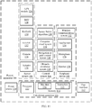
- the fusion apparatus 100 includes a sensor system 104, a control system 106, a peripheral device 108, a power source 110, and a calculation apparatus 112.
- the calculation apparatus 112 may include a processor 113 and a memory 114.
- the calculation apparatus 112 may be a controller of the fusion apparatus 100 or a part of a controller.
- the memory 114 may include an instruction 115 that may be run by the processor 113, and may further store map data 116.
- Components of the fusion apparatus 100 may be configured to work in a manner of interconnection with each other and/or interconnection with other components coupled to various systems.
- the power source 110 may supply power for all components of the fusion apparatus 100.
- the calculation apparatus 111 may be configured to receive data from the sensor system 104, the control system 106, and the peripheral device 108, and control them.
- the fusion apparatus 100 may include more, fewer, or different systems, and each system may include more, fewer, or different components.
- the shown systems and components may be combined or split in any manner.
- the sensor system 104 may include several sensors configured to sense a road environment in a sensing range of the fusion apparatus 100.
- the sensors of the sensor system include a GPS 126, an IMU (Inertial Measurement Unit, inertial measurement unit) 128, a radio detection and radar ranging (RADAR) unit 130, a laser ranging (LIDAR) unit 132, a camera 134, and an actuator 136 configured to change a position and/or an orientation of a sensor.
- IMU Inertial Measurement Unit, inertial measurement unit
- RADAR radio detection and radar ranging
- LIDAR laser ranging
- the GPS module 126 may be any sensor configured to estimate a geographical position of a vehicle. Therefore, the GPS module 126 may include a transceiver, and estimate a position of the fusion apparatus 100 relative to the earth based on satellite positioning data. In an example, by using the GPS module 126 and referring to the map data 116, the calculation apparatus 111 may be configured to estimate a position of the fusion apparatus 100 at a lane edge on a road on which the vehicle device can drive. Alternatively, the GPS module 126 may be in another form.
- the IMU 128 may be configured to sense position and orientation changes of the vehicle based on inertial, acceleration, and any combination thereof.
- a combination of sensors may include an accelerometer and a gyro. Other combinations of sensors are also possible.
- the RADAR unit 130 may be considered as an object detection system.
- the RADAR unit 130 is configured to use a radio wave to detect a feature of a target object, for example, a distance, a height, a direction, or a speed of an object.
- the RADAR unit 130 may be configured to transmit a radio wave or a microwave pulse.
- the radio wave or the microwave pulse may be reflected by any object in a path of the wave.
- the object may return a part of energy of the wave to a receiver (for example, a dish antenna or an antenna), and the receiver may also be a part of the RADAR unit 130.
- the RADAR unit 130 may be further configured to perform digital signal processing on a received signal (reflected from an object), and may be configured to identify a target object.
- LIDAR light detection and ranging
- the LIDAR unit 132 includes a sensor, where the sensor uses light to sense or detect a target object in the road environment in the sensing range of the fusion apparatus 100.
- the LIDAR is an optical remote sensing technology that may use light to illuminate a target to measure a distance to a target object or other attributes of the target object.
- the LIDAR unit 132 may include a laser source and/or a laser scanner configured to transmit a laser pulse, and a detector configured to receive reflection of the laser pulse.
- the LIDAR unit 132 may include a laser rangefinder based on reflection by a rotation mirror, and perform laser scanning around a digital scene in one dimension or two dimensions, to collect distance measurement values from a specified angle at specified intervals.
- the LIDAR unit 132 may include components such as a light (for example, laser) source, a scanner, an optical system, an optical detector, and a receiver or an electronic component, and a position and navigation system.
- the LIDAR unit 132 may be configured to use ultraviolet (UV), visible light, or infrared light for object imaging, and may be applied to a wide range of target objects, including non-metallic objects.
- a narrow laser beam may be used to draw a map about physical features of an object with a high resolution.
- wavelengths in a range from about 10 microns (infrared) to about 250 nanometers (UV) may be used.
- Light is generally reflected after backscattering.
- Different types of scattering for example, Rayleigh scattering, Mie scattering, Raman scattering, and fluorescent, are used in different LIDAR applications.
- the LIDAR may be therefore referred to as a Rayleigh laser RADAR, a Mie LIDAR, a Raman LIDAR, and a sodium/Fe/potassium fluorescent LIDAR.
- An appropriate combination of wavelengths may allow, for example, remote map drawing for an object by searching for a wavelength-dependent change of strength of a reflected signal.
- Three-dimensional (3D) imaging may be implemented by using a scanning LIDAR system and a non-scanning LIDAR system.
- a 3D gated viewing laser RADAR (3D gated viewing laser radar)
- a pulsed laser and a fast gated camera are applied in the 3D gated viewing laser RADAR.
- An imaging LIDAR may also be implemented by using a high-speed detector array and a modulation sensitive detector array built on a single chip generally by using CMOS (Complementary Metal Oxide Semiconductor, complementary metal oxide semiconductor) and CCD (Charge Coupled Device, hybrid complementary metal oxide semiconducto/charge coupled device) fabrication techniques.
- CMOS Complementary Metal Oxide Semiconductor, complementary metal oxide semiconductor
- CCD Charge Coupled Device, hybrid complementary metal oxide semiconducto/charge coupled device
- each pixel may be locally processed through high-speed demodulation or gating, so that the array can be processed to represent an image from a camera.
- This technology can be used to simultaneously obtain thousands of pixels to create a 3D point cloud representing an object or a scene detected by the LIDAR unit 132.
- the point cloud may include a group of vertices in a 3D coordinate system.
- the vertices may be defined, for example, by X, Y, and Z coordinates, and may represent an outer surface of a target object.
- the LIDAR unit 132 may be configured to create a point cloud by measuring a large quantity of points on the surface of the target object, and may use the point cloud as a data file for outputting. As a result of a 3D scanning process performed on the object by using the LIDAR unit 132, the point cloud may be used to identify and visualize the target object.
- the point cloud may be directly rendered to visualize the target object.
- the point cloud may be converted into a polygonal or triangular grid model in a process that may be referred to as surface reconstruction.
- Example technologies for converting the point cloud into a 3D surface may include: Delaunay triangulation, alpha shape, and rotating sphere.
- the technologies include constructing a triangular network on the existing vertices of the point cloud.
- Other example technologies may include converting the point cloud into a volume distance field, and reconstructing, by using a marching cubes algorithm, an implicit surface defined in this manner.
- the camera 134 may be any camera (for example, a static camera or a video camera) configured to obtain an image of the road environment in which the vehicle is located. Therefore, the camera may be configured to detect visible light, or may be configured to detect light from other parts of spectrums (for example, infrared light or ultraviolet). Other types of cameras are also possible.
- the camera 134 may be a two-dimensional detector, or may have a three-dimensional space range.
- the camera 134 may be, for example, a distance detector, and the camera 134 is configured to generate a two-dimensional image indicating distances from the camera 134 to several points in the environment. Therefore, the camera 134 may use one or more distance detection technologies.
- the camera 134 may be configured to use a structured light technology.
- the fusion apparatus 100 uses a predetermined light pattern, for example, a grid or chessboard grid pattern, to illuminate an object in the environment, and uses the camera 134 to detect reflection of the predetermined light pattern from the object. Based on distortion in the reflected light pattern, the fusion apparatus 100 may be configured to detect a distance to a point on the object.
- the predetermined light pattern may include infrared light or light of other wavelengths.
- the actuator 136 may be configured to change a position and/or an orientation of a sensor.
- the sensor system 104 may additionally or alternatively include a component other than the shown components.
- the control system 106 may be configured to control operations of the fusion apparatus 100 and components of the fusion apparatus 100. Therefore, the control system 106 may include a sensor fusion algorithm 144, a computer visual system 146, a navigation or path control (pathing) system 148, and an obstacle avoidance system 150.
- the sensor fusion algorithm 144 may include, for example, an algorithm (or a computer program product storing an algorithm) that the calculation apparatus 111 may run.
- the sensor fusion algorithm 144 may be configured to accept data from the sensor 104 as an input.
- the data may include, for example, data of information detected by a sensor of the sensor system 104.
- the sensor fusion algorithm 144 may include, for example, a Kalman filter, a Bayesian network, or another algorithm.
- the sensor fusion algorithm 144 may be further configured to provide various evaluations based on data from the sensor system 104, including, for example, an evaluation on an individual object and/or feature in the environment in which the vehicle is located, an evaluation on a specific situation, and/or an evaluation on possible impact based on a specific situation. Other evaluations are also possible.
- the computer visual system 146 may be any system configured to process and analyze an image captured by the camera 134, to identify an object and/or a feature in the environment in which the fusion apparatus 100 is located, where the object and/or feature include/includes, for example, lane information, a traffic signal, and an obstacle. Therefore, the computer visual system 146 may use an object identification algorithm, a structure from motion (Structure from Motion, SFM) algorithm, video tracking, or another computer visual technology. In some examples, the computer visual system 146 may be additionally configured to draw an environment map, follow an object, estimate a speed of the object, and the like.
- SFM Structure from Motion
- the navigation and path control system 148 may be any system configured to determine a driving path of the vehicle.
- the navigation and path control system 148 may be additionally configured to dynamically update the driving path when the vehicle is in an operation.
- the navigation and path control system 148 may be configured to determine the driving path for the vehicle with reference to data from the sensor fusion algorithm 144, the GPS module 126, and one or more predetermined maps.
- the obstacle avoidance system 150 may be any system configured to identify, evaluate, and avoid, or overtake in another manner, an obstacle in the environment in which the vehicle is located.
- the control system 106 may additionally or alternatively include a component other than the shown components.
- the peripheral device 108 may be configured to allow the fusion apparatus 100 to interact with an external sensor, another vehicle, and/or a user. Therefore, the peripheral device 108 may include, for example, a wireless communications system 152, a touchscreen 154, a microphone 156, and/or a speaker 158.
- the wireless communications system 152 may be any system configured to couple to one or more other vehicles, a sensor, or another entity directly or by using a communications network in a wireless manner. Therefore, the wireless communications system 152 may include an antenna and a chip set configured to communicate with the another vehicle, the sensor, or the another entity directly or by using an air interface.
- the chip set or the entire wireless communications system 152 may be configured to communicate based on one or more other types of wireless communication (for example, protocols), where the wireless communication is, for example, Bluetooth, a communication protocol described in IEEE 802.11 (including any IEEE 802.11 revision), a cellular technology (for example, GSM, CDMA, UMTS (Universal Mobile Telecommunications System, universal mobile telecommunications system), EV-DO, WiMAX, or LTE (Long Term Evolution, long term evolution), ZigBee, DSRC (Dedicated Short Range Communications, dedicated short range communications), RFID (Radio Frequency Identification, radio frequency identification), and the like.
- the wireless communications system 152 may also be in another form.
- the touchscreen 154 may be used by the user to input a command to the fusion apparatus 100. Therefore, the touchscreen 154 may be configured to sense at least one of a position and motion of a finger of the user through capacitive sensing, resistive sensing, a surface acoustic wave process, or the like.
- the touchscreen 154 can sense the motion of the finger in a direction that is parallel to a surface of the touchscreen or is in a same plane as a surface of the touchscreen, in a direction vertical to a surface of the touchscreen, or in both directions, and can further sense a level of pressure applied to the surface of the touchscreen.
- the touchscreen 154 may include one or more translucent or transparent insulating layers and one or more translucent or transparent conducting layers.
- the touchscreen 154 may also be in another form.
- the microphone 156 may be configured to receive an audio (for example, a voice command or another audio input) from the user of the fusion apparatus 100.
- the speaker 158 may be configured to output an audio to the user of the fusion apparatus 100.
- the peripheral device 108 may additionally or alternatively include a component other than the shown components.
- the power source 110 may be configured to supply power for some or all of components of the fusion apparatus 100. Therefore, the power source 110 may include, for example, a rechargeable lithium-ion or lead-acid battery. In some examples, one or more battery groups may be configured to supply power. Other power materials and configurations are also possible. In some examples, the power source 110 and an energy source 120 may be implemented together, as in an electric vehicle.
- the processor 113 included in the calculation apparatus 111 may include one or more general purpose processors and/or one or more dedicated processors (for example, an image processor or a digital signal processor). If the processor 113 includes more than one processor, the processors may work independently or work in combination.
- the calculation apparatus 111 may implement a function of controlling the vehicle 100 based on an input received by using a user interface 112.
- the memory 114 may further include one or more volatile storage components and/or one or more non-volatile storage components, such as an optical, magnetic, and/or organic storage apparatus, and the memory 114 may be integrated with the processor 113 completely or partially.
- the memory 114 may include an instruction 115 (for example, program logic) that is run by the processor 113, to run various vehicle functions, including any one of the functions or methods described in the specification.
- the components of the fusion apparatus 100 may be configured to work in a manner of interconnection with other components in respective systems and/or interconnection with other external components. Therefore, the components and systems of the fusion apparatus 100 may be communicatively interconnected by using a system bus, a network, and/or another connection mechanism.
- the processor 113 of the fusion apparatus 100 executes the following instruction:
- the processor 113 of the fusion apparatus 100 executes the following instruction:
- the confidence factor is determined based on a sensing apparatus parameter, a sensing distance of the target object, and a sensing angle of the target object together.
- the vehicle result set includes at least one vehicle result unit, a one-to-one correspondence exists between the at least one vehicle result unit and at least one target object, and each vehicle result unit in the at least one vehicle result unit is used to describe a feature of a corresponding target object from a multidimensional angle.
- one vehicle result unit in the at least one vehicle result unit is expressed as vehiclej (p vj , v vj , s vj , c vj ), where p vj indicates a position of the target object j detected by the vehicle sensing apparatus, v vj indicates a speed of the target object j detected by the vehicle sensing apparatus, s vj indicates a size of the target object j detected by the vehicle sensing apparatus, c vj indicates a color of the target object j detected by the vehicle sensing apparatus, N is the quantity of target objects in the sensing range of the vehicle sensing apparatus, j is a natural number, and 0 ⁇ j ⁇ N.
- the roadside result set includes at least one roadside result unit, a one-to-one correspondence exists between the at least one roadside result unit and at least one target object, and each roadside result unit in the at least one roadside result unit is used to describe a feature of a corresponding target object from a multidimensional angle.
- one roadside result unit in the at least one roadside result unit is expressed as roadsidei (p vi , v vi , s vi , c vi ), where p vi indicates a position of the target object i detected by the roadside sensing apparatus, v vi indicates a speed of the target object i detected by the roadside sensing apparatus, s vi indicates a size of the target object i detected by the roadside sensing apparatus, c vi indicates a color of the target object i detected by the roadside sensing apparatus, M is the quantity of target objects in the sensing range of the roadside sensing apparatus, i is a natural number, and 0 ⁇ i ⁇ M.
- the method before the fusing the vehicle sensing data and the roadside sensing data by using a fusion formula, to obtain a first fusion result, the method includes: matching the roadside sensing data with the vehicle sensing data to obtain a matching result; and fusing the vehicle sensing data and the roadside sensing data based on the matching result, to obtain the first fusion result.
- a matching relationship between a roadside result unit in the roadside result set and a vehicle result unit in the vehicle result set is found out by using a deviation network.
- the method includes: evaluating confidence of the matching result in a manner of interframe loopback and/or multiframe correlation to obtain an evaluation result; and adjusting the deviation network based on the evaluation result.
- T multiframe is the multiframe correlation
- T loopback2 is interframe loopback between a first frame and a second frame
- T loopback23 is interframe loopback between the second frame and a third frame
- T loopback34 is interframe loopback between the third frame and a fourth frame, ....
- the fusion apparatus 200 when a fusion apparatus is a roadside device, the fusion apparatus 200 includes components such as an RF (Radio Frequency, radio frequency) circuit 210, a memory 220, another input device 230, a display screen 240, a sensor system 250, an I/O subsystem 270, a processor 280, and a power source 290.
- RF Radio Frequency, radio frequency
- a roadside sensing apparatus is not limited to a structure of the roadside sensing apparatus shown in FIG. 12 .
- the roadside sensing apparatus may include more or fewer parts than that shown in the figure, or some parts are combined, or some parts are split, or an arrangement of parts is different.
- the display screen 240 may be configured to display a user interface (UI, User Interface).
- UI User Interface
- the RF circuit 210 may be configured to send or receive data.
- the RF circuit includes but is not limited to an antenna, at least one amplifier, a transceiver, a coupler, an LNA (Low Noise Amplifier, low noise amplifier), a duplexer, and the like.
- the RF circuit 210 may further communicate with a network and other devices through wireless communication.
- the wireless communication may use any communication standard or protocol, including but not limited to the GSM (Global System of Mobile communications, global system for mobile communications), GPRS (General Packet Radio Service, general packet radio service), CDMA (Code Division Multiple Access, code division multiple access), WCDMA (Wideband Code Division Multiple Access, wideband code division multiple access), LTE (Long Term Evolution, long term evolution), e-mail, SMS (Short Messaging Service, short message service), and the like.
- GSM Global System of Mobile communications, global system for mobile communications
- GPRS General Packet Radio Service, general packet radio service
- CDMA Code Division Multiple Access, code division multiple access
- WCDMA Wideband Code Division Multiple Access, wideband code division multiple access
- LTE Long Term Evolution, long term evolution
- e-mail Short Messaging Service, short message service
- the memory 220 may include a high-speed random access memory, and may further include a non-volatile memory, for example, at least one magnetic disk storage device, a flash memory, or another volatile solid-state storage device.
- the memory 220 may include an instruction 222 that may be run by the processor 280, and may further store map data 224.
- the another input device 230 may be configured to receive input digit or character information, and generate a key signal input related to a user setting and function control of the fusion apparatus 200.
- the another input device 230 may include but is not limited to one or more of a physical keyboard, a function key (such as a volume control key and a power on/off key), a trackball, a mouse, a joystick, an optical mouse (the optical mouse is a touch-sensitive surface that does not display a visual output, or is an extension of a touch-sensitive surface formed by a touchscreen), and the like.
- the another input device 230 is connected to another input device controller 271 of the I/O subsystem 270, and is controlled by the another input device controller 271 to perform signal interaction with the processor 280.
- the display screen 240 may include a display panel 241 and a touch panel 242.
- the display panel 241 may be configured in a form of an LCD (Liquid Crystal Display, liquid crystal display), an OLED (Organic Light-Emitting Diode, organic light-emitting diode), or the like.
- the touch panel 242 also referred to as a touchscreen, a touch-sensitive screen, or the like, may capture a touch or non-touch operation of a user on or near the touch panel (for example, the operation is an operation performed by the user by using any appropriate object or accessory such as a finger or a stylus on the touch panel 242 or near the touch panel 242, or may include a motion sensing operation; and an operation type of the operation includes a single-point control operation, or a multipoint control operation, or the like), and drive a corresponding connection apparatus based on a preset program.
- the operation is an operation performed by the user by using any appropriate object or accessory such as a finger or a stylus on the touch panel 242 or near the touch panel 242, or may include a motion sensing operation; and an operation type of the operation includes a single-point control operation, or a multipoint control operation, or the like
- drive a corresponding connection apparatus based on a preset program.
- the sensor system 250 may include several sensors configured to sense a road environment in a sensing range of the fusion apparatus 200. As shown in the figure, the sensors of the sensor system include a GPS 251, a radio detection and radar ranging (RADAR) unit 255, a laser ranging (LIDAR) unit 257, a camera 258, and an actuator 259 configured to change a position and/or an orientation of a sensor.
- the sensor system 250 is connected to a sensor controller 272 of the I/O subsystem 270, and is controlled by the sensor controller 272 to perform interaction with the processor 280.
- the GPS module 251 may be any sensor configured to estimate a geographical position of a vehicle. Therefore, the GPS module 251 may include a transceiver, and estimate a position of the fusion apparatus 200 relative to the earth based on satellite positioning data. In an example, the fusion apparatus 200 may be configured to estimate a position of the fusion apparatus 200 on a road by using the GPS module 251 and referring to the map data 224. Alternatively, the GPS module 126 may be in another form.
- the RADAR unit 255 may be considered as an object detection system.
- the RADAR unit 255 is configured to use a radio wave to detect a feature of a target object, for example, a distance, a height, a direction, or a speed of an object.
- the RADAR unit 255 may be configured to transmit a radio wave or a microwave pulse.
- the radio wave or the microwave pulse may be reflected by any object in a path of the wave.
- the object may return a part of energy of the wave to a receiver (for example, a dish antenna or an antenna), and the receiver may also be a part of the RADAR unit 255.
- the RADAR unit 255 may be further configured to perform digital signal processing on a received signal (reflected from an object), and may be configured to identify a target object.
- LIDAR light detection and ranging
- the LIDAR unit 257 includes a sensor, where the sensor uses light to sense or detect a target object in the road environment in the sensing range of the fusion apparatus 200.
- the LIDAR is an optical remote sensing technology that may use light to illuminate a target to measure a distance to a target object or other attributes of the target object.
- the LIDAR unit 257 may include a laser source and/or a laser scanner configured to transmit a laser pulse, and a detector configured to receive reflection of the laser pulse.
- the LIDAR unit 257 may include a laser rangefinder based on reflection by a rotation mirror, and perform laser scanning around a digital scene in one dimension or two dimensions, to collect distance measurement values from a specified angle at specified intervals.
- the LIDAR unit 257 may include components such as a light (for example, laser) source, a scanner, an optical system, an optical detector, and a receiver or an electronic component, and a position and navigation system.
- the LIDAR unit 257 may be configured to use ultraviolet (UV), visible light, or infrared light for object imaging, and may be applied to a wide range of target objects, including non-metallic objects.
- a narrow laser beam may be used to draw a map about physical features of an object with a high resolution.
- wavelengths in a range from about 10 microns (infrared) to about 250 nanometers (UV) may be used.
- Light is generally reflected after backscattering.
- Different types of scattering for example, Rayleigh scattering, Mie scattering, Raman scattering, and fluorescent, are used in different LIDAR applications.
- the LIDAR may be therefore referred to as a Rayleigh laser RADAR, a Mie LIDAR, a Raman LIDAR, and a sodium/Fe/potassium fluorescent LIDAR.
- An appropriate combination of wavelengths may allow, for example, remote map drawing for an object by searching for a wavelength-dependent change of strength of a reflected signal.
- Three-dimensional (3D) imaging may be implemented by using a scanning LIDAR system and a non-scanning LIDAR system.
- a 3D gated viewing laser RADAR (3D gated viewing laser radar)
- a pulsed laser and a fast gated camera are applied in the 3D gated viewing laser RADAR.
- An imaging LIDAR may also be implemented by using a high-speed detector array and a modulation sensitive detector array built on a single chip generally by using CMOS (Complementary Metal Oxide Semiconductor, complementary metal oxide semiconductor) and CCD (Charge Coupled Device, hybrid complementary metal oxide semiconducto/charge coupled device) fabrication techniques.
- CMOS Complementary Metal Oxide Semiconductor, complementary metal oxide semiconductor
- CCD Charge Coupled Device, hybrid complementary metal oxide semiconducto/charge coupled device
- each pixel may be locally processed through high-speed demodulation or gating, so that the array can be processed to represent an image from a camera.
- This technology can be used to simultaneously obtain thousands of pixels to create a 3D point cloud representing an object or a scene detected by the LIDAR unit 257.
- the point cloud may include a group of vertices in a 3D coordinate system.
- the vertices may be defined, for example, by X, Y, and Z coordinates, and may represent an outer surface of a target object.
- the LIDAR unit 257 may be configured to create a point cloud by measuring a large quantity of points on the surface of the target object, and may use the point cloud as a data file for outputting. As a result of a 3D scanning process performed on the object by using the LIDAR unit 257, the point cloud may be used to identify and visualize the target object.
- the point cloud may be directly rendered to visualize the target object.
- the point cloud may be converted into a polygonal or triangular grid model in a process that may be referred to as surface reconstruction.
- Example technologies for converting the point cloud into a 3D surface may include: Delaunay triangulation, alpha shape, and rotating sphere.
- the technologies include constructing a triangular network on the existing vertices of the point cloud.
- Other example technologies may include converting the point cloud into a volume distance field, and reconstructing, by using a marching cubes algorithm, an implicit surface defined in this manner.
- the camera 258 may be any camera (for example, a static camera or a video camera) configured to obtain an image of a road environment in which the vehicle is located. Therefore, the camera may be configured to detect visible light, or may be configured to detect light from other parts of spectrums (for example, infrared light or ultraviolet). Other types of cameras are also possible.
- the camera 258 may be a two-dimensional detector, or may have a three-dimensional space range.
- the camera 258 may be, for example, a distance detector, and the camera 258 is configured to generate a two-dimensional image indicating distances from the camera 258 to several points in the environment. Therefore, the camera 258 may use one or more distance detection technologies.
- the camera 258 may be configured to use a structured light technology.
- the fusion apparatus 200 uses a predetermined light pattern, for example, a grid or chessboard grid pattern, to illuminate an object in the environment, and uses the camera 258 to detect reflection of the predetermined light pattern from the object. Based on distortion in the reflected light pattern, the roadside sensing apparatus 258 may be configured to detect a distance to a point on the object.
- the predetermined light pattern may include infrared light or light of other wavelengths.
- the I/O subsystem 270 is configured to control external input/output devices, and may include the another input device controller 271 and the sensor controller 272.
- one or more other input control device controllers 271 receive a signal from the another input device 230 and/or send a signal to the another input device 230.
- the another input device 230 may include a physical button (push button, rocker arm button, or the like), a dial, a slider switch, a joystick, a scroll wheel, or an optical mouse (the optical mouse is a touch-sensitive surface that does not display a visual output, or is an extension of a touch-sensitive surface formed by a touchscreen).
- the other input control device controller 271 may be connected to any one or more of the foregoing devices.
- the sensor controller 272 may receive a signal from one or more sensors 250 and/or send a signal to one or more sensors 250.
- the processor 280 is a control center of the fusion apparatus 200.
- the processor 280 is connected to all parts of the entire fusion apparatus 200 by using various interfaces and lines, and executes various functions and data processing of the fusion apparatus 200 by running or executing a software program and/or module stored in the memory 220 and invoking data stored in the memory 220, thereby performing overall monitoring on the fusion apparatus 200.
- the processor 280 may include one or more processing units.
- the processor 280 may integrate two modem processors, where the modem processors mainly process wireless communication. It may be understood that, alternatively, the modem processors may not be integrated in the processor 280.
- the fusion apparatus 200 further includes the power source 290 (such as a battery) for supplying power to the components.
- the power source may be logically connected to the processor 280 by using a power management system, thereby implementing functions such as managing charging, discharging, and power consumption by using the power management system.
- the processor 280 of the fusion apparatus 200 executes the following instruction:
- the confidence factor is determined based on a sensing apparatus parameter, a sensing distance of the target object, and a sensing angle of the target object together.
- the vehicle result set includes at least one vehicle result unit, a one-to-one correspondence exists between the at least one vehicle result unit and at least one target object, and each vehicle result unit in the at least one vehicle result unit is used to describe a feature of a corresponding target object from a multidimensional angle.
- one vehicle result unit in the at least one vehicle result unit is expressed as vehiclej (p vj , v vj , s vj , c vj ), where p vj indicates a position of the target object j detected by the vehicle sensing apparatus, v vj indicates a speed of the target object j detected by the vehicle sensing apparatus, s vj indicates a size of the target object j detected by the vehicle sensing apparatus, c vj indicates a color of the target object j detected by the vehicle sensing apparatus, N is the quantity of target objects in the sensing range of the vehicle sensing apparatus, j is a natural number, and 0 ⁇ j ⁇ N.
- the roadside result set includes at least one roadside result unit, a one-to-one correspondence exists between the at least one roadside result unit and at least one target object, and each roadside result unit in the at least one roadside result unit is used to describe a feature of a corresponding target object from a multidimensional angle.
- one roadside result unit in the at least one roadside result unit is expressed as roadside i (p vi , v vi , s vi , c vi ), where p vi indicates a position of the target object i detected by the roadside sensing apparatus, v vi indicates a speed of the target object i detected by the roadside sensing apparatus, s vi indicates a size of the target object i detected by the roadside sensing apparatus, c vi indicates a color of the target object i detected by the roadside sensing apparatus, M is the quantity of target objects in the sensing range of the roadside sensing apparatus, i is a natural number, and 0 ⁇ i ⁇ M.
- the method before the fusing the vehicle sensing data and the roadside sensing data by using a fusion formula, to obtain a fusion result, the method includes: matching the roadside sensing data with the vehicle sensing data to obtain a matching result; and fusing the vehicle sensing data and the roadside sensing data based on the matching result, to obtain the first fusion result.
- a matching relationship between a roadside result unit in the roadside result set and a vehicle result unit in the vehicle result set is found out by using a deviation network.
- the method includes: evaluating confidence of the matching result in a manner of interframe loopback and/or multiframe correlation to obtain an evaluation result; and adjusting the deviation network based on the evaluation result.
- T multiframe is the multiframe correlation
- T loopback2 is interframe loopback between a first frame and a second frame
- T loopback23 is interframe loopback between the second frame and a third frame
- T loopback34 is interframe loopback between the third frame and a fourth frame, ....
- FIG. 13 is a schematic structural diagram of a fusion apparatus according to an embodiment of the present invention.
- the fusion apparatus 300 may include a first obtaining module 301, a second obtaining module 302, and a fusion module 303.
- the first obtaining module 301 is configured to obtain vehicle sensing data, where the vehicle sensing data is obtained by a vehicle sensing apparatus by sensing a road environment in a sensing range.
- the second obtaining module 302 is configured to obtain roadside sensing data, where the roadside sensing data is obtained by a roadside sensing apparatus by sensing a road environment in a sensing range.
- the fusion module 303 is configured to fuse the vehicle sensing data and the roadside sensing data by using a fusion formula, to obtain a first fusion result.
- FIG. 14 is a schematic structural diagram of a fusion apparatus according to an embodiment of the present invention.
- the fusion apparatus 400 in this embodiment includes a sending module 401, a receiving module 402, and a fusion module 403.
- the sending module 401 is configured to send vehicle sensing data to a roadside device, where the vehicle sensing data is obtained by a vehicle sensing apparatus by sensing a road environment in a sensing range.
- the receiving module 402 is configured to receive a first fusion result sent by the roadside device, where the first fusion result is obtained by the roadside device by fusing vehicle sensing data of at least one vehicle device and roadside sensing data by using a fusion formula, and the roadside sensing data is obtained by a roadside sensing apparatus by sensing a road environment in a sensing range.
- the fusion module 403 is configured to fuse the vehicle sensing data of the at least one vehicle device and the first fusion result to obtain a second fusion result.
- the roadside sensing data obtained by the roadside sensing apparatus by sensing and the vehicle sensing data obtained by the vehicle sensing apparatus by sensing are fused to implement overlapping between the sensing range of the roadside sensing apparatus and the sensing range of the vehicle sensing apparatus, so that the sensing range is effectively extended.
- the disclosed system, terminal, and method may be implemented in other manners.
- the described apparatus embodiment is merely an example.
- the unit division is merely logical function division and may be other division in actual implementation.
- a plurality of units or components may be combined or integrated into another system, or some features may be ignored or may not be performed.
- the displayed or discussed mutual couplings or direct couplings or communication connections may be implemented through some interfaces, indirect couplings or communication connections between the apparatuses or units, or electrical connections, mechanical connections, or connections in other forms.
- the units described as separate parts may or may not be physically separate, and parts displayed as units may or may not be physical units, may be located in one position, or may be distributed on a plurality of network units. Some or all of the units may be selected according to actual requirements to achieve the objectives of the solutions of the embodiments of the present invention.
- functional units in the embodiments of the present invention may be integrated into one processing unit, or each of the units may exist alone physically, or two or more units are integrated into one unit.
- the integrated unit may be implemented in a form of hardware, or may be implemented in a form of a software functional unit.
- the integrated unit When the integrated unit is implemented in the form of a software functional unit and sold or used as an independent product, the integrated unit may be stored in a computer-readable storage medium. Based on such an understanding, the technical solutions of the present invention essentially, or the part contributing to the prior art, or all or some of the technical solutions may be implemented in the form of a software product.
- the computer software product is stored in a storage medium and includes several instructions for instructing a computer device (which may be a personal computer, a server, a network device, or the like) to perform all or some of the steps of the methods described in the embodiments of the present invention.
- the foregoing storage medium includes any medium that can store program code, such as a USB flash drive, a removable hard disk, a read-only memory (ROM, Read-Only Memory), a random access memory (RAM, Random Access Memory), a magnetic disk, or an optical disc.
- program code such as a USB flash drive, a removable hard disk, a read-only memory (ROM, Read-Only Memory), a random access memory (RAM, Random Access Memory), a magnetic disk, or an optical disc.
Landscapes
- Engineering & Computer Science (AREA)
- Physics & Mathematics (AREA)
- Radar, Positioning & Navigation (AREA)
- Remote Sensing (AREA)
- General Physics & Mathematics (AREA)
- Automation & Control Theory (AREA)
- Aviation & Aerospace Engineering (AREA)
- Theoretical Computer Science (AREA)
- Computer Vision & Pattern Recognition (AREA)
- Computer Networks & Wireless Communication (AREA)
- Data Mining & Analysis (AREA)
- Electromagnetism (AREA)
- Artificial Intelligence (AREA)
- Evolutionary Computation (AREA)
- Multimedia (AREA)
- Bioinformatics & Cheminformatics (AREA)
- Life Sciences & Earth Sciences (AREA)
- General Engineering & Computer Science (AREA)
- Evolutionary Biology (AREA)
- Bioinformatics & Computational Biology (AREA)
- Transportation (AREA)
- Databases & Information Systems (AREA)
- Mechanical Engineering (AREA)
- Medical Informatics (AREA)
- Computing Systems (AREA)
- General Health & Medical Sciences (AREA)
- Health & Medical Sciences (AREA)
- Software Systems (AREA)
- Mathematical Physics (AREA)
- Optics & Photonics (AREA)
- Acoustics & Sound (AREA)
- Traffic Control Systems (AREA)
- Image Analysis (AREA)
- Control Of Driving Devices And Active Controlling Of Vehicle (AREA)
Abstract
Description
- The present invention relates to the self-driving field, and in particular, to a data fusion method and a related device.
- Road environment sensing is a primary task for implementing self-driving. A self-driving vehicle can dodge other vehicles, pedestrians, or the like on a road and implement safe driving only after sensing a road environment. To implement road environment sensing, the self-driving vehicle in the prior art detects the other vehicles, pedestrians, or the like on the road by using a vehicle sensing apparatus installed on the vehicle, thereby sensing the road environment. However, a sensing range of the vehicle sensing apparatus in the prior art is relatively narrow, and can hardly meet a requirement for self-driving.
- Embodiments of this application provide a data fusion method and a related device to implement overlapping between a sensing range of a roadside sensing apparatus and a sensing range of a vehicle sensing apparatus, so that the sensing range is effectively extended.
- According to a first aspect, a data fusion method is provided and may be applied to a vehicle device side or a roadside device side, where the method includes:
- obtaining vehicle sensing data, where the vehicle sensing data is obtained by a vehicle sensing apparatus by sensing a road environment in a sensing range;
- obtaining roadside sensing data, where the roadside sensing data is obtained by a roadside sensing apparatus by sensing a road environment in a sensing range; and
- fusing the vehicle sensing data and the roadside sensing data by using a fusion formula, to obtain a first fusion result.
- With reference to the first aspect, the fusion formula is expressed as:

- In a specific embodiment,

- More specifically, the confidence factor is determined based on a sensing apparatus parameter, a sensing distance of the target object, and a sensing angle of the target object together.
- For example, the confidence factor w may be obtained based on the following formula:

- It should be noted that, when the sensing apparatus includes a plurality of sensors, the confidence factor may be obtained by comprehensively considering confidence of the plurality of sensors. For example, the confidence of the plurality of sensors may be comprehensively considered in a manner of weighting or averaging.
- In a specific embodiment, the vehicle result set includes at least one vehicle result unit, a one-to-one correspondence exists between the at least one vehicle result unit and at least one target object, and each vehicle result unit in the at least one vehicle result unit is used to describe a feature of a corresponding target object from a multidimensional angle.
- More specifically, any vehicle result unit in the at least one vehicle result unit is expressed as vehiclej (pvj, vvj, svj, cvj), where pvj indicates a position of the target object j detected by the vehicle sensing apparatus, vvj indicates a speed of the target object j detected by the vehicle sensing apparatus, svj indicates a size of the target object j detected by the vehicle sensing apparatus, cvj indicates a color of the target object j detected by the vehicle sensing apparatus, N is the quantity of target objects in the sensing range of the vehicle sensing apparatus, j is a natural number, and 0 < j ≤ N.
- In a specific embodiment, the roadside result set includes at least one roadside result unit, a one-to-one correspondence exists between the at least one roadside result unit and at least one target object, and each roadside result unit in the at least one roadside result unit is used to describe a feature of a corresponding target object from a multidimensional angle.
- More specifically, any roadside result unit in the at least one roadside result unit is expressed as roadsidei (pvi, vvi, svi, cvi), where pvi indicates a position of the target object i detected by the roadside sensing apparatus, vvi indicates a speed of the target object i detected by the roadside sensing apparatus, svi indicates a size of the target object i detected by the roadside sensing apparatus, cvi indicates a color of the target object i detected by the roadside sensing apparatus, M is the quantity of target objects in the sensing range of the roadside sensing apparatus, i is a natural number, and 0 < i ≤ M.
- In a specific embodiment, before the fusing the vehicle sensing data and the roadside sensing data by using a fusion formula, to obtain a first fusion result, the method further includes:
- matching the roadside sensing data with the vehicle sensing data to obtain a matching result; and
- the fusing the vehicle sensing data and the roadside sensing data, to obtain a first fusion result includes:
fusing the vehicle sensing data and the roadside sensing data based on the matching result, to obtain the first fusion result. - More specifically, a matching relationship between a roadside result unit in the roadside result set and a vehicle result unit in the vehicle result set is found out by using a deviation network.
- For example, the matching relationship between the roadside result unit in the roadside result set and the vehicle result unit in the vehicle result set is found out by using the following formula: S = Deviation (roadsidei, vehiclej), where S is a matching result, Deviation is the deviation network, roadsidei is the roadside result unit corresponding to the target object i in the sensing range of the roadside sensing apparatus, vehiclej is the vehicle result unit corresponding to the target object j in the sensing range of the vehicle sensing apparatus, and both i and j are natural numbers.
- The deviation network Deviation is indicated by a back propagation BP neural network.
- In a specific embodiment, after the matching the roadside sensing data with the vehicle sensing data to obtain a matching result, the method further includes:
- evaluating confidence of the matching result in a manner of interframe loopback and/or multiframe correlation to obtain an evaluation result; and
- adjusting the deviation network based on the evaluation result.
- More specifically, the interframe loopback is Tloopback = T1 + T2 + T3 + T4, where Tloopback is the interframe loopback, T1 is a first matching result, T2 is a second matching result, T3 is a third matching result, T4 is a fourth matching result, the first matching result is a matching result between a roadside result unit corresponding to the target object j detected by the roadside sensing apparatus in an ith frame and a vehicle result unit corresponding to the target object j detected by the vehicle sensing apparatus in the ith frame, the second matching result is a matching result between the vehicle result unit corresponding to the target object j detected by the vehicle sensing apparatus in the ith frame and a vehicle result unit corresponding to the target object j detected by the vehicle sensing apparatus in an (i+1)th frame, the third matching result is a matching result between the vehicle result unit corresponding to the target object j detected by the vehicle sensing apparatus in the (i+1)th frame and a roadside result unit corresponding to the target object j detected by the roadside sensing apparatus in the (i+1)th frame, and the fourth matching result is a matching result between the roadside result unit corresponding to the target object j detected by the roadside sensing apparatus in the (i+1)th frame and the roadside result unit corresponding to the target object j detected by the roadside sensing apparatus in the ith frame.
- More specifically, the multiframe correlation is defined as Tmultiframe = Tloopback2 + Tloopback23 + Tloopback34 + ..., where Tmultiframe is the multiframe correlation, Tloopback2 is interframe loopback between a first frame and a second frame, Tloopback23 is interframe loopback between the second frame and a third frame, Tloopback34 is interframe loopback between the third frame and a fourth frame, ....
- In a specific embodiment, when the method is applied to the roadside device side, the obtaining vehicle sensing data includes: receiving the vehicle sensing data sent by at least one vehicle device; and
after the fusing the vehicle sensing data and the roadside sensing data by using a fusion formula, to obtain a first fusion result, the method further includes:
sending the first fusion result to a target vehicle device, where the target vehicle device is configured to fuse vehicle sensing data of the target vehicle device and the first fusion result to obtain a second fusion result, and the target vehicle device belongs to the at least one vehicle device. - According to a second aspect, a data fusion method is provided and is applied to a vehicle device side, where the method includes the following steps:
- sending vehicle sensing data to a roadside device, where the vehicle sensing data is obtained by a vehicle sensing apparatus by sensing a road environment in a sensing range;
- receiving a first fusion result sent by the roadside device, where the first fusion result is obtained by the roadside device by fusing the vehicle sensing data sent by at least one vehicle device and roadside sensing data by using a fusion formula, and the roadside sensing data is obtained by a roadside sensing apparatus by sensing a road environment in a sensing range; and
- fusing the vehicle sensing data and the first fusion result to obtain a second fusion result.
- With reference to the second aspect, the fusion formula is expressed as:

- In a specific embodiment,

- More specifically, the confidence factor is determined based on a sensing apparatus parameter, a sensing distance of the target object, and a sensing angle of the target object together.
- For example, the confidence factor w may be obtained based on the following formula:

- It should be noted that, when the sensing apparatus includes a plurality of sensors, the confidence factor may be obtained by comprehensively considering confidence of the plurality of sensors. For example, the confidence of the plurality of sensors may be comprehensively considered in a manner of weighting or averaging.
- In a specific embodiment, the vehicle result set includes at least one vehicle result unit, a one-to-one correspondence exists between the at least one vehicle result unit and at least one target object, and each vehicle result unit in the at least one vehicle result unit is used to describe a feature of a corresponding target object from a multidimensional angle.
- More specifically, any vehicle result unit in the at least one vehicle result unit is expressed as vehiclej (pvj, vvj, svj, cvj), where pvj indicates a position of the target object j detected by the vehicle sensing apparatus, vvj indicates a speed of the target object j detected by the vehicle sensing apparatus, svj indicates a size of the target object j detected by the vehicle sensing apparatus, cvj indicates a color of the target object j detected by the vehicle sensing apparatus, N is the quantity of target objects in the sensing range of the vehicle sensing apparatus, j is a natural number, and 0 < j ≤ N.
- In a specific embodiment, the roadside result set includes at least one roadside result unit, a one-to-one correspondence exists between the at least one roadside result unit and at least one target object, and each roadside result unit in the at least one roadside result unit is used to describe a feature of a corresponding target object from a multidimensional angle.
- More specifically, any roadside result unit in the at least one roadside result unit is expressed as roadsidei (pvi, vvi, svi, cvi), where pvi indicates a position of the target object i detected by the roadside sensing apparatus, vvi indicates a speed of the target object i detected by the roadside sensing apparatus, svi indicates a size of the target object i detected by the roadside sensing apparatus, cvi indicates a color of the target object i detected by the roadside sensing apparatus, M is the quantity of target objects in the sensing range of the roadside sensing apparatus, i is a natural number, and 0 < i ≤ M.
- In a specific embodiment, before the fusing the vehicle sensing data and the roadside sensing data by using a fusion formula, to obtain a first fusion result, the method further includes:
- matching the roadside sensing data with the vehicle sensing data to obtain a matching result; and
- the fusing the vehicle sensing data and the roadside sensing data, to obtain a first fusion result includes:
fusing the vehicle sensing data and the roadside sensing data based on the matching result, to obtain the first fusion result. - More specifically, a matching relationship between a roadside result unit in the roadside result set and a vehicle result unit in the vehicle result set is found out by using a deviation network.
- For example, the matching relationship between the roadside result unit in the roadside result set and the vehicle result unit in the vehicle result set is found out by using the following formula: S = Deviation (roadsidei, vehiclej), where S is a matching result, Deviation is the deviation network, roadsidei is the roadside result unit corresponding to the target object i in the sensing range of the roadside sensing apparatus, vehiclej is the vehicle result unit corresponding to the target object j in the sensing range of the vehicle sensing apparatus, and both i and j are natural numbers.
- The deviation network Deviation is indicated by a back propagation BP neural network.
- In a specific embodiment, after the matching the roadside sensing data with the vehicle sensing data to obtain a matching result, the method further includes:
- evaluating confidence of the matching result in a manner of interframe loopback and/or multiframe correlation to obtain an evaluation result; and
- adjusting the deviation network based on the evaluation result.
- More specifically, the interframe loopback is Tloopback = T1 + T2 + T3 + T4, where Tloopback is the interframe loopback, T1 is a first matching result, T2 is a second matching result, T3 is a third matching result, T4 is a fourth matching result, the first matching result is a matching result between a roadside result unit corresponding to the target object j detected by the roadside sensing apparatus in an ith frame and a vehicle result unit corresponding to the target object j detected by the vehicle sensing apparatus in the ith frame, the second matching result is a matching result between the vehicle result unit corresponding to the target object j detected by the vehicle sensing apparatus in the ith frame and a vehicle result unit corresponding to the target object j detected by the vehicle sensing apparatus in an (i+1)th frame, the third matching result is a matching result between the vehicle result unit corresponding to the target object j detected by the vehicle sensing apparatus in the (i+1)th frame and a roadside result unit corresponding to the target object j detected by the roadside sensing apparatus in the (i+1)th frame, and the fourth matching result is a matching result between the roadside result unit corresponding to the target object j detected by the roadside sensing apparatus in the (i+1)th frame and the roadside result unit corresponding to the target object j detected by the roadside sensing apparatus in the ith frame.
- More specifically, the multiframe correlation is defined as Tmultiframe = Tloopback2 + Tloopback23 + Tloopback34 + ..., where Tmultiframe is the multiframe correlation, Tloopback2 is interframe loopback between a first frame and a second frame, Tloopback23 is interframe loopback between the second frame and a third frame, Tloopback34 is interframe loopback between the third frame and a fourth frame, ....
- According to a third aspect, a fusion apparatus is provided, which includes units configured to perform the method in the first aspect.
- According to a fourth aspect, a fusion apparatus is provided, which includes units configured to perform the method in the second aspect.
- According to a fifth aspect, a fusion apparatus is provided, which includes a memory, and a processor and a communications module that are coupled to the memory, where the communications module is configured to send data to or receive data from outside, the memory is configured to store program code, and the processor is configured to invoke the program code stored in the memory to perform the method according to any one of the first aspect or the second aspect.
- According to a sixth aspect, a computer-readable storage medium is provided and includes an instruction, where when the instruction is run on a fusion apparatus, the fusion apparatus is enabled to perform the method according to any one of the first aspect or the second aspect.
- According to a seventh aspect, a computer program product including an instruction is provided, where when the computer program product is run on a computer, the computer is enabled to perform the method according to any one of the first aspect or the second aspect.
- According to the foregoing solutions, the roadside sensing data obtained by the roadside sensing apparatus by sensing and the vehicle sensing data obtained by the vehicle sensing apparatus by sensing are fused to implement overlapping between the sensing range of the roadside sensing apparatus and the sensing range of the vehicle sensing apparatus, so that the sensing range is effectively extended.
- To describe the technical solutions in the embodiments of the present invention more clearly, the following briefly introduces the accompanying drawings required for describing the embodiments. Apparently, the accompanying drawings in the following description show some embodiments of the present invention, and a person of ordinary skill in the art may still derive other drawings from these accompanying drawings without creative efforts.
-
FIG. 1 is a schematic diagram of an application scenario according to an embodiment of this application; -
FIG. 2 is a schematic diagram of a spatial installation angle of a sensing apparatus according to an embodiment of this application; -
FIG. 3 is a schematic diagram of installation coordinates of a sensing apparatus according to an embodiment of this application; -
FIG. 4 is a schematic diagram of a sensing coordinate system according to an embodiment of this application; -
FIG. 5 is a schematic structural diagram of a back propagation neural network according to an embodiment of this application; -
FIG. 6 is a schematic diagram of interframe loopback according to an embodiment of this application; -
FIG. 7 is a schematic diagram of multiframe correlation according to an embodiment of this application; -
FIG. 8 is a schematic flowchart of a first data fusion method according to an embodiment of this application; -
FIG. 9 is a schematic flowchart of a second data fusion method according to an embodiment of this application; -
FIG. 10 is a schematic flowchart of a third data fusion method according to an embodiment of this application; and -
FIG. 11 to FIG. 14 are schematic structural diagrams of four fusion apparatuses according to an embodiment of this application. -
FIG. 1 is a schematic diagram of an application scenario according to an embodiment of this application. As shown inFIG. 1 , at least one roadside device is installed on a side of a road, and a vehicle device is installed on at least one of vehicles that drive on the road. - The roadside device is configured to sense a road environment from a roadside angle to obtain roadside sensing data. A roadside sensing apparatus may be configured for the roadside device. The roadside sensing apparatus may include at least one roadside sensor, for example, a microwave radar and a millimeter-wave radar, and can identify roadside sensing data such as positions, speeds, and sizes of target objects (for example, a vehicle and a pedestrian) in a sensing range. The roadside sensing apparatus may further include a roadside sensor such as a camera. The camera not only can identify roadside sensing data such as the positions, speeds, and sizes of the target objects in the sensing range, but also can identify roadside sensing data such as colors of the target objects (for example, a color of the vehicle and a color of clothes of the pedestrian) in the sensing range. It may be understood that, the foregoing several specific examples are only examples of the roadside sensor, and should not constitute a specific limitation. The roadside sensing apparatus may use any one of the roadside sensors alone, or may use any plurality of the roadside sensors simultaneously. The roadside sensing data may be described in a form of a roadside result set, where the roadside result set may include a plurality of roadside result units, and each roadside result unit corresponds to one target object. For example, assuming that a roadside result unit may be expressed as roadsidei (pr, vr, sr, cr), where pr indicates a position of a target object detected by the roadside sensing apparatus, vr indicates a speed of the target object detected by the roadside sensing apparatus, sr indicates a size of the target object detected by the roadside sensing apparatus, and cr indicates a color of the target object detected by the roadside sensing apparatus, the roadside result set may be expressed as resultr (roadside1, roadside2, ..., roadsideM), where M is a quantity of the target objects in the sensing range of the roadside sensing apparatus. More specifically, using a matrix form as an example, the roadside result set may be expressed as:

- The vehicle device is configured to sense a road environment from a vehicle angle to obtain vehicle sensing data. A vehicle sensing apparatus may be configured for the vehicle device. The vehicle sensing apparatus may include at least one vehicle sensor, for example, a combined inertial navigation, a microwave radar, a millimeter-wave radar, and a camera. Different vehicle sensors may detect different vehicle sensing data. For example, the vehicle sensing apparatus can identify roadside sensing data such as positions and speeds of target objects by using the combined inertial navigation. The vehicle sensing apparatus can identify roadside sensing data such as positions, speeds, and sizes of target objects in a sensing range by using the microwave radar and the millimeter-wave radar. The vehicle sensing apparatus can identify roadside sensing data such as the positions, speeds, sizes, and colors of the target objects in the sensing range by using the camera. It may be understood that, the foregoing several specific examples are only examples of the vehicle sensor, and should not constitute a specific limitation. The vehicle sensing apparatus may use any one of the vehicle sensors alone, or may use any plurality of the vehicle sensors simultaneously. The vehicle sensing data may be described in a form of a vehicle result set, where the vehicle result set may include a plurality of vehicle result units, and each vehicle result unit corresponds to one target object. A vehicle result unit describes a feature of a target object from a multidimensional angle, for example, a position, a speed, a size, and a color. For example, assuming that a vehicle result unit may be expressed as vehicle (pv, vv, sv, cv), where pv indicates a position of a target object detected by the vehicle sensing apparatus, vv indicates a speed of the target object detected by the vehicle sensing apparatus, sv indicates a size of the target object detected by the vehicle sensing apparatus, and cv indicates a color of the target object detected by the vehicle sensing apparatus, the vehicle result set may be expressed as resultv (vehicle1, vehicle2, ..., vehicleN), where N is a quantity of the target objects in the sensing range of the vehicle sensing apparatus. More specifically, using a matrix form as an example, the vehicle result set may be expressed as:

- In this embodiment of this application, the roadside device and the vehicle device may be connected in a wireless manner to implement data communication.
- In this embodiment of this application, the roadside device and/or the vehicle device may perform, by using a fusion formula, data fusion on the roadside sensing data detected by the roadside sensing apparatus in the sensing range and the vehicle sensing data detected by the vehicle sensing apparatus in the sensing range, to obtain a first fusion result. In an example in which the roadside result set indicates the roadside sensing data and the vehicle result set indicates the vehicle sensing data, the fusion formula may be expressed as y = f (resultr, resultv), where resultr is the roadside result set, resultv is the vehicle result set, y is the first fusion result, and f is used to obtain the first fusion result by mapping based on the roadside result set and the vehicle result set.
- In a specific implementation, the function f may be expressed as:

when

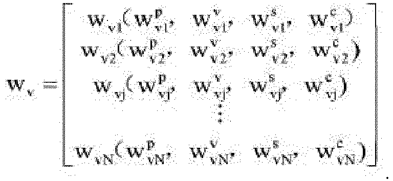
- It is easily understood that, if a ratio of the confidence factor of the roadside sensing apparatus to the confidence factor of the vehicle sensing apparatus is larger, a ratio of a proportion of the roadside sensing data in the fusion result to a proportion of the vehicle sensing data in the fusion result is larger. Simply, if a value of a confidence factor of a sensing apparatus is larger, a proportion of sensing data obtained by the sensing apparatus through detection in the fusion result is larger.
- It should be noted that, the confidence factor may be determined based on a sensing apparatus parameter, a sensing distance of the target object, and a sensing angle of the target object together. The sensing apparatus parameter is related to initial precision, a spatial installation angle, and installation coordinates of the sensing apparatus. The sensing distance of the target object is a distance between the target object and the sensing apparatus in a sensing coordinate system. The sensing angle of the target object is an angle formed between the target object and the sensing apparatus in the sensing coordinate system. It should be noted that, when the sensing apparatus includes a plurality of sensors, the confidence factor may be obtained in a manner of weighting or averaging by comprehensively considering confidence of the plurality of sensors. In a specific embodiment, the confidence factor may be obtained based on the following formula:

- In a specific embodiment, the sensing apparatus parameter may be obtained based on the following formula: Sk = h (S0, A, P), where Sk is the sensing apparatus parameter, S0 is the initial precision of the sensing apparatus parameter, A is the spatial installation angle of the sensing apparatus, that is, a spatial angle relative to ground of the road after the sensing apparatus is installed, and P is the installation coordinates of the sensing apparatus, that is, three-dimensional coordinates relative to the ground of the road after the sensing apparatus is installed.
- Optionally, the spatial installation angle of the sensing apparatus may be defined as: A = (yaw, pitch, roll), where yaw is a yaw angle of the sensing apparatus relative to the ground of the road, pitch is a pitch angle of the sensing apparatus relative to the ground of the road, and roll is a roll angle of the sensing apparatus relative to the ground of the road. As shown in
FIG. 2 , in an example in which right-handed Cartesian coordinates are created relative to the ground of the road, the yaw angle yaw may be defined as an angle obtained by rotating the sensing apparatus around a y-axis, the pitch angle pitch may be defined as an angle obtained by rotating the sensing apparatus around an x-axis, and the roll angle roll may be defined as an angle obtained by rotating the sensing apparatus around a z-axis. - Optionally, the installation coordinates of the sensing apparatus may be defined as: P = (x, y, h). As shown in
FIG. 3 , x and y indicate coordinates of the sensing apparatus projected on the ground of the road, and h indicates a vertical distance from the sensing apparatus to the ground of the road. - In a specific embodiment, the sensing distance of the target object and the sensing angle of the target object may be obtained in the following manner: As shown in
FIG. 4 , using the sensing apparatus as a center, the sensing range of the sensing apparatus is divided into sector areas of different distances and different angles, so that a sensing coordinate system is created. The sensing apparatus determines the sensing distance Ri of the target object and the sensing angle θj of the target object based on a sector area within which the target object falls in the sensing coordinate system. - Before performing data fusion on the roadside sensing data and the vehicle sensing data to obtain the fusion result, the roadside device and/or the vehicle device need/needs to match the roadside sensing data with the vehicle sensing data to obtain a matching result, so that the roadside device and/or the vehicle device can perform data fusion on the roadside sensing data and the vehicle sensing data based on the matching result.
- The following uses an example to describe a meaning of matching the roadside sensing data with the vehicle sensing data. It is assumed that the roadside sensing data expressed in the form of the roadside result set is: resultr (roadside1, roadside2, ..., roadsideM), and that the vehicle sensing data expressed in the form of the vehicle result set is: resultv (vehicle1, vehicle2, ..., vehicleN), where M is the quantity of the target objects in the sensing range of the roadside sensing apparatus, N is the quantity of the target objects in the sensing range of the vehicle sensing apparatus, and M > N, where roadside1 is a roadside result unit obtained by the roadside sensing apparatus by detecting a target object 1, roadside2 is a roadside result unit obtained by the roadside sensing apparatus by detecting a target object 1, ..., and roadsideM is a roadside result unit obtained by the roadside sensing apparatus by detecting a target object M; and vehiclei is a vehicle result unit obtained by the vehicle sensing apparatus by detecting the target object 1, vehicle2 is a vehicle result unit obtained by the vehicle sensing apparatus by detecting the target object 1, ..., and vehicleN is a vehicle result unit obtained by the vehicle sensing apparatus by detecting a target object N. Therefore, roadside1 and vehicle1 are both result units obtained by detecting the target object 1, and have a matching relationship; roadside2 and vehicle2 are both result units obtained by detecting the target object 2, and have a matching relationship; ...; roadsideN and vehicleN are both result units obtained by detecting the target object N, and have a matching relationship. Therefore, matching the roadside sensing data with the vehicle sensing data is finding out all matching relationships between roadside result units in the roadside sensing data and vehicle result units in the vehicle sensing data.
- In this embodiment of this application, the roadside device and/or the vehicle device may find out a matching relationship between a roadside result unit in the roadside sensing data and a vehicle result unit in the vehicle sensing data by using a deviation network. Specifically, the roadside result unit and the vehicle result unit are used as an input of the deviation network. In this case, the deviation network outputs a matching result between the roadside result unit and the vehicle result unit. If the matching result output by the deviation network is that the roadside result unit matches the vehicle result unit, it may be considered that the matching relationship exists between the roadside result unit and the vehicle result unit; or if the matching result output by the deviation network is that the roadside result unit does not match the vehicle result unit, it may be considered that the matching relationship does not exist between the roadside result unit and the vehicle result unit. Still using the foregoing example as an example, if roadside1 and vehiclei are used as an input of the deviation network, and a matching result output by the deviation network is that roadsidei matches vehicle1, it may be determined that a matching relationship exists between roadside1 and vehicle1; or if roadside1 and vehicle2 are used as an input of the deviation network, and a matching result output by the deviation network is that roadsidei does not match vehicle2, it may be determined that a matching relationship does not exist between roadsidei and vehicle2.
- In this embodiment of this application, the matching relationship between the roadside result unit in the roadside sensing data and the vehicle result unit in the vehicle sensing data may be found out by using the following formula: S = Deviation (roadsidei, vehiclej), where S is a matching result, Deviation is the deviation network, roadsidei is the roadside result unit corresponding to the target object i in the sensing range of the roadside sensing apparatus, vehiclej is the vehicle result unit corresponding to the target object j in the sensing range of the vehicle sensing apparatus, and both i and j are natural numbers.
- Using roadsidei = (pri, vri, sri, cri) and vehiclej - (pvj, vvj, svj, cvj) as an example, in a specific implementation, the deviation network Deviation may be expressed by using a back propagation (back propagation, BP) neural network shown in
FIG. 5 , where - Δpij is a position deviation, Δpij = fabs (pri - pvj), pri is a position of the target object i detected by the roadside sensing apparatus, pvj is a position of the target object j detected by the vehicle sensing apparatus, and fabs is a function for obtaining an absolute value;
- Δvij is a speed deviation, Δvij = fabs (vri - vvj), vri is a speed of the target object i detected by the roadside sensing apparatus, and vvj is a speed of the target object j detected by the vehicle sensing apparatus;
- Δsij is a size deviation, Δsij = fabs (sri - svj), sri is a size of the target object i detected by the roadside sensing apparatus, and svj is a size of the target object j detected by the vehicle sensing apparatus;
- Δcij is a color deviation, Δcij = fabs (cri - cvj), cri is a color of the target object i detected by the roadside sensing apparatus, and cvj is a color of the target object j detected by the vehicle sensing apparatus;
- Pp is a position deviation factor,
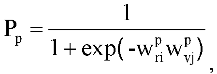


- Pv is a speed deviation factor,


- Ps is a size deviation factor,


- Pc is a speed deviation factor,


- ϕ(.) is an activation function, where the activation function may be a leaky rectified linear unit (Leaky Rectified Linear Unit, LReLU), a parameteric rectified linear unit (Parameteric Rectified Linear Unit, PReLU), a randomized leaky rectified linear unit (Randomized Leaky Rectified Linear Unit, RReLU), a ReLUSoftplus function, a Softsign function, a Sigmoid function, or a tanh function.
- It should be noted that, for a method for obtaining


- In the foregoing example, the deviation network is described by using the BP neural network as an example. Alternatively, in another implementation, the deviation network may be a long short-term memory (Long Short-Term Memory, LSTM) network, a residual network (Residential Networking, ResNet), a recurrent neural network (Recurrent Neural Networks, RNN), or the like. This is not specifically limited herein.
- In the foregoing content, matching is implemented between roadside sensing data and vehicle sensing data in a single frame only, and confidence of a matching result is not high. To resolve the foregoing problem, matching between roadside sensing data and vehicle sensing data in two frames or even more frames may be considered, so that confidence of a matching result is improved. Further, the roadside device and/or the vehicle device may further evaluate confidence of the matching result in a manner of interframe loopback and/or multiframe correlation to obtain an evaluation result, and adjust the deviation network based on the evaluation result.
- In this embodiment of this application, the interframe loopback is mainly obtained through calculation based on a matching result obtained by cross-matching between roadside sensing data and vehicle sensing data in adjacent frames. Using a result unit as an example, the interframe loopback is mainly obtained based on an intraframe matching result and an interframe matching result of adjacent frames. The intraframe matching result is a matching result obtained by matching result units that are obtained by different sensing apparatuses by detecting a same target object in a same frame. The interframe matching result is a matching result obtained by matching result units that are obtained by a same sensing apparatus by detecting a same target object in adjacent frames.
- Using the roadside sensing apparatus and the vehicle sensing apparatus as an example, as shown in
FIG. 6 , the interframe loopback may be defined as: Tloopback = T1 + T2 + T3 + T4, where Tloopback is the interframe loopback, T1 is a first matching result, T2 is a second matching result, T3 is a third matching result, and T4 is a fourth matching result. The first matching result is an intraframe matching result of an ith frame, that is, a matching result between a roadside result unit corresponding to the target object j detected by the roadside sensing apparatus in the ith frame and a vehicle result unit corresponding to the target object j detected by the vehicle sensing apparatus in the ith frame. The second matching result is an interframe matching result of the vehicle sensing apparatus, that is, a matching result between the vehicle result unit corresponding to the target object j detected by the vehicle sensing apparatus in the ith frame and a vehicle result unit corresponding to the target object j detected by the vehicle sensing apparatus in an (i+1)th frame. The third matching result is an intraframe matching result of the (i+1)th frame, that is, a matching result between the vehicle result unit corresponding to the target object j detected by the vehicle sensing apparatus in the (i+1)th frame and a roadside result unit corresponding to the target object j detected by the roadside sensing apparatus in the (i+1)th frame. The fourth matching result is an interframe matching result of the roadside sensing apparatus, that is, a matching result between the roadside result unit corresponding to the target object j detected by the roadside sensing apparatus in the (i+1)th frame and the roadside result unit corresponding to the target object j detected by the roadside sensing apparatus in the ith frame. - In this embodiment of this application, the multiframe correlation is mainly obtained based on interframe loopback between a plurality of consecutive frames. In a specific implementation, as shown in
FIG. 7 , the multiframe correlation may be defined as Tmultiframe = Tloopback12 + Tloopback23 + Tloopback34 + ..., where Tmultiframe is the multiframe correlation, Tloopback12 is interframe loopback between a first frame and a second frame, Tloopback23 is interframe loopback between the second frame and a third frame, Tloopback34 is interframe loopback between the third frame and a fourth frame, ..., and so on. - It is easily understood that, the data fusion performed by the roadside device and/or the vehicle device brings at least the following two benefits:
- 1. Overlapping can be implemented between the sensing range of the roadside sensing apparatus and the sensing range of the vehicle sensing apparatus, so that the sensing range of the roadside sensing apparatus and/or the vehicle sensing apparatus is effectively extended. For example, assuming that the quantity of the target objects detected by the roadside sensing apparatus in the sensing range is 3 (
target object 1, target object 2, and target object 3), and that the quantity of the target objects detected by the vehicle sensing apparatus in the sensing range is 2 (target object 3 and target object 4), after the vehicle sensing apparatus fuses the roadside sensing data and the vehicle sensing data, the sensing range of the fusion result includes four target objects (target object 1, target object 2, target object 3, and target object 4). - 2. Low-confidence data can be corrected by using high-confidence data, so that confidence of data of the roadside sensing apparatus and/or the vehicle sensing apparatus is effectively improved. For example, assuming that confidence of a speed of a target object obtained by the roadside sensing apparatus through measurement is lower than confidence of a speed of a target object obtained by the vehicle sensing apparatus through measurement, the roadside sensing apparatus may use the speed of the target object obtained by the vehicle sensing apparatus through measurement to correct the speed of the target object obtained by the roadside sensing apparatus through measurement, to obtain high-confidence data.
- The foregoing content of the specification focuses on a solution about how to implement data fusion on the roadside sensing data detected by the roadside sensing apparatus in the sensing range and the vehicle sensing data detected by the vehicle sensing apparatus in the sensing range. The following describes, from perspectives of a data fusion method and a related device, how the roadside sensing apparatus and/or the vehicle sensing apparatus use/uses the foregoing data fusion solution to extend the sensing range.
-
FIG. 8 is a schematic flowchart of a first data fusion method according to an embodiment of this application. As shown inFIG. 8 , the data fusion method in this embodiment of this application specifically includes the following steps:
S101. A vehicle device obtains vehicle sensing data, where the vehicle sensing data is obtained by a vehicle sensing apparatus by sensing a road environment in a sensing range by using a vehicle sensor. - In this embodiment of this application, the vehicle sensing apparatus may be configured for the vehicle sensing device. The vehicle sensing apparatus includes at least one vehicle sensor, for example, a combined inertial navigation, a microwave radar, a millimeter-wave radar, and a camera, and can identify vehicle sensing data of a target object in the sensing range. The vehicle sensing data may include a position, a speed, a size, a color, and the like of the target object.
- It may be understood that, the foregoing several specific examples are only examples of the vehicle sensor, and should not constitute a specific limitation. The vehicle sensing apparatus may use any one of the vehicle sensors alone, or may use any plurality of the vehicle sensors simultaneously.
- S102. A roadside device obtains roadside sensing data, where the roadside sensing data is obtained by a roadside sensing apparatus by sensing a road environment in a sensing range by using a roadside sensor.
- In this embodiment of this application, the roadside sensing apparatus may be configured for the roadside device. The roadside sensing apparatus includes at least one roadside sensor, for example, a microwave radar and a millimeter-wave radar, and can identify roadside sensing data of a target object in the sensing range. The roadside sensing data may include a position, a speed, a size, a color, and the like of the target object.
- It may be understood that, the foregoing several specific examples are only examples of the roadside sensor, and should not constitute a specific limitation. The roadside sensing apparatus may use any one of the roadside sensors alone, or may use any plurality of the roadside sensors simultaneously.
- S103. The roadside device sends the roadside sensing data to the vehicle device. Correspondingly, the vehicle device receives the roadside sensing data sent by the roadside device.
- S104. The vehicle device matches the roadside sensing data with the vehicle sensing data to obtain a matching result.
- In this embodiment of this application, the vehicle device may find out a matching relationship between a roadside result unit in the roadside sensing data and a vehicle result unit in the vehicle sensing data by using a deviation network. Specifically, the roadside result unit and the vehicle result unit are used as an input of the deviation network. In this case, the deviation network outputs a matching result between the roadside result unit and the vehicle result unit.
- In this embodiment of this application, the matching relationship between the roadside result unit in the roadside sensing data and the vehicle result unit in the vehicle sensing data may be found out by using the following formula: S = Deviation (roadsidei, vehiclej), where S is a matching result, Deviation is the deviation network, roadsidei is a roadside result unit corresponding to a target object i in the sensing range of the roadside sensing apparatus, vehiclej is a vehicle result unit corresponding to a target object j in the sensing range of the vehicle sensing apparatus, and both i and j are natural numbers.
- S105. The vehicle device evaluates confidence of the matching result in a manner of interframe loopback and/or multiframe correlation, and adjusts the deviation network based on an evaluation result.
- In this embodiment of this application, the interframe loopback may be defined as: Tloopback = T1 + T2 + T3 + T4, where Tloopback is the interframe loopback, T1 is a first matching result, T2 is a second matching result, T3 is a third matching result, and T4 is a fourth matching result. The first matching result is an intraframe matching result of an ith frame, that is, a matching result between a roadside result unit corresponding to the target object j detected by the roadside sensing apparatus in the ith frame and a vehicle result unit corresponding to the target object j detected by the vehicle sensing apparatus in the ith frame. The second matching result is an interframe matching result of the vehicle sensing apparatus, that is, a matching result between the vehicle result unit corresponding to the target object j detected by the vehicle sensing apparatus in the ith frame and a vehicle result unit corresponding to the target object j detected by the vehicle sensing apparatus in an (i+1)th frame. The third matching result is an intraframe matching result of the (i+1)th frame, that is, a matching result between the vehicle result unit corresponding to the target object j detected by the vehicle sensing apparatus in the (i+1)th frame and a roadside result unit corresponding to the target object j detected by the roadside sensing apparatus in the (i+1)th frame. The fourth matching result is an interframe matching result of the roadside sensing apparatus, that is, a matching result between the roadside result unit corresponding to the target object j detected by the roadside sensing apparatus in the (i+1)th frame and the roadside result unit corresponding to the target object j detected by the roadside sensing apparatus in the ith frame.
- In this embodiment of this application, the multiframe correlation is mainly obtained based on interframe loopback between a plurality of consecutive frames. In a specific implementation, the multiframe correlation may be defined as Tmultiframe = Tloopback2 + Tloopback23 + Tloopback34 + ..., where Tmultiframe is the multiframe correlation, Tloopback2 is interframe loopback between a first frame and a second frame, Tloopback23 is interframe loopback between the second frame and a third frame, Tloopback34 is interframe loopback between the third frame and a fourth frame, ..., and so on.
- S106. The vehicle device fuses the vehicle sensing data and the roadside sensing data by using a fusion formula, to obtain a first fusion result.
- In this embodiment of this application, the vehicle device may perform, by using the fusion formula, data fusion on the roadside sensing data detected by the roadside sensing apparatus in the sensing range and the vehicle sensing data detected by the vehicle sensing apparatus in the sensing range, to obtain the first fusion result.
- In this embodiment of this application, the fusion formula may be expressed as y = f (resultr, resultv), where resultr is a roadside result set, resultv is a vehicle result set, y is the first fusion result, and f is used to obtain the first fusion result by mapping based on the roadside result set and the vehicle result set.
- In a specific implementation, the function f may be expressed as:

- For brevity, fusion of the roadside sensing data and the vehicle sensing data is not described in detail again in this embodiment of this application. For details, refer to the descriptions about fusion of the roadside sensing data and the vehicle sensing data at the beginning of the specification.
-
FIG. 9 is a schematic flowchart of a second data fusion method according to an embodiment of this application. As shown inFIG. 9 , the data fusion method in this embodiment of this application specifically includes the following steps:
S201. A roadside device obtains roadside sensing data, where the roadside sensing data is obtained by a roadside sensing apparatus by sensing a road environment in a sensing range by using a roadside sensor. - In this embodiment of this application, the roadside sensing apparatus may be configured for the roadside device. The roadside sensing apparatus includes at least one roadside sensor, for example, a microwave radar and a millimeter-wave radar, and can identify roadside sensing data of a target object in the sensing range. The roadside sensing data may include a position, a speed, a size, a color, and the like of the target object.
- It may be understood that, the foregoing several specific examples are only examples of the roadside sensor, and should not constitute a specific limitation. The roadside sensing apparatus may use any one of the roadside sensors alone, or may use any plurality of the roadside sensors simultaneously.
- S202. A vehicle device obtains vehicle sensing data, where the vehicle sensing data is obtained by a vehicle sensing apparatus by sensing a road environment in a sensing range by using a vehicle sensor.
- In this embodiment of this application, the vehicle sensing apparatus may be configured for the vehicle device. The vehicle sensing apparatus includes at least one vehicle sensor, for example, a combined inertial navigation, a microwave radar, a millimeter-wave radar, and a camera, and can identify vehicle sensing data of a target object in the sensing range. The vehicle sensing data may include a position, a speed, a size, a color, and the like of the target object.
- It may be understood that, the foregoing several specific examples are only examples of the vehicle sensor, and should not constitute a specific limitation. The vehicle sensing apparatus may use any one of the vehicle sensors alone, or may use any plurality of the vehicle sensors simultaneously.
- S203. The vehicle device sends the vehicle sensing data to the roadside device. Correspondingly, the roadside device receives the vehicle sensing data sent by the vehicle device.
- S204. The roadside device matches the roadside sensing data with the vehicle sensing data to obtain a matching result.
- In this embodiment of this application, the roadside sensing apparatus may find out a matching relationship between a roadside result unit in the roadside sensing data and a vehicle result unit in the vehicle sensing data by using a deviation network. Specifically, the roadside result unit and the vehicle result unit are used as an input of the deviation network. In this case, the deviation network outputs a matching result between the roadside result unit and the vehicle result unit.
- In this embodiment of this application, the matching relationship between the roadside result unit in the roadside sensing data and the vehicle result unit in the vehicle sensing data may be found out by using the following formula: S = Deviation (roadsidei, vehiclej), where S is a matching result, Deviation is the deviation network, roadsidei is a roadside result unit corresponding to a target object i in the sensing range of the roadside sensing apparatus, vehiclej is a vehicle result unit corresponding to a target object j in the sensing range of the vehicle sensing apparatus, and both i and j are natural numbers.
- S205. The roadside device evaluates confidence of the matching result in a manner of interframe loopback and/or multiframe correlation to obtain an evaluation result, and adjusts the deviation network based on the evaluation result.
- In this embodiment of this application, the interframe loopback may be defined as: Tloopback = T1 + T2 + T3 + T4, where Tloopback is the interframe loopback, T1 is a first matching result, T2 is a second matching result, T3 is a third matching result, and T4 is a fourth matching result. The first matching result is an intraframe matching result of an ith frame, that is, a matching result between a roadside result unit corresponding to the target object j detected by the roadside sensing apparatus in the ith frame and a vehicle result unit corresponding to the target object j detected by the vehicle sensing apparatus in the ith frame. The second matching result is an interframe matching result of the vehicle sensing apparatus, that is, a matching result between the vehicle result unit corresponding to the target object j detected by the vehicle sensing apparatus in the ith frame and a vehicle result unit corresponding to the target object j detected by the vehicle sensing apparatus in an (i+1)th frame. The third matching result is an intraframe matching result of the (i+1)th frame, that is, a matching result between the vehicle result unit corresponding to the target object j detected by the vehicle sensing apparatus in the (i+1)th frame and a roadside result unit corresponding to the target object j detected by the roadside sensing apparatus in the (i+1)th frame. The fourth matching result is an interframe matching result of the roadside sensing apparatus, that is, a matching result between the roadside result unit corresponding to the target object j detected by the roadside sensing apparatus in the (i+1)th frame and the roadside result unit corresponding to the target object j detected by the roadside sensing apparatus in the ith frame.
- In this embodiment of this application, the multiframe correlation is mainly obtained based on interframe loopback between a plurality of consecutive frames. In a specific implementation, the multiframe correlation may be defined as Tmultiframe = Tloopback2 + Tloopback23 + Tloopback34 + ..., where Tmultiframe is the multiframe correlation, Tloopback2 is interframe loopback between a first frame and a second frame, Tloopback23 is interframe loopback between the second frame and a third frame, Tloopback34 is interframe loopback between the third frame and a fourth frame, ..., and so on.
- S206. The roadside device fuses the vehicle sensing data and the roadside sensing data by using a fusion formula, to obtain a first fusion result.
- In this embodiment of this application, the roadside sensing apparatus may perform, by using the fusion formula, data fusion on the roadside sensing data detected by the roadside sensing apparatus in the sensing range and the vehicle sensing data detected by the vehicle sensing apparatus in the sensing range, to obtain the first fusion result.
- In this embodiment of this application, the fusion formula may be expressed as y = f (resultr, resultv), where resultr is a roadside result set, resultv is a vehicle result set, y is the first fusion result, and f is used to obtain the first fusion result by mapping based on the roadside result set and the vehicle result set.
- In a specific implementation, the function f may be expressed as:

- For brevity, fusion of the roadside sensing data and the vehicle sensing data is not described in detail again in this embodiment of this application. For details, refer to the descriptions about fusion of the roadside sensing data and the vehicle sensing data at the beginning of the specification.
-
FIG. 10 is a schematic flowchart of a third data fusion method according to an embodiment of this application. As shown inFIG. 10 , the data fusion method in this embodiment of this application specifically includes the following steps:
S301. A roadside device obtains roadside sensing data, where the roadside sensing data is obtained by a roadside sensing apparatus by sensing a road environment in a sensing range by using a roadside sensor. - In this embodiment of this application, the roadside sensing apparatus may be configured for the roadside device. The roadside sensing apparatus includes at least one roadside sensor, for example, a microwave radar and a millimeter-wave radar, and can identify roadside sensing data of a target object in the sensing range. The roadside sensing data may include a position, a speed, a size, a color, and the like of the target object.
- It may be understood that, the foregoing several specific examples are only examples of the roadside sensor, and should not constitute a specific limitation. The roadside sensing apparatus may use any one of the roadside sensors alone, or may use any plurality of the roadside sensors simultaneously.
- S302. At least one vehicle device obtains vehicle sensing data, where the vehicle sensing data is obtained by a vehicle sensing apparatus by sensing a road environment in a sensing range by using a vehicle sensor.
- In this embodiment of this application, the vehicle sensing apparatus may be configured for the vehicle device. The vehicle sensing apparatus includes at least one vehicle sensor, for example, a combined inertial navigation, a microwave radar, a millimeter-wave radar, and a camera, and can identify vehicle sensing data of a target object in the sensing range. The vehicle sensing data may include a position, a speed, a size, a color, and the like of the target object.
- It may be understood that, the foregoing several specific examples are only examples of the vehicle sensor, and should not constitute a specific limitation. The vehicle sensing apparatus may use any one of the vehicle sensors alone, or may use any plurality of the vehicle sensors simultaneously.
- S303. The at least one vehicle device sends the vehicle sensing data to the roadside device. Correspondingly, the roadside device receives the vehicle sensing data sent by the at least one vehicle device.
- S304. The roadside device matches the roadside sensing data with the vehicle sensing data sent by the at least one vehicle device, to obtain a matching result.
- In this embodiment of this application, the roadside device may find out a matching relationship between a roadside result unit in the roadside sensing data and a vehicle result unit in the vehicle sensing data by using a deviation network. Specifically, the roadside result unit and the vehicle result unit are used as an input of the deviation network. In this case, the deviation network outputs a matching result between the roadside result unit and the vehicle result unit.
- In this embodiment of this application, the matching relationship between the roadside result unit in the roadside sensing data and the vehicle result unit in the vehicle sensing data may be found out by using the following formula: S = Deviation (roadsidei, vehiclej), where S is a matching result, Deviation is the deviation network, roadsidei is a roadside result unit corresponding to a target object i in the sensing range of the roadside sensing apparatus, vehiclej is a vehicle result unit corresponding to a target object j in the sensing range of the vehicle sensing apparatus, and both i and j are natural numbers.
- S305. The roadside device evaluates confidence of the matching result in a manner of interframe loopback and/or multiframe correlation to obtain an evaluation result, and adjusts the deviation network based on the evaluation result.
- In this embodiment of this application, the interframe loopback may be defined as: Tloopback = T1 + T2 + T3 + T4, where Tloopback is the interframe loopback, T1 is a first matching result, T2 is a second matching result, T3 is a third matching result, and T4 is a fourth matching result. The first matching result is an intraframe matching result of an ith frame, that is, a matching result between a roadside result unit corresponding to the target object j detected by the roadside sensing apparatus in the ith frame and a vehicle result unit corresponding to the target object j detected by the vehicle sensing apparatus in the ith frame. The second matching result is an interframe matching result of the vehicle sensing apparatus, that is, a matching result between the vehicle result unit corresponding to the target object j detected by the vehicle sensing apparatus in the ith frame and a vehicle result unit corresponding to the target object j detected by the vehicle sensing apparatus in an (i+1)th frame. The third matching result is an intraframe matching result of the (i+1)th frame, that is, a matching result between the vehicle result unit corresponding to the target object j detected by the vehicle sensing apparatus in the (i+1)th frame and a roadside result unit corresponding to the target object j detected by the roadside sensing apparatus in the (i+1)th frame. The fourth matching result is an interframe matching result of the roadside sensing apparatus, that is, a matching result between the roadside result unit corresponding to the target object j detected by the roadside sensing apparatus in the (i+1)th frame and the roadside result unit corresponding to the target object j detected by the roadside sensing apparatus in the ith frame.
- In this embodiment of this application, the multiframe correlation is mainly obtained based on interframe loopback between a plurality of consecutive frames. In a specific implementation, the multiframe correlation may be defined as Tmultiframe = Tloopback2 + Tloopback23 + Tloopback34 + ..., where Tmultiframe is the multiframe correlation, Tloopback2 is interframe loopback between a first frame and a second frame, Tloopback23 is interframe loopback between the second frame and a third frame, Tloopback34 is interframe loopback between the third frame and a fourth frame, ..., and so on.
- S306. The roadside device fuses the vehicle sensing data sent by the at least one vehicle device and the roadside sensing data by using a fusion formula, to obtain a first fusion result.
- In this embodiment of this application, the roadside device may perform, by using the fusion formula, data fusion on the roadside sensing data detected by the roadside sensing apparatus in the sensing range and the vehicle sensing data detected by the vehicle sensing apparatus in the sensing range, to obtain the first fusion result.
- In this embodiment of this application, the fusion formula may be expressed as y = f (resultr, resultv), where resultr is a roadside result set, resultv is a vehicle result set, y is the first fusion result, and f is used to obtain the first fusion result by mapping based on the roadside result set and the vehicle result set.
- In a specific implementation, the function f may be expressed as:

- In this embodiment of this application, the first fusion result may be obtained by the roadside sensing apparatus by fusing vehicle sensing data sent by one or more vehicle sensing apparatuses and the roadside sensing data of the roadside sensing apparatus by using the fusion formula. This is not specifically limited.
- For brevity, fusion of the roadside sensing data and the vehicle sensing data is not described in detail again in this embodiment of this application. For details, refer to the descriptions about fusion of the roadside sensing data and the vehicle sensing data at the beginning of the specification.
- S307. The roadside device sends the first fusion result to a target vehicle device. Correspondingly, the target vehicle device receives the first fusion result sent by the roadside device. The target vehicle device belongs to the at least one vehicle device.
- S308. The target vehicle device fuses the first fusion result and vehicle sensing data of the target vehicle device to obtain a second fusion result.
- In this embodiment of this application, the target vehicle device may perform data fusion on the first fusion result and the vehicle sensing data of the target vehicle device by using a fusion formula, to obtain the second fusion result. The process of fusing the first fusion result and the vehicle sensing data is similar to the process of fusing the roadside sensing data and the vehicle sensing data, and is not described again herein.
- In the foregoing solution, the roadside device may fuse the vehicle sensing data sent by the plurality of vehicle sensing apparatuses and the roadside sensing data of the roadside device to obtain the first fusion result with a wider sensing range (the sensing range herein is a result of overlapping between the sensing range of the roadside sensing apparatus and sensing ranges of the plurality of vehicle sensing apparatuses), and then send the first fusion result to the target vehicle device, so that the target vehicle device fuses the first fusion result and the vehicle sensing data to extend the sensing range of the vehicle sensing apparatus.
- Based on a same inventive concept, an embodiment of this application provides a fusion apparatus, where the device may be applied to a vehicle device, or may be applied to a roadside device. The fusion apparatus may be a chip, a programmable component, a circuit component, a device (that is, the fusion apparatus is a vehicle device or a roadside device), a system, or the like, and is not specifically limited herein.
- As shown in
FIG. 11 , in an example in which the fusion apparatus is a vehicle device, the fusion apparatus 100 includes asensor system 104, acontrol system 106, aperipheral device 108, apower source 110, and acalculation apparatus 112. Thecalculation apparatus 112 may include aprocessor 113 and amemory 114. Thecalculation apparatus 112 may be a controller of the fusion apparatus 100 or a part of a controller. Thememory 114 may include aninstruction 115 that may be run by theprocessor 113, and may further storemap data 116. Components of the fusion apparatus 100 may be configured to work in a manner of interconnection with each other and/or interconnection with other components coupled to various systems. For example, thepower source 110 may supply power for all components of the fusion apparatus 100. The calculation apparatus 111 may be configured to receive data from thesensor system 104, thecontrol system 106, and theperipheral device 108, and control them. - In other examples, the fusion apparatus 100 may include more, fewer, or different systems, and each system may include more, fewer, or different components. In addition, the shown systems and components may be combined or split in any manner.
- The
sensor system 104 may include several sensors configured to sense a road environment in a sensing range of the fusion apparatus 100. As shown in the figure, the sensors of the sensor system include aGPS 126, an IMU (Inertial Measurement Unit, inertial measurement unit) 128, a radio detection and radar ranging (RADAR)unit 130, a laser ranging (LIDAR)unit 132, acamera 134, and anactuator 136 configured to change a position and/or an orientation of a sensor. - The
GPS module 126 may be any sensor configured to estimate a geographical position of a vehicle. Therefore, theGPS module 126 may include a transceiver, and estimate a position of the fusion apparatus 100 relative to the earth based on satellite positioning data. In an example, by using theGPS module 126 and referring to themap data 116, the calculation apparatus 111 may be configured to estimate a position of the fusion apparatus 100 at a lane edge on a road on which the vehicle device can drive. Alternatively, theGPS module 126 may be in another form. - The
IMU 128 may be configured to sense position and orientation changes of the vehicle based on inertial, acceleration, and any combination thereof. In some examples, a combination of sensors may include an accelerometer and a gyro. Other combinations of sensors are also possible. - The
RADAR unit 130 may be considered as an object detection system. TheRADAR unit 130 is configured to use a radio wave to detect a feature of a target object, for example, a distance, a height, a direction, or a speed of an object. TheRADAR unit 130 may be configured to transmit a radio wave or a microwave pulse. The radio wave or the microwave pulse may be reflected by any object in a path of the wave. The object may return a part of energy of the wave to a receiver (for example, a dish antenna or an antenna), and the receiver may also be a part of theRADAR unit 130. TheRADAR unit 130 may be further configured to perform digital signal processing on a received signal (reflected from an object), and may be configured to identify a target object. - Other systems similar to a RADAR are already used in other parts of an electromagnetic spectrum. An example is a LIDAR (light detection and ranging), which may use visible light from a laser instead of a radio wave.
- The
LIDAR unit 132 includes a sensor, where the sensor uses light to sense or detect a target object in the road environment in the sensing range of the fusion apparatus 100. Generally, the LIDAR is an optical remote sensing technology that may use light to illuminate a target to measure a distance to a target object or other attributes of the target object. For example, theLIDAR unit 132 may include a laser source and/or a laser scanner configured to transmit a laser pulse, and a detector configured to receive reflection of the laser pulse. For example, theLIDAR unit 132 may include a laser rangefinder based on reflection by a rotation mirror, and perform laser scanning around a digital scene in one dimension or two dimensions, to collect distance measurement values from a specified angle at specified intervals. In an example, theLIDAR unit 132 may include components such as a light (for example, laser) source, a scanner, an optical system, an optical detector, and a receiver or an electronic component, and a position and navigation system. - In an example, the
LIDAR unit 132 may be configured to use ultraviolet (UV), visible light, or infrared light for object imaging, and may be applied to a wide range of target objects, including non-metallic objects. In an example, a narrow laser beam may be used to draw a map about physical features of an object with a high resolution. - In an example, wavelengths in a range from about 10 microns (infrared) to about 250 nanometers (UV) may be used. Light is generally reflected after backscattering. Different types of scattering, for example, Rayleigh scattering, Mie scattering, Raman scattering, and fluorescent, are used in different LIDAR applications. For example, based on different types of backscattering, the LIDAR may be therefore referred to as a Rayleigh laser RADAR, a Mie LIDAR, a Raman LIDAR, and a sodium/Fe/potassium fluorescent LIDAR. An appropriate combination of wavelengths may allow, for example, remote map drawing for an object by searching for a wavelength-dependent change of strength of a reflected signal.
- Three-dimensional (3D) imaging may be implemented by using a scanning LIDAR system and a non-scanning LIDAR system. "A 3D gated viewing laser RADAR (3D gated viewing laser radar)" is an example of a non-scanning laser ranging system. A pulsed laser and a fast gated camera are applied in the 3D gated viewing laser RADAR. An imaging LIDAR may also be implemented by using a high-speed detector array and a modulation sensitive detector array built on a single chip generally by using CMOS (Complementary Metal Oxide Semiconductor, complementary metal oxide semiconductor) and CCD (Charge Coupled Device, hybrid complementary metal oxide semiconducto/charge coupled device) fabrication techniques. In the apparatuses, each pixel may be locally processed through high-speed demodulation or gating, so that the array can be processed to represent an image from a camera. This technology can be used to simultaneously obtain thousands of pixels to create a 3D point cloud representing an object or a scene detected by the
LIDAR unit 132. - The point cloud may include a group of vertices in a 3D coordinate system. The vertices may be defined, for example, by X, Y, and Z coordinates, and may represent an outer surface of a target object. The
LIDAR unit 132 may be configured to create a point cloud by measuring a large quantity of points on the surface of the target object, and may use the point cloud as a data file for outputting. As a result of a 3D scanning process performed on the object by using theLIDAR unit 132, the point cloud may be used to identify and visualize the target object. - In an example, the point cloud may be directly rendered to visualize the target object. In another example, the point cloud may be converted into a polygonal or triangular grid model in a process that may be referred to as surface reconstruction. Example technologies for converting the point cloud into a 3D surface may include: Delaunay triangulation, alpha shape, and rotating sphere. The technologies include constructing a triangular network on the existing vertices of the point cloud. Other example technologies may include converting the point cloud into a volume distance field, and reconstructing, by using a marching cubes algorithm, an implicit surface defined in this manner.
- The
camera 134 may be any camera (for example, a static camera or a video camera) configured to obtain an image of the road environment in which the vehicle is located. Therefore, the camera may be configured to detect visible light, or may be configured to detect light from other parts of spectrums (for example, infrared light or ultraviolet). Other types of cameras are also possible. Thecamera 134 may be a two-dimensional detector, or may have a three-dimensional space range. In some examples, thecamera 134 may be, for example, a distance detector, and thecamera 134 is configured to generate a two-dimensional image indicating distances from thecamera 134 to several points in the environment. Therefore, thecamera 134 may use one or more distance detection technologies. For example, thecamera 134 may be configured to use a structured light technology. The fusion apparatus 100 uses a predetermined light pattern, for example, a grid or chessboard grid pattern, to illuminate an object in the environment, and uses thecamera 134 to detect reflection of the predetermined light pattern from the object. Based on distortion in the reflected light pattern, the fusion apparatus 100 may be configured to detect a distance to a point on the object. The predetermined light pattern may include infrared light or light of other wavelengths. - The
actuator 136, for example, may be configured to change a position and/or an orientation of a sensor. Thesensor system 104 may additionally or alternatively include a component other than the shown components. - The
control system 106 may be configured to control operations of the fusion apparatus 100 and components of the fusion apparatus 100. Therefore, thecontrol system 106 may include a sensor fusion algorithm 144, a computervisual system 146, a navigation or path control (pathing)system 148, and anobstacle avoidance system 150. - The sensor fusion algorithm 144 may include, for example, an algorithm (or a computer program product storing an algorithm) that the calculation apparatus 111 may run. The sensor fusion algorithm 144 may be configured to accept data from the
sensor 104 as an input. The data may include, for example, data of information detected by a sensor of thesensor system 104. The sensor fusion algorithm 144 may include, for example, a Kalman filter, a Bayesian network, or another algorithm. The sensor fusion algorithm 144 may be further configured to provide various evaluations based on data from thesensor system 104, including, for example, an evaluation on an individual object and/or feature in the environment in which the vehicle is located, an evaluation on a specific situation, and/or an evaluation on possible impact based on a specific situation. Other evaluations are also possible. - The computer
visual system 146 may be any system configured to process and analyze an image captured by thecamera 134, to identify an object and/or a feature in the environment in which the fusion apparatus 100 is located, where the object and/or feature include/includes, for example, lane information, a traffic signal, and an obstacle. Therefore, the computervisual system 146 may use an object identification algorithm, a structure from motion (Structure from Motion, SFM) algorithm, video tracking, or another computer visual technology. In some examples, the computervisual system 146 may be additionally configured to draw an environment map, follow an object, estimate a speed of the object, and the like. - The navigation and path control
system 148 may be any system configured to determine a driving path of the vehicle. The navigation and path controlsystem 148 may be additionally configured to dynamically update the driving path when the vehicle is in an operation. In some examples, the navigation and path controlsystem 148 may be configured to determine the driving path for the vehicle with reference to data from the sensor fusion algorithm 144, theGPS module 126, and one or more predetermined maps. - The
obstacle avoidance system 150 may be any system configured to identify, evaluate, and avoid, or overtake in another manner, an obstacle in the environment in which the vehicle is located. - The
control system 106 may additionally or alternatively include a component other than the shown components. - The
peripheral device 108 may be configured to allow the fusion apparatus 100 to interact with an external sensor, another vehicle, and/or a user. Therefore, theperipheral device 108 may include, for example, a wireless communications system 152, atouchscreen 154, amicrophone 156, and/or aspeaker 158. - The wireless communications system 152 may be any system configured to couple to one or more other vehicles, a sensor, or another entity directly or by using a communications network in a wireless manner. Therefore, the wireless communications system 152 may include an antenna and a chip set configured to communicate with the another vehicle, the sensor, or the another entity directly or by using an air interface. The chip set or the entire wireless communications system 152 may be configured to communicate based on one or more other types of wireless communication (for example, protocols), where the wireless communication is, for example, Bluetooth, a communication protocol described in IEEE 802.11 (including any IEEE 802.11 revision), a cellular technology (for example, GSM, CDMA, UMTS (Universal Mobile Telecommunications System, universal mobile telecommunications system), EV-DO, WiMAX, or LTE (Long Term Evolution, long term evolution), ZigBee, DSRC (Dedicated Short Range Communications, dedicated short range communications), RFID (Radio Frequency Identification, radio frequency identification), and the like. The wireless communications system 152 may also be in another form.
- The
touchscreen 154 may be used by the user to input a command to the fusion apparatus 100. Therefore, thetouchscreen 154 may be configured to sense at least one of a position and motion of a finger of the user through capacitive sensing, resistive sensing, a surface acoustic wave process, or the like. Thetouchscreen 154 can sense the motion of the finger in a direction that is parallel to a surface of the touchscreen or is in a same plane as a surface of the touchscreen, in a direction vertical to a surface of the touchscreen, or in both directions, and can further sense a level of pressure applied to the surface of the touchscreen. Thetouchscreen 154 may include one or more translucent or transparent insulating layers and one or more translucent or transparent conducting layers. Thetouchscreen 154 may also be in another form. - The
microphone 156 may be configured to receive an audio (for example, a voice command or another audio input) from the user of the fusion apparatus 100. Similarly, thespeaker 158 may be configured to output an audio to the user of the fusion apparatus 100. - The
peripheral device 108 may additionally or alternatively include a component other than the shown components. - The
power source 110 may be configured to supply power for some or all of components of the fusion apparatus 100. Therefore, thepower source 110 may include, for example, a rechargeable lithium-ion or lead-acid battery. In some examples, one or more battery groups may be configured to supply power. Other power materials and configurations are also possible. In some examples, thepower source 110 and an energy source 120 may be implemented together, as in an electric vehicle. - The
processor 113 included in the calculation apparatus 111 may include one or more general purpose processors and/or one or more dedicated processors (for example, an image processor or a digital signal processor). If theprocessor 113 includes more than one processor, the processors may work independently or work in combination. The calculation apparatus 111 may implement a function of controlling the vehicle 100 based on an input received by using auser interface 112. - The
memory 114 may further include one or more volatile storage components and/or one or more non-volatile storage components, such as an optical, magnetic, and/or organic storage apparatus, and thememory 114 may be integrated with theprocessor 113 completely or partially. Thememory 114 may include an instruction 115 (for example, program logic) that is run by theprocessor 113, to run various vehicle functions, including any one of the functions or methods described in the specification. - The components of the fusion apparatus 100 may be configured to work in a manner of interconnection with other components in respective systems and/or interconnection with other external components. Therefore, the components and systems of the fusion apparatus 100 may be communicatively interconnected by using a system bus, a network, and/or another connection mechanism.
- In
Embodiment 1, theprocessor 113 of the fusion apparatus 100 executes the following instruction: - obtaining vehicle sensing data, where the vehicle sensing data is obtained by a vehicle sensing apparatus by sensing a road environment in a sensing range;
- obtaining roadside sensing data, where the roadside sensing data is obtained by a roadside sensing apparatus by sensing a road environment in a sensing range; and
- fusing the vehicle sensing data and the roadside sensing data by using a fusion formula, to obtain a first fusion result.
- In Embodiment 2, the
processor 113 of the fusion apparatus 100 executes the following instruction: - sending vehicle sensing data to a roadside device, where the vehicle sensing data is obtained by a vehicle sensing apparatus by sensing a road environment in a sensing range by using a vehicle sensor;
- receiving a first fusion result sent by the roadside device, where the first fusion result is obtained by the roadside device by fusing vehicle sensing data of at least one vehicle device and roadside sensing data by using a fusion formula, and the roadside sensing data is obtained by a roadside sensing apparatus by sensing a road environment in a sensing range; and
- fusing the vehicle sensing data and the first fusion result to obtain a second fusion result.
- With reference to
Embodiment 1 or Embodiment 2, the fusion formula is expressed as:
- In a specific implementation,

- More specifically, the confidence factor is determined based on a sensing apparatus parameter, a sensing distance of the target object, and a sensing angle of the target object together.
- For example, the confidence factor w may be obtained based on the following formula:

- In a specific implementation, the vehicle result set includes at least one vehicle result unit, a one-to-one correspondence exists between the at least one vehicle result unit and at least one target object, and each vehicle result unit in the at least one vehicle result unit is used to describe a feature of a corresponding target object from a multidimensional angle.
- More specifically, one vehicle result unit in the at least one vehicle result unit is expressed as vehiclej (pvj, vvj, svj, cvj), where pvj indicates a position of the target object j detected by the vehicle sensing apparatus, vvj indicates a speed of the target object j detected by the vehicle sensing apparatus, svj indicates a size of the target object j detected by the vehicle sensing apparatus, cvj indicates a color of the target object j detected by the vehicle sensing apparatus, N is the quantity of target objects in the sensing range of the vehicle sensing apparatus, j is a natural number, and 0 < j ≤ N.
- In a specific implementation, the roadside result set includes at least one roadside result unit, a one-to-one correspondence exists between the at least one roadside result unit and at least one target object, and each roadside result unit in the at least one roadside result unit is used to describe a feature of a corresponding target object from a multidimensional angle.
- More specifically, one roadside result unit in the at least one roadside result unit is expressed as roadsidei (pvi, vvi, svi, cvi), where pvi indicates a position of the target object i detected by the roadside sensing apparatus, vvi indicates a speed of the target object i detected by the roadside sensing apparatus, svi indicates a size of the target object i detected by the roadside sensing apparatus, cvi indicates a color of the target object i detected by the roadside sensing apparatus, M is the quantity of target objects in the sensing range of the roadside sensing apparatus, i is a natural number, and 0 < i ≤ M.
- With reference to
Embodiment 1 or Embodiment 2, before the fusing the vehicle sensing data and the roadside sensing data by using a fusion formula, to obtain a first fusion result, the method includes: matching the roadside sensing data with the vehicle sensing data to obtain a matching result; and fusing the vehicle sensing data and the roadside sensing data based on the matching result, to obtain the first fusion result. - In a specific implementation, a matching relationship between a roadside result unit in the roadside result set and a vehicle result unit in the vehicle result set is found out by using a deviation network.
- More specifically, that a matching relationship between a roadside result unit in the roadside result set and a vehicle result unit in the vehicle result set is found out by using a deviation network specifically includes:
finding out the matching relationship between the roadside result unit in the roadside result set and the vehicle result unit in the vehicle result set by using the following formula: S = Deviation (roadsidei, vehiclej), where S is a matching result, Deviation is the deviation network, roadsidei is the roadside result unit corresponding to the target object i in the sensing range of the roadside sensing apparatus, vehiclej is the vehicle result unit corresponding to the target object j in the sensing range of the vehicle sensing apparatus, and both i and j are natural numbers. - In a specific implementation, after the matching the roadside sensing data with the vehicle sensing data to obtain a matching result, the method includes: evaluating confidence of the matching result in a manner of interframe loopback and/or multiframe correlation to obtain an evaluation result; and adjusting the deviation network based on the evaluation result.
- Specifically, the interframe loopback is Tloopback = T1 + T2 + T3 + T4, where Tloopback is the interframe loopback, T1 is a first matching result, T2 is a second matching result, T3 is a third matching result, T4 is a fourth matching result, the first matching result is a matching result between a roadside result unit corresponding to the target object j detected by the roadside sensing apparatus in an ith frame and a vehicle result unit corresponding to the target object j detected by the vehicle sensing apparatus in the ith frame, the second matching result is a matching result between the vehicle result unit corresponding to the target object j detected by the vehicle sensing apparatus in the ith frame and a vehicle result unit corresponding to the target object j detected by the vehicle sensing apparatus in an (i+1)th frame, the third matching result is a matching result between the vehicle result unit corresponding to the target object j detected by the vehicle sensing apparatus in the (i+1)th frame and a roadside result unit corresponding to the target object j detected by the roadside sensing apparatus in the (i+1)th frame, and the fourth matching result is a matching result between the roadside result unit corresponding to the target object j detected by the roadside sensing apparatus in the (i+1)th frame and the roadside result unit corresponding to the target object j detected by the roadside sensing apparatus in the ith frame.
- Specifically, the multiframe correlation is defined as Tmultiframe = Tloopback2 + Tloopback23 + Tloopback34 + ..., where Tmultiframe is the multiframe correlation, Tloopback2 is interframe loopback between a first frame and a second frame, Tloopback23 is interframe loopback between the second frame and a third frame, Tloopback34 is interframe loopback between the third frame and a fourth frame, ....
- It should be noted that, for content not mentioned in the embodiment in
FIG. 11 , reference may be made to the embodiments corresponding toFIG. 8 to FIG. 10 . Details are not described again herein. - As shown in
FIG. 12 , for example, when a fusion apparatus is a roadside device, the fusion apparatus 200 includes components such as an RF (Radio Frequency, radio frequency)circuit 210, amemory 220, anotherinput device 230, adisplay screen 240, asensor system 250, an I/O subsystem 270, aprocessor 280, and apower source 290. A person skilled in the art may understand that a roadside sensing apparatus is not limited to a structure of the roadside sensing apparatus shown inFIG. 12 . The roadside sensing apparatus may include more or fewer parts than that shown in the figure, or some parts are combined, or some parts are split, or an arrangement of parts is different. A person skilled in the art may understand that thedisplay screen 240 may be configured to display a user interface (UI, User Interface). - The following describes each component of the fusion apparatus 200 in detail with reference to
FIG. 12 . - The
RF circuit 210 may be configured to send or receive data. Generally, the RF circuit includes but is not limited to an antenna, at least one amplifier, a transceiver, a coupler, an LNA (Low Noise Amplifier, low noise amplifier), a duplexer, and the like. In addition, theRF circuit 210 may further communicate with a network and other devices through wireless communication. The wireless communication may use any communication standard or protocol, including but not limited to the GSM (Global System of Mobile communications, global system for mobile communications), GPRS (General Packet Radio Service, general packet radio service), CDMA (Code Division Multiple Access, code division multiple access), WCDMA (Wideband Code Division Multiple Access, wideband code division multiple access), LTE (Long Term Evolution, long term evolution), e-mail, SMS (Short Messaging Service, short message service), and the like. - The
memory 220 may include a high-speed random access memory, and may further include a non-volatile memory, for example, at least one magnetic disk storage device, a flash memory, or another volatile solid-state storage device. Thememory 220 may include aninstruction 222 that may be run by theprocessor 280, and may further storemap data 224. - The another
input device 230 may be configured to receive input digit or character information, and generate a key signal input related to a user setting and function control of the fusion apparatus 200. Specifically, the anotherinput device 230 may include but is not limited to one or more of a physical keyboard, a function key (such as a volume control key and a power on/off key), a trackball, a mouse, a joystick, an optical mouse (the optical mouse is a touch-sensitive surface that does not display a visual output, or is an extension of a touch-sensitive surface formed by a touchscreen), and the like. The anotherinput device 230 is connected to anotherinput device controller 271 of the I/O subsystem 270, and is controlled by the anotherinput device controller 271 to perform signal interaction with theprocessor 280. - The
display screen 240 may include adisplay panel 241 and atouch panel 242. For thedisplay panel 241, thedisplay panel 241 may be configured in a form of an LCD (Liquid Crystal Display, liquid crystal display), an OLED (Organic Light-Emitting Diode, organic light-emitting diode), or the like. Thetouch panel 242, also referred to as a touchscreen, a touch-sensitive screen, or the like, may capture a touch or non-touch operation of a user on or near the touch panel (for example, the operation is an operation performed by the user by using any appropriate object or accessory such as a finger or a stylus on thetouch panel 242 or near thetouch panel 242, or may include a motion sensing operation; and an operation type of the operation includes a single-point control operation, or a multipoint control operation, or the like), and drive a corresponding connection apparatus based on a preset program. - The
sensor system 250 may include several sensors configured to sense a road environment in a sensing range of the fusion apparatus 200. As shown in the figure, the sensors of the sensor system include aGPS 251, a radio detection and radar ranging (RADAR)unit 255, a laser ranging (LIDAR)unit 257, acamera 258, and anactuator 259 configured to change a position and/or an orientation of a sensor. Thesensor system 250 is connected to asensor controller 272 of the I/O subsystem 270, and is controlled by thesensor controller 272 to perform interaction with theprocessor 280. - The
GPS module 251 may be any sensor configured to estimate a geographical position of a vehicle. Therefore, theGPS module 251 may include a transceiver, and estimate a position of the fusion apparatus 200 relative to the earth based on satellite positioning data. In an example, the fusion apparatus 200 may be configured to estimate a position of the fusion apparatus 200 on a road by using theGPS module 251 and referring to themap data 224. Alternatively, theGPS module 126 may be in another form. - The
RADAR unit 255 may be considered as an object detection system. TheRADAR unit 255 is configured to use a radio wave to detect a feature of a target object, for example, a distance, a height, a direction, or a speed of an object. TheRADAR unit 255 may be configured to transmit a radio wave or a microwave pulse. The radio wave or the microwave pulse may be reflected by any object in a path of the wave. The object may return a part of energy of the wave to a receiver (for example, a dish antenna or an antenna), and the receiver may also be a part of theRADAR unit 255. TheRADAR unit 255 may be further configured to perform digital signal processing on a received signal (reflected from an object), and may be configured to identify a target object. - Other systems similar to a RADAR are already used in other parts of an electromagnetic spectrum. An example is a LIDAR (light detection and ranging), which may use visible light from a laser instead of a radio wave.
- The
LIDAR unit 257 includes a sensor, where the sensor uses light to sense or detect a target object in the road environment in the sensing range of the fusion apparatus 200. Generally, the LIDAR is an optical remote sensing technology that may use light to illuminate a target to measure a distance to a target object or other attributes of the target object. For example, theLIDAR unit 257 may include a laser source and/or a laser scanner configured to transmit a laser pulse, and a detector configured to receive reflection of the laser pulse. For example, theLIDAR unit 257 may include a laser rangefinder based on reflection by a rotation mirror, and perform laser scanning around a digital scene in one dimension or two dimensions, to collect distance measurement values from a specified angle at specified intervals. In an example, theLIDAR unit 257 may include components such as a light (for example, laser) source, a scanner, an optical system, an optical detector, and a receiver or an electronic component, and a position and navigation system. - In an example, the
LIDAR unit 257 may be configured to use ultraviolet (UV), visible light, or infrared light for object imaging, and may be applied to a wide range of target objects, including non-metallic objects. In an example, a narrow laser beam may be used to draw a map about physical features of an object with a high resolution. - In an example, wavelengths in a range from about 10 microns (infrared) to about 250 nanometers (UV) may be used. Light is generally reflected after backscattering. Different types of scattering, for example, Rayleigh scattering, Mie scattering, Raman scattering, and fluorescent, are used in different LIDAR applications. For example, based on different types of backscattering, the LIDAR may be therefore referred to as a Rayleigh laser RADAR, a Mie LIDAR, a Raman LIDAR, and a sodium/Fe/potassium fluorescent LIDAR. An appropriate combination of wavelengths may allow, for example, remote map drawing for an object by searching for a wavelength-dependent change of strength of a reflected signal.
- Three-dimensional (3D) imaging may be implemented by using a scanning LIDAR system and a non-scanning LIDAR system. "A 3D gated viewing laser RADAR (3D gated viewing laser radar)" is an example of a non-scanning laser ranging system. A pulsed laser and a fast gated camera are applied in the 3D gated viewing laser RADAR. An imaging LIDAR may also be implemented by using a high-speed detector array and a modulation sensitive detector array built on a single chip generally by using CMOS (Complementary Metal Oxide Semiconductor, complementary metal oxide semiconductor) and CCD (Charge Coupled Device, hybrid complementary metal oxide semiconducto/charge coupled device) fabrication techniques. In the apparatuses, each pixel may be locally processed through high-speed demodulation or gating, so that the array can be processed to represent an image from a camera. This technology can be used to simultaneously obtain thousands of pixels to create a 3D point cloud representing an object or a scene detected by the
LIDAR unit 257. - The point cloud may include a group of vertices in a 3D coordinate system. The vertices may be defined, for example, by X, Y, and Z coordinates, and may represent an outer surface of a target object. The
LIDAR unit 257 may be configured to create a point cloud by measuring a large quantity of points on the surface of the target object, and may use the point cloud as a data file for outputting. As a result of a 3D scanning process performed on the object by using theLIDAR unit 257, the point cloud may be used to identify and visualize the target object. - In an example, the point cloud may be directly rendered to visualize the target object. In another example, the point cloud may be converted into a polygonal or triangular grid model in a process that may be referred to as surface reconstruction. Example technologies for converting the point cloud into a 3D surface may include: Delaunay triangulation, alpha shape, and rotating sphere. The technologies include constructing a triangular network on the existing vertices of the point cloud. Other example technologies may include converting the point cloud into a volume distance field, and reconstructing, by using a marching cubes algorithm, an implicit surface defined in this manner.
- The
camera 258 may be any camera (for example, a static camera or a video camera) configured to obtain an image of a road environment in which the vehicle is located. Therefore, the camera may be configured to detect visible light, or may be configured to detect light from other parts of spectrums (for example, infrared light or ultraviolet). Other types of cameras are also possible. Thecamera 258 may be a two-dimensional detector, or may have a three-dimensional space range. In some examples, thecamera 258 may be, for example, a distance detector, and thecamera 258 is configured to generate a two-dimensional image indicating distances from thecamera 258 to several points in the environment. Therefore, thecamera 258 may use one or more distance detection technologies. For example, thecamera 258 may be configured to use a structured light technology. The fusion apparatus 200 uses a predetermined light pattern, for example, a grid or chessboard grid pattern, to illuminate an object in the environment, and uses thecamera 258 to detect reflection of the predetermined light pattern from the object. Based on distortion in the reflected light pattern, theroadside sensing apparatus 258 may be configured to detect a distance to a point on the object. The predetermined light pattern may include infrared light or light of other wavelengths. - The I/
O subsystem 270 is configured to control external input/output devices, and may include the anotherinput device controller 271 and thesensor controller 272. Optionally, one or more other inputcontrol device controllers 271 receive a signal from the anotherinput device 230 and/or send a signal to the anotherinput device 230. The anotherinput device 230 may include a physical button (push button, rocker arm button, or the like), a dial, a slider switch, a joystick, a scroll wheel, or an optical mouse (the optical mouse is a touch-sensitive surface that does not display a visual output, or is an extension of a touch-sensitive surface formed by a touchscreen). It should be noted that, the other inputcontrol device controller 271 may be connected to any one or more of the foregoing devices. Thesensor controller 272 may receive a signal from one ormore sensors 250 and/or send a signal to one ormore sensors 250. - The
processor 280 is a control center of the fusion apparatus 200. Theprocessor 280 is connected to all parts of the entire fusion apparatus 200 by using various interfaces and lines, and executes various functions and data processing of the fusion apparatus 200 by running or executing a software program and/or module stored in thememory 220 and invoking data stored in thememory 220, thereby performing overall monitoring on the fusion apparatus 200. Optionally, theprocessor 280 may include one or more processing units. Preferably, theprocessor 280 may integrate two modem processors, where the modem processors mainly process wireless communication. It may be understood that, alternatively, the modem processors may not be integrated in theprocessor 280. - The fusion apparatus 200 further includes the power source 290 (such as a battery) for supplying power to the components. Preferably, the power source may be logically connected to the
processor 280 by using a power management system, thereby implementing functions such as managing charging, discharging, and power consumption by using the power management system. - In
Embodiment 1, theprocessor 280 of the fusion apparatus 200 executes the following instruction: - obtaining vehicle sensing data, where the vehicle sensing data is obtained by a vehicle sensing apparatus by sensing a road environment in a sensing range;
- obtaining roadside sensing data, where the roadside sensing data is obtained by a roadside sensing apparatus by sensing a road environment in a sensing range; and
- fusing the vehicle sensing data and the roadside sensing data by using a fusion formula, to obtain a first fusion result. In Embodiment 2, the
processor 280 of the fusion apparatus 200 executes the following instruction:- receiving vehicle sensing data sent by at least one vehicle device, where the vehicle sensing data is obtained by a vehicle sensing apparatus by sensing a road environment in a sensing range;
- fusing the vehicle sensing data of the at least one vehicle device and roadside sensing data by using a fusion formula, to obtain a first fusion result, where the roadside sensing data is obtained by a roadside sensing apparatus by sensing a road environment in a sensing range; and
- sending the first fusion result to a target vehicle device, where the target vehicle device is configured to fuse the vehicle sensing data and the first fusion result to obtain a second fusion result, and the target vehicle device belongs to the at least one vehicle device.
- With reference to
Embodiment 1 or Embodiment 2, the fusion formula is expressed as:
- In a specific implementation,

- More specifically, the confidence factor is determined based on a sensing apparatus parameter, a sensing distance of the target object, and a sensing angle of the target object together.
- For example, the confidence factor w may be obtained based on the following formula:

- In a specific implementation, the vehicle result set includes at least one vehicle result unit, a one-to-one correspondence exists between the at least one vehicle result unit and at least one target object, and each vehicle result unit in the at least one vehicle result unit is used to describe a feature of a corresponding target object from a multidimensional angle.
- More specifically, one vehicle result unit in the at least one vehicle result unit is expressed as vehiclej (pvj, vvj, svj, cvj), where pvj indicates a position of the target object j detected by the vehicle sensing apparatus, vvj indicates a speed of the target object j detected by the vehicle sensing apparatus, svj indicates a size of the target object j detected by the vehicle sensing apparatus, cvj indicates a color of the target object j detected by the vehicle sensing apparatus, N is the quantity of target objects in the sensing range of the vehicle sensing apparatus, j is a natural number, and 0 < j ≤ N.
- In a specific implementation, the roadside result set includes at least one roadside result unit, a one-to-one correspondence exists between the at least one roadside result unit and at least one target object, and each roadside result unit in the at least one roadside result unit is used to describe a feature of a corresponding target object from a multidimensional angle.
- More specifically, one roadside result unit in the at least one roadside result unit is expressed as roadsidei (pvi, vvi, svi, cvi), where pvi indicates a position of the target object i detected by the roadside sensing apparatus, vvi indicates a speed of the target object i detected by the roadside sensing apparatus, svi indicates a size of the target object i detected by the roadside sensing apparatus, cvi indicates a color of the target object i detected by the roadside sensing apparatus, M is the quantity of target objects in the sensing range of the roadside sensing apparatus, i is a natural number, and 0 < i ≤ M.
- With reference to
Embodiment 1 or Embodiment 2, before the fusing the vehicle sensing data and the roadside sensing data by using a fusion formula, to obtain a fusion result, the method includes: matching the roadside sensing data with the vehicle sensing data to obtain a matching result; and fusing the vehicle sensing data and the roadside sensing data based on the matching result, to obtain the first fusion result. - In a specific implementation, a matching relationship between a roadside result unit in the roadside result set and a vehicle result unit in the vehicle result set is found out by using a deviation network.
- More specifically, that a matching relationship between a roadside result unit in the roadside result set and a vehicle result unit in the vehicle result set is found out by using a deviation network specifically includes:
finding out the matching relationship between the roadside result unit in the roadside result set and the vehicle result unit in the vehicle result set by using the following formula: S = Deviation (roadsidei, vehiclej), where S is a matching result, Deviation is the deviation network, roadsidei is the roadside result unit corresponding to the target object i in the sensing range of the roadside sensing apparatus, vehiclej is the vehicle result unit corresponding to the target object j in the sensing range of the vehicle sensing apparatus, and both i and j are natural numbers. - In a specific implementation, after the matching the roadside sensing data with the vehicle sensing data to obtain a matching result, the method includes: evaluating confidence of the matching result in a manner of interframe loopback and/or multiframe correlation to obtain an evaluation result; and adjusting the deviation network based on the evaluation result.
- Specifically, the interframe loopback is Tloopback = T1 + T2 + T3 + T4, where Tloopback is the interframe loopback, T1 is a first matching result, T2 is a second matching result, T3 is a third matching result, T4 is a fourth matching result, the first matching result is a matching result between a roadside result unit corresponding to the target object j detected by the roadside sensing apparatus in an ith frame and a vehicle result unit corresponding to the target object j detected by the vehicle sensing apparatus in the ith frame, the second matching result is a matching result between the vehicle result unit corresponding to the target object j detected by the vehicle sensing apparatus in the ith frame and a vehicle result unit corresponding to the target object j detected by the vehicle sensing apparatus in an (i+1)th frame, the third matching result is a matching result between the vehicle result unit corresponding to the target object j detected by the vehicle sensing apparatus in the (i+1)th frame and a roadside result unit corresponding to the target object j detected by the roadside sensing apparatus in the (i+1)th frame, and the fourth matching result is a matching result between the roadside result unit corresponding to the target object j detected by the roadside sensing apparatus in the (i+1)th frame and the roadside result unit corresponding to the target object j detected by the roadside sensing apparatus in the ith frame.
- Specifically, the multiframe correlation is defined as Tmultiframe = Tloopback2 + Tloopback23 + Tloopback34 + ..., where Tmultiframe is the multiframe correlation, Tloopback2 is interframe loopback between a first frame and a second frame, Tloopback23 is interframe loopback between the second frame and a third frame, Tloopback34 is interframe loopback between the third frame and a fourth frame, ....
- It should be noted that, for content not mentioned in the embodiment in
FIG. 12 , reference may be made to the embodiments corresponding toFIG. 8 to FIG. 10 . Details are not described again herein. - Based on a same inventive concept,
FIG. 13 is a schematic structural diagram of a fusion apparatus according to an embodiment of the present invention. As shown inFIG. 13 , thefusion apparatus 300 may include a first obtainingmodule 301, a second obtainingmodule 302, and afusion module 303. - The first obtaining
module 301 is configured to obtain vehicle sensing data, where the vehicle sensing data is obtained by a vehicle sensing apparatus by sensing a road environment in a sensing range. - The second obtaining
module 302 is configured to obtain roadside sensing data, where the roadside sensing data is obtained by a roadside sensing apparatus by sensing a road environment in a sensing range. - The
fusion module 303 is configured to fuse the vehicle sensing data and the roadside sensing data by using a fusion formula, to obtain a first fusion result. - It should be noted that, for content not mentioned in the embodiment in
FIG. 13 and specific implementation of each functional unit, reference may be made to the embodiments corresponding toFIG. 8 andFIG. 9 . Details are not described again herein. - Based on a same inventive concept,
FIG. 14 is a schematic structural diagram of a fusion apparatus according to an embodiment of the present invention. As shown inFIG. 14 , thefusion apparatus 400 in this embodiment includes a sending module 401, a receivingmodule 402, and afusion module 403. - The sending module 401 is configured to send vehicle sensing data to a roadside device, where the vehicle sensing data is obtained by a vehicle sensing apparatus by sensing a road environment in a sensing range.
- The receiving
module 402 is configured to receive a first fusion result sent by the roadside device, where the first fusion result is obtained by the roadside device by fusing vehicle sensing data of at least one vehicle device and roadside sensing data by using a fusion formula, and the roadside sensing data is obtained by a roadside sensing apparatus by sensing a road environment in a sensing range. - The
fusion module 403 is configured to fuse the vehicle sensing data of the at least one vehicle device and the first fusion result to obtain a second fusion result. - It should be noted that, for content not mentioned in the embodiment in
FIG. 14 and specific implementation of each functional unit, reference may be made to the embodiment corresponding toFIG. 10 . Details are not described again herein. - According to the foregoing solutions, the roadside sensing data obtained by the roadside sensing apparatus by sensing and the vehicle sensing data obtained by the vehicle sensing apparatus by sensing are fused to implement overlapping between the sensing range of the roadside sensing apparatus and the sensing range of the vehicle sensing apparatus, so that the sensing range is effectively extended.
- In the several embodiments provided in this application, it should be understood that the disclosed system, terminal, and method may be implemented in other manners. For example, the described apparatus embodiment is merely an example. For example, the unit division is merely logical function division and may be other division in actual implementation. For example, a plurality of units or components may be combined or integrated into another system, or some features may be ignored or may not be performed. In addition, the displayed or discussed mutual couplings or direct couplings or communication connections may be implemented through some interfaces, indirect couplings or communication connections between the apparatuses or units, or electrical connections, mechanical connections, or connections in other forms.
- The units described as separate parts may or may not be physically separate, and parts displayed as units may or may not be physical units, may be located in one position, or may be distributed on a plurality of network units. Some or all of the units may be selected according to actual requirements to achieve the objectives of the solutions of the embodiments of the present invention.
- In addition, functional units in the embodiments of the present invention may be integrated into one processing unit, or each of the units may exist alone physically, or two or more units are integrated into one unit. The integrated unit may be implemented in a form of hardware, or may be implemented in a form of a software functional unit.
- When the integrated unit is implemented in the form of a software functional unit and sold or used as an independent product, the integrated unit may be stored in a computer-readable storage medium. Based on such an understanding, the technical solutions of the present invention essentially, or the part contributing to the prior art, or all or some of the technical solutions may be implemented in the form of a software product. The computer software product is stored in a storage medium and includes several instructions for instructing a computer device (which may be a personal computer, a server, a network device, or the like) to perform all or some of the steps of the methods described in the embodiments of the present invention. The foregoing storage medium includes any medium that can store program code, such as a USB flash drive, a removable hard disk, a read-only memory (ROM, Read-Only Memory), a random access memory (RAM, Random Access Memory), a magnetic disk, or an optical disc.
- The foregoing descriptions are merely specific embodiments of the present invention, but are not intended to limit the protection scope of the present invention. Any modification or replacement readily figured out by a person skilled in the art within the technical scope disclosed in the present invention shall fall within the protection scope of the present invention. Therefore, the protection scope of the present invention shall be subject to the protection scope of the claims.
Claims (38)
- A data fusion method, comprising:obtaining vehicle sensing data, wherein the vehicle sensing data is obtained by a vehicle sensing apparatus by sensing a road environment in a sensing range;obtaining roadside sensing data, wherein the roadside sensing data is obtained by a roadside sensing apparatus by sensing a road environment in a sensing range; andfusing the vehicle sensing data and the roadside sensing data by using a fusion formula, to obtain a first fusion result.
- The method according to claim 1, wherein the fusion formula is expressed as:

- The method according to claim 2, wherein

- The method according to claim 3, wherein the confidence factor is determined based on a sensing apparatus parameter, a sensing distance of the target object, and a sensing angle of the target object together.
- The method according to claim 4, wherein the confidence factor w may be obtained based on the following formula:

- The method according to any one of claims 2 to 5, wherein the vehicle result set comprises at least one vehicle result unit, a one-to-one correspondence exists between the at least one vehicle result unit and at least one target object, and each vehicle result unit in the at least one vehicle result unit is used to describe a feature of a corresponding target object from a multidimensional angle.
- The method according to claim 6, wherein any vehicle result unit in the at least one vehicle result unit is expressed as vehiclej (pvj, vvj, svj, cvj), wherein pvj indicates a position of the target object j detected by the vehicle sensing apparatus, vvj indicates a speed of the target object j detected by the vehicle sensing apparatus, svj indicates a size of the target object j detected by the vehicle sensing apparatus, cvj indicates a color of the target object j detected by the vehicle sensing apparatus, N is the quantity of target objects in the sensing range of the vehicle sensing apparatus, j is a natural number, and 0 < j ≤ N.
- The method according to any one of claims 2 to 7, wherein the roadside result set comprises at least one roadside result unit, a one-to-one correspondence exists between the at least one roadside result unit and at least one target object, and each roadside result unit in the at least one roadside result unit is used to describe a feature of a corresponding target object from a multidimensional angle.
- The method according to claim 8, wherein any roadside result unit in the at least one roadside result unit is expressed as roadsidei (pvi, vvi, svi, cvi), wherein pvi indicates a position of the target object i detected by the roadside sensing apparatus, vvi indicates a speed of the target object i detected by the roadside sensing apparatus, svi indicates a size of the target object i detected by the roadside sensing apparatus, cvi indicates a color of the target object i detected by the roadside sensing apparatus, M is the quantity of target objects in the sensing range of the roadside sensing apparatus, i is a natural number, and 0 < i ≤ M.
- The method according to any one of claims 2 to 5, wherein before the fusing the vehicle sensing data and the roadside sensing data by using a fusion formula, to obtain a first fusion result, the method further comprises:matching the roadside sensing data with the vehicle sensing data to obtain a matching result; andthe fusing the vehicle sensing data and the roadside sensing data, to obtain a first fusion result comprises:
fusing the vehicle sensing data and the roadside sensing data based on the matching result, to obtain the first fusion result. - The method according to claim 10, wherein the matching the roadside sensing data with the vehicle sensing data to obtain a matching result comprises:
finding out a matching relationship between a roadside result unit in the roadside result set and a vehicle result unit in the vehicle result set by using a deviation network. - The method according to claim 11, wherein the finding out a matching relationship between a roadside result unit in the roadside result set and a vehicle result unit in the vehicle result set by using a deviation network specifically comprises:
finding out the matching relationship between the roadside result unit in the roadside result set and the vehicle result unit in the vehicle result set by using the following formula: S = Deviation (roadsidei, vehiclej), wherein S is a matching result, Deviation is the deviation network, roadsidei is the roadside result unit corresponding to the target object i in the sensing range of the roadside sensing apparatus, vehiclej is the vehicle result unit corresponding to the target object j in the sensing range of the vehicle sensing apparatus, and both i and j are natural numbers. - The method according to claim 12, wherein the deviation network Deviation is a back propagation BP neural network shown in FIG. 5, whereinΔpij is a position deviation, Δpij = fabs (pri - pvj), pri is the position of the target object i detected by the roadside sensing apparatus, pvj is the position of the target object j detected by the vehicle sensing apparatus, and fabs is a function for obtaining an absolute value;Δvij is a speed deviation, Δvij = fabs (vri - vvj), vri is the speed of the target object i detected by the roadside sensing apparatus, and vvj is the speed of the target object j detected by the vehicle sensing apparatus;Δsij is a size deviation, Δsij = fabs (sri - svj), sri is the size of the target object i detected by the roadside sensing apparatus, and svj is the size of the target object j detected by the vehicle sensing apparatus;Δcij is a color deviation, Δcij = fabs (cri - cvj), cri is the color of the target object i detected by the roadside sensing apparatus, and cvj is the color of the target object j detected by the vehicle sensing apparatus; 1Pp is a position deviation factor,


 Pv is a speed deviation factor,

 Ps is a size deviation factor,

 Pc is a speed deviation factor,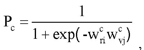

 ϕ(.) is an activation function.
 - The method according to any one of claims 11 to 13, wherein after the matching the roadside sensing data with the vehicle sensing data to obtain a matching result, the method further comprises:evaluating confidence of the matching result in a manner of interframe loopback and/or multiframe correlation to obtain an evaluation result; andadjusting the deviation network based on the evaluation result.
- The method according to claim 14, wherein the interframe loopback is Tloopback = T1 + T2 + T3 + T4, wherein Tloopback is the interframe loopback, T1 is a first matching result, T2 is a second matching result, T3 is a third matching result, T4 is a fourth matching result, the first matching result is a matching result between a roadside result unit corresponding to the target object j detected by the roadside sensing apparatus in an ith frame and a vehicle result unit corresponding to the target object j detected by the vehicle sensing apparatus in the ith frame, the second matching result is a matching result between the vehicle result unit corresponding to the target object j detected by the vehicle sensing apparatus in the ith frame and a vehicle result unit corresponding to the target object j detected by the vehicle sensing apparatus in an (i+1)th frame, the third matching result is a matching result between the vehicle result unit corresponding to the target object j detected by the vehicle sensing apparatus in the (i+1)th frame and a roadside result unit corresponding to the target object j detected by the roadside sensing apparatus in the (i+1)th frame, and the fourth matching result is a matching result between the roadside result unit corresponding to the target object j detected by the roadside sensing apparatus in the (i+1)th frame and the roadside result unit corresponding to the target object j detected by the roadside sensing apparatus in the ith frame.
- The method according to claim 15, wherein the multiframe correlation is defined as Tmultiframe = Tloopback12 + Tloopback23 + Tloopback34 + ..., wherein Tmultiframe is the multiframe correlation, Tloopback12 is interframe loopback between a first frame and a second frame, Tloopback23 is interframe loopback between the second frame and a third frame, Tloopback34 is interframe loopback between the third frame and a fourth frame, ....
- The method according to any one of claims 1 to 16, wherein the obtaining vehicle sensing data comprises:receiving the vehicle sensing data sent by at least one vehicle device; andafter the fusing the vehicle sensing data and the roadside sensing data by using a fusion formula, to obtain a first fusion result, the method further comprises:
sending the first fusion result to a target vehicle device, wherein the target vehicle device is configured to fuse vehicle sensing data of the target vehicle device and the first fusion result to obtain a second fusion result, and the target vehicle device belongs to the at least one vehicle device. - A data fusion method, comprising:sending vehicle sensing data to a roadside device, wherein the vehicle sensing data is obtained by a vehicle sensing apparatus by sensing a road environment in a sensing range;receiving a first fusion result sent by the roadside device, wherein the first fusion result is obtained by the roadside device by fusing vehicle sensing data sent by at least one vehicle device and roadside sensing data by using a fusion formula, and the roadside sensing data is obtained by a roadside sensing apparatus by sensing a road environment in a sensing range; andfusing the vehicle sensing data and the first fusion result to obtain a second fusion result.
- A fusion apparatus, comprising a first obtaining module, a second obtaining module, and a fusion module, wherein
the first obtaining module is configured to obtain vehicle sensing data, wherein the vehicle sensing data is obtained by a vehicle sensing apparatus by sensing a road environment in a sensing range;
the second obtaining module is configured to obtain roadside sensing data, wherein the roadside sensing data is obtained by a roadside sensing apparatus by sensing a road environment in a sensing range; and
the fusion module is configured to fuse the vehicle sensing data and the roadside sensing data by using a fusion formula, to obtain a first fusion result. - The apparatus according to claim 19, wherein the fusion formula is expressed as:

- The apparatus according to claim 20, wherein

- The apparatus according to claim 21, wherein the confidence factor is determined based on a sensing apparatus parameter, a sensing distance of the target object, and a sensing angle of the target object together.
- The apparatus according to claim 22, wherein the confidence factor w may be obtained based on the following formula:

- The apparatus according to any one of claims 20 to 23, wherein the vehicle result set comprises at least one vehicle result unit, a one-to-one correspondence exists between the at least one vehicle result unit and at least one target object, and each vehicle result unit in the at least one vehicle result unit is used to describe a feature of a corresponding target object from a multidimensional angle.
- The apparatus according to claim 24, wherein any vehicle result unit in the at least one vehicle result unit is expressed as vehiclej (pvj, vvj, svj, cvj), wherein pvj indicates a position of the target object j detected by the vehicle sensing apparatus, vvj indicates a speed of the target object j detected by the vehicle sensing apparatus, svj indicates a size of the target object j detected by the vehicle sensing apparatus, cvj indicates a color of the target object j detected by the vehicle sensing apparatus, N is the quantity of target objects in the sensing range of the vehicle sensing apparatus, j is a natural number, and 0 < j ≤ N.
- The apparatus according to any one of claims 20 to 25, wherein the roadside result set comprises at least one roadside result unit, a one-to-one correspondence exists between the at least one roadside result unit and at least one target object, and each roadside result unit in the at least one roadside result unit is used to describe a feature of a corresponding target object from a multidimensional angle.
- The apparatus according to claim 26, wherein any roadside result unit in the at least one roadside result unit is expressed as roadsidei (pvi, vvi, svi, cvi), wherein pvi indicates a position of the target object i detected by the roadside sensing apparatus, vvi indicates a speed of the target object i detected by the roadside sensing apparatus, svi indicates a size of the target object i detected by the roadside sensing apparatus, cvi indicates a color of the target object i detected by the roadside sensing apparatus, M is the quantity of target objects in the sensing range of the roadside sensing apparatus, i is a natural number, and 0 < i ≤ M.
- The apparatus according to any one of claims 20 to 27, wherein the apparatus further comprises a matching module, wherein the matching module is configured to match the roadside sensing data with the vehicle sensing data to obtain a matching result; and the fusion module is further configured to fuse the vehicle sensing data and the roadside sensing data based on the matching result, to obtain the first fusion result.
- The apparatus according to claim 28, wherein the matching module is further configured to find out a matching relationship between a roadside result unit in the roadside result set and a vehicle result unit in the vehicle result set by using a deviation network.
- The apparatus according to claim 29, wherein the matching module is further configured to find out the matching relationship between the roadside result unit in the roadside result set and the vehicle result unit in the vehicle result set by using the following formula: S = Deviation (roadsidei, vehiclej), wherein S is a matching result, Deviation is the deviation network, roadsidei is the roadside result unit corresponding to the target object i in the sensing range of the roadside sensing apparatus, vehiclej is the vehicle result unit corresponding to the target object j in the sensing range of the vehicle sensing apparatus, and both i and j are natural numbers.
- The apparatus according to claim 30, wherein the deviation network Deviation is a back propagation BP neural network shown in FIG. 5, whereinΔpij is a position deviation, Δpij = fabs (pri - pvj), pri is the position of the target object i detected by the roadside sensing apparatus, pvj is the position of the target object j detected by the vehicle sensing apparatus, and fabs is a function for obtaining an absolute value;Δvij is a speed deviation, Δvij = fabs (vri - vvj), vri is the speed of the target object i detected by the roadside sensing apparatus, and vvj is the speed of the target object j detected by the vehicle sensing apparatus;Δsij is a size deviation, Δsij = fabs (sri - svj), sri is the size of the target object i detected by the roadside sensing apparatus, and svj is the size of the target object j detected by the vehicle sensing apparatus;Δcij is a color deviation, Δcij = fabs (cri - cvj), cri is the color of the target object i detected by the roadside sensing apparatus, and cvj is the color of the target object j detected by the vehicle sensing apparatus;Pp is a position deviation factor,
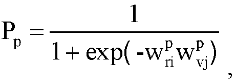

 Pv is a speed deviation factor,

 Ps is a size deviation factor,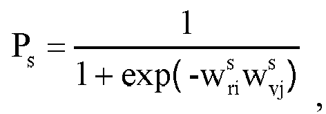

 Pc is a speed deviation factor,

 ϕ(.) is an activation function.
 - The apparatus according to any one of claims 29 to 31, wherein the apparatus further comprises an evaluation module and an adjustment module, wherein
the evaluation module is configured to evaluate confidence of the matching result in a manner of interframe loopback and/or multiframe correlation to obtain an evaluation result; and
the adjustment module is configured to adjust the deviation network based on the evaluation result. - The apparatus according to claim 32, wherein the interframe loopback is Tloopback = T1 + T2 + T3 + T4, wherein Tloopback is the interframe loopback, T1 is a first matching result, T2 is a second matching result, T3 is a third matching result, T4 is a fourth matching result, the first matching result is a matching result between a roadside result unit corresponding to the target object j detected by the roadside sensing apparatus in an ith frame and a vehicle result unit corresponding to the target object j detected by the vehicle sensing apparatus in the ith frame, the second matching result is a matching result between the vehicle result unit corresponding to the target object j detected by the vehicle sensing apparatus in the ith frame and a vehicle result unit corresponding to the target object j detected by the vehicle sensing apparatus in an (i+1)th frame, the third matching result is a matching result between the vehicle result unit corresponding to the target object j detected by the vehicle sensing apparatus in the (i+1)th frame and a roadside result unit corresponding to the target object j detected by the roadside sensing apparatus in the (i+1)th frame, and the fourth matching result is a matching result between the roadside result unit corresponding to the target object j detected by the roadside sensing apparatus in the (i+1)th frame and the roadside result unit corresponding to the target object j detected by the roadside sensing apparatus in the ith frame.
- The apparatus according to claim 32 or 33, wherein the multiframe correlation is defined as Tmultiframe = Tloopback12 + Tloopback23 + Tloopback34 + ..., wherein Tmultiframe is the multiframe correlation, Tloopback12 is interframe loopback between a first frame and a second frame, Tloopback23 is interframe loopback between the second frame and a third frame, Tloopback34 is interframe loopback between the third frame and a fourth frame, ....
- The apparatus according to any one of claims 19 to 34, wherein the apparatus further comprises a sending module, wherein
the first obtaining module is configured to receive the vehicle sensing data sent by at least one vehicle device; and
the sending module is configured to send the first fusion result to a target vehicle device, wherein the target vehicle device is configured to fuse vehicle sensing data of the target vehicle device and the first fusion result to obtain a second fusion result, and the target vehicle device belongs to the at least one vehicle device. - A fusion apparatus, comprising a sending module, a receiving module, and a fusion module, wherein
the sending module is configured to send vehicle sensing data to a roadside device, wherein the vehicle sensing data is obtained by a vehicle sensing apparatus by sensing a road environment in a sensing range;
the receiving module is configured to receive a first fusion result sent by the roadside device, wherein the first fusion result is obtained by the roadside device by fusing vehicle sensing data sent by at least one vehicle device and roadside sensing data by using a fusion formula, and the roadside sensing data is obtained by a roadside sensing apparatus by sensing a road environment in a sensing range; and
the fusion module is configured to fuse the vehicle sensing data and the first fusion result to obtain a second fusion result. - A fusion apparatus, comprising a memory, and a processor and a communications module that are coupled to the memory, wherein the communications module is configured to send data to or receive data from outside, the memory is configured to store program code, and the processor is configured to invoke the program code stored in the memory to perform the method according to any one of claims 1 to 18.
- A computer-readable storage medium, comprising an instruction, wherein when the instruction is run on a fusion apparatus, the fusion apparatus is enabled to perform the method according to any one of claims 1 to 18.
Applications Claiming Priority (2)
| Application Number | Priority Date | Filing Date | Title |
|---|---|---|---|
| CN201810232615.5A CN108762245B (en) | 2018-03-20 | 2018-03-20 | Data fusion method and related equipment |
| PCT/CN2019/078646 WO2019179417A1 (en) | 2018-03-20 | 2019-03-19 | Data fusion method and related device |
Publications (3)
| Publication Number | Publication Date |
|---|---|
| EP3754448A1 true EP3754448A1 (en) | 2020-12-23 |
| EP3754448A4 EP3754448A4 (en) | 2021-04-28 |
| EP3754448B1 EP3754448B1 (en) | 2025-06-25 |
Family
ID=63980561
Family Applications (1)
| Application Number | Title | Priority Date | Filing Date |
|---|---|---|---|
| EP19771774.7A Active EP3754448B1 (en) | 2018-03-20 | 2019-03-19 | Data fusion method and related device |
Country Status (5)
| Country | Link |
|---|---|
| US (1) | US11987250B2 (en) |
| EP (1) | EP3754448B1 (en) |
| JP (1) | JP7386173B2 (en) |
| CN (1) | CN108762245B (en) |
| WO (1) | WO2019179417A1 (en) |
Families Citing this family (34)
| Publication number | Priority date | Publication date | Assignee | Title |
|---|---|---|---|---|
| CN108762245B (en) * | 2018-03-20 | 2022-03-25 | 华为技术有限公司 | Data fusion method and related equipment |
| CN109583505A (en) * | 2018-12-05 | 2019-04-05 | 百度在线网络技术(北京)有限公司 | A kind of object correlating method, device, equipment and the medium of multisensor |
| CN112183715A (en) * | 2019-07-03 | 2021-01-05 | 本田技研工业株式会社 | Sensor fusion |
| CN110164157A (en) * | 2019-07-16 | 2019-08-23 | 华人运通(上海)新能源驱动技术有限公司 | Roadside device, the method for roadside device and bus or train route cooperative system |
| CN110276972A (en) * | 2019-07-16 | 2019-09-24 | 启迪云控(北京)科技有限公司 | A kind of object cognitive method and system based on car networking |
| US11787407B2 (en) * | 2019-07-24 | 2023-10-17 | Pony Ai Inc. | System and method for sensing vehicles and street |
| US11867798B2 (en) * | 2019-09-13 | 2024-01-09 | Samsung Electronics Co., Ltd. | Electronic device including sensor and method of determining path of electronic device |
| CN111079079B (en) * | 2019-11-29 | 2023-12-26 | 北京百度网讯科技有限公司 | Data correction method, device, electronic equipment and computer-readable storage medium |
| CN111209327A (en) * | 2020-01-14 | 2020-05-29 | 南京悠淼科技有限公司 | Multi-sensor distributed sensing interconnection and edge fusion processing system and method |
| CN111583690B (en) * | 2020-04-15 | 2021-08-20 | 北京踏歌智行科技有限公司 | A Curve Collaborative Perception Method Based on 5G for Unmanned Transportation System in Mining Area |
| US20220019225A1 (en) * | 2020-07-14 | 2022-01-20 | Argo AI, LLC | Smart node for autonomous vehicle perception augmentation |
| US20220017115A1 (en) * | 2020-07-14 | 2022-01-20 | Argo AI, LLC | Smart node network for autonomous vehicle perception augmentation |
| CN114200918A (en) * | 2020-08-31 | 2022-03-18 | 罗伯特·博世有限公司 | Method, medium, vehicle-mounted computer and control system for realizing automatic driving |
| CN112085960A (en) * | 2020-09-21 | 2020-12-15 | 北京百度网讯科技有限公司 | Vehicle-road cooperative information processing method, device and equipment and automatic driving vehicle |
| CN112349100B (en) * | 2020-11-09 | 2021-06-04 | 紫清智行科技(北京)有限公司 | Multi-view driving risk assessment method and device based on internet environment |
| CN114639262B (en) * | 2020-12-15 | 2024-02-06 | 北京万集科技股份有限公司 | Method and device for detecting state of sensing device, computer device and storage medium |
| CN113012429B (en) * | 2021-02-23 | 2022-07-15 | 云控智行(上海)汽车科技有限公司 | Vehicle road multi-sensor data fusion method and system |
| CN112884892B (en) * | 2021-02-26 | 2023-05-02 | 武汉理工大学 | Unmanned mine car position information processing system and method based on road side device |
| CN112671935A (en) * | 2021-03-17 | 2021-04-16 | 中智行科技有限公司 | Method for remotely controlling vehicle, road side equipment and cloud platform |
| CN115331421B (en) * | 2021-05-10 | 2024-05-10 | 北京万集科技股份有限公司 | Road side multi-sensing environment sensing method, device and system |
| CN113378704B (en) * | 2021-06-09 | 2022-11-11 | 武汉理工大学 | Multi-target detection method, equipment and storage medium |
| CN113223297B (en) * | 2021-07-09 | 2021-10-08 | 杭州目炬科技有限公司 | Multi-dimensional automatic vehicle identification method |
| CN113655494B (en) * | 2021-07-27 | 2024-05-10 | 上海智能网联汽车技术中心有限公司 | Road side camera and 4D millimeter wave fused target detection method, device and medium |
| CN115690119A (en) * | 2021-07-29 | 2023-02-03 | 华为技术有限公司 | A data processing method and device |
| CN115691099A (en) * | 2021-07-30 | 2023-02-03 | 华为技术有限公司 | Sensing capability information generation method, using method and device |
| CN113655509B (en) * | 2021-08-13 | 2023-07-21 | 中国科学院国家天文台长春人造卫星观测站 | High repetition rate satellite laser ranging real-time control system |
| US11845429B2 (en) * | 2021-09-30 | 2023-12-19 | GM Global Technology Operations LLC | Localizing and updating a map using interpolated lane edge data |
| US11987251B2 (en) | 2021-11-15 | 2024-05-21 | GM Global Technology Operations LLC | Adaptive rationalizer for vehicle perception systems toward robust automated driving control |
| CN114120256B (en) * | 2021-12-01 | 2025-11-21 | 浙江数智交院科技股份有限公司 | Information sensing method, device, system, server and readable storage medium |
| CN114152942B (en) * | 2021-12-08 | 2022-08-05 | 北京理工大学 | Millimeter wave radar and vision second-order fusion multi-classification target detection method |
| CN114596547B (en) * | 2022-01-28 | 2025-04-29 | 北京汽车研究总院有限公司 | Obstacle detection method, device, equipment and medium for autonomous driving vehicle |
| CN114915940B (en) * | 2022-05-13 | 2023-07-21 | 山东高速建设管理集团有限公司 | A vehicle-road communication link matching method, system, device and medium |
| DE102022204770A1 (en) * | 2022-05-16 | 2023-11-16 | Robert Bosch Gesellschaft mit beschränkter Haftung | Method for controlling a robotic device |
| EP4438430A1 (en) * | 2023-03-30 | 2024-10-02 | TomTom International B.V. | Method of controlling vehicle functions, vehicle processing system, vehicle, and machine-readable instruction code |
Family Cites Families (35)
| Publication number | Priority date | Publication date | Assignee | Title |
|---|---|---|---|---|
| US6445983B1 (en) * | 2000-07-07 | 2002-09-03 | Case Corporation | Sensor-fusion navigator for automated guidance of off-road vehicles |
| JP4229358B2 (en) * | 2001-01-22 | 2009-02-25 | 株式会社小松製作所 | Driving control device for unmanned vehicles |
| US6944566B2 (en) * | 2002-03-26 | 2005-09-13 | Lockheed Martin Corporation | Method and system for multi-sensor data fusion using a modified dempster-shafer theory |
| KR20040091788A (en) * | 2003-04-22 | 2004-11-02 | 현대자동차주식회사 | Self-control Traveling System For Expressway and Control Method Thereof |
| US7548184B2 (en) * | 2005-06-13 | 2009-06-16 | Raytheon Company | Methods and apparatus for processing data from multiple sources |
| US7460951B2 (en) * | 2005-09-26 | 2008-12-02 | Gm Global Technology Operations, Inc. | System and method of target tracking using sensor fusion |
| CN101231340A (en) * | 2007-12-29 | 2008-07-30 | 四川川大智胜软件股份有限公司 | Error registration method for processing track amalgamation of multiple radar system |
| JP4565022B2 (en) * | 2008-06-30 | 2010-10-20 | 日立オートモティブシステムズ株式会社 | Traffic information system and traffic information processing method |
| CN101393264B (en) * | 2008-10-12 | 2011-07-20 | 北京大学 | Moving target tracking method and system based on multi-laser scanner |
| CN101807245B (en) * | 2010-03-02 | 2013-01-02 | 天津大学 | Artificial neural network-based multi-source gait feature extraction and identification method |
| CN102508246B (en) | 2011-10-13 | 2013-04-17 | 吉林大学 | Vehicle front obstacle detection and tracking method |
| JP2013182490A (en) * | 2012-03-02 | 2013-09-12 | Sumitomo Electric Ind Ltd | Traffic information conversion device, traffic information system, central server, service server, and traffic information providing method |
| JP2013214225A (en) * | 2012-04-03 | 2013-10-17 | Sumitomo Electric Ind Ltd | Traffic information system, central server, service server and traffic information providing method |
| CN103105611B (en) * | 2013-01-16 | 2016-01-20 | 广东工业大学 | A kind of distributed multi-sensor Intelligent information fusion method |
| CN103226708B (en) * | 2013-04-07 | 2016-06-29 | 华南理工大学 | A kind of multi-model fusion video hand division method based on Kinect |
| EP2865576B1 (en) * | 2013-10-22 | 2018-07-04 | Honda Research Institute Europe GmbH | Composite confidence estimation for predictive driver assistant systems |
| EP2865575B1 (en) * | 2013-10-22 | 2022-08-24 | Honda Research Institute Europe GmbH | Confidence estimation for predictive driver assistance systems based on plausibility rules |
| JP6329642B2 (en) * | 2013-12-10 | 2018-05-23 | エスゼット ディージェイアイ テクノロジー カンパニー リミテッドSz Dji Technology Co.,Ltd | Sensor fusion |
| SG10201906433QA (en) * | 2014-03-07 | 2019-08-27 | Capitalogix Holdings Llc | Systems and methods for allocating capital to trading strategies for big data trading in financial markets |
| US9563808B2 (en) * | 2015-01-14 | 2017-02-07 | GM Global Technology Operations LLC | Target grouping techniques for object fusion |
| CN106503723A (en) * | 2015-09-06 | 2017-03-15 | 华为技术有限公司 | A kind of video classification methods and device |
| CN105446338B (en) * | 2015-12-21 | 2017-04-05 | 福州华鹰重工机械有限公司 | Cloud aids in automatic Pilot method and system |
| CN105741545B (en) * | 2016-03-16 | 2018-07-20 | 山东大学 | A kind of device and method differentiating traffic behavior based on bus GNSS space-time trajectory datas |
| CN105741546B (en) * | 2016-03-18 | 2018-06-29 | 重庆邮电大学 | The intelligent vehicle Target Tracking System and method that roadside device is merged with vehicle sensor |
| US10571913B2 (en) * | 2016-08-05 | 2020-02-25 | Aptiv Technologies Limited | Operation-security system for an automated vehicle |
| US10317901B2 (en) * | 2016-09-08 | 2019-06-11 | Mentor Graphics Development (Deutschland) Gmbh | Low-level sensor fusion |
| CN106447707B (en) * | 2016-09-08 | 2018-11-16 | 华中科技大学 | A kind of image Real-time Registration and system |
| CN107063275B (en) * | 2017-03-24 | 2020-05-12 | 重庆邮电大学 | Intelligent vehicle map fusion system and method based on road side equipment |
| US10692365B2 (en) * | 2017-06-20 | 2020-06-23 | Cavh Llc | Intelligent road infrastructure system (IRIS): systems and methods |
| CN107229690B (en) * | 2017-05-19 | 2019-01-25 | 广州中国科学院软件应用技术研究所 | High-precision dynamic map data processing system and method based on roadside sensors |
| CN107230113A (en) * | 2017-08-01 | 2017-10-03 | 江西理工大学 | A kind of house property appraisal procedure of multi-model fusion |
| CN112731911A (en) * | 2017-09-27 | 2021-04-30 | 北京图森智途科技有限公司 | Road side equipment, vehicle-mounted equipment, and automatic driving sensing method and system |
| US10852426B2 (en) * | 2018-01-12 | 2020-12-01 | Tiejun Shan | System and method of utilizing a LIDAR digital map to improve automatic driving |
| WO2019156956A2 (en) * | 2018-02-06 | 2019-08-15 | Cavh Llc | Intelligent road infrastructure system (iris): systems and methods |
| CN108762245B (en) * | 2018-03-20 | 2022-03-25 | 华为技术有限公司 | Data fusion method and related equipment |
-
2018
- 2018-03-20 CN CN201810232615.5A patent/CN108762245B/en active Active
-
2019
- 2019-03-19 WO PCT/CN2019/078646 patent/WO2019179417A1/en not_active Ceased
- 2019-03-19 EP EP19771774.7A patent/EP3754448B1/en active Active
- 2019-03-19 JP JP2020550669A patent/JP7386173B2/en active Active
-
2020
- 2020-09-15 US US17/021,911 patent/US11987250B2/en active Active
Also Published As
| Publication number | Publication date |
|---|---|
| US20200409372A1 (en) | 2020-12-31 |
| JP7386173B2 (en) | 2023-11-24 |
| EP3754448A4 (en) | 2021-04-28 |
| EP3754448B1 (en) | 2025-06-25 |
| CN108762245B (en) | 2022-03-25 |
| JP2021516401A (en) | 2021-07-01 |
| US11987250B2 (en) | 2024-05-21 |
| WO2019179417A1 (en) | 2019-09-26 |
| CN108762245A (en) | 2018-11-06 |
Similar Documents
| Publication | Publication Date | Title |
|---|---|---|
| US11987250B2 (en) | Data fusion method and related device | |
| CN110967011B (en) | Positioning method, device, equipment and storage medium | |
| US12340593B2 (en) | Vehicle drivable area detection method, system, and autonomous vehicle using the system | |
| US20200348408A1 (en) | Vehicle Positioning Method and Vehicle Positioning Apparatus | |
| CN111324115B (en) | Obstacle position detection fusion method, device, electronic equipment and storage medium | |
| US11828604B2 (en) | Method and apparatus for positioning vehicle, electronic device, and storage medium | |
| CN110488234B (en) | External parameter calibration method, device, equipment and medium for vehicle-mounted millimeter wave radar | |
| RU2656711C2 (en) | Method and system for detecting and tracking of moving objects based on three-dimensional sensor data | |
| CN111177869B (en) | Method, device and equipment for determining sensor layout scheme | |
| JP7166446B2 (en) | System and method for estimating pose of robot, robot, and storage medium | |
| WO2022179207A1 (en) | Window occlusion detection method and apparatus | |
| CN115797401B (en) | Alignment parameter verification method, device, storage medium and electronic equipment | |
| CN111538009A (en) | Radar point marking method and device | |
| CN114528941A (en) | Sensor data fusion method and device, electronic equipment and storage medium | |
| CN117452411A (en) | Obstacle detection method and device | |
| CN114384486A (en) | Data processing method and device | |
| Wang et al. | Intelligent construction activity identification for all-weather site monitoring using 4D millimeter-wave technology | |
| CN115373402A (en) | Loader running control method, device and equipment and storage medium | |
| CN115327571A (en) | Three-dimensional environment obstacle detection system and method based on planar laser radar | |
| CN113917875A (en) | Open general intelligent controller, method and storage medium for autonomous unmanned system | |
| CN119987341B (en) | A path optimization method and related apparatus | |
| CN117055016A (en) | Detection precision testing method and device of sensor and storage medium | |
| CN118494509A (en) | Method and equipment for controlling vehicle based on perception fusion and automatic driving vehicle | |
| Byun et al. | Data transmission for infrared images via Earphone Jack on smartphone | |
| CN118692233A (en) | Lane dead-end detection method, device, electronic device and readable storage medium |
Legal Events
| Date | Code | Title | Description |
|---|---|---|---|
| STAA | Information on the status of an ep patent application or granted ep patent |
Free format text: STATUS: THE INTERNATIONAL PUBLICATION HAS BEEN MADE |
|
| PUAI | Public reference made under article 153(3) epc to a published international application that has entered the european phase |
Free format text: ORIGINAL CODE: 0009012 |
|
| STAA | Information on the status of an ep patent application or granted ep patent |
Free format text: STATUS: REQUEST FOR EXAMINATION WAS MADE |
|
| 17P | Request for examination filed |
Effective date: 20200915 |
|
| AK | Designated contracting states |
Kind code of ref document: A1 Designated state(s): AL AT BE BG CH CY CZ DE DK EE ES FI FR GB GR HR HU IE IS IT LI LT LU LV MC MK MT NL NO PL PT RO RS SE SI SK SM TR |
|
| AX | Request for extension of the european patent |
Extension state: BA ME |
|
| A4 | Supplementary search report drawn up and despatched |
Effective date: 20210330 |
|
| RIC1 | Information provided on ipc code assigned before grant |
Ipc: G05D 1/00 20060101AFI20210324BHEP Ipc: G05D 1/02 20200101ALI20210324BHEP Ipc: G01S 7/00 20060101ALI20210324BHEP Ipc: G01S 7/40 20060101ALI20210324BHEP Ipc: G01S 13/86 20060101ALI20210324BHEP Ipc: G01S 13/931 20200101ALI20210324BHEP Ipc: G01S 17/931 20200101ALI20210324BHEP Ipc: G06K 9/62 20060101ALI20210324BHEP Ipc: B60W 40/04 20060101ALI20210324BHEP |
|
| DAV | Request for validation of the european patent (deleted) | ||
| DAX | Request for extension of the european patent (deleted) | ||
| STAA | Information on the status of an ep patent application or granted ep patent |
Free format text: STATUS: EXAMINATION IS IN PROGRESS |
|
| 17Q | First examination report despatched |
Effective date: 20230718 |
|
| REG | Reference to a national code |
Ref country code: DE Ref legal event code: R079 Ipc: G01S0013860000 Ref country code: DE Ref legal event code: R079 Ref document number: 602019071597 Country of ref document: DE Free format text: PREVIOUS MAIN CLASS: G05D0001000000 Ipc: G01S0013860000 |
|
| GRAP | Despatch of communication of intention to grant a patent |
Free format text: ORIGINAL CODE: EPIDOSNIGR1 |
|
| STAA | Information on the status of an ep patent application or granted ep patent |
Free format text: STATUS: GRANT OF PATENT IS INTENDED |
|
| RIC1 | Information provided on ipc code assigned before grant |
Ipc: G06V 10/80 20220101ALI20250218BHEP Ipc: G06V 20/56 20220101ALI20250218BHEP Ipc: G06F 18/25 20230101ALI20250218BHEP Ipc: G01S 7/00 20060101ALI20250218BHEP Ipc: G01S 7/40 20060101ALI20250218BHEP Ipc: B60W 40/04 20060101ALI20250218BHEP Ipc: G05D 1/00 20060101ALI20250218BHEP Ipc: G01S 17/931 20200101ALI20250218BHEP Ipc: G01S 13/931 20200101ALI20250218BHEP Ipc: G01S 13/86 20060101AFI20250218BHEP |
|
| INTG | Intention to grant announced |
Effective date: 20250228 |
|
| GRAS | Grant fee paid |
Free format text: ORIGINAL CODE: EPIDOSNIGR3 |
|
| GRAA | (expected) grant |
Free format text: ORIGINAL CODE: 0009210 |
|
| STAA | Information on the status of an ep patent application or granted ep patent |
Free format text: STATUS: THE PATENT HAS BEEN GRANTED |
|
| AK | Designated contracting states |
Kind code of ref document: B1 Designated state(s): AL AT BE BG CH CY CZ DE DK EE ES FI FR GB GR HR HU IE IS IT LI LT LU LV MC MK MT NL NO PL PT RO RS SE SI SK SM TR |
|
| REG | Reference to a national code |
Ref country code: GB Ref legal event code: FG4D |
|
| REG | Reference to a national code |
Ref country code: CH Ref legal event code: EP |
|
| REG | Reference to a national code |
Ref country code: CH Ref legal event code: EP |
|
| REG | Reference to a national code |
Ref country code: IE Ref legal event code: FG4D |
|
| REG | Reference to a national code |
Ref country code: DE Ref legal event code: R096 Ref document number: 602019071597 Country of ref document: DE |
|
| PG25 | Lapsed in a contracting state [announced via postgrant information from national office to epo] |
Ref country code: FI Free format text: LAPSE BECAUSE OF FAILURE TO SUBMIT A TRANSLATION OF THE DESCRIPTION OR TO PAY THE FEE WITHIN THE PRESCRIBED TIME-LIMIT Effective date: 20250625 |
|
| REG | Reference to a national code |
Ref country code: LT Ref legal event code: MG9D |
|
| PG25 | Lapsed in a contracting state [announced via postgrant information from national office to epo] |
Ref country code: GR Free format text: LAPSE BECAUSE OF FAILURE TO SUBMIT A TRANSLATION OF THE DESCRIPTION OR TO PAY THE FEE WITHIN THE PRESCRIBED TIME-LIMIT Effective date: 20250926 Ref country code: NO Free format text: LAPSE BECAUSE OF FAILURE TO SUBMIT A TRANSLATION OF THE DESCRIPTION OR TO PAY THE FEE WITHIN THE PRESCRIBED TIME-LIMIT Effective date: 20250925 |
|
| PG25 | Lapsed in a contracting state [announced via postgrant information from national office to epo] |
Ref country code: BG Free format text: LAPSE BECAUSE OF FAILURE TO SUBMIT A TRANSLATION OF THE DESCRIPTION OR TO PAY THE FEE WITHIN THE PRESCRIBED TIME-LIMIT Effective date: 20250625 |
|
| PG25 | Lapsed in a contracting state [announced via postgrant information from national office to epo] |
Ref country code: HR Free format text: LAPSE BECAUSE OF FAILURE TO SUBMIT A TRANSLATION OF THE DESCRIPTION OR TO PAY THE FEE WITHIN THE PRESCRIBED TIME-LIMIT Effective date: 20250625 |
|
| PG25 | Lapsed in a contracting state [announced via postgrant information from national office to epo] |
Ref country code: RS Free format text: LAPSE BECAUSE OF FAILURE TO SUBMIT A TRANSLATION OF THE DESCRIPTION OR TO PAY THE FEE WITHIN THE PRESCRIBED TIME-LIMIT Effective date: 20250925 |
|
| PG25 | Lapsed in a contracting state [announced via postgrant information from national office to epo] |
Ref country code: LV Free format text: LAPSE BECAUSE OF FAILURE TO SUBMIT A TRANSLATION OF THE DESCRIPTION OR TO PAY THE FEE WITHIN THE PRESCRIBED TIME-LIMIT Effective date: 20250625 |
|
| REG | Reference to a national code |
Ref country code: NL Ref legal event code: MP Effective date: 20250625 |
|
| PG25 | Lapsed in a contracting state [announced via postgrant information from national office to epo] |
Ref country code: NL Free format text: LAPSE BECAUSE OF FAILURE TO SUBMIT A TRANSLATION OF THE DESCRIPTION OR TO PAY THE FEE WITHIN THE PRESCRIBED TIME-LIMIT Effective date: 20250625 |
|
| PG25 | Lapsed in a contracting state [announced via postgrant information from national office to epo] |
Ref country code: PT Free format text: LAPSE BECAUSE OF FAILURE TO SUBMIT A TRANSLATION OF THE DESCRIPTION OR TO PAY THE FEE WITHIN THE PRESCRIBED TIME-LIMIT Effective date: 20251027 |
|
| REG | Reference to a national code |
Ref country code: AT Ref legal event code: MK05 Ref document number: 1807012 Country of ref document: AT Kind code of ref document: T Effective date: 20250625 |
|
| PG25 | Lapsed in a contracting state [announced via postgrant information from national office to epo] |
Ref country code: IS Free format text: LAPSE BECAUSE OF FAILURE TO SUBMIT A TRANSLATION OF THE DESCRIPTION OR TO PAY THE FEE WITHIN THE PRESCRIBED TIME-LIMIT Effective date: 20251025 |
|
| PG25 | Lapsed in a contracting state [announced via postgrant information from national office to epo] |
Ref country code: AT Free format text: LAPSE BECAUSE OF FAILURE TO SUBMIT A TRANSLATION OF THE DESCRIPTION OR TO PAY THE FEE WITHIN THE PRESCRIBED TIME-LIMIT Effective date: 20250625 Ref country code: SM Free format text: LAPSE BECAUSE OF FAILURE TO SUBMIT A TRANSLATION OF THE DESCRIPTION OR TO PAY THE FEE WITHIN THE PRESCRIBED TIME-LIMIT Effective date: 20250625 |
|
| PG25 | Lapsed in a contracting state [announced via postgrant information from national office to epo] |
Ref country code: CZ Free format text: LAPSE BECAUSE OF FAILURE TO SUBMIT A TRANSLATION OF THE DESCRIPTION OR TO PAY THE FEE WITHIN THE PRESCRIBED TIME-LIMIT Effective date: 20250625 |
|
| PG25 | Lapsed in a contracting state [announced via postgrant information from national office to epo] |
Ref country code: PL Free format text: LAPSE BECAUSE OF FAILURE TO SUBMIT A TRANSLATION OF THE DESCRIPTION OR TO PAY THE FEE WITHIN THE PRESCRIBED TIME-LIMIT Effective date: 20250625 |
|
| PG25 | Lapsed in a contracting state [announced via postgrant information from national office to epo] |
Ref country code: EE Free format text: LAPSE BECAUSE OF FAILURE TO SUBMIT A TRANSLATION OF THE DESCRIPTION OR TO PAY THE FEE WITHIN THE PRESCRIBED TIME-LIMIT Effective date: 20250625 |
|
| PG25 | Lapsed in a contracting state [announced via postgrant information from national office to epo] |
Ref country code: SK Free format text: LAPSE BECAUSE OF FAILURE TO SUBMIT A TRANSLATION OF THE DESCRIPTION OR TO PAY THE FEE WITHIN THE PRESCRIBED TIME-LIMIT Effective date: 20250625 |
|
| PG25 | Lapsed in a contracting state [announced via postgrant information from national office to epo] |
Ref country code: ES Free format text: LAPSE BECAUSE OF FAILURE TO SUBMIT A TRANSLATION OF THE DESCRIPTION OR TO PAY THE FEE WITHIN THE PRESCRIBED TIME-LIMIT Effective date: 20250625 |
|
| PG25 | Lapsed in a contracting state [announced via postgrant information from national office to epo] |
Ref country code: DK Free format text: LAPSE BECAUSE OF FAILURE TO SUBMIT A TRANSLATION OF THE DESCRIPTION OR TO PAY THE FEE WITHIN THE PRESCRIBED TIME-LIMIT Effective date: 20250625 |
|
| PGFP | Annual fee paid to national office [announced via postgrant information from national office to epo] |
Ref country code: DE Payment date: 20260204 Year of fee payment: 8 |
|
| PG25 | Lapsed in a contracting state [announced via postgrant information from national office to epo] |
Ref country code: IT Free format text: LAPSE BECAUSE OF FAILURE TO SUBMIT A TRANSLATION OF THE DESCRIPTION OR TO PAY THE FEE WITHIN THE PRESCRIBED TIME-LIMIT Effective date: 20250625 |
|
| PLBE | No opposition filed within time limit |
Free format text: ORIGINAL CODE: 0009261 |
|
| STAA | Information on the status of an ep patent application or granted ep patent |
Free format text: STATUS: NO OPPOSITION FILED WITHIN TIME LIMIT |