EP3754392A1 - Universal optical fiber - Google Patents
Universal optical fiber Download PDFInfo
- Publication number
- EP3754392A1 EP3754392A1 EP19189846.9A EP19189846A EP3754392A1 EP 3754392 A1 EP3754392 A1 EP 3754392A1 EP 19189846 A EP19189846 A EP 19189846A EP 3754392 A1 EP3754392 A1 EP 3754392A1
- Authority
- EP
- European Patent Office
- Prior art keywords
- optical fiber
- radius
- universal optical
- nanometer
- wavelength
- Prior art date
- Legal status (The legal status is an assumption and is not a legal conclusion. Google has not performed a legal analysis and makes no representation as to the accuracy of the status listed.)
- Pending
Links
Images

Classifications
-
- G—PHYSICS
- G02—OPTICS
- G02B—OPTICAL ELEMENTS, SYSTEMS OR APPARATUS
- G02B6/00—Light guides; Structural details of arrangements comprising light guides and other optical elements, e.g. couplings
- G02B6/02—Optical fibres with cladding with or without a coating
- G02B6/028—Optical fibres with cladding with or without a coating with core or cladding having graded refractive index
-
- G—PHYSICS
- G02—OPTICS
- G02B—OPTICAL ELEMENTS, SYSTEMS OR APPARATUS
- G02B6/00—Light guides; Structural details of arrangements comprising light guides and other optical elements, e.g. couplings
- G02B6/02—Optical fibres with cladding with or without a coating
- G02B6/028—Optical fibres with cladding with or without a coating with core or cladding having graded refractive index
- G02B6/0283—Graded index region external to the central core segment, e.g. sloping layer or triangular or trapezoidal layer
- G02B6/0285—Graded index layer adjacent to the central core segment and ending at the outer cladding index
-
- G—PHYSICS
- G02—OPTICS
- G02B—OPTICAL ELEMENTS, SYSTEMS OR APPARATUS
- G02B6/00—Light guides; Structural details of arrangements comprising light guides and other optical elements, e.g. couplings
- G02B6/02—Optical fibres with cladding with or without a coating
- G02B6/036—Optical fibres with cladding with or without a coating core or cladding comprising multiple layers
-
- G—PHYSICS
- G02—OPTICS
- G02B—OPTICAL ELEMENTS, SYSTEMS OR APPARATUS
- G02B6/00—Light guides; Structural details of arrangements comprising light guides and other optical elements, e.g. couplings
- G02B6/02—Optical fibres with cladding with or without a coating
- G02B6/036—Optical fibres with cladding with or without a coating core or cladding comprising multiple layers
- G02B6/03616—Optical fibres characterised both by the number of different refractive index layers around the central core segment, i.e. around the innermost high index core layer, and their relative refractive index difference
- G02B6/03638—Optical fibres characterised both by the number of different refractive index layers around the central core segment, i.e. around the innermost high index core layer, and their relative refractive index difference having 3 layers only
- G02B6/0365—Optical fibres characterised both by the number of different refractive index layers around the central core segment, i.e. around the innermost high index core layer, and their relative refractive index difference having 3 layers only arranged - - +
-
- G—PHYSICS
- G02—OPTICS
- G02B—OPTICAL ELEMENTS, SYSTEMS OR APPARATUS
- G02B6/00—Light guides; Structural details of arrangements comprising light guides and other optical elements, e.g. couplings
- G02B6/02—Optical fibres with cladding with or without a coating
- G02B6/036—Optical fibres with cladding with or without a coating core or cladding comprising multiple layers
- G02B6/03694—Multiple layers differing in properties other than the refractive index, e.g. attenuation, diffusion, stress properties
Definitions
- the present disclosure relates to the field of optical fiber transmission. More particularly, the present disclosure relates to a bend insensitive universal optical fiber. This application is based on, and claims priority from an Indian Application Number 201921023863 filed on 17th June 2019 .
- Optical fiber communication technology uses a variety of optical fibers.
- Optical fiber is used to transmit information as light pulses from one end to another.
- One such type of optical fiber is a single mode optical fiber.
- the single mode optical fiber is used in FTTx and long haul communication.
- the telecommunication industry is continuously striving for designs to achieve high data rate capacity and low losses.
- the ongoing research suggests that the single mode optical fiber of G657 and G652D category are used for FTTx and long-haul applications.
- the single mode optical fiber of G652D and G657 categories faces major challenges in FTTx and long haul communication respectively.
- G652D fibers faces major challenges in FTTx application due to good macro bend losses and G657 category fibers face major challenges in long haul applications due to high nonlinear effects as a result of low MFD. Also Low MFD in G657A2 in long haul communication results in a power penalty more than 1.5 decibel as compared to G652D.
- a primary object of the present disclosure is to provide a universal optical fiber with bend insensitivity.
- Another object of the present disclosure is to provide the universal optical fiber with good macro-bend performances.
- Yet another object of the present disclosure is to provide the universal optical fiber with large mode field diameter.
- Yet another object of the present disclosure is to provide the universal optical fiber with large effective area.
- the present disclosure provides a universal optical fiber.
- the universal optical fiber includes a core.
- the universal optical fiber includes a cladding.
- the core is defined along a central longitudinal axis of the universal optical fiber.
- the core has a first radius r 1 .
- the cladding is defined by a third radius r 3 and a fourth radius r4 of the universal optical fiber.
- the universal optical fiber has a mode field diameter. The mode field diameter of the universal optical fiber is in range of about 8.7 micrometer to 9.5 micrometer.
- the universal optical fiber has at least one macro-bend loss up to 0.5 decibel per turn corresponding to wavelength of 1550 nanometer at bending radius of 7.5 millimeter, macro-bend loss up to 1.0 decibel per turn corresponding to wavelength of 1625 nanometer at bending radius of 7.5 millimeter, macro-bend loss up to 0.1 decibel per turn corresponding to wavelength of 1550 nanometer at bending radius of 10 millimeter, macro-bend loss up to 0.2 decibel per turn corresponding to wavelength of 1625 nanometer at bending radius of 10 millimeter, macro-bend loss up to 0.03 decibel per 10 turn corresponding to wavelength of 1550 nanometer at bending radius of 15 millimeter and macro-bend loss up to 0.1 decibel per 10 turn corresponding to wavelength of 1625 nanometer at bending radius of 15 millimeter.
- the universal optical fiber includes a trench region.
- the trench region is defined by a second radius r 2 and the third radius r 3 .
- the trench region has a curve parameter ⁇ trench in range of about 1.5 to 2.
- the core has a curve parameter ⁇ .
- the universal optical fiber includes a buffer clad region.
- the buffer clad region is defined by the second radius r 2 and the first radius r 1 .
- a first ratio of r 2 /r 1 is in range of about 1.5 to 2.
- the universal optical fiber has at least one of a dispersion of up to 18 picosecond/(nanometer-kilometer) at wavelength of 1550 nanometer.
- the universal optical fiber has a zero dispersion wavelength in range of about 1300 nanometer to 1324 nanometer.
- the universal optical fiber has a cable cut off wavelength of up to 1260 nanometer.
- the universal optical fiber has the core.
- the core has a first relative refractive index ⁇ 1 in range of about 0.35 to 0.40. Further, the core has the first radius r 1 in range of about 4.8 micron to 5.5 micron. In addition, the core has a curve parameter ⁇ in range of about 2.5 to 7.
- the universal optical fiber has a buffer clad region.
- the buffer clad region has a second relative refractive index ⁇ 2 in range of about 0 to 0.04. Further, the buffer clad region has radius r 2 in range of about 7.2 micron to 11 micron.
- the universal optical fiber has a trench region.
- the trench region has a third relative refractive index ⁇ 3 in range of about -0.25 to -0.30.
- the trench region has the third radius r 3 in range of about 15 micron to 20 micron.
- the cladding has a fourth relative refractive index ⁇ 4 .
- the fourth relative refractive index ⁇ 4 is zero.
- the cladding (108) has the fourth radius r 4 of about 62.5 micron.
- the buffer clad region has a second relative refractive index ⁇ 2 in range of about 0 to 0.04.
- the present disclosure provides a universal optical fiber.
- the universal optical fiber includes a core.
- the universal optical fiber includes a cladding.
- the core is defined along a central longitudinal axis of the universal optical fiber.
- the core has a first radius r 1 .
- the cladding is defined by a third radius r 3 and a fourth radius r 4 of the universal optical fiber.
- the universal optical fiber includes a trench region.
- the trench region is defined by a second radius r 2 and the third radius r 3 .
- the trench region concentrically surrounds a buffer clad region. Further, the trench region has a curve parameter ⁇ trench .
- the buffer clad region of the universal optical fiber concentrically surrounds the core of the universal optical fiber.
- the cladding of the universal optical fiber concentrically surrounds the trench region of the universal optical fiber.
- the second relative refractive index ⁇ 2 of the buffer clad region is in range of about 0 to 0.04.
- the fourth relative refractive index ⁇ 4 of the cladding is zero.
- the universal optical fiber has a mode field diameter.
- the mode field diameter of the universal optical fiber is in range of about 8.7 micrometer to 9.5 micrometer.
- the universal optical fiber (100) has at least one of macro-bend loss up to 0.5 decibel per turn corresponding to wavelength of 1550 nanometer at bending radius of 7.5 millimeter, macro-bend loss up to 1.0 decibel per turn corresponding to wavelength of 1625 nanometer at bending radius of 7.5 millimeter, macro-bend loss up to 0.1 decibel per turn corresponding to wavelength of 1550 nanometer at bending radius of 10 millimeter, macro-bend loss up to 0.2 decibel per turn corresponding to wavelength of 1625 nanometer at bending radius of 10 millimeter, macro-bend loss up to 0.03 decibel per 10 turn corresponding to wavelength of 1550 nanometer at bending radius of 15 millimeter and macro-bend loss up to 0.1 decibel per 10 turn corresponding to wavelength of 1625 nanometer at bending radius of 15 millimeter.
- the universal optical fiber has the core.
- the core has a first relative refractive index ⁇ 1 .
- the first relative refractive index ⁇ 1 is in range of about 0.35 to 0.40.
- the core has the first radius r 1 .
- the first radius r 1 is in range of about 4.8 micron to 5.5 micron.
- the core has a curve parameter ⁇ in range of about 2.5 to 7.
- the universal optical fiber has the buffer clad region.
- the buffer clad region has a second relative refractive index ⁇ 2 .
- the second relative refractive index ⁇ 2 of buffer clad region is in range of about 0 to 0.04.
- the buffer clad region has radius r 2 .
- the second radius r 2 is in range of about 7.2 micron to 11 micron.
- the universal optical fiber has the trench region.
- the trench region has a third relative refractive index ⁇ 3 .
- the third relative refractive index ⁇ 3 is in range of about -0.25 to -0.30.
- the trench region has the third radius r 3 .
- the third radius r 3 is in range of about 15 micron to 20 micron.
- the universal optical fiber has the cladding.
- the cladding has a fourth relative refractive index ⁇ 4 .
- the fourth relative refractive index is zero.
- the cladding has the fourth radius r 4 .
- the fourth radius r 4 is about 62.5 micron.
- the universal optical fiber has a first ratio.
- the first ratio is a ratio of second radius r 2 of the buffer clad region and the first radius r 1 of the core of the universal optical fiber.
- the first radius is in range of about 1.5 to 2.
- the present disclosure provides a universal optical fiber.
- the universal optical fiber includes a core.
- the universal optical fiber includes a cladding.
- the core is defined along a central longitudinal axis of the universal optical fiber.
- the core has a first radius r 1 .
- the cladding is defined by a third radius r 3 and a fourth radius r 4 of the universal optical fiber.
- the universal optical fiber has a mode field diameter. The mode field diameter of the universal optical fiber is in range of about 8.7 micrometer to 9.5 micrometer.
- the universal optical fiber has at least one macro-bend loss up to 0.5 decibel per turn corresponding to wavelength of 1550 nanometer at bending radius of 7.5 millimeter, macro-bend loss up to 1.0 decibel per turn corresponding to wavelength of 1625 nanometer at bending radius of 7.5 millimeter, macro-bend loss up to 0.1 decibel per turn corresponding to wavelength of 1550 nanometer at bending radius of 10 millimeter, macro-bend loss up to 0.2 decibel per turn corresponding to wavelength of 1625 nanometer at bending radius of 10 millimeter, macro-bend loss up to 0.03 decibel per 10 turn corresponding to wavelength of 1550 nanometer at bending radius of 15 millimeter and macro-bend loss up to 0.1 decibel per 10 turn corresponding to wavelength of 1625 nanometer at bending radius of 15 millimeter.
- FIG. 1 illustrates a cross-sectional view of a universal optical fiber 100 , in accordance with various embodiments of the present disclosure.
- optical fiber is a thin strand of glass or plastic capable of transmitting optical signals.
- the universal optical fiber 100 is configured to transmit information over long distances with low non-linear effects as compared to G657A2 and good macro-bend performance.
- the universal optical fiber 100 includes a core 102 , a cladding 108 , a buffer clad region 104 and a trench region 106 .
- core is an inner part of an optical fiber and cladding is an outer part of the optical fiber.
- the core 102 is defined along a central longitudinal axis 110 of the universal optical fiber 100 .
- the central longitudinal axis 110 is an imaginary axis.
- the core 102 , the cladding 108 , the buffer clad region 104 and the trench region 106 of the universal optical fiber 100 are associated with a refractive index profile.
- the refractive index profile is maintained as per required level based on concentration of chemicals used for manufacturing of an optical fiber.
- the chemicals used for manufacturing of the optical fiber include one or more materials and one or more dopants.
- the one or more materials and the one or more dopants are deposited over surface of initial material with facilitation of flame hydrolysis.
- the initial material is a substrate rod or a tube.
- the refractive index profile determines relationship between a refractive index of the universal optical fiber 100 and a radius of the universal optical fiber 100 .
- the radius of the universal optical fiber 100 corresponds to a first radius r 1 , a second radius r 2 , a third radius r 3 and a fourth radius r 4 .
- manufacturing of the universal optical fiber 100 is carried out after manufacturing of a preform. Further, the refractive index profile of the universal optical fiber 100 is determined during manufacturing of the preform of the universal optical fiber 100 .
- the core 102 of the universal optical fiber 100 has a first relative refractive index ⁇ 1 .
- the core 102 has maximum refractive index n max .
- the core 102 has a curve parameter ⁇ (alpha).
- the core 102 of the universal optical fiber 100 has the first radius r 1 .
- the first radius r 1 is in range of about 4.8 micron to 5.5 micron. In another embodiment of the present disclosure, range of the first radius r 1 of the core 102 may vary.
- the core 102 has a first radius of about 4.92 micron. In another example, the core has the first radius of about 4.95 micron.
- the first radius has a value of about 5.3 micron.
- the core 102 has the first relative refractive index ⁇ 1 in range of about 0.35 to 0.40.
- range of the first relative refractive index ⁇ 1 may vary.
- the first relative refractive index ⁇ 1 has a value of 0.36.
- the first relative refractive index ⁇ 1 has a value of 0.38.
- the curve parameter alpha ⁇ is in range of about 3 to 6.
- range of the curve parameter alpha ⁇ may vary.
- the value of alpha ⁇ is 3.
- the value of alpha ⁇ is 5.
- the value of alpha ⁇ is 6.
- ⁇ i 100 ⁇ n i 2 ⁇ n clad 2 2 ⁇ n i 2
- the refractive index profile changes between the second radius r 2 and the fourth radius r 4 of the universal optical fiber 100 .
- the relative refractive index of the core 102 , the cladding 108 , the buffer clad region 104 and the trench region 106 has a pre-defined value.
- the radius of the core 102 , the cladding 108 , the buffer clad region 104 and the trench region 106 has a pre-defined value.
- the pre-defined values of the relative refractive index is set to obtain good macro-bend performance and reduce non-linear effects as compared to G657A2.
- the buffer clad region 104 is defined by the first radius r 1 and the second radius r 2 from the central longitudinal axis 110 of the universal optical fiber 100 .
- the buffer clad region 104 has a second relative refractive index ⁇ 2 .
- the trench region 106 is defined by the second radius r 2 and the third radius r 3 from the central longitudinal axis 110 of the universal optical fiber 100 .
- the trench region 106 has a third relative refractive index ⁇ 3 .
- the cladding 108 is defined by the third radius r 3 and the fourth radius r 4 Moreover, the cladding 108 has a fourth relative refractive index of ⁇ 4 .
- the buffer clad region 104 of the universal optical fiber 100 has the second radius r 2 in range of about 7.2 micron to 11 micron. In another embodiment of the present disclosure, range of the second radius r 2 may vary. In an example, the the second radius r 2 has a value of 8.364 micron. In another example, the second radius r 2 has a value of 8.91 micron. In yet another example, the second radius r 2 has a value of 9.01 micron. In an embodiment of the present disclosure, the buffer clad region 104 of the universal optical fiber 100 has the second relative refractive index ⁇ 2 is in range of about 0 to 0.04.
- the second relative refractive index ⁇ 2 of the buffer clad region 104 of the universal optical fiber 100 may vary.
- the second relative refractive index ⁇ 2 has a value of 0.
- the second relative refractive index ⁇ 2 has a value of 0.02.
- the second relative refractive index ⁇ 2 has a value of 0.04.
- the trench region 106 of the universal optical fiber 100 has the third radius r 3 in range of about 15 micron to 20 micron. In another embodiment of the present disclosure, range of the third radius r 3 may vary. In an example, the third radius r 3 has a value of 15.5. In another example, the third radius r 3 has a value 17. In yet another example, the third radius r 3 has value of about 19. In an embodiment of the present disclosure, the trench region 106 of the universal optical fiber 100 has the third relative refractive index ⁇ 3 is in range of about -0.25 to -0.30. In another embodiment of the present disclosure, range of the third relative refractive index ⁇ 3 may vary.
- the third relative refractive index ⁇ 3 has a value of about -0.29. In another example, the third relative refractive index ⁇ 3 has a value of about -0.26. In yet another example, the third relative refractive index ⁇ 3 has a value of about -0.28.
- the trench region 106 includes a curve parameter ⁇ trench about 1.5. In another embodiment of the present disclosure, value of the curve parameter ⁇ trench may vary. In an example, the curve parameter ⁇ trench has a value of 1.9. In another example, the curve parameter ⁇ trench has a value of about 1.6. In yet another example, the curve parameter ⁇ trench has a value of about 1.7.
- the cladding 108 of the universal optical fiber 100 has the fourth radius r 4 of about 62.5 micron. In another embodiment of the present disclosure, value of the fourth radius r 4 may vary. In an embodiment of the present disclosure, the cladding 108 has the fourth relative refractive index ⁇ 4 of zero. In another embodiment of the present disclosure, the fourth relative refractive index ⁇ 4 of the cladding 108 of the universal optical fiber 100 may vary.
- the core 102 of the universal optical fiber 100 has maximum refractive index n max .
- the buffer clad region 104 has refractive index of pure silica n clad .
- minimum refractive index of the trench region 106 is n trench .
- the refractive index profile of the universal optical fiber 100 low non-linear effects as compared to G657A2 and good macro-bend performance. Further, the universal optical fiber 100 has large mode field diameter and large effective area.
- the universal optical fiber 100 has the mode field diameter in range of about 8.7 micron to 9.5 micron at wavelength of 1310 nanometer. In another embodiment of the present disclosure, range of the mode field diameter of the universal optical fiber 100 may vary. In general, mode field diameter defines a section or area of optical fiber in which the optical signals travel. In an embodiment of the present disclosure, the cladding 108 of the universal optical fiber 100 has a diameter in range of about 124.3 micron to 125.7 micron. In another embodiment of the present disclosure, the diameter of the cladding 108 of the universal optical fiber 100 may vary.
- the universal optical fiber 100 has a cable cut off wavelength of up to 1260 nanometer. In another embodiment of the present disclosure, the cable cut off wavelength of the universal optical fiber 100 may vary. In an embodiment of the present disclosure, the universal optical fiber 100 has a zero dispersion wavelength in range of about 1300 nanometer to 1324 nanometer. In another embodiment of the present disclosure, range of the zero dispersion wavelength of the universal optical fiber 100 may vary.
- the universal optical fiber 100 has a dispersion of up to 18 picosecond/(nanometer-kilometer). In another embodiment of the present disclosure, the dispersion of the universal optical fiber 100 may vary.
- the universal optical fiber 100 has macro-bend loss in complaint to the ITUT G657.A2.
- bending loss is a loss that occurs when optical fiber is bent.
- bending loss includes macro-bend loss and a micro-bend loss.
- the universal optical fiber 100 has at least one macro-bend loss up to 0.5 decibel per turn corresponding to wavelength of 1550 nanometer at bending radius of 7.5 millimeter, macro-bend loss up to 1.0 decibel per turn corresponding to wavelength of 1625 nanometer at bending radius of 7.5 millimeter, macro-bend loss up to 0.1 decibel per turn corresponding to wavelength of 1550 nanometer at bending radius of 10 millimeter, macro-bend loss up to 0.2 decibel per turn corresponding to wavelength of 1625 nanometer at bending radius of 10 millimeter, macro-bend loss up to 0.03 decibel per 10 turn corresponding to wavelength of 1550 nanometer at bending radius of 15 millimeter and macro-bend loss up to 0.1 decibel per 10 turn corresponding to wavelength 0.5
- bending radius is a minimum radius of the inner curvature formed on bending optical fiber.
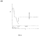
- FIG. 2 illustrates the refractive index profile 200 of the universal optical fiber 100 , in accordance with various embodiments of the present disclosure.
- the refractive index profile 200 illustrates relationship between the refractive index of the universal optical fiber 100 and the radius of the universal optical fiber 100 (as shown in FIG. 1 ).
- the refractive index profile 200 shows change in the relative refractive index of the core 102 , the buffer clad region 104 , the trench region 106 and the cladding 108 with the radius of the universal optical fiber 100 .
- the universal optical fiber 100 has a first ratio.
- the first ratio is ratio of the second radius r 2 of the buffer clad region 104 to the first radius r 1 of the core 102 of the universal optical fiber 100 .
- the first ratio of the universal optical fiber 100 is in range of about 1.5 to 2. In another embodiment of the present disclosure, range of the first ratio of the universal optical fiber 100 may vary. In an example, the first ratio of the universal optical fiber 100 has a value of about 1.7. In another example, the first ratio of the universal optical fiber 100 has a value of about 1.8.
- the universal optical fiber 100 has the mode field diameter. In an example, the mode field diameter is about 9.08 micron at wavelength of 1310 nanometer. In another example, the mode field diameter is about 9.12 micron at wavelength of 1310 nanometer. Further, the universal optical fiber 100 has the zero dispersion wavelength. In an example, the zero dispersion wavelength is about 1308 nanometer. In another example, the zero dispersion wavelength is about 1300 nanometer. In yet another example, the zero dispersion wavelength is about 1313 nanometer. In yet another example, the zero dispersion wavelength is about 1317 nanometer. Furthermore, the universal optical fiber 100 has the dispersion. In an example, the dispersion is about 15 picosecond/(nanometer-kilometer) at wavelength of 1550 nanometer.
- the dispersion is about 17.3 picosecond/(nanometer-kilometer) at wavelength of 1550 nanometer. In yet another example, the dispersion is about 15 picosecond/(nanometer-kilometer) at wavelength of 1550 nanometer. In yet another example, the dispersion is about 17 picosecond/(nanometer-kilometer) at wavelength of 1550 nanometer.
- the universal optical fiber 100 has the cable cut off wavelength.
- the cable cutoff wavelength is about 1206 nanometer.
- the cable cutoff wavelength is about 1230 nanometer.
- the cable cutoff wavelength is about 1240 nanometer.
- the cable cutoff wavelength is about 1210 nanometer.
- the universal optical fiber 100 is associated with macro-bend loss.
- macro-bend loss of the universal optical fiber 100 is about 0.047 decibel per turn corresponding to wavelength of 1550 nanometer at bending radius of 7.5 millimeter.
- macro-bend loss of the universal optical fiber 100 is about 0.121 decibel per turn corresponding to wavelength of 1550 nanometer at bending radius of 7.5 millimeter.
- macro-bend loss of the universal optical fiber 100 is about 0.168 decibel per turn corresponding to wavelength of 1550 nanometer at bending radius of 7.5 millimeter. In yet another example, macro-bend loss of the universal optical fiber 100 is about 0.25 decibel per turn corresponding to wavelength of 1550 nanometer at bending radius of 7.5 millimeter.
- macro-bend loss of the universal optical fiber 100 is about 0.107 decibel per turn corresponding to wavelength of 1625 nanometer at bending radius of 7.5 millimeter. In another example, macro-bend loss of the universal optical fiber 100 is about 0.26 decibel per turn corresponding to wavelength of 1625 nanometer at bending radius of 7.5 millimeter. In yet another example, macro-bend loss of the universal optical fiber 100 is about 0.53 decibel per turn corresponding to wavelength of 1625 nanometer at bending radius of 7.5 millimeter. In yet another example, macro-bend loss of the universal optical fiber 100 is about 0.363 decibel per turn corresponding to wavelength of 1625 nanometer at bending radius of 7.5 millimeter.
- macro-bend loss of the universal optical fiber 100 is about 0.013 decibel per turn corresponding to wavelength of 1550 nanometer at bending radius of 10 millimeter. In another example, macro-bend loss of the universal optical fiber 100 is about 0.031 decibel per turn corresponding to wavelength of 1550 nanometer at bending radius of 10 millimeter. In yet another example, macro-bend loss of the universal optical fiber 100 is about 0.047 decibel per turn corresponding to wavelength of 1550 nanometer at bending radius of 10 millimeter. In yet another example, macro-bend loss of the universal optical fiber 100 is about 0.035 decibel per turn corresponding to wavelength of 1550 nanometer at bending radius of 10 millimeter.
- macro-bend loss of the universal optical fiber 100 is about 0.035 decibel per turn corresponding to wavelength of 1625 nanometer at bending radius of 10 millimeter. In another example, macro-bend loss of the universal optical fiber 100 is about 0.086 decibel per turn corresponding to wavelength of 1625 nanometer at bending radius of 10 millimeter. In yet another example, macro-bend loss of the universal optical fiber 100 is about 0.139 decibel per turn corresponding to wavelength of 1625 nanometer at bending radius of 10 millimeter. In yet another example, macro-bend loss of the universal optical fiber 100 is about 0.103 decibel per turn corresponding to wavelength of 1625 nanometer at bending radius of 10 millimeter.
- macro-bend loss of the universal optical fiber 100 is about 0.007 decibel per 10 turn corresponding to wavelength of 1550 nanometer at bending radius of 15 millimeter. In another example, macro-bend loss of the universal optical fiber 100 is about 0.015 decibel per 10 turn corresponding to wavelength of 1550 nanometer at bending radius of 15 millimeter. In yet another example, macro-bend loss of the universal optical fiber 100 is about 0.016 decibel per 10 turn corresponding to wavelength of 1550 nanometer at bending radius of 15 millimeter. In yet another example, macro-bend loss of the universal optical fiber 100 is about 0.013 decibel per 10 turn corresponding to wavelength of 1550 nanometer at bending radius of 15 millimeter.
- macro-bend loss of the universal optical fiber 100 is about 0.034 decibel per 10 turn corresponding to wavelength of 1625 nanometer at bending radius of 15 millimeter. In another example, macro-bend loss of the universal optical fiber 100 is about 0.069 decibel per 10 turn corresponding to wavelength of 1625 nanometer at bending radius of 15 millimeter. In yet another example, macro-bend loss of the universal optical fiber 100 is about 0.076 decibel per 10 turn corresponding to wavelength of 1625 nanometer at bending radius of 15 millimeter. In yet another example, macro-bend loss of the universal optical fiber 100 is about 0.062 decibel per 10 turn corresponding to wavelength of 1625 nanometer at bending radius of 15 millimeter.
- the present disclosure provides numerous advantages over the prior art.
- the present disclosure provides the universal optical fiber with bend insensitiveness.
- the present disclosure provides an optical fiber of G652D category with the bend performance in compliance with G657 category fibers.
- the present disclosure provides the optical fiber that can be used in FTTX and long haul and access networks.
- the universal optical fiber has large mode field diameter and effective area.
- the universal optical fiber has improved macro-bend performance.
- the universal optical fiber has low non-linear effects as compared to the ITUT G657A2 category.
Landscapes
- Physics & Mathematics (AREA)
- General Physics & Mathematics (AREA)
- Optics & Photonics (AREA)
- Lasers (AREA)
- Manufacture, Treatment Of Glass Fibers (AREA)
- Optical Modulation, Optical Deflection, Nonlinear Optics, Optical Demodulation, Optical Logic Elements (AREA)
Abstract
Description
- The present disclosure relates to the field of optical fiber transmission. More particularly, the present disclosure relates to a bend insensitive universal optical fiber. This application is based on, and claims priority from an Indian Application Number
201921023863 filed on 17th June 2019 - With the advancement of science and technology, various modern technologies are being employed for communication purposes. One of the most important modern communication technologies is optical fiber communication technology using a variety of optical fibers. Optical fiber is used to transmit information as light pulses from one end to another. One such type of optical fiber is a single mode optical fiber. The single mode optical fiber is used in FTTx and long haul communication. The telecommunication industry is continuously striving for designs to achieve high data rate capacity and low losses. The ongoing research suggests that the single mode optical fiber of G657 and G652D category are used for FTTx and long-haul applications. The single mode optical fiber of G652D and G657 categories faces major challenges in FTTx and long haul communication respectively. G652D fibers faces major challenges in FTTx application due to good macro bend losses and G657 category fibers face major challenges in long haul applications due to high nonlinear effects as a result of low MFD. Also Low MFD in G657A2 in long haul communication results in a power penalty more than 1.5 decibel as compared to G652D.
- In light of the above stated discussion, there is a need for a single mode optical fiber that overcomes the above sited drawbacks to use for FTTx as well as long haul and access networks.
- A primary object of the present disclosure is to provide a universal optical fiber with bend insensitivity.
- Another object of the present disclosure is to provide the universal optical fiber with good macro-bend performances.
- Yet another object of the present disclosure is to provide the universal optical fiber with large mode field diameter.
- Yet another object of the present disclosure is to provide the universal optical fiber with large effective area.
- In an aspect of the present disclosure, the present disclosure provides a universal optical fiber. The universal optical fiber includes a core. In addition, the universal optical fiber includes a cladding. Further, the core is defined along a central longitudinal axis of the universal optical fiber. In addition, the core has a first radius r1. Further, the cladding is defined by a third radius r3 and a fourth radius r4 of the universal optical fiber. Furthermore, the universal optical fiber has a mode field diameter. The mode field diameter of the universal optical fiber is in range of about 8.7 micrometer to 9.5 micrometer. Moreover, the universal optical fiber has at least one macro-bend loss up to 0.5 decibel per turn corresponding to wavelength of 1550 nanometer at bending radius of 7.5 millimeter, macro-bend loss up to 1.0 decibel per turn corresponding to wavelength of 1625 nanometer at bending radius of 7.5 millimeter, macro-bend loss up to 0.1 decibel per turn corresponding to wavelength of 1550 nanometer at bending radius of 10 millimeter, macro-bend loss up to 0.2 decibel per turn corresponding to wavelength of 1625 nanometer at bending radius of 10 millimeter, macro-bend loss up to 0.03 decibel per 10 turn corresponding to wavelength of 1550 nanometer at bending radius of 15 millimeter and macro-bend loss up to 0.1 decibel per 10 turn corresponding to wavelength of 1625 nanometer at bending radius of 15 millimeter.
- In an embodiment of the present disclosure, the universal optical fiber includes a trench region. In addition, the trench region is defined by a second radius r2 and the third radius r3. Further, the trench region has a curve parameter αtrench in range of about 1.5 to 2.
- In an embodiment of the present disclosure, the core has a curve parameter α.
- In an embodiment of the present disclosure, the universal optical fiber includes a buffer clad region. In addition, the buffer clad region is defined by the second radius r2 and the first radius r1. Further, a first ratio of r2/r1 is in range of about 1.5 to 2.
- In an embodiment of the present disclosure, the universal optical fiber has at least one of a dispersion of up to 18 picosecond/(nanometer-kilometer) at wavelength of 1550 nanometer. In addition, the universal optical fiber has a zero dispersion wavelength in range of about 1300 nanometer to 1324 nanometer. Further, the universal optical fiber has a cable cut off wavelength of up to 1260 nanometer.
- In an embodiment of the present disclosure, the universal optical fiber has the core. The core has a first relative refractive index Δ1 in range of about 0.35 to 0.40. Further, the core has the first radius r1 in range of about 4.8 micron to 5.5 micron. In addition, the core has a curve parameter α in range of about 2.5 to 7.
- In an embodiment of the present disclosure, the universal optical fiber has a buffer clad region. The buffer clad region has a second relative refractive index Δ2 in range of about 0 to 0.04. Further, the buffer clad region has radius r2 in range of about 7.2 micron to 11 micron.
- In an embodiment of the present disclosure, the universal optical fiber has a trench region. In addition, the trench region has a third relative refractive index Δ3 in range of about -0.25 to -0.30. In addition, the trench region has the third radius r3 in range of about 15 micron to 20 micron.
- In an embodiment of the present disclosure, the cladding has a fourth relative refractive index Δ4. The fourth relative refractive index Δ4 is zero. Furthermore, the cladding (108) has the fourth radius r4 of about 62.5 micron.
- In an embodiment of the present disclosure, the buffer clad region has a second relative refractive index Δ2 in range of about 0 to 0.04.
- In another aspect of the present disclosure, the present disclosure provides a universal optical fiber. The universal optical fiber includes a core. In addition, the universal optical fiber includes a cladding. Further, the core is defined along a central longitudinal axis of the universal optical fiber. In addition, the core has a first radius r1. Further, the cladding is defined by a third radius r3 and a fourth radius r4 of the universal optical fiber. Furthermore, the universal optical fiber includes a trench region. In addition, the trench region is defined by a second radius r2 and the third radius r3. In addition, the trench region concentrically surrounds a buffer clad region. Further, the trench region has a curve parameter αtrench.
- In an embodiment of the present disclosure, the buffer clad region of the universal optical fiber concentrically surrounds the core of the universal optical fiber. In addition, the cladding of the universal optical fiber concentrically surrounds the trench region of the universal optical fiber. Further, the second relative refractive index Δ2 of the buffer clad region is in range of about 0 to 0.04. Furthermore, the fourth relative refractive index Δ4 of the cladding is zero.
- In an embodiment of the present disclosure, the universal optical fiber has a mode field diameter. The mode field diameter of the universal optical fiber is in range of about 8.7 micrometer to 9.5 micrometer. The universal optical fiber (100) has at least one of macro-bend loss up to 0.5 decibel per turn corresponding to wavelength of 1550 nanometer at bending radius of 7.5 millimeter, macro-bend loss up to 1.0 decibel per turn corresponding to wavelength of 1625 nanometer at bending radius of 7.5 millimeter, macro-bend loss up to 0.1 decibel per turn corresponding to wavelength of 1550 nanometer at bending radius of 10 millimeter, macro-bend loss up to 0.2 decibel per turn corresponding to wavelength of 1625 nanometer at bending radius of 10 millimeter, macro-bend loss up to 0.03 decibel per 10 turn corresponding to wavelength of 1550 nanometer at bending radius of 15 millimeter and macro-bend loss up to 0.1 decibel per 10 turn corresponding to wavelength of 1625 nanometer at bending radius of 15 millimeter.
- In an embodiment of the present disclosure, the universal optical fiber has the core. The core has a first relative refractive index Δ1. In addition, the first relative refractive index Δ1 is in range of about 0.35 to 0.40. Further, the core has the first radius r1. The first radius r1 is in range of about 4.8 micron to 5.5 micron. In addition, the core has a curve parameter α in range of about 2.5 to 7. Further, the universal optical fiber has the buffer clad region. The buffer clad region has a second relative refractive index Δ2. In addition, the second relative refractive index Δ2 of buffer clad region is in range of about 0 to 0.04. Further, the buffer clad region has radius r2. Furthermore, the second radius r2 is in range of about 7.2 micron to 11 micron. Furthermore, the universal optical fiber has the trench region. In addition, the trench region has a third relative refractive index Δ3. The third relative refractive index Δ3 is in range of about -0.25 to -0.30. In addition, the trench region has the third radius r3. Further, the third radius r3 is in range of about 15 micron to 20 micron. Moreover, the universal optical fiber has the cladding. In addition, the cladding has a fourth relative refractive index Δ4. Further, the fourth relative refractive index is zero. Furthermore, the cladding has the fourth radius r4. Moreover, the fourth radius r4 is about 62.5 micron.
- In an embodiment of the present disclosure, the universal optical fiber has a first ratio. In addition, the first ratio is a ratio of second radius r2 of the buffer clad region and the first radius r1 of the core of the universal optical fiber. Further, the first radius is in range of about 1.5 to 2.
- In an aspect of the present disclosure, the present disclosure provides a universal optical fiber. The universal optical fiber includes a core. In addition, the universal optical fiber includes a cladding. Further, the core is defined along a central longitudinal axis of the universal optical fiber. In addition, the core has a first radius r1. Further, the cladding is defined by a third radius r3 and a fourth radius r4 of the universal optical fiber. Furthermore, the universal optical fiber has a mode field diameter. The mode field diameter of the universal optical fiber is in range of about 8.7 micrometer to 9.5 micrometer. Moreover, the universal optical fiber has at least one macro-bend loss up to 0.5 decibel per turn corresponding to wavelength of 1550 nanometer at bending radius of 7.5 millimeter, macro-bend loss up to 1.0 decibel per turn corresponding to wavelength of 1625 nanometer at bending radius of 7.5 millimeter, macro-bend loss up to 0.1 decibel per turn corresponding to wavelength of 1550 nanometer at bending radius of 10 millimeter, macro-bend loss up to 0.2 decibel per turn corresponding to wavelength of 1625 nanometer at bending radius of 10 millimeter, macro-bend loss up to 0.03 decibel per 10 turn corresponding to wavelength of 1550 nanometer at bending radius of 15 millimeter and macro-bend loss up to 0.1 decibel per 10 turn corresponding to wavelength of 1625 nanometer at bending radius of 15 millimeter.
- Having thus described the disclosure in general terms, reference will now be made to the accompanying figures, wherein:
-
FIG. 1 illustrates a cross-sectional view of a universal optical fiber, in accordance with various embodiments of the present disclosure; and -
FIG. 2 illustrates a refractive index profile of the universal optical fiber, in accordance with various embodiments of the present disclosure. - It should be noted that the accompanying figures are intended to present illustrations of exemplary embodiments of the present disclosure. These figures are not intended to limit the scope of the present disclosure. It should also be noted that accompanying figures are not necessarily drawn to scale.
- Reference will now be made in detail to selected embodiments of the present disclosure in conjunction with accompanying figures. The embodiments described herein are not intended to limit the scope of the disclosure, and the present disclosure should not be construed as limited to the embodiments described. This disclosure may be embodied in different forms without departing from the scope and spirit of the disclosure. It should be understood that the accompanying figures are intended and provided to illustrate embodiments of the disclosure described below and are not necessarily drawn to scale. In the drawings, like numbers refer to like elements throughout, and thicknesses and dimensions of some components may be exaggerated for providing better clarity and ease of understanding.
- It should be noted that the terms "first", "second", and the like, herein do not denote any order, ranking, quantity, or importance, but rather are used to distinguish one element from another. Further, the terms "a" and "an" herein do not denote a limitation of quantity, but rather denote the presence of at least one of the referenced item.
-
FIG. 1 illustrates a cross-sectional view of a universaloptical fiber 100, in accordance with various embodiments of the present disclosure. In general, optical fiber is a thin strand of glass or plastic capable of transmitting optical signals. In an embodiment of the present disclosure, the universaloptical fiber 100 is configured to transmit information over long distances with low non-linear effects as compared to G657A2 and good macro-bend performance. - The universal
optical fiber 100 includes acore 102, acladding 108, a buffer cladregion 104 and atrench region 106. In general, core is an inner part of an optical fiber and cladding is an outer part of the optical fiber. In an embodiment of the present disclosure, thecore 102 is defined along a centrallongitudinal axis 110 of the universaloptical fiber 100. The centrallongitudinal axis 110 is an imaginary axis. - Further, the
core 102, thecladding 108, the buffer cladregion 104 and thetrench region 106 of the universaloptical fiber 100 are associated with a refractive index profile. In general, the refractive index profile is maintained as per required level based on concentration of chemicals used for manufacturing of an optical fiber. In addition, the chemicals used for manufacturing of the optical fiber include one or more materials and one or more dopants. Further, the one or more materials and the one or more dopants are deposited over surface of initial material with facilitation of flame hydrolysis. Furthermore, the initial material is a substrate rod or a tube. - In an embodiment of the present disclosure, the refractive index profile determines relationship between a refractive index of the universal
optical fiber 100 and a radius of the universaloptical fiber 100. In addition, the radius of the universaloptical fiber 100 corresponds to a first radius r1, a second radius r2, a third radius r3 and a fourth radius r4. In an embodiment of the present disclosure, manufacturing of the universaloptical fiber 100 is carried out after manufacturing of a preform. Further, the refractive index profile of the universaloptical fiber 100 is determined during manufacturing of the preform of the universaloptical fiber 100. - In an embodiment of the present disclosure, the
core 102 of the universaloptical fiber 100 has a first relative refractive index Δ1. In addition, thecore 102 has maximum refractive index nmax. Further, thecore 102 has a curve parameter α (alpha). Furthermore, thecore 102 of the universaloptical fiber 100 has the first radius r1. In an embodiment of the present disclosure, the first radius r1 is in range of about 4.8 micron to 5.5 micron. In another embodiment of the present disclosure, range of the first radius r1 of thecore 102 may vary. In an example, thecore 102 has a first radius of about 4.92 micron. In another example, the core has the first radius of about 4.95 micron. In yet another example, the first radius has a value of about 5.3 micron. In an embodiment of the present disclosure, thecore 102 has the first relative refractive index Δ1 in range of about 0.35 to 0.40. In another embodiment of the present disclosure, range of the first relative refractive index Δ1 may vary. In an example, the first relative refractive index Δ1 has a value of 0.36. In another example, the first relative refractive index Δ1 has a value of 0.38. In an embodiment of the present disclosure, the curve parameter alpha α is in range of about 3 to 6. In another embodiment of the present disclosure, range of the curve parameter alpha α may vary. In an example, the value of alpha α is 3. In another example the value of alpha α is 5. In yet another example, the value of alpha α is 6. - The expression used for calculating the relative refractive index is produced below:

- wherein, nclad : refractive index of the pure silica;
- ni : refractive index of the ith layer;
- Δi: the relative refractive index of ith layer.
- In an embodiment of the present disclosure, the refractive index profile changes between the second radius r2 and the fourth radius r4 of the universal
optical fiber 100. Further, the relative refractive index of thecore 102, thecladding 108, the buffer cladregion 104 and thetrench region 106 has a pre-defined value. Furthermore, the radius of thecore 102, thecladding 108, the buffer cladregion 104 and thetrench region 106 has a pre-defined value. In an embodiment of the present disclosure, the pre-defined values of the relative refractive index is set to obtain good macro-bend performance and reduce non-linear effects as compared to G657A2. - In an embodiment of the present disclosure, the buffer clad
region 104 is defined by the first radius r1 and the second radius r2 from the centrallongitudinal axis 110 of the universaloptical fiber 100. The buffer cladregion 104 has a second relative refractive index Δ2. Further, thetrench region 106 is defined by the second radius r2 and the third radius r3 from the centrallongitudinal axis 110 of the universaloptical fiber 100. Thetrench region 106 has a third relative refractive index Δ3. Furthermore, thecladding 108 is defined by the third radius r3 and the fourth radius r4 Moreover, thecladding 108 has a fourth relative refractive index of Δ4. - In an embodiment of the present disclosure, the buffer clad
region 104 of the universaloptical fiber 100 has the second radius r2 in range of about 7.2 micron to 11 micron. In another embodiment of the present disclosure, range of the second radius r2 may vary. In an example, the the second radius r2 has a value of 8.364 micron. In another example, the second radius r2 has a value of 8.91 micron. In yet another example, the second radius r2 has a value of 9.01 micron. In an embodiment of the present disclosure, the buffer cladregion 104 of the universaloptical fiber 100 has the second relative refractive index Δ2 is in range of about 0 to 0.04. In another embodiment of the present disclosure, the second relative refractive index Δ2 of the buffer cladregion 104 of the universaloptical fiber 100 may vary. In an example, the second relative refractive index Δ2 has a value of 0. In another example, the second relative refractive index Δ2 has a value of 0.02. In yet another example, the second relative refractive index Δ2 has a value of 0.04. - In an embodiment of the present disclosure, the
trench region 106 of the universaloptical fiber 100 has the third radius r3 in range of about 15 micron to 20 micron. In another embodiment of the present disclosure, range of the third radius r3 may vary. In an example, the third radius r3 has a value of 15.5. In another example, the third radius r3 has a value 17. In yet another example, the third radius r3 has value of about 19. In an embodiment of the present disclosure, thetrench region 106 of the universaloptical fiber 100 has the third relative refractive index Δ3 is in range of about -0.25 to -0.30. In another embodiment of the present disclosure, range of the third relative refractive index Δ3 may vary. In an example, the third relative refractive index Δ3 has a value of about -0.29. In another example, the third relative refractive index Δ3 has a value of about -0.26. In yet another example, the third relative refractive index Δ3 has a value of about -0.28. In an embodiment of the present disclosure, thetrench region 106 includes a curve parameter αtrench about 1.5. In another embodiment of the present disclosure, value of the curve parameter αtrench may vary. In an example, the curve parameter αtrench has a value of 1.9. In another example, the curve parameter αtrench has a value of about 1.6. In yet another example, the curve parameter αtrench has a value of about 1.7. - In an embodiment of the present disclosure, the
cladding 108 of the universaloptical fiber 100 has the fourth radius r4 of about 62.5 micron. In another embodiment of the present disclosure, value of the fourth radius r4 may vary. In an embodiment of the present disclosure, thecladding 108 has the fourth relative refractive index Δ4 of zero. In another embodiment of the present disclosure, the fourth relative refractive index Δ4 of thecladding 108 of the universaloptical fiber 100 may vary. - In an embodiment of the present disclosure, the
core 102 of the universaloptical fiber 100 has maximum refractive index nmax. In addition, the buffer cladregion 104 has refractive index of pure silica nclad. Further, minimum refractive index of thetrench region 106 is ntrench. Furthermore, expressions used to determine refractive index is given by below:

- In an embodiment of the present disclosure, the refractive index profile of the universal
optical fiber 100 low non-linear effects as compared to G657A2 and good macro-bend performance. Further, the universaloptical fiber 100 has large mode field diameter and large effective area. - In an embodiment of the present disclosure, the universal
optical fiber 100 has the mode field diameter in range of about 8.7 micron to 9.5 micron at wavelength of 1310 nanometer. In another embodiment of the present disclosure, range of the mode field diameter of the universaloptical fiber 100 may vary. In general, mode field diameter defines a section or area of optical fiber in which the optical signals travel. In an embodiment of the present disclosure, thecladding 108 of the universaloptical fiber 100 has a diameter in range of about 124.3 micron to 125.7 micron. In another embodiment of the present disclosure, the diameter of thecladding 108 of the universaloptical fiber 100 may vary. - In an embodiment of the present disclosure, the universal
optical fiber 100 has a cable cut off wavelength of up to 1260 nanometer. In another embodiment of the present disclosure, the cable cut off wavelength of the universaloptical fiber 100 may vary. In an embodiment of the present disclosure, the universaloptical fiber 100 has a zero dispersion wavelength in range of about 1300 nanometer to 1324 nanometer. In another embodiment of the present disclosure, range of the zero dispersion wavelength of the universaloptical fiber 100 may vary. - In an embodiment of the present disclosure, the universal
optical fiber 100 has a dispersion of up to 18 picosecond/(nanometer-kilometer). In another embodiment of the present disclosure, the dispersion of the universaloptical fiber 100 may vary. - The universal
optical fiber 100 has macro-bend loss in complaint to the ITUT G657.A2. In general, bending loss is a loss that occurs when optical fiber is bent. In addition, bending loss includes macro-bend loss and a micro-bend loss. Moreover, the universaloptical fiber 100 has at least one macro-bend loss up to 0.5 decibel per turn corresponding to wavelength of 1550 nanometer at bending radius of 7.5 millimeter, macro-bend loss up to 1.0 decibel per turn corresponding to wavelength of 1625 nanometer at bending radius of 7.5 millimeter, macro-bend loss up to 0.1 decibel per turn corresponding to wavelength of 1550 nanometer at bending radius of 10 millimeter, macro-bend loss up to 0.2 decibel per turn corresponding to wavelength of 1625 nanometer at bending radius of 10 millimeter, macro-bend loss up to 0.03 decibel per 10 turn corresponding to wavelength of 1550 nanometer at bending radius of 15 millimeter and macro-bend loss up to 0.1 decibel per 10 turn corresponding to wavelength of 1625 nanometer at bending radius of 15 millimeter. - In general, bending radius is a minimum radius of the inner curvature formed on bending optical fiber.
-
FIG. 2 illustrates therefractive index profile 200 of the universaloptical fiber 100, in accordance with various embodiments of the present disclosure. Therefractive index profile 200 illustrates relationship between the refractive index of the universaloptical fiber 100 and the radius of the universal optical fiber 100 (as shown inFIG. 1 ). In an embodiment of the present disclosure, therefractive index profile 200 shows change in the relative refractive index of thecore 102, the buffer cladregion 104, thetrench region 106 and thecladding 108 with the radius of the universaloptical fiber 100. - In an embodiment of the present disclosure, the universal
optical fiber 100 has a first ratio. In addition the first ratio is ratio of the second radius r2 of the buffer cladregion 104 to the first radius r1 of thecore 102 of the universaloptical fiber 100. In an embodiment of the present disclosure, the first ratio of the universaloptical fiber 100 is in range of about 1.5 to 2. In another embodiment of the present disclosure, range of the first ratio of the universaloptical fiber 100 may vary. In an example, the first ratio of the universaloptical fiber 100 has a value of about 1.7. In another example, the first ratio of the universaloptical fiber 100 has a value of about 1.8. - In addition, the universal
optical fiber 100 has the mode field diameter. In an example, the mode field diameter is about 9.08 micron at wavelength of 1310 nanometer. In another example, the mode field diameter is about 9.12 micron at wavelength of 1310 nanometer. Further, the universaloptical fiber 100 has the zero dispersion wavelength. In an example, the zero dispersion wavelength is about 1308 nanometer. In another example, the zero dispersion wavelength is about 1300 nanometer. In yet another example, the zero dispersion wavelength is about 1313 nanometer. In yet another example, the zero dispersion wavelength is about 1317 nanometer. Furthermore, the universaloptical fiber 100 has the dispersion. In an example, the dispersion is about 15 picosecond/(nanometer-kilometer) at wavelength of 1550 nanometer. In another example, the dispersion is about 17.3 picosecond/(nanometer-kilometer) at wavelength of 1550 nanometer. In yet another example, the dispersion is about 15 picosecond/(nanometer-kilometer) at wavelength of 1550 nanometer. In yet another example, the dispersion is about 17 picosecond/(nanometer-kilometer) at wavelength of 1550 nanometer. - Moreover, the universal
optical fiber 100 has the cable cut off wavelength. In an example, the cable cutoff wavelength is about 1206 nanometer. In another example, the cable cutoff wavelength is about 1230 nanometer. In yet another example, the cable cutoff wavelength is about 1240 nanometer. In yet another example, the cable cutoff wavelength is about 1210 nanometer. Also, the universaloptical fiber 100 is associated with macro-bend loss. In an example, macro-bend loss of the universaloptical fiber 100 is about 0.047 decibel per turn corresponding to wavelength of 1550 nanometer at bending radius of 7.5 millimeter. In another example, macro-bend loss of the universaloptical fiber 100 is about 0.121 decibel per turn corresponding to wavelength of 1550 nanometer at bending radius of 7.5 millimeter. In yet another example, macro-bend loss of the universaloptical fiber 100 is about 0.168 decibel per turn corresponding to wavelength of 1550 nanometer at bending radius of 7.5 millimeter. In yet another example, macro-bend loss of the universaloptical fiber 100 is about 0.25 decibel per turn corresponding to wavelength of 1550 nanometer at bending radius of 7.5 millimeter. - In an example, macro-bend loss of the universal
optical fiber 100 is about 0.107 decibel per turn corresponding to wavelength of 1625 nanometer at bending radius of 7.5 millimeter. In another example, macro-bend loss of the universaloptical fiber 100 is about 0.26 decibel per turn corresponding to wavelength of 1625 nanometer at bending radius of 7.5 millimeter. In yet another example, macro-bend loss of the universaloptical fiber 100 is about 0.53 decibel per turn corresponding to wavelength of 1625 nanometer at bending radius of 7.5 millimeter. In yet another example, macro-bend loss of the universaloptical fiber 100 is about 0.363 decibel per turn corresponding to wavelength of 1625 nanometer at bending radius of 7.5 millimeter. - In an example, macro-bend loss of the universal
optical fiber 100 is about 0.013 decibel per turn corresponding to wavelength of 1550 nanometer at bending radius of 10 millimeter. In another example, macro-bend loss of the universaloptical fiber 100 is about 0.031 decibel per turn corresponding to wavelength of 1550 nanometer at bending radius of 10 millimeter. In yet another example, macro-bend loss of the universaloptical fiber 100 is about 0.047 decibel per turn corresponding to wavelength of 1550 nanometer at bending radius of 10 millimeter. In yet another example, macro-bend loss of the universaloptical fiber 100 is about 0.035 decibel per turn corresponding to wavelength of 1550 nanometer at bending radius of 10 millimeter. - In an example, macro-bend loss of the universal
optical fiber 100 is about 0.035 decibel per turn corresponding to wavelength of 1625 nanometer at bending radius of 10 millimeter. In another example, macro-bend loss of the universaloptical fiber 100 is about 0.086 decibel per turn corresponding to wavelength of 1625 nanometer at bending radius of 10 millimeter. In yet another example, macro-bend loss of the universaloptical fiber 100 is about 0.139 decibel per turn corresponding to wavelength of 1625 nanometer at bending radius of 10 millimeter. In yet another example, macro-bend loss of the universaloptical fiber 100 is about 0.103 decibel per turn corresponding to wavelength of 1625 nanometer at bending radius of 10 millimeter. - In an example, macro-bend loss of the universal
optical fiber 100 is about 0.007 decibel per 10 turn corresponding to wavelength of 1550 nanometer at bending radius of 15 millimeter. In another example, macro-bend loss of the universaloptical fiber 100 is about 0.015 decibel per 10 turn corresponding to wavelength of 1550 nanometer at bending radius of 15 millimeter. In yet another example, macro-bend loss of the universaloptical fiber 100 is about 0.016 decibel per 10 turn corresponding to wavelength of 1550 nanometer at bending radius of 15 millimeter. In yet another example, macro-bend loss of the universaloptical fiber 100 is about 0.013 decibel per 10 turn corresponding to wavelength of 1550 nanometer at bending radius of 15 millimeter. - In an example, macro-bend loss of the universal
optical fiber 100 is about 0.034 decibel per 10 turn corresponding to wavelength of 1625 nanometer at bending radius of 15 millimeter. In another example, macro-bend loss of the universaloptical fiber 100 is about 0.069 decibel per 10 turn corresponding to wavelength of 1625 nanometer at bending radius of 15 millimeter. In yet another example, macro-bend loss of the universaloptical fiber 100 is about 0.076 decibel per 10 turn corresponding to wavelength of 1625 nanometer at bending radius of 15 millimeter. In yet another example, macro-bend loss of the universaloptical fiber 100 is about 0.062 decibel per 10 turn corresponding to wavelength of 1625 nanometer at bending radius of 15 millimeter. - The present disclosure provides numerous advantages over the prior art. The present disclosure provides the universal optical fiber with bend insensitiveness. In addition, the present disclosure provides an optical fiber of G652D category with the bend performance in compliance with G657 category fibers. Further, the present disclosure provides the optical fiber that can be used in FTTX and long haul and access networks. Further, the universal optical fiber has large mode field diameter and effective area. Further, the universal optical fiber has improved macro-bend performance. Furthermore, the universal optical fiber has low non-linear effects as compared to the ITUT G657A2 category.
- The foregoing descriptions of specific embodiments of the present technology have been presented for purposes of illustration and description. They are not intended to be exhaustive or to limit the present technology to the precise forms disclosed, and obviously many modifications and variations are possible in light of the above teaching. The embodiments were chosen and described in order to best explain the principles of the present technology and its practical application, to thereby enable others skilled in the art to best utilize the present technology and various embodiments with various modifications as are suited to the particular use contemplated. It is understood that various omissions and substitutions of equivalents are contemplated as circumstance may suggest or render expedient, but such are intended to cover the application or implementation without departing from the spirit or scope of the claims of the present technology.
Claims (15)
- A universal optical fiber (100) comprising:a core (102), wherein the core (102) is defined along a central longitudinal axis (110) of the universal optical fiber (100), wherein the core (102) has a first radius r1; anda cladding (108), wherein the cladding (108) is defined by a third radius r3 and a fourth radius r4 of the universal optical fiber (100),wherein the universal optical fiber (100) has a mode field diameter in range of about 8.7 micrometer to 9.5 micrometer,wherein the universal optical fiber (100) has at least one of macro-bend loss up to 0.5 decibel per turn corresponding to wavelength of 1550 nanometer at bending radius of 7.5 millimeter, macro-bend loss up to 1.0 decibel per turn corresponding to wavelength of 1625 nanometer at bending radius of 7.5 millimeter, macro-bend loss up to 0.1 decibel per turn corresponding to wavelength of 1550 nanometer at bending radius of 10 millimeter, macro-bend loss up to 0.2 decibel per turn corresponding to wavelength of 1625 nanometer at bending radius of 10 millimeter and macro-bend loss up to 0.03 decibel per 10 turn corresponding to wavelength of 1550 nanometer at bending radius of 15 millimeter, and macro-bend loss is up to 0.1 decibel per 10 turn corresponding to wavelength of 1625 nanometer at bending radius of 15 millimeter.
- The universal optical fiber (100) as claimed in claim 1, further comprising a trench region (106), wherein the trench region (106) is defined by a second radius r2 and the third radius r3, wherein the trench region (106) has a curve parameter αtrench, wherein the curve parameter αtrench is in range of about 1.5 to 2.
- The universal optical fiber (100) as claimed in claim 1, wherein the core (102) has a curve parameter α.
- The universal optical fiber (100) as claimed in claim 1, further comprising a buffer clad region (104), wherein the buffer clad region (104) is defined by a second radius r2 and the first radius r1, wherein a first ratio of r2/r1 is in range of 1.5 to 2.
- The universal optical fiber (100) as claimed in claim 1, wherein the universal optical fiber (100) has at least one of a dispersion of up to 18 picosecond/(nanometer-kilometer) at wavelength of 1550 nanometer, a zero dispersion wavelength in a range of about 1300 nanometer to 1324 nanometer and a cable cut off wavelength of up to 1260 nanometer.
- The universal optical fiber (100) as claimed in claim 1, wherein the core (102) has at least one of:a. a first relative refractive index Δ1 in range of about 0.35 to 0.40;b. the first radius r1 in range of about 4.8 micron to 5.5 micron; andc. a curve parameter α in range of about 2.5 to 7.
- The universal optical fiber (100) as claimed in claim 1, further comprising a buffer clad region (104), wherein the buffer clad region (104) has at least one of:a. a second relative refractive index Δ2 in range of about 0 to 0.04; andb. a second radius r2 in range of about 7.2 micron to 11 micron.
- The universal optical fiber (100) as claimed in claim 1, further comprising a trench region (106), wherein the trench region (106) has at least one of:a. a third relative refractive index Δ3 in range of about -0.25 to -0.30; andb. the third radius r3 in range of about 15 micron to 20 micron.
- The universal optical fiber (100) as claimed in claim 1, wherein the cladding (108) has at least one of:a. a fourth relative refractive index Δ4, wherein the fourth relative refractive index is zero; andb. the fourth radius r4, wherein the fourth radius r4 is about 62.5 micron.
- The universal optical fiber (100) as claimed in claim 1, further comprising a buffer clad region (104), wherein the buffer clad region (104) has a second relative refractive index Δ2, wherein the second relative refractive index Δ2 is in range of about 0 to 0.04.
- A universal optical fiber (100) comprising:a core (102), wherein the core (102) is defined along a central longitudinal axis (110) of the universal optical fiber (100), wherein the core (102) has a first radius r1;a cladding (108), wherein the cladding (108) is defined by a third radius r3 and a fourth radius r4 of the universal optical fiber (100); anda trench region (106), wherein the trench region (106) is defined by a second radius r2 and the third radius r3, wherein the trench region (106) concentrically surrounds a buffer clad region (104), wherein the trench region (106) has a curve parameter αtrench.
- The universal optical fiber (100) as claimed in claim 11, wherein the buffer clad region (104) of the universal optical fiber (100) concentrically surrounds the core (102) of the universal optical fiber (100), wherein the cladding (108) of the universal optical fiber (100) concentrically surrounds the trench region (106) of the universal optical fiber (100), wherein the second relative refractive index Δ2 of the buffer clad region (104) is in range of about 0 to 0.04, wherein the fourth relative refractive index Δ4 of the cladding (108) is zero.
- The universal optical fiber (100) as claimed in claim 11, wherein the universal optical fiber (100) has a mode field diameter in range of about 8.7 micrometer to 9.5 micrometer, wherein the universal optical fiber (100) has at least one of macro-bend loss up to 0.5 decibel per turn corresponding to wavelength of 1550 nanometer at bending radius of 7.5 millimeter, macro-bend loss up to 1.0 decibel per turn corresponding to wavelength of 1625 nanometer at bending radius of 7.5 millimeter, macro-bend loss up to 0.1 decibel per turn corresponding to wavelength of 1550 nanometer at bending radius of 10 millimeter, macro-bend loss up to 0.2 decibel per turn corresponding to wavelength of 1625 nanometer at bending radius of 10 millimeter, macro-bend loss of up to 0.03 decibel per 10 turn corresponding to wavelength of 1550 nanometer at bending radius of 15 millimeter, and macro-bend loss up to 0.1 decibel per 10 turn corresponding to wavelength of 1625 nanometer at bending radius of 15 millimeter.
- The universal optical fiber (100) as claimed in claim 11, wherein the universal optical fiber (100) has the core (102), wherein the core (102) has a first relative refractive index Δ1, wherein the first relative refractive index Δ1 is in range of about 0.35 to 0.40, wherein the core (102) has the first radius r1, wherein the first radius r1 is in range of about 4.8 micron to 5.5 micron, wherein the core has a curve parameter α in range of about 2.5 to 7, wherein the universal optical fiber (100) has the buffer clad region (104), wherein the buffer clad region (104) has a second relative refractive index Δ2, wherein the second relative refractive index Δ2 of the buffer clad region (104) is in range of about 0 to 0.04, wherein the buffer clad region (104) has the second radius r2, wherein the second radius r2 is in range of about 7.2 micron to 11 micron, wherein the universal optical fiber (100) has the trench region (106), wherein the trench region (106) has a third relative refractive index Δ3, wherein the third relative refractive index Δ3 is in range of about -0.25 to -0.30, wherein the trench region (106) has the third radius r3, wherein the third radius r3 is in range of about 15 micron to 20 micron, wherein the universal optical fiber (100) has the cladding (108), wherein the cladding (108) has a fourth relative refractive index Δ4, wherein the fourth relative refractive index is zero, wherein the cladding (108) has the fourth radius r4, wherein the fourth radius r4 is about 62.5 micron.
- The universal optical fiber (100) as claimed in claim 11, wherein the universal optical fiber (100) has a first ratio, wherein the first ratio is a ratio of the second radius r2 of the buffer clad region (104) and the first radius r1 of the core (102) of the universal optical fiber (100).
Applications Claiming Priority (1)
| Application Number | Priority Date | Filing Date | Title |
|---|---|---|---|
| IN201921023863 | 2019-06-17 |
Publications (1)
| Publication Number | Publication Date |
|---|---|
| EP3754392A1 true EP3754392A1 (en) | 2020-12-23 |
Family
ID=67544039
Family Applications (1)
| Application Number | Title | Priority Date | Filing Date |
|---|---|---|---|
| EP19189846.9A Pending EP3754392A1 (en) | 2019-06-17 | 2019-08-02 | Universal optical fiber |
Country Status (3)
| Country | Link |
|---|---|
| US (1) | US11714227B2 (en) |
| EP (1) | EP3754392A1 (en) |
| CN (1) | CN112099132A (en) |
Cited By (2)
| Publication number | Priority date | Publication date | Assignee | Title |
|---|---|---|---|---|
| EP3865920A1 (en) * | 2020-02-12 | 2021-08-18 | Sterlite Technologies Limited | Optical fibre having centerline core profile |
| JP2024529448A (en) * | 2021-07-26 | 2024-08-06 | オーエフエス ファイテル,エルエルシー | Optical fiber with triangular trench profile - Patents.com |
Families Citing this family (3)
| Publication number | Priority date | Publication date | Assignee | Title |
|---|---|---|---|---|
| CN112305666A (en) * | 2019-07-29 | 2021-02-02 | 斯特里特技术有限公司 | Cutoff Shift Fiber |
| WO2023038769A1 (en) * | 2021-09-09 | 2023-03-16 | Corning Incorporated | Optical fibers for single mode and few mode vcsel-based optical fiber transmission systems |
| US12353002B2 (en) * | 2022-12-22 | 2025-07-08 | Sterlite Technologies Limited | Optical fiber with improved microbending performance |
Citations (7)
| Publication number | Priority date | Publication date | Assignee | Title |
|---|---|---|---|---|
| US20110058780A1 (en) * | 2009-06-26 | 2011-03-10 | Qingrong Han | Single-mode fiber and production method thereof |
| US20110229101A1 (en) * | 2010-03-17 | 2011-09-22 | Draka Comteq B.V. | Single-Mode Optical Fiber |
| US20120183268A1 (en) * | 2008-05-06 | 2012-07-19 | Draka Comteq B.V. | Single-Mode Optical Fiber Having Reduced Bending Losses |
| US20140185996A1 (en) * | 2012-01-10 | 2014-07-03 | Yangtze Optical Fibre And Cable Joint Stock Limited Company | Bending insensitive single mode optical fiber |
| US20160139333A1 (en) * | 2012-01-10 | 2016-05-19 | Yangtze Optical Fibre And Cable Joint Stock Limited Company | Bending insensitive single-mode optical fiber |
| US20160209585A1 (en) * | 2014-08-01 | 2016-07-21 | Fujikura Ltd. | Optical fiber and manufacturing method thereof |
| US20180120503A1 (en) * | 2016-10-27 | 2018-05-03 | Corning Incorporated | Low bend loss single mode optical fiber |
Family Cites Families (5)
| Publication number | Priority date | Publication date | Assignee | Title |
|---|---|---|---|---|
| US8472770B2 (en) * | 2007-06-15 | 2013-06-25 | Ofs Fitel, Llc | Single mode optical fibers and modular method of making same |
| US10067287B2 (en) * | 2014-09-26 | 2018-09-04 | Fujikura Ltd. | Optical fiber and method of manufacturing the same |
| CN104391351B (en) * | 2014-11-25 | 2017-07-21 | 长飞光纤光缆股份有限公司 | A kind of anti-bending multimode fiber |
| US20180292604A1 (en) * | 2017-04-11 | 2018-10-11 | Ofs Fitel, Llc | Bend-insensitive single-mode optical fiber for fused biconical taper fiber optic coupler |
| CN112305666A (en) * | 2019-07-29 | 2021-02-02 | 斯特里特技术有限公司 | Cutoff Shift Fiber |
-
2019
- 2019-08-01 US US16/528,808 patent/US11714227B2/en active Active
- 2019-08-02 EP EP19189846.9A patent/EP3754392A1/en active Pending
- 2019-09-30 CN CN201910940613.6A patent/CN112099132A/en active Pending
Patent Citations (7)
| Publication number | Priority date | Publication date | Assignee | Title |
|---|---|---|---|---|
| US20120183268A1 (en) * | 2008-05-06 | 2012-07-19 | Draka Comteq B.V. | Single-Mode Optical Fiber Having Reduced Bending Losses |
| US20110058780A1 (en) * | 2009-06-26 | 2011-03-10 | Qingrong Han | Single-mode fiber and production method thereof |
| US20110229101A1 (en) * | 2010-03-17 | 2011-09-22 | Draka Comteq B.V. | Single-Mode Optical Fiber |
| US20140185996A1 (en) * | 2012-01-10 | 2014-07-03 | Yangtze Optical Fibre And Cable Joint Stock Limited Company | Bending insensitive single mode optical fiber |
| US20160139333A1 (en) * | 2012-01-10 | 2016-05-19 | Yangtze Optical Fibre And Cable Joint Stock Limited Company | Bending insensitive single-mode optical fiber |
| US20160209585A1 (en) * | 2014-08-01 | 2016-07-21 | Fujikura Ltd. | Optical fiber and manufacturing method thereof |
| US20180120503A1 (en) * | 2016-10-27 | 2018-05-03 | Corning Incorporated | Low bend loss single mode optical fiber |
Cited By (2)
| Publication number | Priority date | Publication date | Assignee | Title |
|---|---|---|---|---|
| EP3865920A1 (en) * | 2020-02-12 | 2021-08-18 | Sterlite Technologies Limited | Optical fibre having centerline core profile |
| JP2024529448A (en) * | 2021-07-26 | 2024-08-06 | オーエフエス ファイテル,エルエルシー | Optical fiber with triangular trench profile - Patents.com |
Also Published As
| Publication number | Publication date |
|---|---|
| US20210033780A1 (en) | 2021-02-04 |
| US11714227B2 (en) | 2023-08-01 |
| CN112099132A (en) | 2020-12-18 |
Similar Documents
| Publication | Publication Date | Title |
|---|---|---|
| US11714227B2 (en) | Universal optical fiber | |
| EP2503368A1 (en) | Multimode optical fiber with improved bend resistance | |
| US11573368B2 (en) | Universal optical fibre with double trench | |
| EP0789257A1 (en) | Dispersion-shifted fiber | |
| US20040197063A1 (en) | Dispersion shifted fiber having low dispersion slope | |
| CN1268949C (en) | Optical fiber having negative dispersion, negative dispersion slope and large effective area | |
| US11561341B2 (en) | Cutoff shifted optical fibre | |
| US11327222B2 (en) | Cut-off shifted optical fibre with large effective area | |
| EP2253974A1 (en) | Optical fiber | |
| EP3859412B1 (en) | Few mode optical fiber | |
| EP3933467B1 (en) | Optical fibre | |
| US11592616B2 (en) | Universal optical fibre with super Gaussian profile | |
| EP3865920A1 (en) | Optical fibre having centerline core profile | |
| EP4209811A1 (en) | Ultra-low loss optical fibers for long haul communications | |
| EP4418024A1 (en) | Optical fiber with a large effective area | |
| EP4394462A1 (en) | Optical fiber with a fluorine cladding adjacent to the core | |
| EP4485022A1 (en) | Optical fiber cable and optical fiber with reduced diameter | |
| EP4411437A1 (en) | Optical fiber with improved macro-bending and micro-bending performance | |
| EP4390476A1 (en) | Optical fiber with improved micro bending performance | |
| EP4254028A1 (en) | Single mode optical fiber suitable for ribbon applications | |
| EP4485023A1 (en) | Optical fiber and optical fiber cable | |
| US20260043961A1 (en) | Optical Fiber Cable and Optical Fiber with Reduced Diameter | |
| EP4418025A1 (en) | Multicore optical fiber and multicore optical fiber cable | |
| US20260043959A1 (en) | Few-mode optical fiber | |
| US10408996B2 (en) | Non-zero dispersion shifted fiber with low cut off wavelength and large effective area |
Legal Events
| Date | Code | Title | Description |
|---|---|---|---|
| PUAI | Public reference made under article 153(3) epc to a published international application that has entered the european phase |
Free format text: ORIGINAL CODE: 0009012 |
|
| STAA | Information on the status of an ep patent application or granted ep patent |
Free format text: STATUS: THE APPLICATION HAS BEEN PUBLISHED |
|
| AK | Designated contracting states |
Kind code of ref document: A1 Designated state(s): AL AT BE BG CH CY CZ DE DK EE ES FI FR GB GR HR HU IE IS IT LI LT LU LV MC MK MT NL NO PL PT RO RS SE SI SK SM TR |
|
| AX | Request for extension of the european patent |
Extension state: BA ME |
|
| STAA | Information on the status of an ep patent application or granted ep patent |
Free format text: STATUS: REQUEST FOR EXAMINATION WAS MADE |
|
| 17P | Request for examination filed |
Effective date: 20210906 |
|
| RBV | Designated contracting states (corrected) |
Designated state(s): AL AT BE BG CH CY CZ DE DK EE ES FI FR GB GR HR HU IE IS IT LI LT LU LV MC MK MT NL NO PL PT RO RS SE SI SK SM TR |
|
| STAA | Information on the status of an ep patent application or granted ep patent |
Free format text: STATUS: EXAMINATION IS IN PROGRESS |
|
| 17Q | First examination report despatched |
Effective date: 20230703 |