EP3754374A1 - Fish weight measuring apparatus - Google Patents
Fish weight measuring apparatus Download PDFInfo
- Publication number
- EP3754374A1 EP3754374A1 EP19180594.4A EP19180594A EP3754374A1 EP 3754374 A1 EP3754374 A1 EP 3754374A1 EP 19180594 A EP19180594 A EP 19180594A EP 3754374 A1 EP3754374 A1 EP 3754374A1
- Authority
- EP
- European Patent Office
- Prior art keywords
- target
- length
- measuring
- camera
- transducer
- Prior art date
- Legal status (The legal status is an assumption and is not a legal conclusion. Google has not performed a legal analysis and makes no representation as to the accuracy of the status listed.)
- Granted
Links
Images




Classifications
-
- G—PHYSICS
- G01—MEASURING; TESTING
- G01S—RADIO DIRECTION-FINDING; RADIO NAVIGATION; DETERMINING DISTANCE OR VELOCITY BY USE OF RADIO WAVES; LOCATING OR PRESENCE-DETECTING BY USE OF THE REFLECTION OR RERADIATION OF RADIO WAVES; ANALOGOUS ARRANGEMENTS USING OTHER WAVES
- G01S15/00—Systems using the reflection or reradiation of acoustic waves, e.g. sonar systems
- G01S15/88—Sonar systems specially adapted for specific applications
- G01S15/96—Sonar systems specially adapted for specific applications for locating fish
-
- G—PHYSICS
- G01—MEASURING; TESTING
- G01S—RADIO DIRECTION-FINDING; RADIO NAVIGATION; DETERMINING DISTANCE OR VELOCITY BY USE OF RADIO WAVES; LOCATING OR PRESENCE-DETECTING BY USE OF THE REFLECTION OR RERADIATION OF RADIO WAVES; ANALOGOUS ARRANGEMENTS USING OTHER WAVES
- G01S15/00—Systems using the reflection or reradiation of acoustic waves, e.g. sonar systems
- G01S15/86—Combinations of sonar systems with lidar systems; Combinations of sonar systems with systems not using wave reflection
-
- G—PHYSICS
- G01—MEASURING; TESTING
- G01S—RADIO DIRECTION-FINDING; RADIO NAVIGATION; DETERMINING DISTANCE OR VELOCITY BY USE OF RADIO WAVES; LOCATING OR PRESENCE-DETECTING BY USE OF THE REFLECTION OR RERADIATION OF RADIO WAVES; ANALOGOUS ARRANGEMENTS USING OTHER WAVES
- G01S7/00—Details of systems according to groups G01S13/00, G01S15/00, G01S17/00
- G01S7/52—Details of systems according to groups G01S13/00, G01S15/00, G01S17/00 of systems according to group G01S15/00
- G01S7/539—Details of systems according to groups G01S13/00, G01S15/00, G01S17/00 of systems according to group G01S15/00 using analysis of echo signal for target characterisation; Target signature; Target cross-section
Definitions
- the target measuring apparatus includes the target measuring system selects the target that is close to centre of the picture.
- the target measuring system is further configured to select the target having a straight body on the picture.
- the present disclosure further relates to a method for measuring a weight of a target.
- the method includes measuring a first length of the target based on a reception signal generated by a transducer based on a reflection wave of a transmission wave transmitted on the target; measuring a target distance between a camera and the target based on the reception signal, the camera is being configured to take a picture of the target, the camera and the transducer facing a first direction parallel to a direction in which the first length is measured; measuring a second length and a third length of the target based on the picture and the target distance, the second length being measured in a second direction, the third length being measured in a third direction perpendicular to the second direction, the second and third directions forming a plane perpendicular to the first direction; and measuring a weight of the target based on the first length, the second length, and the third length of the target.
- the camera 102 is single camera and the sounder is a single beam echo sounder. Further, the camera may be a stereo type camera and the sounder may be dual beam sounder or multi-beam sounder.
- the sounder includes the transducer 104, a transmitter, and a receiver that work as per their pre-specified profile.
- the transmitter of the sounder On activation of the apparatus 100, the transmitter of the sounder generates a transmission signal at different time interval or ping as per requirement and the transducer 104 converts the transmission signal into a transmission wave that gets transmitted into water.
- the transmission wave after getting reflected from a target 106, such as fish (hereinafter target and fish are used interchangeably) is received by the transducer 104 to convert the reflected wave into a reception signal. Accordingly, the transducer 104 generates the reception signal based on the reflected wave of the transmission wave on the target 106. Based on the received reception signal, the sounder captures echo data of the target 106.
- the camera 102 facing a first direction (x-direction) captures picture data of the target 106.
- the captured echo data and the picture data of the target 106 can be used to measure weight of the fish 106 in the aquaculture. The process of measurement of the weight of the fish 106 from the echo data and the picture data is described in detail with reference to the description of Figs. 2-6 .
- the second and third length measuring module 206 measures a second length (length) 106b and a third length (width) 106c of the target 106 based on the picture data 102a and the target distance 102b.
- the second length 106b is being measured in a second direction (y-direction)
- the third length 106c is being measured in a third direction (z-direction) perpendicular to the second direction (y-direction), where the second and third directions form a plane perpendicular to the first direction (x-direction).
- the target measuring system 200 may include the machine-readable storage medium storing the instructions and the processing resource to execute the instructions, or the machine-readable storage medium may be separate but accessible to target measuring system 200 and the processing resource.
- the module(s) 308 may be implemented by electronic circuitry.
- the data 310 includes data that is either stored or generated as a result of functionalities implemented by any of the module(s) 308.
- the module(s) 308 include the first length measuring module 202, the target distance measuring module 204, the second and third length measuring module 206, the weight measuring module 208, and other module(s) 312.
- the other module(s) 312 may implement functionalities that supplement applications or functions performed by the target measuring system 200.
- both the camera 102 and the transducer 104 are synchronized with each other to acquire picture data 102a and the reception signal 104a simultaneously. Further, as shown in Fig. 1 , the coverage area of the transducer 104 is thinner than the coverage area of the camera 102, thereby the coverage area of the transducer 104 is included within the coverage area of the camera 102. Accordingly, the transducer 104 and the camera 102 are having an overlapping portion as shown in Fig. 1 in accordance with an implementation of the present disclosure.
- the target distance measuring module 204 sets the result obtained from equation 1 as the target distance 102b, namely the distance between the camera 102 and the target 106.
- the position difference when there is position difference between the camera 102 and the transducer 104 in the x-direction, the position difference is required to be corrected in order to know the distance from the camera 102 to the target 106. For example, if the transducer 104 is positioned below the camera 102, position difference between the camera 102 and the transducer 104 is added in the calculated Fish dist. 102b.
- the measured target height 'H' 106a may be stored in the processed data 314 for further processing.
- the target/fish height H 106a can be measured using at least a part of the reception signal ( ⁇ t) 406 between two positions within the fish echo 405 instead of using the whole duration of the fish echo 405.
- the at least a part of the reception signal ( ⁇ t) 406 between the first peak occurring in the fish echo 405 and the highest peak occurring in the fish echo 405 can be used, where the first peak indicates the position of the back of the fish 106 whereas the highest peak indicates the position of the swimbladder of the fish 106.
- the coefficient 'fs' of a plurality of fishes is pre-stored in the pre-stored data 316 for processing.
- the second and third length measuring module 206 detects head and tail of the target 106 on the picture 102a taken by the camera 102 and measures the second length (which may also be referred to as real length 'L') 106b of the target 106 in the second direction (y-direction).
- the second length of the target 106 is a longitudinal size of the target 106.
- the real length of the target (fish length) 106b can be measured knowing the focal length (f) of the camera 102 that is pre-stored in the pre-stored data 316, the distance between the head and the tail of the fish on the picture 102a (Lpicture), and the distance between the camera 102 and the fish (i.e., Fish dist. 102b) calculated by the target distance measuring module 204 and stored in the processing data 314. Further, the real length 'L' 106b of the target is determined by equation 4.
- L Fish_dist f ⁇ L picture
- the second and third length measuring module 206 detects both sides (i.e., flanks) of the target 106 in the third direction (z-direction) on the picture 102a taken by the camera 102 and measures the third length (which may also be referred to as real width 'D') 106c of the target 106 in the third direction (z-direction).
- the third length of the target 106 is a lateral size of the target 106.
- the weight measuring module 208 is coupled with the first length measuring module 202 and the second and third length measuring module 206 to receive the target length L 106b, the target width D 106c, and the target height H 106a.
- the pre-stored data 316 of the system 200 has a plurality of models corresponding to a plurality of fish species which are pre-stored along with corresponding coefficient values.
- the camera 102 and the transducer 104 are placed so that they are facing horizontally from the side of the target 106.
- the fish is not swimming in a direction perpendicular to the optical axis of the camera 102, as shown in the Fig. 5 .
- the fish length measured by the camera 102 would appear shorter.
- the target 106 is detected on two or more pings by the sounder and the target distance 102b is measured on each ping. If the distance change between two pings is close to 0, it means that target is swimming roughly perpendicularly to the optical axis of the camera 102 and accurate target length can be anticipated. On the other hand, if the distance change between two pings is beyond a predefined threshold, the target length cannot be measured accurately and therefore, the target is discarded.
- FIG. 6 illustrates a method 600 for measuring weight of target in aquaculture environment according to an implementation of the present disclosure.
- the order in which the method 600 is described is not intended to be construed as a limitation, and any number of the described method blocks can be combined in any appropriate order to carry out the method 600 or an alternative method. Additionally, individual blocks may be deleted from the method 600 without departing from the scope of the subject matter described herein.
- the present method 600 illustrates particular process for weight measuring of a target, i.e., fish in the aquaculture environment.
- the method 600 includes measuring of first length, i.e., height 'H' 106a of the target.
- the first length measuring module 202 measures the first length of the target 106 based on a reception signal generated by the transducer 104 from a reflection wave of a transmission wave on the target 106.
- the first length measuring module 202 uses the reception signal to measure the first length using either equation 2 or equation 3.
- the method 600 includes measuring of target distance 102b between the camera 102 and the target 106.
- the target distance measuring module 204 measures the target distance between the camera 102 and the target 106 based on the reception signal 104a and the equation 1.
Landscapes
- Engineering & Computer Science (AREA)
- Radar, Positioning & Navigation (AREA)
- Remote Sensing (AREA)
- Physics & Mathematics (AREA)
- Computer Networks & Wireless Communication (AREA)
- General Physics & Mathematics (AREA)
- Acoustics & Sound (AREA)
- Measurement Of Velocity Or Position Using Acoustic Or Ultrasonic Waves (AREA)
Abstract
Description
- The present disclosure, in general, relates to weight measurement of a target such as fish in aquaculture, and, more particularly, to an apparatus and a method for measuring weight of the fish in the aquaculture based on signals of a transducer and a camera.
- Background description includes information that may be useful in understanding the present disclosure. It is not an admission that any of the information provided herein is prior art or relevant to the presently claimed subject matter, or that any publication specifically or implicitly referenced is prior art.
- Aquaculture is the breeding, rearing, and harvesting of fish, shellfish, plants, algae, and other organisms in all types of water environments. In aquaculture, there is need to measure fish weight without actually touching the fish. Conventionally, technology based on stereo type camera is used to measure the fish weight. In another conventional echo sounding technology, an ultrasonic detection apparatus is used to measure the fish weight. The ultrasonic detection apparatus has a transmitter and a receiver to send a transmission wave signal and receive a reception signal containing echo data after reflecting from the target object (for example fish).
- With the stereo camera technology as explained in Harvey et al, "The accuracy and precision of underwater measurements of length and maximum body depth of southern bluefin tuna (Thunnus maccoyii) with a stereo-video camera system", Fisheries Research, 63(3): 315-326, 2003, the two views of the fish can be obtained from captured images of the fish with two different cameras which enables to measure fish length and fish width when the cameras are looking in a vertical direction. In another configuration, when the cameras are looking in a horizontal direction, fish length and fish height can be obtained. However, as the stereo camera based technology measures fish sizes only in two dimensions, an accurate weight of the fish cannot be measured.
- With the echo sounding technology as explained in Godlewska M. (2004), "Target strength of freshwater fishes at 420 kHz measured in cages", Hydroacoustics 7: 55-62"., fish echo enables to measure fish length based on Target Strength (TS), when the transducer is sounding in a vertical direction.
- Therefore, the echo sounding technology alone or the stereo camera technology alone cannot provide a measurement of all 3 dimensions, i.e., length, height, width of target, and therefore cannot accurately estimate target weight.
- To solve the above technical problem, i.e., accurately measuring weight of target, the present subject matter provides an apparatus and method for measuring length, width, and height of the target.
- Some of the objects of the present disclosure, which at least one embodiment herein satisfy, are listed hereinbelow.
- It is a general object of the present disclosure to provide an apparatus and a method for measuring weight of a target (for example fish) as defined in claim 1.
- It is another object of the present disclosure to provide an apparatus and a method for measuring weight of a target based on length, width, and height.
- These and other objects and advantages of the present invention will be apparent to those skilled in the art after a consideration of the following detailed description taken in conjunction with the accompanying drawings in which a preferred form of the present invention is illustrated.
- This summary is provided to introduce concepts related to an apparatus and a method for measuring weight of a target based on length, width, and height. The concepts are further described below in the detailed description. This summary is not intended to identify key features or essential features of the claimed subject matter, nor is it intended to be used to limit the scope of the claimed subject matter.
- The present disclosure relates to a target measuring apparatus. The target measuring apparatus includes a transducer configured to transmit a transmission wave into water and configured to generate a reception signal based on a reflection wave of the transmission wave on a target; and a camera configured to take a picture of the target, the camera and the transducer facing a first direction. The target measuring apparatus further includes a target measuring system coupled to the transducer and the camera. The target measuring system includes a first length measuring module configured to measure a first length of the target based on the reception signal, the first length being measured in a direction parallel with the first direction; a target distance measuring module configured to measure a target distance between the camera and the target based on the reception signal; a second and third length measuring module configured to measure a second length and a third length of the target based on the picture and the target distance, the second length being measured in a second direction, the third length being measured in a third direction perpendicular to the second direction, the second and third directions forming a plane perpendicular to the first direction; and a weight measuring module configured to measure a weight of the target based on the first length, the second length, and the third length of the target.
- In an aspect, the first length measuring module measures the first length based on a measure of a duration of at least a part of the reception signal that corresponds to the target.
- In an aspect, the second and third length measuring module measures the second length based on a measure of a longitudinal size of the target on the picture, and the third length based on a measure of a lateral size of the target on the picture.
- In an aspect, the second and third length measuring module measures the second length and the third length based on a focal length of the camera.
- In an aspect, the weight measuring module measures the weight of the target based on a model of the target, the model linking the first length, the second length, and the third length of the target with the weight of the target.
- In an aspect, the first direction is vertical; the first length corresponds to a target height; the second length corresponds to a target length; and the third length corresponds to a target width.
- In an aspect, the target measuring apparatus includes the target measuring system selects the target that is close to centre of the picture.
- In an aspect, the target measuring system is further configured to select the target having a straight body on the picture.
- In an aspect, the target measuring system selects the target that is swimming substantially perpendicular to optical axis of the camera.
- In an aspect, the target is a fish to be raised in an aquaculture environment.
- The present disclosure further relates to a method for measuring a weight of a target. The method includes measuring a first length of the target based on a reception signal generated by a transducer based on a reflection wave of a transmission wave transmitted on the target; measuring a target distance between a camera and the target based on the reception signal, the camera is being configured to take a picture of the target, the camera and the transducer facing a first direction parallel to a direction in which the first length is measured; measuring a second length and a third length of the target based on the picture and the target distance, the second length being measured in a second direction, the third length being measured in a third direction perpendicular to the second direction, the second and third directions forming a plane perpendicular to the first direction; and measuring a weight of the target based on the first length, the second length, and the third length of the target.
- Various objects, features, aspects, and advantages of the inventive subject matter will become more apparent from the following detailed description of preferred embodiments, along with the accompanying drawing figures in which like numerals represent like components.
- The foregoing summary is illustrative only and is not intended to be in any way limiting. In addition to the illustrative aspects, embodiments, and features described above, further aspects, embodiments, and features will become apparent by reference to the drawings and the following detailed description.
- The illustrated embodiments of the subject matter will be best understood by reference to the drawings, wherein like parts are designated by like numerals throughout. The following description is intended only by way of example, and simply illustrates certain selected embodiments of devices, systems, and methods that are consistent with the subject matter as claimed herein, wherein:
-
Fig. 1 illustrates line of sight of camera and transducer with target, in accordance with an exemplary embodiment of the present disclosure; -
Fig. 2 illustrates a block diagram showing configuration of a target measuring apparatus with camera and transducer positioned in first direction, in accordance with an exemplary embodiment of the present disclosure; -
Fig. 3 illustrates a block diagram of target measuring system of the target measuring apparatus of thefig. 2 , in accordance with an exemplary embodiment of the present disclosure; -
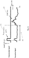
Fig. 4A ,4B , and4C illustrate concept of target echo on reception signal with time to measure target distance and first length of the target, in accordance with an exemplary embodiment of the present disclosure; -
Fig. 5 illustrates horizontal position of camera and transducer with respect to the target to measure weight of the target, in accordance with an exemplary embodiment of the present disclosure; and -
Fig. 6 illustrates a method for measuring weight of the target, in accordance with an exemplary embodiment of the present disclosure. - The detailed description of various exemplary embodiments of the disclosure is described herein with reference to the accompanying drawings. It should be noted that the embodiments are described herein in such details as to clearly communicate the disclosure. However, the amount of details provided herein is not intended to limit the anticipated variations of embodiments; on the contrary, the intention is to cover all modifications, equivalents, and alternatives falling within the spirit and scope of the present disclosure as defined by the appended claims.
- It is also to be understood that various arrangements may be devised that, although not explicitly described or shown herein, embody the principles of the present disclosure. Moreover, all statements herein reciting principles, aspects, and embodiments of the present disclosure, as well as specific examples, are intended to encompass equivalents thereof.
- The terminology used herein is for the purpose of describing particular embodiments only and is not intended to be limiting of example embodiments. As used herein, the singular forms "a", "an" and "the" are intended to include the plural forms as well, unless the context clearly indicates otherwise. It will be further understood that the terms "comprises", "comprising", "includes" and/or "including," when used herein, specify the presence of stated features, integers, steps, operations, elements and/or components, but do not preclude the presence or addition of one or more other features, integers, steps, operations, elements, components and/or groups thereof.
- It should also be noted that in some alternative implementations, the functions/acts noted may occur out of the order noted in the figures. For example, two figures shown in succession may, in fact, be executed concurrently or may sometimes be executed in the reverse order, depending upon the functionality/acts involved.
- Unless otherwise defined, all terms (including technical and scientific terms) used herein have the same meaning as commonly understood by one of ordinary skill in the art to which example embodiments belong. It will be further understood that terms, e.g., those defined in commonly used dictionaries, should be interpreted as having a meaning that is consistent with their meaning in the context of the relevant art and will not be interpreted in an idealized or overly formal sense unless expressly so defined herein.
- Various embodiments and/or implementations described herein relates to an apparatus and a method for measuring weight of a fish in an aquaculture. In an embodiment represented in
Fig. 1 , a target measuring apparatus 100 (hereinafter may be referred as apparatus 100) includes acamera 102 and atransducer 104 of a sounder. In an aspect and as show inFig. 1 , thecamera 102 and thetransducer 104 are placed next to each other. Thecamera 102 andtransducer 104 of the sounder are positioned at the same level in a vertical direction and are facing vertically downward from above thetarget 106. However, without deviating from the scope of the present disclosure, those skilled in the art can appreciate that thecamera 102 and thetransducer 104 can be placed so that both are facing vertically upward from below thetarget 106. In another aspect, thecamera 102 and thetransducer 104 may be positioned so that both are facing horizontally from the side of thetarget 106. - The
camera 102 is single camera and the sounder is a single beam echo sounder. Further, the camera may be a stereo type camera and the sounder may be dual beam sounder or multi-beam sounder. The sounder includes thetransducer 104, a transmitter, and a receiver that work as per their pre-specified profile. On activation of theapparatus 100, the transmitter of the sounder generates a transmission signal at different time interval or ping as per requirement and thetransducer 104 converts the transmission signal into a transmission wave that gets transmitted into water. The transmission wave after getting reflected from atarget 106, such as fish (hereinafter target and fish are used interchangeably) is received by thetransducer 104 to convert the reflected wave into a reception signal. Accordingly, thetransducer 104 generates the reception signal based on the reflected wave of the transmission wave on thetarget 106. Based on the received reception signal, the sounder captures echo data of thetarget 106. - Simultaneous to this capturing of the echo data by the sounder, the
camera 102 facing a first direction (x-direction) captures picture data of thetarget 106. The captured echo data and the picture data of thetarget 106 can be used to measure weight of thefish 106 in the aquaculture. The process of measurement of the weight of thefish 106 from the echo data and the picture data is described in detail with reference to the description ofFigs. 2-6 . -
Fig. 2 illustrates a block diagram of thetarget measuring apparatus 100 in accordance with an embodiment of the present disclosure. Thetarget measuring apparatus 100 includes thecamera 102, thetransducer 104 of the sounder, and atarget measuring system 200. Thetarget measuring system 200 includes a firstlength measuring module 202, a targetdistance measuring module 204, a second and thirdlength measuring module 206, and aweight measuring module 208. - The
transducer 104 transmits a transmission wave into water and generates areception signal 104a based on a reflected wave of the transmission wave on thetarget 106. Simultaneously, thecamera 102 takes apicture data 102a of thetarget 106, where thecamera 102 and thetransducer 104 are positioned facing a first direction (x-direction). - The first
length measuring module 202 receives the reception signal (which may also be referred to as echo data) from thetransducer 104 to measure a first length (height) 106a of thetarget 106. Thefirst length 106a is being measured in a direction parallel with the first direction (x-direction). - The target
distance measuring module 204 measures atarget distance 102b between thecamera 102 and thetarget 106 based on the reception signal received from thetransducer 104. As mentioned previously, thecamera 102 and thetransducer 104 of the sounder are positioned at the same level in a vertical direction and are facing vertically downward from above thetarget 106. - The second and third
length measuring module 206 measures a second length (length) 106b and a third length (width) 106c of thetarget 106 based on thepicture data 102a and thetarget distance 102b. Thesecond length 106b is being measured in a second direction (y-direction), and thethird length 106c is being measured in a third direction (z-direction) perpendicular to the second direction (y-direction), where the second and third directions form a plane perpendicular to the first direction (x-direction). - The
first length 106a of thetarget 106 generated by firstlength measuring module 202 and thesecond length 106b and thethird length 106c of thetarget 106 generated by the second and thirdlength measuring module 206 are fed to theweight measuring module 208 to measure aweight 106d of thetarget 106. - In an aspect, the
target measuring apparatus 100 may include a display device (not shown inFig. 2 ) to display results of measurement. Thecamera 102 and thetransducer 104 are connected with thetarget measuring system 200 over wire or wireless network to send the capturedpicture data 102a and thereception signal 104a, respectively. Thecamera 102 and thetransducer 104 are connected with thetarget measuring system 200 through an interface (not shown inFig. 2 ). Also, although thecamera 102 and thetransducer 104 are shown in the vicinity of thetarget measuring system 200; however, without deviating from the scope of the present disclosure, thetarget measuring system 200 may be positioned at a remote location from thecamera 102 and thetransducer 104. In another scenario, more than one pair of camera and transducer may be connected to the remotely located target measuring system so that the target measuring system can be utilized for measurement of weight of fishes present in differently located cages in which aquaculture is performed. - Various components of the
target measuring system 200 are represented inFig. 3 . In an example, thesystem 200 is in communication with thecamera 102 and/or with thetransducer 104 through a communication network. - The
system 200 includes one or more processor(s) 302. The one or more processor(s) 302 may be implemented as one or more microprocessors, microcomputers, microcontrollers, digital signal processors, central processing units, logic circuitries, and/or any devices that manipulate data based on operational instructions. Among other capabilities, the one or more processor(s) 302 are configured to fetch and execute computer-readable instructions stored in amemory 304 of thesystem 200. Thememory 304 may store one or more computer-readable instructions or routines, which may be fetched and executed to measure the weight of thetarget 106. Thememory 304 may include any non-transitory storage device including, for example, volatile memory, such as RAM, or non-volatile memory, such as EPROM, flash memory, and the like. - The
system 200 also includes an interface(s) 306. The interface(s) 306 may include a variety of interfaces, for example, interfaces for data input and output devices, referred to as I/O devices, storage devices, and the like. The interface(s) 306 facilitate communication of thesystem 200 with various devices coupled to thesystem 200. The interface(s) 306 may also provide a communication pathway for one or more components of thesystem 200. Examples of such components include, but are not limited to, module(s) 308 anddata 310. - The module(s) 308 may be implemented as a combination of hardware and programming (for example, programmable instructions) to implement one or more functionalities of the module(s) 308. In implementations described herein, such combinations of hardware and programming may be implemented in several different ways. For example, the programming for the module(s) 308 may be processor executable instructions stored on a non-transitory machine-readable storage medium and the hardware for the module(s) 308 may include a processing resource (for example, one or more processors), to execute such instructions. In the present implementations, the machine-readable storage medium may store instructions that, when executed by the processing resource, implement module(s) 308. In such examples, the
target measuring system 200 may include the machine-readable storage medium storing the instructions and the processing resource to execute the instructions, or the machine-readable storage medium may be separate but accessible to target measuringsystem 200 and the processing resource. In other examples, the module(s) 308 may be implemented by electronic circuitry. - The
data 310 includes data that is either stored or generated as a result of functionalities implemented by any of the module(s) 308. In an aspect, the module(s) 308 include the firstlength measuring module 202, the targetdistance measuring module 204, the second and thirdlength measuring module 206, theweight measuring module 208, and other module(s) 312. The other module(s) 312 may implement functionalities that supplement applications or functions performed by thetarget measuring system 200. - Further, the
data 310 may include processeddata 314 andpre-stored data 316. The processeddata 314 is generated data, for example, target distance, picture data, reception signal as an output result of functionalities implemented by one of themodules 308 and devices. On the other hand, thepre-stored data 316 includes data, such as speed of sound in the water, focal length of camera, model/fish species specific coefficient which is pre-stored in the system to be used by themodules 308 during processing. - In operation, both the
camera 102 and thetransducer 104 are synchronized with each other to acquirepicture data 102a and thereception signal 104a simultaneously. Further, as shown inFig. 1 , the coverage area of thetransducer 104 is thinner than the coverage area of thecamera 102, thereby the coverage area of thetransducer 104 is included within the coverage area of thecamera 102. Accordingly, thetransducer 104 and thecamera 102 are having an overlapping portion as shown inFig. 1 in accordance with an implementation of the present disclosure. - In a scenario in which the
camera 102 and thetransducer 104 are facing the first direction (x-direction) to acquirepicture data 102a and reflection wave that generatesreception signal 104a, thetarget measuring system 200 selects thetarget 106 which is close to the centre of thepicture 102a taken by thecamera 102. Thetarget measuring system 200 also selects thetarget 106 which has substantially a straight body on thepicture 102a, the aim being to discard thetarget 106 that is bending its body on thepicture 102a so that the second and thirdlength measuring module 206 can accurately perform measurement of thesecond length 106b andthird length 106c. Upon selection of thetarget 106, the targetdistance measuring module 204 measures target distance, i.e., Fish dist. 102b from thetransducer 104 to the selected target, i.e., fish with thereception signal 104a. The targetdistance measuring module 204 measures thetarget distance 102b in parallel to the first direction (x-direction). The targetdistance measuring module 204 measures time difference (t) 403 (as shown inFig. 4a ) between the timing at which the transmission wave ortransmission pulse 401 is transmitted from thetransducer 104 and the timing at which echo, i.e., Fish echo 405 from thetarget 106, is received by thetransducer 104 as shown inFig. 4a . The targetdistance measuring module 204 calculates the Fish dist. 102b based on equation 1:
pre-stored data 316. - As mentioned previously, the
camera 102 and thetransducer 104 are positioned at the same level in the vertical direction, thereby the targetdistance measuring module 204 sets the result obtained from equation 1 as thetarget distance 102b, namely the distance between thecamera 102 and thetarget 106. - In another embodiment, when there is position difference between the
camera 102 and thetransducer 104 in the x-direction, the position difference is required to be corrected in order to know the distance from thecamera 102 to thetarget 106. For example, if thetransducer 104 is positioned below thecamera 102, position difference between thecamera 102 and thetransducer 104 is added in the calculated Fish dist. 102b. - Referring to
Fig. 2 andFig. 4b together, the firstlength measuring module 202 measures thefirst length 106a (which may also be referred to as target/fish height 'H') by measuring duration (t echo) 404 of thefish echo 405 using equation 2:
- The measured target height 'H' 106a may be stored in the processed
data 314 for further processing. - In another embodiment, the target/
fish height H 106a can be measured using at least a part of the reception signal (δt) 406 between two positions within thefish echo 405 instead of using the whole duration of thefish echo 405. For example, referring toFig. 4c , the at least a part of the reception signal (δt) 406 between the first peak occurring in thefish echo 405 and the highest peak occurring in thefish echo 405 can be used, where the first peak indicates the position of the back of thefish 106 whereas the highest peak indicates the position of the swimbladder of thefish 106. Knowing the fish species, the at least a part of the reception signal δt can be converted into fish height (H) using the equation 3:
pre-stored data 316 for processing. - The second and third
length measuring module 206 then detects head and tail of thetarget 106 on thepicture 102a taken by thecamera 102 and measures the second length (which may also be referred to as real length 'L') 106b of thetarget 106 in the second direction (y-direction). The second length of thetarget 106 is a longitudinal size of thetarget 106. The real length of the target (fish length) 106b can be measured knowing the focal length (f) of thecamera 102 that is pre-stored in thepre-stored data 316, the distance between the head and the tail of the fish on thepicture 102a (Lpicture), and the distance between thecamera 102 and the fish (i.e., Fish dist. 102b) calculated by the targetdistance measuring module 204 and stored in theprocessing data 314. Further, the real length 'L' 106b of the target is determined by equation 4.
- The second and third
length measuring module 206 detects both sides (i.e., flanks) of thetarget 106 in the third direction (z-direction) on thepicture 102a taken by thecamera 102 and measures the third length (which may also be referred to as real width 'D') 106c of thetarget 106 in the third direction (z-direction). The third length of thetarget 106 is a lateral size of thetarget 106. The real width of thetarget 106c can be measured knowing the focal length (f) of thecamera 102 that is pre-stored in thepre-stored data 316, the distance between both sides (i.e., flanks) of the fish in the third direction (z-direction) on thepicture 102a (Dpicture), and the distance between thecamera 102 and the fish (i.e., Fish dist. 102b) calculated by the targetdistance measuring module 204 and stored in theprocessing data 314. Further, the real width 'D' 106c of the target is determined by equation 5.
- The first length of the target, i.e., height H of target is being measured in the first direction (x-direction), the second length of the target, i.e., length L of the target is being measured in the second direction (y-direction), and the third length of the target, i.e., width D of the target is being measured in the third direction (z-direction), where the third direction (z-direction) is perpendicular to the second direction (y-direction) and second and the third directions are forming a plane perpendicular to the first direction (x-direction).
- The
weight measuring module 208 is coupled with the firstlength measuring module 202 and the second and thirdlength measuring module 206 to receive thetarget length L 106b, thetarget width D 106c, and thetarget height H 106a. Theweight measuring module 208 then measures the fish weight W using equation 6:
pre-stored data 316 of the targetweight measuring system 200 with respect to each fish species. Further, thepre-stored data 316 of thesystem 200 has a plurality of models corresponding to a plurality of fish species which are pre-stored along with corresponding coefficient values. - In a case when the
camera 102 and thetransducer 104 are facing vertically down, there is the possibility that thetarget 106 is not swimming horizontally (i.e., going up or down) and therefore not swimming perpendicularly to the optical axis of thecamera 102. In this case, thetarget length L 106b appears shorter than the real length of thetarget 106. In order to reject thetarget 106 that is in this case, the target distance is measured on 2 or more pings and thetarget 106 is discarded if the distance change between 2 pings is beyond a predefined threshold. - In another embodiment as shown in
Fig. 5 , thecamera 102 and thetransducer 104 are placed so that they are facing horizontally from the side of thetarget 106. In the present case, there is the possibility that the fish is not swimming in a direction perpendicular to the optical axis of thecamera 102, as shown in theFig. 5 . In this case, the fish length measured by thecamera 102 would appear shorter. - To calculate the accurate target length, the
target 106 is detected on two or more pings by the sounder and thetarget distance 102b is measured on each ping. If the distance change between two pings is close to 0, it means that target is swimming roughly perpendicularly to the optical axis of thecamera 102 and accurate target length can be anticipated. On the other hand, if the distance change between two pings is beyond a predefined threshold, the target length cannot be measured accurately and therefore, the target is discarded. -
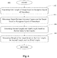
FIG. 6 illustrates amethod 600 for measuring weight of target in aquaculture environment according to an implementation of the present disclosure. The order in which themethod 600 is described is not intended to be construed as a limitation, and any number of the described method blocks can be combined in any appropriate order to carry out themethod 600 or an alternative method. Additionally, individual blocks may be deleted from themethod 600 without departing from the scope of the subject matter described herein. Thepresent method 600 illustrates particular process for weight measuring of a target, i.e., fish in the aquaculture environment. - In the present embodiment, both the
camera 102 and thetransducer 104 are facing first direction in which first length is measured. - At
block 602, themethod 600 includes measuring of first length, i.e., height 'H' 106a of the target. The firstlength measuring module 202 measures the first length of thetarget 106 based on a reception signal generated by thetransducer 104 from a reflection wave of a transmission wave on thetarget 106. The firstlength measuring module 202 uses the reception signal to measure the first length using either equation 2 or equation 3. - At
block 604, themethod 600 includes measuring oftarget distance 102b between thecamera 102 and thetarget 106. The targetdistance measuring module 204 measures the target distance between thecamera 102 and thetarget 106 based on thereception signal 104a and the equation 1. - At
block 606, themethod 600 includes measuring second and third length of the target. The second and thirdlength measuring module 206 measures second length, i.e., target length 'L' 106b in the second direction (y-direction) by detecting head and tail of thetarget 106 on thepicture 102a taken by thecamera 102. The second and thirdlength measuring module 206 measures third length, i.e., target width 'D' 106c in the third direction (z-direction) by detecting both sides of thetarget 106 on thepicture 102a taken by thecamera 102. - At
block 608, themethod 600 includes measuring weight of the target. Theweight measuring module 208 is coupled with the firstlength measuring module 202 and the second and thirdlength measuring module 206 to receive the target length L, the target width D, and the target height H. Theweight measuring module 208 measures the fish weight using equation 6. - The above description does not provide specific details of the manufacture or design of the various components. Those of skill in the art are familiar with such details, and unless departures from those techniques are set out, techniques, known, related art or later developed designs and materials should be employed. Those in the art can choose suitable manufacturing and design details.
- It should be understood, however, that all of these and similar terms are to be associated with the appropriate physical quantities and are merely convenient labels applied to these quantities. Unless specifically stated otherwise, as apparent from the discussion herein, it is appreciated that throughout the description, discussions utilizing terms, such as "measuring," or "transmitting," or the like, refer to the action and processes of an electronic control unit, or similar electronic computing device, that manipulates and transforms data represented as physical (electronic) quantities within the control unit's registers and memories into other data similarly represented as physical quantities within the control unit memories or registers or other such information storage, transmission or display devices.
- Further, the terminology used herein is for the purpose of describing particular embodiments only and is not intended to be limiting of the disclosure. It will be appreciated that several of the above-disclosed and other features and functions, or alternatives thereof, may be combined into other systems or applications. Various presently unforeseen or unanticipated alternatives, modifications, variations, or improvements therein may subsequently be made by those skilled in the art without departing from the scope of the present disclosure as encompassed by the following claims.
- The claims, as originally presented and as they may be amended, encompass variations, alternatives, modifications, improvements, equivalents, and substantial equivalents of the embodiments and teachings disclosed herein, including those that are presently unforeseen or unappreciated, and that, for example, may arise from applicants/patentees and others.
- It will be appreciated that variants of the above-disclosed and other features and functions, or alternatives thereof, may be combined into many other different systems or applications. Various presently unforeseen or unanticipated alternatives, modifications, variations, or improvements therein may be subsequently made by those skilled in the art which are also intended to be encompassed by the following claims.
Claims (11)
- A target measuring apparatus (100), comprising:a transducer (104) configured to transmit a transmission wave (401) into water and configured to generate a reception signal (104a) based on a reflection wave of the transmission wave (401) on a target (106);a camera (102) configured to take a picture (102a) of the target (106), the camera (102) and the transducer (104) facing a first direction (x-direction); anda target measuring system (200) coupled to the transducer (104) and the camera (102), wherein the target measuring system (200) comprises:a first length measuring module (202) configured to measure a first length (106a) of the target (106) based on the reception signal (104a), the first length (106a) being measured in a direction parallel with the first direction (x-direction);a target distance measuring module (204) configured to measure a target distance (102b) between the camera (102) and the target (106) based on the reception signal (104a);a second and third length measuring module (206) configured to measure a second length (106b) and a third length (106c) of the target (106) based on the picture (102a) and the target distance (102b), the second length (106b) being measured in a second direction (y-direction), the third length (106c) being measured in a third direction (z-direction) perpendicular to the second direction (y-direction), the second and third directions forming a plane perpendicular to the first direction (x-direction); anda weight measuring module (208) configured to measure a weight of the target (106) based on the first length (106a), the second length (106b), and the third length (106c) of the target (106).
- The target measuring apparatus (100) of claim 1, wherein the first length measuring module (202) measures the first length (106a) based on a measure of a duration of at least a part of the reception signal (104a) that corresponds to the target (106).
- The target measuring apparatus (100) of claim 1 or claim 2, wherein the second and third length measuring module (206) measures: the second length (106b) based on a measure of a longitudinal size of the target (106) on the picture (102a), and the third length (106c) based on a measure of a lateral size of the target (106) on the picture (102a).
- The target measuring apparatus (100) of claim 3, wherein the second and third length measuring module (206) measures the second length (106b) and the third length (106c) based on a focal length (f) of the camera (102).
- The target measuring apparatus (100) of any of the preceding claims, wherein the weight measuring module (208) measures the weight of the target (106) based on a model of the target (106), the model linking the first length (106a), the second length (106b), and the third length (106c) of the target (106) with the weight of the target.
- The target measuring apparatus (100) of any of the preceding claims, wherein
the first direction (x-direction) is vertical;
the first length (106a) corresponds to a target height;
the second length (106b) corresponds to a target length; and
the third length (106c) corresponds to a target width. - The target measuring apparatus (100) of any of the preceding claims, wherein the target measuring system (200) is further configured to select the target (106) that is close to centre of the picture (102a).
- The target measuring apparatus (100) of any of the preceding claims, wherein the target measuring system (200) is further configured to select the target (106) having a straight body on the picture (102a).
- The target measuring apparatus (100) of any of the preceding claims, wherein the target measuring system (200) is further configured to select the target (106) that is swimming substantially perpendicular to an optical axis of the camera (102).
- The target measuring apparatus (100) of any of the preceding claims, wherein the target (106) is a fish to be raised in an aquaculture environment.
- A method (600) for measuring a weight of a target (106), comprising
measuring (602) a first length (106a) of the target (106) based on a reception signal (104a) generated by a transducer (104) based on a reflection wave of a transmission wave transmitted on the target (106);
measuring (604) a target distance (102b) between a camera (102) and the target (106) based on the reception signal (104a), the camera (102) being configured to take a picture (102a) of the target (106), the camera (102) and the transducer (104) facing a first direction (x-direction) parallel to a direction in which the first length (106a) is measured;
measuring (606) a second length (106b) and a third length (106c) of the target (106) based on the picture (102a) and the target distance (102b), the second length (106b) being measured in a second direction (y-direction), the third length (106c) being measured in a third direction (z-direction) perpendicular to the second direction (y-direction), the second and third directions forming a plane perpendicular to the first direction (x-direction); and
measuring (608) a weight of the target (106) based on the first length (106a), the second length (106b), and the third length (106c) of the target (106).
Priority Applications (3)
| Application Number | Priority Date | Filing Date | Title |
|---|---|---|---|
| EP19180594.4A EP3754374B1 (en) | 2019-06-17 | 2019-06-17 | Fish weight measuring apparatus |
| ES19180594T ES3008953T3 (en) | 2019-06-17 | 2019-06-17 | Fish weight measuring apparatus |
| DK19180594.4T DK3754374T3 (en) | 2019-06-17 | 2019-06-17 | Fish weighing device |
Applications Claiming Priority (1)
| Application Number | Priority Date | Filing Date | Title |
|---|---|---|---|
| EP19180594.4A EP3754374B1 (en) | 2019-06-17 | 2019-06-17 | Fish weight measuring apparatus |
Publications (2)
| Publication Number | Publication Date |
|---|---|
| EP3754374A1 true EP3754374A1 (en) | 2020-12-23 |
| EP3754374B1 EP3754374B1 (en) | 2024-11-13 |
Family
ID=66951796
Family Applications (1)
| Application Number | Title | Priority Date | Filing Date |
|---|---|---|---|
| EP19180594.4A Active EP3754374B1 (en) | 2019-06-17 | 2019-06-17 | Fish weight measuring apparatus |
Country Status (3)
| Country | Link |
|---|---|
| EP (1) | EP3754374B1 (en) |
| DK (1) | DK3754374T3 (en) |
| ES (1) | ES3008953T3 (en) |
Cited By (6)
| Publication number | Priority date | Publication date | Assignee | Title |
|---|---|---|---|---|
| CN115137395A (en) * | 2021-03-31 | 2022-10-04 | 古野电气株式会社 | Fish size calculation apparatus and method, and non-volatile computer-readable medium |
| CN115137396A (en) * | 2021-03-31 | 2022-10-04 | 古野电气株式会社 | Aquatic animal shape calculation apparatus and method, and computer readable medium |
| JP2022158949A (en) * | 2021-03-31 | 2022-10-17 | 古野電気株式会社 | Aquatic animal shape calculation device and method |
| EP4141486A1 (en) * | 2021-08-31 | 2023-03-01 | Furuno Electric Co., Ltd. | Device and method for fish detection |
| NO20220175A1 (en) * | 2022-02-08 | 2023-08-09 | Scantrol Deep Vision As | Underwater sensor for use in a trawl |
| JP7672186B1 (en) * | 2025-03-04 | 2025-05-07 | 株式会社AquaFusion | Seaweed bed evaluation system and seaweed bed evaluation method |
Citations (4)
| Publication number | Priority date | Publication date | Assignee | Title |
|---|---|---|---|---|
| US20060018197A1 (en) * | 2004-07-20 | 2006-01-26 | Biosonics, Inc. | Acoustic biomass monitor |
| US9541645B2 (en) * | 2014-02-20 | 2017-01-10 | Furuno Electric Co., Ltd. | Detecting device, fish finder and detecting method |
| EP3316220A1 (en) * | 2016-10-26 | 2018-05-02 | Balfegó & Balfegó S.L. | Method for determining tuna biomass in a water zone and corresponding system |
| WO2019017132A1 (en) * | 2017-07-19 | 2019-01-24 | 古野電気株式会社 | Growth state measurement apparatus and growth state measurement method |
-
2019
- 2019-06-17 DK DK19180594.4T patent/DK3754374T3/en active
- 2019-06-17 ES ES19180594T patent/ES3008953T3/en active Active
- 2019-06-17 EP EP19180594.4A patent/EP3754374B1/en active Active
Patent Citations (4)
| Publication number | Priority date | Publication date | Assignee | Title |
|---|---|---|---|---|
| US20060018197A1 (en) * | 2004-07-20 | 2006-01-26 | Biosonics, Inc. | Acoustic biomass monitor |
| US9541645B2 (en) * | 2014-02-20 | 2017-01-10 | Furuno Electric Co., Ltd. | Detecting device, fish finder and detecting method |
| EP3316220A1 (en) * | 2016-10-26 | 2018-05-02 | Balfegó & Balfegó S.L. | Method for determining tuna biomass in a water zone and corresponding system |
| WO2019017132A1 (en) * | 2017-07-19 | 2019-01-24 | 古野電気株式会社 | Growth state measurement apparatus and growth state measurement method |
Non-Patent Citations (3)
| Title |
|---|
| GODLEWSKA M.: "Target strength of freshwater fishes at 420 kHz measured in cages", HYDROACOUSTICS, vol. 7, 2004, pages 55 - 62 |
| HARVEY ET AL.: "The accuracy and precision of underwater measurements of length and maximum body depth of southern bluefin tuna (Thunnus maccoyii) with a stereo-video camera system", FISHERIES RESEARCH, vol. 63, no. 3, 2003, pages 315 - 326 |
| V PUIG ET AL: "Biomass estimation of bluefin tuna in sea cages by the combined use of acoustic and optical techniques", VOL. SCI. PAP. ICCAT, 1 January 2012 (2012-01-01), pages 284 - 290, XP055438276, Retrieved from the Internet <URL:http://www.iccat.int/Documents/CVSP/CV068_2012/no_1/CV068010284.pdf> * |
Cited By (10)
| Publication number | Priority date | Publication date | Assignee | Title |
|---|---|---|---|---|
| CN115137395A (en) * | 2021-03-31 | 2022-10-04 | 古野电气株式会社 | Fish size calculation apparatus and method, and non-volatile computer-readable medium |
| CN115137396A (en) * | 2021-03-31 | 2022-10-04 | 古野电气株式会社 | Aquatic animal shape calculation apparatus and method, and computer readable medium |
| EP4067934A1 (en) * | 2021-03-31 | 2022-10-05 | Furuno Electric Co., Ltd. | Aquatic animal shape calculation device and method |
| JP2022158949A (en) * | 2021-03-31 | 2022-10-17 | 古野電気株式会社 | Aquatic animal shape calculation device and method |
| JP2022158950A (en) * | 2021-03-31 | 2022-10-17 | 古野電気株式会社 | Fish size calculation device and fish size calculation method |
| EP4141486A1 (en) * | 2021-08-31 | 2023-03-01 | Furuno Electric Co., Ltd. | Device and method for fish detection |
| NO20220175A1 (en) * | 2022-02-08 | 2023-08-09 | Scantrol Deep Vision As | Underwater sensor for use in a trawl |
| WO2023153934A1 (en) * | 2022-02-08 | 2023-08-17 | Scantrol Deep Vision As | An underwater sensor, and a method for adjusting towing power of a vessel |
| NO347510B1 (en) * | 2022-02-08 | 2023-12-04 | Scantrol Deep Vision As | Underwater sensor for use in a trawl |
| JP7672186B1 (en) * | 2025-03-04 | 2025-05-07 | 株式会社AquaFusion | Seaweed bed evaluation system and seaweed bed evaluation method |
Also Published As
| Publication number | Publication date |
|---|---|
| ES3008953T3 (en) | 2025-03-25 |
| DK3754374T3 (en) | 2025-01-02 |
| EP3754374B1 (en) | 2024-11-13 |
Similar Documents
| Publication | Publication Date | Title |
|---|---|---|
| EP3754374A1 (en) | Fish weight measuring apparatus | |
| Zimmer et al. | Off-axis effects on the multipulse structure of sperm whale usual clicks with implications for sound production | |
| US8625391B2 (en) | Networked sonar observation of selected seabed environments | |
| EP3090498B1 (en) | Method and apparatus for synchronizing clocks underwater using light and sound | |
| EP3153884B1 (en) | Detection apparatus, fish finder, and radar | |
| GB2503351A (en) | Underwater detection device | |
| EP1462819A3 (en) | Ultrasonic imaging apparatus with multiple transmit beams and reduced sidelobes | |
| JP6714261B2 (en) | Underwater detection device, underwater detection method, and underwater detection program | |
| CN101900808B (en) | Delay parameter computation method for multi-channel scanning and device thereof | |
| CN105827937A (en) | Imaging device and imaging method | |
| US9310483B2 (en) | Device and method for transceiving ultrasonic wave | |
| JP6922958B2 (en) | Number counting device and number counting method | |
| CN105759280A (en) | Laser triangulation system safe for human eyes | |
| EP2849560B1 (en) | Trawl height indicator | |
| CN115328131A (en) | Obstacle avoidance method and device for unmanned ship, unmanned ship and storage medium | |
| US20120265073A1 (en) | Ultrasound system and method for forming bc-mode image | |
| JP4354736B2 (en) | Ultrasonic transceiver | |
| US20150138921A1 (en) | Acoustic distance measuring for a trawl | |
| RU2697430C1 (en) | Hydroacoustic system for fish monitoring in cages of industrial aquaculture enterprises | |
| Hamano et al. | Development of a new monitoring methodology for counting bluefin tuna in net pens | |
| CN110187324A (en) | Method and apparatus for optical distance measurement | |
| EP4067934A1 (en) | Aquatic animal shape calculation device and method | |
| KR20170055330A (en) | Apparatus and method for processing data of side scan sonar | |
| JP2025039065A (en) | Fish weight measuring method and fish weight measuring device | |
| RU98087U1 (en) | FISH SEARCH DEVICE |
Legal Events
| Date | Code | Title | Description |
|---|---|---|---|
| PUAI | Public reference made under article 153(3) epc to a published international application that has entered the european phase |
Free format text: ORIGINAL CODE: 0009012 |
|
| STAA | Information on the status of an ep patent application or granted ep patent |
Free format text: STATUS: THE APPLICATION HAS BEEN PUBLISHED |
|
| AK | Designated contracting states |
Kind code of ref document: A1 Designated state(s): AL AT BE BG CH CY CZ DE DK EE ES FI FR GB GR HR HU IE IS IT LI LT LU LV MC MK MT NL NO PL PT RO RS SE SI SK SM TR |
|
| AX | Request for extension of the european patent |
Extension state: BA ME |
|
| STAA | Information on the status of an ep patent application or granted ep patent |
Free format text: STATUS: REQUEST FOR EXAMINATION WAS MADE |
|
| 17P | Request for examination filed |
Effective date: 20210120 |
|
| RBV | Designated contracting states (corrected) |
Designated state(s): AL AT BE BG CH CY CZ DE DK EE ES FI FR GB GR HR HU IE IS IT LI LT LU LV MC MK MT NL NO PL PT RO RS SE SI SK SM TR |
|
| STAA | Information on the status of an ep patent application or granted ep patent |
Free format text: STATUS: EXAMINATION IS IN PROGRESS |
|
| 17Q | First examination report despatched |
Effective date: 20220517 |
|
| REG | Reference to a national code |
Ref country code: DE Ref legal event code: R079 Free format text: PREVIOUS MAIN CLASS: G01S0015020000 Ipc: G01S0015960000 Ref country code: DE Ref legal event code: R079 Ref document number: 602019061823 Country of ref document: DE Free format text: PREVIOUS MAIN CLASS: G01S0015020000 Ipc: G01S0015960000 |
|
| GRAP | Despatch of communication of intention to grant a patent |
Free format text: ORIGINAL CODE: EPIDOSNIGR1 |
|
| STAA | Information on the status of an ep patent application or granted ep patent |
Free format text: STATUS: GRANT OF PATENT IS INTENDED |
|
| RAP3 | Party data changed (applicant data changed or rights of an application transferred) |
Owner name: FURUNO ELECTRIC COMPANY LIMITED |
|
| RIC1 | Information provided on ipc code assigned before grant |
Ipc: G01S 7/539 20060101ALI20240223BHEP Ipc: G01S 15/86 20200101ALI20240223BHEP Ipc: G01S 15/96 20060101AFI20240223BHEP |
|
| RIN1 | Information on inventor provided before grant (corrected) |
Inventor name: YAMAGUCHI, TAKEHARU Inventor name: KAWAI, MASATO Inventor name: ITO, MASANORI |
|
| INTG | Intention to grant announced |
Effective date: 20240312 |
|
| GRAJ | Information related to disapproval of communication of intention to grant by the applicant or resumption of examination proceedings by the epo deleted |
Free format text: ORIGINAL CODE: EPIDOSDIGR1 |
|
| STAA | Information on the status of an ep patent application or granted ep patent |
Free format text: STATUS: EXAMINATION IS IN PROGRESS |
|
| GRAP | Despatch of communication of intention to grant a patent |
Free format text: ORIGINAL CODE: EPIDOSNIGR1 |
|
| STAA | Information on the status of an ep patent application or granted ep patent |
Free format text: STATUS: GRANT OF PATENT IS INTENDED |
|
| INTC | Intention to grant announced (deleted) | ||
| INTG | Intention to grant announced |
Effective date: 20240705 |
|
| GRAS | Grant fee paid |
Free format text: ORIGINAL CODE: EPIDOSNIGR3 |
|
| GRAA | (expected) grant |
Free format text: ORIGINAL CODE: 0009210 |
|
| STAA | Information on the status of an ep patent application or granted ep patent |
Free format text: STATUS: THE PATENT HAS BEEN GRANTED |
|
| AK | Designated contracting states |
Kind code of ref document: B1 Designated state(s): AL AT BE BG CH CY CZ DE DK EE ES FI FR GB GR HR HU IE IS IT LI LT LU LV MC MK MT NL NO PL PT RO RS SE SI SK SM TR |
|
| REG | Reference to a national code |
Ref country code: GB Ref legal event code: FG4D |
|
| REG | Reference to a national code |
Ref country code: CH Ref legal event code: EP |
|
| REG | Reference to a national code |
Ref country code: DE Ref legal event code: R096 Ref document number: 602019061823 Country of ref document: DE |
|
| REG | Reference to a national code |
Ref country code: IE Ref legal event code: FG4D |
|
| REG | Reference to a national code |
Ref country code: DK Ref legal event code: T3 Effective date: 20241219 |
|
| REG | Reference to a national code |
Ref country code: LT Ref legal event code: MG9D |
|
| REG | Reference to a national code |
Ref country code: NL Ref legal event code: MP Effective date: 20241113 |
|
| REG | Reference to a national code |
Ref country code: ES Ref legal event code: FG2A Ref document number: 3008953 Country of ref document: ES Kind code of ref document: T3 Effective date: 20250325 |
|
| PG25 | Lapsed in a contracting state [announced via postgrant information from national office to epo] |
Ref country code: PT Free format text: LAPSE BECAUSE OF FAILURE TO SUBMIT A TRANSLATION OF THE DESCRIPTION OR TO PAY THE FEE WITHIN THE PRESCRIBED TIME-LIMIT Effective date: 20250313 Ref country code: HR Free format text: LAPSE BECAUSE OF FAILURE TO SUBMIT A TRANSLATION OF THE DESCRIPTION OR TO PAY THE FEE WITHIN THE PRESCRIBED TIME-LIMIT Effective date: 20241113 Ref country code: IS Free format text: LAPSE BECAUSE OF FAILURE TO SUBMIT A TRANSLATION OF THE DESCRIPTION OR TO PAY THE FEE WITHIN THE PRESCRIBED TIME-LIMIT Effective date: 20250313 |
|
| PG25 | Lapsed in a contracting state [announced via postgrant information from national office to epo] |
Ref country code: NL Free format text: LAPSE BECAUSE OF FAILURE TO SUBMIT A TRANSLATION OF THE DESCRIPTION OR TO PAY THE FEE WITHIN THE PRESCRIBED TIME-LIMIT Effective date: 20241113 Ref country code: FI Free format text: LAPSE BECAUSE OF FAILURE TO SUBMIT A TRANSLATION OF THE DESCRIPTION OR TO PAY THE FEE WITHIN THE PRESCRIBED TIME-LIMIT Effective date: 20241113 |
|
| REG | Reference to a national code |
Ref country code: AT Ref legal event code: MK05 Ref document number: 1742089 Country of ref document: AT Kind code of ref document: T Effective date: 20241113 |
|
| PG25 | Lapsed in a contracting state [announced via postgrant information from national office to epo] |
Ref country code: BG Free format text: LAPSE BECAUSE OF FAILURE TO SUBMIT A TRANSLATION OF THE DESCRIPTION OR TO PAY THE FEE WITHIN THE PRESCRIBED TIME-LIMIT Effective date: 20241113 |
|
| PG25 | Lapsed in a contracting state [announced via postgrant information from national office to epo] |
Ref country code: LV Free format text: LAPSE BECAUSE OF FAILURE TO SUBMIT A TRANSLATION OF THE DESCRIPTION OR TO PAY THE FEE WITHIN THE PRESCRIBED TIME-LIMIT Effective date: 20241113 Ref country code: AT Free format text: LAPSE BECAUSE OF FAILURE TO SUBMIT A TRANSLATION OF THE DESCRIPTION OR TO PAY THE FEE WITHIN THE PRESCRIBED TIME-LIMIT Effective date: 20241113 Ref country code: GR Free format text: LAPSE BECAUSE OF FAILURE TO SUBMIT A TRANSLATION OF THE DESCRIPTION OR TO PAY THE FEE WITHIN THE PRESCRIBED TIME-LIMIT Effective date: 20250214 |
|
| PG25 | Lapsed in a contracting state [announced via postgrant information from national office to epo] |
Ref country code: PL Free format text: LAPSE BECAUSE OF FAILURE TO SUBMIT A TRANSLATION OF THE DESCRIPTION OR TO PAY THE FEE WITHIN THE PRESCRIBED TIME-LIMIT Effective date: 20241113 |
|
| PG25 | Lapsed in a contracting state [announced via postgrant information from national office to epo] |
Ref country code: RS Free format text: LAPSE BECAUSE OF FAILURE TO SUBMIT A TRANSLATION OF THE DESCRIPTION OR TO PAY THE FEE WITHIN THE PRESCRIBED TIME-LIMIT Effective date: 20250213 |
|
| PG25 | Lapsed in a contracting state [announced via postgrant information from national office to epo] |
Ref country code: SM Free format text: LAPSE BECAUSE OF FAILURE TO SUBMIT A TRANSLATION OF THE DESCRIPTION OR TO PAY THE FEE WITHIN THE PRESCRIBED TIME-LIMIT Effective date: 20241113 |
|
| PGFP | Annual fee paid to national office [announced via postgrant information from national office to epo] |
Ref country code: GB Payment date: 20250501 Year of fee payment: 7 Ref country code: DK Payment date: 20250618 Year of fee payment: 7 |
|
| PGFP | Annual fee paid to national office [announced via postgrant information from national office to epo] |
Ref country code: NO Payment date: 20250610 Year of fee payment: 7 |
|
| PG25 | Lapsed in a contracting state [announced via postgrant information from national office to epo] |
Ref country code: EE Free format text: LAPSE BECAUSE OF FAILURE TO SUBMIT A TRANSLATION OF THE DESCRIPTION OR TO PAY THE FEE WITHIN THE PRESCRIBED TIME-LIMIT Effective date: 20241113 |
|
| PGFP | Annual fee paid to national office [announced via postgrant information from national office to epo] |
Ref country code: FR Payment date: 20250508 Year of fee payment: 7 |
|
| PG25 | Lapsed in a contracting state [announced via postgrant information from national office to epo] |
Ref country code: RO Free format text: LAPSE BECAUSE OF FAILURE TO SUBMIT A TRANSLATION OF THE DESCRIPTION OR TO PAY THE FEE WITHIN THE PRESCRIBED TIME-LIMIT Effective date: 20241113 |
|
| PG25 | Lapsed in a contracting state [announced via postgrant information from national office to epo] |
Ref country code: SK Free format text: LAPSE BECAUSE OF FAILURE TO SUBMIT A TRANSLATION OF THE DESCRIPTION OR TO PAY THE FEE WITHIN THE PRESCRIBED TIME-LIMIT Effective date: 20241113 |
|
| PG25 | Lapsed in a contracting state [announced via postgrant information from national office to epo] |
Ref country code: CZ Free format text: LAPSE BECAUSE OF FAILURE TO SUBMIT A TRANSLATION OF THE DESCRIPTION OR TO PAY THE FEE WITHIN THE PRESCRIBED TIME-LIMIT Effective date: 20241113 |
|
| PG25 | Lapsed in a contracting state [announced via postgrant information from national office to epo] |
Ref country code: IT Free format text: LAPSE BECAUSE OF FAILURE TO SUBMIT A TRANSLATION OF THE DESCRIPTION OR TO PAY THE FEE WITHIN THE PRESCRIBED TIME-LIMIT Effective date: 20241113 |
|
| REG | Reference to a national code |
Ref country code: DE Ref legal event code: R097 Ref document number: 602019061823 Country of ref document: DE |
|
| PG25 | Lapsed in a contracting state [announced via postgrant information from national office to epo] |
Ref country code: SE Free format text: LAPSE BECAUSE OF FAILURE TO SUBMIT A TRANSLATION OF THE DESCRIPTION OR TO PAY THE FEE WITHIN THE PRESCRIBED TIME-LIMIT Effective date: 20241113 |
|
| PLBE | No opposition filed within time limit |
Free format text: ORIGINAL CODE: 0009261 |
|
| STAA | Information on the status of an ep patent application or granted ep patent |
Free format text: STATUS: NO OPPOSITION FILED WITHIN TIME LIMIT |
|
| PGFP | Annual fee paid to national office [announced via postgrant information from national office to epo] |
Ref country code: ES Payment date: 20250701 Year of fee payment: 7 |
|
| 26N | No opposition filed |
Effective date: 20250814 |
|
| REG | Reference to a national code |
Ref country code: DE Ref legal event code: R119 Ref document number: 602019061823 Country of ref document: DE |
|
| REG | Reference to a national code |
Ref country code: CH Ref legal event code: H13 Free format text: ST27 STATUS EVENT CODE: U-0-0-H10-H13 (AS PROVIDED BY THE NATIONAL OFFICE) Effective date: 20260127 |
|
| PG25 | Lapsed in a contracting state [announced via postgrant information from national office to epo] |
Ref country code: MC Free format text: LAPSE BECAUSE OF FAILURE TO SUBMIT A TRANSLATION OF THE DESCRIPTION OR TO PAY THE FEE WITHIN THE PRESCRIBED TIME-LIMIT Effective date: 20241113 |
|
| PG25 | Lapsed in a contracting state [announced via postgrant information from national office to epo] |
Ref country code: LU Free format text: LAPSE BECAUSE OF NON-PAYMENT OF DUE FEES Effective date: 20250617 |
|
| REG | Reference to a national code |
Ref country code: BE Ref legal event code: MM Effective date: 20250630 |
|
| PG25 | Lapsed in a contracting state [announced via postgrant information from national office to epo] |
Ref country code: DE Free format text: LAPSE BECAUSE OF NON-PAYMENT OF DUE FEES Effective date: 20260101 Ref country code: IE Free format text: LAPSE BECAUSE OF NON-PAYMENT OF DUE FEES Effective date: 20250617 |
|
| PG25 | Lapsed in a contracting state [announced via postgrant information from national office to epo] |
Ref country code: BE Free format text: LAPSE BECAUSE OF NON-PAYMENT OF DUE FEES Effective date: 20250630 |
|
| PG25 | Lapsed in a contracting state [announced via postgrant information from national office to epo] |
Ref country code: CH Free format text: LAPSE BECAUSE OF NON-PAYMENT OF DUE FEES Effective date: 20250630 |