EP3754270A1 - Accumulator, and compressor for air conditioning - Google Patents
Accumulator, and compressor for air conditioning Download PDFInfo
- Publication number
- EP3754270A1 EP3754270A1 EP18906496.7A EP18906496A EP3754270A1 EP 3754270 A1 EP3754270 A1 EP 3754270A1 EP 18906496 A EP18906496 A EP 18906496A EP 3754270 A1 EP3754270 A1 EP 3754270A1
- Authority
- EP
- European Patent Office
- Prior art keywords
- pipe
- compressor
- accumulator
- support member
- center
- Prior art date
- Legal status (The legal status is an assumption and is not a legal conclusion. Google has not performed a legal analysis and makes no representation as to the accuracy of the status listed.)
- Granted
Links
Images

Classifications
-
- F—MECHANICAL ENGINEERING; LIGHTING; HEATING; WEAPONS; BLASTING
- F25—REFRIGERATION OR COOLING; COMBINED HEATING AND REFRIGERATION SYSTEMS; HEAT PUMP SYSTEMS; MANUFACTURE OR STORAGE OF ICE; LIQUEFACTION SOLIDIFICATION OF GASES
- F25B—REFRIGERATION MACHINES, PLANTS OR SYSTEMS; COMBINED HEATING AND REFRIGERATION SYSTEMS; HEAT PUMP SYSTEMS
- F25B43/00—Arrangements for separating or purifying gases or liquids; Arrangements for vaporising the residuum of liquid refrigerant, e.g. by heat
- F25B43/006—Accumulators
-
- F—MECHANICAL ENGINEERING; LIGHTING; HEATING; WEAPONS; BLASTING
- F04—POSITIVE - DISPLACEMENT MACHINES FOR LIQUIDS; PUMPS FOR LIQUIDS OR ELASTIC FLUIDS
- F04B—POSITIVE-DISPLACEMENT MACHINES FOR LIQUIDS; PUMPS
- F04B39/00—Component parts, details, or accessories, of pumps or pumping systems specially adapted for elastic fluids, not otherwise provided for in, or of interest apart from, groups F04B25/00 - F04B37/00
- F04B39/12—Casings; Cylinders; Cylinder heads; Fluid connections
-
- F—MECHANICAL ENGINEERING; LIGHTING; HEATING; WEAPONS; BLASTING
- F04—POSITIVE - DISPLACEMENT MACHINES FOR LIQUIDS; PUMPS FOR LIQUIDS OR ELASTIC FLUIDS
- F04B—POSITIVE-DISPLACEMENT MACHINES FOR LIQUIDS; PUMPS
- F04B39/00—Component parts, details, or accessories, of pumps or pumping systems specially adapted for elastic fluids, not otherwise provided for in, or of interest apart from, groups F04B25/00 - F04B37/00
- F04B39/16—Filtration; Moisture separation
-
- F—MECHANICAL ENGINEERING; LIGHTING; HEATING; WEAPONS; BLASTING
- F04—POSITIVE - DISPLACEMENT MACHINES FOR LIQUIDS; PUMPS FOR LIQUIDS OR ELASTIC FLUIDS
- F04C—ROTARY-PISTON, OR OSCILLATING-PISTON, POSITIVE-DISPLACEMENT MACHINES FOR LIQUIDS; ROTARY-PISTON, OR OSCILLATING-PISTON, POSITIVE-DISPLACEMENT PUMPS
- F04C23/00—Combinations of two or more pumps, each being of rotary-piston or oscillating-piston type, specially adapted for elastic fluids; Pumping installations specially adapted for elastic fluids; Multi-stage pumps specially adapted for elastic fluids
- F04C23/008—Hermetic pumps
-
- F—MECHANICAL ENGINEERING; LIGHTING; HEATING; WEAPONS; BLASTING
- F04—POSITIVE - DISPLACEMENT MACHINES FOR LIQUIDS; PUMPS FOR LIQUIDS OR ELASTIC FLUIDS
- F04C—ROTARY-PISTON, OR OSCILLATING-PISTON, POSITIVE-DISPLACEMENT MACHINES FOR LIQUIDS; ROTARY-PISTON, OR OSCILLATING-PISTON, POSITIVE-DISPLACEMENT PUMPS
- F04C29/00—Component parts, details or accessories of pumps or pumping installations, not provided for in groups F04C18/00 - F04C28/00
- F04C29/06—Silencing
-
- F—MECHANICAL ENGINEERING; LIGHTING; HEATING; WEAPONS; BLASTING
- F04—POSITIVE - DISPLACEMENT MACHINES FOR LIQUIDS; PUMPS FOR LIQUIDS OR ELASTIC FLUIDS
- F04C—ROTARY-PISTON, OR OSCILLATING-PISTON, POSITIVE-DISPLACEMENT MACHINES FOR LIQUIDS; ROTARY-PISTON, OR OSCILLATING-PISTON, POSITIVE-DISPLACEMENT PUMPS
- F04C18/00—Rotary-piston pumps specially adapted for elastic fluids
- F04C18/30—Rotary-piston pumps specially adapted for elastic fluids having the characteristics covered by two or more of groups F04C18/02, F04C18/08, F04C18/22, F04C18/24, F04C18/48, or having the characteristics covered by one of these groups together with some other type of movement between co-operating members
- F04C18/34—Rotary-piston pumps specially adapted for elastic fluids having the characteristics covered by two or more of groups F04C18/02, F04C18/08, F04C18/22, F04C18/24, F04C18/48, or having the characteristics covered by one of these groups together with some other type of movement between co-operating members having the movement defined in group F04C18/08 or F04C18/22 and relative reciprocation between the co-operating members
- F04C18/356—Rotary-piston pumps specially adapted for elastic fluids having the characteristics covered by two or more of groups F04C18/02, F04C18/08, F04C18/22, F04C18/24, F04C18/48, or having the characteristics covered by one of these groups together with some other type of movement between co-operating members having the movement defined in group F04C18/08 or F04C18/22 and relative reciprocation between the co-operating members with vanes reciprocating with respect to the outer member
-
- F—MECHANICAL ENGINEERING; LIGHTING; HEATING; WEAPONS; BLASTING
- F04—POSITIVE - DISPLACEMENT MACHINES FOR LIQUIDS; PUMPS FOR LIQUIDS OR ELASTIC FLUIDS
- F04C—ROTARY-PISTON, OR OSCILLATING-PISTON, POSITIVE-DISPLACEMENT MACHINES FOR LIQUIDS; ROTARY-PISTON, OR OSCILLATING-PISTON, POSITIVE-DISPLACEMENT PUMPS
- F04C2240/00—Components
- F04C2240/80—Other components
- F04C2240/804—Accumulators for refrigerant circuits
-
- F—MECHANICAL ENGINEERING; LIGHTING; HEATING; WEAPONS; BLASTING
- F04—POSITIVE - DISPLACEMENT MACHINES FOR LIQUIDS; PUMPS FOR LIQUIDS OR ELASTIC FLUIDS
- F04C—ROTARY-PISTON, OR OSCILLATING-PISTON, POSITIVE-DISPLACEMENT MACHINES FOR LIQUIDS; ROTARY-PISTON, OR OSCILLATING-PISTON, POSITIVE-DISPLACEMENT PUMPS
- F04C2240/00—Components
- F04C2240/80—Other components
- F04C2240/805—Fastening means, e.g. bolts
-
- F—MECHANICAL ENGINEERING; LIGHTING; HEATING; WEAPONS; BLASTING
- F04—POSITIVE - DISPLACEMENT MACHINES FOR LIQUIDS; PUMPS FOR LIQUIDS OR ELASTIC FLUIDS
- F04C—ROTARY-PISTON, OR OSCILLATING-PISTON, POSITIVE-DISPLACEMENT MACHINES FOR LIQUIDS; ROTARY-PISTON, OR OSCILLATING-PISTON, POSITIVE-DISPLACEMENT PUMPS
- F04C2240/00—Components
- F04C2240/80—Other components
- F04C2240/806—Pipes for fluids; Fittings therefor
-
- F—MECHANICAL ENGINEERING; LIGHTING; HEATING; WEAPONS; BLASTING
- F04—POSITIVE - DISPLACEMENT MACHINES FOR LIQUIDS; PUMPS FOR LIQUIDS OR ELASTIC FLUIDS
- F04C—ROTARY-PISTON, OR OSCILLATING-PISTON, POSITIVE-DISPLACEMENT MACHINES FOR LIQUIDS; ROTARY-PISTON, OR OSCILLATING-PISTON, POSITIVE-DISPLACEMENT PUMPS
- F04C2270/00—Control; Monitoring or safety arrangements
- F04C2270/12—Vibration
-
- F—MECHANICAL ENGINEERING; LIGHTING; HEATING; WEAPONS; BLASTING
- F25—REFRIGERATION OR COOLING; COMBINED HEATING AND REFRIGERATION SYSTEMS; HEAT PUMP SYSTEMS; MANUFACTURE OR STORAGE OF ICE; LIQUEFACTION SOLIDIFICATION OF GASES
- F25B—REFRIGERATION MACHINES, PLANTS OR SYSTEMS; COMBINED HEATING AND REFRIGERATION SYSTEMS; HEAT PUMP SYSTEMS
- F25B31/00—Compressor arrangements
- F25B31/02—Compressor arrangements of motor-compressor units
- F25B31/026—Compressor arrangements of motor-compressor units with compressor of rotary type
Definitions
- the present invention relates to an accumulator and a compressor for air conditioning.
- PTL 1 discloses a structure in which a pipe for supplying a refrigerant gas from an accumulator to a compressor body is supported by a support member (connecting member) provided in the accumulator.
- an exciting force caused by magnetism of a motor driving the compressor body or an exciting force caused by pulsation of the compressor body acts thereon.
- the exciting force caused by pulsation of the compressor body may cause vibration of a pipe in the accumulator and the vibration may be transmitted to the accumulator via the support member, which may cause noise.
- the present invention has been made in view of such circumstances and an object thereof is to suppress vibration generated in an accumulator provided adjacent to a compressor body of a compressor for air conditioning and to reduce noise generated in the compressor for air conditioning.
- an accumulator which is provided adjacent to a compressor body of a compressor for air conditioning and which supplies a refrigerant gas subjected to gas-liquid separation from a container body to the compressor body via a pipe.
- the accumulator includes a support member of which an outer edge is attached to an inner wall of the container body, the support member including a support hole that supports the pipe inside the container body and a center of the support hole is positioned away from a center line that passes through a center of the support member along a direction of a most dominant exciting force transmitted from the compressor body.
- a portion of the most dominant exciting force transmitted from the pipe to the support member is dispersed in a direction in which the support member is twisted.
- an exciting force that is transmitted to the container body of the accumulator from the pipe via the support member can be reduced. Therefore, according to the accumulator in the present invention, vibration generated at the accumulator provided adjacent to the compressor body of the compressor for air conditioning can be suppressed and noise generated at the compressor for air conditioning can be reduced.
- the support member includes a plurality of through-holes provided at positions different from the support hole, a rib portion extending from the outer edge extends between the through-holes of the support member that are adjacent to each other, and the center of the support hole is positioned away from a center line along an extending direction in which the rib portion extends toward the center of the support member from the outer edge.
- a plurality of the pipes are disposed in the container body to correspond to the number of compression chambers of the compressor body, a plurality of the support holes are provided to correspond to the disposed plurality of pipes, and all of centers of the support holes are positioned away from the center line.
- an exciting force that is transmitted from each of the pipes to the container body of the accumulator via the support member can be reduced and vibration generated at the accumulator can be suppressed.
- a compressor for air conditioning including the accumulator described above and the compressor body to which the refrigerant gas is supplied from the accumulator via the pipe.
- the compressor for air conditioning 1 is applied to, for example, an air conditioner for a room.
- the air conditioner is configured to include an outdoor unit disposed outdoors and an indoor unit disposed indoors.
- the air conditioner circulates a refrigerant between the outdoor unit and the indoor unit and performs heat exchange outdoors and indoors to perform cooling, heating, or cooling and heating indoors.
- the compressor for air conditioning 1 is disposed in the outdoor unit, sucks and compresses a refrigerant, and supplies the refrigerant to the outdoor unit or an external element of the indoor unit.
- the compressor for air conditioning 1 is not limited to an air conditioner for a room and may be applied to an air conditioner having any use.
- the compressor for air conditioning 1 is configured to include a housing 2, a drive unit 3, a compressor body 4, and an accumulator 5.
- the housing 2 has a substantially cylindrical shape of which a top and a bottom are sealed and the drive unit 3 and the compressor body 4 are accommodated therein.
- the housing 2 is disposed with a cylinder thereof standing upright and a discharge pipe 21 is provided at a top thereof.
- a bottom portion of the housing 2 is configured as an oil reservoir 22 and lubricant L to be supplied to the compressor body 4 is stored in the oil reservoir 22.
- the drive unit 3 is a slot motor and includes a stator 31, a rotor 32, and a shaft 33.
- the drive unit 3 is fixed to an inner wall surface of the housing 2 at the stator 31.
- the rotor 32 is provided to be rotatable with respect to the stator 31 and the shaft 33 is provided to face a vertically lower side.
- a lower end portion of the shaft 33 is connected to the compressor body 4. Power is supplied to the drive unit 3 from the outside of the housing 2 via a wire (not shown).
- the compressor body 4 is disposed below the drive unit 3 inside the housing 2.
- the compressor body 4 is a two-cylinder twin rotary type compression mechanism.
- a first compression section 41 and a second compression section 42 are configured in multiple stages arranged vertically.
- the first compression section 41 and the second compression section 42 are arranged along the axis of rotation of the shaft 33.
- the first compression section 41 includes a rotor 411 and a compression chamber 412.
- the second compression section 42 includes a rotor 421 and a compression chamber 422.
- a partition plate 43 is provided between the first compression section 41 and the second compression section 42.
- the partition plate 43 constitutes a portion of the walls of the compression chambers 412 and 422.
- An insertion hole 431 into which the shaft 33 is inserted is formed in the partition plate 43.
- Bearings 44 are provided above and below the first compression section 41 and the second compression section 42.
- the bearings 44 rotatably support the shaft 33.
- a crank 331 is provided at a position corresponding to the first compression section 41 and a crank 332 is provided at a position corresponding to the second compression section 42.
- the crank 331 is provided with the rotor 411 and the crank 332 is provided with the rotor 421.
- an oil supply passage 333 is provided inside the lower end portion of the shaft 33.
- a lower end of the shaft 33 is provided to reach the oil reservoir 22 of the housing 2 and from the lower end, the lubricant L is supplied to the compressor body 4 via the oil supply passage 333.
- the oil supply passage 333 includes an oil supply passage 333a penetrating the crank 331 corresponding to the first compression section 41 and an oil supply passage 333b penetrating the crank 332 corresponding to the second compression section 42.
- the accumulator 5 is a separator performing gas-liquid separation of a refrigerant gas as a working fluid.
- the accumulator 5 is disposed outside the housing 2 while being disposed adjacent to the compressor body 4 (adjacent to housing 2).
- the accumulator 5 includes a container body 50, a plurality of pipes 51, and a support member 60.
- the container body 50 has a substantially cylindrical shape of which a top and a bottom are sealed.
- the container body 50 is connected to the housing 2 via a connecting member (not shown).
- a top of the container body 50 is provided with an inflow pipe 501.
- the pipes 51 include a first pipe 511 and a second pipe 512.
- the first pipe 511 and the second pipe 512 extend toward the top portion from a bottom portion of the container body 50, inside the container body 50.
- One end of the first pipe 511 is connected to the compression chamber 412 of the first compression section 41 and the other end thereof is open inside the container body 50.
- the first pipe 511 is supported by the support member 60 which will be described later.
- the second pipe 512 is a pipe for supplying a fluid to the second compression section 42 of the compressor body 4.
- One end of the second pipe 512 is connected to the compression chamber 422 of the second compression section 42 and the other end thereof is open inside the container body 50.
- the second pipe 512 is supported by the support member 60 which
- a refrigerant gas that has passed through an external element (for example, evaporator (not shown)) is supplied into the container body 50 of the accumulator 5 via the inflow pipe 501. Furthermore, the refrigerant gas is supplied to the first compression section 41 of the compressor body 4 via the first pipe 511 and is supplied to the second compression section 42 of the compressor body 4 via the second pipe 512.
- the compressor body 4 when power is supplied to the drive unit 3 and the shaft 33 is rotated, the rotors 411 and 421 eccentrically rotate inside the compression chambers 412 and 422 due to the cranks 331 and 332 and the refrigerant gas in the compression chambers 412 and 422 is compressed.
- the refrigerant gas compressed in the compression chambers 412 and 422 is discharged to the outside of the housing 2 from the discharge pipe 21 and is supplied to the external element.
- the lubricant L is supplied into each of the compression chambers 412 and 422.
- a portion of the lubricant L supplied to the compression chambers 412 and 422 is supplied to the external element in a state of being contained in the compressed refrigerant gas.
- the lubricant L or dust is separated from the refrigerant gas that has passed through the external element through gas-liquid separation by means of a net-shaped filter 53 provided at an upper portion of the container body 50.
- the refrigerant gas subjected to the gas-liquid separation is supplied to the compression chambers 412 and 422 and the lubricant L subjected to the gas-liquid separation is accumulated on the bottom portion of the container body 50.
- the accumulator 5 is configured such that an oil return hole 511a is formed in the first pipe 511, an oil return hole 512a is formed in the second pipe 512, and the lubricant L accumulated on the bottom portion of the container body 50 is returned to the compression chambers 412 and 422.
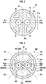
- Fig. 2 is a cross-sectional view showing the support member.
- the support member 60 includes a bottom portion 61, a wall portion 62, support holes 63, and through-holes 64 (see Fig. 2 ).
- the bottom portion 61 is formed in a circular shape as shown in Fig. 2 .
- the wall portion 62 extends vertically upward from an outer edge 61a of the bottom portion 61. That is, the support member 60 is formed in a bowl-like shape by the bottom portion 61 and the wall portion 62.
- the wall portion 62 and the outer edge 61a of the support member 60 are fixed to an inner wall of the container body 50 through, for example, welding. Note that, although the position of the support member 60 in a height direction in the container body 50 may be any position as long as the first pipe 511 and the second pipe 512 can be appropriately supported, in a case where the container body 50 is divided into a plurality of parts at any position in the vertical direction, it is preferable that the support member 60 is provided at a joint therebetween.
- the support holes 63 are through-holes formed in the bottom portion 61 as shown in Figs. 1 and 2 .
- the support holes 63 include a first support hole 631 and a second support hole 632.
- the first support hole 631 and the second support hole 632 are formed in the bottom portion 61 at an interval.
- the first support hole 631 is formed such that the inner diameter thereof becomes slightly larger than the outer diameter of the first pipe 511.
- the first pipe 511 is inserted into the first support hole 631 such that the first pipe 511 is supported in the container body 50.
- the second support hole 632 is formed such that the inner diameter thereof becomes slightly larger than the outer diameter of the second pipe 512. As shown in Fig.
- the second pipe 512 is inserted into the second support hole 632 such that the second pipe 512 is supported in the container body 50.
- the first pipe 511 and the second pipe 512 are supported by the support member 60 and thus the first pipe 511 and the second pipe 512 are restrained from vibrating inside the container body 50 and coming into contact with each other while generating noise.
- a plurality of through-holes 64 are formed at different positions from the first support hole 631 and the second support hole 632 of the bottom portion 61.
- the plurality of through-holes 64 are hole portions provided such that the refrigerant gas, the lubricant L, or the like in the container body 50 flow therethrough and prevent the volume of the accumulator 5 from being reduced because of the support member 60.
- the plurality of through-holes 64 are disposed at positions symmetrical with respect to a center (center of bottom portion 61) 60a of the support member 60.
- an exciting force caused by magnetism of the drive unit 3 driving the compressor body 4 or an exciting force caused by pulsation of the compressor body 4 acts on the accumulator 5 via the connecting member (not shown) that connects the first pipe 511, the second pipe 512, the housing 2, and the container body 50 to each other.
- the exciting force caused by pulsation of the compressor body 4 may cause vibration of a pipe in the accumulator 5 and the vibration may be transmitted to the accumulator 5 via the support member 60, which may cause noise.
- a center 631a of the first support hole 631 and a center 632a of the second support hole 632 formed in the support member 60 are positioned away from a center line A1 passing through the center 60a of the support member 60 as shown in Fig. 2 .
- the center line A1 is a straight line passing through the center 60a along a direction D of the most dominant exciting force from among exciting forces that are transmitted to the first pipe 511 and the second pipe 512 due to pulsation caused by the operation of the compressor body 4, the direction D being shown by a solid arrow in Fig. 2 .
- Being positioned away from the center line A1 means that the center 631a of the first support hole 631 and the center 632a of the second support hole 632 are disposed at positions (positions separated from center line A1) that do not coincide with the center line A1. Accordingly, when the most dominant exciting force caused by pulsation of the compressor body 4 acts on the first pipe 511 and the second pipe 512 along the direction D, a portion of the most dominant exciting force transmitted from the first pipe 511 and the second pipe 512 to the support member 60 is dispersed in a direction in which the support member 60 is twisted with respect to the center 60a.
- the accumulator 5 and the compressor for air conditioning 1 in the present embodiment it is possible to suppress vibration generated in the accumulator 5 provided adjacent to the compressor body 4 of the compressor for air conditioning 1 and to reduce noise generated in the compressor for air conditioning 1.
- the plurality of pipes 51 (first pipe 511 and second pipe 512) are disposed in the container body 50 to correspond to the number of compression chambers 412 and 422 of the compressor body 4, the plurality of support holes 63 (first support hole 631 and second support hole 632) are provided to correspond to the pipes 51, and all of the centers of the support holes 63 (center 631a of first support hole 631 and center 632a of second support hole 632) are positioned away from the center line A1.
- FIG. 3 is a cross-sectional view showing a modification example of the support member.
- a support member 600 shown in Fig. 3 includes a plurality of through-holes 640 instead of the plurality of through-holes 64 of the support member 60 shown in Fig. 2 . Since other constituent elements of the support member 600 are the same as those of the support member 60, the constituent elements are denoted by the same reference numerals and description thereof will be omitted.
- the plurality of through-holes 640 include a pair of large-diameter holes 641 and 642 and a pair of small-diameter holes 643 and 644, in the present embodiment.
- the pair of large-diameter holes 641 and 642 are disposed with the center 60a interposed therebetween in the vertical direction in the drawing.
- the pair of small-diameter holes 643 and 644 are disposed with the center 60a interposed therebetween in the lateral direction in the drawing.
- the shapes and the positions of the through-holes 64 and 640 shown in Figs. 2 and 3 are merely examples and if the first support hole 631 and the second support hole 632 are formed at different positions, various shapes and positions corresponding to a performance required for the accumulator 5 can be adopted.
- a rib portion 65 extends from the outer edge 61a between the through-holes 640 of the support member 600 that are adjacent to each other.
- the rib portions 65 include rib portions 651, 652, 653, and 654 as shown in the drawing.
- the rib portion 651 is a portion that extends between the large-diameter hole 641 and the small-diameter hole 643.
- the rib portion 652 is a portion that extends between the large-diameter hole 641 and the small-diameter hole 644.
- the rib portion 653 is a portion that extends between the large-diameter hole 642 and the small-diameter hole 643.
- the rib portion 654 is a portion that extends between the large-diameter hole 642 and the small-diameter hole 644.
- two-dot chain lines in Fig. 3 show a center line B1 along an extending direction of the rib portion 651, a center line B2 along an extending direction of the rib portion 652, a center line B3 along an extending direction of the rib portion 653, and a center line B4 along an extending direction of the rib portion 654, respectively.
- the "extending directions" are directions in which the rib portions 651, 652, 653, and 654 extend toward the center 60a of the support member 600 from the outer edge 61a.
- the center 631a of the first support hole 631 and the center 632a of the second support hole 632 are positioned away from the center lines B1, B2, B3, and B4 as shown in the drawing.
- Being positioned away from the center lines B1, B2, B3, and B4" means that the center 631a of the first support hole 631 and the center 632a of the second support hole 632 are disposed at positions (positions separated from center lines B1, B2, B3, and B4) that do not coincide with the center lines B1, B2, B3, and B4.
- the shapes of the support members 60 and 600 are not limited to those in the present embodiment.
- the support members 60 and 600 may include no wall portion 62 as long as the support members 60 and 600 can be stably fixed to the container body 50.
- a configuration in which the support members 60 and 600 are provided with cylindrical portions that protrude in at least any one of vertical directions from edge portions of the first support hole 631 and the second support hole 632 and the cylindrical portions widely support outer peripheries of the first pipe 511 and the second pipe 512 may also be adopted.
- the bottom portions 61 of the support members 60 and 600 may be formed in a shape other than a circular shape to correspond to the shape of an inner surface of the container body 50.
- a configuration of the accumulator 5 according to the embodiment has been described with the twin rotary type compressor for air conditioning 1 as a target.
- the accumulator 5 according to the embodiment may be applied to any compressor for air conditioning such as a single rotary type compressor for air conditioning or a scroll type compressor for air conditioning.
- the support member 60 may include one support hole 63 for supporting the one pipe 51.
- the center of the support hole 63 may be positioned away from at least the center line A1 shown in Fig. 2 and more preferably positioned away from the center lines B1, B2, B3, and B4 shown in Fig. 3 .
- the support member 60 may include three or more support holes 63 to correspond to the number of the plurality of pipes 51.
- the centers of the three or more support holes 63 may be positioned away from at least the center line A1 shown in Fig. 2 and more preferably positioned away from the center lines B1, B2, B3, and B4 shown in Fig. 3 .
Landscapes
- Engineering & Computer Science (AREA)
- Mechanical Engineering (AREA)
- General Engineering & Computer Science (AREA)
- Chemical & Material Sciences (AREA)
- Analytical Chemistry (AREA)
- Power Engineering (AREA)
- Physics & Mathematics (AREA)
- Thermal Sciences (AREA)
- Compressor (AREA)
- Applications Or Details Of Rotary Compressors (AREA)
Abstract
Description
- The present invention relates to an accumulator and a compressor for air conditioning.
- In the related art, there is a known technique related to an accumulator for separating a refrigerant gas from lubricant, a foreign substance, or the like through gas-liquid separation and supplying the refrigerant gas to a compressor body in a compressor for air conditioning. For example,
PTL 1 discloses a structure in which a pipe for supplying a refrigerant gas from an accumulator to a compressor body is supported by a support member (connecting member) provided in the accumulator. - [PTL 1] Japanese Unexamined Patent Application Publication No.
2011-169183 - In a case where the accumulator as described in
PTL 1 is provided adjacent to the compressor body, an exciting force caused by magnetism of a motor driving the compressor body or an exciting force caused by pulsation of the compressor body acts thereon. Particularly, the exciting force caused by pulsation of the compressor body may cause vibration of a pipe in the accumulator and the vibration may be transmitted to the accumulator via the support member, which may cause noise. - The present invention has been made in view of such circumstances and an object thereof is to suppress vibration generated in an accumulator provided adjacent to a compressor body of a compressor for air conditioning and to reduce noise generated in the compressor for air conditioning.
- In order to solve the above-described problems and achieve the object, according to the present invention, there is provided an accumulator which is provided adjacent to a compressor body of a compressor for air conditioning and which supplies a refrigerant gas subjected to gas-liquid separation from a container body to the compressor body via a pipe. The accumulator includes a support member of which an outer edge is attached to an inner wall of the container body, the support member including a support hole that supports the pipe inside the container body and a center of the support hole is positioned away from a center line that passes through a center of the support member along a direction of a most dominant exciting force transmitted from the compressor body.
- According to the configuration, a portion of the most dominant exciting force transmitted from the pipe to the support member is dispersed in a direction in which the support member is twisted. As a result, an exciting force that is transmitted to the container body of the accumulator from the pipe via the support member can be reduced. Therefore, according to the accumulator in the present invention, vibration generated at the accumulator provided adjacent to the compressor body of the compressor for air conditioning can be suppressed and noise generated at the compressor for air conditioning can be reduced.
- In addition, it is preferable that the support member includes a plurality of through-holes provided at positions different from the support hole, a rib portion extending from the outer edge extends between the through-holes of the support member that are adjacent to each other, and the center of the support hole is positioned away from a center line along an extending direction in which the rib portion extends toward the center of the support member from the outer edge.
- According to the configuration, regardless of the direction of the exciting force transmitted from the compressor body, a portion of an exciting force transmitted from the pipe to the rib portion is dispersed in a direction in which the rib portion is twisted. As a result, an exciting force that is transmitted from the pipe to the container body of the accumulator via the rib portion of the support member can be reduced and vibration generated at the accumulator can be suppressed.
- In addition, it is preferable that a plurality of the pipes are disposed in the container body to correspond to the number of compression chambers of the compressor body, a plurality of the support holes are provided to correspond to the disposed plurality of pipes, and all of centers of the support holes are positioned away from the center line.
- According to the configuration, even in a case where there are a plurality of the pipes, an exciting force that is transmitted from each of the pipes to the container body of the accumulator via the support member can be reduced and vibration generated at the accumulator can be suppressed.
- In order to solve the above-described problems and achieve the object, according to the present invention, there is provided a compressor for air conditioning including the accumulator described above and the compressor body to which the refrigerant gas is supplied from the accumulator via the pipe.
- According to the configuration, it is possible to suppress vibration generated in the accumulator provided adjacent to the compressor body of the compressor for air conditioning and to reduce noise generated in the compressor for air conditioning.
-
-
Fig. 1 is a schematic view showing an accumulator and a compressor for air conditioning according to an embodiment. -
Fig. 2 is a cross-sectional view showing a support member. -
Fig. 3 is a cross-sectional view showing a modification example of the support member. - Hereinafter, an embodiment of an accumulator and a compressor for air conditioning according to the present invention will be described in detail based on the drawings. Note that, the present invention is not limited by the embodiment.
- The compressor for
air conditioning 1 according to the embodiment is applied to, for example, an air conditioner for a room. Although not explicitly shown in the drawings, the air conditioner is configured to include an outdoor unit disposed outdoors and an indoor unit disposed indoors. The air conditioner circulates a refrigerant between the outdoor unit and the indoor unit and performs heat exchange outdoors and indoors to perform cooling, heating, or cooling and heating indoors. In the air conditioner, the compressor forair conditioning 1 is disposed in the outdoor unit, sucks and compresses a refrigerant, and supplies the refrigerant to the outdoor unit or an external element of the indoor unit. Note that, the compressor forair conditioning 1 is not limited to an air conditioner for a room and may be applied to an air conditioner having any use. - As shown in
Fig. 1 , the compressor forair conditioning 1 is configured to include ahousing 2, adrive unit 3, acompressor body 4, and anaccumulator 5. - The
housing 2 has a substantially cylindrical shape of which a top and a bottom are sealed and thedrive unit 3 and thecompressor body 4 are accommodated therein. Thehousing 2 is disposed with a cylinder thereof standing upright and adischarge pipe 21 is provided at a top thereof. In addition, a bottom portion of thehousing 2 is configured as anoil reservoir 22 and lubricant L to be supplied to thecompressor body 4 is stored in theoil reservoir 22. - The
drive unit 3 is a slot motor and includes astator 31, arotor 32, and ashaft 33. Thedrive unit 3 is fixed to an inner wall surface of thehousing 2 at thestator 31. Therotor 32 is provided to be rotatable with respect to thestator 31 and theshaft 33 is provided to face a vertically lower side. A lower end portion of theshaft 33 is connected to thecompressor body 4. Power is supplied to thedrive unit 3 from the outside of thehousing 2 via a wire (not shown). - The
compressor body 4 is disposed below thedrive unit 3 inside thehousing 2. In the present embodiment, thecompressor body 4 is a two-cylinder twin rotary type compression mechanism. In thecompressor body 4, afirst compression section 41 and asecond compression section 42 are configured in multiple stages arranged vertically. Thefirst compression section 41 and thesecond compression section 42 are arranged along the axis of rotation of theshaft 33. Thefirst compression section 41 includes arotor 411 and acompression chamber 412. Thesecond compression section 42 includes arotor 421 and acompression chamber 422. Apartition plate 43 is provided between thefirst compression section 41 and thesecond compression section 42. Thepartition plate 43 constitutes a portion of the walls of thecompression chambers insertion hole 431 into which theshaft 33 is inserted is formed in thepartition plate 43.Bearings 44 are provided above and below thefirst compression section 41 and thesecond compression section 42. Thebearings 44 rotatably support theshaft 33. Regarding theshaft 33, acrank 331 is provided at a position corresponding to thefirst compression section 41 and acrank 332 is provided at a position corresponding to thesecond compression section 42. Thecrank 331 is provided with therotor 411 and thecrank 332 is provided with therotor 421. - In addition, inside the lower end portion of the
shaft 33, anoil supply passage 333 is provided. A lower end of theshaft 33 is provided to reach theoil reservoir 22 of thehousing 2 and from the lower end, the lubricant L is supplied to thecompressor body 4 via theoil supply passage 333. Note that, theoil supply passage 333 includes anoil supply passage 333a penetrating thecrank 331 corresponding to thefirst compression section 41 and anoil supply passage 333b penetrating thecrank 332 corresponding to thesecond compression section 42. - The
accumulator 5 is a separator performing gas-liquid separation of a refrigerant gas as a working fluid. Theaccumulator 5 is disposed outside thehousing 2 while being disposed adjacent to the compressor body 4 (adjacent to housing 2). Theaccumulator 5 includes acontainer body 50, a plurality ofpipes 51, and asupport member 60. - The
container body 50 has a substantially cylindrical shape of which a top and a bottom are sealed. Thecontainer body 50 is connected to thehousing 2 via a connecting member (not shown). A top of thecontainer body 50 is provided with aninflow pipe 501. Thepipes 51 include afirst pipe 511 and asecond pipe 512. Thefirst pipe 511 and thesecond pipe 512 extend toward the top portion from a bottom portion of thecontainer body 50, inside thecontainer body 50. One end of thefirst pipe 511 is connected to thecompression chamber 412 of thefirst compression section 41 and the other end thereof is open inside thecontainer body 50. In addition, thefirst pipe 511 is supported by thesupport member 60 which will be described later. Thesecond pipe 512 is a pipe for supplying a fluid to thesecond compression section 42 of thecompressor body 4. One end of thesecond pipe 512 is connected to thecompression chamber 422 of thesecond compression section 42 and the other end thereof is open inside thecontainer body 50. In addition, thesecond pipe 512 is supported by thesupport member 60 which will be described later. - In the case of the compressor for
air conditioning 1 configured as described above, a refrigerant gas that has passed through an external element (for example, evaporator (not shown)) is supplied into thecontainer body 50 of theaccumulator 5 via theinflow pipe 501. Furthermore, the refrigerant gas is supplied to thefirst compression section 41 of thecompressor body 4 via thefirst pipe 511 and is supplied to thesecond compression section 42 of thecompressor body 4 via thesecond pipe 512. In thecompressor body 4, when power is supplied to thedrive unit 3 and theshaft 33 is rotated, therotors compression chambers cranks compression chambers compression chambers housing 2 from thedischarge pipe 21 and is supplied to the external element. - In addition, as described above, into each of the
compression chambers compression chambers accumulator 5, the lubricant L or dust is separated from the refrigerant gas that has passed through the external element through gas-liquid separation by means of a net-shapedfilter 53 provided at an upper portion of thecontainer body 50. Regarding theaccumulator 5, the refrigerant gas subjected to the gas-liquid separation is supplied to thecompression chambers container body 50. Note that, theaccumulator 5 is configured such that anoil return hole 511a is formed in thefirst pipe 511, anoil return hole 512a is formed in thesecond pipe 512, and the lubricant L accumulated on the bottom portion of thecontainer body 50 is returned to thecompression chambers - Next, the
support member 60 included in theaccumulator 5 according to the present embodiment will be described in detail with reference toFigs. 1 and2. Fig. 2 is a cross-sectional view showing the support member. As shown inFig. 1 , thesupport member 60 includes abottom portion 61, awall portion 62, support holes 63, and through-holes 64 (seeFig. 2 ). Thebottom portion 61 is formed in a circular shape as shown inFig. 2 . Thewall portion 62 extends vertically upward from anouter edge 61a of thebottom portion 61. That is, thesupport member 60 is formed in a bowl-like shape by thebottom portion 61 and thewall portion 62. Thewall portion 62 and theouter edge 61a of thesupport member 60 are fixed to an inner wall of thecontainer body 50 through, for example, welding. Note that, although the position of thesupport member 60 in a height direction in thecontainer body 50 may be any position as long as thefirst pipe 511 and thesecond pipe 512 can be appropriately supported, in a case where thecontainer body 50 is divided into a plurality of parts at any position in the vertical direction, it is preferable that thesupport member 60 is provided at a joint therebetween. - The support holes 63 are through-holes formed in the
bottom portion 61 as shown inFigs. 1 and2 . The support holes 63 include afirst support hole 631 and asecond support hole 632. Thefirst support hole 631 and thesecond support hole 632 are formed in thebottom portion 61 at an interval. Thefirst support hole 631 is formed such that the inner diameter thereof becomes slightly larger than the outer diameter of thefirst pipe 511. As shown inFig. 1 , thefirst pipe 511 is inserted into thefirst support hole 631 such that thefirst pipe 511 is supported in thecontainer body 50. Thesecond support hole 632 is formed such that the inner diameter thereof becomes slightly larger than the outer diameter of thesecond pipe 512. As shown inFig. 1 , thesecond pipe 512 is inserted into thesecond support hole 632 such that thesecond pipe 512 is supported in thecontainer body 50. As described above, thefirst pipe 511 and thesecond pipe 512 are supported by thesupport member 60 and thus thefirst pipe 511 and thesecond pipe 512 are restrained from vibrating inside thecontainer body 50 and coming into contact with each other while generating noise. - As shown in
Fig. 2 , a plurality of through-holes 64 are formed at different positions from thefirst support hole 631 and thesecond support hole 632 of thebottom portion 61. The plurality of through-holes 64 are hole portions provided such that the refrigerant gas, the lubricant L, or the like in thecontainer body 50 flow therethrough and prevent the volume of theaccumulator 5 from being reduced because of thesupport member 60. In the present embodiment, the plurality of through-holes 64 are disposed at positions symmetrical with respect to a center (center of bottom portion 61) 60a of thesupport member 60. - Here, in a case where the
accumulator 5 is provided adjacent to the compressor body 4 (adjacent to housing 2) as with the compressor forair conditioning 1 according to the present embodiment, an exciting force caused by magnetism of thedrive unit 3 driving thecompressor body 4 or an exciting force caused by pulsation of thecompressor body 4 acts on theaccumulator 5 via the connecting member (not shown) that connects thefirst pipe 511, thesecond pipe 512, thehousing 2, and thecontainer body 50 to each other. Particularly, the exciting force caused by pulsation of thecompressor body 4 may cause vibration of a pipe in theaccumulator 5 and the vibration may be transmitted to theaccumulator 5 via thesupport member 60, which may cause noise. - Therefore, in the present embodiment, a
center 631a of thefirst support hole 631 and acenter 632a of thesecond support hole 632 formed in thesupport member 60 are positioned away from a center line A1 passing through thecenter 60a of thesupport member 60 as shown inFig. 2 . The center line A1 is a straight line passing through thecenter 60a along a direction D of the most dominant exciting force from among exciting forces that are transmitted to thefirst pipe 511 and thesecond pipe 512 due to pulsation caused by the operation of thecompressor body 4, the direction D being shown by a solid arrow inFig. 2 . "Being positioned away from the center line A1" means that thecenter 631a of thefirst support hole 631 and thecenter 632a of thesecond support hole 632 are disposed at positions (positions separated from center line A1) that do not coincide with the center line A1. Accordingly, when the most dominant exciting force caused by pulsation of thecompressor body 4 acts on thefirst pipe 511 and thesecond pipe 512 along the direction D, a portion of the most dominant exciting force transmitted from thefirst pipe 511 and thesecond pipe 512 to thesupport member 60 is dispersed in a direction in which thesupport member 60 is twisted with respect to thecenter 60a. As a result, an exciting force that is transmitted to thecontainer body 50 of theaccumulator 5 from thefirst pipe 511 and thesecond pipe 512 via theouter edge 61a of thesupport member 60 is reduced and vibration of thecontainer body 50 is suppressed. Therefore, generation of noise in the compressor forair conditioning 1 is suppressed. - As described above, according to the
accumulator 5 and the compressor forair conditioning 1 in the present embodiment, it is possible to suppress vibration generated in theaccumulator 5 provided adjacent to thecompressor body 4 of the compressor forair conditioning 1 and to reduce noise generated in the compressor forair conditioning 1. - In addition, the plurality of pipes 51 (
first pipe 511 and second pipe 512) are disposed in thecontainer body 50 to correspond to the number ofcompression chambers compressor body 4, the plurality of support holes 63 (first support hole 631 and second support hole 632) are provided to correspond to thepipes 51, and all of the centers of the support holes 63 (center 631a offirst support hole 631 andcenter 632a of second support hole 632) are positioned away from the center line A1. - According to the configuration, even in a case where there are a plurality of the
pipes 51, an exciting force that is transmitted from each of the pipes 51 (first pipe 511 and second pipe 512) to thecontainer body 50 of theaccumulator 5 via thesupport member 60 can be reduced and vibration generated at theaccumulator 5 can be suppressed. -
Fig. 3 is a cross-sectional view showing a modification example of the support member. Asupport member 600 shown inFig. 3 includes a plurality of through-holes 640 instead of the plurality of through-holes 64 of thesupport member 60 shown inFig. 2 . Since other constituent elements of thesupport member 600 are the same as those of thesupport member 60, the constituent elements are denoted by the same reference numerals and description thereof will be omitted. - The plurality of through-
holes 640 include a pair of large-diameter holes diameter holes 643 and 644, in the present embodiment. The pair of large-diameter holes center 60a interposed therebetween in the vertical direction in the drawing. The pair of small-diameter holes 643 and 644 are disposed with thecenter 60a interposed therebetween in the lateral direction in the drawing. Note that, the shapes and the positions of the through-holes Figs. 2 and 3 are merely examples and if thefirst support hole 631 and thesecond support hole 632 are formed at different positions, various shapes and positions corresponding to a performance required for theaccumulator 5 can be adopted. - Accordingly, a rib portion 65 extends from the
outer edge 61a between the through-holes 640 of thesupport member 600 that are adjacent to each other. The rib portions 65 includerib portions rib portion 651 is a portion that extends between the large-diameter hole 641 and the small-diameter hole 643. Therib portion 652 is a portion that extends between the large-diameter hole 641 and the small-diameter hole 644. Therib portion 653 is a portion that extends between the large-diameter hole 642 and the small-diameter hole 643. Therib portion 654 is a portion that extends between the large-diameter hole 642 and the small-diameter hole 644. - Here, two-dot chain lines in
Fig. 3 show a center line B1 along an extending direction of therib portion 651, a center line B2 along an extending direction of therib portion 652, a center line B3 along an extending direction of therib portion 653, and a center line B4 along an extending direction of therib portion 654, respectively. The "extending directions" are directions in which therib portions center 60a of thesupport member 600 from theouter edge 61a. In thesupport member 600, thecenter 631a of thefirst support hole 631 and thecenter 632a of thesecond support hole 632 are positioned away from the center lines B1, B2, B3, and B4 as shown in the drawing. "Being positioned away from the center lines B1, B2, B3, and B4" means that thecenter 631a of thefirst support hole 631 and thecenter 632a of thesecond support hole 632 are disposed at positions (positions separated from center lines B1, B2, B3, and B4) that do not coincide with the center lines B1, B2, B3, and B4. - According to the configuration, regardless of the direction of an exciting force transmitted from the
compressor body 4, a portion of an exciting force transmitted from thefirst pipe 511 and thesecond pipe 512 to therib portions rib portions first pipe 511 and thesecond pipe 512 to thecontainer body 50 of theaccumulator 5 via therib portions support member 600 can be reduced and vibration generated at theaccumulator 5 can be suppressed. - Note that, the shapes of the
support members support members wall portion 62 as long as thesupport members container body 50. In addition, a configuration in which thesupport members first support hole 631 and thesecond support hole 632 and the cylindrical portions widely support outer peripheries of thefirst pipe 511 and thesecond pipe 512 may also be adopted. In addition, in a case where thecontainer body 50 does not have a substantially cylindrical shape, thebottom portions 61 of thesupport members container body 50. - In the present embodiment, a configuration of the
accumulator 5 according to the embodiment has been described with the twin rotary type compressor forair conditioning 1 as a target. However, theaccumulator 5 according to the embodiment may be applied to any compressor for air conditioning such as a single rotary type compressor for air conditioning or a scroll type compressor for air conditioning. - For example, in the case of a configuration in which the
compressor body 4 includes only one compression chamber and there is only onepipe 51 connecting theaccumulator 5 and the compression chamber to each other, thesupport member 60 may include onesupport hole 63 for supporting the onepipe 51. In this case as well, the center of thesupport hole 63 may be positioned away from at least the center line A1 shown inFig. 2 and more preferably positioned away from the center lines B1, B2, B3, and B4 shown inFig. 3 . - In addition, for example, in the case of a configuration in which the
compressor body 4 includes three or more compression chambers and there is three ormore pipes 51 connecting theaccumulator 5 and the compression chambers to each other, thesupport member 60 may include three or more support holes 63 to correspond to the number of the plurality ofpipes 51. In this case as well, the centers of the three or more support holes 63 may be positioned away from at least the center line A1 shown inFig. 2 and more preferably positioned away from the center lines B1, B2, B3, and B4 shown inFig. 3 . -
- 1
- compressor for air conditioning
- 2
- housing
- 21
- discharge pipe
- 22
- oil reservoir
- 3
- drive unit
- 31
- stator
- 32
- rotor
- 33
- shaft
- 331, 332
- crank
- 333, 333a, 333B
- oil supply passage
- 4
- compressor body
- 41
- first compression section
- 411, 421
- rotor
- 412, 422
- compression chamber
- 42
- second compression section
- 43
- partition plate
- 44
- bearing
- 431
- insertion hole
- 5
- accumulator
- 50
- container body
- 501
- inflow pipe
- 51
- pipe
- 511a, 512a
- oil return hole
- 511
- first pipe
- 512
- second pipe
- 53
- filter
- 60, 600
- support member
- 60a, 631a, 632a
- center
- 61a
- outer edge
- 61
- bottom portion
- 62
- wall portion
- 63
- support hole
- 64, 640
- through-hole
- 65
- rib portion
- 631
- first support hole
- 632
- second support hole
- 641, 642
- large-diameter hole
- 643, 644
- small-diameter hole
- 651, 652, 653, 654
- rib portion
- A1, B1, B2, B3, B4
- center line
- L
- lubricant
Claims (4)
- An accumulator which is provided adjacent to a compressor body of a compressor for air conditioning and which supplies a refrigerant gas subjected to gas-liquid separation from a container body to the compressor body via a pipe, the accumulator comprising:a support member of which an outer edge is attached to an inner wall of the container body, the support member including a support hole that supports the pipe inside the container body,wherein a center of the support hole is positioned away from a center line that passes through a center of the support member along a direction of a most dominant exciting force transmitted from the compressor body.
- The accumulator according to Claim 1,
wherein the support member includes a plurality of through-holes provided at positions different from the support hole,
wherein a rib portion extending from the outer edge extends between the through-holes of the support member that are adjacent to each other, and
wherein the center of the support hole is positioned away from a center line along an extending direction in which the rib portion extends toward the center of the support member from the outer edge. - The accumulator according to any one of Claims 1 to Claim 2,
wherein a plurality of the pipes are disposed in the container body to correspond to the number of compression chambers of the compressor body,
wherein a plurality of the support holes are provided to correspond to the disposed plurality of pipes, and
wherein all of centers of the support holes are positioned away from the center line. - An compressor for air conditioning comprising:the accumulator according to any one of Claims 1 to 3; andthe compressor body to which the refrigerant gas is supplied from the accumulator via the pipe.
Applications Claiming Priority (2)
| Application Number | Priority Date | Filing Date | Title |
|---|---|---|---|
| JP2018023105A JP2019138576A (en) | 2018-02-13 | 2018-02-13 | Accumulator, and compressor for air conditioning |
| PCT/JP2018/044426 WO2019159497A1 (en) | 2018-02-13 | 2018-12-03 | Accumulator, and compressor for air conditioning |
Publications (4)
| Publication Number | Publication Date |
|---|---|
| EP3754270A1 true EP3754270A1 (en) | 2020-12-23 |
| EP3754270A4 EP3754270A4 (en) | 2021-11-17 |
| EP3754270C0 EP3754270C0 (en) | 2024-01-24 |
| EP3754270B1 EP3754270B1 (en) | 2024-01-24 |
Family
ID=67619933
Family Applications (1)
| Application Number | Title | Priority Date | Filing Date |
|---|---|---|---|
| EP18906496.7A Active EP3754270B1 (en) | 2018-02-13 | 2018-12-03 | Accumulator, and compressor for air conditioning |
Country Status (5)
| Country | Link |
|---|---|
| EP (1) | EP3754270B1 (en) |
| JP (1) | JP2019138576A (en) |
| CN (1) | CN212778059U (en) |
| ES (1) | ES2969941T3 (en) |
| WO (1) | WO2019159497A1 (en) |
Cited By (2)
| Publication number | Priority date | Publication date | Assignee | Title |
|---|---|---|---|---|
| CN111794971A (en) * | 2020-07-07 | 2020-10-20 | 珠海格力节能环保制冷技术研究中心有限公司 | Liquid storage device and compressor |
| EP4524398A4 (en) * | 2022-07-29 | 2025-06-11 | Daikin Industries, Ltd. | COMPRESSOR AND REFRIGERATION DEVICE |
Families Citing this family (1)
| Publication number | Priority date | Publication date | Assignee | Title |
|---|---|---|---|---|
| JP7504211B2 (en) * | 2020-03-12 | 2024-06-21 | 浙江盾安人工環境股▲ふん▼有限公司 | Gas-liquid separator |
Family Cites Families (10)
| Publication number | Priority date | Publication date | Assignee | Title |
|---|---|---|---|---|
| JPS6019989Y2 (en) * | 1979-09-03 | 1985-06-15 | 株式会社東芝 | rotary compressor |
| JPH0526444Y2 (en) * | 1987-08-03 | 1993-07-05 | ||
| JP3328952B2 (en) * | 1992-05-22 | 2002-09-30 | 松下電器産業株式会社 | Hermetic electric compressor |
| JPH08128746A (en) * | 1994-09-05 | 1996-05-21 | Sanyo Electric Co Ltd | Air conditioner |
| JP2006299943A (en) * | 2005-04-21 | 2006-11-02 | Matsushita Electric Ind Co Ltd | Accumulator for multi-cylinder compressor |
| JP2011169183A (en) | 2010-02-17 | 2011-09-01 | Panasonic Corp | Accumulator for hermetic compressor |
| KR101109634B1 (en) * | 2011-12-16 | 2012-01-31 | 인제대학교 산학협력단 | Accumulator with Heat Exchanger |
| JP5958621B2 (en) * | 2014-08-22 | 2016-08-02 | ダイキン工業株式会社 | accumulator |
| CN205373177U (en) * | 2016-02-22 | 2016-07-06 | 青岛开拓隆海制冷配件有限公司 | Reservoir of proportionable oil return control |
| CN206037515U (en) * | 2016-08-26 | 2017-03-22 | 广东美芝精密制造有限公司 | A compressor that is used for reservoir of compressor and has it |
-
2018
- 2018-02-13 JP JP2018023105A patent/JP2019138576A/en active Pending
- 2018-12-03 WO PCT/JP2018/044426 patent/WO2019159497A1/en not_active Ceased
- 2018-12-03 ES ES18906496T patent/ES2969941T3/en active Active
- 2018-12-03 EP EP18906496.7A patent/EP3754270B1/en active Active
- 2018-12-03 CN CN201890001531.4U patent/CN212778059U/en active Active
Cited By (2)
| Publication number | Priority date | Publication date | Assignee | Title |
|---|---|---|---|---|
| CN111794971A (en) * | 2020-07-07 | 2020-10-20 | 珠海格力节能环保制冷技术研究中心有限公司 | Liquid storage device and compressor |
| EP4524398A4 (en) * | 2022-07-29 | 2025-06-11 | Daikin Industries, Ltd. | COMPRESSOR AND REFRIGERATION DEVICE |
Also Published As
| Publication number | Publication date |
|---|---|
| CN212778059U (en) | 2021-03-23 |
| WO2019159497A1 (en) | 2019-08-22 |
| EP3754270C0 (en) | 2024-01-24 |
| ES2969941T3 (en) | 2024-05-23 |
| JP2019138576A (en) | 2019-08-22 |
| EP3754270B1 (en) | 2024-01-24 |
| EP3754270A4 (en) | 2021-11-17 |
Similar Documents
| Publication | Publication Date | Title |
|---|---|---|
| JP5346210B2 (en) | Hermetic rotary compressor and refrigeration cycle apparatus | |
| EP3754270B1 (en) | Accumulator, and compressor for air conditioning | |
| CN102725526A (en) | Compressors and Freezers | |
| JP2005146987A (en) | Heat exchanger integral type horizontal compressor with built-in accumulator | |
| KR100612811B1 (en) | Horizontal Rotary Compressor | |
| CN110662902A (en) | Sealed refrigeration compressor and refrigerating device | |
| CN105114315A (en) | Multi-cylinder rotating type compressor | |
| CN205036583U (en) | Rotary compressor | |
| WO2016139873A1 (en) | Compressor | |
| AU2020101791A4 (en) | Accumulator and compressor for air conditioning | |
| WO2022085443A1 (en) | Compressor and refrigeration cycle device | |
| JP2005146986A (en) | Heat exchanger integral type compressor with built-in accumulator | |
| KR102089805B1 (en) | Rotary compressor and manufacturing method of rotary compressor | |
| CN205036580U (en) | Multi -cylinder rotary compressor | |
| JP6710348B1 (en) | Compressor and air conditioner equipped with this compressor | |
| US8556598B2 (en) | Sealed compressor with multiple compressor unit | |
| CN111287974B (en) | Four-cylinder compressor and refrigerating device with same | |
| JP4720649B2 (en) | Electric compressor | |
| JP2009108747A (en) | Hermetic electric compressor | |
| KR101990137B1 (en) | Accumulator and Compression Unit including the same | |
| JP6753355B2 (en) | Scroll compressor | |
| JP6772934B2 (en) | Electric compressor | |
| JP2615885B2 (en) | Horizontal scroll compressor | |
| CN104948466A (en) | Rotary compressor and refrigeration cycle device provided with the same | |
| EP3936721B1 (en) | Compressor and tool |
Legal Events
| Date | Code | Title | Description |
|---|---|---|---|
| STAA | Information on the status of an ep patent application or granted ep patent |
Free format text: STATUS: THE INTERNATIONAL PUBLICATION HAS BEEN MADE |
|
| PUAI | Public reference made under article 153(3) epc to a published international application that has entered the european phase |
Free format text: ORIGINAL CODE: 0009012 |
|
| STAA | Information on the status of an ep patent application or granted ep patent |
Free format text: STATUS: REQUEST FOR EXAMINATION WAS MADE |
|
| 17P | Request for examination filed |
Effective date: 20200812 |
|
| AK | Designated contracting states |
Kind code of ref document: A1 Designated state(s): AL AT BE BG CH CY CZ DE DK EE ES FI FR GB GR HR HU IE IS IT LI LT LU LV MC MK MT NL NO PL PT RO RS SE SI SK SM TR |
|
| AX | Request for extension of the european patent |
Extension state: BA ME |
|
| DAV | Request for validation of the european patent (deleted) | ||
| DAX | Request for extension of the european patent (deleted) | ||
| A4 | Supplementary search report drawn up and despatched |
Effective date: 20211015 |
|
| RIC1 | Information provided on ipc code assigned before grant |
Ipc: F04C 29/12 20060101ALI20211011BHEP Ipc: F04B 39/16 20060101ALI20211011BHEP Ipc: F04B 39/12 20060101ALI20211011BHEP Ipc: F04B 39/00 20060101ALI20211011BHEP Ipc: F25B 43/00 20060101AFI20211011BHEP |
|
| REG | Reference to a national code |
Ref country code: DE Ref legal event code: R079 Free format text: PREVIOUS MAIN CLASS: F25B0043000000 Ipc: F04B0039120000 Ref document number: 602018064681 Country of ref document: DE |
|
| GRAP | Despatch of communication of intention to grant a patent |
Free format text: ORIGINAL CODE: EPIDOSNIGR1 |
|
| STAA | Information on the status of an ep patent application or granted ep patent |
Free format text: STATUS: GRANT OF PATENT IS INTENDED |
|
| RIC1 | Information provided on ipc code assigned before grant |
Ipc: F25B 43/00 20060101ALI20230728BHEP Ipc: F04C 29/06 20060101ALI20230728BHEP Ipc: F04C 23/00 20060101ALI20230728BHEP Ipc: F04B 39/16 20060101ALI20230728BHEP Ipc: F04B 39/12 20060101AFI20230728BHEP |
|
| INTG | Intention to grant announced |
Effective date: 20230814 |
|
| GRAS | Grant fee paid |
Free format text: ORIGINAL CODE: EPIDOSNIGR3 |
|
| GRAA | (expected) grant |
Free format text: ORIGINAL CODE: 0009210 |
|
| STAA | Information on the status of an ep patent application or granted ep patent |
Free format text: STATUS: THE PATENT HAS BEEN GRANTED |
|
| AK | Designated contracting states |
Kind code of ref document: B1 Designated state(s): AL AT BE BG CH CY CZ DE DK EE ES FI FR GB GR HR HU IE IS IT LI LT LU LV MC MK MT NL NO PL PT RO RS SE SI SK SM TR |
|
| REG | Reference to a national code |
Ref country code: GB Ref legal event code: FG4D |
|
| REG | Reference to a national code |
Ref country code: CH Ref legal event code: EP |
|
| REG | Reference to a national code |
Ref country code: DE Ref legal event code: R096 Ref document number: 602018064681 Country of ref document: DE |
|
| REG | Reference to a national code |
Ref country code: IE Ref legal event code: FG4D |
|
| U01 | Request for unitary effect filed |
Effective date: 20240201 |
|
| U07 | Unitary effect registered |
Designated state(s): AT BE BG DE DK EE FI FR IT LT LU LV MT NL PT SE SI Effective date: 20240209 |
|
| REG | Reference to a national code |
Ref country code: ES Ref legal event code: FG2A Ref document number: 2969941 Country of ref document: ES Kind code of ref document: T3 Effective date: 20240523 |
|
| PG25 | Lapsed in a contracting state [announced via postgrant information from national office to epo] |
Ref country code: IS Free format text: LAPSE BECAUSE OF FAILURE TO SUBMIT A TRANSLATION OF THE DESCRIPTION OR TO PAY THE FEE WITHIN THE PRESCRIBED TIME-LIMIT Effective date: 20240524 |
|
| PG25 | Lapsed in a contracting state [announced via postgrant information from national office to epo] |
Ref country code: GR Free format text: LAPSE BECAUSE OF FAILURE TO SUBMIT A TRANSLATION OF THE DESCRIPTION OR TO PAY THE FEE WITHIN THE PRESCRIBED TIME-LIMIT Effective date: 20240425 |
|
| PG25 | Lapsed in a contracting state [announced via postgrant information from national office to epo] |
Ref country code: HR Free format text: LAPSE BECAUSE OF FAILURE TO SUBMIT A TRANSLATION OF THE DESCRIPTION OR TO PAY THE FEE WITHIN THE PRESCRIBED TIME-LIMIT Effective date: 20240124 Ref country code: RS Free format text: LAPSE BECAUSE OF FAILURE TO SUBMIT A TRANSLATION OF THE DESCRIPTION OR TO PAY THE FEE WITHIN THE PRESCRIBED TIME-LIMIT Effective date: 20240424 |
|
| PG25 | Lapsed in a contracting state [announced via postgrant information from national office to epo] |
Ref country code: RS Free format text: LAPSE BECAUSE OF FAILURE TO SUBMIT A TRANSLATION OF THE DESCRIPTION OR TO PAY THE FEE WITHIN THE PRESCRIBED TIME-LIMIT Effective date: 20240424 Ref country code: NO Free format text: LAPSE BECAUSE OF FAILURE TO SUBMIT A TRANSLATION OF THE DESCRIPTION OR TO PAY THE FEE WITHIN THE PRESCRIBED TIME-LIMIT Effective date: 20240424 Ref country code: IS Free format text: LAPSE BECAUSE OF FAILURE TO SUBMIT A TRANSLATION OF THE DESCRIPTION OR TO PAY THE FEE WITHIN THE PRESCRIBED TIME-LIMIT Effective date: 20240524 Ref country code: HR Free format text: LAPSE BECAUSE OF FAILURE TO SUBMIT A TRANSLATION OF THE DESCRIPTION OR TO PAY THE FEE WITHIN THE PRESCRIBED TIME-LIMIT Effective date: 20240124 Ref country code: GR Free format text: LAPSE BECAUSE OF FAILURE TO SUBMIT A TRANSLATION OF THE DESCRIPTION OR TO PAY THE FEE WITHIN THE PRESCRIBED TIME-LIMIT Effective date: 20240425 |
|
| PG25 | Lapsed in a contracting state [announced via postgrant information from national office to epo] |
Ref country code: PL Free format text: LAPSE BECAUSE OF FAILURE TO SUBMIT A TRANSLATION OF THE DESCRIPTION OR TO PAY THE FEE WITHIN THE PRESCRIBED TIME-LIMIT Effective date: 20240124 |
|
| PG25 | Lapsed in a contracting state [announced via postgrant information from national office to epo] |
Ref country code: PL Free format text: LAPSE BECAUSE OF FAILURE TO SUBMIT A TRANSLATION OF THE DESCRIPTION OR TO PAY THE FEE WITHIN THE PRESCRIBED TIME-LIMIT Effective date: 20240124 |
|
| PG25 | Lapsed in a contracting state [announced via postgrant information from national office to epo] |
Ref country code: SM Free format text: LAPSE BECAUSE OF FAILURE TO SUBMIT A TRANSLATION OF THE DESCRIPTION OR TO PAY THE FEE WITHIN THE PRESCRIBED TIME-LIMIT Effective date: 20240124 |
|
| PG25 | Lapsed in a contracting state [announced via postgrant information from national office to epo] |
Ref country code: CZ Free format text: LAPSE BECAUSE OF FAILURE TO SUBMIT A TRANSLATION OF THE DESCRIPTION OR TO PAY THE FEE WITHIN THE PRESCRIBED TIME-LIMIT Effective date: 20240124 |
|
| REG | Reference to a national code |
Ref country code: DE Ref legal event code: R097 Ref document number: 602018064681 Country of ref document: DE |
|
| PG25 | Lapsed in a contracting state [announced via postgrant information from national office to epo] |
Ref country code: SK Free format text: LAPSE BECAUSE OF FAILURE TO SUBMIT A TRANSLATION OF THE DESCRIPTION OR TO PAY THE FEE WITHIN THE PRESCRIBED TIME-LIMIT Effective date: 20240124 |
|
| PG25 | Lapsed in a contracting state [announced via postgrant information from national office to epo] |
Ref country code: SM Free format text: LAPSE BECAUSE OF FAILURE TO SUBMIT A TRANSLATION OF THE DESCRIPTION OR TO PAY THE FEE WITHIN THE PRESCRIBED TIME-LIMIT Effective date: 20240124 Ref country code: SK Free format text: LAPSE BECAUSE OF FAILURE TO SUBMIT A TRANSLATION OF THE DESCRIPTION OR TO PAY THE FEE WITHIN THE PRESCRIBED TIME-LIMIT Effective date: 20240124 Ref country code: RO Free format text: LAPSE BECAUSE OF FAILURE TO SUBMIT A TRANSLATION OF THE DESCRIPTION OR TO PAY THE FEE WITHIN THE PRESCRIBED TIME-LIMIT Effective date: 20240124 Ref country code: CZ Free format text: LAPSE BECAUSE OF FAILURE TO SUBMIT A TRANSLATION OF THE DESCRIPTION OR TO PAY THE FEE WITHIN THE PRESCRIBED TIME-LIMIT Effective date: 20240124 |
|
| PLBE | No opposition filed within time limit |
Free format text: ORIGINAL CODE: 0009261 |
|
| STAA | Information on the status of an ep patent application or granted ep patent |
Free format text: STATUS: NO OPPOSITION FILED WITHIN TIME LIMIT |
|
| U20 | Renewal fee for the european patent with unitary effect paid |
Year of fee payment: 7 Effective date: 20241107 |
|
| 26N | No opposition filed |
Effective date: 20241025 |
|
| PG25 | Lapsed in a contracting state [announced via postgrant information from national office to epo] |
Ref country code: MC Free format text: LAPSE BECAUSE OF FAILURE TO SUBMIT A TRANSLATION OF THE DESCRIPTION OR TO PAY THE FEE WITHIN THE PRESCRIBED TIME-LIMIT Effective date: 20240124 |
|
| REG | Reference to a national code |
Ref country code: CH Ref legal event code: PL |
|
| PG25 | Lapsed in a contracting state [announced via postgrant information from national office to epo] |
Ref country code: CH Free format text: LAPSE BECAUSE OF NON-PAYMENT OF DUE FEES Effective date: 20241231 |
|
| PG25 | Lapsed in a contracting state [announced via postgrant information from national office to epo] |
Ref country code: IE Free format text: LAPSE BECAUSE OF NON-PAYMENT OF DUE FEES Effective date: 20241203 |
|
| U20 | Renewal fee for the european patent with unitary effect paid |
Year of fee payment: 8 Effective date: 20251110 |
|
| PGFP | Annual fee paid to national office [announced via postgrant information from national office to epo] |
Ref country code: GB Payment date: 20251030 Year of fee payment: 8 |
|
| PGFP | Annual fee paid to national office [announced via postgrant information from national office to epo] |
Ref country code: TR Payment date: 20251128 Year of fee payment: 8 |
|
| PG25 | Lapsed in a contracting state [announced via postgrant information from national office to epo] |
Ref country code: CY Free format text: LAPSE BECAUSE OF FAILURE TO SUBMIT A TRANSLATION OF THE DESCRIPTION OR TO PAY THE FEE WITHIN THE PRESCRIBED TIME-LIMIT; INVALID AB INITIO Effective date: 20181203 |
|
| PGFP | Annual fee paid to national office [announced via postgrant information from national office to epo] |
Ref country code: ES Payment date: 20260108 Year of fee payment: 8 |