EP3754197A1 - Scroll fluid machine and machining method of scroll member - Google Patents
Scroll fluid machine and machining method of scroll member Download PDFInfo
- Publication number
- EP3754197A1 EP3754197A1 EP19757682.0A EP19757682A EP3754197A1 EP 3754197 A1 EP3754197 A1 EP 3754197A1 EP 19757682 A EP19757682 A EP 19757682A EP 3754197 A1 EP3754197 A1 EP 3754197A1
- Authority
- EP
- European Patent Office
- Prior art keywords
- wall
- machining
- section
- end plate
- tooth bottom
- Prior art date
- Legal status (The legal status is an assumption and is not a legal conclusion. Google has not performed a legal analysis and makes no representation as to the accuracy of the status listed.)
- Granted
Links
Images




Classifications
-
- F—MECHANICAL ENGINEERING; LIGHTING; HEATING; WEAPONS; BLASTING
- F04—POSITIVE - DISPLACEMENT MACHINES FOR LIQUIDS; PUMPS FOR LIQUIDS OR ELASTIC FLUIDS
- F04C—ROTARY-PISTON, OR OSCILLATING-PISTON, POSITIVE-DISPLACEMENT MACHINES FOR LIQUIDS; ROTARY-PISTON, OR OSCILLATING-PISTON, POSITIVE-DISPLACEMENT PUMPS
- F04C18/00—Rotary-piston pumps specially adapted for elastic fluids
- F04C18/02—Rotary-piston pumps specially adapted for elastic fluids of arcuate-engagement type, i.e. with circular translatory movement of co-operating members, each member having the same number of teeth or tooth-equivalents
- F04C18/0207—Rotary-piston pumps specially adapted for elastic fluids of arcuate-engagement type, i.e. with circular translatory movement of co-operating members, each member having the same number of teeth or tooth-equivalents both members having co-operating elements in spiral form
- F04C18/0246—Details concerning the involute wraps or their base, e.g. geometry
- F04C18/0269—Details concerning the involute wraps
- F04C18/0276—Different wall heights
-
- B—PERFORMING OPERATIONS; TRANSPORTING
- B23—MACHINE TOOLS; METAL-WORKING NOT OTHERWISE PROVIDED FOR
- B23F—MAKING GEARS OR TOOTHED RACKS
- B23F15/00—Methods or machines for making gear wheels of special kinds not covered by groups B23F7/00 - B23F13/00
-
- F—MECHANICAL ENGINEERING; LIGHTING; HEATING; WEAPONS; BLASTING
- F04—POSITIVE - DISPLACEMENT MACHINES FOR LIQUIDS; PUMPS FOR LIQUIDS OR ELASTIC FLUIDS
- F04C—ROTARY-PISTON, OR OSCILLATING-PISTON, POSITIVE-DISPLACEMENT MACHINES FOR LIQUIDS; ROTARY-PISTON, OR OSCILLATING-PISTON, POSITIVE-DISPLACEMENT PUMPS
- F04C18/00—Rotary-piston pumps specially adapted for elastic fluids
- F04C18/02—Rotary-piston pumps specially adapted for elastic fluids of arcuate-engagement type, i.e. with circular translatory movement of co-operating members, each member having the same number of teeth or tooth-equivalents
-
- F—MECHANICAL ENGINEERING; LIGHTING; HEATING; WEAPONS; BLASTING
- F04—POSITIVE - DISPLACEMENT MACHINES FOR LIQUIDS; PUMPS FOR LIQUIDS OR ELASTIC FLUIDS
- F04C—ROTARY-PISTON, OR OSCILLATING-PISTON, POSITIVE-DISPLACEMENT MACHINES FOR LIQUIDS; ROTARY-PISTON, OR OSCILLATING-PISTON, POSITIVE-DISPLACEMENT PUMPS
- F04C18/00—Rotary-piston pumps specially adapted for elastic fluids
- F04C18/02—Rotary-piston pumps specially adapted for elastic fluids of arcuate-engagement type, i.e. with circular translatory movement of co-operating members, each member having the same number of teeth or tooth-equivalents
- F04C18/0207—Rotary-piston pumps specially adapted for elastic fluids of arcuate-engagement type, i.e. with circular translatory movement of co-operating members, each member having the same number of teeth or tooth-equivalents both members having co-operating elements in spiral form
- F04C18/0215—Rotary-piston pumps specially adapted for elastic fluids of arcuate-engagement type, i.e. with circular translatory movement of co-operating members, each member having the same number of teeth or tooth-equivalents both members having co-operating elements in spiral form where only one member is moving
-
- F—MECHANICAL ENGINEERING; LIGHTING; HEATING; WEAPONS; BLASTING
- F04—POSITIVE - DISPLACEMENT MACHINES FOR LIQUIDS; PUMPS FOR LIQUIDS OR ELASTIC FLUIDS
- F04C—ROTARY-PISTON, OR OSCILLATING-PISTON, POSITIVE-DISPLACEMENT MACHINES FOR LIQUIDS; ROTARY-PISTON, OR OSCILLATING-PISTON, POSITIVE-DISPLACEMENT PUMPS
- F04C18/00—Rotary-piston pumps specially adapted for elastic fluids
- F04C18/02—Rotary-piston pumps specially adapted for elastic fluids of arcuate-engagement type, i.e. with circular translatory movement of co-operating members, each member having the same number of teeth or tooth-equivalents
- F04C18/0207—Rotary-piston pumps specially adapted for elastic fluids of arcuate-engagement type, i.e. with circular translatory movement of co-operating members, each member having the same number of teeth or tooth-equivalents both members having co-operating elements in spiral form
- F04C18/0246—Details concerning the involute wraps or their base, e.g. geometry
- F04C18/0253—Details concerning the base
-
- F—MECHANICAL ENGINEERING; LIGHTING; HEATING; WEAPONS; BLASTING
- F04—POSITIVE - DISPLACEMENT MACHINES FOR LIQUIDS; PUMPS FOR LIQUIDS OR ELASTIC FLUIDS
- F04C—ROTARY-PISTON, OR OSCILLATING-PISTON, POSITIVE-DISPLACEMENT MACHINES FOR LIQUIDS; ROTARY-PISTON, OR OSCILLATING-PISTON, POSITIVE-DISPLACEMENT PUMPS
- F04C27/00—Sealing arrangements in rotary-piston pumps specially adapted for elastic fluids
-
- F—MECHANICAL ENGINEERING; LIGHTING; HEATING; WEAPONS; BLASTING
- F04—POSITIVE - DISPLACEMENT MACHINES FOR LIQUIDS; PUMPS FOR LIQUIDS OR ELASTIC FLUIDS
- F04C—ROTARY-PISTON, OR OSCILLATING-PISTON, POSITIVE-DISPLACEMENT MACHINES FOR LIQUIDS; ROTARY-PISTON, OR OSCILLATING-PISTON, POSITIVE-DISPLACEMENT PUMPS
- F04C29/00—Component parts, details or accessories of pumps or pumping installations, not provided for in groups F04C18/00 - F04C28/00
-
- F—MECHANICAL ENGINEERING; LIGHTING; HEATING; WEAPONS; BLASTING
- F04—POSITIVE - DISPLACEMENT MACHINES FOR LIQUIDS; PUMPS FOR LIQUIDS OR ELASTIC FLUIDS
- F04C—ROTARY-PISTON, OR OSCILLATING-PISTON, POSITIVE-DISPLACEMENT MACHINES FOR LIQUIDS; ROTARY-PISTON, OR OSCILLATING-PISTON, POSITIVE-DISPLACEMENT PUMPS
- F04C2240/00—Components
- F04C2240/20—Rotors
-
- F—MECHANICAL ENGINEERING; LIGHTING; HEATING; WEAPONS; BLASTING
- F05—INDEXING SCHEMES RELATING TO ENGINES OR PUMPS IN VARIOUS SUBCLASSES OF CLASSES F01-F04
- F05B—INDEXING SCHEME RELATING TO WIND, SPRING, WEIGHT, INERTIA OR LIKE MOTORS, TO MACHINES OR ENGINES FOR LIQUIDS COVERED BY SUBCLASSES F03B, F03D AND F03G
- F05B2210/00—Working fluid
- F05B2210/10—Kind or type
- F05B2210/14—Refrigerants with particular properties, e.g. HFC-134a
Definitions
- the present invention relates to a scroll fluid machine and a machining method for a scroll member.
- a so-called stepped scroll compressor disclosed in PTL 1 is known.
- respective step sections are provided at positions along the spiral directions of tooth tip surfaces and tooth bottom surfaces of spiral walls of a fixed scroll and an orbiting scroll, and the height of the outer circumferential side of the wall is made higher than the height of the inner circumferential side of the wall with each step section as a boundary.
- the stepped scroll compressor performs compression not only in the circumferential direction of the walls, but also in the height direction (three-dimensional compression), and therefore it is possible to increase displacement and increase compressor capacity compared to a general scroll compressor with no step section (two-dimensional compression).
- the stepped scroll compressor has a problem that fluid leakage at the step sections is large. Further, there is a problem that stress is concentrated on root portions of the step sections, and strength is reduced.
- the inventors are considering providing continuous inclined sections in place of the step sections provided on the walls and the end plates.
- machining for an inclined section has a higher degree of difficulty than machining for a flat surface.
- machining accuracy of a tooth bottom corner at a base of a wall is reduced, there is a risk that a step section may be formed on the tooth bottom corner, and come into contact with a tip seal.
- a clearance is generated between the tip seal and the tooth bottom, so that leakage of fluid occurs.
- abrasion may excessively proceed due to sliding of the tip seal against the step section. This may cause performance deterioration of the scroll fluid machine.
- the present invention has been made in view of such a circumstance, and an object of the present invention is to provide a scroll fluid machine and a machining method for a scroll member, in which contact between a step section formed on a tooth bottom corner and a tip seal is prevented.
- a scroll fluid machine and a machining method for a scroll member of the present invention employs the following solutions.
- a scroll fluid machine is a scroll fluid machine including: a first scroll member provided with a spiral first wall on a first end plate; a second scroll member that is provided with a spiral second wall on a second end plate disposed so as to face the first end plate, and that relatively revolves by engagement between the second wall and the first wall; and a tip seal that is provided in a groove section formed in a tooth tip of each of the first wall and the second wall, and that comes into contact with a facing tooth bottom to seal fluid, wherein a step section is provided on a tooth bottom corner at a base of one of the walls facing a tooth tip corner of another wall, and the groove section is formed on a center side in a thickness direction of the wall with respect to a position facing the step section.
- a step section is sometimes formed on a tooth bottom corner at a base of a wall.
- a clearance may be generated between the tip seal and the tooth bottom, leakage of fluid may occur, and abrasion of the tip seal may be caused.
- the groove section is formed on the center side in the thickness direction of the wall with respect to the position facing the step section, so that the tip seal does not come into contact with the step section. Consequently, it is possible to reduce fluid leakage from the clearance between the tip seal and the step section, and suppress the abrasion of the tip seal, and it is possible to suppress reduction of the performance of the scroll fluid machine.
- the step section provided on the tooth bottom corner includes a step section inevitably formed by machining.
- the scroll fluid machine includes an inclined section that continuously reduces an inter-facing-surface distance between the first end plate and the second end plate facing each other, from an outer circumferential side toward an inner circumferential side of each of the first wall and the second wall, wherein each of the inclined sections is provided over a range of 180° or more around a spiral center.
- the inclined section that continuously reduces the inter-facing-surface distance between the first end plate and the second end plate from the outer circumferential side toward the inner circumferential side of each wall is provided, and therefore fluid sucked from the outer circumferential side is not only compressed by reduction of compression chambers in accordance with the spiral shape of the wall, but also further compressed by reduction of the inter-facing-surface distance between the end plates, toward the inner circumferential side.
- the machining for the inclined section has a higher degree of difficulty than machining for a flat surface, and therefore machining accuracy of the tooth bottom corner at the base of the wall may be reduced.
- a step section is generated on the tooth bottom corner.
- the machining is performed through the machining steps of at least two passes.
- the heights of the tooth bottoms it is difficult that the heights of the tooth bottoms exactly coincide in the two passes, and therefore deviation in height between the tooth bottoms is caused, and the step section is generated on the tooth bottom adjacent to each tooth bottom corner.
- step sections corresponding to the first machining pitch rougher than the second machining pitch are generated on the tooth bottoms adjacent to the tooth bottom corners.
- the step sections are easily generated on the tooth bottom corners, and therefore it is particularly effective that as described above, the groove section is located so as not to face the step sections, so that the tip seal does not come into contact with the step sections.
- a machining method for a scroll member is a machining method for a scroll member, the scroll member including: an end plate; and a spiral wall provided on the end plate, the scroll member being provided with a groove section storing a tip seal on a tooth tip of the wall, the machining method for a scroll member including: a first circumferential wall surface machining step of machining one of circumferential wall surfaces of the wall and an adjacent tooth bottom; a second circumferential wall surface machining step of machining another circumferential wall surface of the wall, and an adjacent tooth bottom; and a groove section machining step of forming the groove section on a tooth tip of the end plate, wherein a step section is provided on a tooth bottom corner at a base of the wall, and the groove section is formed on a center side in a thickness direction of the wall with respect to a position facing the step section.
- the first circumferential surface machining step and the second circumferential surface machining step are performed, and thereafter the step section is formed on the tooth bottom corner due to machining accuracy or the like.
- the groove section is formed at such a position not to face this step section. Consequently, it is possible to avoid contact between the tip seal and the step section.
- the step section provided on the tooth bottom corner includes a step section inevitably formed by machining.
- the scroll member includes a wall inclined section that has a height of the wall continuously reducing from an outer circumferential side toward an inner circumferential side, and/or an end plate inclined section that has a height of the end plate continuously increasing from the outer circumferential side toward the inner circumferential side, and the wall inclined section and the end plate inclined section are each provided over a range of 180° or more around a spiral center.
- a machining method for a scroll member is a machining method for a scroll member, the scroll member including: an end plate; and a spiral wall provided on the end plate, the scroll member being provided with an inclined section having a height from a tooth bottom to a tooth tip of the wall, the height being continuously changed in a spiral direction, the inclined section being provided over a range of 180° or more around a spiral center, the machining method for a scroll member including: a first circumferential wall surface machining step of machining one of circumferential wall surfaces of the wall and an adjacent tooth bottom; a second circumferential wall surface machining step of machining another circumferential wall surface of the wall, and an adjacent tooth bottom; a tooth bottom machining step of machining only a tooth bottom between the one circumferential wall surface and the other circumferential wall surface; and a groove section machining step of forming a groove section on a tooth tip of the end plate, wherein a step section is provided on a tooth bottom corner at a base of the
- the machining for the inclined section has a higher degree of difficulty than machining for a flat surface. Therefore, the step of machining each of the circumferential wall surfaces, and the step of machining only the tooth bottom are divided, and the circumferential wall surfaces and the tooth bottom are machined by three passes. Consequently, it is possible to accurately machine the tooth bottom that becomes the inclined section.
- the step sections are easily generated on the tooth bottom corners, and therefore it is particularly effective that the groove section is located so as not to face the step sections as described above, so that the tip seal does not come into contact with the step sections.
- the machining pitch of the tooth bottom machining step is made finer than the machining pitch of each of the circumferential wall surface machining steps, and the inclined sections of the tooth bottoms are preferably accurately machined.
- the tooth tip of the inclined section is preferably machined as a machining pitch equivalent to the tooth bottom machining step.
- the step sections provided on the tooth bottom corners include step sections inevitably formed by machining.
- the groove section is formed on the center side in the thickness direction of the wall with respect to the position facing the step section, and therefore it is possible to prevent contact between the tip seal and the step section. Consequently, it is possible to reduce fluid leakage from a clearance between the tip seal and the step section, and suppress the abrasion of the tip seal, and it is possible to suppress reduction of the performance of the scroll fluid machine.
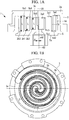
- Fig. 1 illustrates a fixed scroll (first scroll member) 3 and an orbiting scroll (second scroll member) 5 of a scroll compressor (scroll fluid machine) 1.
- the scroll compressor 1 is used as a compressor that compresses a gas refrigerant (fluid) for performing refrigerating cycle of an air conditioner or the like, for example.
- the fixed scroll 3 and the orbiting scroll 5 are a compression mechanism made of metal such as aluminum alloy and iron, and are housed in a housing (not illustrated).
- the fixed scroll 3 and the orbiting scroll 5 suck, from the outer circumferential side, fluid guided into the housing, and discharge the compressed fluid from a discharge port 3c at the center of the fixed scroll 3 to the outside.
- the fixed scroll 3 is fixed to the housing, and includes a substantially disk-shaped end plate (first end plate) 3a, and a spiral wall (first wall) 3b erected on a side surface of the end plate 3a, as illustrated in Fig. 1A .
- the orbiting scroll 5 includes a substantially disk-shaped end plate (second end plate) 5a, and a spiral wall (second wall) 5b erected on a side surface of the end plate 5a.
- the respective spiral shapes of the walls 3b, 5b are each defined by using, for example, an involute curve or an Archimedes curve.
- the center of the fixed scroll 3 and the center of the orbiting scroll 5 are separated by an orbiting radius p, are engaged such that the phases of the walls 3b, 5b are shifted by 180°, and are assembled so as to have slight clearances (tip clearances) in the height direction between tooth tips and tooth bottoms of the walls 3b, 5b of both the scrolls at normal temperature. Consequently, a plurality of pairs of compression chambers formed so as to be surrounded by the end plates 3a, 5a and the walls 3b, 5b are formed between the scrolls 3, 5 so as to be symmetrical with respect to the scroll centers.
- the orbiting scroll 5 revolves around the fixed scroll 3 by a rotation prevention mechanism such as an Oldham ring (not illustrated).
- a wall inclined section 5b1 having a height that continuously reduces from the outer circumferential side toward inner circumferential side is provided in the wall 5b of the orbiting scroll 5.
- An end plate inclined section 3a1 (see Fig. 1A ) that inclines in accordance with inclination of the wall inclined section 5b1 is provided in a tooth bottom surface of the fixed scroll 3 facing a tooth tip of this wall inclined section 5b1.
- the continuous inclined section is formed by these wall inclined section 5b1 and end plate inclined section 3a1.
- a wall inclined section 3b1 having a height that continuously inclines from the outer circumferential side toward inner circumferential side is provided in the wall 3b of the fixed scroll 3, and an end plate inclined section 5a1 facing a tooth tip of this wall inclined section 3b1 is provided in the end plate 5a of the orbiting scroll 5.
- the meaning of "continuously” in the inclined section mentioned in this embodiment is not limited to smoothly connected inclination, but includes inclination that is formed by stepwisely connecting small step sections inevitably generated in machining, and that is an inclined section continuously inclined as a whole. However, the above meaning does not include a large step section such as a so-called stepped scroll.
- the wall inclined sections 3b1, 5b1 and/or the end plate inclined sections 3a1, 5a1 are coated.
- the coating include manganese phosphate treatment, and nickel-phosphorus plating.
- wall flat sections 5b2, 5b3 each having a constant height are provided on the innermost circumferential side and the outermost circumferential side of the wall 5b of the orbiting scroll 5, respectively.
- These wall flat sections 5b2, 5b3 are each provided over a region of 180° around the center 02 (see Fig. 1A ) of the orbiting scroll 5.
- Wall inclined connecting sections 5b4, 5b5 serving as bent sections are provided at respective positions where the wall flat sections 5b2, 5b3 and the wall inclined section 5b1 are connected.
- end plate flat sections 5a2, 5a3 each having a constant height are provided on a tooth bottom of the end plate 5a of the orbiting scroll 5.
- These end plate flat sections 5a2, 5a3 are also each provided over a region of 180° around the center of the orbiting scroll 5.
- End plate inclined connecting sections 5a4, 5a5 serving as bent sections are provided at respective positions where the end plate flat sections 5a2, 5a3 and the end plate inclined section 5a1 are connected.
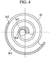
- end plate flat sections 3a2, 3a3, wall flat sections 3b2, 3b3, end plate inclined connecting sections 3a4, 3a5, and wall inclined connecting sections 3b4, 3b5 are provided in the fixed scroll 3, like the orbiting scroll 5.
- Fig. 5 illustrates the walls 3b, 5b represented so as to extend in the spiral direction.
- the wall flat sections 3b2, 5b2 on the innermost circumferential sides are each provided so as to extend over a distance D2
- the wall flat sections 3b3, 5b3 on the outermost circumferential sides are each provided so as to extend over a distance D3.
- the distance D2 and the distance D3 are equivalent to the lengths of the regions of 180° (180° or more and 360° or less, preferably 210° or less) around the centers O1, O2 of the scrolls 3, 5.
- the wall inclined sections 3b1, 5b1 are provided between the wall flat sections 3b2, 5b2 on the innermost circumferential sides and the wall flat sections 3b3, 5b3 on the outermost circumferential sides so as to extend over a distance D1.
- the inclination ⁇ in the inclined section is constant with respect to the circumferential direction in which each of the spiral walls 3b, 5b extends.
- the distance D1 is longer than the distance D2, and is longer than the distance D3.
- the specifications of the scrolls 3, 5 are as follows.
- a tip seal 7 is provided on the tooth tip of the wall 3b of the fixed scroll 3.
- the tip seal 7 is made of resin, and comes into contact with the tooth bottom of the end plate 5a of the facing orbiting scroll 5 to seal fluid.
- the tip seal 7 is housed in a tip seal groove 3d formed in the circumferential direction of the tooth tip of the wall 3b. Compressed fluid enters this tip seal groove 3d, and the tip seal 7 is pressed from a back surface, and pressed out to the tooth bottom side to be brought into contact with the facing tooth bottom.
- a tip seal is provided on the tooth tip of the wall 5b of the orbiting scroll 5.
- the height Hc of the tip seal 7 in the height direction of the wall 3b is constant in the circumferential direction.
- a tip clearance change amount ⁇ h [mm] is, for example, 0.05 or more and 1.0 or less, preferably 0.1 or more and 0.6 or less.
- the tip clearance T is small in Fig. 7A
- the tip clearance T is large in Fig. 7B . Even when this tip clearance T changes due to the orbiting movement, the tip seal 7 is pressed to the tooth bottom side of the end plate 5a from the back surface by compressed fluid, and therefore can seal following this pressing.
- Fig. 8 illustrates a cross-section of the vicinity of a tooth tip cut in the radial direction at a predetermined position of the wall inclined section 3b1 of the fixed scroll 3.
- a cross-section of the vicinity of a tooth tip cut in the radial direction in the wall inclined section 5b1 of the orbiting scroll 5 has a similar shape. Therefore, in the following description, only relation between the tooth tip of the wall inclined section 3b1 of the fixed scroll 3, and a tooth bottom of the end plate inclined section 5a1 of the orbiting scroll 5 facing the fixed scroll 3 will be described.
- the tooth tip of the wall 3b and the tooth bottom of the end plate 5a are located so as to face each other.
- the tip seal 7 stored in the tip seal groove 3d is disposed in the tooth tip of the wall 3b.
- the groove width Tw of the tip seal groove 3d is formed slightly larger than the width of the tip seal 7.
- Reference symbol Tr denotes the width of the wall 3b.
- Reference symbol Ta denotes a bank width equivalent to a dimension of the tooth tip from a circumferential wall part of the wall 3b to the tip seal groove 3d. That is, a region of the bank width Ta is a region where the tip seal groove 3d is not formed in the tooth tip.
- the tip seal 7 is pressed on the tooth bottom side (lower side in Fig. 8 ) by pressure of fluid entering on the back surface of the tip seal 7.
- the wall 3b is located in the vicinity of a first wall 5bR (right in Fig. 8 ), and forms a seal at this position so as to close a compression chamber.
- the wall 3b is separated from a second wall 5bL (left in Fig. 8 ), and the compression chamber is formed between the wall 3b and the second wall 5bL.
- Step sections 9a that protrude from a central tooth bottom are formed on tooth bottom corners 9 at bases of the wall 5b.
- the step sections 9a each have a step section width Sw, and are each located so as to face a tooth tip corner 8 of the wall 3b.
- the tip seal groove 3d is formed so as to be shifted on the center side in the thickness direction of the wall 3b with respect to positions facing the step sections 9a. That is, the bank width Ta of the tooth tip of the wall 3b is a dimension larger than the step section width Sw of the step section 9a of each tooth bottom corner 9. Consequently, the tip seal 7 is installed at such a position not to come into contact with the step sections 9a.
- the step sections 9a located at the tooth bottom corners 9 are inevitably formed by machining for the end plate inclined section 5a1. This is because machining for forming an inclined surface on the tooth bottom of the end plate 5a has a higher degree of difficulty than machining for a flat surface.
- the end plate inclined section 5a1 is machined by a machining step including the following three passes.
- machining in a first pass a circumferential wall surface of the first wall 5bR and an adjacent tooth bottom are machined by an end mill (first circumferential wall surface machining step).
- a machining pitch in this step is given as an instruction program of an NC (Numerical Control) machine tool, as a first machining pitch p1.
- the diameter of the end mill at this time is De, and is a slightly smaller dimension than a tooth bottom width Tg.
- machining in a second pass a circumferential wall surface of the second wall 5bL and an adjacent tooth bottom are machined by the end mill (second circumferential wall surface machining step).
- a machining pitch in this step is the first machining pitch p1 that is the same as the machining pitch in the first pass.
- the diameter De which is the same as the diameter in the first pass is used.
- tooth bottom machining step As a machining pitch in this step, a second machining pitch p2 finer than the first machining pitch p1 in each of the first pass and the second pass is used. Consequently, the inclination of the tooth bottom surface is formed as smoothly as possible.
- the diameter of an end mill is a dimension smaller than the tooth bottom width Tg, and for example, the diameter De which is the same as the diameter in each of the first pass and the second pass is used.
- the end plate inclined section 5a1 and the circumferential wall surfaces of the wall 5b adjacent thereto are machined through the machining step including three passes.
- the second machining pitch p2 used in the third pass for machining the tooth bottom is finer than the first machining pitch p1 in each of the first pass and the second pass, and therefore the step sections 9a remain on the tooth bottom corners 9 on both sides where the machining in the third pass is not performed.
- the step section width Sw of each step section 9a is (Tg - De)/2.
- the step section 9a can be generated by difference (machining error) between the edge height (vertical direction in Fig. 8 ) of the end mill in the machining in each of the first pass and the second pass, and the edge height of the end mill in the machining in the third pass.
- the machining for the wall inclined section 3b1 that is the tooth tip of the wall 3b is performed by use of the second machining pitch p2 which is the same as the machining pitch in the aforementioned third pass machining. Thereafter, machining for forming the tip seal groove 3d is performed.
- the aforementioned scroll compressor 1 is operated as follows.
- the orbiting scroll 5 revolves around the fixed scroll 3 by a driving source such as an electric motor (not illustrated). Consequently, fluid is sucked from the outer circumferential sides of the scrolls 3, 5, and is taken in the compression chambers surrounded by the walls 3b, 5b and the end plates 3a, 5a.
- the fluid in the compression chambers is sequentially compressed in accordance with movement from the outer circumferential side to the inner circumferential side, and the compressed fluid is finally discharged from the discharge port 3c formed in the fixed scroll 3.
- the fluid is compressed also in the height direction of the walls 3b, 5b in the inclined sections formed by the end plate inclined sections 3a1, 5a1 and the wall inclined sections 3b1, 5b1, and is three-dimensionally compressed.
- the step sections 9a are formed on the tooth bottom corners 9 at the base of the wall 5b.
- the tip seal 7 comes into contact with this step section 9a so as to spread over the step section 9a, a clearance is generated between the tip seal 7 and the tooth bottom and fluid leakage may occur, and abrasion of the tip seal 7 may be caused.
- the tip seal groove 3d is formed on the center side in the thickness direction of the wall 3b with respect to the positions facing the step sections 9a, so that the tip seal 7 does not come into contact with the step sections 9a. That is, the bank width Ta is made larger than the step section width Sw (Ta > Sw). Consequently, it is possible to reduce leakage and suppress the abrasion of the tip seal 7, and it is possible to suppress reduction of the performance of the scroll compressor 1.
- the step sections 9a are easily generated on the tooth bottom corners 9 due to the difficulty of the machining, and therefore it is particularly effective that the tip seal groove 3d is located so as not to face the step sections 9a, so that the tip seal 7 does not come into contact with the step sections 9a.
- a configuration for avoiding contact with the step sections 9a generated in a case where the tooth bottom is machined by the three passes is described.
- the present invention can be also applied to a step section 9a' generated in a case where a tooth bottom is machined by two passes, as illustrated in Fig. 9 .
- a circumferential wall surface of a first wall 5bR and an adjacent tooth bottom are machined by an end mill.
- machining in a second pass a circumferential wall surface of a second wall 5bL and an adjacent tooth bottom are machined by an end mill.
- the tooth bottom formed at this time is a final shape.
- a machining pitch a second machining pitch p2 smaller than a first machining pitch p1 in the first pass may be used, or the first machining pitch p1 may be used.
- a step section width Sw' is (Tg - De).
- a tip seal groove 3d is formed on the center side in the thickness direction of a wall 3b with respect to a position facing the step sections 9a' so as to avoid contact with the step sections 9a'. Consequently, it is possible to avoid contact of the step sections 9a' generated by the machining by the two passes with the tip seal 7 to suppress the performance deterioration of the scroll compressor 1.
- the end plate inclined sections 3a1, 5a1 and the wall inclined sections 3b1, 5b1 are provided in both the scrolls 3, 5 in this embodiment, but may be provided in either one.
- a wall inclined section 5b1 is provided in a first wall (for example, an orbiting scroll 5), and an end plate inclined section 3a1 is provided in a second end plate 3a
- a second wall and a first end plate 5a may be flat.
- a shape formed by combination with a conventional stepped shape that is, a shape, in which while an end plate inclined section 3a1 is provided in an end plate 3a of a fixed scroll 3, a step section is provided in an end plate 5a of an orbiting scroll 5, may be combined.
- end plate flat sections 3b2, 3b3, 5b2, 5b3, and the end plate flat sections 3a2, 3a3, 5a2, 5a3 are provided.
- the flat sections on the inner circumferential sides and/or the outer circumferential sides may be omitted, and the inclined sections may be provided so as to extend over the entire walls 3b, 5b.
- the scroll compressor 1 having the inclined sections is employed.
- the step sections 9a, 9a' can be each generated by the machining error of the tooth bottom corner. Therefore, the present invention can be also applied to the general scroll compressor with no step section or the stepped scroll compressor.
- the present invention is applied to a scroll compressor in this embodiment, but can be also applied to a scroll expander used as an expander.
Landscapes
- Engineering & Computer Science (AREA)
- Mechanical Engineering (AREA)
- General Engineering & Computer Science (AREA)
- Rotary Pumps (AREA)
- Applications Or Details Of Rotary Compressors (AREA)
Abstract
Description
- The present invention relates to a scroll fluid machine and a machining method for a scroll member.
- Generally, there is known a scroll fluid machine in which a fixed scroll member and an orbiting scroll member provided with respective spiral walls on respective end plates are engaged and revolved to compress or expand fluid.
- As such a scroll fluid machine, a so-called stepped scroll compressor disclosed in
PTL 1 is known. In this stepped scroll compressor, respective step sections are provided at positions along the spiral directions of tooth tip surfaces and tooth bottom surfaces of spiral walls of a fixed scroll and an orbiting scroll, and the height of the outer circumferential side of the wall is made higher than the height of the inner circumferential side of the wall with each step section as a boundary. The stepped scroll compressor performs compression not only in the circumferential direction of the walls, but also in the height direction (three-dimensional compression), and therefore it is possible to increase displacement and increase compressor capacity compared to a general scroll compressor with no step section (two-dimensional compression). - [PTL 1] Japanese Unexamined Patent Application, Publication No.
2015-55173 - However, the stepped scroll compressor has a problem that fluid leakage at the step sections is large. Further, there is a problem that stress is concentrated on root portions of the step sections, and strength is reduced.
- To cope with the above, the inventors are considering providing continuous inclined sections in place of the step sections provided on the walls and the end plates.
- However, there is a problem that machining for an inclined section has a higher degree of difficulty than machining for a flat surface. When machining accuracy of a tooth bottom corner at a base of a wall is reduced, there is a risk that a step section may be formed on the tooth bottom corner, and come into contact with a tip seal. When the tip seal spreads over and comes into contact with the step section, a clearance is generated between the tip seal and the tooth bottom, so that leakage of fluid occurs. Further, abrasion may excessively proceed due to sliding of the tip seal against the step section. This may cause performance deterioration of the scroll fluid machine.
- Not only in a scroll fluid machine having inclined sections, but also in a general scroll compressor with no step section or a stepped scroll compressor, such a problem may be caused by a machining error of the tooth bottom corner.
- The present invention has been made in view of such a circumstance, and an object of the present invention is to provide a scroll fluid machine and a machining method for a scroll member, in which contact between a step section formed on a tooth bottom corner and a tip seal is prevented.
- In order to solve the aforementioned problems, a scroll fluid machine and a machining method for a scroll member of the present invention employs the following solutions.
- A scroll fluid machine according to an aspect of the present invention is a scroll fluid machine including: a first scroll member provided with a spiral first wall on a first end plate; a second scroll member that is provided with a spiral second wall on a second end plate disposed so as to face the first end plate, and that relatively revolves by engagement between the second wall and the first wall; and a tip seal that is provided in a groove section formed in a tooth tip of each of the first wall and the second wall, and that comes into contact with a facing tooth bottom to seal fluid, wherein a step section is provided on a tooth bottom corner at a base of one of the walls facing a tooth tip corner of another wall, and the groove section is formed on a center side in a thickness direction of the wall with respect to a position facing the step section.
- When a tooth bottom is machined, a step section is sometimes formed on a tooth bottom corner at a base of a wall. When the tip seal spreads over and comes into contact with the step section, a clearance may be generated between the tip seal and the tooth bottom, leakage of fluid may occur, and abrasion of the tip seal may be caused.
- To cope with the above, the groove section is formed on the center side in the thickness direction of the wall with respect to the position facing the step section, so that the tip seal does not come into contact with the step section. Consequently, it is possible to reduce fluid leakage from the clearance between the tip seal and the step section, and suppress the abrasion of the tip seal, and it is possible to suppress reduction of the performance of the scroll fluid machine.
- The step section provided on the tooth bottom corner includes a step section inevitably formed by machining.
- The scroll fluid machine according to the aspect of the present invention includes an inclined section that continuously reduces an inter-facing-surface distance between the first end plate and the second end plate facing each other, from an outer circumferential side toward an inner circumferential side of each of the first wall and the second wall, wherein each of the inclined sections is provided over a range of 180° or more around a spiral center.
- The inclined section that continuously reduces the inter-facing-surface distance between the first end plate and the second end plate from the outer circumferential side toward the inner circumferential side of each wall is provided, and therefore fluid sucked from the outer circumferential side is not only compressed by reduction of compression chambers in accordance with the spiral shape of the wall, but also further compressed by reduction of the inter-facing-surface distance between the end plates, toward the inner circumferential side.
- The machining for the inclined section has a higher degree of difficulty than machining for a flat surface, and therefore machining accuracy of the tooth bottom corner at the base of the wall may be reduced. When the machining accuracy of the tooth bottom corner is reduced, a step section is generated on the tooth bottom corner.
- For example, when one of circumferential wall surfaces of the wall and an adjacent tooth bottom are machined, and thereafter another circumferential wall surface facing the one circumferential wall surface with a common tooth bottom therebetween, and an adjacent tooth bottom are machined, the machining is performed through the machining steps of at least two passes. In this case, it is difficult that the heights of the tooth bottoms exactly coincide in the two passes, and therefore deviation in height between the tooth bottoms is caused, and the step section is generated on the tooth bottom adjacent to each tooth bottom corner.
- In a case where one of circumferential wall surfaces of the wall and an adjacent tooth bottom are machined at a predetermined first machining pitch, another circumferential wall surface of the wall and an adjacent tooth bottom are machined at the same first machining pitch, and thereafter only a tooth bottom is machined at a second machining pitch finer than the first machining pitch, step sections corresponding to the first machining pitch rougher than the second machining pitch are generated on the tooth bottoms adjacent to the tooth bottom corners.
- Thus, in the scroll member having the inclined section, the step sections are easily generated on the tooth bottom corners, and therefore it is particularly effective that as described above, the groove section is located so as not to face the step sections, so that the tip seal does not come into contact with the step sections.
- A machining method for a scroll member according to an aspect of the present invention is a machining method for a scroll member, the scroll member including: an end plate; and a spiral wall provided on the end plate, the scroll member being provided with a groove section storing a tip seal on a tooth tip of the wall, the machining method for a scroll member including: a first circumferential wall surface machining step of machining one of circumferential wall surfaces of the wall and an adjacent tooth bottom; a second circumferential wall surface machining step of machining another circumferential wall surface of the wall, and an adjacent tooth bottom; and a groove section machining step of forming the groove section on a tooth tip of the end plate, wherein a step section is provided on a tooth bottom corner at a base of the wall, and the groove section is formed on a center side in a thickness direction of the wall with respect to a position facing the step section.
- The first circumferential surface machining step and the second circumferential surface machining step are performed, and thereafter the step section is formed on the tooth bottom corner due to machining accuracy or the like. The groove section is formed at such a position not to face this step section. Consequently, it is possible to avoid contact between the tip seal and the step section.
- The step section provided on the tooth bottom corner includes a step section inevitably formed by machining.
- Further, the scroll member includes a wall inclined section that has a height of the wall continuously reducing from an outer circumferential side toward an inner circumferential side, and/or an end plate inclined section that has a height of the end plate continuously increasing from the outer circumferential side toward the inner circumferential side, and the wall inclined section and the end plate inclined section are each provided over a range of 180° or more around a spiral center.
- A machining method for a scroll member according to an aspect of the present invention is a machining method for a scroll member, the scroll member including: an end plate; and a spiral wall provided on the end plate, the scroll member being provided with an inclined section having a height from a tooth bottom to a tooth tip of the wall, the height being continuously changed in a spiral direction, the inclined section being provided over a range of 180° or more around a spiral center, the machining method for a scroll member including: a first circumferential wall surface machining step of machining one of circumferential wall surfaces of the wall and an adjacent tooth bottom; a second circumferential wall surface machining step of machining another circumferential wall surface of the wall, and an adjacent tooth bottom; a tooth bottom machining step of machining only a tooth bottom between the one circumferential wall surface and the other circumferential wall surface; and a groove section machining step of forming a groove section on a tooth tip of the end plate, wherein a step section is provided on a tooth bottom corner at a base of the wall, and the groove section is formed on a center side in a thickness direction of the wall with respect to a position facing the step section.
- The machining for the inclined section has a higher degree of difficulty than machining for a flat surface. Therefore, the step of machining each of the circumferential wall surfaces, and the step of machining only the tooth bottom are divided, and the circumferential wall surfaces and the tooth bottom are machined by three passes. Consequently, it is possible to accurately machine the tooth bottom that becomes the inclined section.
- In the scroll member having the inclined section and having high degree of difficulty of machining, the step sections are easily generated on the tooth bottom corners, and therefore it is particularly effective that the groove section is located so as not to face the step sections as described above, so that the tip seal does not come into contact with the step sections.
- The machining pitch of the tooth bottom machining step is made finer than the machining pitch of each of the circumferential wall surface machining steps, and the inclined sections of the tooth bottoms are preferably accurately machined.
- The tooth tip of the inclined section is preferably machined as a machining pitch equivalent to the tooth bottom machining step.
- The step sections provided on the tooth bottom corners include step sections inevitably formed by machining.
- The groove section is formed on the center side in the thickness direction of the wall with respect to the position facing the step section, and therefore it is possible to prevent contact between the tip seal and the step section. Consequently, it is possible to reduce fluid leakage from a clearance between the tip seal and the step section, and suppress the abrasion of the tip seal, and it is possible to suppress reduction of the performance of the scroll fluid machine.
-
- [
Fig. 1A] Fig. 1A is a longitudinal sectional view illustrating a fixed scroll and an orbiting scroll of a scroll compressor according to one embodiment of the present invention. - [
Fig. 1B] Fig. 1B is a plan view of the fixed scroll ofFig. 1A viewed from a wall side. - [
Fig. 2] Fig. 2 is a perspective view illustrating the orbiting scroll ofFig. 1 . - [
Fig. 3] Fig. 3 is a plan view illustrating end plate flat sections provided in the fixed scroll. - [
Fig. 4] Fig. 4 is a plan view illustrating a wall flat section provided in the fixed scroll. - [
Fig. 5] Fig. 5 is a schematic diagram illustrating a wall represented so as to extend in the spiral direction. - [
Fig. 6] Fig. 6 is a partially enlarged view illustrating an enlarged region of reference symbol Z inFig. 1B . - [
Fig. 7A] Fig. 7A is a side view illustrating a tip seal clearance of a portion illustrated inFig. 6 , and illustrating a state in which the tip seal clearance is relatively small. - [
Fig. 7B] Fig. 7B is a side view illustrating the tip seal clearance of the portion illustrated inFig. 6 , and illustrating a state in which the tip seal clearance is relatively large. - [
Fig. 8] Fig. 8 is a longitudinal sectional view illustrating a cross-section of the vicinity of a tooth tip cut in the radial direction in an inclined section. - [
Fig. 9] Fig. 9 is a longitudinal sectional view illustrating a modification ofFig. 8 . - [
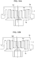
Fig. 10A] Fig. 10A is a longitudinal sectional view illustrating a modified example, and illustrating combination of scrolls having no step section. - [
Fig. 10B] Fig. 10B is a longitudinal sectional view illustrating a modified example, and illustrating combination of stepped scrolls. - Hereinafter, one embodiment according to the present invention will be described with reference to the drawings.
-
Fig. 1 illustrates a fixed scroll (first scroll member) 3 and an orbiting scroll (second scroll member) 5 of a scroll compressor (scroll fluid machine) 1. Thescroll compressor 1 is used as a compressor that compresses a gas refrigerant (fluid) for performing refrigerating cycle of an air conditioner or the like, for example. - The fixed
scroll 3 and theorbiting scroll 5 are a compression mechanism made of metal such as aluminum alloy and iron, and are housed in a housing (not illustrated). The fixedscroll 3 and theorbiting scroll 5 suck, from the outer circumferential side, fluid guided into the housing, and discharge the compressed fluid from adischarge port 3c at the center of the fixedscroll 3 to the outside. - The fixed
scroll 3 is fixed to the housing, and includes a substantially disk-shaped end plate (first end plate) 3a, and a spiral wall (first wall) 3b erected on a side surface of theend plate 3a, as illustrated inFig. 1A . Theorbiting scroll 5 includes a substantially disk-shaped end plate (second end plate) 5a, and a spiral wall (second wall) 5b erected on a side surface of theend plate 5a. The respective spiral shapes of thewalls - The center of the fixed
scroll 3 and the center of theorbiting scroll 5 are separated by an orbiting radius p, are engaged such that the phases of thewalls walls end plates walls scrolls orbiting scroll 5 revolves around the fixedscroll 3 by a rotation prevention mechanism such as an Oldham ring (not illustrated). - As illustrated in
Fig. 1A , inclined sections that continuously reduce an inter-facing-surface distance L between the facingend plates spiral walls - As illustrated in
Fig. 2 , a wall inclined section 5b1 having a height that continuously reduces from the outer circumferential side toward inner circumferential side is provided in thewall 5b of theorbiting scroll 5. An end plate inclined section 3a1 (seeFig. 1A ) that inclines in accordance with inclination of the wall inclined section 5b1 is provided in a tooth bottom surface of the fixedscroll 3 facing a tooth tip of this wall inclined section 5b1. The continuous inclined section is formed by these wall inclined section 5b1 and end plate inclined section 3a1. Similarly, a wall inclined section 3b1 having a height that continuously inclines from the outer circumferential side toward inner circumferential side is provided in thewall 3b of the fixedscroll 3, and an end plate inclined section 5a1 facing a tooth tip of this wall inclined section 3b1 is provided in theend plate 5a of theorbiting scroll 5. - The meaning of "continuously" in the inclined section mentioned in this embodiment is not limited to smoothly connected inclination, but includes inclination that is formed by stepwisely connecting small step sections inevitably generated in machining, and that is an inclined section continuously inclined as a whole. However, the above meaning does not include a large step section such as a so-called stepped scroll.
- The wall inclined sections 3b1, 5b1 and/or the end plate inclined sections 3a1, 5a1 are coated. Examples of the coating include manganese phosphate treatment, and nickel-phosphorus plating.
- As illustrated in
Fig. 2 , wall flat sections 5b2, 5b3 each having a constant height are provided on the innermost circumferential side and the outermost circumferential side of thewall 5b of theorbiting scroll 5, respectively. These wall flat sections 5b2, 5b3 are each provided over a region of 180° around the center 02 (seeFig. 1A ) of theorbiting scroll 5. Wall inclined connecting sections 5b4, 5b5 serving as bent sections are provided at respective positions where the wall flat sections 5b2, 5b3 and the wall inclined section 5b1 are connected. - Similarly, end plate flat sections 5a2, 5a3 each having a constant height are provided on a tooth bottom of the
end plate 5a of theorbiting scroll 5. These end plate flat sections 5a2, 5a3 are also each provided over a region of 180° around the center of theorbiting scroll 5. End plate inclined connecting sections 5a4, 5a5 serving as bent sections are provided at respective positions where the end plate flat sections 5a2, 5a3 and the end plate inclined section 5a1 are connected. - As illustrated by hatching in
Fig. 3 andFig. 4 , end plate flat sections 3a2, 3a3, wall flat sections 3b2, 3b3, end plate inclined connecting sections 3a4, 3a5, and wall inclined connecting sections 3b4, 3b5 are provided in the fixedscroll 3, like theorbiting scroll 5. -
Fig. 5 illustrates thewalls Fig. 5 , the wall flat sections 3b2, 5b2 on the innermost circumferential sides are each provided so as to extend over a distance D2, and the wall flat sections 3b3, 5b3 on the outermost circumferential sides are each provided so as to extend over a distance D3. The distance D2 and the distance D3 are equivalent to the lengths of the regions of 180° (180° or more and 360° or less, preferably 210° or less) around the centers O1, O2 of thescrolls 
- Thus, the inclination ϕ in the inclined section is constant with respect to the circumferential direction in which each of the
spiral walls - For example, in this embodiment, the specifications of the
scrolls - (1) Orbiting radius ρ [mm]: 2 or more and 15 or less, preferably 3 or more and 10 or less
- (2) The number of turns of each of the
walls - (3) Height difference h [mm]: 2 or more and 20 or less, preferably 5 or more and 15 or less
- (4) h/Lout (wall height on outermost circumferential side): 0.05 or more and 0.35 or less, preferably 0.1 or more and 0.25 or less
- (5) Angular range of inclined section (angular range equivalent to distance D1) [°]: 180 or more and 1080 or less, preferably 360 or more and 720 or less
- (6) Angle Φ[°] of inclined section: 0.2 or more and 4 or less, preferably 0.5 or more and 2.5 or less
- In
Fig. 6 , an enlarged view of a region indicated by reference symbol Z inFig. 1B is illustrated. As illustrated inFig. 6 , atip seal 7 is provided on the tooth tip of thewall 3b of the fixedscroll 3. Thetip seal 7 is made of resin, and comes into contact with the tooth bottom of theend plate 5a of the facing orbitingscroll 5 to seal fluid. Thetip seal 7 is housed in atip seal groove 3d formed in the circumferential direction of the tooth tip of thewall 3b. Compressed fluid enters thistip seal groove 3d, and thetip seal 7 is pressed from a back surface, and pressed out to the tooth bottom side to be brought into contact with the facing tooth bottom. Similarly, a tip seal is provided on the tooth tip of thewall 5b of theorbiting scroll 5. - As illustrated in
Fig. 7 , the height Hc of thetip seal 7 in the height direction of thewall 3b is constant in the circumferential direction. - When both the
scrolls Fig. 7A , and the tip clearance T is large inFig. 7B . Even when this tip clearance T changes due to the orbiting movement, thetip seal 7 is pressed to the tooth bottom side of theend plate 5a from the back surface by compressed fluid, and therefore can seal following this pressing. -
Fig. 8 illustrates a cross-section of the vicinity of a tooth tip cut in the radial direction at a predetermined position of the wall inclined section 3b1 of the fixedscroll 3. A cross-section of the vicinity of a tooth tip cut in the radial direction in the wall inclined section 5b1 of theorbiting scroll 5 has a similar shape. Therefore, in the following description, only relation between the tooth tip of the wall inclined section 3b1 of the fixedscroll 3, and a tooth bottom of the end plate inclined section 5a1 of theorbiting scroll 5 facing the fixedscroll 3 will be described. - As illustrated in
Fig. 8 , the tooth tip of thewall 3b and the tooth bottom of theend plate 5a are located so as to face each other. Thetip seal 7 stored in thetip seal groove 3d is disposed in the tooth tip of thewall 3b. The groove width Tw of thetip seal groove 3d is formed slightly larger than the width of thetip seal 7. Reference symbol Tr denotes the width of thewall 3b. Reference symbol Ta denotes a bank width equivalent to a dimension of the tooth tip from a circumferential wall part of thewall 3b to thetip seal groove 3d. That is, a region of the bank width Ta is a region where thetip seal groove 3d is not formed in the tooth tip. - The
tip seal 7 is pressed on the tooth bottom side (lower side inFig. 8 ) by pressure of fluid entering on the back surface of thetip seal 7. Thewall 3b is located in the vicinity of a first wall 5bR (right inFig. 8 ), and forms a seal at this position so as to close a compression chamber. Thewall 3b is separated from a second wall 5bL (left inFig. 8 ), and the compression chamber is formed between thewall 3b and the second wall 5bL. -
Step sections 9a that protrude from a central tooth bottom are formed on tooth bottom corners 9 at bases of thewall 5b. Thestep sections 9a each have a step section width Sw, and are each located so as to face atooth tip corner 8 of thewall 3b. - The
tip seal groove 3d is formed so as to be shifted on the center side in the thickness direction of thewall 3b with respect to positions facing thestep sections 9a. That is, the bank width Ta of the tooth tip of thewall 3b is a dimension larger than the step section width Sw of thestep section 9a of each tooth bottom corner 9. Consequently, thetip seal 7 is installed at such a position not to come into contact with thestep sections 9a. - The
step sections 9a located at the tooth bottom corners 9 are inevitably formed by machining for the end plate inclined section 5a1. This is because machining for forming an inclined surface on the tooth bottom of theend plate 5a has a higher degree of difficulty than machining for a flat surface. The end plate inclined section 5a1 is machined by a machining step including the following three passes. - First, as machining in a first pass, a circumferential wall surface of the first wall 5bR and an adjacent tooth bottom are machined by an end mill (first circumferential wall surface machining step). A machining pitch in this step is given as an instruction program of an NC (Numerical Control) machine tool, as a first machining pitch p1. The diameter of the end mill at this time is De, and is a slightly smaller dimension than a tooth bottom width Tg.
- Next, as machining in a second pass, a circumferential wall surface of the second wall 5bL and an adjacent tooth bottom are machined by the end mill (second circumferential wall surface machining step). A machining pitch in this step is the first machining pitch p1 that is the same as the machining pitch in the first pass. As the diameter of the end mill, the diameter De which is the same as the diameter in the first pass is used.
- Finally, as machining in a third pass, only the central tooth bottom between the circumferential wall surface of the first wall 5bR and the circumferential wall surface of the second wall 5bL is machined (tooth bottom machining step). As a machining pitch in this step, a second machining pitch p2 finer than the first machining pitch p1 in each of the first pass and the second pass is used. Consequently, the inclination of the tooth bottom surface is formed as smoothly as possible. The diameter of an end mill is a dimension smaller than the tooth bottom width Tg, and for example, the diameter De which is the same as the diameter in each of the first pass and the second pass is used.
- As described above, the end plate inclined section 5a1 and the circumferential wall surfaces of the
wall 5b adjacent thereto are machined through the machining step including three passes. At this time, the second machining pitch p2 used in the third pass for machining the tooth bottom is finer than the first machining pitch p1 in each of the first pass and the second pass, and therefore thestep sections 9a remain on the tooth bottom corners 9 on both sides where the machining in the third pass is not performed. - Assuming that the machining in the third pass is performed along the center of the tooth bottom width, the step section width Sw of each
step section 9a is (Tg - De)/2. - The
step section 9a can be generated by difference (machining error) between the edge height (vertical direction inFig. 8 ) of the end mill in the machining in each of the first pass and the second pass, and the edge height of the end mill in the machining in the third pass. - The machining for the wall inclined section 3b1 that is the tooth tip of the
wall 3b is performed by use of the second machining pitch p2 which is the same as the machining pitch in the aforementioned third pass machining. Thereafter, machining for forming thetip seal groove 3d is performed. - The
aforementioned scroll compressor 1 is operated as follows. - The
orbiting scroll 5 revolves around the fixedscroll 3 by a driving source such as an electric motor (not illustrated). Consequently, fluid is sucked from the outer circumferential sides of thescrolls walls end plates discharge port 3c formed in the fixedscroll 3. When the fluid is compressed, the fluid is compressed also in the height direction of thewalls - According to this embodiment, the following working effects are exhibited.
- When the tooth bottom is machined, the
step sections 9a are formed on the tooth bottom corners 9 at the base of thewall 5b. When thetip seal 7 comes into contact with thisstep section 9a so as to spread over thestep section 9a, a clearance is generated between thetip seal 7 and the tooth bottom and fluid leakage may occur, and abrasion of thetip seal 7 may be caused. - In this embodiment, the
tip seal groove 3d is formed on the center side in the thickness direction of thewall 3b with respect to the positions facing thestep sections 9a, so that thetip seal 7 does not come into contact with thestep sections 9a. That is, the bank width Ta is made larger than the step section width Sw (Ta > Sw). Consequently, it is possible to reduce leakage and suppress the abrasion of thetip seal 7, and it is possible to suppress reduction of the performance of thescroll compressor 1. - Like this embodiment, in the
scrolls step sections 9a are easily generated on the tooth bottom corners 9 due to the difficulty of the machining, and therefore it is particularly effective that thetip seal groove 3d is located so as not to face thestep sections 9a, so that thetip seal 7 does not come into contact with thestep sections 9a. - The step of machining the circumferential wall surface of each of the walls 5bR, 5bL, and the step of machining only the tooth bottom are divided, and the circumferential wall surfaces and the tooth bottom are machined by three passes. Consequently, it is possible to accurately machine the tooth bottom that becomes the inclined section.
- In this embodiment, a configuration for avoiding contact with the
step sections 9a generated in a case where the tooth bottom is machined by the three passes is described. However, the present invention can be also applied to astep section 9a' generated in a case where a tooth bottom is machined by two passes, as illustrated inFig. 9 . - The tooth bottom of an
end plate 5a illustrated inFig. 9 is machined by two passes as described below. - First, as machining in a first pass, a circumferential wall surface of a first wall 5bR and an adjacent tooth bottom are machined by an end mill.
- Next, as machining in a second pass, a circumferential wall surface of a second wall 5bL and an adjacent tooth bottom are machined by an end mill. The tooth bottom formed at this time is a final shape. In the second pass, as a machining pitch, a second machining pitch p2 smaller than a first machining pitch p1 in the first pass may be used, or the first machining pitch p1 may be used.
- When machining by such two passes is performed, the
step section 9a' is inevitably generated by the difference in machining pitch as described above, or the difference between the edge heights of the end mills in the first pass machining and the second pass machining (machining error). In this case, a step section width Sw' is (Tg - De). - A
tip seal groove 3d is formed on the center side in the thickness direction of awall 3b with respect to a position facing thestep sections 9a' so as to avoid contact with thestep sections 9a'. Consequently, it is possible to avoid contact of thestep sections 9a' generated by the machining by the two passes with thetip seal 7 to suppress the performance deterioration of thescroll compressor 1. - The end plate inclined sections 3a1, 5a1 and the wall inclined sections 3b1, 5b1 are provided in both the
scrolls - Specifically, as illustrated in
Fig. 10A , in a case where a wall inclined section 5b1 is provided in a first wall (for example, an orbiting scroll 5), and an end plate inclined section 3a1 is provided in asecond end plate 3a, a second wall and afirst end plate 5a may be flat. - As illustrated in
Fig. 10B , a shape formed by combination with a conventional stepped shape, that is, a shape, in which while an end plate inclined section 3a1 is provided in anend plate 3a of afixed scroll 3, a step section is provided in anend plate 5a of anorbiting scroll 5, may be combined. - In this embodiment, the end plate flat sections 3b2, 3b3, 5b2, 5b3, and the end plate flat sections 3a2, 3a3, 5a2, 5a3 are provided. However, the flat sections on the inner circumferential sides and/or the outer circumferential sides may be omitted, and the inclined sections may be provided so as to extend over the
entire walls - In this embodiment, the
scroll compressor 1 having the inclined sections is employed. However, even in a general scroll compressor with no step section or a stepped scroll compressor, thestep sections - The present invention is applied to a scroll compressor in this embodiment, but can be also applied to a scroll expander used as an expander.
-
- 1 scroll compressor (scroll fluid machine)
- 3 fixed scroll (first scroll member)
- 3a end plate (first end plate)
- 3a1 end plate inclined section
- 3a2 end plate flat section (inner circumferential side)
- 3a3 end plate flat section (outer circumferential side)
- 3a4 end plate inclined connecting section (inner circumferential side)
- 3a5 end plate inclined connecting section (outer circumferential side)
- 3b wall (first wall)
- 3b1 wall inclined section
- 3b2 wall flat section (inner circumferential side)
- 3b3 wall flat section (outer circumferential side)
- 3b4 wall inclined connecting section (inner circumferential side)
- 3b5 wall inclined connecting section (outer circumferential side)
- 3c discharge port
- 3d tip seal groove
- 5 orbiting scroll (second scroll member)
- 5a end plate (second end plate)
- 5a1 end plate inclined section
- 5a2 end plate flat section (inner circumferential side)
- 5a3 end plate flat section (outer circumferential side)
- 5a4 end plate inclined connecting section (inner circumferential side)
- 5a5 end plate inclined connecting section (outer circumferential side)
- 5b wall (second wall)
- 5b1 wall inclined section
- 5b2 wall flat section (inner circumferential side)
- 5b3 wall flat section (outer circumferential side)
- 5b4 wall inclined connecting section (inner circumferential side)
- 5b5 wall inclined connecting section (outer circumferential side)
- 7 tip seal
- 8 tooth tip corner
- 9 tooth bottom corner
- 9a step section
- De end mill diameter
- L inter-facing-surface distance
- Sw step section width
- T tip clearance
- Ta bank width
- Tr wall width
- Tw groove width
- Tg tooth bottom width
- Φ inclination
Claims (5)
- A scroll fluid machine comprising:a first scroll member provided with a spiral first wall on a first end plate;a second scroll member that is provided with a spiral second wall on a second end plate disposed so as to face the first end plate, and that relatively revolves by engagement between the second wall and the first wall; anda tip seal that is provided in a groove section formed in a tooth tip of each of the first wall and the second wall, and that comes into contact with a facing tooth bottom to seal fluid, whereina step section is provided on a tooth bottom corner at a base of one of the walls facing a tooth tip corner of another wall, andthe groove section is formed on a center side in a thickness direction of the wall with respect to a position facing the step section.
- The scroll fluid machine according to claim 1, comprising
an inclined section that continuously reduces an inter-facing-surface distance between the first end plate and the second end plate facing each other, from an outer circumferential side toward an inner circumferential side of each of the first wall and the second wall, wherein
each of the inclined sections is provided over a range of 180° or more around a spiral center. - A machining method for a scroll member, the scroll member including:an end plate; anda spiral wall provided on the end plate, the scroll member being provided with a groove section storing a tip seal on a tooth tip of the wall, the machining method for a scroll member comprising:a first circumferential wall surface machining step of machining one of circumferential wall surfaces of the wall and an adjacent tooth bottom;a second circumferential wall surface machining step of machining another circumferential wall surface of the wall, and an adjacent tooth bottom; anda groove section machining step of forming the groove section on a tooth tip of the end plate, whereina step section is provided on a tooth bottom corner at a base of the wall, andthe groove section is formed on a center side in a thickness direction of the wall with respect to a position facing the step section.
- The machining method for a scroll member according to claim 3, wherein
the scroll member includes a wall inclined section that has a height of the wall continuously reducing from an outer circumferential side toward an inner circumferential side, and/or an end plate inclined section that has a height of the end plate continuously increasing from the outer circumferential side toward the inner circumferential side, and
the wall inclined section and the end plate inclined section are each provided over a range of 180° or more around a spiral center. - A machining method for a scroll member, the scroll member including:an end plate; anda spiral wall provided on the end plate, the scroll member being provided with an inclined section having a height from a tooth bottom to a tooth tip of the wall, the height being continuously changed in a spiral direction, the machining method for a scroll member comprising:a first circumferential wall surface machining step of machining one of circumferential wall surfaces of the wall and an adjacent tooth bottom;a second circumferential wall surface machining step of machining another circumferential wall surface of the wall, and an adjacent tooth bottom;a tooth bottom machining step of machining only a tooth bottom between the one circumferential wall surface and the other circumferential wall surface; anda groove section machining step of forming a groove section on a tooth tip of the end plate, whereina step section is provided on a tooth bottom corner at a base of the wall, andthe groove section is formed on a center side in a thickness direction of the wall with respect to a position facing the step section.
Applications Claiming Priority (2)
| Application Number | Priority Date | Filing Date | Title |
|---|---|---|---|
| JP2018028962A JP6679634B2 (en) | 2018-02-21 | 2018-02-21 | Scroll member processing method |
| PCT/JP2019/000072 WO2019163308A1 (en) | 2018-02-21 | 2019-01-07 | Scroll fluid machine and machining method of scroll member |
Publications (4)
| Publication Number | Publication Date |
|---|---|
| EP3754197A1 true EP3754197A1 (en) | 2020-12-23 |
| EP3754197A4 EP3754197A4 (en) | 2021-07-28 |
| EP3754197B1 EP3754197B1 (en) | 2024-12-25 |
| EP3754197C0 EP3754197C0 (en) | 2024-12-25 |
Family
ID=67687623
Family Applications (1)
| Application Number | Title | Priority Date | Filing Date |
|---|---|---|---|
| EP19757682.0A Active EP3754197B1 (en) | 2018-02-21 | 2019-01-07 | Scroll fluid machine and machining method of scroll member |
Country Status (6)
| Country | Link |
|---|---|
| EP (1) | EP3754197B1 (en) |
| JP (1) | JP6679634B2 (en) |
| KR (1) | KR102380608B1 (en) |
| CN (1) | CN111712643B (en) |
| AU (1) | AU2019225259B2 (en) |
| WO (1) | WO2019163308A1 (en) |
Family Cites Families (12)
| Publication number | Priority date | Publication date | Assignee | Title |
|---|---|---|---|---|
| JPS5968583A (en) * | 1982-10-09 | 1984-04-18 | Sanden Corp | Scroll type fluid device |
| JP2910457B2 (en) * | 1992-09-11 | 1999-06-23 | 株式会社日立製作所 | Scroll fluid machine |
| JPH09158854A (en) * | 1995-12-07 | 1997-06-17 | Hitachi Ltd | Scroll compressor |
| JPH10141255A (en) * | 1996-11-01 | 1998-05-26 | Nisshin Seisakusho:Kk | Scroll compressor |
| JP4301713B2 (en) * | 2000-08-28 | 2009-07-22 | 三菱重工業株式会社 | Scroll compressor |
| JP4374206B2 (en) * | 2003-04-18 | 2009-12-02 | 日立アプライアンス株式会社 | Asymmetric wrap type scroll compressor and its processing method. |
| JP5851851B2 (en) * | 2012-01-13 | 2016-02-03 | 三菱重工業株式会社 | Scroll compressor |
| JP6180860B2 (en) | 2013-09-11 | 2017-08-16 | 三菱重工業株式会社 | Scroll compressor |
| CN204003446U (en) * | 2014-06-04 | 2014-12-10 | 恒升精密科技股份有限公司 | compressor scroll |
| JP6529787B2 (en) * | 2015-03-05 | 2019-06-12 | 三菱重工サーマルシステムズ株式会社 | Scroll fluid machine |
| JP6758969B2 (en) * | 2016-07-15 | 2020-09-23 | 三菱重工サーマルシステムズ株式会社 | Stepped scroll compressor and its design method |
| JP6336534B2 (en) * | 2016-08-26 | 2018-06-06 | 三菱重工サーマルシステムズ株式会社 | Scroll fluid machine and scroll member machining method |
-
2018
- 2018-02-21 JP JP2018028962A patent/JP6679634B2/en active Active
-
2019
- 2019-01-07 KR KR1020207023408A patent/KR102380608B1/en active Active
- 2019-01-07 CN CN201980013412.XA patent/CN111712643B/en active Active
- 2019-01-07 WO PCT/JP2019/000072 patent/WO2019163308A1/en not_active Ceased
- 2019-01-07 AU AU2019225259A patent/AU2019225259B2/en active Active
- 2019-01-07 EP EP19757682.0A patent/EP3754197B1/en active Active
Also Published As
| Publication number | Publication date |
|---|---|
| CN111712643A (en) | 2020-09-25 |
| KR20200108055A (en) | 2020-09-16 |
| JP6679634B2 (en) | 2020-04-15 |
| JP2019143553A (en) | 2019-08-29 |
| WO2019163308A1 (en) | 2019-08-29 |
| EP3754197B1 (en) | 2024-12-25 |
| EP3754197C0 (en) | 2024-12-25 |
| KR102380608B1 (en) | 2022-03-30 |
| EP3754197A4 (en) | 2021-07-28 |
| AU2019225259B2 (en) | 2021-04-29 |
| CN111712643B (en) | 2022-04-26 |
| AU2019225259A1 (en) | 2020-10-08 |
Similar Documents
| Publication | Publication Date | Title |
|---|---|---|
| EP3460245B1 (en) | Scroll fluid machine and tip seal | |
| US5425626A (en) | Scroll type fluid machine with an involute spiral based on a circle having a varying radius | |
| EP3428451B1 (en) | Scroll fluid machine, and method for processing scroll member | |
| AU2019225271B2 (en) | Scroll fluid machine | |
| EP3754197B1 (en) | Scroll fluid machine and machining method of scroll member | |
| EP3604812B1 (en) | Scroll fluid machine | |
| EP3722608B1 (en) | Scroll fluid machine and scroll member used therein | |
| EP3441615B1 (en) | Scroll fluid machine | |
| EP3444475B1 (en) | Scroll fluid machine | |
| JP6336535B2 (en) | Scroll fluid machine and scroll member machining method | |
| EP3739213B1 (en) | Scroll fluid machine | |
| EP3741995B1 (en) | Scroll fluid machine | |
| JP2019035399A (en) | Scroll fluid machine |
Legal Events
| Date | Code | Title | Description |
|---|---|---|---|
| STAA | Information on the status of an ep patent application or granted ep patent |
Free format text: STATUS: THE INTERNATIONAL PUBLICATION HAS BEEN MADE |
|
| PUAI | Public reference made under article 153(3) epc to a published international application that has entered the european phase |
Free format text: ORIGINAL CODE: 0009012 |
|
| STAA | Information on the status of an ep patent application or granted ep patent |
Free format text: STATUS: REQUEST FOR EXAMINATION WAS MADE |
|
| 17P | Request for examination filed |
Effective date: 20200917 |
|
| AK | Designated contracting states |
Kind code of ref document: A1 Designated state(s): AL AT BE BG CH CY CZ DE DK EE ES FI FR GB GR HR HU IE IS IT LI LT LU LV MC MK MT NL NO PL PT RO RS SE SI SK SM TR |
|
| AX | Request for extension of the european patent |
Extension state: BA ME |
|
| DAV | Request for validation of the european patent (deleted) | ||
| DAX | Request for extension of the european patent (deleted) | ||
| A4 | Supplementary search report drawn up and despatched |
Effective date: 20210629 |
|
| RIC1 | Information provided on ipc code assigned before grant |
Ipc: F04C 18/02 20060101AFI20210623BHEP Ipc: F04C 29/00 20060101ALI20210623BHEP |
|
| STAA | Information on the status of an ep patent application or granted ep patent |
Free format text: STATUS: EXAMINATION IS IN PROGRESS |
|
| 17Q | First examination report despatched |
Effective date: 20230207 |
|
| GRAP | Despatch of communication of intention to grant a patent |
Free format text: ORIGINAL CODE: EPIDOSNIGR1 |
|
| STAA | Information on the status of an ep patent application or granted ep patent |
Free format text: STATUS: GRANT OF PATENT IS INTENDED |
|
| INTG | Intention to grant announced |
Effective date: 20240808 |
|
| GRAS | Grant fee paid |
Free format text: ORIGINAL CODE: EPIDOSNIGR3 |
|
| GRAA | (expected) grant |
Free format text: ORIGINAL CODE: 0009210 |
|
| STAA | Information on the status of an ep patent application or granted ep patent |
Free format text: STATUS: THE PATENT HAS BEEN GRANTED |
|
| AK | Designated contracting states |
Kind code of ref document: B1 Designated state(s): AL AT BE BG CH CY CZ DE DK EE ES FI FR GB GR HR HU IE IS IT LI LT LU LV MC MK MT NL NO PL PT RO RS SE SI SK SM TR |
|
| REG | Reference to a national code |
Ref country code: GB Ref legal event code: FG4D |
|
| REG | Reference to a national code |
Ref country code: CH Ref legal event code: EP |
|
| REG | Reference to a national code |
Ref country code: DE Ref legal event code: R096 Ref document number: 602019063965 Country of ref document: DE |
|
| REG | Reference to a national code |
Ref country code: IE Ref legal event code: FG4D |
|
| U01 | Request for unitary effect filed |
Effective date: 20250109 |
|
| RAP4 | Party data changed (patent owner data changed or rights of a patent transferred) |
Owner name: MITSUBISHI HEAVY INDUSTRIES THERMAL SYSTEMS, LTD. |
|
| U07 | Unitary effect registered |
Designated state(s): AT BE BG DE DK EE FI FR IT LT LU LV MT NL PT RO SE SI Effective date: 20250116 |
|
| U20 | Renewal fee for the european patent with unitary effect paid |
Year of fee payment: 7 Effective date: 20250114 |
|
| PG25 | Lapsed in a contracting state [announced via postgrant information from national office to epo] |
Ref country code: HR Free format text: LAPSE BECAUSE OF FAILURE TO SUBMIT A TRANSLATION OF THE DESCRIPTION OR TO PAY THE FEE WITHIN THE PRESCRIBED TIME-LIMIT Effective date: 20241225 |
|
| PG25 | Lapsed in a contracting state [announced via postgrant information from national office to epo] |
Ref country code: NO Free format text: LAPSE BECAUSE OF FAILURE TO SUBMIT A TRANSLATION OF THE DESCRIPTION OR TO PAY THE FEE WITHIN THE PRESCRIBED TIME-LIMIT Effective date: 20250325 |
|
| PG25 | Lapsed in a contracting state [announced via postgrant information from national office to epo] |
Ref country code: GR Free format text: LAPSE BECAUSE OF FAILURE TO SUBMIT A TRANSLATION OF THE DESCRIPTION OR TO PAY THE FEE WITHIN THE PRESCRIBED TIME-LIMIT Effective date: 20250326 |
|
| PG25 | Lapsed in a contracting state [announced via postgrant information from national office to epo] |
Ref country code: RS Free format text: LAPSE BECAUSE OF FAILURE TO SUBMIT A TRANSLATION OF THE DESCRIPTION OR TO PAY THE FEE WITHIN THE PRESCRIBED TIME-LIMIT Effective date: 20250325 |
|
| PG25 | Lapsed in a contracting state [announced via postgrant information from national office to epo] |
Ref country code: SM Free format text: LAPSE BECAUSE OF FAILURE TO SUBMIT A TRANSLATION OF THE DESCRIPTION OR TO PAY THE FEE WITHIN THE PRESCRIBED TIME-LIMIT Effective date: 20241225 |
|
| PG25 | Lapsed in a contracting state [announced via postgrant information from national office to epo] |
Ref country code: PL Free format text: LAPSE BECAUSE OF FAILURE TO SUBMIT A TRANSLATION OF THE DESCRIPTION OR TO PAY THE FEE WITHIN THE PRESCRIBED TIME-LIMIT Effective date: 20241225 |
|
| PG25 | Lapsed in a contracting state [announced via postgrant information from national office to epo] |
Ref country code: ES Free format text: LAPSE BECAUSE OF FAILURE TO SUBMIT A TRANSLATION OF THE DESCRIPTION OR TO PAY THE FEE WITHIN THE PRESCRIBED TIME-LIMIT Effective date: 20241225 |
|
| PG25 | Lapsed in a contracting state [announced via postgrant information from national office to epo] |
Ref country code: IS Free format text: LAPSE BECAUSE OF FAILURE TO SUBMIT A TRANSLATION OF THE DESCRIPTION OR TO PAY THE FEE WITHIN THE PRESCRIBED TIME-LIMIT Effective date: 20250425 |
|
| PG25 | Lapsed in a contracting state [announced via postgrant information from national office to epo] |
Ref country code: SK Free format text: LAPSE BECAUSE OF FAILURE TO SUBMIT A TRANSLATION OF THE DESCRIPTION OR TO PAY THE FEE WITHIN THE PRESCRIBED TIME-LIMIT Effective date: 20241225 |
|
| PG25 | Lapsed in a contracting state [announced via postgrant information from national office to epo] |
Ref country code: CZ Free format text: LAPSE BECAUSE OF FAILURE TO SUBMIT A TRANSLATION OF THE DESCRIPTION OR TO PAY THE FEE WITHIN THE PRESCRIBED TIME-LIMIT Effective date: 20241225 |
|
| REG | Reference to a national code |
Ref country code: CH Ref legal event code: PL |
|
| PG25 | Lapsed in a contracting state [announced via postgrant information from national office to epo] |
Ref country code: MC Free format text: LAPSE BECAUSE OF FAILURE TO SUBMIT A TRANSLATION OF THE DESCRIPTION OR TO PAY THE FEE WITHIN THE PRESCRIBED TIME-LIMIT Effective date: 20241225 |
|
| PG25 | Lapsed in a contracting state [announced via postgrant information from national office to epo] |
Ref country code: CH Free format text: LAPSE BECAUSE OF NON-PAYMENT OF DUE FEES Effective date: 20250131 |
|
| PLBE | No opposition filed within time limit |
Free format text: ORIGINAL CODE: 0009261 |
|
| STAA | Information on the status of an ep patent application or granted ep patent |
Free format text: STATUS: NO OPPOSITION FILED WITHIN TIME LIMIT |
|
| 26N | No opposition filed |
Effective date: 20250926 |
|
| PGFP | Annual fee paid to national office [announced via postgrant information from national office to epo] |
Ref country code: GB Payment date: 20251127 Year of fee payment: 8 |
|
| U20 | Renewal fee for the european patent with unitary effect paid |
Year of fee payment: 8 Effective date: 20251205 |
|
| PG25 | Lapsed in a contracting state [announced via postgrant information from national office to epo] |
Ref country code: IE Free format text: LAPSE BECAUSE OF NON-PAYMENT OF DUE FEES Effective date: 20250107 |