EP3754193A1 - Compressor - Google Patents
Compressor Download PDFInfo
- Publication number
- EP3754193A1 EP3754193A1 EP19778367.3A EP19778367A EP3754193A1 EP 3754193 A1 EP3754193 A1 EP 3754193A1 EP 19778367 A EP19778367 A EP 19778367A EP 3754193 A1 EP3754193 A1 EP 3754193A1
- Authority
- EP
- European Patent Office
- Prior art keywords
- terminal
- section
- guard
- hole
- side wall
- Prior art date
- Legal status (The legal status is an assumption and is not a legal conclusion. Google has not performed a legal analysis and makes no representation as to the accuracy of the status listed.)
- Granted
Links
Images

Classifications
-
- F—MECHANICAL ENGINEERING; LIGHTING; HEATING; WEAPONS; BLASTING
- F04—POSITIVE - DISPLACEMENT MACHINES FOR LIQUIDS; PUMPS FOR LIQUIDS OR ELASTIC FLUIDS
- F04B—POSITIVE-DISPLACEMENT MACHINES FOR LIQUIDS; PUMPS
- F04B35/00—Piston pumps specially adapted for elastic fluids and characterised by the driving means to their working members, or by combination with, or adaptation to, specific driving engines or motors, not otherwise provided for
- F04B35/04—Piston pumps specially adapted for elastic fluids and characterised by the driving means to their working members, or by combination with, or adaptation to, specific driving engines or motors, not otherwise provided for the means being electric
-
- H—ELECTRICITY
- H02—GENERATION; CONVERSION OR DISTRIBUTION OF ELECTRIC POWER
- H02K—DYNAMO-ELECTRIC MACHINES
- H02K5/00—Casings; Enclosures; Supports
- H02K5/04—Casings or enclosures characterised by the shape, form or construction thereof
- H02K5/22—Auxiliary parts of casings not covered by groups H02K5/06-H02K5/20, e.g. shaped to form connection boxes or terminal boxes
- H02K5/225—Terminal boxes or connection arrangements
-
- F—MECHANICAL ENGINEERING; LIGHTING; HEATING; WEAPONS; BLASTING
- F04—POSITIVE - DISPLACEMENT MACHINES FOR LIQUIDS; PUMPS FOR LIQUIDS OR ELASTIC FLUIDS
- F04B—POSITIVE-DISPLACEMENT MACHINES FOR LIQUIDS; PUMPS
- F04B39/00—Component parts, details, or accessories, of pumps or pumping systems specially adapted for elastic fluids, not otherwise provided for in, or of interest apart from, groups F04B25/00 - F04B37/00
-
- F—MECHANICAL ENGINEERING; LIGHTING; HEATING; WEAPONS; BLASTING
- F04—POSITIVE - DISPLACEMENT MACHINES FOR LIQUIDS; PUMPS FOR LIQUIDS OR ELASTIC FLUIDS
- F04B—POSITIVE-DISPLACEMENT MACHINES FOR LIQUIDS; PUMPS
- F04B39/00—Component parts, details, or accessories, of pumps or pumping systems specially adapted for elastic fluids, not otherwise provided for in, or of interest apart from, groups F04B25/00 - F04B37/00
- F04B39/12—Casings; Cylinders; Cylinder heads; Fluid connections
-
- F—MECHANICAL ENGINEERING; LIGHTING; HEATING; WEAPONS; BLASTING
- F04—POSITIVE - DISPLACEMENT MACHINES FOR LIQUIDS; PUMPS FOR LIQUIDS OR ELASTIC FLUIDS
- F04B—POSITIVE-DISPLACEMENT MACHINES FOR LIQUIDS; PUMPS
- F04B39/00—Component parts, details, or accessories, of pumps or pumping systems specially adapted for elastic fluids, not otherwise provided for in, or of interest apart from, groups F04B25/00 - F04B37/00
- F04B39/12—Casings; Cylinders; Cylinder heads; Fluid connections
- F04B39/121—Casings
-
- F—MECHANICAL ENGINEERING; LIGHTING; HEATING; WEAPONS; BLASTING
- F04—POSITIVE - DISPLACEMENT MACHINES FOR LIQUIDS; PUMPS FOR LIQUIDS OR ELASTIC FLUIDS
- F04D—NON-POSITIVE-DISPLACEMENT PUMPS
- F04D29/00—Details, component parts, or accessories
- F04D29/40—Casings; Connections of working fluid
-
- H—ELECTRICITY
- H01—ELECTRIC ELEMENTS
- H01R—ELECTRICALLY-CONDUCTIVE CONNECTIONS; STRUCTURAL ASSOCIATIONS OF A PLURALITY OF MUTUALLY-INSULATED ELECTRICAL CONNECTING ELEMENTS; COUPLING DEVICES; CURRENT COLLECTORS
- H01R13/00—Details of coupling devices of the kinds covered by groups H01R12/70 or H01R24/00 - H01R33/00
- H01R13/46—Bases; Cases
- H01R13/52—Dustproof, splashproof, drip-proof, waterproof, or flameproof cases
-
- H—ELECTRICITY
- H01—ELECTRIC ELEMENTS
- H01R—ELECTRICALLY-CONDUCTIVE CONNECTIONS; STRUCTURAL ASSOCIATIONS OF A PLURALITY OF MUTUALLY-INSULATED ELECTRICAL CONNECTING ELEMENTS; COUPLING DEVICES; CURRENT COLLECTORS
- H01R13/00—Details of coupling devices of the kinds covered by groups H01R12/70 or H01R24/00 - H01R33/00
- H01R13/46—Bases; Cases
- H01R13/52—Dustproof, splashproof, drip-proof, waterproof, or flameproof cases
- H01R13/521—Sealing between contact members and housing, e.g. sealing insert
-
- H—ELECTRICITY
- H01—ELECTRIC ELEMENTS
- H01R—ELECTRICALLY-CONDUCTIVE CONNECTIONS; STRUCTURAL ASSOCIATIONS OF A PLURALITY OF MUTUALLY-INSULATED ELECTRICAL CONNECTING ELEMENTS; COUPLING DEVICES; CURRENT COLLECTORS
- H01R13/00—Details of coupling devices of the kinds covered by groups H01R12/70 or H01R24/00 - H01R33/00
- H01R13/46—Bases; Cases
- H01R13/52—Dustproof, splashproof, drip-proof, waterproof, or flameproof cases
- H01R13/5219—Sealing means between coupling parts, e.g. interfacial seal
-
- F—MECHANICAL ENGINEERING; LIGHTING; HEATING; WEAPONS; BLASTING
- F04—POSITIVE - DISPLACEMENT MACHINES FOR LIQUIDS; PUMPS FOR LIQUIDS OR ELASTIC FLUIDS
- F04B—POSITIVE-DISPLACEMENT MACHINES FOR LIQUIDS; PUMPS
- F04B2203/00—Motor parameters
- F04B2203/02—Motor parameters of rotating electric motors
- F04B2203/0205—Temperature
-
- H—ELECTRICITY
- H01—ELECTRIC ELEMENTS
- H01R—ELECTRICALLY-CONDUCTIVE CONNECTIONS; STRUCTURAL ASSOCIATIONS OF A PLURALITY OF MUTUALLY-INSULATED ELECTRICAL CONNECTING ELEMENTS; COUPLING DEVICES; CURRENT COLLECTORS
- H01R9/00—Structural associations of a plurality of mutually-insulated electrical connecting elements, e.g. terminal strips or terminal blocks; Terminals or binding posts mounted upon a base or in a case; Bases therefor
- H01R9/16—Fastening of connecting parts to base or case; Insulating connecting parts from base or case
-
- H—ELECTRICITY
- H02—GENERATION; CONVERSION OR DISTRIBUTION OF ELECTRIC POWER
- H02K—DYNAMO-ELECTRIC MACHINES
- H02K5/00—Casings; Enclosures; Supports
- H02K5/04—Casings or enclosures characterised by the shape, form or construction thereof
- H02K5/22—Auxiliary parts of casings not covered by groups H02K5/06-H02K5/20, e.g. shaped to form connection boxes or terminal boxes
Definitions
- the present disclosure relates to compressors.
- a compressor includes a terminal that is provided to a casing, an overload relay that is provided to the casing and adjacent to the terminal, and a terminal cover that covers the terminal and the overload relay (for example, see JP S63-123784 U (Patent Literature 1)).
- a gasket is disposed between the casing and the terminal cover.
- a protrusion that extends along a peripheral edge of the gasket is provided on an upper surface of this gasket. The protrusion is located closer to the peripheral edge of the gasket than a side wall of the terminal cover is and is in contact with an outer surface of the side wall.
- Patent Literature 1 JP S63-123784 U
- the conventional compressor has a problem in that water that has entered the inside of the terminal cover contacts the terminal, which causes a short circuit in the terminal.
- the present disclosure aims to provide a compressor that can reduce the risk of a short circuit in a terminal.
- a compressor according to the present disclosure includes a casing, a terminal that is provided to the casing and includes a body section and a terminal rod inserted through the body section, a terminal guard that is provided outside the casing to surround the terminal, and includes a side wall facing the terminal rod in the radial direction, and an insulating member that is disposed inside the terminal guard, in which the insulating member includes a bottom section that covers an area around the body section, and a side section that is integrally provided in an erected manner on a peripheral edge portion of the bottom section and covers an inner surface of the side wall of the terminal guard.
- the side section of the insulating member covers the inner surface of the side wall of the terminal guard, the risk of a short circuit in the terminal can be reduced.
- the height of the side section of the insulating member is substantially identical to the height of the side wall of the terminal guard.
- the case where the height of the side section of the insulating member is substantially identical to the height of the side wall of the terminal guard includes not only a case where the height of the side section of the insulating member is identical to the height of the side wall of the terminal guard, but also includes a case where the height of the side section of the insulating member is slightly higher than the height of the side wall of the terminal guard or slightly lower than the height of the side wall of the terminal guard due to a manufacturing error, for example.
- the value obtained by subtracting the height of the side wall of the terminal guard from the height of the side section of the insulating member is, for example, 1.0 mm or less.
- the value obtained by subtracting the height of the side section of the insulating member from the height of the side wall of the terminal guard is, for example, 1.6 mm or less.
- a terminal chamber is defined by the casing and the terminal guard, and 90% or more of a surface area of a metal portion facing the terminal chamber is covered with the insulating member.
- the metal portion means a metal portion other than the terminal rod, the metal portion facing the terminal chamber.
- a through hole through which the terminal rod is inserted is provided in the body section, an insulating glass portion containing glass is provided between an outer peripheral surface of the terminal rod and an inner peripheral surface of the through hole, the bottom section of the insulating member has a through hole through which the terminal rod is inserted, and covers the body section, and a diameter of the through hole in the bottom section of the insulating member is substantially identical to a diameter of the insulating glass portion.
- the case where the diameter of the through hole in the bottom section of the insulating member is substantially identical to the diameter of the insulating glass portion includes not only a case where the diameter of the through hole in the bottom section of the insulating member is identical to the diameter of the insulating glass portion, but also a case where the diameter of the through hole in the bottom section of the insulating member is slightly smaller than the diameter of the insulating glass portion, or the diameter of the through hole in the bottom of the insulating member is slightly larger than the diameter of the insulating glass portion.
- the value obtained by subtracting the diameter of the through hole in the bottom section of the insulating member from the diameter of the insulating glass portion is, for example, 2.0 mm or less.
- the value obtained by subtracting the diameter of the insulating glass portion from the diameter of the through hole in the bottom section of the insulating member is, for example, 2.0 mm or less.
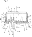
- FIG. 1 is a view schematically illustrating a cross section of an upper portion of a compressor according to an embodiment of the present disclosure, taken along a vertical plane.
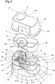
- FIG. 2 is a view illustrating a state in which the upper portion of the compressor is disassembled, as viewed obliquely from above.
- the compressor includes a hermetic container 1 that contains, for example, a metal, a terminal 2 that is provided to the hermetic container 1, a terminal guard 3 that contains, for example, a metal, a rubber member 4, and a terminal cover 5.
- the hermetic container 1 is an example of a casing.
- the rubber member 4 is an example of an insulating member.
- the upper portion of the hermetic container 1 is curved so as to project to the outside (see FIG. 4 ).
- a raised portion 11 to which the terminal 2 is mounted is provided in the upper portion of the hermetic container 1.
- a compression mechanism unit (not illustrated) is disposed in the lower area of the hermetic container 1.
- a motor (not illustrated) that drives the compression mechanism unit is disposed in the upper area of the hermetic container 1.
- a high-pressure fluid for example, a refrigerant
- a discharge pipe 12 is inserted near the center of the upper portion of the hermetic container 1.
- the discharge pipe 12 extends in the vertical direction and guides the high-pressure fluid in the hermetic container 1 to the outside of the hermetic container 1.
- the terminal 2 is a hermetic terminal (airtight terminal). More specifically, the terminal 2 includes a body section 21 that contains, for example, a metal, and, for example, three terminal rods 22 that are inserted through the body section 21.
- the body section 21 contains a metal material and is formed into a container shape.
- the body section 21 is fitted into a through hole 11a of the raised portion 11 and then fixed to a peripheral edge portion of the through hole 11a by, for example, welding. At this time, part of the body section 21 projects above the upper surface of the raised portion 11, and a step is formed between the upper end surface of the body section 21 and the outer surface of the raised portion 11.
- the body section 21 includes a base section 211 having a disc shape and provided on the upper end side of the body section 21.
- a through hole 211a through which the terminal rod 22 is inserted is formed in the base section 211.
- the gap between the outer peripheral surface of the terminal rod 22 and the inner peripheral surface of the through hole 211a is filled with an insulating glass portion 23 containing glass.
- the insulating glass portion 23 fixes the terminal rod 22 to the body section 21 and insulates the body section 21 from the terminal rod 22.
- the body section 21 further includes a cylindrical section 212 whose upper end is continuous to the base section 211.
- the diameter of the lower end portion of the cylindrical section 212 increases as proceeding to the inner side of the hermetic container 1. That is, the cylindrical section 212 is formed so that the lower end portion thereof engages with the peripheral edge portion of the through hole 11a. As a result, it is possible to reduce the possibility that the body section 21 comes off from the hermetic container 1 when pressure is applied from the fluid inside the hermetic container 1.
- the terminal rod 22 has one end portion located outside the hermetic container 1 and the other end portion located inside the hermetic container 1.
- a terminal plate 24 provided at the one end portion of the terminal rod 22 is electrically connected to the power source via wiring L (illustrated in FIG. 4 ).
- a current from the power source flows through the terminal rod 22 and then is supplied to the motor through wiring (not illustrated) in the hermetic container 1.
- the material of each of the terminal rod 22 and the terminal plate 24 may be any material that has conductivity.
- the terminal guard 3 is provided outside the hermetic container 1 so as to surround the terminal 2. More specifically, the terminal guard 3 includes a bottom plate 31 and a side wall 32 extending upward from a peripheral edge portion of the bottom plate 31.
- a through hole 31a through which the body section 21 is inserted is formed in the bottom plate 31.
- the diameter of the through hole 31a is set to be larger than the diameter of the upper end portion of the cylindrical section 212.
- the side wall 32 is disposed so as to face the terminal rod 22 in the radial direction. That is, the side wall 32 is located on a lateral side of the terminal rod 22.
- First and second cutouts 33 and 34 and first to fourth through holes 35 to 38 are formed in the side wall 32.
- a concave portion 39 that is recessed inward is provided in a portion of the side wall 32 on a discharge pipe 12 side. The concave portion 39 is located under the second cutout 34 and is located on a lateral side of the discharge pipe 12.
- a closing member 6 that contains, for example, heat resistant rubber is mounted to the first cutout 33.
- the closing member 6 has a through hole 6a through which the wiring L is inserted and a cut 6b.
- the cut 6b extends from one side of the outer peripheral edge of the closing member 6 to the through hole 6a. As a result, it is possible to insert part of the wiring L into the through hole 6a through the cut 6b.
- a groove 6c is formed in a peripheral edge portion of the closing member 6 over the entire circumference.
- the first cutout 33 is fitted into the groove 6c, and the closing member 6 is mounted to the terminal guard 3.
- the rubber member 4 is disposed in the terminal guard 3.
- the rubber member 4 includes a bottom section 41 and a side section 42 integrally provided in an erected manner on a peripheral edge portion of the bottom section 41.
- the rubber member 4 contains silicon rubber so that the thickness thereof is, for example, 3.0 mm.
- the bottom section 41 covers an area other than the through hole 211a of the body section 21 and an area around the body section 21.
- a through hole 41a through which the terminal rod 22 is inserted is formed in the bottom section 41.
- the diameter of the through hole 41a is set to be identical to the diameter of the insulating glass portion 23. That is, only the insulating glass portion 23 is exposed from the through hole 41a.
- the diameter of the through hole 41a is set to be slightly smaller than the maximum width (the maximum length in the direction parallel to the radial direction of the terminal rod 22) of the terminal plate 24 of the terminal 2. At this time, the value obtained by subtracting the diameter of the through hole 41a from the maximum width of the terminal plate 24 of the terminal 2 is, for example, is 0.8 mm or less.
- the bottom section 41 is formed along the upper surface of the body section 21 and the upper surface of the bottom plate 31 of the terminal guard 3. As a result, it is possible to suppress rattling of the rubber member 4 when the rubber member 4 is disposed in the terminal guard 3.
- the side section 42 has a height H1 identical to a height H2 of the side wall 32 of the terminal guard 3, and covers most of the inner surface of the side wall 32 of the terminal guard 3. At this time, a gap is formed over the entire circumference between the outer surface of the side section 42 and the inner surface of the side wall 32. Note that each of the heights H1 and H2 means the height with respect to the surface (the outer surface of the raised portion 11) on which the terminal guard 3 is to be mounted.
- a concave portion 43 that is recessed inward is provided in a portion of the side section 42 on a discharge pipe 12 side.
- the rubber member 4 is disposed in the terminal guard 3 so that the concave portion 43 faces the concave portion 39 of the terminal guard 3. At this time, part of the concave portion 43 of the rubber member 4 is exposed from the second cutout 34 of the terminal guard 3 and faces the discharge pipe 12 in the radial direction (see FIG. 3 ).
- the compressor further includes a terminal chamber 7 defined by the hermetic container 1 and the terminal guard 3. 90% or more of the surface area of a metal portion facing the terminal chamber 7 is covered with the rubber member 4. Note that the metal portion does not include the terminal rods 22.
- the terminal cover 5 includes a top section 51 and a side section 52 extending downward from a peripheral edge portion of the top section 51, and covers the terminal 2, the terminal guard 3, and the rubber member 4.
- the terminal cover 5 contains nylon 66 so as to have a thickness of 1.5 mm, for example. Note that the terminal cover 5 preferably complies with the UL94-5VA standard.
- First and second raised portions 53 and 54 which are inserted into the first and second through holes 35 and 36 are formed on the inner peripheral surface of the side section 52.
- Third and fourth raised portions (not illustrated) which are inserted into the third and fourth through holes 37 and 38 are provided on other portions of the inner peripheral surface of the side section 52.
- a concave portion 55 that is recessed inward is provided in a portion of the side section 52 on a discharge pipe 12 side.
- the concave portion 55 faces the discharge pipe 12 in the radial direction when the terminal cover 5 covers the terminal 2 and the like. At this time, the concave portion 55 is located between the concave portion 39 of the terminal guard 3 and the discharge pipe 12.
- a cutout 56 is provided in a portion of the side section 52 on the side opposite to the discharge pipe 12.
- the terminal cover 5 includes a flange section 57 that laterally projects from the lower end portion of the side section 52.
- the lower end of the flange section 57 is disposed below the surface on which the terminal guard 3 is to be mounted.
- FIG. 3 is a view illustrating a state in which the rubber member 4 is disposed in the terminal guard 3 as viewed obliquely from above.
- the side section 42 of the rubber member 4 is not provided over the entire circumference of the peripheral edge portion of the bottom section 41.
- the area without the side section 42 faces the first cutout 33 of the terminal guard 3 when the rubber member 4 is disposed in the terminal guard 3.
- a width D1 of the area without the side section 42 is greater than a width D2 of the first cutout 33. Therefore, only the area adjacent to the first cutout 33 on the inner surface of the side wall 32 of the terminal guard 3 is exposed without being covered by the side section 42.
- each of the widths D1 and D2 means the length in the direction along the edge portion on the side opposite to the discharge pipe 12 in the peripheral edge portion of the bottom section 41.
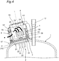
- FIG. 4 is a sectional view taken along line IV-IV in FIG. 1 .
- the surface on which the terminal guard 3 is to be mounted is inclined with respect to the horizontal direction. Therefore, when the terminal guard 3 is mounted on the surface on which the terminal guard 3 is to be mounted, a portion on a closing member 6 side is lower than a portion of on a discharge pipe 12 side on the bottom plate 31 of the terminal guard 3.
- the side section 42 of the rubber member 4 covers the inner surface of the side wall 32 of the terminal guard 3. Therefore, the side section 42 is located inside the terminal guard 3 and not located outside the terminal guard 3. Therefore, even if, for example, water flows near the side wall 32 of the terminal guard 3 on the outside of the terminal guard 3, the water is not retained by the upper end portion of the side section 42 of the rubber member 4. As a result, it is possible to reduce the risk that the water enters the inside of the terminal guard 3 from the outside to contact the terminal. That is, it is possible to reduce the risk of a short-circuit in the terminal 2.
- the side section 42 of the rubber member 4 covers the inner surface of the side wall 32 of the terminal guard 3. Therefore, even if the terminal rod 22 comes off from the body section 21 and the entire terminal rod 22 is located in the terminal chamber 7, it is possible to reduce the possibility that the terminal rod 22 contacts the inner surface of the side wall 32 of the terminal guard 3. Therefore, it is possible to suppress generation of sparks due to contact between the terminal rod 22 and the inner surface of the side wall 32 of the terminal guard 3.
- the side section 42 is provided integrally with and erected on the peripheral edge portion of the bottom section 41, there is no gap between the bottom section 41 and the side section 42. Therefore, even if, for example, water enters the inside of the terminal guard 3, it is possible to prevent the water from entering the inside of the rubber member 4. As a result, the effect of reducing the risk of a short circuit in the terminal 2 can be enhanced.
- the height H1 of the side section of the rubber member 4 is identical to the height H1 of the side wall of the terminal guard 3. Therefore, even if the terminal rod 22 moves toward the side wall 32 of the terminal guard 3 when the terminal rod 22 comes off from the body section 21, the possibility that the terminal rod 22 contacts the inner surface of the side wall 32 of the terminal guard 3 can be surely greatly reduced.
- the diameter of the through hole 41a of the bottom section 41 of the rubber member 4 is set to be identical to the diameter of the insulating glass portion 23, it is possible to reliably cover the area of the body section 21 other than the through hole 211a. Therefore, it is possible to reduce the possibility of contacting the area of the body section 21 other than the through hole 211a when the terminal rod 22 comes off from the body section 21.
- a gap is formed over the entire circumference between the side wall 32 of the terminal guard 3 and the side section 42 of the rubber member 4.
- the gap may not be formed.
- at least part of the side section 42 of the rubber member 4 may be in close contact with the side wall 32 of the terminal guard 3.
- the height of the side section 42 of the rubber member 4 is identical to the height of the side wall of the terminal guard 3.
- the height of the side section 42 may be higher than the height of the side wall of the terminal guard 3.
- the height of the side wall of the terminal guard 3 can be increased up to the height at which the side wall contacts the terminal cover 5.
- the height of the side section 42 of the rubber member 4 is identical to the height of the side wall of the terminal guard 3.
- the height of the side section 42 may be slightly lower than the height of the side wall of the terminal guard 3 or may be a little higher than the height of the side wall of the terminal guard 3 due to, for example, manufacturing error.
- the value obtained by subtracting the height of the side wall of the terminal guard 3 from the height of the side section 42 of the rubber member 4 falls within a range of, for example, -1.6 mm to 1.0 mm.
- the terminal plate 24 is provided at the one end portion of the terminal rod 22.
- the terminal plate 24 may not be provided at the one end portion of the terminal rod 22.
- the diameter of the through hole 41a of the bottom section 41 of the rubber member 4 may be equal to or larger than the diameter of the insulating glass portion 23 or equal to or less than the diameter of the terminal rod 22.
- the diameter of the through hole 41a in the bottom section 41 of the rubber member 4 may be set to be identical to the maximum width of the terminal plate 24 of the terminal 2, or slightly smaller than the maximum width of the terminal plate 24 of the terminal 2.
- the value obtained by subtracting the maximum width of the terminal plate 24 of the terminal 2 from the diameter of the through hole 41a is, for example, is 0.0 mm or more and 0.8 mm or less.
- the diameter of the through hole 41a in the bottom section 41 of the rubber member 4 is identical to the diameter of the insulating glass portion 23.
- the diameter of the through hole 41a may be slightly smaller than the diameter of the insulating glass portion 23, or may be slightly larger than the diameter of the insulating glass portion 23 due to manufacturing error, or the like.
- the value obtained by subtracting the diameter of the insulating glass portion 23 from the diameter of the through hole 41a falls within the range of -2.0 mm to 2.0 mm, for example.
- the bottom section 41 of the rubber member 4 covers the area other than the through hole 211a of the body section 21 and the area around the body section 21.
- the bottom section 41 may cover only the area around the body section 21.
- Examples of a compressor to which a terminal structure including the rubber member 4 and the like is applied include a scroll compressor, a rotary compressor, a swing compressor, and the like. That is, the terminal structure can be applied to various types of compressors.
- the compressor may be a so-called one-cylinder compressor or a so-called two-cylinder compressor.
Landscapes
- Engineering & Computer Science (AREA)
- Mechanical Engineering (AREA)
- General Engineering & Computer Science (AREA)
- Power Engineering (AREA)
- Compressor (AREA)
- Motor Or Generator Frames (AREA)
- Connections Arranged To Contact A Plurality Of Conductors (AREA)
Abstract
Description
- The present disclosure relates to compressors.
- Conventionally, a compressor includes a terminal that is provided to a casing, an overload relay that is provided to the casing and adjacent to the terminal, and a terminal cover that covers the terminal and the overload relay (for example, see
JP S63-123784 U - A gasket is disposed between the casing and the terminal cover. A protrusion that extends along a peripheral edge of the gasket is provided on an upper surface of this gasket. The protrusion is located closer to the peripheral edge of the gasket than a side wall of the terminal cover is and is in contact with an outer surface of the side wall.
- Patent Literature 1:
JP S63-123784 U - In the above-described conventional compressor, since the protrusion is disposed outside the side wall of the terminal cover, for example, water is retained on an apical end surface of the protrusion. As a result, there is a possibility that water outside the terminal cover enters the inside of the terminal cover through the gap between the protrusion and the side wall of the terminal cover.
- Therefore, the conventional compressor has a problem in that water that has entered the inside of the terminal cover contacts the terminal, which causes a short circuit in the terminal.
- The present disclosure aims to provide a compressor that can reduce the risk of a short circuit in a terminal.
- A compressor according to the present disclosure includes
a casing,
a terminal that is provided to the casing and includes a body section and a terminal rod inserted through the body section,
a terminal guard that is provided outside the casing to surround the terminal, and includes a side wall facing the terminal rod in the radial direction, and
an insulating member that is disposed inside the terminal guard,
in which the insulating member includes
a bottom section that covers an area around the body section, and
a side section that is integrally provided in an erected manner on a peripheral edge portion of the bottom section and covers an inner surface of the side wall of the terminal guard. - According to the above-described configuration, since the side section of the insulating member covers the inner surface of the side wall of the terminal guard, the risk of a short circuit in the terminal can be reduced.
- In one aspect of the compressor,
the height of the side section of the insulating member is substantially identical to the height of the side wall of the terminal guard. - Here, the case where the height of the side section of the insulating member is substantially identical to the height of the side wall of the terminal guard includes not only a case where the height of the side section of the insulating member is identical to the height of the side wall of the terminal guard, but also includes a case where the height of the side section of the insulating member is slightly higher than the height of the side wall of the terminal guard or slightly lower than the height of the side wall of the terminal guard due to a manufacturing error, for example.
- Furthermore, in the case where the height of the side section of the insulating member is slightly higher than the height of the side wall of the terminal guard, the value obtained by subtracting the height of the side wall of the terminal guard from the height of the side section of the insulating member is, for example, 1.0 mm or less.
- Furthermore, in the case where the height of the side section of the insulating member is slightly lower than the height of the side wall of the terminal guard, the value obtained by subtracting the height of the side section of the insulating member from the height of the side wall of the terminal guard is, for example, 1.6 mm or less.
- According to the aspect, it is possible to reduce the possibility that the terminal rod contacts the side wall of the terminal guard when the terminal rod comes off from the body section.
- In one aspect of the compressor,
a terminal chamber is defined by the casing and the terminal guard, and
90% or more of a surface area of a metal portion facing the terminal chamber is covered with the insulating member. - Here, the metal portion means a metal portion other than the terminal rod, the metal portion facing the terminal chamber.
- According to the aspect, it is possible to reduce the possibility that the terminal rod contacts the metal portion facing the terminal chamber when the terminal rod comes off from the body section.
- In one aspect of the compressor,
a through hole through which the terminal rod is inserted is provided in the body section,
an insulating glass portion containing glass is provided between an outer peripheral surface of the terminal rod and an inner peripheral surface of the through hole,
the bottom section of the insulating member has a through hole through which the terminal rod is inserted, and covers the body section, and
a diameter of the through hole in the bottom section of the insulating member is substantially identical to a diameter of the insulating glass portion. - Here, the case where the diameter of the through hole in the bottom section of the insulating member is substantially identical to the diameter of the insulating glass portion includes not only a case where the diameter of the through hole in the bottom section of the insulating member is identical to the diameter of the insulating glass portion, but also a case where the diameter of the through hole in the bottom section of the insulating member is slightly smaller than the diameter of the insulating glass portion, or the diameter of the through hole in the bottom of the insulating member is slightly larger than the diameter of the insulating glass portion.
- Furthermore, in the case where the diameter of the through hole in the bottom section of the insulating member is slightly smaller than the diameter of the insulating glass portion, the value obtained by subtracting the diameter of the through hole in the bottom section of the insulating member from the diameter of the insulating glass portion is, for example, 2.0 mm or less.
- Furthermore, in the case where the diameter of the through hole in the bottom section of the insulating member is slightly larger than the diameter of the insulating glass portion, the value obtained by subtracting the diameter of the insulating glass portion from the diameter of the through hole in the bottom section of the insulating member is, for example, 2.0 mm or less.
- According to the aspect, it is possible to reduce the possibility that the terminal rod contacts the body section when the terminal rod comes off from the body section.
-
-
FIG. 1 is a partial sectional view of a compressor according to an embodiment. -
FIG. 2 is an exploded perspective view of part of the compressor. -
FIG. 3 is a perspective view of a terminal of the compressor and a peripheral portion thereof. -
FIG. 4 is a sectional view taken along line IV-IV inFIG. 1 . - Hereinafter, an illustrated embodiment will be described in detail. Note that in the drawings, identical reference numerals represent identical parts.
-
FIG. 1 is a view schematically illustrating a cross section of an upper portion of a compressor according to an embodiment of the present disclosure, taken along a vertical plane.FIG. 2 is a view illustrating a state in which the upper portion of the compressor is disassembled, as viewed obliquely from above. - As illustrated in
FIGS. 1 and2 , the compressor includes ahermetic container 1 that contains, for example, a metal, aterminal 2 that is provided to thehermetic container 1, aterminal guard 3 that contains, for example, a metal, arubber member 4, and aterminal cover 5. Note that thehermetic container 1 is an example of a casing. Therubber member 4 is an example of an insulating member. - The upper portion of the
hermetic container 1 is curved so as to project to the outside (seeFIG. 4 ). A raisedportion 11 to which theterminal 2 is mounted is provided in the upper portion of thehermetic container 1. A compression mechanism unit (not illustrated) is disposed in the lower area of thehermetic container 1. In contrast, a motor (not illustrated) that drives the compression mechanism unit is disposed in the upper area of thehermetic container 1. When this motor drives the compression mechanism unit, a high-pressure fluid (for example, a refrigerant) compressed by the compression mechanism unit fills thehermetic container 1. - A
discharge pipe 12 is inserted near the center of the upper portion of thehermetic container 1. Thedischarge pipe 12 extends in the vertical direction and guides the high-pressure fluid in thehermetic container 1 to the outside of thehermetic container 1. - The
terminal 2 is a hermetic terminal (airtight terminal). More specifically, theterminal 2 includes abody section 21 that contains, for example, a metal, and, for example, threeterminal rods 22 that are inserted through thebody section 21. - For example, the
body section 21 contains a metal material and is formed into a container shape. Thebody section 21 is fitted into a throughhole 11a of the raisedportion 11 and then fixed to a peripheral edge portion of the throughhole 11a by, for example, welding. At this time, part of thebody section 21 projects above the upper surface of the raisedportion 11, and a step is formed between the upper end surface of thebody section 21 and the outer surface of the raisedportion 11. - The
body section 21 includes abase section 211 having a disc shape and provided on the upper end side of thebody section 21. A throughhole 211a through which theterminal rod 22 is inserted is formed in thebase section 211. The gap between the outer peripheral surface of theterminal rod 22 and the inner peripheral surface of the throughhole 211a is filled with an insulatingglass portion 23 containing glass. The insulatingglass portion 23 fixes theterminal rod 22 to thebody section 21 and insulates thebody section 21 from theterminal rod 22. - The
body section 21 further includes acylindrical section 212 whose upper end is continuous to thebase section 211. The diameter of the lower end portion of thecylindrical section 212 increases as proceeding to the inner side of thehermetic container 1. That is, thecylindrical section 212 is formed so that the lower end portion thereof engages with the peripheral edge portion of the throughhole 11a. As a result, it is possible to reduce the possibility that thebody section 21 comes off from thehermetic container 1 when pressure is applied from the fluid inside thehermetic container 1. - A current from a power source (not illustrated) outside the
hermetic container 1 flows through theterminal rod 22. Theterminal rod 22 has one end portion located outside thehermetic container 1 and the other end portion located inside thehermetic container 1. Aterminal plate 24 provided at the one end portion of theterminal rod 22 is electrically connected to the power source via wiring L (illustrated inFIG. 4 ). A current from the power source flows through theterminal rod 22 and then is supplied to the motor through wiring (not illustrated) in thehermetic container 1. Note that the material of each of theterminal rod 22 and theterminal plate 24 may be any material that has conductivity. - The
terminal guard 3 is provided outside thehermetic container 1 so as to surround theterminal 2. More specifically, theterminal guard 3 includes abottom plate 31 and aside wall 32 extending upward from a peripheral edge portion of thebottom plate 31. - A through
hole 31a through which thebody section 21 is inserted is formed in thebottom plate 31. The diameter of the throughhole 31a is set to be larger than the diameter of the upper end portion of thecylindrical section 212. Thus, when thebody section 21 is inserted into the throughhole 31a of thebottom plate 31, a gap is generated between the outer peripheral surface of the upper end portion of thecylindrical section 212 and the inner peripheral surface of the throughhole 31a. - The
side wall 32 is disposed so as to face theterminal rod 22 in the radial direction. That is, theside wall 32 is located on a lateral side of theterminal rod 22. First andsecond cutouts holes 35 to 38 are formed in theside wall 32. Aconcave portion 39 that is recessed inward is provided in a portion of theside wall 32 on adischarge pipe 12 side. Theconcave portion 39 is located under thesecond cutout 34 and is located on a lateral side of thedischarge pipe 12. - A closing
member 6 that contains, for example, heat resistant rubber is mounted to thefirst cutout 33. The closingmember 6 has a throughhole 6a through which the wiring L is inserted and acut 6b. Thecut 6b extends from one side of the outer peripheral edge of the closingmember 6 to the throughhole 6a. As a result, it is possible to insert part of the wiring L into the throughhole 6a through thecut 6b. - Further, a
groove 6c is formed in a peripheral edge portion of the closingmember 6 over the entire circumference. Thefirst cutout 33 is fitted into thegroove 6c, and the closingmember 6 is mounted to theterminal guard 3. - The
rubber member 4 is disposed in theterminal guard 3. Therubber member 4 includes abottom section 41 and aside section 42 integrally provided in an erected manner on a peripheral edge portion of thebottom section 41. Therubber member 4 contains silicon rubber so that the thickness thereof is, for example, 3.0 mm. - The
bottom section 41 covers an area other than the throughhole 211a of thebody section 21 and an area around thebody section 21. A throughhole 41a through which theterminal rod 22 is inserted is formed in thebottom section 41. The diameter of the throughhole 41a is set to be identical to the diameter of the insulatingglass portion 23. That is, only the insulatingglass portion 23 is exposed from the throughhole 41a. The diameter of the throughhole 41a is set to be slightly smaller than the maximum width (the maximum length in the direction parallel to the radial direction of the terminal rod 22) of theterminal plate 24 of theterminal 2. At this time, the value obtained by subtracting the diameter of the throughhole 41a from the maximum width of theterminal plate 24 of theterminal 2 is, for example, is 0.8 mm or less. - The
bottom section 41 is formed along the upper surface of thebody section 21 and the upper surface of thebottom plate 31 of theterminal guard 3. As a result, it is possible to suppress rattling of therubber member 4 when therubber member 4 is disposed in theterminal guard 3. - The
side section 42 has a height H1 identical to a height H2 of theside wall 32 of theterminal guard 3, and covers most of the inner surface of theside wall 32 of theterminal guard 3. At this time, a gap is formed over the entire circumference between the outer surface of theside section 42 and the inner surface of theside wall 32. Note that each of the heights H1 and H2 means the height with respect to the surface (the outer surface of the raised portion 11) on which theterminal guard 3 is to be mounted. - A
concave portion 43 that is recessed inward is provided in a portion of theside section 42 on adischarge pipe 12 side. Therubber member 4 is disposed in theterminal guard 3 so that theconcave portion 43 faces theconcave portion 39 of theterminal guard 3. At this time, part of theconcave portion 43 of therubber member 4 is exposed from thesecond cutout 34 of theterminal guard 3 and faces thedischarge pipe 12 in the radial direction (seeFIG. 3 ). - The compressor further includes a
terminal chamber 7 defined by thehermetic container 1 and theterminal guard 3. 90% or more of the surface area of a metal portion facing theterminal chamber 7 is covered with therubber member 4. Note that the metal portion does not include theterminal rods 22. - The
terminal cover 5 includes atop section 51 and aside section 52 extending downward from a peripheral edge portion of thetop section 51, and covers theterminal 2, theterminal guard 3, and therubber member 4. Theterminal cover 5 contains nylon 66 so as to have a thickness of 1.5 mm, for example. Note that theterminal cover 5 preferably complies with the UL94-5VA standard. - First and second raised
portions holes side section 52. Third and fourth raised portions (not illustrated) which are inserted into the third and fourth throughholes side section 52. - A
concave portion 55 that is recessed inward is provided in a portion of theside section 52 on adischarge pipe 12 side. Theconcave portion 55 faces thedischarge pipe 12 in the radial direction when theterminal cover 5 covers theterminal 2 and the like. At this time, theconcave portion 55 is located between theconcave portion 39 of theterminal guard 3 and thedischarge pipe 12. - A
cutout 56 is provided in a portion of theside section 52 on the side opposite to thedischarge pipe 12. When theterminal cover 5 covers theterminal 2 and the like, the closingmember 6 is exposed from thecutout 56. - The
terminal cover 5 includes aflange section 57 that laterally projects from the lower end portion of theside section 52. The lower end of theflange section 57 is disposed below the surface on which theterminal guard 3 is to be mounted. -
FIG. 3 is a view illustrating a state in which therubber member 4 is disposed in theterminal guard 3 as viewed obliquely from above. - The
side section 42 of therubber member 4 is not provided over the entire circumference of the peripheral edge portion of thebottom section 41. The area without theside section 42 faces thefirst cutout 33 of theterminal guard 3 when therubber member 4 is disposed in theterminal guard 3. At this time, a width D1 of the area without theside section 42 is greater than a width D2 of thefirst cutout 33. Therefore, only the area adjacent to thefirst cutout 33 on the inner surface of theside wall 32 of theterminal guard 3 is exposed without being covered by theside section 42. Note that each of the widths D1 and D2 means the length in the direction along the edge portion on the side opposite to thedischarge pipe 12 in the peripheral edge portion of thebottom section 41. -
FIG. 4 is a sectional view taken along line IV-IV inFIG. 1 . - The surface on which the
terminal guard 3 is to be mounted is inclined with respect to the horizontal direction. Therefore, when theterminal guard 3 is mounted on the surface on which theterminal guard 3 is to be mounted, a portion on a closingmember 6 side is lower than a portion of on adischarge pipe 12 side on thebottom plate 31 of theterminal guard 3. - According to the compressor configured as described above, the
side section 42 of therubber member 4 covers the inner surface of theside wall 32 of theterminal guard 3. Therefore, theside section 42 is located inside theterminal guard 3 and not located outside theterminal guard 3. Therefore, even if, for example, water flows near theside wall 32 of theterminal guard 3 on the outside of theterminal guard 3, the water is not retained by the upper end portion of theside section 42 of therubber member 4. As a result, it is possible to reduce the risk that the water enters the inside of theterminal guard 3 from the outside to contact the terminal. That is, it is possible to reduce the risk of a short-circuit in theterminal 2. - Further, the
side section 42 of therubber member 4 covers the inner surface of theside wall 32 of theterminal guard 3. Therefore, even if theterminal rod 22 comes off from thebody section 21 and the entireterminal rod 22 is located in theterminal chamber 7, it is possible to reduce the possibility that theterminal rod 22 contacts the inner surface of theside wall 32 of theterminal guard 3. Therefore, it is possible to suppress generation of sparks due to contact between theterminal rod 22 and the inner surface of theside wall 32 of theterminal guard 3. - Further, in the
rubber member 4, since theside section 42 is provided integrally with and erected on the peripheral edge portion of thebottom section 41, there is no gap between thebottom section 41 and theside section 42. Therefore, even if, for example, water enters the inside of theterminal guard 3, it is possible to prevent the water from entering the inside of therubber member 4. As a result, the effect of reducing the risk of a short circuit in theterminal 2 can be enhanced. - Furthermore, the height H1 of the side section of the
rubber member 4 is identical to the height H1 of the side wall of theterminal guard 3. Therefore, even if theterminal rod 22 moves toward theside wall 32 of theterminal guard 3 when theterminal rod 22 comes off from thebody section 21, the possibility that theterminal rod 22 contacts the inner surface of theside wall 32 of theterminal guard 3 can be surely greatly reduced. - Furthermore, when the
terminal rod 22 comes off from thebody section 21, even if theterminal rod 22 moves in various directions in theterminal chamber 7, since 90% or more of the surface area of the metal portion facing theterminal chamber 7 is covered with therubber member 4, the possibility that theterminal rod 22 contacts the metal portion can be reduced. - Moreover, since the diameter of the through
hole 41a of thebottom section 41 of therubber member 4 is set to be identical to the diameter of the insulatingglass portion 23, it is possible to reliably cover the area of thebody section 21 other than the throughhole 211a. Therefore, it is possible to reduce the possibility of contacting the area of thebody section 21 other than the throughhole 211a when theterminal rod 22 comes off from thebody section 21. - Even if water enters the inside of the
terminal guard 3, since thebottom plate 31 of theterminal guard 3 is inclined such that the portion on the closingmember 6 side is lower than the portion on thedischarge pipe 12 side, the water can be discharged to the outside of theterminal guard 3 from a gap such as the throughhole 6a, the throughhole 6a, or the like. - In the above-described embodiment, a gap is formed over the entire circumference between the
side wall 32 of theterminal guard 3 and theside section 42 of therubber member 4. However, for example, the gap may not be formed. For example, at least part of theside section 42 of therubber member 4 may be in close contact with theside wall 32 of theterminal guard 3. - In the above-described embodiment, the height of the
side section 42 of therubber member 4 is identical to the height of the side wall of theterminal guard 3. However, for example, the height of theside section 42 may be higher than the height of the side wall of theterminal guard 3. In this case, the height of the side wall of theterminal guard 3 can be increased up to the height at which the side wall contacts theterminal cover 5. - In the above-described embodiment, the height of the
side section 42 of therubber member 4 is identical to the height of the side wall of theterminal guard 3. However, for example, the height of theside section 42 may be slightly lower than the height of the side wall of theterminal guard 3 or may be a little higher than the height of the side wall of theterminal guard 3 due to, for example, manufacturing error. In such a case, the value obtained by subtracting the height of the side wall of theterminal guard 3 from the height of theside section 42 of therubber member 4 falls within a range of, for example, -1.6 mm to 1.0 mm. - In the above-described embodiment, the
terminal plate 24 is provided at the one end portion of theterminal rod 22. However, for example, theterminal plate 24 may not be provided at the one end portion of theterminal rod 22. In such a case, for example, the diameter of the throughhole 41a of thebottom section 41 of therubber member 4 may be equal to or larger than the diameter of the insulatingglass portion 23 or equal to or less than the diameter of theterminal rod 22. - In the above-described embodiment, for example, the diameter of the through
hole 41a in thebottom section 41 of therubber member 4 may be set to be identical to the maximum width of theterminal plate 24 of theterminal 2, or slightly smaller than the maximum width of theterminal plate 24 of theterminal 2. In such a case, the value obtained by subtracting the maximum width of theterminal plate 24 of the terminal 2 from the diameter of the throughhole 41a is, for example, is 0.0 mm or more and 0.8 mm or less. - In the above-described embodiment, the diameter of the through
hole 41a in thebottom section 41 of therubber member 4 is identical to the diameter of the insulatingglass portion 23. However, for example, the diameter of the throughhole 41a may be slightly smaller than the diameter of the insulatingglass portion 23, or may be slightly larger than the diameter of the insulatingglass portion 23 due to manufacturing error, or the like. In such a case, the value obtained by subtracting the diameter of the insulatingglass portion 23 from the diameter of the throughhole 41a falls within the range of -2.0 mm to 2.0 mm, for example. - In the above-described embodiment, the
bottom section 41 of therubber member 4 covers the area other than the throughhole 211a of thebody section 21 and the area around thebody section 21. However, for example, thebottom section 41 may cover only the area around thebody section 21. - The foregoing description concerns a specific embodiment of the present disclosure; however, the present disclosure is not limited to the above-described embodiment and modifications, and various modifications and variations may be made within the scope of the present disclosure. For example, an appropriate combination of the configurations described in the above-described embodiment and modifications may be regarded as an embodiment of the present disclosure.
- Examples of a compressor to which a terminal structure including the
rubber member 4 and the like is applied include a scroll compressor, a rotary compressor, a swing compressor, and the like. That is, the terminal structure can be applied to various types of compressors. - Further, for example, the compressor may be a so-called one-cylinder compressor or a so-called two-cylinder compressor.
-
- 1
- hermetic container
- 2
- terminal
- 3
- terminal guard
- 4
- rubber member
- 5
- terminal cover
- 7
- terminal chamber
- 11
- raised portion
- 11a
- through hole
- 12
- discharge pipe
- 21
- body section
- 22
- terminal rod
- 24
- terminal plate
- 31
- bottom plate
- 31a
- through hole
- 32
- side wall
- 33
- first cutout
- 34
- second cutout
- 35
- first through hole
- 36
- second through hole
- 37
- third through hole
- 38
- fourth through hole
- 41
- bottom section
- 42
- side section
- 41a
- through hole
- 51
- top section
- 52
- side section
- 55
- concave portion
- 56
- cutout
- 211
- base section
- 211a
- through hole
- 212
- cylindrical section
- L
- wiring
- D1, D2
- width
- H1, H2
- height
Claims (4)
- A compressor comprising:a casing (1);a terminal (2) that is provided to the casing (1) and includes a body section (21) and a terminal rod (22) inserted through the body section (21);a terminal guard (3) that is provided outside the casing (1) to surround the terminal, and includes a side wall (32) facing the terminal rod (22) in a radial direction; andan insulating member (4) that is disposed inside the terminal guard (3),wherein the insulating member (4) includesa bottom section (41) that covers an area around the body section (21), anda side section (42) that is integrally provided in an erected manner on a peripheral edge portion of the bottom section (41) and covers an inner surface of the side wall (32) of the terminal guard (3).
- The compressor according to claim 1, wherein a height (H1) of the side section (42) of the insulating member (4) is substantially identical to a height (H2) of the side wall (32) of the terminal guard (3).
- The compressor according to claim 1 or 2, wherein
a terminal chamber (7) is defined by the casing (1) and the terminal guard (3),
90% or more of a surface area of a metal portion that faces the terminal chamber (7) is covered with the insulating member (4). - The compressor according to any one of claims 1 to 3, wherein
a through hole (211a) through which the terminal rod (22) is inserted is formed in the body section (21),
an insulating glass portion (23) that contains glass is provided between an outer peripheral surface of the terminal rod (22) and an inner peripheral surface of the through hole (211a),
the bottom section (41) of the insulating member (4) has a through hole (41a) through which the terminal rod (22) is inserted, and covers the body section (21), and
a diameter of the through hole (41a) in the bottom section (41) of the insulating member (4) is substantially identical to a diameter of the insulating glass portion (23) .
Applications Claiming Priority (2)
| Application Number | Priority Date | Filing Date | Title |
|---|---|---|---|
| JP2018057675A JP6624225B2 (en) | 2018-03-26 | 2018-03-26 | Compressor |
| PCT/JP2019/001837 WO2019187541A1 (en) | 2018-03-26 | 2019-01-22 | Compressor |
Publications (3)
| Publication Number | Publication Date |
|---|---|
| EP3754193A1 true EP3754193A1 (en) | 2020-12-23 |
| EP3754193A4 EP3754193A4 (en) | 2020-12-23 |
| EP3754193B1 EP3754193B1 (en) | 2021-09-22 |
Family
ID=68059871
Family Applications (1)
| Application Number | Title | Priority Date | Filing Date |
|---|---|---|---|
| EP19778367.3A Active EP3754193B1 (en) | 2018-03-26 | 2019-01-22 | Compressor |
Country Status (6)
| Country | Link |
|---|---|
| US (1) | US11451110B2 (en) |
| EP (1) | EP3754193B1 (en) |
| JP (1) | JP6624225B2 (en) |
| CN (1) | CN111757984B (en) |
| ES (1) | ES2895059T3 (en) |
| WO (1) | WO2019187541A1 (en) |
Families Citing this family (3)
| Publication number | Priority date | Publication date | Assignee | Title |
|---|---|---|---|---|
| CN112713696A (en) * | 2020-12-29 | 2021-04-27 | 中车永济电机有限公司 | Space-saving and convenient-to-disassemble motor junction box |
| CN116123054A (en) * | 2021-11-12 | 2023-05-16 | 上海海立电器有限公司 | Waterproof protective sleeve structure for compressor and compressor comprising waterproof protective sleeve structure |
| WO2024121605A1 (en) * | 2022-12-08 | 2024-06-13 | Siam Compressor Industry Co., Ltd. | Terminal cover structure for compressor, compressor and method for manufacturing compressor |
Family Cites Families (15)
| Publication number | Priority date | Publication date | Assignee | Title |
|---|---|---|---|---|
| JPS63123784U (en) | 1987-02-03 | 1988-08-11 | ||
| JPH03260379A (en) * | 1990-03-09 | 1991-11-20 | Sanyo Electric Co Ltd | Protecting device for enclosed compressor |
| US5173057A (en) * | 1992-02-07 | 1992-12-22 | Tecumseh Products Company | Permanent protective cover |
| US6372993B1 (en) * | 1995-06-13 | 2002-04-16 | Copeland Corporation | Sealed terminal assembly for hermetic compressor |
| JP3276907B2 (en) * | 1997-11-26 | 2002-04-22 | 本田技研工業株式会社 | Waterproof connector |
| US6341983B1 (en) * | 2000-04-05 | 2002-01-29 | Delphi Technologies, Inc. | Co-molded seal and strain relief for automotive electrical connections |
| US6632104B2 (en) * | 2002-02-08 | 2003-10-14 | Emerson Electric Co. | Hermetic terminal assembly |
| JP4749729B2 (en) * | 2005-02-09 | 2011-08-17 | サンデン株式会社 | Electric compressor |
| JP2005188517A (en) * | 2005-02-21 | 2005-07-14 | Sanyo Electric Co Ltd | Electric component protecting device |
| JP3995013B2 (en) * | 2005-11-25 | 2007-10-24 | ダイキン工業株式会社 | Terminal protection structure |
| JP5288207B2 (en) * | 2009-10-29 | 2013-09-11 | 住友電装株式会社 | Automotive electrical equipment seal cover |
| DE102012109478A1 (en) * | 2012-10-05 | 2014-04-10 | Ebm-Papst Mulfingen Gmbh & Co. Kg | Fan with an electrical connection device |
| JP2014122565A (en) * | 2012-12-20 | 2014-07-03 | Mitsubishi Electric Corp | Compressor |
| US9608363B2 (en) * | 2015-07-24 | 2017-03-28 | Magna Powertrain, Inc. | Sealing insert for electrical connectors |
| CN205489883U (en) * | 2016-01-11 | 2016-08-17 | 智车优行科技(北京)有限公司 | Motor be qualified for next round of competitions device, motor and electric motor car |
-
2018
- 2018-03-26 JP JP2018057675A patent/JP6624225B2/en active Active
-
2019
- 2019-01-22 US US17/040,841 patent/US11451110B2/en active Active
- 2019-01-22 EP EP19778367.3A patent/EP3754193B1/en active Active
- 2019-01-22 ES ES19778367T patent/ES2895059T3/en active Active
- 2019-01-22 WO PCT/JP2019/001837 patent/WO2019187541A1/en not_active Ceased
- 2019-01-22 CN CN201980015421.2A patent/CN111757984B/en active Active
Also Published As
| Publication number | Publication date |
|---|---|
| ES2895059T3 (en) | 2022-02-17 |
| EP3754193B1 (en) | 2021-09-22 |
| WO2019187541A1 (en) | 2019-10-03 |
| CN111757984A (en) | 2020-10-09 |
| CN111757984B (en) | 2022-03-11 |
| JP6624225B2 (en) | 2019-12-25 |
| US20210057960A1 (en) | 2021-02-25 |
| JP2019167915A (en) | 2019-10-03 |
| US11451110B2 (en) | 2022-09-20 |
| EP3754193A4 (en) | 2020-12-23 |
Similar Documents
| Publication | Publication Date | Title |
|---|---|---|
| EP3754193B1 (en) | Compressor | |
| EP2307731B1 (en) | Compressor having terminal plug assembly | |
| KR102786024B1 (en) | confidential terminal | |
| CN101038002A (en) | Centrifugal fan | |
| CN111033040B (en) | Hermetic compressor | |
| CN112600064A (en) | Sealed housing and semiconductor laser | |
| KR102286802B1 (en) | A terminal device for a hermetic compressor | |
| KR101716936B1 (en) | Sealed compressor | |
| SK278782B6 (en) | Hermetically sealed rotating compressor | |
| CN100504070C (en) | Terminal cover, sealed electric compressor, and refrigerant cycle device | |
| US6375497B1 (en) | Recessed hermetic terminal assembly | |
| US12323029B2 (en) | Inverter-integrated electric motor | |
| JP2971031B2 (en) | Lithium secondary battery | |
| US6592344B2 (en) | Press-on insulator dish | |
| JPH11303744A (en) | Hermetic compressor | |
| KR100557374B1 (en) | Closed type compressor and method of manufacturing the same | |
| JP6076819B2 (en) | Hermetic compressor | |
| KR20020074402A (en) | Battery | |
| JP2019210908A (en) | Terminal structure of compressor | |
| JP2005188517A (en) | Electric component protecting device | |
| KR20070019230A (en) | Terminal assembly of hermetic compressor | |
| FI92626B (en) | Light Socket | |
| JPH06330890A (en) | Enclosed motor compressor | |
| KR20020000360A (en) | Hermetic compressor | |
| US20190333706A1 (en) | Can for Electrolytic Capacitor |
Legal Events
| Date | Code | Title | Description |
|---|---|---|---|
| STAA | Information on the status of an ep patent application or granted ep patent |
Free format text: STATUS: THE INTERNATIONAL PUBLICATION HAS BEEN MADE |
|
| PUAI | Public reference made under article 153(3) epc to a published international application that has entered the european phase |
Free format text: ORIGINAL CODE: 0009012 |
|
| STAA | Information on the status of an ep patent application or granted ep patent |
Free format text: STATUS: REQUEST FOR EXAMINATION WAS MADE |
|
| 17P | Request for examination filed |
Effective date: 20200916 |
|
| A4 | Supplementary search report drawn up and despatched |
Effective date: 20201028 |
|
| AK | Designated contracting states |
Kind code of ref document: A1 Designated state(s): AL AT BE BG CH CY CZ DE DK EE ES FI FR GB GR HR HU IE IS IT LI LT LU LV MC MK MT NL NO PL PT RO RS SE SI SK SM TR |
|
| AX | Request for extension of the european patent |
Extension state: BA ME |
|
| GRAP | Despatch of communication of intention to grant a patent |
Free format text: ORIGINAL CODE: EPIDOSNIGR1 |
|
| STAA | Information on the status of an ep patent application or granted ep patent |
Free format text: STATUS: GRANT OF PATENT IS INTENDED |
|
| INTG | Intention to grant announced |
Effective date: 20210421 |
|
| DAV | Request for validation of the european patent (deleted) | ||
| DAX | Request for extension of the european patent (deleted) | ||
| GRAS | Grant fee paid |
Free format text: ORIGINAL CODE: EPIDOSNIGR3 |
|
| GRAA | (expected) grant |
Free format text: ORIGINAL CODE: 0009210 |
|
| STAA | Information on the status of an ep patent application or granted ep patent |
Free format text: STATUS: THE PATENT HAS BEEN GRANTED |
|
| AK | Designated contracting states |
Kind code of ref document: B1 Designated state(s): AL AT BE BG CH CY CZ DE DK EE ES FI FR GB GR HR HU IE IS IT LI LT LU LV MC MK MT NL NO PL PT RO RS SE SI SK SM TR |
|
| REG | Reference to a national code |
Ref country code: GB Ref legal event code: FG4D |
|
| REG | Reference to a national code |
Ref country code: DE Ref legal event code: R096 Ref document number: 602019007872 Country of ref document: DE |
|
| REG | Reference to a national code |
Ref country code: IE Ref legal event code: FG4D |
|
| REG | Reference to a national code |
Ref country code: CH Ref legal event code: EP Ref country code: AT Ref legal event code: REF Ref document number: 1432531 Country of ref document: AT Kind code of ref document: T Effective date: 20211015 |
|
| REG | Reference to a national code |
Ref country code: LT Ref legal event code: MG9D |
|
| REG | Reference to a national code |
Ref country code: NL Ref legal event code: MP Effective date: 20210922 |
|
| PG25 | Lapsed in a contracting state [announced via postgrant information from national office to epo] |
Ref country code: NO Free format text: LAPSE BECAUSE OF FAILURE TO SUBMIT A TRANSLATION OF THE DESCRIPTION OR TO PAY THE FEE WITHIN THE PRESCRIBED TIME-LIMIT Effective date: 20211222 Ref country code: HR Free format text: LAPSE BECAUSE OF FAILURE TO SUBMIT A TRANSLATION OF THE DESCRIPTION OR TO PAY THE FEE WITHIN THE PRESCRIBED TIME-LIMIT Effective date: 20210922 Ref country code: FI Free format text: LAPSE BECAUSE OF FAILURE TO SUBMIT A TRANSLATION OF THE DESCRIPTION OR TO PAY THE FEE WITHIN THE PRESCRIBED TIME-LIMIT Effective date: 20210922 Ref country code: LT Free format text: LAPSE BECAUSE OF FAILURE TO SUBMIT A TRANSLATION OF THE DESCRIPTION OR TO PAY THE FEE WITHIN THE PRESCRIBED TIME-LIMIT Effective date: 20210922 Ref country code: BG Free format text: LAPSE BECAUSE OF FAILURE TO SUBMIT A TRANSLATION OF THE DESCRIPTION OR TO PAY THE FEE WITHIN THE PRESCRIBED TIME-LIMIT Effective date: 20211222 Ref country code: SE Free format text: LAPSE BECAUSE OF FAILURE TO SUBMIT A TRANSLATION OF THE DESCRIPTION OR TO PAY THE FEE WITHIN THE PRESCRIBED TIME-LIMIT Effective date: 20210922 Ref country code: RS Free format text: LAPSE BECAUSE OF FAILURE TO SUBMIT A TRANSLATION OF THE DESCRIPTION OR TO PAY THE FEE WITHIN THE PRESCRIBED TIME-LIMIT Effective date: 20210922 |
|
| REG | Reference to a national code |
Ref country code: AT Ref legal event code: MK05 Ref document number: 1432531 Country of ref document: AT Kind code of ref document: T Effective date: 20210922 |
|
| REG | Reference to a national code |
Ref country code: ES Ref legal event code: FG2A Ref document number: 2895059 Country of ref document: ES Kind code of ref document: T3 Effective date: 20220217 |
|
| PG25 | Lapsed in a contracting state [announced via postgrant information from national office to epo] |
Ref country code: LV Free format text: LAPSE BECAUSE OF FAILURE TO SUBMIT A TRANSLATION OF THE DESCRIPTION OR TO PAY THE FEE WITHIN THE PRESCRIBED TIME-LIMIT Effective date: 20210922 Ref country code: GR Free format text: LAPSE BECAUSE OF FAILURE TO SUBMIT A TRANSLATION OF THE DESCRIPTION OR TO PAY THE FEE WITHIN THE PRESCRIBED TIME-LIMIT Effective date: 20211223 |
|
| PG25 | Lapsed in a contracting state [announced via postgrant information from national office to epo] |
Ref country code: AT Free format text: LAPSE BECAUSE OF FAILURE TO SUBMIT A TRANSLATION OF THE DESCRIPTION OR TO PAY THE FEE WITHIN THE PRESCRIBED TIME-LIMIT Effective date: 20210922 |
|
| PG25 | Lapsed in a contracting state [announced via postgrant information from national office to epo] |
Ref country code: IS Free format text: LAPSE BECAUSE OF FAILURE TO SUBMIT A TRANSLATION OF THE DESCRIPTION OR TO PAY THE FEE WITHIN THE PRESCRIBED TIME-LIMIT Effective date: 20220122 Ref country code: SK Free format text: LAPSE BECAUSE OF FAILURE TO SUBMIT A TRANSLATION OF THE DESCRIPTION OR TO PAY THE FEE WITHIN THE PRESCRIBED TIME-LIMIT Effective date: 20210922 Ref country code: RO Free format text: LAPSE BECAUSE OF FAILURE TO SUBMIT A TRANSLATION OF THE DESCRIPTION OR TO PAY THE FEE WITHIN THE PRESCRIBED TIME-LIMIT Effective date: 20210922 Ref country code: PT Free format text: LAPSE BECAUSE OF FAILURE TO SUBMIT A TRANSLATION OF THE DESCRIPTION OR TO PAY THE FEE WITHIN THE PRESCRIBED TIME-LIMIT Effective date: 20220124 Ref country code: PL Free format text: LAPSE BECAUSE OF FAILURE TO SUBMIT A TRANSLATION OF THE DESCRIPTION OR TO PAY THE FEE WITHIN THE PRESCRIBED TIME-LIMIT Effective date: 20210922 Ref country code: NL Free format text: LAPSE BECAUSE OF FAILURE TO SUBMIT A TRANSLATION OF THE DESCRIPTION OR TO PAY THE FEE WITHIN THE PRESCRIBED TIME-LIMIT Effective date: 20210922 Ref country code: EE Free format text: LAPSE BECAUSE OF FAILURE TO SUBMIT A TRANSLATION OF THE DESCRIPTION OR TO PAY THE FEE WITHIN THE PRESCRIBED TIME-LIMIT Effective date: 20210922 Ref country code: CZ Free format text: LAPSE BECAUSE OF FAILURE TO SUBMIT A TRANSLATION OF THE DESCRIPTION OR TO PAY THE FEE WITHIN THE PRESCRIBED TIME-LIMIT Effective date: 20210922 Ref country code: AL Free format text: LAPSE BECAUSE OF FAILURE TO SUBMIT A TRANSLATION OF THE DESCRIPTION OR TO PAY THE FEE WITHIN THE PRESCRIBED TIME-LIMIT Effective date: 20210922 |
|
| REG | Reference to a national code |
Ref country code: DE Ref legal event code: R097 Ref document number: 602019007872 Country of ref document: DE |
|
| PG25 | Lapsed in a contracting state [announced via postgrant information from national office to epo] |
Ref country code: DK Free format text: LAPSE BECAUSE OF FAILURE TO SUBMIT A TRANSLATION OF THE DESCRIPTION OR TO PAY THE FEE WITHIN THE PRESCRIBED TIME-LIMIT Effective date: 20210922 |
|
| PLBE | No opposition filed within time limit |
Free format text: ORIGINAL CODE: 0009261 |
|
| STAA | Information on the status of an ep patent application or granted ep patent |
Free format text: STATUS: NO OPPOSITION FILED WITHIN TIME LIMIT |
|
| 26N | No opposition filed |
Effective date: 20220623 |
|
| PG25 | Lapsed in a contracting state [announced via postgrant information from national office to epo] |
Ref country code: MC Free format text: LAPSE BECAUSE OF FAILURE TO SUBMIT A TRANSLATION OF THE DESCRIPTION OR TO PAY THE FEE WITHIN THE PRESCRIBED TIME-LIMIT Effective date: 20210922 |
|
| REG | Reference to a national code |
Ref country code: CH Ref legal event code: PL |
|
| REG | Reference to a national code |
Ref country code: BE Ref legal event code: MM Effective date: 20220131 |
|
| PG25 | Lapsed in a contracting state [announced via postgrant information from national office to epo] |
Ref country code: LU Free format text: LAPSE BECAUSE OF NON-PAYMENT OF DUE FEES Effective date: 20220122 |
|
| PG25 | Lapsed in a contracting state [announced via postgrant information from national office to epo] |
Ref country code: SI Free format text: LAPSE BECAUSE OF FAILURE TO SUBMIT A TRANSLATION OF THE DESCRIPTION OR TO PAY THE FEE WITHIN THE PRESCRIBED TIME-LIMIT Effective date: 20210922 Ref country code: BE Free format text: LAPSE BECAUSE OF NON-PAYMENT OF DUE FEES Effective date: 20220131 |
|
| PG25 | Lapsed in a contracting state [announced via postgrant information from national office to epo] |
Ref country code: LI Free format text: LAPSE BECAUSE OF NON-PAYMENT OF DUE FEES Effective date: 20220131 Ref country code: CH Free format text: LAPSE BECAUSE OF NON-PAYMENT OF DUE FEES Effective date: 20220131 |
|
| PG25 | Lapsed in a contracting state [announced via postgrant information from national office to epo] |
Ref country code: IE Free format text: LAPSE BECAUSE OF NON-PAYMENT OF DUE FEES Effective date: 20220122 |
|
| P01 | Opt-out of the competence of the unified patent court (upc) registered |
Effective date: 20230525 |
|
| PG25 | Lapsed in a contracting state [announced via postgrant information from national office to epo] |
Ref country code: SM Free format text: LAPSE BECAUSE OF FAILURE TO SUBMIT A TRANSLATION OF THE DESCRIPTION OR TO PAY THE FEE WITHIN THE PRESCRIBED TIME-LIMIT Effective date: 20210922 Ref country code: MK Free format text: LAPSE BECAUSE OF FAILURE TO SUBMIT A TRANSLATION OF THE DESCRIPTION OR TO PAY THE FEE WITHIN THE PRESCRIBED TIME-LIMIT Effective date: 20210922 Ref country code: CY Free format text: LAPSE BECAUSE OF FAILURE TO SUBMIT A TRANSLATION OF THE DESCRIPTION OR TO PAY THE FEE WITHIN THE PRESCRIBED TIME-LIMIT Effective date: 20210922 |
|
| PG25 | Lapsed in a contracting state [announced via postgrant information from national office to epo] |
Ref country code: HU Free format text: LAPSE BECAUSE OF FAILURE TO SUBMIT A TRANSLATION OF THE DESCRIPTION OR TO PAY THE FEE WITHIN THE PRESCRIBED TIME-LIMIT; INVALID AB INITIO Effective date: 20190122 |
|
| PG25 | Lapsed in a contracting state [announced via postgrant information from national office to epo] |
Ref country code: TR Free format text: LAPSE BECAUSE OF FAILURE TO SUBMIT A TRANSLATION OF THE DESCRIPTION OR TO PAY THE FEE WITHIN THE PRESCRIBED TIME-LIMIT Effective date: 20210922 |
|
| PG25 | Lapsed in a contracting state [announced via postgrant information from national office to epo] |
Ref country code: MT Free format text: LAPSE BECAUSE OF FAILURE TO SUBMIT A TRANSLATION OF THE DESCRIPTION OR TO PAY THE FEE WITHIN THE PRESCRIBED TIME-LIMIT Effective date: 20210922 |
|
| PGFP | Annual fee paid to national office [announced via postgrant information from national office to epo] |
Ref country code: GB Payment date: 20251204 Year of fee payment: 8 |
|
| PGFP | Annual fee paid to national office [announced via postgrant information from national office to epo] |
Ref country code: FR Payment date: 20251128 Year of fee payment: 8 |
|
| PGFP | Annual fee paid to national office [announced via postgrant information from national office to epo] |
Ref country code: ES Payment date: 20260203 Year of fee payment: 8 |
|
| PGFP | Annual fee paid to national office [announced via postgrant information from national office to epo] |
Ref country code: DE Payment date: 20251203 Year of fee payment: 8 |
|
| PGFP | Annual fee paid to national office [announced via postgrant information from national office to epo] |
Ref country code: IT Payment date: 20251219 Year of fee payment: 8 |