EP3754123B1 - Trapway arrangement for toilet systems - Google Patents
Trapway arrangement for toilet systems Download PDFInfo
- Publication number
- EP3754123B1 EP3754123B1 EP20181404.3A EP20181404A EP3754123B1 EP 3754123 B1 EP3754123 B1 EP 3754123B1 EP 20181404 A EP20181404 A EP 20181404A EP 3754123 B1 EP3754123 B1 EP 3754123B1
- Authority
- EP
- European Patent Office
- Prior art keywords
- trapway
- valve
- arrangement
- toilet bowl
- flush
- Prior art date
- Legal status (The legal status is an assumption and is not a legal conclusion. Google has not performed a legal analysis and makes no representation as to the accuracy of the status listed.)
- Active
Links
Images






Classifications
-
- E—FIXED CONSTRUCTIONS
- E03—WATER SUPPLY; SEWERAGE
- E03D—WATER-CLOSETS OR URINALS WITH FLUSHING DEVICES; FLUSHING VALVES THEREFOR
- E03D11/00—Other component parts of water-closets, e.g. noise-reducing means in the flushing system, flushing pipes mounted in the bowl, seals for the bowl outlet, devices preventing overflow of the bowl contents; devices forming a water seal in the bowl after flushing, devices eliminating obstructions in the bowl outlet or preventing backflow of water and excrements from the waterpipe
- E03D11/13—Parts or details of bowls; Special adaptations of pipe joints or couplings for use with bowls, e.g. provisions in bowl construction preventing backflow of waste-water from the bowl in the flushing pipe or cistern, provisions for a secondary flushing, for noise-reducing
- E03D11/14—Means for connecting the bowl to the wall, e.g. to a wall outlet
-
- E—FIXED CONSTRUCTIONS
- E03—WATER SUPPLY; SEWERAGE
- E03D—WATER-CLOSETS OR URINALS WITH FLUSHING DEVICES; FLUSHING VALVES THEREFOR
- E03D11/00—Other component parts of water-closets, e.g. noise-reducing means in the flushing system, flushing pipes mounted in the bowl, seals for the bowl outlet, devices preventing overflow of the bowl contents; devices forming a water seal in the bowl after flushing, devices eliminating obstructions in the bowl outlet or preventing backflow of water and excrements from the waterpipe
- E03D11/02—Water-closet bowls ; Bowls with a double odour seal optionally with provisions for a good siphonic action; siphons as part of the bowl
- E03D11/10—Bowls with closure elements provided between bottom or outlet and the outlet pipe; Bowls with pivotally supported inserts
-
- E—FIXED CONSTRUCTIONS
- E03—WATER SUPPLY; SEWERAGE
- E03D—WATER-CLOSETS OR URINALS WITH FLUSHING DEVICES; FLUSHING VALVES THEREFOR
- E03D5/00—Special constructions of flushing devices, e.g. closed flushing system
- E03D5/012—Special constructions of flushing devices, e.g. closed flushing system combined with movable closure elements in the bowl outlet
Definitions
- the present disclosure generally relates to sanitary systems, such as toilet systems. More particularly, the present disclosure relates to a substantially horizontal trapway arrangement for a toilet system, for allowing/restricting the flow of contents of the toilet bowl to the drain line.
- DE 6 881 C discloses a water closet with double odor trap, and regular flushing after each use, which is automatically actuated by the opening and closing of the flap, assembled and constructed in its parts.
- GB 2 430 993 A discloses an exhaust brake butterfly valve, the valve having a valve body an inlet an outlet, a conduit between the inlet and outlet, a butterfly element mounted to a spindle and a bypass arrangement, which permits limited fluid communication through the butterfly element when the butterfly element is in a closed position.
- the spindle and the butterfly element are positioned in the conduit and movable between an open position where the inlet is in communication with the outlet and the closed position, where communication is prevented.
- the bypass arrangement comprises a conduit extending through the spindle and butterfly element.
- a control system operates the bypass arrangement to maintain a desired back pressure.
- SU 1 536152 A discloses impactless check valve working as follows: in the event of an emergency shutdown of the pump in the pipeline, a backflow of fluid occurs along a direction, which closes the shutoff valve and opens the throttle valve with the help of a toggle link. The result is a jet from the jet nozzle, which prevents the instantaneous closing of the shut-off valve, ensuring the exclusion of water hammer.
- FR 660 940 A discloses a water closet with a valve and a pedal, wherein this device is mainly composed of a bowl closed at its lower part by a valve, which can be opened by means, a pedal, which is used to open the valve via the toothed sector and the toothed pinion mounted on the axis of rotation of the said valve; on the axis of the pedal is fixed a cam, which causes the raising of the rod and the opening of the valve.
- the pedal is lowered, the opening of this valve allows the passage of water and its arrival in the bowl; when the pedal is released, it is returned to its initial position by a counterweight, and the valve is returned to its closed position by a counterweight and by the movement of the toothed sector li and of the pinion.
- FR 450174 A discloses a device combined in such a way that the opening of the valve and the water supply are done by the simple operation of a pedal, located to the right or left of the device, and this at the time desired by the occupant.
- US 5 238 220 A discloses a butterfly valve utilized to control air flow in the environmental control air distribution system of an aircraft.
- a linkage system enables the valve to be manually controlled under normal conditions but to be shut off remotely in case of an emergency condition.
- a typical toilet system includes a toilet bowl (also referred to as a water closet) and a flush arrangement.
- the water closet is provided to receive faecal matter, when a user performs defecation thereon.
- the flush arrangement is provided to supply water to the water closet, for removing faecal matter therefrom by pushing the faecal matter to a drain line with use of water pressure.
- Water consumption optimization by a toilet system is also an essential requirement in addition to flushing.
- the toilet system requires not only more water, but also higher water head, to flush the faecal matter.
- the faecal matter is flushed to a drain line.
- the higher water head here, relates to the potential energy of the water in the water storage tank of the flush arrangement.
- the water storage tank of the flush arrangement is required to be positioned at greater heights relative to the water closet.
- Such undesirable water consumption and higher water head requirements makes the toilet system less eco-friendly, functionally inefficient, and bulkier.
- the water closet of the toilet system includes an integrally formed trapway, which fluidly connects the water closet to a drain line.
- the trapway allows for exit of contents (water and/or faecal matter) received in the water closet to the drain line.
- the trapway also maintains a water seal of sump water in the toilet bowl, to avoid fowl smell.
- the trapway is an inverted U-shaped channel including at least one vertical channel, to maintain the water seal of sump water in the water closet. While flushing, the contents (water and/or faecal matter) in the toilet bowl have to climb the vertical channel of the trapway. This requires more flushing volume (more water) for flushing operations, which may be less eco-friendly.
- various countries/ regions define various regulations of construction for the toilet bowl.
- different countries/ regions define different levels of sump water requirements to be maintained in the toilet bowl, for better sanitation in that particular region. Therefore, the toilet bowls are required to be manufactured differently for different regions, for enabling different levels of sump water for different countries/ regions.
- KR 101′′′ a Korean patent application number KR101789012 B1 (hereinafter, referred to as "KR 101′′′) relates to conventional systems as disclosed above.
- KR 101' discloses a flexible trap formed inside a water closet, in order to prevent back flow of faecal matter and bad smell.
- the KR 101' reference discloses a flexible trapway connecting the water closet to waste pipe in the floor.
- the KR 101' has a flapper valve arrangement, wherein water is drained out when the water closet is flushed by actuator button which will open the flapper valve.
- KR 101' fails to overcome the aforementioned drawbacks existing in conventional flush toilets.
- the KR 101' reference fails to perform appropriately, during overflow of sump water in several unusual operation conditions, such as but not limited to, water leakage conditions, cleaning conditions, and the like.
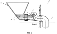
- FIG 1 illustrates a schematic of a toilet system 100, in accordance with the concepts of the present disclosure.
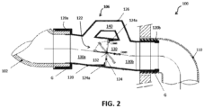
- Figure 2 shows an enlarged view of a portion of the toilet system 100, clearly showing the trapway arrangement in accordance with the concepts of the present disclosure.
- Figure 3 shows a schematic of the toilet system 100, in accordance with the concepts of the present disclosure.
- Figures 1 , 2 , and 3 should be referred to in conjunction with each other hereinafter, in order to clearly understand the concepts of the present disclosure.
- the toilet system 100 comprises of a water closet 102, a flushing arrangement 104, and a trapway arrangement 106.
- the toilet bowl 102 is a water closet adapted to receive faecal matter 108, as a user performs defaecation thereon.
- the toilet bowl 102 is described to be a wall mounted toilet bowl, it may be obvious to a person skilled in the art that the toilet bowl 102 may be a floor mounted toilet bowl as well.
- the toilet bowl 102 is in fluid communication with a drain line 110 via the trapway arrangement 106, for enabling evacuation of contents (faecal matter 108 + water) in the toilet bowl 102 to the drain line 110.
- the toilet bowl 102 is maintained with a sump water 112 therein with use of the trapway arrangement 106, which prevents sticking of faecal matter 108 in the toilet bowl 102 as well as prevent the leakage of foul gases from the drain line 110 into the toilet area.
- a structure and arrangement of the flush arrangement 104 and the trapway arrangement 106 will be described in detail in the forthcoming disclosure.
- the flush arrangement 104 is provided to flush faecal matter 108 from the toilet bowl 102, when required.
- the flush arrangement 104 includes a flush tank 114 and a flush valve 116.
- the flush tank 114 is a sealed pressurised tank fluidly connected to the toilet bowl 102, by way of the flush valve 116.
- the flush tank 114 stores flushing water that may be flushed to the toilet bowl 102, upon actuation of the flush valve 116.
- the flush valve 116 is further incorporated within the flush tank 114, and is adapted to allow/ restrict a supply of water from the flush tank 114 to the toilet bowl 102.
- the flush valve 116 allows the flow of water from the flush tank 114 to the toilet bowl 102 and perform the flushing action. Additionally, upon release/ deactivation, the flush valve 116 restricts the flow of water from the flush tank 114 to the toilet bowl 102.
- the flush arrangement 104 can be provided with a flush button 118, wherein upon pressing the flush button 118, the flush valve 116 is actuated to allow the flow of water from the flush tank 114 to the toilet bowl 102 and perform the flushing action. Moreover, in such embodiments, upon release of the flush button 118, the flush valve 116 is released to restrict the flow of water from the flush tank 114 to the toilet bowl 102.
- An actuation mechanism/ system 128 for actuation/ release of the flush valve 116 upon pressing/ release of the flush button 118 will be discussed later in details.
- the trapway arrangement 106 selectively fluidly connects the toilet bowl 102 to the drain line 110, to allow/restrict the flow of contents (faecal matter 108 + water) in the toilet bowl 102 to the drain line 110.
- the trapway arrangement 106 includes a horizontally positioned trapway member 120, a valve mechanism 122 including a valve member 124, an auxiliary flow member 126, and an actuation system 128.
- the valve member 124 is capable of being adjusted between a closed configuration and an open configuration. In the closed configuration, the valve member 124 restricts the flow of contents (faecal matter 108 + water) in the toilet bowl 102 to the drain line 110. In the open configuration, the valve member 124 allows the flow of contents (faecal matter 108 + water) in the toilet bowl 102 to the drain line 110.
- a structure and arrangement of various components of the trapway arrangement 106 will now be discussed in detail hereinafter.
- the trapway member 120 is an elongated tube made up of polymer material, and including a first end 120a and a second end 120b.
- the first end 120a of the trapway member 120 is connected to a lower portion of the toilet bowl 102, and the second end 120b of the trapway member 120 is connected to the drain line 110.
- the first end 120a and the second end 120b of the trapway member 120 are connected to the toilet bowl 102 and the drain line 110 respectively, by way of gaskets G.
- the trapway member 120 defines a main fluid passage 130 within an internal periphery.
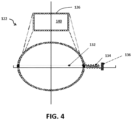
- Figure 4 shows a schematic of the valve mechanism 122 of the trapway arrangement 106, in accordance with the concepts of the present disclosure.
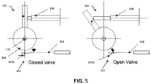
- Figure 5 shows an enlarged side view of a portion of the valve mechanism 122, illustrating the valve mechanism 122 in a closed position and an open position of the valve member 124, in accordance with the concepts of the present disclosure.
- Figure 1-5 should be referred to in conjunction with each other hereinafter, in order to clearly understand the concepts of the present disclosure.
- the valve mechanism 122 includes the valve member 124, a valve shaft 132, a torsional spring 134, and a valve actuation disc 136.
- the valve member 124 is a disc-plate type butterfly valve positioned within the main fluid passage 130 of the trapway member 120, thereby bisecting the main fluid passage 130 into two regions.
- the main fluid passage 130 includes a first flow region 130a defined on one side of the valve member 124 and fluidly connected to the toilet bowl 102, and a second flow region 130b defined on other side of the valve member 124 and fluidly connected to the drain line 110.
- the valve member 124 is mounted on the valve shaft 132.
- the valve shaft 132 is further rotatably supported on the trapway member 120 at opposite ends, such that the valve member 124 is disposed within the main fluid passage 130 of the trapway member 120.
- the torsional spring 134 is also attached to the valve shaft 132, such that an outer periphery of the valve member 124 normally seals with an inner periphery of the trapway member 120.
- a position of the valve member 124 is termed as a 'closed configuration'.
- the outer periphery of the valve member 124 is separated from the inner periphery of the trapway member 120.
- Such a position of the valve member 124 is termed as an ⁇ open configuration'.
- a rotational motion of the valve member beyond a certain point is further restricted by a valve stoppers 124a.
- the valve member 124 is capable of being adjusted between the closed configuration and the open configuration.
- the outer periphery of the valve member 124 normally seals with the inner periphery of the trapway member 120, and thus restricts the flow of contents (faecal matter 108 + water) in the toilet bowl 102 to the drain line 110.
- the open configuration the outer periphery of the valve member 124 is separated from the inner periphery of the trapway member 120, and thus allows the flow of contents (faecal matter 108 + water) in the toilet bowl 102 to the drain line 110.
- valve shaft 132 also supports the valve actuation disc 136 that facilitates adjustment of the valve member 124 between the open configuration and the closed configuration.
- valve member 124 is normally maintained in the closed configuration.
- a rotation of the valve actuation disc 136 corresponds to a rotation of the valve shaft 132, which further corresponds to adjustment of the valve member 124 from the closed configuration to the open configuration.
- a damper 138 is also connected to the valve actuation disc 136, to dampen the rotational motion of the valve actuation disc 136, the rotational motion of the valve shaft 134, and the rotational motion of the valve member 124.
- the actuation system 128 for adjusting the valve member 124 from the closed configuration to the open configuration will be discussed later in details.
- the auxiliary flow member 126 is provided to maintain a defined level of sump water 112 in the toilet bowl 102.
- the auxiliary flow member 126 maintains a seal of sump water 112 in the toilet bowl 102, such that a fowl smell from the drain line 110 is prevented to enter toilet area.
- the auxiliary flow member 126 is installed on top of the trapway member 120 fluidly connecting the first flow region 130a and the second flow region 130b of the main fluid passage 130.
- the auxiliary flow member 126 is made up of a continuous pipe structure suitably bent at angles, to be mounted on top of the trapway member 120.
- the auxiliary flow member 126 member further defines a first auxiliary fluid passage 140, to allow an overflow of the sump water 112 above the defined level, to flow from the toilet bowl 102 to the drain line 110 through the auxiliary fluid passage 140.
- the auxiliary fluid passage 140 allows the overflow of sump water to flow from the toilet bowl 102 to the first flow region 130a, through the auxiliary fluid passage 140, to the second flow region 130b and thus to the drain line 110.
- a defined level of sump water 112 maintained in the toiler bowl 102 is dependent on a height of the auxiliary flow member 126 relative to the trapway member 120.
- the defined level of sump water 112 can be adjusted by adjusting the height of the auxiliary flow member 126 relative to the trapway member 120.
- the auxiliary flow member 126 can be suitably structured and arranged to be capable of being adjusted in a plurality of heights relative to the trapway member 120, and thus the defined level of the sump water 112 maintained by the auxiliary flow member 126 is adjustable between a plurality of levels.
- Figure 6 shows a schematic of the trapway arrangement 106, employing such an embodiment of the auxiliary flow member 126, in accordance with the concepts of the present disclosure.
- Figure 7 shows a schematic of the toilet bowl 102, clearly showing a plurality of levels of the sump water 112 capable of being adjusted by such embodiment of the auxiliary flow member 126, in accordance with the concepts of the present disclosure.
- the auxiliary flow member 126 includes a first side arrangement 142, a second side arrangement 144, and an intermediate flexible member 146.
- Each of the first side arrangement 142 and the second side arrangement 144 are made up of multiple flow members.
- each of the first side arrangement 142 and the second side arrangement 144 are made up of two flow members 142a, 142b and 144a, 144b.
- the flow members 142a, 142b are interconnected with each other, to form the first side arrangement 142, while the flow members 144a, 144b are interconnected with each other, to form the second side arrangement 144.
- the intermediate flexible member 146 is connected to each of the first side arrangement 142 and the second side arrangement 144, to form the auxiliary flow member 126.
- the auxiliary flow member 126 In order to install the auxiliary flow member 126 on top of the trapway member 120, one of the flow members 142a and 144a of the first side arrangement 142 and the second side arrangement 144, respectively are installed on the trapway member 120, to be fluidly connected to the first flow region 130a and the second flow region 130b, respectively.
- the auxiliary flow member 126 is capable of maintaining a defined level of sump water 112 in the toilet bowl 102.
- one or more of the flow members 142a and 144a of the first side arrangement 142 and the second side arrangement 144 can be installed or uninstalled therefrom, to adjust the height of the auxiliary flow member 126 in the plurality of heights relative to the trapway member 120, and thus adjust the defined level of the sump water between the plurality of levels 148.
- each of the flush valve 116 of the flush arrangement 104 and the valve member 124 of the valve mechanism 122 of the trapway arrangement 106 are required to be substantially concurrently actuated. Therefore, in a preferred embodiment as described in the forthcoming disclosure, the valve member 124 of the valve mechanism 122 of the trapway arrangement 106 is required to be actuated concurrent to actuation of the flush valve 116 of the flush arrangement 104.
- valve member 124 will be explained hereinafter as being actuated concurrent to actuation of the flush valve 116, however, an embodiment with different timing of actuation of the valve member 124 and the flush valve 116, is also within a scope of the present disclosure. Furthermore, since in the preferred embodiment, the valve member 124 is required to be actuated concurrent to actuation of the valve member 124, the actuation system 128 may be utilized to actuate each of the flush valve 116 and the valve member 124.
- the present disclosure describes the actuation system 128 for concurrent actuation of each of the flush valve 116 and the valve member 124, it may be obvious to a person ordinarily skilled in the art that the flush valve 116 and the valve member 124, may also be actuated by concurrent operation of separate actuation systems for each of the flush valve 116 and the valve member 124.
- Actuation of the flush valve 116 refers to switching the flush valve 116 from a 'water storage state' to a 'water dispensing state'.
- Actuation of the valve member 124 refers to switching of the valve member 124 from the closed configuration to the open configuration.
- the actuation system 128 as disclosed in the present disclosure is employed to actuate each of the flush valve 116 and the valve member 124.
- actuation system 128 is a manual actuation system 128 that concurrently actuates each of the flush valve 116 and the valve member 124.
- actuation system 128 may also be contemplated, such as but not limited to, a foot pedal operated actuation system 128, a pneumatic actuation system 128, an electro mechanical actuation system 128.
- the manual actuation system 128 includes a flush valve actuation mechanism 150, a trapway valve actuation mechanism 152, and a clutch wire 154 connecting the flush valve actuation mechanism 150 and the trapway valve actuation mechanism 152.
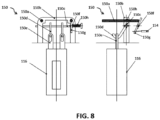
- Figure 8 shows a front view and a side view of the flush valve actuation mechanism 150 of the manual actuation system 128.
- Figures 5 shows the trapway valve actuation mechanism 152 of the manual actuation system 128.
- the flush valve actuation mechanism 150 includes an actuation rod 150a, an actuation bracket 150b, a rotating shaft 150c, a link rod 150d, a flush valve link 150e, a clutch wire actuator shaft 150f, a clutch wire actuator lever 150g, and a coil spring 150h.
- One end of the clutch wire 154 is connected to the clutch wire actuator lever 150g.
- the actuation rod 150a, an actuation bracket 150b, a rotating shaft 150c, a link rod 150d, a flush valve link 150e, a clutch wire actuator shaft 150f, a clutch wire actuator lever 150g, and a coil spring 150h are connected with each other and with the flush valve 116, such that upon pressing the flush button 118, the flush valve 116 is actuated.
- the clutch wire 154 Concurrent to actuation of the flush valve 116, the clutch wire 154 is also pulled upon pressing of the flush button 118. Further, the trapway valve actuation mechanism 152 includes a wire clip 152a connecting other end of the clutch wire 154 to the valve actuation disc 136 of the valve mechanism 122, such that upon pulling the clutch wire 154, the valve member 124 is switched from the closed configuration to the open configuration.
- the flush valve actuation mechanism 150 actuates the flush valve 116 and concurrently pulls the clutch wire 154, which corresponds to the trapway valve actuation mechanism 152 actuating the valve member 124 to be switched from the closed configuration to the open configuration. Therefore, by pressing the flush button 118, the flush valve 116 and the valve member 124 are concurrently actuate.
- the flush valve 116 is actuated, it allows the supply of water to the toilet bowl 102.
- the valve member 124 of the trapway arrangement 106 is actuated, it allows the contents (faceal matter 108 + water) in the toilet bowl 102 to be flown to the drain line 110 through the main fluid passage 130.
- each of the flush valve 116 and the valve member 124 are deactivated.
- Deactivation of the flush valve 116 refers to switching back of the flush valve 116 from the 'water dispensing state' to the 'water storage state'.
- Deactivation of the valve member 124 refers to switching of the valve member 124 from the open configuration to the closed configuration. Accordingly, as the flush valve 116 is deactivated upon release of the flush button 118, the supply of water to the toilet bowl 102 is restricted. Moreover, as the valve member 124 is deactivated, the flow of contents from the toilet bowl 102 to the drain line 110 is restricted.
- the flush valve 116 is suitably structured, such that a timing of deactivation of the flush valve 116 is more than a timing of deactivation of the valve member 124. Accordingly, upon flushing of the contents (faceal matter 108 + water) in the toilet bowl 102 to the drain line 110, firstly the valve member 124 is deactivated while the flush valve 116 is still activated. Therefore, the flush valve 116 fills the toilet bowl 102 with fresh sump water 112 that is not flown to the drain line 110. Thereafter, the flush valve 116 is deactivated to restrict the supply of water to the toilet bowl 102. Thus, an operation of the flush valve 116 and the valve member 124, to perform flushing operation is completed.
- Figure 9a shows a side view of the trapway arrangement 106, showing the embodiment of the foot pedal operated actuation system 128, in accordance with the concept of the present disclosure.
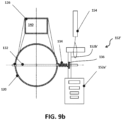
- Figure 9b shows a schematic of a valve mechanism 122 of the trapway arrangement 106, showing the embodiment of the foot pedal operated actuation system 128, in accordance with the concepts of the present disclosure.
- Figure, 5 , 9a , and 9b should be referred to in conjunction with each other, in order to clearly understand concepts of the embodiment of the foot-pedal operated actuation system 128, in accordance with the concepts of the present disclosure.
- the foot pedal actuation system 128 includes a flush valve actuation mechanism 150', a trapway valve actuation mechanism 152', and a clutch wire 154 connecting the flush valve actuation mechanism 150 and the trapway valve actuation mechanism 152'. It may be noted that the flush valve actuation mechanism 150' and the clutch wire 154 of the foot pedal operated actuation system 128, is same as the flush valve actuation mechanism 150 and the clutch wire 154 of the manual actuation system 128. Therefore, the flush valve actuation mechanism 150' and the clutch wire 154 of the foot pedal operated actuation system 128 is not described, for the sake or brevity.
- the trapway valve actuation mechanism 152' of the foot pedal operated actuation system 128 includes a foot pedal 152a' and a foot lever 152b'.
- the foot pedal is connected to the foot lever 152b', which in turn is connected to the valve actuation disc 136 of the valve mechanism 122.
- the foot lever 152b' is also connected to one end of the clutch wire 154, while other end of the clutch wire is connected to the clutch wire actuator lever 150g of the flush valve actuation mechanism 150.
- the clutch wire 154 Concurrent to actuation of the valve member 124, upon of the foot pedal 152a' by user's feet 156, the clutch wire 154 is pulled. Accordingly, upon pulling the clutch wire 154, the flush valve actuation mechanism 150 concurrently actuates the flush valve 116.
- the trapway valve actuation mechanism 152' actuates the valve member 124, and concurrently pulls the clutch wire 154, which corresponds to the clutch wire 154 causing the flush valve actuation mechanism 150 to actuate the flush valve 116. Therefore, by pressing the foot pedal 152a', the flush valve 116 and the valve member 124 are concurrently actuated. As the flush valve 116 is actuated, it allows the supply of water to the toilet bowl 102.
- valve member 124 of the trapway arrangement 106 As the valve member 124 of the trapway arrangement 106 is actuated, it allows the contents (faceal matter 108 + water) in the toilet bowl 102 to be flown to the drain line 110 through the main fluid passage 130. Thus, flushing is efficiently performed. Furthermore, upon release of the foot pedal 152a', each of the flush valve 116 and the valve member 124 are deactivated. Deactivation of the flush valve 116 refers to switching back of the flush valve 116 from the 'water dispensing state' to the 'water storage state'. Deactivation of the valve member 124 refers to switching of the valve member 124 from the open configuration to the closed configuration.
- the flush valve 116 is deactivated upon release of the foot pedal 152a', the supply of water to the toilet bowl 102 is restricted. Moreover, as the valve member 124 is deactivated, the flow of contents from the toilet bowl 102 to the drain line 110 is restricted. It may be noted that the flush valve 116 is suitably structured, such that a timing of deactivation of the flush valve 116 is more than a timing of deactivation of the valve member 124. Accordingly, upon flushing of the contents (faceal matter 108 + water) in the toilet bowl 102 to the drain line 110, firstly the valve member 124 is deactivated while the flush valve 116 is still activated.
- the flush valve 116 fills the toilet bowl 102 with fresh sump water 112 that is not flown to the drain line 110. Thereafter, the flush valve 116 is deactivated to restrict the supply of water to the toilet bowl 102. Thus, an operation of the flush valve 116 and the valve member 124, to perform flushing operation is completed.
- FIG. 10a and 10b there is shown various portions of the embodiment of the pneumatic actuation system 128.
- the pneumatic actuation system 128 includes a flush valve actuation mechanism 150", a trapway valve actuation mechanism 152", and a connecting fluid line 158 fluidly interconnecting the flush valve actuation mechanism 150" and the trapway valve actuation mechanism 152".
- Figure 10a shows a front view flush valve actuation mechanism 150" of the embodiment of the pneumatic actuation system 128, and enlarged views of portions of the flush valve actuation mechanism 150" in the actuated state and the deactivate state of the flush valve 116, in accordance with the concepts of the present disclosure.
- Figure 10b shows an enlarged side view of a portion of the valve mechanism 122, illustrating a positioning of various components of the valve mechanism 122 and the trapway valve actuation mechanism 152" of the embodiment of the pneumatic actuation system 128 in a closed position and an open position of the valve member 124, in accordance with the concepts of the present disclosure.
- Figures 10a and 10b should be referred to in conjunction with each other, in order to clearly understand concepts of the embodiment of the pneumatic actuation system 128, in accordance with the concepts of the present disclosure.
- the flush valve actuation mechanism 150" includes a primary air bellow 150a", an air distributor 150b", a couple of secondary air bellows 150c", a link rod 150d", and valve links 150e".
- the primary air bellow 150a”, the air distributor 150b", the secondary air bellows 150c", the link rod 150d", and the valve links 150e are suitably arranged with each other, such that upon pressing of the flush button 118 the flush valve 116 is actuated and a first air flow is generated to the connecting fluid line 158.
- the primary air bellow 150a" generates an airflow to the air distributor 150b", which distributes the airflow between a first airflow directed towards the connecting fluid line 158 and a second airflow directed towards the secondary air bellows 150c" through the supply line 160.
- the secondary air bellows 150c" in conjunction with a link rod 150d", and valve links 150e", actuates the flush valve 116.
- the flush valve actuation mechanism 150" actuates the flush valve 116 and concurrently generates the first airflow in the connecting fluid line 158.
- the trapway valve actuation mechanism 152" of the pneumatic actuation system 128 includes a main air bellow 152a", and a secondary clutch wire 152b" connected thereto.
- the main air bellow 152a" is fluidly connected to the connecting fluid line 158, to receive the first airflow.
- the secondary clutch wire 152b" is further connected to the valve actuation disc 136 of the valve mechanism 122.
- the flush valve actuation mechanism 150 actuates the flush valve 116 and concurrently generated the first airflow in the connecting fluid line 158, which corresponds to the first airflow causing the trapway valve actuation mechanism 152" to actuate the valve member 124 to be switched from the closed configuration to the open configuration. Therefore, by pressing the flush button 118, the flush valve 116 and the valve member 124 are concurrently actuated. As the flush valve 116 is actuated, it allows the supply of water to the toilet bowl 102.
- valve member 124 of the trapway arrangement 106 As the valve member 124 of the trapway arrangement 106 is actuated, it allows the contents (faceal matter 108 + water) in the toilet bowl 102 to be flown to the drain line 110 through the main fluid passage 130. Thus, flushing is efficiently performed. Furthermore, upon release of the flush button 118, each of the flush valve 116 and the valve member 124 are deactivated. Deactivation of the flush valve 116 refers to switching back of the flush valve 116 from the 'water dispensing state' to the 'water storage state'. Deactivation of the valve member 124 refers to switching of the valve member 124 from the open configuration to the closed configuration. Accordingly, as the flush valve 116 is deactivated upon release of the flush button 118, the supply of water to the toilet bowl 102 is restricted.
- the flush valve 116 is suitably structured, such that a timing of deactivation of the flush valve 116 is more than a timing of deactivation of the valve member 124. Accordingly, upon flushing of the contents (faceal matter 108 + water) in the toilet bowl 102 to the drain line 110, firstly the valve member 124 is deactivated while the flush valve 116 is still activated. Therefore, the flush valve 116 fills the toilet bowl 102 with fresh sump water 112 that is not flown to the drain line 110. Thereafter, the flush valve 116 is deactivated to restrict the supply of water to the toilet bowl 102. Thus, an operation of the flush valve 116 and the valve member 124, to perform flushing operation is completed.
- FIGs. 11a-11c there is shown various portions of the embodiment of the electro-mechanical actuation system 128.
- the electro-mechanical actuation system 128 includes an IR sensor 162, a flush valve actuation mechanism 150′′′, a trapway valve actuation mechanism 152′′′, and a control unit 164.
- Figure 11a shows a block diagram of the embodiment of the electro-mechanical actuation system 128, in accordance with the concepts of the present disclosure.
- Figure 11b shows the trapway valve actuation mechanism 152′′′ of the embodiment of the electro-mechanical actuation system 128, in accordance with the concepts of the present disclosure.
- Figure 11c shows an enlarged side view of a portion of the valve mechanism 122, illustrating a positioning of various components of the valve mechanism 122 and the trapway valve actuation mechanism 152′′′ of the embodiment of the pneumatic actuation system 128 in a closed position and an open position of the valve member 124, in accordance with the concepts of the present disclosure.
- Figures 11a , 11b , and 11c should be referred to in conjunction with each other, in order to clearly understand concepts of the embodiment of the electro-mechanical actuation system 128, in accordance with the concepts of the present disclosure.
- the IR sensor 162 transmits the actuation signal to the control unit 164.
- the control unit 164 then controls each of the flush valve actuation mechanism 150′′′ and the trapway valve actuation mechanism 152′′′, to concurrently actuate the flush valve 116 and the valve member 124.
- the flush valve actuation mechanism 150′′′ includes a flush valve solenoid 150a'", a connector wire 150b'", a link rod 150c''', a pair of flush valve links 150d'", an actuation bracket, 150e'".
- the flush valve solenoid 150a′′′ is electrically connected to the control unit 164 to receive the actuation signal therefrom.
- flush valve solenoid 150a' the connector wire 150b'
- the link rod 150c''' the link rod 150c'''
- the pair of flush valve links 150d' and the actuation bracket, 150e'
- the control unit also sends the actuation signal to the trapway valve actuation mechanism 152'".
- the trapway valve actuation mechanism 152′′′ includes a trapway valve solenoid 152a′′′ and a wire 152b'".
- the wire 152b′′′ is connected to the trapway valve solenoid 152a′′′ at one end and is connected to the valve actuation disc 136 of the valve mechanism 122 at the other end. Further, the trapway valve solenoid 152a′′′ is electrically connected to the control unit 164 to receive the actuation signal therefrom. With such arrangement, upon receipt of the actuation signal by the trapway valve solenoid 152a'", the trapway valve 124 is actuated from the closed position to the open position.
- the IR sensor 162 sends signal to the control unit 164.
- the control unit further sends actuation signals to each of the flush valve solenoid 150a′′′ of the flush valve actuation mechanism 150′′′ and the trapway valve solenoid 152a′′′ of the trapway valve actuation mechanism 152'", for concurrent actuation of the flush valve 116 and the trapway member 124.
- the flush valve 116 is actuated, it allows the supply of water to the toilet bowl 102.
- valve member 124 of the trapway arrangement 106 As the valve member 124 of the trapway arrangement 106 is actuated, it allows the contents (faceal matter 108 + water) in the toilet bowl 102 to be flown to the drain line 110 through the main fluid passage 130. Thus, flushing is efficiently performed. Furthermore, upon completion of flushing operations, the control unit 164 sends deactivation signals to each of the flush valve solenoid 150a′′′ of the flush valve actuation mechanism 150′′′ and the trapway valve solenoid 152a′′′ of the trapway valve actuation mechanism 152'", for deactivation of the flush valve 116 and the valve member 124 respectively. Deactivation of the flush valve 116 refers to switching back of the flush valve 116 from the 'water dispensing state' to the 'water storage state'.
- Deactivation of the valve member 124 refers to switching of the valve member 124 from the open configuration to the closed configuration. Accordingly, as the flush valve 116 is deactivated upon receipt of the deactivation signal from the control unit 164, the supply of water to the toilet bowl 102 is restricted. Moreover, as the valve member 124 is deactivated, the flow of contents from the toilet bowl 102 to the drain line 110 is restricted. It may be noted that the control unit 164 send deactivation signal to the flush valve solenoid 150a′′′ of the flush valve actuation mechanism 150′′′ later than the deactivation signal to the trapway valve solenoid 152a′′′ of the trapway valve actuation mechanism 152'".
- the valve member 124 is deactivated while the flush valve 116 is still activated. Therefore, the flush valve 116 fills the toilet bowl 102 with fresh sump water 112 that is not flown to the drain line 110. Thereafter, the control unit 164 deactivates the flush valve 116, to restrict the supply of water to the toilet bowl 102. Thus, an operation of the flush valve 116 and the valve member 124, to perform flushing operation is completed.
- the present invention takes into account a number of advantages.
- One such advantage is during emergency operating conditions, such as cleaning of the toilet bowl 102.
- the trapway arrangement 106 is required to be manually overridden.
- the trapway arrangement 106 is required to allow the overflow of water from the toilet bowl 102 to the drain line 110, without initiating the flushing operations and/or actuating the valve member 124.
- the auxiliary member 126 allows the overflow of water above the defined level of the sump water 112 to flow form the toilet bowl 102 to the drain line 110 through the auxiliary fluid passage 140.
- the trapway arrangement 106 discloses usage of a flat/horizontal trapway member 120 for connecting the toilet bowl 102 to the drain line 110. Therefore, a need of complex inverted U channel is avoided.
- usage of the flat/ horizontal trapway requires minimal water requirement for flushing of faecal matter 108 from the toilet bowl 102.
- the overall water consumption by the toilet bowl 102 of the toilet system 100 is reduced optimally. This results in an increase in the functional efficiency of the toilet bowl 102 of the toilet system 100. This provides for the toilet arrangement with more eco-friendly nature, more functional efficiency, and less bulky.
- the trapway arrangement 106 discloses usage of a flat/horizontal trapway member 120 for connecting the toilet bowl 102 to the drain line 110. Specifically, a need of complex inverted U channel is avoided. Thus, usage of the flat/ horizontal trapway 120 requires low water head, and thus the flush tank 114 can be placed at relatively reduced heights. Thus, reducing the vertical space requirement of the toilet system 100.
- the disclosed trapway arrangement 106 discloses usage of a flat/horizontal trapway 120 for connecting the toilet bowl 102 to the drain line 110.
- the structure and arrangement of the toilet bowl 102 is less complex. Therefore, manufacturing of the toilet bowl 102 of the toilet system 100, such as but not limited to ceramic manufacturing process, is relatively easy and less cumbersome. Particularly, manufacturing process of such toilet bowl 102, requires employment of less complex moulds and is thus relatively easy.
- Yet another advantage of the present invention relates to adaptability of the toilet system 100 disclosed in the present disclosure with change in geography.
- the auxiliary member 126 of the trapway arrangement 106 of the present disclosure is capable of adjusting defined levels of the sump water 112 capable of being carried by the toilet bowl 102, there is no need for manufacturing different toilet bowls 102 for different countries according to their sump water level requirements. This avoids management issues and substantially reduces management costs.
Landscapes
- Engineering & Computer Science (AREA)
- Health & Medical Sciences (AREA)
- Life Sciences & Earth Sciences (AREA)
- Hydrology & Water Resources (AREA)
- Public Health (AREA)
- Water Supply & Treatment (AREA)
- Aviation & Aerospace Engineering (AREA)
- Sanitary Device For Flush Toilet (AREA)
Description
- The present disclosure generally relates to sanitary systems, such as toilet systems. More particularly, the present disclosure relates to a substantially horizontal trapway arrangement for a toilet system, for allowing/restricting the flow of contents of the toilet bowl to the drain line.
-
DE 6 881 C discloses a water closet with double odor trap, and regular flushing after each use, which is automatically actuated by the opening and closing of the flap, assembled and constructed in its parts. -
GB 2 430 993 A -
SU 1 536152 A -
FR 660 940 A -
FR 450174 A -
US 5 238 220 A discloses a butterfly valve utilized to control air flow in the environmental control air distribution system of an aircraft. A linkage system enables the valve to be manually controlled under normal conditions but to be shut off remotely in case of an emergency condition. - Toilet systems are known in sanitation industry, to enable persons to defecate in good sanitary conditions. A typical toilet system includes a toilet bowl (also referred to as a water closet) and a flush arrangement. The water closet is provided to receive faecal matter, when a user performs defecation thereon. The flush arrangement is provided to supply water to the water closet, for removing faecal matter therefrom by pushing the faecal matter to a drain line with use of water pressure.
- Water consumption optimization by a toilet system is also an essential requirement in addition to flushing. Typically, the toilet system requires not only more water, but also higher water head, to flush the faecal matter. The faecal matter is flushed to a drain line. The higher water head, here, relates to the potential energy of the water in the water storage tank of the flush arrangement. For such high water-head requirements, the water storage tank of the flush arrangement is required to be positioned at greater heights relative to the water closet. Such undesirable water consumption and higher water head requirements makes the toilet system less eco-friendly, functionally inefficient, and bulkier.
- The water closet of the toilet system includes an integrally formed trapway, which fluidly connects the water closet to a drain line. The trapway allows for exit of contents (water and/or faecal matter) received in the water closet to the drain line. Moreover, the trapway also maintains a water seal of sump water in the toilet bowl, to avoid fowl smell. Conventionally, the trapway is an inverted U-shaped channel including at least one vertical channel, to maintain the water seal of sump water in the water closet. While flushing, the contents (water and/or faecal matter) in the toilet bowl have to climb the vertical channel of the trapway. This requires more flushing volume (more water) for flushing operations, which may be less eco-friendly. Additionally, such requirement of climbing the vertical channel requires a higher water head, which require the flush tank to be positioned at relatively higher heights. This may result in poor space-utilization. Such undesirable water consumption and higher water head requirements makes the toilet system less eco-friendly, functionally inefficient, and bulkier. Moreover, such water closets with integrated complex structure of trapways is difficult to manufacture and require complex and expensive moulds for such manufacturing in an industrial set-up.
- In addition to the aforementioned problems, various countries/ regions define various regulations of construction for the toilet bowl. For example, different countries/ regions define different levels of sump water requirements to be maintained in the toilet bowl, for better sanitation in that particular region. Therefore, the toilet bowls are required to be manufactured differently for different regions, for enabling different levels of sump water for different countries/ regions. This requires a lot of management issues. For example, a toilet bowl manufactured for one region/ country may not be supplied/ delivered to another region/ country, due to difference in sump water level requirements in the two countries/ regions. This incurs substantially high management costs.
- For example, a Korean patent application number
KR101789012 B1 - Accordingly, in light of the aforementioned drawbacks and several other inherent in the existing arts, it is an object underlining the present invention to provide a trapway arrangement adapted for a toilet system, which provides for, less wastage of water, increased overall functional efficiency, minimal space requirements, and relatively easy manufacturing.
- The solution of this object is achieved by the features of claim 1. The dependent claims contain advantageous embodiments of the present invention
- The present invention, both as to its organization and manner of operation, together with further objects and advantages, may best be understood by reference to the following description, taken in connection with the accompanying drawings. These and other details of the present invention will be described in connection with the accompanying drawings, which are furnished only by way of illustration and not in limitation of the invention, and in which drawings:
-
Figure 1 illustrates a schematic of a toilet system, illustrating a trapway arrangement, in accordance with the concepts of the present disclosure. -
Figure 2 shows an enlarged view of a portion of the toilet system, clearly illustrating the trapway arrangement ofFigure 1 , in accordance with the concepts of the present disclosure. -
Figure 3 shows a perspective of the toilet system, illustrating a front view and a side view of the toilet system, in accordance with the concepts of the present disclosure. -
Figure 4 shows a schematic of a valve mechanism of the trapway arrangement ofFigure 1 , in accordance with the concepts of the present disclosure. -
Figure 5 shows an enlarged side view of a portion of the valve mechanism, illustrating the valve mechanism in a closed position and an open position of the valve member, in accordance with the concepts of the present disclosure. -
Figure 6 shows a schematic of the trapway arrangement, employing such another embodiment of the auxiliary flow member, in accordance with the concepts of the present disclosure. -
Figure 7 shows a schematic of the toilet bowl, clearly showing a plurality of levels of the sump water capable of being adjusted by another embodiment of the auxiliary flow member, in accordance with the concepts of the present disclosure. -
Figure 8 shows a front view and a side view of a flush valve actuation mechanism of an actuation system, in accordance with the concepts of the present disclosure. -
Figure 9a shows a side view of the trapway arrangement, showing the embodiment of the foot pedal operated actuation system, in accordance with the concept of the present disclosure. -
Figure 9b shows a schematic of a valve mechanism of the trapway arrangement, showing the embodiment of the foot pedal operated actuation system, in accordance with the concepts of the present disclosure. -
Figure 10a shows a front view flush valve actuation mechanism of the embodiment of the pneumatic actuation system, and enlarged views of portions of the flush valve actuation mechanism in the actuated state and the deactivated state of the flush valve, in accordance with the concepts of the present disclosure. -
Figure 10b shows an enlarged side view of a portion of the valve mechanism, illustrating a positioning of various components of the valve mechanism and the trapway valve actuation mechanism of the embodiment of the pneumatic actuation system in a closed position and an open position of the valve member, in accordance with the concepts of the present disclosure. -
Figure 11a shows a block diagram of the embodiment of the electro-mechanical actuation system, in accordance with the concepts of the present disclosure. -
Figure 11b shows the trapway valve actuation mechanism of the embodiment of the electro-mechanical actuation system, in accordance with the concepts of the present disclosure. -
Figure 11c shows an enlarged side view of a portion of the valve mechanism, illustrating a positioning of various components of the valve mechanism and the trapway valve actuation mechanism of the embodiment of the pneumatic actuation system in a closed position and an open position of the valve member, in accordance with the concepts of the present disclosure. - In the following description, for the purposes of explanation, various specific details are set forth in order to provide a thorough understanding of embodiments of the present invention. Example embodiments of the present invention are described below, as illustrated in various drawings in which like reference numerals refer to the same parts throughout the different drawings.
-
Figure 1 illustrates a schematic of atoilet system 100, in accordance with the concepts of the present disclosure.Figure 2 shows an enlarged view of a portion of thetoilet system 100, clearly showing the trapway arrangement in accordance with the concepts of the present disclosure.Figure 3 shows a schematic of thetoilet system 100, in accordance with the concepts of the present disclosure.Figures 1 ,2 , and3 , should be referred to in conjunction with each other hereinafter, in order to clearly understand the concepts of the present disclosure. Thetoilet system 100 comprises of awater closet 102, aflushing arrangement 104, and atrapway arrangement 106. - The
toilet bowl 102 is a water closet adapted to receivefaecal matter 108, as a user performs defaecation thereon. Although, thetoilet bowl 102 is described to be a wall mounted toilet bowl, it may be obvious to a person skilled in the art that thetoilet bowl 102 may be a floor mounted toilet bowl as well. Thetoilet bowl 102 is in fluid communication with adrain line 110 via thetrapway arrangement 106, for enabling evacuation of contents (faecal matter 108 + water) in thetoilet bowl 102 to thedrain line 110. Also, thetoilet bowl 102 is maintained with asump water 112 therein with use of thetrapway arrangement 106, which prevents sticking offaecal matter 108 in thetoilet bowl 102 as well as prevent the leakage of foul gases from thedrain line 110 into the toilet area. A structure and arrangement of theflush arrangement 104 and thetrapway arrangement 106 will be described in detail in the forthcoming disclosure. - The
flush arrangement 104 is provided to flushfaecal matter 108 from thetoilet bowl 102, when required. Theflush arrangement 104 includes aflush tank 114 and aflush valve 116. Theflush tank 114 is a sealed pressurised tank fluidly connected to thetoilet bowl 102, by way of theflush valve 116. In particular, theflush tank 114 stores flushing water that may be flushed to thetoilet bowl 102, upon actuation of theflush valve 116. Theflush valve 116 is further incorporated within theflush tank 114, and is adapted to allow/ restrict a supply of water from theflush tank 114 to thetoilet bowl 102. Particularly, upon actuation, theflush valve 116 allows the flow of water from theflush tank 114 to thetoilet bowl 102 and perform the flushing action. Additionally, upon release/ deactivation, theflush valve 116 restricts the flow of water from theflush tank 114 to thetoilet bowl 102. Theflush arrangement 104 can be provided with aflush button 118, wherein upon pressing theflush button 118, theflush valve 116 is actuated to allow the flow of water from theflush tank 114 to thetoilet bowl 102 and perform the flushing action. Moreover, in such embodiments, upon release of theflush button 118, theflush valve 116 is released to restrict the flow of water from theflush tank 114 to thetoilet bowl 102. An actuation mechanism/system 128 for actuation/ release of theflush valve 116 upon pressing/ release of theflush button 118 will be discussed later in details. - The
trapway arrangement 106 selectively fluidly connects thetoilet bowl 102 to thedrain line 110, to allow/restrict the flow of contents (faecal matter 108 + water) in thetoilet bowl 102 to thedrain line 110. Thetrapway arrangement 106 includes a horizontally positionedtrapway member 120, avalve mechanism 122 including avalve member 124, anauxiliary flow member 126, and anactuation system 128. Notably, thevalve member 124 is capable of being adjusted between a closed configuration and an open configuration. In the closed configuration, thevalve member 124 restricts the flow of contents (faecal matter 108 + water) in thetoilet bowl 102 to thedrain line 110. In the open configuration, thevalve member 124 allows the flow of contents (faecal matter 108 + water) in thetoilet bowl 102 to thedrain line 110. A structure and arrangement of various components of thetrapway arrangement 106 will now be discussed in detail hereinafter. - The
trapway member 120 is an elongated tube made up of polymer material, and including afirst end 120a and asecond end 120b. Thefirst end 120a of thetrapway member 120 is connected to a lower portion of thetoilet bowl 102, and thesecond end 120b of thetrapway member 120 is connected to thedrain line 110. Notably, thefirst end 120a and thesecond end 120b of thetrapway member 120 are connected to thetoilet bowl 102 and thedrain line 110 respectively, by way of gaskets G. Further, thetrapway member 120 defines amain fluid passage 130 within an internal periphery. -
Figure 4 shows a schematic of thevalve mechanism 122 of thetrapway arrangement 106, in accordance with the concepts of the present disclosure.Figure 5 shows an enlarged side view of a portion of thevalve mechanism 122, illustrating thevalve mechanism 122 in a closed position and an open position of thevalve member 124, in accordance with the concepts of the present disclosure.Figure 1-5 should be referred to in conjunction with each other hereinafter, in order to clearly understand the concepts of the present disclosure. Thevalve mechanism 122 includes thevalve member 124, avalve shaft 132, atorsional spring 134, and avalve actuation disc 136. - The
valve member 124 is a disc-plate type butterfly valve positioned within themain fluid passage 130 of thetrapway member 120, thereby bisecting themain fluid passage 130 into two regions. In particular, themain fluid passage 130 includes afirst flow region 130a defined on one side of thevalve member 124 and fluidly connected to thetoilet bowl 102, and asecond flow region 130b defined on other side of thevalve member 124 and fluidly connected to thedrain line 110. Furthermore, thevalve member 124 is mounted on thevalve shaft 132. Thevalve shaft 132 is further rotatably supported on thetrapway member 120 at opposite ends, such that thevalve member 124 is disposed within the
main fluid passage 130 of thetrapway member 120. Moreover, thetorsional spring 134 is also attached to thevalve shaft 132, such that an outer periphery of thevalve member 124 normally seals with an inner periphery of thetrapway member 120. Such a position of thevalve member 124 is termed as a 'closed configuration'. Moreover, upon rotation of thevalve shaft 132 against a spring force of thetorsional spring 134, the outer periphery of thevalve member 124 is separated from the inner periphery of thetrapway member 120. Such a position of thevalve member 124 is termed as an `open configuration'. Notably, a rotational motion of the valve member beyond a certain point is further restricted by avalve stoppers 124a. Accordingly, it may be said that thevalve member 124 is capable of being adjusted between the closed configuration and the open configuration. In the closed configuration, the outer periphery of thevalve member 124 normally seals with the inner periphery of thetrapway member 120, and thus restricts the flow of contents (faecal matter 108 + water) in thetoilet bowl 102 to thedrain line 110. In the open configuration, the outer periphery of thevalve member 124 is separated from the inner periphery of thetrapway member 120, and thus allows the flow of contents (faecal matter 108 + water) in thetoilet bowl 102 to thedrain line 110. Furthermore, it may be noted that thevalve shaft 132 also supports thevalve actuation disc 136 that facilitates adjustment of thevalve member 124 between the open configuration and the closed configuration. In particular, thevalve member 124 is normally maintained in the closed configuration. A rotation of thevalve actuation disc 136 corresponds to a rotation of thevalve shaft 132, which further corresponds to adjustment of thevalve member 124 from the closed configuration to the open configuration. Notably, adamper 138 is also connected to thevalve actuation disc 136, to dampen the rotational motion of thevalve actuation disc 136, the rotational motion of thevalve shaft 134, and the rotational motion of thevalve member 124. The
actuation system 128 for adjusting thevalve member 124 from the closed configuration to the open configuration will be discussed later in details. - Furthermore, the
auxiliary flow member 126 is provided to maintain a defined level ofsump water 112 in thetoilet bowl 102. In particular, theauxiliary flow member 126 maintains a seal ofsump water 112 in thetoilet bowl 102, such that a fowl smell from thedrain line 110 is prevented to enter toilet area. Theauxiliary flow member 126 is installed on top of thetrapway member 120 fluidly connecting thefirst flow region 130a and thesecond flow region 130b of themain fluid passage 130. In one embodiment, theauxiliary flow member 126 is made up of a continuous pipe structure suitably bent at angles, to be mounted on top of thetrapway member 120. Theauxiliary flow member 126 member further defines a firstauxiliary fluid passage 140, to allow an overflow of thesump water 112 above the defined level, to flow from thetoilet bowl 102 to thedrain line 110 through theauxiliary fluid passage 140. In particular, theauxiliary fluid passage 140 allows the overflow of sump water to flow from thetoilet bowl 102 to thefirst flow region 130a, through theauxiliary fluid passage 140, to thesecond flow region 130b and thus to thedrain line 110. Notably, a defined level ofsump water 112 maintained in thetoiler bowl 102 is dependent on a height of theauxiliary flow member 126 relative to thetrapway member 120. Moreover, the defined level ofsump water 112 can be adjusted by adjusting the height of theauxiliary flow member 126 relative to thetrapway member 120. - The
auxiliary flow member 126 can be suitably structured and arranged to be capable of being adjusted in a plurality of heights relative to thetrapway member 120, and thus the defined level of thesump water 112 maintained by theauxiliary flow member 126 is adjustable between a plurality of levels.Figure 6 shows a schematic of thetrapway arrangement 106, employing such an embodiment of theauxiliary flow member 126, in accordance with the concepts of the present disclosure.Figure 7 shows a schematic of thetoilet bowl 102, clearly showing a plurality of levels of thesump water 112 capable of being adjusted by such embodiment of theauxiliary flow member 126, in accordance with the concepts of the present disclosure.Figures 6 and7 should be referred to in conjunction with each other hereinafter, in order to clearly understand the concepts of the present disclosure. In such embodiments, theauxiliary flow member 126 includes afirst side arrangement 142, asecond side arrangement 144, and an intermediateflexible member 146. Each of thefirst side arrangement 142 and thesecond side arrangement 144 are made up of multiple flow members. For example, each of thefirst side arrangement 142 and thesecond side arrangement 144 are made up of twoflow members flow members first side arrangement 142, while theflow members second side arrangement 144. Further, the intermediateflexible member 146 is connected to each of thefirst side arrangement 142 and thesecond side arrangement 144, to form theauxiliary flow member 126. In order to install theauxiliary flow member 126 on top of thetrapway member 120, one of theflow members first side arrangement 142 and thesecond side arrangement 144, respectively are installed on thetrapway member 120, to be fluidly connected to thefirst flow region 130a and thesecond flow region 130b, respectively. With such arrangement, theauxiliary flow member 126 is capable of maintaining a defined level ofsump water 112 in thetoilet bowl 102. Moreover, one or more of theflow members first side arrangement 142 and thesecond side arrangement 144 can be installed or uninstalled therefrom, to adjust the height of the auxiliary flow
member 126 in the plurality of heights relative to thetrapway member 120, and thus adjust the defined level of the sump water between the plurality oflevels 148. - Furthermore, it may be obvious to a person ordinarily skilled in the art that in order to efficiently perform the flushing operations, i.e. for efficient removal of contents (
faecal matter 108 + water) in thetoilet bowl 102, each of theflush valve 116 of theflush arrangement 104 and thevalve member 124 of thevalve mechanism 122 of thetrapway arrangement 106 are required to be substantially concurrently actuated. Therefore, in a preferred embodiment as described in the forthcoming disclosure, thevalve member 124 of thevalve mechanism 122 of thetrapway arrangement 106 is required to be actuated concurrent to actuation of theflush valve 116 of theflush arrangement 104. Although, in the present disclosure, thevalve member 124 will be explained hereinafter as being actuated concurrent to actuation of theflush valve 116, however, an embodiment with different timing of actuation of thevalve member 124 and theflush valve 116, is also within a scope of the present disclosure. Furthermore, since in the preferred embodiment, thevalve member 124 is required to be actuated concurrent to actuation of thevalve member 124, theactuation system 128 may be utilized to actuate each of theflush valve 116 and thevalve member 124. Although, the present disclosure describes theactuation system 128 for concurrent actuation of each of theflush valve 116 and thevalve member 124, it may be obvious to a person ordinarily skilled in the art that theflush valve 116 and thevalve member 124, may also be actuated by concurrent operation of separate actuation systems for each of theflush valve 116 and thevalve member 124. Actuation of theflush valve 116 refers to switching theflush valve 116 from a 'water storage state' to a 'water dispensing state'. Actuation of thevalve member 124 refers to switching of thevalve member 124 from the closed configuration to the open configuration. - The
actuation system 128 as disclosed in the present disclosure is employed to actuate each of theflush valve 116 and thevalve member 124. Various types of theactuation system 128 may be envisioned. In a preferred embodiment, theactuation system 128 is amanual actuation system 128 that concurrently actuates each of theflush valve 116 and thevalve member 124. However, other embodiments of theactuation system 128 may also be contemplated, such as but not limited to, a foot pedal operatedactuation system 128, apneumatic actuation system 128, an electromechanical actuation system 128. - Referring to
Figs. 5 and8 , there is shown various portions of themanual actuation system 128. Themanual actuation system 128 includes a flushvalve actuation mechanism 150, a trapwayvalve actuation mechanism 152, and aclutch wire 154 connecting the flushvalve actuation mechanism 150 and the trapwayvalve actuation mechanism 152.Figure 8 shows a front view and a side view of the flushvalve actuation mechanism 150 of themanual actuation system 128.Figures 5 shows the trapwayvalve actuation mechanism 152 of themanual actuation system 128. The flushvalve actuation mechanism 150 includes anactuation rod 150a, anactuation bracket 150b, arotating shaft 150c, alink rod 150d, aflush valve link 150e, a clutchwire actuator shaft 150f, a clutchwire actuator lever 150g, and acoil spring 150h. One end of theclutch wire 154 is connected to the clutchwire actuator lever 150g. Theactuation rod 150a, anactuation bracket 150b, arotating shaft 150c, alink rod 150d, aflush valve link 150e, a clutchwire actuator shaft 150f, a clutchwire actuator lever 150g, and acoil spring 150h are connected with each other and with theflush valve 116, such that upon pressing theflush button 118, theflush valve 116 is actuated. Concurrent to actuation of theflush valve 116, theclutch wire 154 is also pulled upon pressing of theflush button 118. Further, the trapwayvalve actuation mechanism 152 includes a wire
clip 152a connecting other end of theclutch wire 154 to thevalve actuation disc 136 of thevalve mechanism 122, such that upon pulling theclutch wire 154, thevalve member 124 is switched from the closed configuration to the open configuration. - In operation of the
manual actuation system 128, as theflush button 118 is pressed by a user, the flushvalve actuation mechanism 150 actuates theflush valve 116 and concurrently pulls theclutch wire 154, which corresponds to the trapwayvalve actuation mechanism 152 actuating thevalve member 124 to be switched from the closed configuration to the open configuration. Therefore, by pressing theflush button 118, theflush valve 116 and thevalve member 124 are concurrently actuate. As theflush valve 116 is actuated, it allows the supply of water to thetoilet bowl 102. As thevalve member 124 of thetrapway arrangement 106 is actuated, it allows the contents (faceal matter 108 + water) in thetoilet bowl 102 to be flown to thedrain line 110 through themain fluid passage 130. Thus, flushing is efficiently performed. Furthermore, upon release of theflush button 118, each of theflush valve 116 and thevalve member 124 are deactivated. Deactivation of theflush valve 116 refers to switching back of theflush valve 116 from the 'water dispensing state' to the 'water storage state'. Deactivation of thevalve member 124 refers to switching of thevalve member 124 from the open configuration to the closed configuration. Accordingly, as theflush valve 116 is deactivated upon release of theflush button 118, the supply of water to thetoilet bowl 102 is restricted. Moreover, as thevalve member 124 is deactivated, the flow of contents from thetoilet bowl 102 to thedrain line 110 is restricted. It may be noted that theflush valve 116 is suitably structured, such that a timing of deactivation of theflush valve 116 is more than a timing of deactivation of thevalve member 124. Accordingly, upon flushing of the contents (faceal matter 108 + water) in thetoilet bowl 102 to thedrain line 110, firstly thevalve member 124 is deactivated while theflush valve 116 is still activated. Therefore, theflush valve 116 fills thetoilet bowl 102 withfresh sump water 112 that is not flown to thedrain line 110. Thereafter, theflush valve 116 is deactivated to restrict the supply of water to thetoilet bowl 102. Thus, an operation of theflush valve 116 and thevalve member 124, to perform flushing operation is completed. - Referring to
Figures. 9a and9b , there is shown various portions of the foot pedal operatedactuation system 128.Figure 9a shows a side view of thetrapway arrangement 106, showing the embodiment of the foot pedal operatedactuation system 128, in accordance with the concept of the present disclosure.Figure 9b shows a schematic of avalve mechanism 122 of thetrapway arrangement 106, showing the embodiment of the foot pedal operatedactuation system 128, in accordance with the concepts of the present disclosure.Figure, 5 ,9a , and9b should be referred to in conjunction with each other, in order to clearly understand concepts of the embodiment of the foot-pedal operatedactuation system 128, in accordance with the concepts of the present disclosure. The footpedal actuation system 128 includes a flush valve actuation mechanism 150', a trapway valve actuation mechanism 152', and aclutch wire 154 connecting the flushvalve actuation mechanism 150 and the trapway valve actuation mechanism 152'. It may be noted that the flush valve actuation mechanism 150' and theclutch wire 154 of the foot pedal operatedactuation system 128, is same as the flushvalve actuation mechanism 150 and theclutch wire 154 of themanual actuation system 128. Therefore, the flush valve actuation mechanism 150' and theclutch wire 154 of the foot pedal operatedactuation system 128 is not described, for the sake or brevity. The trapway valve actuation mechanism 152' of the foot pedal operatedactuation system 128 includes afoot pedal 152a' and afoot lever 152b'. The foot pedal is connected to thefoot lever 152b', which in turn is
connected to thevalve actuation disc 136 of thevalve mechanism 122. Moreover, thefoot lever 152b' is also connected to one end of theclutch wire 154, while other end of the clutch wire is connected to the clutchwire actuator lever 150g of the flushvalve actuation mechanism 150. With such arrangement, upon pressing of thefoot pedal 152a' by user'sfeet 156, thevalve member 124 is actuated, i.e. switched from the closed configuration to the open configuration. Concurrent to actuation of thevalve member 124, upon of thefoot pedal 152a' by user'sfeet 156, theclutch wire 154 is pulled. Accordingly, upon pulling theclutch wire 154, the flushvalve actuation mechanism 150 concurrently actuates theflush valve 116. - In operation of the foot pedal operated
actuation system 128, as thefoot pedal 152a' by user'sfeet 156, the trapway valve actuation mechanism 152' actuates thevalve member 124, and concurrently pulls theclutch wire 154, which corresponds to theclutch wire 154 causing the flushvalve actuation mechanism 150 to actuate theflush valve 116. Therefore, by pressing thefoot pedal 152a', theflush valve 116 and thevalve member 124 are concurrently actuated. As theflush valve 116 is actuated, it allows the supply of water to thetoilet bowl 102. As thevalve member 124 of thetrapway arrangement 106 is actuated, it allows the contents (faceal matter 108 + water) in thetoilet bowl 102 to be flown to thedrain line 110 through themain fluid passage 130. Thus, flushing is efficiently performed. Furthermore, upon release of thefoot pedal 152a', each of theflush valve 116 and thevalve member 124 are deactivated. Deactivation of theflush valve 116 refers to switching back of theflush valve 116 from the 'water dispensing state' to the 'water storage state'. Deactivation of thevalve member 124 refers to switching of thevalve member 124 from the open configuration to the closed configuration. Accordingly, as theflush valve 116 is deactivated upon
release of thefoot pedal 152a', the supply of water to thetoilet bowl 102 is restricted. Moreover, as thevalve member 124 is deactivated, the flow of contents from thetoilet bowl 102 to thedrain line 110 is restricted. It may be noted that theflush valve 116 is suitably structured, such that a timing of deactivation of theflush valve 116 is more than a timing of deactivation of thevalve member 124. Accordingly, upon flushing of the contents (faceal matter 108 + water) in thetoilet bowl 102 to thedrain line 110, firstly thevalve member 124 is deactivated while theflush valve 116 is still activated. Therefore, theflush valve 116 fills thetoilet bowl 102 withfresh sump water 112 that is not flown to thedrain line 110. Thereafter, theflush valve 116 is deactivated to restrict the supply of water to thetoilet bowl 102. Thus, an operation of theflush valve 116 and thevalve member 124, to perform flushing operation is completed. - Referring to
Figs. 10a and 10b , there is shown various portions of the embodiment of thepneumatic actuation system 128. Thepneumatic actuation system 128 includes a flushvalve actuation mechanism 150", a trapwayvalve actuation mechanism 152", and a connectingfluid line 158 fluidly interconnecting the flushvalve actuation mechanism 150" and the trapwayvalve actuation mechanism 152".Figure 10a shows a front view flushvalve actuation mechanism 150" of the embodiment of thepneumatic actuation system 128, and enlarged views of portions of the flushvalve actuation mechanism 150" in the actuated state and the deactivate state of theflush valve 116, in accordance with the concepts of the present disclosure.Figure 10b shows an enlarged side view of a portion of thevalve mechanism 122, illustrating a positioning of various components of thevalve mechanism 122 and the trapwayvalve actuation mechanism 152" of the embodiment of thepneumatic actuation system 128 in a closed position and an open position of thevalve member 124, in accordance with the concepts of the present disclosure.Figures 10a and 10b should be referred to in conjunction with
each other, in order to clearly understand concepts of the embodiment of thepneumatic actuation system 128, in accordance with the concepts of the present disclosure. The flushvalve actuation mechanism 150" includes aprimary air bellow 150a", anair distributor 150b", a couple of secondary air bellows 150c", alink rod 150d", andvalve links 150e". Theprimary air bellow 150a", theair distributor 150b", the secondary air bellows 150c", thelink rod 150d", and thevalve links 150e", are suitably arranged with each other, such that upon pressing of theflush button 118 theflush valve 116 is actuated and a first air flow is generated to the connectingfluid line 158. In particular, as the user presses theflush button 118, theprimary air bellow 150a" generates an airflow to theair distributor 150b", which distributes the airflow between a first airflow directed towards the connectingfluid line 158 and a second airflow directed towards the secondary air bellows 150c" through thesupply line 160. The secondary air bellows 150c" in conjunction with alink rod 150d", andvalve links 150e", actuates theflush valve 116. Accordingly, upon pressing theflush button 118, the flushvalve actuation mechanism 150" actuates theflush valve 116 and concurrently generates the first airflow in the connectingfluid line 158. Further, the trapwayvalve actuation mechanism 152" of thepneumatic actuation system 128 includes amain air bellow 152a", and a secondaryclutch wire 152b" connected thereto. Themain air bellow 152a" is fluidly connected to the connectingfluid line 158, to receive the first airflow. The secondaryclutch wire 152b" is further connected to thevalve actuation disc 136 of thevalve mechanism 122. With such arrangement, upon receiving the first airflow from the connectingfluid line 158 at themain air bellow 152a", the trapwayvalve actuation mechanism 152" actuates thevalve member 124 to be switched from the closed position to the open position. - In operation of the
pneumatic actuation system 128, as theflush button 118 is pressed by a user, the flushvalve actuation mechanism 150" actuates theflush valve 116 and concurrently generated the first airflow in the connectingfluid line 158, which corresponds to the first airflow causing the trapwayvalve actuation mechanism 152" to actuate thevalve member 124 to be switched from the closed configuration to the open configuration. Therefore, by pressing theflush button 118, theflush valve 116 and thevalve member 124 are concurrently actuated. As theflush valve 116 is actuated, it allows the supply of water to thetoilet bowl 102. As thevalve member 124 of thetrapway arrangement 106 is actuated, it allows the contents (faceal matter 108 + water) in thetoilet bowl 102 to be flown to thedrain line 110 through themain fluid passage 130. Thus, flushing is efficiently performed. Furthermore, upon release of theflush button 118, each of theflush valve 116 and thevalve member 124 are deactivated. Deactivation of theflush valve 116 refers to switching back of theflush valve 116 from the 'water dispensing state' to the 'water storage state'. Deactivation of thevalve member 124 refers to switching of thevalve member 124 from the open configuration to the closed configuration. Accordingly, as theflush valve 116 is deactivated upon release of theflush button 118, the supply of water to thetoilet bowl 102 is restricted. Moreover, as thevalve member 124 is deactivated, the flow of contents from thetoilet bowl 102 to thedrain line 110 is restricted. It may be noted that theflush valve 116 is suitably structured, such that a timing of deactivation of theflush valve 116 is more than a timing of deactivation of thevalve member 124. Accordingly, upon flushing of the contents (faceal matter 108 + water) in thetoilet bowl 102 to thedrain line 110, firstly thevalve member 124 is deactivated while theflush valve 116 is still activated. Therefore, theflush valve 116 fills thetoilet bowl 102 withfresh sump water 112 that is not flown to thedrain line 110. Thereafter, theflush valve 116 is deactivated to restrict the
supply of water to thetoilet bowl 102. Thus, an operation of theflush valve 116 and thevalve member 124, to perform flushing operation is completed. - Referring to
Figs. 11a-11c , there is shown various portions of the embodiment of the electro-mechanical actuation system 128. The electro-mechanical actuation system 128 includes anIR sensor 162, a flushvalve actuation mechanism 150‴, a trapwayvalve actuation mechanism 152‴, and acontrol unit 164.Figure 11a shows a block diagram of the embodiment of the electro-mechanical actuation system 128, in accordance with the concepts of the present disclosure.Figure 11b shows the trapwayvalve actuation mechanism 152‴ of the embodiment of the electro-mechanical actuation system 128, in accordance with the concepts of the present disclosure.Figure 11c shows an enlarged side view of a portion of thevalve mechanism 122, illustrating a positioning of various components of thevalve mechanism 122 and the trapwayvalve actuation mechanism 152‴ of the embodiment of thepneumatic actuation system 128 in a closed position and an open position of thevalve member 124, in accordance with the concepts of the present disclosure.Figures 11a ,11b , and11c should be referred to in conjunction with each other, in order to clearly understand concepts of the embodiment of the electro-mechanical actuation system 128, in accordance with the concepts of the present disclosure. Upon receiving ahandwaving signal 166 in front of ahandwave panel 168, theIR sensor 162 receives an actuation signal. TheIR sensor 162 transmits the actuation signal to thecontrol unit 164. Thecontrol unit 164 then controls each of the flushvalve actuation mechanism 150‴ and the trapwayvalve actuation mechanism 152‴, to concurrently actuate theflush valve 116 and thevalve member 124. The flushvalve actuation mechanism 150‴ includes aflush valve solenoid 150a'", aconnector wire 150b'", alink rod 150c''', a pair offlush valve links 150d'", an actuation bracket, 150e'". Theflush valve solenoid 150a‴ is electrically connected to thecontrol unit 164 to receive the actuation signal therefrom. Further, theflush valve solenoid 150a'", theconnector wire 150b'", thelink rod 150c''', the pair offlush valve links 150d'", and the actuation bracket, 150e'", are suitably arranged with each other and with theflush valve 116, such that upon receipt of the actuation signal by theflush valve solenoid 150a'", theflush valve 116 is actuated. Further, the control unit also sends the actuation signal to the trapway valve actuation mechanism 152'". The trapwayvalve actuation mechanism 152‴ includes atrapway valve solenoid 152a‴ and awire 152b'". Thewire 152b‴ is connected to the trapway valve solenoid 152a‴ at one end and is connected to thevalve actuation disc 136 of thevalve mechanism 122 at the other end. Further, thetrapway valve solenoid 152a‴ is electrically connected to thecontrol unit 164 to receive the actuation signal therefrom. With such arrangement, upon receipt of the actuation signal by thetrapway valve solenoid 152a'", thetrapway valve 124 is actuated from the closed position to the open position. - In operation of the electro-
mechanical actuation system 128, as thehandwaving signal 166 in made front of ahandwave panel 168, theIR sensor 162 sends signal to thecontrol unit 164. The control unit further sends actuation signals to each of theflush valve solenoid 150a‴ of the flushvalve actuation mechanism 150‴ and thetrapway valve solenoid 152a‴ of the trapway valve actuation mechanism 152'", for concurrent actuation of theflush valve 116 and thetrapway member 124. As theflush valve 116 is actuated, it allows the supply of water to thetoilet bowl 102. As thevalve member 124 of thetrapway arrangement 106 is actuated, it allows the contents (faceal matter 108 + water) in thetoilet bowl 102 to be flown to thedrain line 110 through themain fluid passage 130. Thus, flushing is efficiently performed. Furthermore, upon completion of flushing operations, thecontrol unit 164 sends deactivation signals
to each of theflush valve solenoid 150a‴ of the flushvalve actuation mechanism 150‴ and thetrapway valve solenoid 152a‴ of the trapway valve actuation mechanism 152'", for deactivation of theflush valve 116 and thevalve member 124 respectively. Deactivation of theflush valve 116 refers to switching back of theflush valve 116 from the 'water dispensing state' to the 'water storage state'. Deactivation of thevalve member 124 refers to switching of thevalve member 124 from the open configuration to the closed configuration. Accordingly, as theflush valve 116 is deactivated upon receipt of the deactivation signal from thecontrol unit 164, the supply of water to thetoilet bowl 102 is restricted. Moreover, as thevalve member 124 is deactivated, the flow of contents from thetoilet bowl 102 to thedrain line 110 is restricted. It may be noted that thecontrol unit 164 send deactivation signal to theflush valve solenoid 150a‴ of the flushvalve actuation mechanism 150‴ later than the deactivation signal to thetrapway valve solenoid 152a‴ of the trapway valve actuation mechanism 152'". Accordingly, upon flushing of the contents (faceal matter 108 + water) in thetoilet bowl 102 to thedrain line 110, firstly thevalve member 124 is deactivated while theflush valve 116 is still activated. Therefore, theflush valve 116 fills thetoilet bowl 102 withfresh sump water 112 that is not flown to thedrain line 110. Thereafter, thecontrol unit 164 deactivates theflush valve 116, to restrict the supply of water to thetoilet bowl 102. Thus, an operation of theflush valve 116 and thevalve member 124, to perform flushing operation is completed. - The present invention takes into account a number of advantages. One such advantage is during emergency operating conditions, such as cleaning of the
toilet bowl 102. In such conditions, thetrapway arrangement 106 is required to be manually overridden. Particularly, in such conditions, thetrapway arrangement 106 is required to allow the overflow of water from thetoilet bowl 102 to the
drain line 110, without initiating the flushing operations and/or actuating thevalve member 124. With use of thetrapway arrangement 106 as disclosed in the present disclosure, theauxiliary member 126 allows the overflow of water above the defined level of thesump water 112 to flow form thetoilet bowl 102 to thedrain line 110 through theauxiliary fluid passage 140. - Another advantage is minimal water requirements. Particularly, the
trapway arrangement 106 discloses usage of a flat/horizontal trapway member 120 for connecting thetoilet bowl 102 to thedrain line 110. Therefore, a need of complex inverted U channel is avoided. Thus, usage of the flat/ horizontal trapway requires minimal water requirement for flushing offaecal matter 108 from thetoilet bowl 102. Thereby, the overall water consumption by thetoilet bowl 102 of thetoilet system 100 is reduced optimally. This results in an increase in the functional efficiency of thetoilet bowl 102 of thetoilet system 100. This provides for the toilet arrangement with more eco-friendly nature, more functional efficiency, and less bulky. - Yet another advantage of the disclosed
trapway arrangement 106 relates to space optimization. Thetrapway arrangement 106 discloses usage of a flat/horizontal trapway member 120 for connecting thetoilet bowl 102 to thedrain line 110. Specifically, a need of complex inverted U channel is avoided. Thus, usage of the flat/horizontal trapway 120 requires low water head, and thus theflush tank 114 can be placed at relatively reduced heights. Thus, reducing the vertical space requirement of thetoilet system 100. - The disclosed
trapway arrangement 106 discloses usage of a flat/horizontal trapway 120 for connecting thetoilet bowl 102 to thedrain line 110. As thetoilet bowl 102 of the disclosedtoilet system 100 avoids a need of integrally formedtrapway 120, the structure and arrangement of thetoilet bowl 102 is less complex. Therefore, manufacturing of thetoilet bowl 102 of thetoilet system 100, such as but not limited to ceramic manufacturing process, is relatively easy and less cumbersome. Particularly, manufacturing process ofsuch toilet bowl 102, requires employment of less complex moulds and is thus relatively easy. - Yet another advantage of the present invention relates to adaptability of the
toilet system 100 disclosed in the present disclosure with change in geography. As theauxiliary member 126 of thetrapway arrangement 106 of the present disclosure is capable of adjusting defined levels of thesump water 112 capable of being carried by thetoilet bowl 102, there is no need for manufacturingdifferent toilet bowls 102 for different countries according to their sump water level requirements. This avoids management issues and substantially reduces management costs. -
- 100 -
- Toilet System
- 102 -
- Toilet Bowl of 100
- 104 -
- Flushing Arrangement of 100
- 106 -
- Trapway Arrangement of 100
- 108 -
- Faecal Matter
- '110 -
- Drain Line of 100
- 112 -
- Sump Water
- 114 -
- Flush Tank of 104
- 116 -
- Flush Valve of 104
- 118 -
- Flush Button of 104
- 120 -
- Trapway Member
- 120a, 120b -
- First and Second Ends of 120
- 122 -
- Valve Mechanism
- 124 -
- Valve Member
- 126 -
- Auxiliary Flow Member
- 128 -
- Actuation System
- 130 -
- Main Fluid Passage
- 130a, 130b -
- First and Second Flow Regions of 130
- 132 -
- Valve Shaft
- 134 -
- Torsional Spring
- 136 -
- Valve Actuation Disc
- 138 -
- Damper
- 140 -
- Auxiliary Fluid Passage of 126
- 142 -
- First Side Arrangement of 126
- 142a, 142b -
- Flow Members of 142
- 144 -
- Second Side Arrangement of 126
- 144a, 144b -
- Flow Members of 144
- 146 -
- Intermediate Flexible Member of 126
- 148 -
- Levels of 112
- 150, 150', 150", 150"' -
- Flush Valve Actuation Mechanism of 128
- 152, 152', 152", 152'" -
- Trapway Valve Actuation Mechanism of 128
- 154 -
- Clutch Wire of 128
- 156 -
- User's Feet
- 158 -
- Connecting Fluid Line of 128
- 160 -
- Supply Line of 128
Claims (12)
- A trapway arrangement (106) for selectively fluidly connecting, in a toilet system (100), a toilet bowl (102) to a drain line (110), the trapway arrangement (106) comprising:- a horizontally positioned trapway member (120) fluidly connected in an installed state thereof between the toilet bowl (102) and the drain line (110), the trapway member (120) defining a main fluid passage (130) therethrough; and- a valve member (124) installed within the main fluid passage (130) of the trapway member (120), the valve member (124) is capable of being adjusted between an open configuration and a closed configuration, whereinin the open configuration the valve member (124) allows contents in the toilet bowl (102) to flow to the drain line (110) through the main fluid passage (130) of the trapway member (120), andin the closed configuration the valve member (124) restricts the contents of the toilet bowl (102) from flowing to the drain line (110) through the main fluid passage (130) of the trapway member (120),wherein the main fluid passage (130) includes a first flow region (130a) defined on one side of the valve member (124) and fluidly connected in the installed state thereof to the toilet bowl (102) and a second flow region (130b) defined on other side of the valve member (124) and fluidly connected in an installed state thereof to the drain line (110),wherein the trapway arrangement (106) further includes an auxiliary flow member (126) defining an auxiliary fluid passage (140), the auxiliary flow member (126) mounted on top of the trapway member (120), and fluidly connecting the first flow region (130a) and the second flow region (130b) of the main fluid passage (130),wherein the auxiliary flow member (126) includes a first side arrangement (142) fluidly connected to the first flow region (130a) of the main fluid passage (130), a second side arrangement (144) fluidly connected to the second flow region (130b) of the main fluid passage (130), and an intermediate flexible member (146) fluidly connecting the first side arrangement (142) and the second side arrangement (144), andwherein the auxiliary flow member (126) is adjustable to a plurality of heights relative to the trapway member (120), and thus the defined level of the sump water (112) maintained by the auxiliary flow member (126) is adjustable between a plurality of levels (148), or wherein each of the first side arrangement (142) and the second side arrangement (144) includes multiple flow members (142a, 142b, 144a, 144b), one or more of which can be installed or uninstalled therefrom to adjustable the auxiliary flow member (126) in the plurality of heights relative to the trapway member (120), and thus adjust the defined level of the sump water (112) between the plurality of levels (148).
- The trapway arrangement (106) as claimed in claim 1, wherein the trapway member (120) includes a first end (120a) connected in an installed state thereof to the toilet bowl (102) and a second end (120b) connected in an installed state thereof to the drain line (110).
- The trapway arrangement (106) as claimed in claim 1, wherein the valve member (124) is a butterfly valve positioned within the main fluid passage (130) of the trapway member (120), such that in the closed configuration an outer periphery of the valve member (124) seals with an inner periphery of the trapway member (120) for restricting the flow of contents of the toilet bowl (102) to the drain line (110) through the main fluid passage (130), and in the open configuration an outer periphery of the valve member (124) is separated from an inner periphery of the trapway member (120) for allowing the flow of contents of the toilet bowl (102) to the drain line (110) through the main fluid passage (130).
- The trapway arrangement (106) as claimed in claim 1, wherein a torsional spring member (134) maintains the valve member (124) in the closed configuration.
- The trapway arrangement (106) as claimed in claim 1, wherein the auxiliary flow member (126) maintains a defined level of sump water (112) within the toilet bowl (102), and further allows an overflow of sump water (112) above the defined level of sump water to flow from the toilet bowl (102) to the drain line (110) through the auxiliary fluid passage (140).
- The trapway arrangement (106) as claimed in claim 5 , wherein the defined level of sump water (112) is dependent on a height of the auxiliary flow member (126) relative to the trapway member (120).
- The trapway arrangement (106) as claimed in claim 1, further comprising an actuation system (128) wherein the valve member (124) is selectively adjusted between the closed position and the open position with use of the actuation system (128).
- The trapway arrangement (106) as claimed in claim 7, wherein the actuation system (128) is one of a mechanical actuation mechanism (128), a pneumatic actuation mechanism (128), and an electro-mechanical actuation mechanism (128).
- The trapway arrangement as claimed in claim 7, wherein the actuation system (128) is a foot pedal actuation system (128) coupled to the valve member (124), and operated by foot to adjust the valve member (124) from the closed position to the open position.
- The trapway arrangement as claimed in claim 8 or 9, wherein the actuation system (128) includes a flush valve actuation mechanism (150, 150", 150‴) for actuation of a flush valve (116) of the flushing arrangement (104) of the toilet system (100).
- The trapway arrangement as claimed in claim 8 or 9, wherein the actuation system (128) includes a trapway valve actuation mechanism (152, 152', 152", 152‴) for actuation of the valve member (124) of the trapway arrangement (106).
- The trapway arrangement as claimed in claims 10 and 11, wherein the flush valve (116) and the valve member (124) are concurrently actuated, for performing flushing operations.
Applications Claiming Priority (1)
| Application Number | Priority Date | Filing Date | Title |
|---|---|---|---|
| IN201911024669 | 2019-06-21 |
Publications (2)
| Publication Number | Publication Date |
|---|---|
| EP3754123A1 EP3754123A1 (en) | 2020-12-23 |
| EP3754123B1 true EP3754123B1 (en) | 2024-05-29 |
Family
ID=71120098
Family Applications (1)
| Application Number | Title | Priority Date | Filing Date |
|---|---|---|---|
| EP20181404.3A Active EP3754123B1 (en) | 2019-06-21 | 2020-06-22 | Trapway arrangement for toilet systems |
Country Status (1)
| Country | Link |
|---|---|
| EP (1) | EP3754123B1 (en) |
Families Citing this family (2)
| Publication number | Priority date | Publication date | Assignee | Title |
|---|---|---|---|---|
| KR20240125057A (en) * | 2022-02-10 | 2024-08-19 | 취안저우 코무 인텔리전트 키친 앤 배스 씨오., 엘티디 | Toilet and its waste disposal device |
| CN115404964A (en) * | 2022-08-12 | 2022-11-29 | 厦门科牧智能技术有限公司 | Wall-hung toilet system |
Family Cites Families (7)
| Publication number | Priority date | Publication date | Assignee | Title |
|---|---|---|---|---|
| DE6881C (en) * | 1879-02-20 | 1879-08-16 | A. aschemann, Fabrikant, in Berlin | WATER CLOSET |
| FR450174A (en) * | 1912-11-06 | 1913-03-17 | Eugene Ternois | New pedal flushing water closet device |
| FR660940A (en) * | 1928-01-09 | 1929-07-18 | Chalets De Necessite Et Des Et | Improvements made to valve closet devices and in general to any valve device |
| SU1536152A1 (en) * | 1988-03-21 | 1990-01-15 | Грузинский Государственный Проектно-Изыскательский Институт По Проектированию Мелиоративных Объектов | Impact-free check valve |
| US5238220A (en) * | 1990-08-02 | 1993-08-24 | The Boeing Company | Manually and electrically controlled butterfly valve |
| GB2430993A (en) * | 2005-10-10 | 2007-04-11 | Gt Group Ltd | Butterfly valve with bypass system |
| KR101789012B1 (en) | 2017-05-30 | 2017-10-20 | 계림요업주식회사 | Flexible trap for toilet |
-
2020
- 2020-06-22 EP EP20181404.3A patent/EP3754123B1/en active Active
Also Published As
| Publication number | Publication date |
|---|---|
| EP3754123A1 (en) | 2020-12-23 |
Similar Documents
| Publication | Publication Date | Title |
|---|---|---|
| JP4657316B2 (en) | Openable and closable twin tank type wash water container using recirculated water | |
| US11008743B2 (en) | Toilet flush valve assemblies | |
| WO2009032449A1 (en) | Limited volume high performance flush valve assembly | |
| FI118232B (en) | vacuum Drainage | |
| DK3129560T3 (en) | PNEUMATIC COMPACT VACUUM TOILET | |
| CA2720622A1 (en) | Toilet flush valve with reducing cross section valve seat | |
| WO2000050700A1 (en) | A water efficient toilet | |
| EP3754123A1 (en) | Trapway arrangement for toilet systems | |
| CN108779633B (en) | toilet device | |
| EP3043002B1 (en) | Adjustment unit of unpowered automatic water flushing toilet bowl seat having function of controlling air discharge and intake only by body weight | |
| WO2008039305A1 (en) | Toilet discharge valve | |
| EP2205802B1 (en) | Flushing valve | |
| US4240168A (en) | Combination commode construction | |
| KR101281902B1 (en) | Water saving type flush toilet | |
| JPH0438336A (en) | Vacuum sewage water mechanism and operating method thereof | |
| EP2177675A1 (en) | Dual-flush valve for cistern | |
| KR101858937B1 (en) | A Toilet system for rail | |
| US20040187201A1 (en) | Pressurized toilet cistern | |
| WO1996010118A1 (en) | Vacuum assisted toilet flushing system | |
| CN1232906A (en) | Flushing device on toilet sanitary equipment with flush toilet | |
| US20110167550A1 (en) | Water-Saving Toilets and Methods of Using the Same | |
| FI4095325T3 (en) | Filling valve | |
| GB2361483A (en) | Cistern overflow system | |
| US20220316196A1 (en) | System and method for self-cleaning toilet rim | |
| WO2003060244A1 (en) | 2.3 litter water saving closet |
Legal Events
| Date | Code | Title | Description |
|---|---|---|---|
| PUAI | Public reference made under article 153(3) epc to a published international application that has entered the european phase |
Free format text: ORIGINAL CODE: 0009012 |
|
| STAA | Information on the status of an ep patent application or granted ep patent |
Free format text: STATUS: THE APPLICATION HAS BEEN PUBLISHED |
|
| AK | Designated contracting states |
Kind code of ref document: A1 Designated state(s): AL AT BE BG CH CY CZ DE DK EE ES FI FR GB GR HR HU IE IS IT LI LT LU LV MC MK MT NL NO PL PT RO RS SE SI SK SM TR |
|
| AX | Request for extension of the european patent |
Extension state: BA ME |
|
| STAA | Information on the status of an ep patent application or granted ep patent |
Free format text: STATUS: REQUEST FOR EXAMINATION WAS MADE |
|
| 17P | Request for examination filed |
Effective date: 20210211 |
|
| RBV | Designated contracting states (corrected) |
Designated state(s): AL AT BE BG CH CY CZ DE DK EE ES FI FR GB GR HR HU IE IS IT LI LT LU LV MC MK MT NL NO PL PT RO RS SE SI SK SM TR |
|
| STAA | Information on the status of an ep patent application or granted ep patent |
Free format text: STATUS: EXAMINATION IS IN PROGRESS |
|
| 17Q | First examination report despatched |
Effective date: 20220405 |
|
| GRAP | Despatch of communication of intention to grant a patent |
Free format text: ORIGINAL CODE: EPIDOSNIGR1 |
|
| STAA | Information on the status of an ep patent application or granted ep patent |
Free format text: STATUS: GRANT OF PATENT IS INTENDED |
|
| INTG | Intention to grant announced |
Effective date: 20240306 |
|
| GRAS | Grant fee paid |
Free format text: ORIGINAL CODE: EPIDOSNIGR3 |
|
| P01 | Opt-out of the competence of the unified patent court (upc) registered |
Effective date: 20240311 |
|
| GRAA | (expected) grant |
Free format text: ORIGINAL CODE: 0009210 |
|
| STAA | Information on the status of an ep patent application or granted ep patent |
Free format text: STATUS: THE PATENT HAS BEEN GRANTED |
|
| AK | Designated contracting states |
Kind code of ref document: B1 Designated state(s): AL AT BE BG CH CY CZ DE DK EE ES FI FR GB GR HR HU IE IS IT LI LT LU LV MC MK MT NL NO PL PT RO RS SE SI SK SM TR |
|
| REG | Reference to a national code |
Ref country code: CH Ref legal event code: EP |
|
| REG | Reference to a national code |
Ref country code: IE Ref legal event code: FG4D |
|
| REG | Reference to a national code |
Ref country code: DE Ref legal event code: R096 Ref document number: 602020031534 Country of ref document: DE |
|
| REG | Reference to a national code |
Ref country code: LT Ref legal event code: MG9D |
|
| REG | Reference to a national code |
Ref country code: NL Ref legal event code: MP Effective date: 20240529 |
|
| PG25 | Lapsed in a contracting state [announced via postgrant information from national office to epo] |
Ref country code: IS Free format text: LAPSE BECAUSE OF FAILURE TO SUBMIT A TRANSLATION OF THE DESCRIPTION OR TO PAY THE FEE WITHIN THE PRESCRIBED TIME-LIMIT Effective date: 20240929 |
|
| PG25 | Lapsed in a contracting state [announced via postgrant information from national office to epo] |
Ref country code: BG Free format text: LAPSE BECAUSE OF FAILURE TO SUBMIT A TRANSLATION OF THE DESCRIPTION OR TO PAY THE FEE WITHIN THE PRESCRIBED TIME-LIMIT Effective date: 20240529 |
|
| PG25 | Lapsed in a contracting state [announced via postgrant information from national office to epo] |
Ref country code: FI Free format text: LAPSE BECAUSE OF FAILURE TO SUBMIT A TRANSLATION OF THE DESCRIPTION OR TO PAY THE FEE WITHIN THE PRESCRIBED TIME-LIMIT Effective date: 20240529 Ref country code: HR Free format text: LAPSE BECAUSE OF FAILURE TO SUBMIT A TRANSLATION OF THE DESCRIPTION OR TO PAY THE FEE WITHIN THE PRESCRIBED TIME-LIMIT Effective date: 20240529 |
|
| PG25 | Lapsed in a contracting state [announced via postgrant information from national office to epo] |
Ref country code: GR Free format text: LAPSE BECAUSE OF FAILURE TO SUBMIT A TRANSLATION OF THE DESCRIPTION OR TO PAY THE FEE WITHIN THE PRESCRIBED TIME-LIMIT Effective date: 20240830 |
|
| REG | Reference to a national code |
Ref country code: AT Ref legal event code: MK05 Ref document number: 1690738 Country of ref document: AT Kind code of ref document: T Effective date: 20240529 |
|
| PG25 | Lapsed in a contracting state [announced via postgrant information from national office to epo] |
Ref country code: ES Free format text: LAPSE BECAUSE OF FAILURE TO SUBMIT A TRANSLATION OF THE DESCRIPTION OR TO PAY THE FEE WITHIN THE PRESCRIBED TIME-LIMIT Effective date: 20240529 |
|
| PG25 | Lapsed in a contracting state [announced via postgrant information from national office to epo] |
Ref country code: AT Free format text: LAPSE BECAUSE OF FAILURE TO SUBMIT A TRANSLATION OF THE DESCRIPTION OR TO PAY THE FEE WITHIN THE PRESCRIBED TIME-LIMIT Effective date: 20240529 |
|
| PG25 | Lapsed in a contracting state [announced via postgrant information from national office to epo] |
Ref country code: PL Free format text: LAPSE BECAUSE OF FAILURE TO SUBMIT A TRANSLATION OF THE DESCRIPTION OR TO PAY THE FEE WITHIN THE PRESCRIBED TIME-LIMIT Effective date: 20240529 |
|
| PG25 | Lapsed in a contracting state [announced via postgrant information from national office to epo] |
Ref country code: LV Free format text: LAPSE BECAUSE OF FAILURE TO SUBMIT A TRANSLATION OF THE DESCRIPTION OR TO PAY THE FEE WITHIN THE PRESCRIBED TIME-LIMIT Effective date: 20240529 |
|
| PG25 | Lapsed in a contracting state [announced via postgrant information from national office to epo] |
Ref country code: PL Free format text: LAPSE BECAUSE OF FAILURE TO SUBMIT A TRANSLATION OF THE DESCRIPTION OR TO PAY THE FEE WITHIN THE PRESCRIBED TIME-LIMIT Effective date: 20240529 Ref country code: NO Free format text: LAPSE BECAUSE OF FAILURE TO SUBMIT A TRANSLATION OF THE DESCRIPTION OR TO PAY THE FEE WITHIN THE PRESCRIBED TIME-LIMIT Effective date: 20240829 Ref country code: LV Free format text: LAPSE BECAUSE OF FAILURE TO SUBMIT A TRANSLATION OF THE DESCRIPTION OR TO PAY THE FEE WITHIN THE PRESCRIBED TIME-LIMIT Effective date: 20240529 Ref country code: IS Free format text: LAPSE BECAUSE OF FAILURE TO SUBMIT A TRANSLATION OF THE DESCRIPTION OR TO PAY THE FEE WITHIN THE PRESCRIBED TIME-LIMIT Effective date: 20240929 Ref country code: HR Free format text: LAPSE BECAUSE OF FAILURE TO SUBMIT A TRANSLATION OF THE DESCRIPTION OR TO PAY THE FEE WITHIN THE PRESCRIBED TIME-LIMIT Effective date: 20240529 Ref country code: GR Free format text: LAPSE BECAUSE OF FAILURE TO SUBMIT A TRANSLATION OF THE DESCRIPTION OR TO PAY THE FEE WITHIN THE PRESCRIBED TIME-LIMIT Effective date: 20240830 Ref country code: FI Free format text: LAPSE BECAUSE OF FAILURE TO SUBMIT A TRANSLATION OF THE DESCRIPTION OR TO PAY THE FEE WITHIN THE PRESCRIBED TIME-LIMIT Effective date: 20240529 Ref country code: ES Free format text: LAPSE BECAUSE OF FAILURE TO SUBMIT A TRANSLATION OF THE DESCRIPTION OR TO PAY THE FEE WITHIN THE PRESCRIBED TIME-LIMIT Effective date: 20240529 Ref country code: BG Free format text: LAPSE BECAUSE OF FAILURE TO SUBMIT A TRANSLATION OF THE DESCRIPTION OR TO PAY THE FEE WITHIN THE PRESCRIBED TIME-LIMIT Effective date: 20240529 Ref country code: AT Free format text: LAPSE BECAUSE OF FAILURE TO SUBMIT A TRANSLATION OF THE DESCRIPTION OR TO PAY THE FEE WITHIN THE PRESCRIBED TIME-LIMIT Effective date: 20240529 Ref country code: RS Free format text: LAPSE BECAUSE OF FAILURE TO SUBMIT A TRANSLATION OF THE DESCRIPTION OR TO PAY THE FEE WITHIN THE PRESCRIBED TIME-LIMIT Effective date: 20240829 |
|
| PG25 | Lapsed in a contracting state [announced via postgrant information from national office to epo] |
Ref country code: NL Free format text: LAPSE BECAUSE OF FAILURE TO SUBMIT A TRANSLATION OF THE DESCRIPTION OR TO PAY THE FEE WITHIN THE PRESCRIBED TIME-LIMIT Effective date: 20240529 |
|
| PG25 | Lapsed in a contracting state [announced via postgrant information from national office to epo] |
Ref country code: NL Free format text: LAPSE BECAUSE OF FAILURE TO SUBMIT A TRANSLATION OF THE DESCRIPTION OR TO PAY THE FEE WITHIN THE PRESCRIBED TIME-LIMIT Effective date: 20240529 |
|
| PG25 | Lapsed in a contracting state [announced via postgrant information from national office to epo] |
Ref country code: DK Free format text: LAPSE BECAUSE OF FAILURE TO SUBMIT A TRANSLATION OF THE DESCRIPTION OR TO PAY THE FEE WITHIN THE PRESCRIBED TIME-LIMIT Effective date: 20240529 |
|
| PG25 | Lapsed in a contracting state [announced via postgrant information from national office to epo] |
Ref country code: EE Free format text: LAPSE BECAUSE OF FAILURE TO SUBMIT A TRANSLATION OF THE DESCRIPTION OR TO PAY THE FEE WITHIN THE PRESCRIBED TIME-LIMIT Effective date: 20240529 |
|
| PG25 | Lapsed in a contracting state [announced via postgrant information from national office to epo] |
Ref country code: CZ Free format text: LAPSE BECAUSE OF FAILURE TO SUBMIT A TRANSLATION OF THE DESCRIPTION OR TO PAY THE FEE WITHIN THE PRESCRIBED TIME-LIMIT Effective date: 20240529 |
|
| PG25 | Lapsed in a contracting state [announced via postgrant information from national office to epo] |
Ref country code: RO Free format text: LAPSE BECAUSE OF FAILURE TO SUBMIT A TRANSLATION OF THE DESCRIPTION OR TO PAY THE FEE WITHIN THE PRESCRIBED TIME-LIMIT Effective date: 20240529 Ref country code: SK Free format text: LAPSE BECAUSE OF FAILURE TO SUBMIT A TRANSLATION OF THE DESCRIPTION OR TO PAY THE FEE WITHIN THE PRESCRIBED TIME-LIMIT Effective date: 20240529 |
|
| PG25 | Lapsed in a contracting state [announced via postgrant information from national office to epo] |
Ref country code: SM Free format text: LAPSE BECAUSE OF FAILURE TO SUBMIT A TRANSLATION OF THE DESCRIPTION OR TO PAY THE FEE WITHIN THE PRESCRIBED TIME-LIMIT Effective date: 20240529 |
|
| PG25 | Lapsed in a contracting state [announced via postgrant information from national office to epo] |
Ref country code: SM Free format text: LAPSE BECAUSE OF FAILURE TO SUBMIT A TRANSLATION OF THE DESCRIPTION OR TO PAY THE FEE WITHIN THE PRESCRIBED TIME-LIMIT Effective date: 20240529 Ref country code: SK Free format text: LAPSE BECAUSE OF FAILURE TO SUBMIT A TRANSLATION OF THE DESCRIPTION OR TO PAY THE FEE WITHIN THE PRESCRIBED TIME-LIMIT Effective date: 20240529 Ref country code: RO Free format text: LAPSE BECAUSE OF FAILURE TO SUBMIT A TRANSLATION OF THE DESCRIPTION OR TO PAY THE FEE WITHIN THE PRESCRIBED TIME-LIMIT Effective date: 20240529 Ref country code: EE Free format text: LAPSE BECAUSE OF FAILURE TO SUBMIT A TRANSLATION OF THE DESCRIPTION OR TO PAY THE FEE WITHIN THE PRESCRIBED TIME-LIMIT Effective date: 20240529 Ref country code: DK Free format text: LAPSE BECAUSE OF FAILURE TO SUBMIT A TRANSLATION OF THE DESCRIPTION OR TO PAY THE FEE WITHIN THE PRESCRIBED TIME-LIMIT Effective date: 20240529 Ref country code: CZ Free format text: LAPSE BECAUSE OF FAILURE TO SUBMIT A TRANSLATION OF THE DESCRIPTION OR TO PAY THE FEE WITHIN THE PRESCRIBED TIME-LIMIT Effective date: 20240529 |
|
| REG | Reference to a national code |
Ref country code: CH Ref legal event code: PL |
|
| PG25 | Lapsed in a contracting state [announced via postgrant information from national office to epo] |
Ref country code: MC Free format text: LAPSE BECAUSE OF FAILURE TO SUBMIT A TRANSLATION OF THE DESCRIPTION OR TO PAY THE FEE WITHIN THE PRESCRIBED TIME-LIMIT Effective date: 20240529 Ref country code: IT Free format text: LAPSE BECAUSE OF FAILURE TO SUBMIT A TRANSLATION OF THE DESCRIPTION OR TO PAY THE FEE WITHIN THE PRESCRIBED TIME-LIMIT Effective date: 20240529 |
|
| PG25 | Lapsed in a contracting state [announced via postgrant information from national office to epo] |
Ref country code: LU Free format text: LAPSE BECAUSE OF NON-PAYMENT OF DUE FEES Effective date: 20240622 |
|
| REG | Reference to a national code |
Ref country code: DE Ref legal event code: R097 Ref document number: 602020031534 Country of ref document: DE |
|
| PLBE | No opposition filed within time limit |
Free format text: ORIGINAL CODE: 0009261 |
|
| STAA | Information on the status of an ep patent application or granted ep patent |
Free format text: STATUS: NO OPPOSITION FILED WITHIN TIME LIMIT |
|
| PG25 | Lapsed in a contracting state [announced via postgrant information from national office to epo] |
Ref country code: IE Free format text: LAPSE BECAUSE OF NON-PAYMENT OF DUE FEES Effective date: 20240622 |
|
| PG25 | Lapsed in a contracting state [announced via postgrant information from national office to epo] |
Ref country code: SI Free format text: LAPSE BECAUSE OF FAILURE TO SUBMIT A TRANSLATION OF THE DESCRIPTION OR TO PAY THE FEE WITHIN THE PRESCRIBED TIME-LIMIT Effective date: 20240529 Ref country code: BE Free format text: LAPSE BECAUSE OF NON-PAYMENT OF DUE FEES Effective date: 20240630 Ref country code: CH Free format text: LAPSE BECAUSE OF NON-PAYMENT OF DUE FEES Effective date: 20240630 |
|
| REG | Reference to a national code |
Ref country code: BE Ref legal event code: MM Effective date: 20240630 |
|
| 26N | No opposition filed |
Effective date: 20250303 |
|
| PGFP | Annual fee paid to national office [announced via postgrant information from national office to epo] |
Ref country code: DE Payment date: 20250626 Year of fee payment: 6 |
|
| PGFP | Annual fee paid to national office [announced via postgrant information from national office to epo] |
Ref country code: GB Payment date: 20250506 Year of fee payment: 6 |
|
| PGFP | Annual fee paid to national office [announced via postgrant information from national office to epo] |
Ref country code: FR Payment date: 20250624 Year of fee payment: 6 |
|
| PG25 | Lapsed in a contracting state [announced via postgrant information from national office to epo] |
Ref country code: SE Free format text: LAPSE BECAUSE OF FAILURE TO SUBMIT A TRANSLATION OF THE DESCRIPTION OR TO PAY THE FEE WITHIN THE PRESCRIBED TIME-LIMIT Effective date: 20240529 |
|
| PG25 | Lapsed in a contracting state [announced via postgrant information from national office to epo] |
Ref country code: PT Free format text: LAPSE BECAUSE OF NON-PAYMENT OF DUE FEES Effective date: 20240529 |
|
| PG25 | Lapsed in a contracting state [announced via postgrant information from national office to epo] |
Ref country code: CY Free format text: LAPSE BECAUSE OF FAILURE TO SUBMIT A TRANSLATION OF THE DESCRIPTION OR TO PAY THE FEE WITHIN THE PRESCRIBED TIME-LIMIT; INVALID AB INITIO Effective date: 20200622 |
|
| PG25 | Lapsed in a contracting state [announced via postgrant information from national office to epo] |
Ref country code: HU Free format text: LAPSE BECAUSE OF FAILURE TO SUBMIT A TRANSLATION OF THE DESCRIPTION OR TO PAY THE FEE WITHIN THE PRESCRIBED TIME-LIMIT; INVALID AB INITIO Effective date: 20200622 |