EP3754049A1 - Reactive thermal barrier coating - Google Patents
Reactive thermal barrier coating Download PDFInfo
- Publication number
- EP3754049A1 EP3754049A1 EP20180747.6A EP20180747A EP3754049A1 EP 3754049 A1 EP3754049 A1 EP 3754049A1 EP 20180747 A EP20180747 A EP 20180747A EP 3754049 A1 EP3754049 A1 EP 3754049A1
- Authority
- EP
- European Patent Office
- Prior art keywords
- cmas
- reactive
- coating
- overlay
- thermal barrier
- Prior art date
- Legal status (The legal status is an assumption and is not a legal conclusion. Google has not performed a legal analysis and makes no representation as to the accuracy of the status listed.)
- Pending
Links
- 239000012720 thermal barrier coating Substances 0.000 title claims abstract description 74
- 238000000576 coating method Methods 0.000 claims abstract description 63
- 239000011248 coating agent Substances 0.000 claims abstract description 51
- 238000005524 ceramic coating Methods 0.000 claims abstract description 47
- 230000008595 infiltration Effects 0.000 claims abstract description 13
- 238000001764 infiltration Methods 0.000 claims abstract description 13
- 230000008018 melting Effects 0.000 claims abstract description 12
- 238000002844 melting Methods 0.000 claims abstract description 12
- 239000002244 precipitate Substances 0.000 claims abstract description 12
- 230000002860 competitive effect Effects 0.000 claims abstract description 8
- 150000001875 compounds Chemical class 0.000 claims abstract description 8
- 238000000034 method Methods 0.000 claims description 26
- 239000000463 material Substances 0.000 claims description 20
- 229910001404 rare earth metal oxide Inorganic materials 0.000 claims description 18
- 238000000151 deposition Methods 0.000 claims description 15
- 239000000758 substrate Substances 0.000 claims description 15
- 238000005328 electron beam physical vapour deposition Methods 0.000 claims description 13
- 229910052761 rare earth metal Inorganic materials 0.000 claims description 9
- 229910052586 apatite Inorganic materials 0.000 claims description 8
- 238000000231 atomic layer deposition Methods 0.000 claims description 8
- 229910052688 Gadolinium Inorganic materials 0.000 claims description 6
- UIWYJDYFSGRHKR-UHFFFAOYSA-N gadolinium atom Chemical compound [Gd] UIWYJDYFSGRHKR-UHFFFAOYSA-N 0.000 claims description 6
- 239000000203 mixture Substances 0.000 claims description 6
- -1 rare earth aluminate Chemical class 0.000 claims description 6
- VWQVUPCCIRVNHF-UHFFFAOYSA-N yttrium atom Chemical compound [Y] VWQVUPCCIRVNHF-UHFFFAOYSA-N 0.000 claims description 6
- 230000008021 deposition Effects 0.000 claims description 5
- 239000011148 porous material Substances 0.000 claims description 5
- 229910052727 yttrium Inorganic materials 0.000 claims description 4
- 239000000919 ceramic Substances 0.000 description 42
- 239000010410 layer Substances 0.000 description 12
- 238000006243 chemical reaction Methods 0.000 description 5
- 238000004090 dissolution Methods 0.000 description 5
- 230000007613 environmental effect Effects 0.000 description 5
- VSIIXMUUUJUKCM-UHFFFAOYSA-D pentacalcium;fluoride;triphosphate Chemical compound [F-].[Ca+2].[Ca+2].[Ca+2].[Ca+2].[Ca+2].[O-]P([O-])([O-])=O.[O-]P([O-])([O-])=O.[O-]P([O-])([O-])=O VSIIXMUUUJUKCM-UHFFFAOYSA-D 0.000 description 5
- 230000002829 reductive effect Effects 0.000 description 5
- 239000000356 contaminant Substances 0.000 description 4
- 239000007921 spray Substances 0.000 description 4
- WUKWITHWXAAZEY-UHFFFAOYSA-L calcium difluoride Chemical compound [F-].[F-].[Ca+2] WUKWITHWXAAZEY-UHFFFAOYSA-L 0.000 description 3
- 238000005229 chemical vapour deposition Methods 0.000 description 3
- 230000007797 corrosion Effects 0.000 description 3
- 238000005260 corrosion Methods 0.000 description 3
- 239000010436 fluorite Substances 0.000 description 3
- 230000001976 improved effect Effects 0.000 description 3
- 230000003993 interaction Effects 0.000 description 3
- 229910052747 lanthanoid Inorganic materials 0.000 description 3
- 150000002602 lanthanoids Chemical class 0.000 description 3
- 230000003647 oxidation Effects 0.000 description 3
- 238000007254 oxidation reaction Methods 0.000 description 3
- 230000036961 partial effect Effects 0.000 description 3
- 150000002910 rare earth metals Chemical class 0.000 description 3
- XEEYBQQBJWHFJM-UHFFFAOYSA-N Iron Chemical compound [Fe] XEEYBQQBJWHFJM-UHFFFAOYSA-N 0.000 description 2
- PXHVJJICTQNCMI-UHFFFAOYSA-N Nickel Chemical compound [Ni] PXHVJJICTQNCMI-UHFFFAOYSA-N 0.000 description 2
- 239000011575 calcium Substances 0.000 description 2
- 239000011153 ceramic matrix composite Substances 0.000 description 2
- 239000007795 chemical reaction product Substances 0.000 description 2
- 229910017052 cobalt Inorganic materials 0.000 description 2
- 239000010941 cobalt Substances 0.000 description 2
- GUTLYIVDDKVIGB-UHFFFAOYSA-N cobalt atom Chemical compound [Co] GUTLYIVDDKVIGB-UHFFFAOYSA-N 0.000 description 2
- 230000000670 limiting effect Effects 0.000 description 2
- 238000004519 manufacturing process Methods 0.000 description 2
- 230000004048 modification Effects 0.000 description 2
- 238000012986 modification Methods 0.000 description 2
- 238000000926 separation method Methods 0.000 description 2
- 239000000126 substance Substances 0.000 description 2
- 229910000951 Aluminide Inorganic materials 0.000 description 1
- OYPRJOBELJOOCE-UHFFFAOYSA-N Calcium Chemical compound [Ca] OYPRJOBELJOOCE-UHFFFAOYSA-N 0.000 description 1
- 229910002609 Gd2Zr2O7 Inorganic materials 0.000 description 1
- HZVVJJIYJKGMFL-UHFFFAOYSA-N almasilate Chemical compound O.[Mg+2].[Al+3].[Al+3].O[Si](O)=O.O[Si](O)=O HZVVJJIYJKGMFL-UHFFFAOYSA-N 0.000 description 1
- 230000009286 beneficial effect Effects 0.000 description 1
- 238000005422 blasting Methods 0.000 description 1
- 229910052791 calcium Inorganic materials 0.000 description 1
- 230000015556 catabolic process Effects 0.000 description 1
- 239000011247 coating layer Substances 0.000 description 1
- 238000006731 degradation reaction Methods 0.000 description 1
- 230000002939 deleterious effect Effects 0.000 description 1
- 238000009792 diffusion process Methods 0.000 description 1
- 238000007598 dipping method Methods 0.000 description 1
- 239000000428 dust Substances 0.000 description 1
- 230000003628 erosive effect Effects 0.000 description 1
- CMIHHWBVHJVIGI-UHFFFAOYSA-N gadolinium(III) oxide Inorganic materials [O-2].[O-2].[O-2].[Gd+3].[Gd+3] CMIHHWBVHJVIGI-UHFFFAOYSA-N 0.000 description 1
- 229910052909 inorganic silicate Inorganic materials 0.000 description 1
- 229910052742 iron Inorganic materials 0.000 description 1
- 239000011159 matrix material Substances 0.000 description 1
- 229910052759 nickel Inorganic materials 0.000 description 1
- 239000002245 particle Substances 0.000 description 1
- 230000037361 pathway Effects 0.000 description 1
- 238000005289 physical deposition Methods 0.000 description 1
- 238000007750 plasma spraying Methods 0.000 description 1
- 238000001556 precipitation Methods 0.000 description 1
- 239000002243 precursor Substances 0.000 description 1
- 238000009790 rate-determining step (RDS) Methods 0.000 description 1
- 229910000753 refractory alloy Inorganic materials 0.000 description 1
- 229910052706 scandium Inorganic materials 0.000 description 1
- SIXSYDAISGFNSX-UHFFFAOYSA-N scandium atom Chemical compound [Sc] SIXSYDAISGFNSX-UHFFFAOYSA-N 0.000 description 1
- 239000002356 single layer Substances 0.000 description 1
- 229910002076 stabilized zirconia Inorganic materials 0.000 description 1
- 108010004034 stable plasma protein solution Proteins 0.000 description 1
- 230000035882 stress Effects 0.000 description 1
- 229910000601 superalloy Inorganic materials 0.000 description 1
- 230000003746 surface roughness Effects 0.000 description 1
- 238000004381 surface treatment Methods 0.000 description 1
- 239000000725 suspension Substances 0.000 description 1
- 230000008646 thermal stress Effects 0.000 description 1
- 230000001052 transient effect Effects 0.000 description 1
- 229910019901 yttrium aluminum garnet Inorganic materials 0.000 description 1
Images

Classifications
-
- F—MECHANICAL ENGINEERING; LIGHTING; HEATING; WEAPONS; BLASTING
- F01—MACHINES OR ENGINES IN GENERAL; ENGINE PLANTS IN GENERAL; STEAM ENGINES
- F01D—NON-POSITIVE DISPLACEMENT MACHINES OR ENGINES, e.g. STEAM TURBINES
- F01D5/00—Blades; Blade-carrying members; Heating, heat-insulating, cooling or antivibration means on the blades or the members
- F01D5/12—Blades
- F01D5/28—Selecting particular materials; Particular measures relating thereto; Measures against erosion or corrosion
- F01D5/282—Selecting composite materials, e.g. blades with reinforcing filaments
-
- B—PERFORMING OPERATIONS; TRANSPORTING
- B32—LAYERED PRODUCTS
- B32B—LAYERED PRODUCTS, i.e. PRODUCTS BUILT-UP OF STRATA OF FLAT OR NON-FLAT, e.g. CELLULAR OR HONEYCOMB, FORM
- B32B15/00—Layered products comprising a layer of metal
- B32B15/04—Layered products comprising a layer of metal comprising metal as the main or only constituent of a layer, which is next to another layer of the same or of a different material
-
- B—PERFORMING OPERATIONS; TRANSPORTING
- B32—LAYERED PRODUCTS
- B32B—LAYERED PRODUCTS, i.e. PRODUCTS BUILT-UP OF STRATA OF FLAT OR NON-FLAT, e.g. CELLULAR OR HONEYCOMB, FORM
- B32B18/00—Layered products essentially comprising ceramics, e.g. refractory products
-
- C—CHEMISTRY; METALLURGY
- C23—COATING METALLIC MATERIAL; COATING MATERIAL WITH METALLIC MATERIAL; CHEMICAL SURFACE TREATMENT; DIFFUSION TREATMENT OF METALLIC MATERIAL; COATING BY VACUUM EVAPORATION, BY SPUTTERING, BY ION IMPLANTATION OR BY CHEMICAL VAPOUR DEPOSITION, IN GENERAL; INHIBITING CORROSION OF METALLIC MATERIAL OR INCRUSTATION IN GENERAL
- C23C—COATING METALLIC MATERIAL; COATING MATERIAL WITH METALLIC MATERIAL; SURFACE TREATMENT OF METALLIC MATERIAL BY DIFFUSION INTO THE SURFACE, BY CHEMICAL CONVERSION OR SUBSTITUTION; COATING BY VACUUM EVAPORATION, BY SPUTTERING, BY ION IMPLANTATION OR BY CHEMICAL VAPOUR DEPOSITION, IN GENERAL
- C23C14/00—Coating by vacuum evaporation, by sputtering or by ion implantation of the coating forming material
- C23C14/06—Coating by vacuum evaporation, by sputtering or by ion implantation of the coating forming material characterised by the coating material
-
- C—CHEMISTRY; METALLURGY
- C23—COATING METALLIC MATERIAL; COATING MATERIAL WITH METALLIC MATERIAL; CHEMICAL SURFACE TREATMENT; DIFFUSION TREATMENT OF METALLIC MATERIAL; COATING BY VACUUM EVAPORATION, BY SPUTTERING, BY ION IMPLANTATION OR BY CHEMICAL VAPOUR DEPOSITION, IN GENERAL; INHIBITING CORROSION OF METALLIC MATERIAL OR INCRUSTATION IN GENERAL
- C23C—COATING METALLIC MATERIAL; COATING MATERIAL WITH METALLIC MATERIAL; SURFACE TREATMENT OF METALLIC MATERIAL BY DIFFUSION INTO THE SURFACE, BY CHEMICAL CONVERSION OR SUBSTITUTION; COATING BY VACUUM EVAPORATION, BY SPUTTERING, BY ION IMPLANTATION OR BY CHEMICAL VAPOUR DEPOSITION, IN GENERAL
- C23C14/00—Coating by vacuum evaporation, by sputtering or by ion implantation of the coating forming material
- C23C14/06—Coating by vacuum evaporation, by sputtering or by ion implantation of the coating forming material characterised by the coating material
- C23C14/08—Oxides
-
- C—CHEMISTRY; METALLURGY
- C23—COATING METALLIC MATERIAL; COATING MATERIAL WITH METALLIC MATERIAL; CHEMICAL SURFACE TREATMENT; DIFFUSION TREATMENT OF METALLIC MATERIAL; COATING BY VACUUM EVAPORATION, BY SPUTTERING, BY ION IMPLANTATION OR BY CHEMICAL VAPOUR DEPOSITION, IN GENERAL; INHIBITING CORROSION OF METALLIC MATERIAL OR INCRUSTATION IN GENERAL
- C23C—COATING METALLIC MATERIAL; COATING MATERIAL WITH METALLIC MATERIAL; SURFACE TREATMENT OF METALLIC MATERIAL BY DIFFUSION INTO THE SURFACE, BY CHEMICAL CONVERSION OR SUBSTITUTION; COATING BY VACUUM EVAPORATION, BY SPUTTERING, BY ION IMPLANTATION OR BY CHEMICAL VAPOUR DEPOSITION, IN GENERAL
- C23C14/00—Coating by vacuum evaporation, by sputtering or by ion implantation of the coating forming material
- C23C14/06—Coating by vacuum evaporation, by sputtering or by ion implantation of the coating forming material characterised by the coating material
- C23C14/08—Oxides
- C23C14/081—Oxides of aluminium, magnesium or beryllium
-
- C—CHEMISTRY; METALLURGY
- C23—COATING METALLIC MATERIAL; COATING MATERIAL WITH METALLIC MATERIAL; CHEMICAL SURFACE TREATMENT; DIFFUSION TREATMENT OF METALLIC MATERIAL; COATING BY VACUUM EVAPORATION, BY SPUTTERING, BY ION IMPLANTATION OR BY CHEMICAL VAPOUR DEPOSITION, IN GENERAL; INHIBITING CORROSION OF METALLIC MATERIAL OR INCRUSTATION IN GENERAL
- C23C—COATING METALLIC MATERIAL; COATING MATERIAL WITH METALLIC MATERIAL; SURFACE TREATMENT OF METALLIC MATERIAL BY DIFFUSION INTO THE SURFACE, BY CHEMICAL CONVERSION OR SUBSTITUTION; COATING BY VACUUM EVAPORATION, BY SPUTTERING, BY ION IMPLANTATION OR BY CHEMICAL VAPOUR DEPOSITION, IN GENERAL
- C23C14/00—Coating by vacuum evaporation, by sputtering or by ion implantation of the coating forming material
- C23C14/06—Coating by vacuum evaporation, by sputtering or by ion implantation of the coating forming material characterised by the coating material
- C23C14/08—Oxides
- C23C14/082—Oxides of alkaline earth metals
-
- C—CHEMISTRY; METALLURGY
- C23—COATING METALLIC MATERIAL; COATING MATERIAL WITH METALLIC MATERIAL; CHEMICAL SURFACE TREATMENT; DIFFUSION TREATMENT OF METALLIC MATERIAL; COATING BY VACUUM EVAPORATION, BY SPUTTERING, BY ION IMPLANTATION OR BY CHEMICAL VAPOUR DEPOSITION, IN GENERAL; INHIBITING CORROSION OF METALLIC MATERIAL OR INCRUSTATION IN GENERAL
- C23C—COATING METALLIC MATERIAL; COATING MATERIAL WITH METALLIC MATERIAL; SURFACE TREATMENT OF METALLIC MATERIAL BY DIFFUSION INTO THE SURFACE, BY CHEMICAL CONVERSION OR SUBSTITUTION; COATING BY VACUUM EVAPORATION, BY SPUTTERING, BY ION IMPLANTATION OR BY CHEMICAL VAPOUR DEPOSITION, IN GENERAL
- C23C14/00—Coating by vacuum evaporation, by sputtering or by ion implantation of the coating forming material
- C23C14/06—Coating by vacuum evaporation, by sputtering or by ion implantation of the coating forming material characterised by the coating material
- C23C14/08—Oxides
- C23C14/083—Oxides of refractory metals or yttrium
-
- C—CHEMISTRY; METALLURGY
- C23—COATING METALLIC MATERIAL; COATING MATERIAL WITH METALLIC MATERIAL; CHEMICAL SURFACE TREATMENT; DIFFUSION TREATMENT OF METALLIC MATERIAL; COATING BY VACUUM EVAPORATION, BY SPUTTERING, BY ION IMPLANTATION OR BY CHEMICAL VAPOUR DEPOSITION, IN GENERAL; INHIBITING CORROSION OF METALLIC MATERIAL OR INCRUSTATION IN GENERAL
- C23C—COATING METALLIC MATERIAL; COATING MATERIAL WITH METALLIC MATERIAL; SURFACE TREATMENT OF METALLIC MATERIAL BY DIFFUSION INTO THE SURFACE, BY CHEMICAL CONVERSION OR SUBSTITUTION; COATING BY VACUUM EVAPORATION, BY SPUTTERING, BY ION IMPLANTATION OR BY CHEMICAL VAPOUR DEPOSITION, IN GENERAL
- C23C14/00—Coating by vacuum evaporation, by sputtering or by ion implantation of the coating forming material
- C23C14/06—Coating by vacuum evaporation, by sputtering or by ion implantation of the coating forming material characterised by the coating material
- C23C14/08—Oxides
- C23C14/086—Oxides of zinc, germanium, cadmium, indium, tin, thallium or bismuth
-
- C—CHEMISTRY; METALLURGY
- C23—COATING METALLIC MATERIAL; COATING MATERIAL WITH METALLIC MATERIAL; CHEMICAL SURFACE TREATMENT; DIFFUSION TREATMENT OF METALLIC MATERIAL; COATING BY VACUUM EVAPORATION, BY SPUTTERING, BY ION IMPLANTATION OR BY CHEMICAL VAPOUR DEPOSITION, IN GENERAL; INHIBITING CORROSION OF METALLIC MATERIAL OR INCRUSTATION IN GENERAL
- C23C—COATING METALLIC MATERIAL; COATING MATERIAL WITH METALLIC MATERIAL; SURFACE TREATMENT OF METALLIC MATERIAL BY DIFFUSION INTO THE SURFACE, BY CHEMICAL CONVERSION OR SUBSTITUTION; COATING BY VACUUM EVAPORATION, BY SPUTTERING, BY ION IMPLANTATION OR BY CHEMICAL VAPOUR DEPOSITION, IN GENERAL
- C23C14/00—Coating by vacuum evaporation, by sputtering or by ion implantation of the coating forming material
- C23C14/06—Coating by vacuum evaporation, by sputtering or by ion implantation of the coating forming material characterised by the coating material
- C23C14/08—Oxides
- C23C14/088—Oxides of the type ABO3 with A representing alkali, alkaline earth metal or Pb and B representing a refractory or rare earth metal
-
- C—CHEMISTRY; METALLURGY
- C23—COATING METALLIC MATERIAL; COATING MATERIAL WITH METALLIC MATERIAL; CHEMICAL SURFACE TREATMENT; DIFFUSION TREATMENT OF METALLIC MATERIAL; COATING BY VACUUM EVAPORATION, BY SPUTTERING, BY ION IMPLANTATION OR BY CHEMICAL VAPOUR DEPOSITION, IN GENERAL; INHIBITING CORROSION OF METALLIC MATERIAL OR INCRUSTATION IN GENERAL
- C23C—COATING METALLIC MATERIAL; COATING MATERIAL WITH METALLIC MATERIAL; SURFACE TREATMENT OF METALLIC MATERIAL BY DIFFUSION INTO THE SURFACE, BY CHEMICAL CONVERSION OR SUBSTITUTION; COATING BY VACUUM EVAPORATION, BY SPUTTERING, BY ION IMPLANTATION OR BY CHEMICAL VAPOUR DEPOSITION, IN GENERAL
- C23C14/00—Coating by vacuum evaporation, by sputtering or by ion implantation of the coating forming material
- C23C14/22—Coating by vacuum evaporation, by sputtering or by ion implantation of the coating forming material characterised by the process of coating
-
- C—CHEMISTRY; METALLURGY
- C23—COATING METALLIC MATERIAL; COATING MATERIAL WITH METALLIC MATERIAL; CHEMICAL SURFACE TREATMENT; DIFFUSION TREATMENT OF METALLIC MATERIAL; COATING BY VACUUM EVAPORATION, BY SPUTTERING, BY ION IMPLANTATION OR BY CHEMICAL VAPOUR DEPOSITION, IN GENERAL; INHIBITING CORROSION OF METALLIC MATERIAL OR INCRUSTATION IN GENERAL
- C23C—COATING METALLIC MATERIAL; COATING MATERIAL WITH METALLIC MATERIAL; SURFACE TREATMENT OF METALLIC MATERIAL BY DIFFUSION INTO THE SURFACE, BY CHEMICAL CONVERSION OR SUBSTITUTION; COATING BY VACUUM EVAPORATION, BY SPUTTERING, BY ION IMPLANTATION OR BY CHEMICAL VAPOUR DEPOSITION, IN GENERAL
- C23C14/00—Coating by vacuum evaporation, by sputtering or by ion implantation of the coating forming material
- C23C14/22—Coating by vacuum evaporation, by sputtering or by ion implantation of the coating forming material characterised by the process of coating
- C23C14/24—Vacuum evaporation
- C23C14/28—Vacuum evaporation by wave energy or particle radiation
-
- C—CHEMISTRY; METALLURGY
- C23—COATING METALLIC MATERIAL; COATING MATERIAL WITH METALLIC MATERIAL; CHEMICAL SURFACE TREATMENT; DIFFUSION TREATMENT OF METALLIC MATERIAL; COATING BY VACUUM EVAPORATION, BY SPUTTERING, BY ION IMPLANTATION OR BY CHEMICAL VAPOUR DEPOSITION, IN GENERAL; INHIBITING CORROSION OF METALLIC MATERIAL OR INCRUSTATION IN GENERAL
- C23C—COATING METALLIC MATERIAL; COATING MATERIAL WITH METALLIC MATERIAL; SURFACE TREATMENT OF METALLIC MATERIAL BY DIFFUSION INTO THE SURFACE, BY CHEMICAL CONVERSION OR SUBSTITUTION; COATING BY VACUUM EVAPORATION, BY SPUTTERING, BY ION IMPLANTATION OR BY CHEMICAL VAPOUR DEPOSITION, IN GENERAL
- C23C14/00—Coating by vacuum evaporation, by sputtering or by ion implantation of the coating forming material
- C23C14/22—Coating by vacuum evaporation, by sputtering or by ion implantation of the coating forming material characterised by the process of coating
- C23C14/24—Vacuum evaporation
- C23C14/28—Vacuum evaporation by wave energy or particle radiation
- C23C14/30—Vacuum evaporation by wave energy or particle radiation by electron bombardment
-
- C—CHEMISTRY; METALLURGY
- C23—COATING METALLIC MATERIAL; COATING MATERIAL WITH METALLIC MATERIAL; CHEMICAL SURFACE TREATMENT; DIFFUSION TREATMENT OF METALLIC MATERIAL; COATING BY VACUUM EVAPORATION, BY SPUTTERING, BY ION IMPLANTATION OR BY CHEMICAL VAPOUR DEPOSITION, IN GENERAL; INHIBITING CORROSION OF METALLIC MATERIAL OR INCRUSTATION IN GENERAL
- C23C—COATING METALLIC MATERIAL; COATING MATERIAL WITH METALLIC MATERIAL; SURFACE TREATMENT OF METALLIC MATERIAL BY DIFFUSION INTO THE SURFACE, BY CHEMICAL CONVERSION OR SUBSTITUTION; COATING BY VACUUM EVAPORATION, BY SPUTTERING, BY ION IMPLANTATION OR BY CHEMICAL VAPOUR DEPOSITION, IN GENERAL
- C23C14/00—Coating by vacuum evaporation, by sputtering or by ion implantation of the coating forming material
- C23C14/22—Coating by vacuum evaporation, by sputtering or by ion implantation of the coating forming material characterised by the process of coating
- C23C14/34—Sputtering
-
- C—CHEMISTRY; METALLURGY
- C23—COATING METALLIC MATERIAL; COATING MATERIAL WITH METALLIC MATERIAL; CHEMICAL SURFACE TREATMENT; DIFFUSION TREATMENT OF METALLIC MATERIAL; COATING BY VACUUM EVAPORATION, BY SPUTTERING, BY ION IMPLANTATION OR BY CHEMICAL VAPOUR DEPOSITION, IN GENERAL; INHIBITING CORROSION OF METALLIC MATERIAL OR INCRUSTATION IN GENERAL
- C23C—COATING METALLIC MATERIAL; COATING MATERIAL WITH METALLIC MATERIAL; SURFACE TREATMENT OF METALLIC MATERIAL BY DIFFUSION INTO THE SURFACE, BY CHEMICAL CONVERSION OR SUBSTITUTION; COATING BY VACUUM EVAPORATION, BY SPUTTERING, BY ION IMPLANTATION OR BY CHEMICAL VAPOUR DEPOSITION, IN GENERAL
- C23C14/00—Coating by vacuum evaporation, by sputtering or by ion implantation of the coating forming material
- C23C14/22—Coating by vacuum evaporation, by sputtering or by ion implantation of the coating forming material characterised by the process of coating
- C23C14/34—Sputtering
- C23C14/3492—Variation of parameters during sputtering
-
- C—CHEMISTRY; METALLURGY
- C23—COATING METALLIC MATERIAL; COATING MATERIAL WITH METALLIC MATERIAL; CHEMICAL SURFACE TREATMENT; DIFFUSION TREATMENT OF METALLIC MATERIAL; COATING BY VACUUM EVAPORATION, BY SPUTTERING, BY ION IMPLANTATION OR BY CHEMICAL VAPOUR DEPOSITION, IN GENERAL; INHIBITING CORROSION OF METALLIC MATERIAL OR INCRUSTATION IN GENERAL
- C23C—COATING METALLIC MATERIAL; COATING MATERIAL WITH METALLIC MATERIAL; SURFACE TREATMENT OF METALLIC MATERIAL BY DIFFUSION INTO THE SURFACE, BY CHEMICAL CONVERSION OR SUBSTITUTION; COATING BY VACUUM EVAPORATION, BY SPUTTERING, BY ION IMPLANTATION OR BY CHEMICAL VAPOUR DEPOSITION, IN GENERAL
- C23C16/00—Chemical coating by decomposition of gaseous compounds, without leaving reaction products of surface material in the coating, i.e. chemical vapour deposition [CVD] processes
- C23C16/22—Chemical coating by decomposition of gaseous compounds, without leaving reaction products of surface material in the coating, i.e. chemical vapour deposition [CVD] processes characterised by the deposition of inorganic material, other than metallic material
- C23C16/30—Deposition of compounds, mixtures or solid solutions, e.g. borides, carbides, nitrides
- C23C16/40—Oxides
-
- C—CHEMISTRY; METALLURGY
- C23—COATING METALLIC MATERIAL; COATING MATERIAL WITH METALLIC MATERIAL; CHEMICAL SURFACE TREATMENT; DIFFUSION TREATMENT OF METALLIC MATERIAL; COATING BY VACUUM EVAPORATION, BY SPUTTERING, BY ION IMPLANTATION OR BY CHEMICAL VAPOUR DEPOSITION, IN GENERAL; INHIBITING CORROSION OF METALLIC MATERIAL OR INCRUSTATION IN GENERAL
- C23C—COATING METALLIC MATERIAL; COATING MATERIAL WITH METALLIC MATERIAL; SURFACE TREATMENT OF METALLIC MATERIAL BY DIFFUSION INTO THE SURFACE, BY CHEMICAL CONVERSION OR SUBSTITUTION; COATING BY VACUUM EVAPORATION, BY SPUTTERING, BY ION IMPLANTATION OR BY CHEMICAL VAPOUR DEPOSITION, IN GENERAL
- C23C16/00—Chemical coating by decomposition of gaseous compounds, without leaving reaction products of surface material in the coating, i.e. chemical vapour deposition [CVD] processes
- C23C16/22—Chemical coating by decomposition of gaseous compounds, without leaving reaction products of surface material in the coating, i.e. chemical vapour deposition [CVD] processes characterised by the deposition of inorganic material, other than metallic material
- C23C16/30—Deposition of compounds, mixtures or solid solutions, e.g. borides, carbides, nitrides
- C23C16/40—Oxides
- C23C16/405—Oxides of refractory metals or yttrium
-
- C—CHEMISTRY; METALLURGY
- C23—COATING METALLIC MATERIAL; COATING MATERIAL WITH METALLIC MATERIAL; CHEMICAL SURFACE TREATMENT; DIFFUSION TREATMENT OF METALLIC MATERIAL; COATING BY VACUUM EVAPORATION, BY SPUTTERING, BY ION IMPLANTATION OR BY CHEMICAL VAPOUR DEPOSITION, IN GENERAL; INHIBITING CORROSION OF METALLIC MATERIAL OR INCRUSTATION IN GENERAL
- C23C—COATING METALLIC MATERIAL; COATING MATERIAL WITH METALLIC MATERIAL; SURFACE TREATMENT OF METALLIC MATERIAL BY DIFFUSION INTO THE SURFACE, BY CHEMICAL CONVERSION OR SUBSTITUTION; COATING BY VACUUM EVAPORATION, BY SPUTTERING, BY ION IMPLANTATION OR BY CHEMICAL VAPOUR DEPOSITION, IN GENERAL
- C23C16/00—Chemical coating by decomposition of gaseous compounds, without leaving reaction products of surface material in the coating, i.e. chemical vapour deposition [CVD] processes
- C23C16/22—Chemical coating by decomposition of gaseous compounds, without leaving reaction products of surface material in the coating, i.e. chemical vapour deposition [CVD] processes characterised by the deposition of inorganic material, other than metallic material
- C23C16/30—Deposition of compounds, mixtures or solid solutions, e.g. borides, carbides, nitrides
- C23C16/40—Oxides
- C23C16/409—Oxides of the type ABO3 with A representing alkali, alkaline earth metal or lead and B representing a refractory metal, nickel, scandium or a lanthanide
-
- C—CHEMISTRY; METALLURGY
- C23—COATING METALLIC MATERIAL; COATING MATERIAL WITH METALLIC MATERIAL; CHEMICAL SURFACE TREATMENT; DIFFUSION TREATMENT OF METALLIC MATERIAL; COATING BY VACUUM EVAPORATION, BY SPUTTERING, BY ION IMPLANTATION OR BY CHEMICAL VAPOUR DEPOSITION, IN GENERAL; INHIBITING CORROSION OF METALLIC MATERIAL OR INCRUSTATION IN GENERAL
- C23C—COATING METALLIC MATERIAL; COATING MATERIAL WITH METALLIC MATERIAL; SURFACE TREATMENT OF METALLIC MATERIAL BY DIFFUSION INTO THE SURFACE, BY CHEMICAL CONVERSION OR SUBSTITUTION; COATING BY VACUUM EVAPORATION, BY SPUTTERING, BY ION IMPLANTATION OR BY CHEMICAL VAPOUR DEPOSITION, IN GENERAL
- C23C16/00—Chemical coating by decomposition of gaseous compounds, without leaving reaction products of surface material in the coating, i.e. chemical vapour deposition [CVD] processes
- C23C16/44—Chemical coating by decomposition of gaseous compounds, without leaving reaction products of surface material in the coating, i.e. chemical vapour deposition [CVD] processes characterised by the method of coating
- C23C16/455—Chemical coating by decomposition of gaseous compounds, without leaving reaction products of surface material in the coating, i.e. chemical vapour deposition [CVD] processes characterised by the method of coating characterised by the method used for introducing gases into reaction chamber or for modifying gas flows in reaction chamber
- C23C16/45523—Pulsed gas flow or change of composition over time
- C23C16/45525—Atomic layer deposition [ALD]
-
- C—CHEMISTRY; METALLURGY
- C23—COATING METALLIC MATERIAL; COATING MATERIAL WITH METALLIC MATERIAL; CHEMICAL SURFACE TREATMENT; DIFFUSION TREATMENT OF METALLIC MATERIAL; COATING BY VACUUM EVAPORATION, BY SPUTTERING, BY ION IMPLANTATION OR BY CHEMICAL VAPOUR DEPOSITION, IN GENERAL; INHIBITING CORROSION OF METALLIC MATERIAL OR INCRUSTATION IN GENERAL
- C23C—COATING METALLIC MATERIAL; COATING MATERIAL WITH METALLIC MATERIAL; SURFACE TREATMENT OF METALLIC MATERIAL BY DIFFUSION INTO THE SURFACE, BY CHEMICAL CONVERSION OR SUBSTITUTION; COATING BY VACUUM EVAPORATION, BY SPUTTERING, BY ION IMPLANTATION OR BY CHEMICAL VAPOUR DEPOSITION, IN GENERAL
- C23C28/00—Coating for obtaining at least two superposed coatings either by methods not provided for in a single one of groups C23C2/00 - C23C26/00 or by combinations of methods provided for in subclasses C23C and C25C or C25D
- C23C28/04—Coating for obtaining at least two superposed coatings either by methods not provided for in a single one of groups C23C2/00 - C23C26/00 or by combinations of methods provided for in subclasses C23C and C25C or C25D only coatings of inorganic non-metallic material
-
- C—CHEMISTRY; METALLURGY
- C23—COATING METALLIC MATERIAL; COATING MATERIAL WITH METALLIC MATERIAL; CHEMICAL SURFACE TREATMENT; DIFFUSION TREATMENT OF METALLIC MATERIAL; COATING BY VACUUM EVAPORATION, BY SPUTTERING, BY ION IMPLANTATION OR BY CHEMICAL VAPOUR DEPOSITION, IN GENERAL; INHIBITING CORROSION OF METALLIC MATERIAL OR INCRUSTATION IN GENERAL
- C23C—COATING METALLIC MATERIAL; COATING MATERIAL WITH METALLIC MATERIAL; SURFACE TREATMENT OF METALLIC MATERIAL BY DIFFUSION INTO THE SURFACE, BY CHEMICAL CONVERSION OR SUBSTITUTION; COATING BY VACUUM EVAPORATION, BY SPUTTERING, BY ION IMPLANTATION OR BY CHEMICAL VAPOUR DEPOSITION, IN GENERAL
- C23C28/00—Coating for obtaining at least two superposed coatings either by methods not provided for in a single one of groups C23C2/00 - C23C26/00 or by combinations of methods provided for in subclasses C23C and C25C or C25D
- C23C28/04—Coating for obtaining at least two superposed coatings either by methods not provided for in a single one of groups C23C2/00 - C23C26/00 or by combinations of methods provided for in subclasses C23C and C25C or C25D only coatings of inorganic non-metallic material
- C23C28/042—Coating for obtaining at least two superposed coatings either by methods not provided for in a single one of groups C23C2/00 - C23C26/00 or by combinations of methods provided for in subclasses C23C and C25C or C25D only coatings of inorganic non-metallic material including a refractory ceramic layer, e.g. refractory metal oxides, ZrO2, rare earth oxides
-
- C—CHEMISTRY; METALLURGY
- C23—COATING METALLIC MATERIAL; COATING MATERIAL WITH METALLIC MATERIAL; CHEMICAL SURFACE TREATMENT; DIFFUSION TREATMENT OF METALLIC MATERIAL; COATING BY VACUUM EVAPORATION, BY SPUTTERING, BY ION IMPLANTATION OR BY CHEMICAL VAPOUR DEPOSITION, IN GENERAL; INHIBITING CORROSION OF METALLIC MATERIAL OR INCRUSTATION IN GENERAL
- C23C—COATING METALLIC MATERIAL; COATING MATERIAL WITH METALLIC MATERIAL; SURFACE TREATMENT OF METALLIC MATERIAL BY DIFFUSION INTO THE SURFACE, BY CHEMICAL CONVERSION OR SUBSTITUTION; COATING BY VACUUM EVAPORATION, BY SPUTTERING, BY ION IMPLANTATION OR BY CHEMICAL VAPOUR DEPOSITION, IN GENERAL
- C23C28/00—Coating for obtaining at least two superposed coatings either by methods not provided for in a single one of groups C23C2/00 - C23C26/00 or by combinations of methods provided for in subclasses C23C and C25C or C25D
- C23C28/30—Coatings combining at least one metallic layer and at least one inorganic non-metallic layer
-
- C—CHEMISTRY; METALLURGY
- C23—COATING METALLIC MATERIAL; COATING MATERIAL WITH METALLIC MATERIAL; CHEMICAL SURFACE TREATMENT; DIFFUSION TREATMENT OF METALLIC MATERIAL; COATING BY VACUUM EVAPORATION, BY SPUTTERING, BY ION IMPLANTATION OR BY CHEMICAL VAPOUR DEPOSITION, IN GENERAL; INHIBITING CORROSION OF METALLIC MATERIAL OR INCRUSTATION IN GENERAL
- C23C—COATING METALLIC MATERIAL; COATING MATERIAL WITH METALLIC MATERIAL; SURFACE TREATMENT OF METALLIC MATERIAL BY DIFFUSION INTO THE SURFACE, BY CHEMICAL CONVERSION OR SUBSTITUTION; COATING BY VACUUM EVAPORATION, BY SPUTTERING, BY ION IMPLANTATION OR BY CHEMICAL VAPOUR DEPOSITION, IN GENERAL
- C23C28/00—Coating for obtaining at least two superposed coatings either by methods not provided for in a single one of groups C23C2/00 - C23C26/00 or by combinations of methods provided for in subclasses C23C and C25C or C25D
- C23C28/30—Coatings combining at least one metallic layer and at least one inorganic non-metallic layer
- C23C28/32—Coatings combining at least one metallic layer and at least one inorganic non-metallic layer including at least one pure metallic layer
- C23C28/321—Coatings combining at least one metallic layer and at least one inorganic non-metallic layer including at least one pure metallic layer with at least one metal alloy layer
- C23C28/3215—Coatings combining at least one metallic layer and at least one inorganic non-metallic layer including at least one pure metallic layer with at least one metal alloy layer at least one MCrAlX layer
-
- C—CHEMISTRY; METALLURGY
- C23—COATING METALLIC MATERIAL; COATING MATERIAL WITH METALLIC MATERIAL; CHEMICAL SURFACE TREATMENT; DIFFUSION TREATMENT OF METALLIC MATERIAL; COATING BY VACUUM EVAPORATION, BY SPUTTERING, BY ION IMPLANTATION OR BY CHEMICAL VAPOUR DEPOSITION, IN GENERAL; INHIBITING CORROSION OF METALLIC MATERIAL OR INCRUSTATION IN GENERAL
- C23C—COATING METALLIC MATERIAL; COATING MATERIAL WITH METALLIC MATERIAL; SURFACE TREATMENT OF METALLIC MATERIAL BY DIFFUSION INTO THE SURFACE, BY CHEMICAL CONVERSION OR SUBSTITUTION; COATING BY VACUUM EVAPORATION, BY SPUTTERING, BY ION IMPLANTATION OR BY CHEMICAL VAPOUR DEPOSITION, IN GENERAL
- C23C28/00—Coating for obtaining at least two superposed coatings either by methods not provided for in a single one of groups C23C2/00 - C23C26/00 or by combinations of methods provided for in subclasses C23C and C25C or C25D
- C23C28/30—Coatings combining at least one metallic layer and at least one inorganic non-metallic layer
- C23C28/34—Coatings combining at least one metallic layer and at least one inorganic non-metallic layer including at least one inorganic non-metallic material layer, e.g. metal carbide, nitride, boride, silicide layer and their mixtures, enamels, phosphates and sulphates
- C23C28/345—Coatings combining at least one metallic layer and at least one inorganic non-metallic layer including at least one inorganic non-metallic material layer, e.g. metal carbide, nitride, boride, silicide layer and their mixtures, enamels, phosphates and sulphates with at least one oxide layer
-
- C—CHEMISTRY; METALLURGY
- C23—COATING METALLIC MATERIAL; COATING MATERIAL WITH METALLIC MATERIAL; CHEMICAL SURFACE TREATMENT; DIFFUSION TREATMENT OF METALLIC MATERIAL; COATING BY VACUUM EVAPORATION, BY SPUTTERING, BY ION IMPLANTATION OR BY CHEMICAL VAPOUR DEPOSITION, IN GENERAL; INHIBITING CORROSION OF METALLIC MATERIAL OR INCRUSTATION IN GENERAL
- C23C—COATING METALLIC MATERIAL; COATING MATERIAL WITH METALLIC MATERIAL; SURFACE TREATMENT OF METALLIC MATERIAL BY DIFFUSION INTO THE SURFACE, BY CHEMICAL CONVERSION OR SUBSTITUTION; COATING BY VACUUM EVAPORATION, BY SPUTTERING, BY ION IMPLANTATION OR BY CHEMICAL VAPOUR DEPOSITION, IN GENERAL
- C23C28/00—Coating for obtaining at least two superposed coatings either by methods not provided for in a single one of groups C23C2/00 - C23C26/00 or by combinations of methods provided for in subclasses C23C and C25C or C25D
- C23C28/30—Coatings combining at least one metallic layer and at least one inorganic non-metallic layer
- C23C28/34—Coatings combining at least one metallic layer and at least one inorganic non-metallic layer including at least one inorganic non-metallic material layer, e.g. metal carbide, nitride, boride, silicide layer and their mixtures, enamels, phosphates and sulphates
- C23C28/345—Coatings combining at least one metallic layer and at least one inorganic non-metallic layer including at least one inorganic non-metallic material layer, e.g. metal carbide, nitride, boride, silicide layer and their mixtures, enamels, phosphates and sulphates with at least one oxide layer
- C23C28/3455—Coatings combining at least one metallic layer and at least one inorganic non-metallic layer including at least one inorganic non-metallic material layer, e.g. metal carbide, nitride, boride, silicide layer and their mixtures, enamels, phosphates and sulphates with at least one oxide layer with a refractory ceramic layer, e.g. refractory metal oxide, ZrO2, rare earth oxides or a thermal barrier system comprising at least one refractory oxide layer
-
- C—CHEMISTRY; METALLURGY
- C23—COATING METALLIC MATERIAL; COATING MATERIAL WITH METALLIC MATERIAL; CHEMICAL SURFACE TREATMENT; DIFFUSION TREATMENT OF METALLIC MATERIAL; COATING BY VACUUM EVAPORATION, BY SPUTTERING, BY ION IMPLANTATION OR BY CHEMICAL VAPOUR DEPOSITION, IN GENERAL; INHIBITING CORROSION OF METALLIC MATERIAL OR INCRUSTATION IN GENERAL
- C23C—COATING METALLIC MATERIAL; COATING MATERIAL WITH METALLIC MATERIAL; SURFACE TREATMENT OF METALLIC MATERIAL BY DIFFUSION INTO THE SURFACE, BY CHEMICAL CONVERSION OR SUBSTITUTION; COATING BY VACUUM EVAPORATION, BY SPUTTERING, BY ION IMPLANTATION OR BY CHEMICAL VAPOUR DEPOSITION, IN GENERAL
- C23C30/00—Coating with metallic material characterised only by the composition of the metallic material, i.e. not characterised by the coating process
-
- C—CHEMISTRY; METALLURGY
- C23—COATING METALLIC MATERIAL; COATING MATERIAL WITH METALLIC MATERIAL; CHEMICAL SURFACE TREATMENT; DIFFUSION TREATMENT OF METALLIC MATERIAL; COATING BY VACUUM EVAPORATION, BY SPUTTERING, BY ION IMPLANTATION OR BY CHEMICAL VAPOUR DEPOSITION, IN GENERAL; INHIBITING CORROSION OF METALLIC MATERIAL OR INCRUSTATION IN GENERAL
- C23C—COATING METALLIC MATERIAL; COATING MATERIAL WITH METALLIC MATERIAL; SURFACE TREATMENT OF METALLIC MATERIAL BY DIFFUSION INTO THE SURFACE, BY CHEMICAL CONVERSION OR SUBSTITUTION; COATING BY VACUUM EVAPORATION, BY SPUTTERING, BY ION IMPLANTATION OR BY CHEMICAL VAPOUR DEPOSITION, IN GENERAL
- C23C30/00—Coating with metallic material characterised only by the composition of the metallic material, i.e. not characterised by the coating process
- C23C30/005—Coating with metallic material characterised only by the composition of the metallic material, i.e. not characterised by the coating process on hard metal substrates
-
- C—CHEMISTRY; METALLURGY
- C23—COATING METALLIC MATERIAL; COATING MATERIAL WITH METALLIC MATERIAL; CHEMICAL SURFACE TREATMENT; DIFFUSION TREATMENT OF METALLIC MATERIAL; COATING BY VACUUM EVAPORATION, BY SPUTTERING, BY ION IMPLANTATION OR BY CHEMICAL VAPOUR DEPOSITION, IN GENERAL; INHIBITING CORROSION OF METALLIC MATERIAL OR INCRUSTATION IN GENERAL
- C23C—COATING METALLIC MATERIAL; COATING MATERIAL WITH METALLIC MATERIAL; SURFACE TREATMENT OF METALLIC MATERIAL BY DIFFUSION INTO THE SURFACE, BY CHEMICAL CONVERSION OR SUBSTITUTION; COATING BY VACUUM EVAPORATION, BY SPUTTERING, BY ION IMPLANTATION OR BY CHEMICAL VAPOUR DEPOSITION, IN GENERAL
- C23C4/00—Coating by spraying the coating material in the molten state, e.g. by flame, plasma or electric discharge
- C23C4/04—Coating by spraying the coating material in the molten state, e.g. by flame, plasma or electric discharge characterised by the coating material
- C23C4/10—Oxides, borides, carbides, nitrides or silicides; Mixtures thereof
- C23C4/11—Oxides
-
- C—CHEMISTRY; METALLURGY
- C23—COATING METALLIC MATERIAL; COATING MATERIAL WITH METALLIC MATERIAL; CHEMICAL SURFACE TREATMENT; DIFFUSION TREATMENT OF METALLIC MATERIAL; COATING BY VACUUM EVAPORATION, BY SPUTTERING, BY ION IMPLANTATION OR BY CHEMICAL VAPOUR DEPOSITION, IN GENERAL; INHIBITING CORROSION OF METALLIC MATERIAL OR INCRUSTATION IN GENERAL
- C23C—COATING METALLIC MATERIAL; COATING MATERIAL WITH METALLIC MATERIAL; SURFACE TREATMENT OF METALLIC MATERIAL BY DIFFUSION INTO THE SURFACE, BY CHEMICAL CONVERSION OR SUBSTITUTION; COATING BY VACUUM EVAPORATION, BY SPUTTERING, BY ION IMPLANTATION OR BY CHEMICAL VAPOUR DEPOSITION, IN GENERAL
- C23C4/00—Coating by spraying the coating material in the molten state, e.g. by flame, plasma or electric discharge
- C23C4/12—Coating by spraying the coating material in the molten state, e.g. by flame, plasma or electric discharge characterised by the method of spraying
- C23C4/134—Plasma spraying
-
- C—CHEMISTRY; METALLURGY
- C23—COATING METALLIC MATERIAL; COATING MATERIAL WITH METALLIC MATERIAL; CHEMICAL SURFACE TREATMENT; DIFFUSION TREATMENT OF METALLIC MATERIAL; COATING BY VACUUM EVAPORATION, BY SPUTTERING, BY ION IMPLANTATION OR BY CHEMICAL VAPOUR DEPOSITION, IN GENERAL; INHIBITING CORROSION OF METALLIC MATERIAL OR INCRUSTATION IN GENERAL
- C23C—COATING METALLIC MATERIAL; COATING MATERIAL WITH METALLIC MATERIAL; SURFACE TREATMENT OF METALLIC MATERIAL BY DIFFUSION INTO THE SURFACE, BY CHEMICAL CONVERSION OR SUBSTITUTION; COATING BY VACUUM EVAPORATION, BY SPUTTERING, BY ION IMPLANTATION OR BY CHEMICAL VAPOUR DEPOSITION, IN GENERAL
- C23C4/00—Coating by spraying the coating material in the molten state, e.g. by flame, plasma or electric discharge
- C23C4/18—After-treatment
-
- F—MECHANICAL ENGINEERING; LIGHTING; HEATING; WEAPONS; BLASTING
- F01—MACHINES OR ENGINES IN GENERAL; ENGINE PLANTS IN GENERAL; STEAM ENGINES
- F01D—NON-POSITIVE DISPLACEMENT MACHINES OR ENGINES, e.g. STEAM TURBINES
- F01D25/00—Component parts, details, or accessories, not provided for in, or of interest apart from, other groups
- F01D25/005—Selecting particular materials
-
- F—MECHANICAL ENGINEERING; LIGHTING; HEATING; WEAPONS; BLASTING
- F01—MACHINES OR ENGINES IN GENERAL; ENGINE PLANTS IN GENERAL; STEAM ENGINES
- F01D—NON-POSITIVE DISPLACEMENT MACHINES OR ENGINES, e.g. STEAM TURBINES
- F01D25/00—Component parts, details, or accessories, not provided for in, or of interest apart from, other groups
- F01D25/08—Cooling; Heating; Heat-insulation
-
- F—MECHANICAL ENGINEERING; LIGHTING; HEATING; WEAPONS; BLASTING
- F01—MACHINES OR ENGINES IN GENERAL; ENGINE PLANTS IN GENERAL; STEAM ENGINES
- F01D—NON-POSITIVE DISPLACEMENT MACHINES OR ENGINES, e.g. STEAM TURBINES
- F01D5/00—Blades; Blade-carrying members; Heating, heat-insulating, cooling or antivibration means on the blades or the members
- F01D5/12—Blades
- F01D5/28—Selecting particular materials; Particular measures relating thereto; Measures against erosion or corrosion
-
- F—MECHANICAL ENGINEERING; LIGHTING; HEATING; WEAPONS; BLASTING
- F01—MACHINES OR ENGINES IN GENERAL; ENGINE PLANTS IN GENERAL; STEAM ENGINES
- F01D—NON-POSITIVE DISPLACEMENT MACHINES OR ENGINES, e.g. STEAM TURBINES
- F01D5/00—Blades; Blade-carrying members; Heating, heat-insulating, cooling or antivibration means on the blades or the members
- F01D5/12—Blades
- F01D5/28—Selecting particular materials; Particular measures relating thereto; Measures against erosion or corrosion
- F01D5/284—Selection of ceramic materials
-
- F—MECHANICAL ENGINEERING; LIGHTING; HEATING; WEAPONS; BLASTING
- F01—MACHINES OR ENGINES IN GENERAL; ENGINE PLANTS IN GENERAL; STEAM ENGINES
- F01D—NON-POSITIVE DISPLACEMENT MACHINES OR ENGINES, e.g. STEAM TURBINES
- F01D5/00—Blades; Blade-carrying members; Heating, heat-insulating, cooling or antivibration means on the blades or the members
- F01D5/12—Blades
- F01D5/28—Selecting particular materials; Particular measures relating thereto; Measures against erosion or corrosion
- F01D5/288—Protective coatings for blades
-
- C—CHEMISTRY; METALLURGY
- C04—CEMENTS; CONCRETE; ARTIFICIAL STONE; CERAMICS; REFRACTORIES
- C04B—LIME, MAGNESIA; SLAG; CEMENTS; COMPOSITIONS THEREOF, e.g. MORTARS, CONCRETE OR LIKE BUILDING MATERIALS; ARTIFICIAL STONE; CERAMICS; REFRACTORIES; TREATMENT OF NATURAL STONE
- C04B2237/00—Aspects relating to ceramic laminates or to joining of ceramic articles with other articles by heating
- C04B2237/30—Composition of layers of ceramic laminates or of ceramic or metallic articles to be joined by heating, e.g. Si substrates
- C04B2237/32—Ceramic
- C04B2237/34—Oxidic
-
- C—CHEMISTRY; METALLURGY
- C04—CEMENTS; CONCRETE; ARTIFICIAL STONE; CERAMICS; REFRACTORIES
- C04B—LIME, MAGNESIA; SLAG; CEMENTS; COMPOSITIONS THEREOF, e.g. MORTARS, CONCRETE OR LIKE BUILDING MATERIALS; ARTIFICIAL STONE; CERAMICS; REFRACTORIES; TREATMENT OF NATURAL STONE
- C04B2237/00—Aspects relating to ceramic laminates or to joining of ceramic articles with other articles by heating
- C04B2237/30—Composition of layers of ceramic laminates or of ceramic or metallic articles to be joined by heating, e.g. Si substrates
- C04B2237/32—Ceramic
- C04B2237/34—Oxidic
- C04B2237/343—Alumina or aluminates
-
- C—CHEMISTRY; METALLURGY
- C04—CEMENTS; CONCRETE; ARTIFICIAL STONE; CERAMICS; REFRACTORIES
- C04B—LIME, MAGNESIA; SLAG; CEMENTS; COMPOSITIONS THEREOF, e.g. MORTARS, CONCRETE OR LIKE BUILDING MATERIALS; ARTIFICIAL STONE; CERAMICS; REFRACTORIES; TREATMENT OF NATURAL STONE
- C04B2237/00—Aspects relating to ceramic laminates or to joining of ceramic articles with other articles by heating
- C04B2237/30—Composition of layers of ceramic laminates or of ceramic or metallic articles to be joined by heating, e.g. Si substrates
- C04B2237/32—Ceramic
- C04B2237/34—Oxidic
- C04B2237/345—Refractory metal oxides
- C04B2237/348—Zirconia, hafnia, zirconates or hafnates
-
- Y—GENERAL TAGGING OF NEW TECHNOLOGICAL DEVELOPMENTS; GENERAL TAGGING OF CROSS-SECTIONAL TECHNOLOGIES SPANNING OVER SEVERAL SECTIONS OF THE IPC; TECHNICAL SUBJECTS COVERED BY FORMER USPC CROSS-REFERENCE ART COLLECTIONS [XRACs] AND DIGESTS
- Y10—TECHNICAL SUBJECTS COVERED BY FORMER USPC
- Y10T—TECHNICAL SUBJECTS COVERED BY FORMER US CLASSIFICATION
- Y10T428/00—Stock material or miscellaneous articles
- Y10T428/12—All metal or with adjacent metals
- Y10T428/12493—Composite; i.e., plural, adjacent, spatially distinct metal components [e.g., layers, joint, etc.]
- Y10T428/12535—Composite; i.e., plural, adjacent, spatially distinct metal components [e.g., layers, joint, etc.] with additional, spatially distinct nonmetal component
- Y10T428/12583—Component contains compound of adjacent metal
- Y10T428/1259—Oxide
-
- Y—GENERAL TAGGING OF NEW TECHNOLOGICAL DEVELOPMENTS; GENERAL TAGGING OF CROSS-SECTIONAL TECHNOLOGIES SPANNING OVER SEVERAL SECTIONS OF THE IPC; TECHNICAL SUBJECTS COVERED BY FORMER USPC CROSS-REFERENCE ART COLLECTIONS [XRACs] AND DIGESTS
- Y10—TECHNICAL SUBJECTS COVERED BY FORMER USPC
- Y10T—TECHNICAL SUBJECTS COVERED BY FORMER US CLASSIFICATION
- Y10T428/00—Stock material or miscellaneous articles
- Y10T428/12—All metal or with adjacent metals
- Y10T428/12493—Composite; i.e., plural, adjacent, spatially distinct metal components [e.g., layers, joint, etc.]
- Y10T428/12535—Composite; i.e., plural, adjacent, spatially distinct metal components [e.g., layers, joint, etc.] with additional, spatially distinct nonmetal component
- Y10T428/12597—Noncrystalline silica or noncrystalline plural-oxide component [e.g., glass, etc.]
-
- Y—GENERAL TAGGING OF NEW TECHNOLOGICAL DEVELOPMENTS; GENERAL TAGGING OF CROSS-SECTIONAL TECHNOLOGIES SPANNING OVER SEVERAL SECTIONS OF THE IPC; TECHNICAL SUBJECTS COVERED BY FORMER USPC CROSS-REFERENCE ART COLLECTIONS [XRACs] AND DIGESTS
- Y10—TECHNICAL SUBJECTS COVERED BY FORMER USPC
- Y10T—TECHNICAL SUBJECTS COVERED BY FORMER US CLASSIFICATION
- Y10T428/00—Stock material or miscellaneous articles
- Y10T428/12—All metal or with adjacent metals
- Y10T428/12493—Composite; i.e., plural, adjacent, spatially distinct metal components [e.g., layers, joint, etc.]
- Y10T428/12535—Composite; i.e., plural, adjacent, spatially distinct metal components [e.g., layers, joint, etc.] with additional, spatially distinct nonmetal component
- Y10T428/12611—Oxide-containing component
-
- Y—GENERAL TAGGING OF NEW TECHNOLOGICAL DEVELOPMENTS; GENERAL TAGGING OF CROSS-SECTIONAL TECHNOLOGIES SPANNING OVER SEVERAL SECTIONS OF THE IPC; TECHNICAL SUBJECTS COVERED BY FORMER USPC CROSS-REFERENCE ART COLLECTIONS [XRACs] AND DIGESTS
- Y10—TECHNICAL SUBJECTS COVERED BY FORMER USPC
- Y10T—TECHNICAL SUBJECTS COVERED BY FORMER US CLASSIFICATION
- Y10T428/00—Stock material or miscellaneous articles
- Y10T428/12—All metal or with adjacent metals
- Y10T428/12493—Composite; i.e., plural, adjacent, spatially distinct metal components [e.g., layers, joint, etc.]
- Y10T428/12535—Composite; i.e., plural, adjacent, spatially distinct metal components [e.g., layers, joint, etc.] with additional, spatially distinct nonmetal component
- Y10T428/12611—Oxide-containing component
- Y10T428/12618—Plural oxides
-
- Y—GENERAL TAGGING OF NEW TECHNOLOGICAL DEVELOPMENTS; GENERAL TAGGING OF CROSS-SECTIONAL TECHNOLOGIES SPANNING OVER SEVERAL SECTIONS OF THE IPC; TECHNICAL SUBJECTS COVERED BY FORMER USPC CROSS-REFERENCE ART COLLECTIONS [XRACs] AND DIGESTS
- Y10—TECHNICAL SUBJECTS COVERED BY FORMER USPC
- Y10T—TECHNICAL SUBJECTS COVERED BY FORMER US CLASSIFICATION
- Y10T428/00—Stock material or miscellaneous articles
- Y10T428/24—Structurally defined web or sheet [e.g., overall dimension, etc.]
- Y10T428/24942—Structurally defined web or sheet [e.g., overall dimension, etc.] including components having same physical characteristic in differing degree
- Y10T428/2495—Thickness [relative or absolute]
-
- Y—GENERAL TAGGING OF NEW TECHNOLOGICAL DEVELOPMENTS; GENERAL TAGGING OF CROSS-SECTIONAL TECHNOLOGIES SPANNING OVER SEVERAL SECTIONS OF THE IPC; TECHNICAL SUBJECTS COVERED BY FORMER USPC CROSS-REFERENCE ART COLLECTIONS [XRACs] AND DIGESTS
- Y10—TECHNICAL SUBJECTS COVERED BY FORMER USPC
- Y10T—TECHNICAL SUBJECTS COVERED BY FORMER US CLASSIFICATION
- Y10T428/00—Stock material or miscellaneous articles
- Y10T428/24—Structurally defined web or sheet [e.g., overall dimension, etc.]
- Y10T428/24942—Structurally defined web or sheet [e.g., overall dimension, etc.] including components having same physical characteristic in differing degree
- Y10T428/2495—Thickness [relative or absolute]
- Y10T428/24967—Absolute thicknesses specified
-
- Y—GENERAL TAGGING OF NEW TECHNOLOGICAL DEVELOPMENTS; GENERAL TAGGING OF CROSS-SECTIONAL TECHNOLOGIES SPANNING OVER SEVERAL SECTIONS OF THE IPC; TECHNICAL SUBJECTS COVERED BY FORMER USPC CROSS-REFERENCE ART COLLECTIONS [XRACs] AND DIGESTS
- Y10—TECHNICAL SUBJECTS COVERED BY FORMER USPC
- Y10T—TECHNICAL SUBJECTS COVERED BY FORMER US CLASSIFICATION
- Y10T428/00—Stock material or miscellaneous articles
- Y10T428/26—Web or sheet containing structurally defined element or component, the element or component having a specified physical dimension
- Y10T428/263—Coating layer not in excess of 5 mils thick or equivalent
- Y10T428/264—Up to 3 mils
- Y10T428/265—1 mil or less
Definitions
- the present disclosure relates generally to coatings and more particularly to reactive thermal barrier coatings (TBCs).
- TBCs reactive thermal barrier coatings
- TBCs are conventionally applied to components of gas turbine engines exposed to high temperatures and/or environmental contaminants to protect and extend the life of the components. TBCs can help inhibit oxidation, corrosion, erosion, and other environmental damage to the underlying substrate. During operation, TBCs can be susceptible to damage by environmental dust and debris, including calcium-magnesium-alumino-silicate (CMAS) contaminants. At elevated temperatures, CMAS can melt and infiltrate the porous TBC, which can reduce the strain tolerance of the TBC and promote spallation. The degradation of TBCs is becoming a growing concern as operating temperatures are increased to improve engine efficiency. New and advanced TBCs with improved durability at increasing temperatures are needed.
- CMAS calcium-magnesium-alumino-silicate
- a calcium-magnesium-alumino-silicate (CMAS)-reactive thermal barrier coating includes a ceramic coating and a CMAS-reactive overlay coating.
- the CMAS-reactive overlay coating conforms to a surface of the ceramic coating and comprises a compound that forms a stable high melting point crystalline precipitate when reacted with molten CMAS at a rate that is competitive with CMAS infiltration kinetics into the thermal barrier coating.
- the ceramic coating phase is stable with the CMAS-reactive overlay coating.
- Thermal barrier coatings are conventionally applied to components of gas turbine engines exposed to high temperatures and/or environmental contaminants to protect and extend the life of the components.
- Conventional TBCs are porous, compliant structures with high strain tolerance. The strain tolerance can be reduced when TBC surface temperatures exceed the melting point (approximately 2200°F) of ingested calcium magnesium-alumino-silicate (CMAS) materials-a temperature that is commonly exceeded on the TBC surface in modern gas turbine engines. Due to its low viscosity, the molten CMAS material can penetrate the TBC, thereby densifying and reducing the compliance of the TBC.
- CMAS calcium magnesium-alumino-silicate
- the current state-of-the art CMAS-resistant TBC material is gadolinium zirconate (GDZ).
- the gadolinium in the GDZ reacts with CMAS to precipitate an apatite material.
- the reaction occurs quickly allowing the apatite reaction product to seal the remainder of the TBC from direct contact with the molten CMAS.
- Time and temperature increase the rate of attack and therefore improvements beyond GDZ are needed for future higher surface temperature TBC uses.
- the rate limiting step in the GDZ-CMAS reaction is the dissolution rate of gadolinium from the GDZ in a sufficient concentration to react with CMAS.
- the dissolution time translates directly to the dissolution depth within the TBC layer.
- the present disclosure is directed to a TBC with a concentrated rare earth overlay, which provides a CMAS reactive species, including but not limited to gadolinium, available for reaction with molten CMAS in high concentrations at the surface of the TBC.
- the increased concentration of CMAS-reactive species at the surface of the TBC reduces the dissolution depth and thereby time required for the molten CMAS to be sufficiently concentrated with reactive species to form apatite.
- the reactive overlay material can be any apatite-forming material, including but not limited to rare-earth oxides.
- the reactive overlay is applied to conform to a surface of the TBC including surfaces of internal walls of the TBC formed by columnar gaps open to the TBC surface.
- FIG. 1 is a schematic cross-sectional view of a CMAS-resistant TBC system 10 applied to substrate 12.
- CMAS-resistant TBC system 10 can include bond coat 14, ceramic top coat (or “ceramic coating") 16, and CMAS-reactive overlay (or “CMAS-reactive overlay coating”) 18.
- Substrate 12 can be a nickel- or cobalt-based superalloy, refractory alloy, or ceramic matrix composite (CMC), as contemplated for use in the manufacture of components for a hot section of a gas turbine engine (e.g., combustor panels and turbine blades, blade outer air seals, and stationary vanes).
- Bond coat 14 can protect substrate 12 from high-temperature oxidation and corrosion and improve adhesion of ceramic top coat 16.
- Bond coat 14 can be a diffusion or overlay bond coat comprising, for example, an aluminide or MCrAlY (where M can be iron, cobalt, nickel, or a mixture thereof) applied to substrate 12, as known in the art.
- a surface of substrate 12 and/or bond coat 14 can be roughened, such as by grit blasting or peening, to improve adhesion of TBC ceramic top coat 16.
- Ceramic top coat 16 can include or consist of fully stabilized zirconate/hafnate structures that are phase stable with pure rare earth oxides of CMAS-reactive overlay 18. Fully stabilized zirconate/hafnate structures will have a reduced interaction potential with CMAS-reactive overlay 18. The reduced interaction potential allows a high concentration of the rare earth oxide to remain available in the CMAS-reactive overlay to rapidly dissolve into the molten CMAS and precipitate out stable high melting point phases capable of suppressing further CMAS ingress.
- Ceramic top coat 16 can include pyrochlore/fluorite A 2 B 2 O 7 , where A is of the lanthanide + yttrium group but not necessarily the same as that in the pyrochlore/fluorite (e.g., Gd 2 Zr 2 O 7 ), as well as delta phase C 4 D 3 O 12 , where C is of the lanthanide + yttrium group but not necessarily the same as that in the pyrochlore/fluorite (e.g., Y 4 Zr 3 O 12 ).
- A is of the lanthanide + yttrium group but not necessarily the same as that in the pyrochlore/fluorite
- delta phase C 4 D 3 O 12 where C is of the lanthanide + yttrium group but not necessarily the same as that in the pyrochlore/fluorite (e.g., Y 4 Zr 3 O 12 ).
- Ceramic top coat 16 can be deposited on bond coat 14 using any suitable manner to provide a desired microstructure and thickness. Microstructures that provide high strain tolerance can be preferred for high temperature applications. Strain tolerance is generally improved with through-thickness cracks or separations that accommodate thermal expansion.
- FIG. 1 illustrates a ceramic top coat applied using electron beam physical vapor deposition (EB-PVD), which produces columnar grains 20 that grow vertically from the surface of substrate 12 with featherlike features. The columnar grains can be separated vertically-oriented gaps 22 over a partial or full vertical thickness of the TBC and can be weakly bonded to each other to accommodate thermal stress.
- EB-PVD electron beam physical vapor deposition
- ceramic top coat 16 can be applied using suspension or solution precursor plasma spray techniques (SPS and SPPS).
- SPS TBCs have been developed as an alternative to TBCs deposited via EB-PVD.
- SPS techniques can produce coatings having columnar structures similar to those produced by EB-PVD. Unlike EB-PVD coatings, SPS coatings typically have porous columns, which are formed by randomly oriented particle splats. The columns are generally separated by large through-thickness vertically-oriented inter-columnar gaps.
- the columnar structures can also have horizontally-oriented inter-pass porosity bands or cracks formed between material deposition passes, which can connect vertically-oriented gaps.
- the generally large vertically-oriented inter-columnar gaps and inter-pass porosity or cracks can accommodate ingress of molten CMAS through the thickness of the ceramic top coat and into the material matrix, substantially compromising the mechanical stability of the ceramic top coat.
- Alternative dense, vertically cracked TBCs can also be formed with SPS techniques as well as air plasma spray.
- Dense, vertically cracked coatings can have a more lamellar-appearing structure with through-thickness cracks formed to relieve stress. While cracks can be narrow, parallel facing surfaces extending through a full or nearly full thickness of the coating can provide a substantially straight pathway for molten CMAS infiltration.
- vertical-oriented refers to gaps oriented in a direction extending from an inner surface of the coating or a substrate to an outer surface of the coating and is not limited to gaps extending transverse to the substrate.
- the orientation of vertically-oriented gaps can typically extend at angles between 45° and 90° from the substrate depending on the deposition method.
- the term “vertically-oriented gaps” encompasses both “inter-columnar gaps,” referring to the spaces formed between columnar structures, and vertically-oriented “cracks” formed between columnar structures or in a dense vertically cracked coating.
- the present disclosure is not limited to TBCs with columnar microstructures.
- the disclosed CMAS-reactive overlay can also be applied to dense or porous ceramic top coats without vertical gaps and applied by any known method, although the use of the disclosed CMAS-reactive overlay is particularly beneficial for coatings susceptible to molten CMAS ingress.
- Ceramic top coat 16 can have a single layer or multiple layers of material (not shown) and can include layers of differing chemical composition.
- ceramic top coat 16 can include an inner yttrium stabilized zirconia (YSZ) layer deposited on bond coat 14 and an outer GDZ layer deposited on the YSZ layer.
- YSZ has superior thermochemical compatibility with bond coat 14 and high durability, which makes YSZ desirable for TBC applications.
- Ceramic top coat 16 can have a thickness ranging from 100 to hundreds of microns. For an EB-PVD ceramic top coat, spacing between adjacent vertically-oriented gaps 22 can be smaller than 1 micron.
- Vertically-oriented gaps 22 can extend from an outer surface of ceramic top coat 16 to a depth in ceramic top coat 16 equal to a partial or full thickness of ceramic top coat 16.
- Vertically-oriented gaps in dense vertically cracked coatings can be significantly larger than those formed by EB-PVD.
- Vertically-oriented gaps between columnar microstructures formed using conventional SPS techniques can be significantly larger than those formed in dense vertically cracked coatings, however, advancements in SPS have provided for significantly reduced gap widths including gap widths of less than 5 microns.
- CMAS-reactive overlay 18 can be a CMAS-reactive compound that forms a stable high melting point crystalline precipitate reaction product (e.g., apatite) at a rate that is competitive with molten CMAS infiltration kinetics.
- a precipitation rate that is competitive with molten CMAS infiltration kinetics refers to a rate of reaction that is substantially equal to or greater than a rate at which the molten CMAS moves through the coating.
- the CMAS-reactive overlay 18 reacts with the molten CMAS to form a high melting point crystalline precipitate that can seal vertically-oriented gaps and open porosity and suppress further ingress of molten CMAS.
- CMAS-reactive compounds capable of suppressing ingress of molten CMAS can include pure rare earth oxides (e.g., Gd 2 O 3 or Y 2 O 3 ), mixed rare earth oxides (e.g., Gd/Y 2 O 3 ), and rare earth aluminates (e.g., Y 4 Al 2 O 9 or Y 3 Al 5 O 12 ).
- the viscosity of CMAS is reduced with increased temperature and therefore consideration of the operation temperature should be considered in selection of the CMAS-reactive material.
- CMAS-reactive overlay 18 can be a pure rare earth oxide (REO).
- REO pure rare earth oxide
- the term "rare earth” refers to elements of the lanthanide series as well as yttrium and scandium.
- Molten CMAS can react with the REO to form a crystallized oxy-apatite phase based on RE 8 Ca 2 (SiO 4 ) 6 O 2 , which can consume the molten CMAS and solidify. Crystalline apatite precipitates can form at a rate greater than the infiltration of molten CMAS within vertically-oriented gaps 22 and can thereby seal vertically-oriented gaps 22 and suppress further infiltration of molten CMAS into ceramic top coat 16.
- CMAS-reactive overlay 18 can be applied using atomic layer deposition (ALD), which can form a thin conforming layer of CMAS-reactive material on the surfaces of ceramic top coat 16 and extending into open pores. As illustrated in FIG. 1 , CMAS-reactive overlay 18 can conform to the surfaces of the featherlike columnar grains and extend between individual barb-like structures along the length of the columnar grains open to the vertically-oriented gaps between adjacent columnar grains.
- ALD atomic layer deposition
- the use of ALD can provide a uniform surface coverage that allows the CMAS-reactive overlay material to move deeper into inner surfaces of the structure.
- the thin layer of CMAS-reactive overlay 18 can provide a sufficient concentration of the reactive rare earth element without closing gaps 22 between adjacent columnar grains. As such, the TBC strain tolerance can be maintained with the deposition of CMAS-reactive overlay 18.
- CMAS-reactive overlay 18 can vary depending on the size of vertically-oriented gaps 22.
- CMAS-reactive overlay 18 can have a thickness generally ranging from 100 to 500 nanometers. In some embodiments, and particularly for coatings with very narrow gaps 22, CMAS-reactive overlay 18 can be less than 100 nanometers and as low as 10 nanometers.
- CMAS-reactive overlay 18 can be applied with a thickness sufficient to limit molten CMAS ingress to a small fraction of the coating thickness.
- the thickness of CMAS-reactive overlay 18 can be greater for ceramic top coats having larger vertically-oriented gaps (e.g., ceramic top coats applied by plasma spray techniques).
- CMAS-reactive overlay 18 can extend a partial to nearly full thickness of ceramic top coat 16. To avoid interaction with bond coat 14 and/or substrate 12, it may be desirable to maintain separation between CMAS-reactive overlay 18 and bond coat 14. In some embodiments, CMAS-reactive overlay can extend one-third of the thickness of ceramic top coat 16 from the outer surface. Preferably, CMAS-reactive overlay 18 can extend half of the thickness of ceramic top coat 16.
- ALD is a preferred deposition method for the disclosed EB-PVD coating, given the capability of ALD to form a thin conforming coating layer that can extend deep into open pores
- CVD chemical vapor deposition
- the deposition method must be capable of providing sufficient reacting species near the surface of the coating, and including surfaces separated by vertically-oriented gaps, to compete with a CMAS infiltration rate and thereby provide sufficient protection from CMAS ingress. To maintain strain tolerance, the deposition method should not fill vertically-oriented gaps.
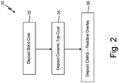
- FIG. 2 illustrates a flowchart of method 30 for applying CMAS-reactive TBC system 10 to a component according to one disclosed non-limiting embodiment. It should be appreciated that alternative and additional steps may be provided without departing from the teaching herein.
- Metallic bond coat 14 is deposited on substrate 12 in step 32.
- Metallic bond coat 14 provides environmental protection for substrate 12 against oxidation, corrosion and improved adhesion along with a thermally grown oxide for ceramic top coat 16.
- metallic bond coat 14 can be an MCrAlY material applied via low pressure plasma spray, however, other bond coat materials and deposition methods may be used.
- Metallic bond coat 14 can generally have a thickness ranging from 50 to several hundred microns.
- Ceramic top coat 16 can be deposited on metallic bond coat 14 in step 34.
- the surface of bond coat 14 can first be prepared for ceramic top coat deposition (e.g., contaminants can be removed and the surface can be grit blasted to provide a desired surface roughness).
- Ceramic top coat 16 can be applied using any of a variety of deposition techniques used to provide a desired microstructure (e.g., desired porosity and vertically-oriented gaps).
- ceramic top coat 16 can be deposited in a manner that provides vertically-oriented gaps to provide needed strain tolerance during operation.
- EB-PVD can provide very narrow vertically-oriented gaps (approximate 1 micron), which can provide high strain tolerance and which can be easily sealed near an upper surface of the coating to limit CMAS-ingress to a small fraction of the coating thickness.
- SPS can also be used to form coatings with columnar microstructures and vertically-oriented gaps. SPS as well as air plasma spraying techniques can be used to form dense vertically-cracked coatings.
- ceramic top coat 16 can be substantially free of vertically-oriented gaps.
- Ceramic top coat 16 can typically have a thickness ranging from 100 to several hundred microns depending on the application. Ceramic top coat 16 can be fully stabilized zirconate/hafnate structures that are phase stable with pure rare earth oxides of the CMAS-reactive overlay 18. In some embodiments, ceramic top coat 16 can have layers of differing chemical compositions. For example, ceramic top coat 16 can have a YSZ inner layer and fully stabilized zirconate/hafnate composition outer layer.
- CMAS-reactive overlay 18 is applied to ceramic top coat 16 in step 36.
- additional surface treatment of ceramic top coat 16 can be provided to prepare ceramic top coat 16.
- thermal exposure can be used to burn off deleterious organics.
- CMAS-reactive overlay 18 can be a pure REO capable of forming a high melting point crystalline precipitate upon reaction with molten CMAS.
- CMAS-reactive overlay 18 can be applied via ALD to form a thin conforming layer over surfaces of ceramic top coat 16, including deep into open pores of the microstructure.
- CMAS-reactive overlay 18 can be applied by other CVD or physical deposition methods (e.g., dipping).
- CMAS-reactive overlay 18 is applied to provide a sufficient concentration of CMAS reactive species to be able to suppress CMAS ingress.
- CMAS-reactive overlay 18 is applied with a thickness that can maintain vertically-oriented gaps while also being capable of limiting molten CMAS ingress to a small fraction of the coating thickness.
- CMAS-reactive overlay 18 can have a thickness of 500 nanometers or less. The thickness can increase for ceramic top coats with larger gap sizes.
- the concentrated rare earth overlay applied to the ceramic TBC in a thin conforming layer can suppress molten CMAS ingress during operation while maintaining strain tolerance of the TBC.
- the increased concentration of CMAS-reactive species at the surface of the TBC reduces the dissolution depth and thereby time required for the molten CMAS to be sufficiently concentrated with reactive species to form a high melting point crystalline precipitate, which seals the TBC from further molten CMAS infiltration.
- any relative terms or terms of degree used herein such as “substantially”, “essentially”, “generally”, “approximately” and the like, should be interpreted in accordance with and subject to any applicable definitions or limits expressly stated herein.
- any relative terms or terms of degree used herein should be interpreted to broadly encompass any relevant disclosed embodiments as well as such ranges or variations as would be understood by a person of ordinary skill in the art in view of the entirety of the present disclosure, such as to encompass ordinary manufacturing tolerance variations, incidental alignment variations, transient alignment or shape variations induced by thermal, rotational or vibrational operational conditions, and the like.
- any relative terms or terms of degree used herein should be interpreted to encompass a range that expressly includes the designated quality, characteristic, parameter or value, without variation, as if no qualifying relative term or term of degree were utilized in the given disclosure or recitation.
- a calcium-magnesium-alumino-silicate (CMAS)-reactive thermal barrier coating includes a ceramic coating and a CMAS-reactive overlay coating.
- the CMAS-reactive overlay coating conforms to a surface of the ceramic coating and comprises a compound that forms a stable high melting point crystalline precipitate when reacted with molten CMAS at a rate that is competitive with CMAS infiltration kinetics into the thermal barrier coating.
- the ceramic coating phase is stable with the CMAS-reactive overlay coating.
- the CMAS-reactive thermal barrier coating of the preceding paragraph can optionally include, additionally and/or alternatively, any one or more of the following features, configurations and/or additional components:
- the CMAS-reactive thermal barrier coating of the preceding paragraph, wherein the CMAS-reactive overlay coating can comprises a material selected from a group consisting of a pure rare earth oxide and a mixed rare earth oxide.
- the ceramic coating can comprise a plurality of vertically-oriented gaps and wherein the CMAS-reactive overlay coating can extend into the gaps and is deposited on inner walls of the ceramic coating, and wherein the plurality of vertically-oriented gaps can remain open.
- the CMAS-reactive thermal barrier coating of any of the preceding paragraphs, wherein the thickness of the CMAS-reactive overlay can range from 10 to 500 nanometers.
- a method of forming a CMAS-reactive thermal barrier coating includes depositing a ceramic coating on a substrate and depositing a CMAS-reactive overlay on the ceramic coating.
- the CMAS-reactive overlay coating conforms to a surface of the ceramic coating and comprises a compound that forms a stable high melting point crystalline precipitate when reacted with molten CMAS at a rate that is competitive with CMAS infiltration kinetics into the thermal barrier coating.
- the ceramic coating phase is stable with the CMAS-reactive overlay coating.
- the method of the preceding paragraph can optionally include, additionally and/or alternatively, any one or more of the following features, configurations, additional components, and/or steps:
- the method of the preceding paragraph, wherein the CMAS-reactive overlay can be deposited using atomic layer deposition.
- the ceramic coating can comprise a plurality of vertically-oriented columnar microstructures extending in a thickness direction of the ceramic coating and wherein the CMAS-reactive overlay can conform to surfaces along a length of the columnar microstructures, and wherein the CMAS-reactive overlay can extend into the vertically-oriented gaps to a depth of at least one-third of a thickness of the ceramic coating from an outer surface of the ceramic coating.
- the CMAS-reactive overlay can have a thickness ranging from 10 to 500 nanometers.
- the plurality of vertically-oriented columnar microstructures can be separated by a plurality of vertically-oriented gaps and wherein the gaps can remain open to a surface of the coating follow deposition of the CMAS-reactive overlay.
- the CMAS-reactive overlay coating can include a material selected from a group consisting of a pure rare earth oxide, a mixed rare earth oxide, and a rare earth aluminate.
- the ceramic coating can comprise a fully stabilized zirconate or hafnate structure.
Landscapes
- Chemical & Material Sciences (AREA)
- Engineering & Computer Science (AREA)
- Materials Engineering (AREA)
- Mechanical Engineering (AREA)
- Chemical Kinetics & Catalysis (AREA)
- Metallurgy (AREA)
- Organic Chemistry (AREA)
- Inorganic Chemistry (AREA)
- Physics & Mathematics (AREA)
- Plasma & Fusion (AREA)
- General Engineering & Computer Science (AREA)
- Ceramic Engineering (AREA)
- General Chemical & Material Sciences (AREA)
- Toxicology (AREA)
- Health & Medical Sciences (AREA)
- Composite Materials (AREA)
- Coating By Spraying Or Casting (AREA)
- Chemical Vapour Deposition (AREA)
Abstract
Description
- The present disclosure relates generally to coatings and more particularly to reactive thermal barrier coatings (TBCs).
- TBCs are conventionally applied to components of gas turbine engines exposed to high temperatures and/or environmental contaminants to protect and extend the life of the components. TBCs can help inhibit oxidation, corrosion, erosion, and other environmental damage to the underlying substrate. During operation, TBCs can be susceptible to damage by environmental dust and debris, including calcium-magnesium-alumino-silicate (CMAS) contaminants. At elevated temperatures, CMAS can melt and infiltrate the porous TBC, which can reduce the strain tolerance of the TBC and promote spallation. The degradation of TBCs is becoming a growing concern as operating temperatures are increased to improve engine efficiency. New and advanced TBCs with improved durability at increasing temperatures are needed.
- In accordance with an aspect of the disclosure, a calcium-magnesium-alumino-silicate (CMAS)-reactive thermal barrier coating includes a ceramic coating and a CMAS-reactive overlay coating. The CMAS-reactive overlay coating conforms to a surface of the ceramic coating and comprises a compound that forms a stable high melting point crystalline precipitate when reacted with molten CMAS at a rate that is competitive with CMAS infiltration kinetics into the thermal barrier coating. The ceramic coating phase is stable with the CMAS-reactive overlay coating.
- The present summary is provided only by way of example, and not limitation. Other aspects of the present disclosure will be appreciated in view of the entirety of the present disclosure, including the entire text, claims and accompanying figures.
-
-
FIG. 1 is a schematic cross-sectional view of one embodiment of a coating. -
FIG. 2 is a flowchart of a method for applying a coating to a component according to one embodiment. - While the above-identified figures set forth embodiments of the present invention, other embodiments are also contemplated, as noted in the discussion. In all cases, this disclosure presents the invention by way of representation and not limitation. It should be understood that numerous other modifications and embodiments can be devised by those skilled in the art, which fall within the scope of the principles of the invention. The figures may not be drawn to scale, and applications and embodiments of the present invention may include features, steps and/or components not specifically shown in the drawings.
- Thermal barrier coatings (TBCs) are conventionally applied to components of gas turbine engines exposed to high temperatures and/or environmental contaminants to protect and extend the life of the components. Conventional TBCs are porous, compliant structures with high strain tolerance. The strain tolerance can be reduced when TBC surface temperatures exceed the melting point (approximately 2200°F) of ingested calcium magnesium-alumino-silicate (CMAS) materials-a temperature that is commonly exceeded on the TBC surface in modern gas turbine engines. Due to its low viscosity, the molten CMAS material can penetrate the TBC, thereby densifying and reducing the compliance of the TBC. The current state-of-the art CMAS-resistant TBC material is gadolinium zirconate (GDZ). The gadolinium in the GDZ reacts with CMAS to precipitate an apatite material. The reaction occurs quickly allowing the apatite reaction product to seal the remainder of the TBC from direct contact with the molten CMAS. Time and temperature increase the rate of attack and therefore improvements beyond GDZ are needed for future higher surface temperature TBC uses.
- The rate limiting step in the GDZ-CMAS reaction is the dissolution rate of gadolinium from the GDZ in a sufficient concentration to react with CMAS. The dissolution time translates directly to the dissolution depth within the TBC layer. The present disclosure is directed to a TBC with a concentrated rare earth overlay, which provides a CMAS reactive species, including but not limited to gadolinium, available for reaction with molten CMAS in high concentrations at the surface of the TBC. The increased concentration of CMAS-reactive species at the surface of the TBC reduces the dissolution depth and thereby time required for the molten CMAS to be sufficiently concentrated with reactive species to form apatite. As discussed further herein, the reactive overlay material can be any apatite-forming material, including but not limited to rare-earth oxides. The reactive overlay is applied to conform to a surface of the TBC including surfaces of internal walls of the TBC formed by columnar gaps open to the TBC surface.
-
FIG. 1 is a schematic cross-sectional view of a CMAS-resistant TBC system 10 applied tosubstrate 12. CMAS-resistant TBC system 10 can includebond coat 14, ceramic top coat (or "ceramic coating") 16, and CMAS-reactive overlay (or "CMAS-reactive overlay coating") 18.Substrate 12 can be a nickel- or cobalt-based superalloy, refractory alloy, or ceramic matrix composite (CMC), as contemplated for use in the manufacture of components for a hot section of a gas turbine engine (e.g., combustor panels and turbine blades, blade outer air seals, and stationary vanes).Bond coat 14 can protectsubstrate 12 from high-temperature oxidation and corrosion and improve adhesion of ceramictop coat 16.Bond coat 14 can be a diffusion or overlay bond coat comprising, for example, an aluminide or MCrAlY (where M can be iron, cobalt, nickel, or a mixture thereof) applied tosubstrate 12, as known in the art. In some embodiments, a surface ofsubstrate 12 and/orbond coat 14 can be roughened, such as by grit blasting or peening, to improve adhesion of TBC ceramictop coat 16. - Ceramic
top coat 16 can include or consist of fully stabilized zirconate/hafnate structures that are phase stable with pure rare earth oxides of CMAS-reactive overlay 18. Fully stabilized zirconate/hafnate structures will have a reduced interaction potential with CMAS-reactive overlay 18. The reduced interaction potential allows a high concentration of the rare earth oxide to remain available in the CMAS-reactive overlay to rapidly dissolve into the molten CMAS and precipitate out stable high melting point phases capable of suppressing further CMAS ingress. Specific chemistries included in ceramictop coat 16 can include pyrochlore/fluorite A2B2O7, where A is of the lanthanide + yttrium group but not necessarily the same as that in the pyrochlore/fluorite (e.g., Gd2Zr2O7), as well as delta phase C4D3O12, where C is of the lanthanide + yttrium group but not necessarily the same as that in the pyrochlore/fluorite (e.g., Y4Zr3O12). - Ceramic
top coat 16 can be deposited onbond coat 14 using any suitable manner to provide a desired microstructure and thickness. Microstructures that provide high strain tolerance can be preferred for high temperature applications. Strain tolerance is generally improved with through-thickness cracks or separations that accommodate thermal expansion.FIG. 1 illustrates a ceramic top coat applied using electron beam physical vapor deposition (EB-PVD), which producescolumnar grains 20 that grow vertically from the surface ofsubstrate 12 with featherlike features. The columnar grains can be separated vertically-oriented gaps 22 over a partial or full vertical thickness of the TBC and can be weakly bonded to each other to accommodate thermal stress. - In other embodiments, ceramic
top coat 16 can be applied using suspension or solution precursor plasma spray techniques (SPS and SPPS). SPS TBCs have been developed as an alternative to TBCs deposited via EB-PVD. SPS techniques can produce coatings having columnar structures similar to those produced by EB-PVD. Unlike EB-PVD coatings, SPS coatings typically have porous columns, which are formed by randomly oriented particle splats. The columns are generally separated by large through-thickness vertically-oriented inter-columnar gaps. The columnar structures can also have horizontally-oriented inter-pass porosity bands or cracks formed between material deposition passes, which can connect vertically-oriented gaps. The generally large vertically-oriented inter-columnar gaps and inter-pass porosity or cracks can accommodate ingress of molten CMAS through the thickness of the ceramic top coat and into the material matrix, substantially compromising the mechanical stability of the ceramic top coat. Alternative dense, vertically cracked TBCs can also be formed with SPS techniques as well as air plasma spray. Dense, vertically cracked coatings can have a more lamellar-appearing structure with through-thickness cracks formed to relieve stress. While cracks can be narrow, parallel facing surfaces extending through a full or nearly full thickness of the coating can provide a substantially straight pathway for molten CMAS infiltration. As used herein, "vertically-oriented" refers to gaps oriented in a direction extending from an inner surface of the coating or a substrate to an outer surface of the coating and is not limited to gaps extending transverse to the substrate. The orientation of vertically-oriented gaps can typically extend at angles between 45° and 90° from the substrate depending on the deposition method. As used throughout the present Specification and Claims, the term "vertically-oriented gaps" encompasses both "inter-columnar gaps," referring to the spaces formed between columnar structures, and vertically-oriented "cracks" formed between columnar structures or in a dense vertically cracked coating. - The present disclosure is not limited to TBCs with columnar microstructures. The disclosed CMAS-reactive overlay can also be applied to dense or porous ceramic top coats without vertical gaps and applied by any known method, although the use of the disclosed CMAS-reactive overlay is particularly beneficial for coatings susceptible to molten CMAS ingress.
- Ceramic
top coat 16 can have a single layer or multiple layers of material (not shown) and can include layers of differing chemical composition. For example, ceramictop coat 16 can include an inner yttrium stabilized zirconia (YSZ) layer deposited onbond coat 14 and an outer GDZ layer deposited on the YSZ layer. YSZ has superior thermochemical compatibility withbond coat 14 and high durability, which makes YSZ desirable for TBC applications. Ceramictop coat 16 can have a thickness ranging from 100 to hundreds of microns. For an EB-PVD ceramic top coat, spacing between adjacent vertically-orientedgaps 22 can be smaller than 1 micron. Vertically-orientedgaps 22 can extend from an outer surface of ceramictop coat 16 to a depth in ceramictop coat 16 equal to a partial or full thickness of ceramictop coat 16. Vertically-oriented gaps in dense vertically cracked coatings can be significantly larger than those formed by EB-PVD. Vertically-oriented gaps between columnar microstructures formed using conventional SPS techniques can be significantly larger than those formed in dense vertically cracked coatings, however, advancements in SPS have provided for significantly reduced gap widths including gap widths of less than 5 microns. - CMAS-
reactive overlay 18 can be a CMAS-reactive compound that forms a stable high melting point crystalline precipitate reaction product (e.g., apatite) at a rate that is competitive with molten CMAS infiltration kinetics. As used herein, a precipitation rate that is competitive with molten CMAS infiltration kinetics refers to a rate of reaction that is substantially equal to or greater than a rate at which the molten CMAS moves through the coating. As such, the CMAS-reactive overlay 18 reacts with the molten CMAS to form a high melting point crystalline precipitate that can seal vertically-oriented gaps and open porosity and suppress further ingress of molten CMAS. CMAS-reactive compounds capable of suppressing ingress of molten CMAS can include pure rare earth oxides (e.g., Gd2O3 or Y2O3), mixed rare earth oxides (e.g., Gd/Y2O3), and rare earth aluminates (e.g., Y4Al2O9 or Y3Al5O12). The viscosity of CMAS is reduced with increased temperature and therefore consideration of the operation temperature should be considered in selection of the CMAS-reactive material. CMAS-reactive overlay 18 can be a pure rare earth oxide (REO). As used herein, the term "rare earth" refers to elements of the lanthanide series as well as yttrium and scandium. Molten CMAS can react with the REO to form a crystallized oxy-apatite phase based on RE8Ca2(SiO4)6O2, which can consume the molten CMAS and solidify. Crystalline apatite precipitates can form at a rate greater than the infiltration of molten CMAS within vertically-orientedgaps 22 and can thereby seal vertically-orientedgaps 22 and suppress further infiltration of molten CMAS into ceramictop coat 16. - CMAS-
reactive overlay 18 can be applied using atomic layer deposition (ALD), which can form a thin conforming layer of CMAS-reactive material on the surfaces of ceramictop coat 16 and extending into open pores. As illustrated inFIG. 1 , CMAS-reactive overlay 18 can conform to the surfaces of the featherlike columnar grains and extend between individual barb-like structures along the length of the columnar grains open to the vertically-oriented gaps between adjacent columnar grains. The use of ALD can provide a uniform surface coverage that allows the CMAS-reactive overlay material to move deeper into inner surfaces of the structure. The thin layer of CMAS-reactive overlay 18 can provide a sufficient concentration of the reactive rare earth element without closinggaps 22 between adjacent columnar grains. As such, the TBC strain tolerance can be maintained with the deposition of CMAS-reactive overlay 18. - The thickness of CMAS-reactive overlay can vary depending on the size of vertically-oriented
gaps 22. For the EB-PVD coating illustrated inFIG. 1 , having an average gap width of approximately 1 micron, CMAS-reactive overlay 18 can have a thickness generally ranging from 100 to 500 nanometers. In some embodiments, and particularly for coatings with verynarrow gaps 22, CMAS-reactive overlay 18 can be less than 100 nanometers and as low as 10 nanometers. CMAS-reactive overlay 18 can be applied with a thickness sufficient to limit molten CMAS ingress to a small fraction of the coating thickness. The thickness of CMAS-reactive overlay 18 can be greater for ceramic top coats having larger vertically-oriented gaps (e.g., ceramic top coats applied by plasma spray techniques). CMAS-reactive overlay 18 can extend a partial to nearly full thickness of ceramictop coat 16. To avoid interaction withbond coat 14 and/orsubstrate 12, it may be desirable to maintain separation between CMAS-reactive overlay 18 andbond coat 14. In some embodiments, CMAS-reactive overlay can extend one-third of the thickness of ceramictop coat 16 from the outer surface. Preferably, CMAS-reactive overlay 18 can extend half of the thickness of ceramictop coat 16. - While ALD is a preferred deposition method for the disclosed EB-PVD coating, given the capability of ALD to form a thin conforming coating layer that can extend deep into open pores, other chemical vapor deposition (CVD) or coating methods may be suitable for some TBC systems. The deposition method must be capable of providing sufficient reacting species near the surface of the coating, and including surfaces separated by vertically-oriented gaps, to compete with a CMAS infiltration rate and thereby provide sufficient protection from CMAS ingress. To maintain strain tolerance, the deposition method should not fill vertically-oriented gaps.
-
FIG. 2 illustrates a flowchart ofmethod 30 for applying CMAS-reactive TBC system 10 to a component according to one disclosed non-limiting embodiment. It should be appreciated that alternative and additional steps may be provided without departing from the teaching herein. -
Metallic bond coat 14 is deposited onsubstrate 12 instep 32.Metallic bond coat 14 provides environmental protection forsubstrate 12 against oxidation, corrosion and improved adhesion along with a thermally grown oxide for ceramictop coat 16. Typically,metallic bond coat 14 can be an MCrAlY material applied via low pressure plasma spray, however, other bond coat materials and deposition methods may be used.Metallic bond coat 14 can generally have a thickness ranging from 50 to several hundred microns. - Ceramic
top coat 16 can be deposited onmetallic bond coat 14 instep 34. In some embodiments, the surface ofbond coat 14 can first be prepared for ceramic top coat deposition (e.g., contaminants can be removed and the surface can be grit blasted to provide a desired surface roughness). Ceramictop coat 16 can be applied using any of a variety of deposition techniques used to provide a desired microstructure (e.g., desired porosity and vertically-oriented gaps). Preferably, ceramictop coat 16 can be deposited in a manner that provides vertically-oriented gaps to provide needed strain tolerance during operation. EB-PVD can provide very narrow vertically-oriented gaps (approximate 1 micron), which can provide high strain tolerance and which can be easily sealed near an upper surface of the coating to limit CMAS-ingress to a small fraction of the coating thickness. SPS can also be used to form coatings with columnar microstructures and vertically-oriented gaps. SPS as well as air plasma spraying techniques can be used to form dense vertically-cracked coatings. In some embodiments, ceramictop coat 16 can be substantially free of vertically-oriented gaps. - Ceramic
top coat 16 can typically have a thickness ranging from 100 to several hundred microns depending on the application. Ceramictop coat 16 can be fully stabilized zirconate/hafnate structures that are phase stable with pure rare earth oxides of the CMAS-reactive overlay 18. In some embodiments, ceramictop coat 16 can have layers of differing chemical compositions. For example, ceramictop coat 16 can have a YSZ inner layer and fully stabilized zirconate/hafnate composition outer layer. - CMAS-
reactive overlay 18 is applied to ceramictop coat 16 instep 36. In some embodiments, additional surface treatment of ceramictop coat 16 can be provided to prepare ceramictop coat 16. For example, thermal exposure can be used to burn off deleterious organics. CMAS-reactive overlay 18 can be a pure REO capable of forming a high melting point crystalline precipitate upon reaction with molten CMAS. - CMAS-
reactive overlay 18 can be applied via ALD to form a thin conforming layer over surfaces of ceramictop coat 16, including deep into open pores of the microstructure. In other embodiments, CMAS-reactive overlay 18 can be applied by other CVD or physical deposition methods (e.g., dipping). CMAS-reactive overlay 18 is applied to provide a sufficient concentration of CMAS reactive species to be able to suppress CMAS ingress. CMAS-reactive overlay 18 is applied with a thickness that can maintain vertically-oriented gaps while also being capable of limiting molten CMAS ingress to a small fraction of the coating thickness. Typically, for an EB-PVD ceramic top coat, CMAS-reactive overlay 18 can have a thickness of 500 nanometers or less. The thickness can increase for ceramic top coats with larger gap sizes. - The concentrated rare earth overlay applied to the ceramic TBC in a thin conforming layer can suppress molten CMAS ingress during operation while maintaining strain tolerance of the TBC. The increased concentration of CMAS-reactive species at the surface of the TBC reduces the dissolution depth and thereby time required for the molten CMAS to be sufficiently concentrated with reactive species to form a high melting point crystalline precipitate, which seals the TBC from further molten CMAS infiltration.
- Any relative terms or terms of degree used herein, such as "substantially", "essentially", "generally", "approximately" and the like, should be interpreted in accordance with and subject to any applicable definitions or limits expressly stated herein. In all instances, any relative terms or terms of degree used herein should be interpreted to broadly encompass any relevant disclosed embodiments as well as such ranges or variations as would be understood by a person of ordinary skill in the art in view of the entirety of the present disclosure, such as to encompass ordinary manufacturing tolerance variations, incidental alignment variations, transient alignment or shape variations induced by thermal, rotational or vibrational operational conditions, and the like. Moreover, any relative terms or terms of degree used herein should be interpreted to encompass a range that expressly includes the designated quality, characteristic, parameter or value, without variation, as if no qualifying relative term or term of degree were utilized in the given disclosure or recitation.
- The following are non-exclusive descriptions of possible embodiments of the present invention.
- A calcium-magnesium-alumino-silicate (CMAS)-reactive thermal barrier coating includes a ceramic coating and a CMAS-reactive overlay coating. The CMAS-reactive overlay coating conforms to a surface of the ceramic coating and comprises a compound that forms a stable high melting point crystalline precipitate when reacted with molten CMAS at a rate that is competitive with CMAS infiltration kinetics into the thermal barrier coating. The ceramic coating phase is stable with the CMAS-reactive overlay coating.
- The CMAS-reactive thermal barrier coating of the preceding paragraph can optionally include, additionally and/or alternatively, any one or more of the following features, configurations and/or additional components:
The CMAS-reactive thermal barrier coating of the preceding paragraph, wherein the CMAS-reactive overlay coating can comprises a material selected from a group consisting of a pure rare earth oxide and a mixed rare earth oxide. - The CMAS-reactive thermal barrier coating of any of the preceding paragraphs, wherein the CMAS-reactive overlay coating can be a rare earth aluminate.
- The CMAS-reactive thermal barrier coating of any of the preceding paragraphs, wherein the ceramic coating can comprise a fully stabilized zirconate or hafnate structure.
- The CMAS-reactive thermal barrier coating of any of the preceding paragraphs, wherein the ceramic coating can comprise gadolinium zirconate.
- The CMAS-reactive thermal barrier coating of any of the preceding paragraphs, wherein the ceramic coating can comprise yttrium zirconate.
- The CMAS-reactive thermal barrier coating of any of the preceding paragraphs, wherein the ceramic coating can comprise a plurality of vertically-oriented gaps and wherein the CMAS-reactive overlay coating can extend into the gaps and is deposited on inner walls of the ceramic coating, and wherein the plurality of vertically-oriented gaps can remain open.
- The CMAS-reactive thermal barrier coating of any of the preceding paragraphs, wherein the CMAS-reactive overlay can be deposited in pores open to the vertically-oriented gaps.
- The CMAS-reactive thermal barrier coating of any of the preceding paragraphs, wherein the thickness of the CMAS-reactive overlay can range from 10 to 500 nanometers.
- The CMAS-reactive thermal barrier coating of any of the preceding paragraphs, wherein the CMAS-reactive overlay can extend into the vertically-oriented gaps to a depth of at least one-third of a thickness of the ceramic coating from an outer surface of the ceramic coating.
- The CMAS-reactive thermal barrier coating of any of the preceding paragraphs, wherein the CMAS-reactive overlay can extend into the vertically-oriented gaps to a depth of at least one-half of a thickness of the ceramic coating from an outer surface of the ceramic coating.
- The CMAS-reactive thermal barrier coating of any of the preceding paragraphs, wherein the CMAS-reactive overlay can have a material composition that will react with molten CMAS to form an oxy-apatite phase.
- A method of forming a CMAS-reactive thermal barrier coating includes depositing a ceramic coating on a substrate and depositing a CMAS-reactive overlay on the ceramic coating. The CMAS-reactive overlay coating conforms to a surface of the ceramic coating and comprises a compound that forms a stable high melting point crystalline precipitate when reacted with molten CMAS at a rate that is competitive with CMAS infiltration kinetics into the thermal barrier coating. The ceramic coating phase is stable with the CMAS-reactive overlay coating.
- The method of the preceding paragraph can optionally include, additionally and/or alternatively, any one or more of the following features, configurations, additional components, and/or steps:
The method of the preceding paragraph, wherein the CMAS-reactive overlay can be deposited using atomic layer deposition. - The method of any of the preceding paragraphs, wherein the ceramic coating can be applied by electron beam-physical vapor deposition.
- The method of any of the preceding paragraphs, wherein the ceramic coating can comprise a plurality of vertically-oriented columnar microstructures extending in a thickness direction of the ceramic coating and wherein the CMAS-reactive overlay can conform to surfaces along a length of the columnar microstructures, and wherein the CMAS-reactive overlay can extend into the vertically-oriented gaps to a depth of at least one-third of a thickness of the ceramic coating from an outer surface of the ceramic coating.
- The method of any of the preceding paragraphs, wherein the CMAS-reactive overlay can have a thickness ranging from 10 to 500 nanometers.
- The method of any of the preceding paragraphs, wherein the plurality of vertically-oriented columnar microstructures can be separated by a plurality of vertically-oriented gaps and wherein the gaps can remain open to a surface of the coating follow deposition of the CMAS-reactive overlay.
- The method of any of the preceding paragraphs, wherein the CMAS-reactive overlay coating can include a material selected from a group consisting of a pure rare earth oxide, a mixed rare earth oxide, and a rare earth aluminate.
- The method of any of the preceding paragraphs, wherein the ceramic coating can comprise a fully stabilized zirconate or hafnate structure.
- While the invention has been described with reference to an exemplary embodiment(s), it will be understood by those skilled in the art that various changes may be made and equivalents may be substituted for elements thereof without departing from the scope of the invention. In addition, many modifications may be made to adapt a particular situation or material to the teachings of the invention without departing from the essential scope thereof. Therefore, it is intended that the invention not be limited to the particular embodiment(s) disclosed, but that the invention will include all embodiments falling within the scope of the appended claims.
Claims (15)
- A calcium-magnesium-alumino-silicate (CMAS)-reactive thermal barrier coating comprising:a ceramic coating (16); anda CMAS-reactive overlay coating (18), wherein the CMAS-reactive overlay coating (18) conforms to a surface of the ceramic coating (16) and comprises a compound that forms a stable high melting point crystalline precipitate when reacted with molten CMAS at a rate that is competitive with CMAS infiltration kinetics into the thermal barrier coating;wherein the ceramic coating phase is stable with the CMAS-reactive overlay coating (18).
- The CMAS-reactive thermal barrier coating of claim 1, wherein the CMAS-reactive overlay coating (18) comprises a material selected from a group consisting of a pure rare earth oxide and a mixed rare earth oxide.
- The CMAS-reactive thermal barrier coating of claim 1, wherein the CMAS-reactive overlay coating (18) is a rare earth aluminate.
- The CMAS-reactive thermal barrier coating of claim 1 or 2, wherein the ceramic coating (16) comprises a fully stabilized zirconate or hafnate structure, gadolinium zirconate, or yttrium zirconate.
- The CMAS-reactive thermal barrier coating of any preceding claim, wherein the ceramic coating (16) comprises a plurality of vertically-oriented gaps (22) and wherein the CMAS-reactive overlay coating (18) extends into the gaps (22) and is deposited on inner walls of the ceramic coating (16), and wherein the plurality of vertically-oriented gaps (22) remain open, and wherein, optionally, the CMAS-reactive overlay coating (18) is deposited in pores open to the vertically-oriented gaps (22).
- The CMAS-reactive thermal barrier coating of claim 5, wherein the CMAS-reactive overlay coating (18) extends into the vertically-oriented gaps (22) to a depth of at least one-third or at least one-half of a thickness of the ceramic coating (16) from an outer surface of the ceramic coating (16).
- The CMAS-reactive thermal barrier coating of any preceding claim, wherein the thickness of the CMAS-reactive overlay coating (18) ranges from 10 to 500 nanometers.
- The CMAS-reactive thermal barrier coating of any preceding claim, wherein the CMAS-reactive overlay coating (18) has a material composition that will react with molten CMAS to form an oxy-apatite phase.
- A method (30) of forming a CMAS-reactive thermal barrier coating, the method (30) comprising:depositing a ceramic coating (16) on a substrate (12); anddepositing a CMAS-reactive overlay coating (18) on the ceramic coating (16), wherein the CMAS-reactive overlay coating (18) conforms to a surface of the ceramic coating (16) and comprises a compound that forms a stable high melting point crystalline precipitate when reacted with molten CMAS at a rate that is competitive with CMAS infiltration kinetics into the thermal barrier coating;wherein the ceramic coating phase is stable with the CMAS-reactive overlay coating (18).
- The method (30) of claim 9, wherein the CMAS-reactive overlay coating (18) is deposited using atomic layer deposition.
- The method (30) of claim 9 or 10, wherein the ceramic coating (16) is applied by electron beam-physical vapor deposition.
- The method (30) of any of claims 9 to 11, wherein the ceramic coating (16) comprises a plurality of vertically-oriented columnar microstructures extending in a thickness direction of the ceramic coating (16) and wherein the CMAS-reactive overlay coating (18) conforms to surfaces along a length of the columnar microstructures, and wherein the CMAS-reactive overlay coating (18) extends into the vertically-oriented gaps (22) to a depth of at least one-third of a thickness of the ceramic coating (16) from an outer surface of the ceramic coating (16).
- The method (30) of claim 12, wherein the plurality of vertically-oriented columnar microstructures are separated by a plurality of vertically-oriented gaps (22) and wherein the gaps (22) remain open to a surface of the coating follow deposition of the CMAS-reactive overlay coating (18).
- The method (30) of any of claims 9 to 13, wherein the CMAS-reactive overlay coating (18) has a thickness ranging from 10 to 500 nanometers.
- The method (30) of any of claims 9 to 14, wherein the CMAS-reactive overlay coating (18) comprises a material selected from a group consisting of a pure rare earth oxide, a mixed rare earth oxide, and a rare earth aluminate and/or wherein the ceramic coating (16) comprises a fully stabilized zirconate or hafnate structure.
Applications Claiming Priority (1)
| Application Number | Priority Date | Filing Date | Title |
|---|---|---|---|
| US201962864624P | 2019-06-21 | 2019-06-21 |
Publications (1)
| Publication Number | Publication Date |
|---|---|
| EP3754049A1 true EP3754049A1 (en) | 2020-12-23 |
Family
ID=71108451
Family Applications (1)
| Application Number | Title | Priority Date | Filing Date |
|---|---|---|---|
| EP20180747.6A Pending EP3754049A1 (en) | 2019-06-21 | 2020-06-18 | Reactive thermal barrier coating |
Country Status (2)
| Country | Link |
|---|---|
| US (2) | US11795829B2 (en) |
| EP (1) | EP3754049A1 (en) |
Cited By (2)
| Publication number | Priority date | Publication date | Assignee | Title |
|---|---|---|---|---|
| EP4446299A1 (en) * | 2023-04-14 | 2024-10-16 | RTX Corporation | Environmental barrier coating and method of applying the same |
| EP4520850A1 (en) * | 2023-09-11 | 2025-03-12 | RTX Corporation | Rare earth-phosphate-enhanced thermal barrier coating |
Families Citing this family (6)
| Publication number | Priority date | Publication date | Assignee | Title |
|---|---|---|---|---|
| FR3090698B1 (en) * | 2018-12-20 | 2021-04-09 | Safran | AERONAUTICAL PART RESISTANT TO MELTED SAND |
| EP3754049A1 (en) * | 2019-06-21 | 2020-12-23 | Raytheon Technologies Corporation | Reactive thermal barrier coating |
| CN116477970A (en) * | 2023-03-05 | 2023-07-25 | 广西大学 | A preparation method for in-situ generation of rare earth apatite phase dense reaction layer resistant to CMAS corrosion |
| CN117026137A (en) * | 2023-08-14 | 2023-11-10 | 兰州理工大学 | A columnar structure thermal barrier coating ceramic layer and its preparation method |
| WO2026035826A1 (en) | 2024-08-06 | 2026-02-12 | Rtx Corporation | Hybrid coating for enhanced cmas resistance of thermal barrier coating |
| CN120330654B (en) * | 2025-06-16 | 2025-09-05 | 北矿新材科技有限公司 | CMAS corrosion resistant thermal barrier coating and preparation method thereof |
Citations (3)
| Publication number | Priority date | Publication date | Assignee | Title |
|---|---|---|---|---|
| US20180119270A1 (en) * | 2016-10-31 | 2018-05-03 | General Electric Company | Articles for high temperature service and methods for making |
| EP3453779A1 (en) * | 2017-09-08 | 2019-03-13 | United Technologies Corporation | Multi layer cmas resistant thermal barrier coating |
| EP3453784A1 (en) * | 2017-09-08 | 2019-03-13 | United Technologies Corporation | Coating with dense columns separated by gaps |
Family Cites Families (7)
| Publication number | Priority date | Publication date | Assignee | Title |
|---|---|---|---|---|
| US6296945B1 (en) | 1999-09-10 | 2001-10-02 | Siemens Westinghouse Power Corporation | In-situ formation of multiphase electron beam physical vapor deposited barrier coatings for turbine components |
| KR20050060345A (en) | 2003-12-16 | 2005-06-22 | 삼성전자주식회사 | Patterned source and method for depositing thin film by using the same |
| US7807231B2 (en) * | 2005-11-30 | 2010-10-05 | General Electric Company | Process for forming thermal barrier coating resistant to infiltration |
| DE102010015470A1 (en) * | 2010-04-16 | 2011-10-20 | Forschungszentrum Jülich GmbH | Process for the internal coating of functional layers with a tempering material |
| US10179945B2 (en) | 2013-12-16 | 2019-01-15 | General Electric Company | CMAS resistant thermal barrier coatings |
| US9920417B2 (en) | 2014-10-27 | 2018-03-20 | General Electric Company | Article and method of making thereof |
| EP3754049A1 (en) * | 2019-06-21 | 2020-12-23 | Raytheon Technologies Corporation | Reactive thermal barrier coating |
-
2020
- 2020-06-18 EP EP20180747.6A patent/EP3754049A1/en active Pending
- 2020-06-19 US US16/906,298 patent/US11795829B2/en active Active
-
2023
- 2023-09-20 US US18/370,648 patent/US12196109B2/en active Active
Patent Citations (3)
| Publication number | Priority date | Publication date | Assignee | Title |
|---|---|---|---|---|
| US20180119270A1 (en) * | 2016-10-31 | 2018-05-03 | General Electric Company | Articles for high temperature service and methods for making |
| EP3453779A1 (en) * | 2017-09-08 | 2019-03-13 | United Technologies Corporation | Multi layer cmas resistant thermal barrier coating |
| EP3453784A1 (en) * | 2017-09-08 | 2019-03-13 | United Technologies Corporation | Coating with dense columns separated by gaps |
Cited By (2)
| Publication number | Priority date | Publication date | Assignee | Title |
|---|---|---|---|---|
| EP4446299A1 (en) * | 2023-04-14 | 2024-10-16 | RTX Corporation | Environmental barrier coating and method of applying the same |
| EP4520850A1 (en) * | 2023-09-11 | 2025-03-12 | RTX Corporation | Rare earth-phosphate-enhanced thermal barrier coating |
Also Published As
| Publication number | Publication date |
|---|---|
| US20240011402A1 (en) | 2024-01-11 |
| US12196109B2 (en) | 2025-01-14 |
| US11795829B2 (en) | 2023-10-24 |
| US20200400028A1 (en) | 2020-12-24 |
Similar Documents
| Publication | Publication Date | Title |
|---|---|---|
| US12196109B2 (en) | Reactive thermal barrier coating | |
| EP2766504B1 (en) | Thermal barrier coating systems and processes therefor | |
| EP3074619B1 (en) | Method of providing a self-healing coating | |
| US9023486B2 (en) | Thermal barrier coating systems and processes therefor | |
| EP2596068B1 (en) | Thermal barrier coatings including c mas-resistant thermal barrier coating layers | |
| US9945036B2 (en) | Hot corrosion-resistant coatings and components protected therewith | |
| EP2208805B1 (en) | Strain tolerant thermal barrier coating system | |
| EP3453781B1 (en) | Cmas-resistant thermal barrier coating and method of making a coating thereof | |
| US9920417B2 (en) | Article and method of making thereof | |
| US20200024718A1 (en) | Cmas resistant thermal barrier coatings | |
| US9790587B2 (en) | Article and method of making thereof | |
| EP1249515A2 (en) | Yttria-stabilized zirconia with reduced thermal conductivity | |
| EP1852521A1 (en) | Thermal barrier coatings and processes for applying same | |
| US11549382B2 (en) | Restoration coating system and method | |
| JP2006347870A (en) | Process for producing corrosion-resistant EBC bond coats and the like for silicon-containing substrates | |
| US10364701B2 (en) | CMAS barrier coating for a gas turbine engine having a reactive material that reacts with a layer of environmental contaminant compositions and method of applying the same | |
| EP4174213A1 (en) | Cmas reactive thermal barrier coating | |
| EP1666627A2 (en) | Low thermal conductivity thermal barrier coating system and method therefor |
Legal Events
| Date | Code | Title | Description |
|---|---|---|---|
| PUAI | Public reference made under article 153(3) epc to a published international application that has entered the european phase |
Free format text: ORIGINAL CODE: 0009012 |
|
| STAA | Information on the status of an ep patent application or granted ep patent |
Free format text: STATUS: THE APPLICATION HAS BEEN PUBLISHED |
|
| AK | Designated contracting states |
Kind code of ref document: A1 Designated state(s): AL AT BE BG CH CY CZ DE DK EE ES FI FR GB GR HR HU IE IS IT LI LT LU LV MC MK MT NL NO PL PT RO RS SE SI SK SM TR |
|
| AX | Request for extension of the european patent |
Extension state: BA ME |
|
| STAA | Information on the status of an ep patent application or granted ep patent |
Free format text: STATUS: REQUEST FOR EXAMINATION WAS MADE |
|
| 17P | Request for examination filed |
Effective date: 20210617 |
|
| RBV | Designated contracting states (corrected) |
Designated state(s): AL AT BE BG CH CY CZ DE DK EE ES FI FR GB GR HR HU IE IS IT LI LT LU LV MC MK MT NL NO PL PT RO RS SE SI SK SM TR |
|
| RAP3 | Party data changed (applicant data changed or rights of an application transferred) |
Owner name: RTX CORPORATION |
|
| STAA | Information on the status of an ep patent application or granted ep patent |
Free format text: STATUS: EXAMINATION IS IN PROGRESS |
|
| 17Q | First examination report despatched |
Effective date: 20240205 |