EP3753850A1 - Anti-torque rotor for a helicopter - Google Patents
Anti-torque rotor for a helicopter Download PDFInfo
- Publication number
- EP3753850A1 EP3753850A1 EP19180441.8A EP19180441A EP3753850A1 EP 3753850 A1 EP3753850 A1 EP 3753850A1 EP 19180441 A EP19180441 A EP 19180441A EP 3753850 A1 EP3753850 A1 EP 3753850A1
- Authority
- EP
- European Patent Office
- Prior art keywords
- axis
- control rod
- respect
- mast
- rotor
- Prior art date
- Legal status (The legal status is an assumption and is not a legal conclusion. Google has not performed a legal analysis and makes no representation as to the accuracy of the status listed.)
- Granted
Links
Images


Classifications
-
- B—PERFORMING OPERATIONS; TRANSPORTING
- B64—AIRCRAFT; AVIATION; COSMONAUTICS
- B64C—AEROPLANES; HELICOPTERS
- B64C27/00—Rotorcraft; Rotors peculiar thereto
- B64C27/82—Rotorcraft; Rotors peculiar thereto characterised by the provision of an auxiliary rotor or fluid-jet device for counter-balancing lifting rotor torque or changing direction of rotorcraft
-
- B—PERFORMING OPERATIONS; TRANSPORTING
- B64—AIRCRAFT; AVIATION; COSMONAUTICS
- B64C—AEROPLANES; HELICOPTERS
- B64C11/00—Propellers, e.g. of ducted type; Features common to propellers and rotors for rotorcraft
- B64C11/30—Blade pitch-changing mechanisms
- B64C11/32—Blade pitch-changing mechanisms mechanical
-
- B—PERFORMING OPERATIONS; TRANSPORTING
- B64—AIRCRAFT; AVIATION; COSMONAUTICS
- B64C—AEROPLANES; HELICOPTERS
- B64C27/00—Rotorcraft; Rotors peculiar thereto
- B64C27/54—Mechanisms for controlling blade adjustment or movement relative to rotor head, e.g. lag-lead movement
- B64C27/58—Transmitting means, e.g. interrelated with initiating means or means acting on blades
- B64C27/59—Transmitting means, e.g. interrelated with initiating means or means acting on blades mechanical
- B64C27/605—Transmitting means, e.g. interrelated with initiating means or means acting on blades mechanical including swash plate, spider or cam mechanisms
-
- B—PERFORMING OPERATIONS; TRANSPORTING
- B64—AIRCRAFT; AVIATION; COSMONAUTICS
- B64C—AEROPLANES; HELICOPTERS
- B64C27/00—Rotorcraft; Rotors peculiar thereto
- B64C27/54—Mechanisms for controlling blade adjustment or movement relative to rotor head, e.g. lag-lead movement
- B64C27/78—Mechanisms for controlling blade adjustment or movement relative to rotor head, e.g. lag-lead movement in association with pitch adjustment of blades of anti-torque rotor
-
- F—MECHANICAL ENGINEERING; LIGHTING; HEATING; WEAPONS; BLASTING
- F16—ENGINEERING ELEMENTS AND UNITS; GENERAL MEASURES FOR PRODUCING AND MAINTAINING EFFECTIVE FUNCTIONING OF MACHINES OR INSTALLATIONS; THERMAL INSULATION IN GENERAL
- F16C—SHAFTS; FLEXIBLE SHAFTS; ELEMENTS OR CRANKSHAFT MECHANISMS; ROTARY BODIES OTHER THAN GEARING ELEMENTS; BEARINGS
- F16C19/00—Bearings with rolling contact, for exclusively rotary movement
- F16C19/52—Bearings with rolling contact, for exclusively rotary movement with devices affected by abnormal or undesired conditions
-
- F—MECHANICAL ENGINEERING; LIGHTING; HEATING; WEAPONS; BLASTING
- F16—ENGINEERING ELEMENTS AND UNITS; GENERAL MEASURES FOR PRODUCING AND MAINTAINING EFFECTIVE FUNCTIONING OF MACHINES OR INSTALLATIONS; THERMAL INSULATION IN GENERAL
- F16C—SHAFTS; FLEXIBLE SHAFTS; ELEMENTS OR CRANKSHAFT MECHANISMS; ROTARY BODIES OTHER THAN GEARING ELEMENTS; BEARINGS
- F16C21/00—Combinations of sliding-contact bearings with ball or roller bearings, for exclusively rotary movement
-
- F—MECHANICAL ENGINEERING; LIGHTING; HEATING; WEAPONS; BLASTING
- F16—ENGINEERING ELEMENTS AND UNITS; GENERAL MEASURES FOR PRODUCING AND MAINTAINING EFFECTIVE FUNCTIONING OF MACHINES OR INSTALLATIONS; THERMAL INSULATION IN GENERAL
- F16C—SHAFTS; FLEXIBLE SHAFTS; ELEMENTS OR CRANKSHAFT MECHANISMS; ROTARY BODIES OTHER THAN GEARING ELEMENTS; BEARINGS
- F16C39/00—Relieving load on bearings
- F16C39/02—Relieving load on bearings using mechanical means
-
- B—PERFORMING OPERATIONS; TRANSPORTING
- B64—AIRCRAFT; AVIATION; COSMONAUTICS
- B64C—AEROPLANES; HELICOPTERS
- B64C27/00—Rotorcraft; Rotors peculiar thereto
- B64C27/54—Mechanisms for controlling blade adjustment or movement relative to rotor head, e.g. lag-lead movement
-
- F—MECHANICAL ENGINEERING; LIGHTING; HEATING; WEAPONS; BLASTING
- F16—ENGINEERING ELEMENTS AND UNITS; GENERAL MEASURES FOR PRODUCING AND MAINTAINING EFFECTIVE FUNCTIONING OF MACHINES OR INSTALLATIONS; THERMAL INSULATION IN GENERAL
- F16C—SHAFTS; FLEXIBLE SHAFTS; ELEMENTS OR CRANKSHAFT MECHANISMS; ROTARY BODIES OTHER THAN GEARING ELEMENTS; BEARINGS
- F16C2326/00—Articles relating to transporting
- F16C2326/43—Aeroplanes; Helicopters
Definitions
- the present invention relates to an anti-torque rotor for a helicopter.
- Helicopters are known to basically comprise a fuselage, a main rotor positioned on the top of the fuselage and rotating about an axis of its own, and an anti-torque rotor located at the tail end of the fuselage.
- Helicopters also comprise, in a known manner, one or more power units, such as turbines for example, and a transmission unit interposed between the turbines and the main rotor adapted to transmit motive power from the turbines to the main rotor.
- power units such as turbines for example
- transmission unit interposed between the turbines and the main rotor adapted to transmit motive power from the turbines to the main rotor.
- the anti-torque rotor in turn, basically comprises:
- the mast of the anti-torque rotor is driven in rotation by a set of gears driven by the main transmission unit.
- the blades of the anti-torque rotor rotate integrally with the mast about the first axis and can be selectively tilted about the second axis, so as to be able to alter the respective angles of attack and consequently adjust the thrust exerted by the anti-torque rotor.
- anti-torque rotors comprise:
- the antifriction bearing comprises:
- the rolling bodies allow rotation of the outer ring with respect to the inner ring and the consequent rotation of the control element with respect to the rod.
- Operation of the pedal causes the control rod to slide parallel to the first axis. This sliding causes, via the antifriction bearing, the control element to slide parallel to the first axis along a given path of travel.
- This sliding causes rotation of the blades about the associated second axes, so as to alter the respective angles of attack by equal amounts associated with the given path of travel.
- a first failure situation might occur in the case where rolling bodies and/or the raceways of the inner or outer rings become damaged, for example due to the accidental introduction of foreign bodies inside the bearing, the loss of lubricating grease, or damage to the raceways or surfaces of the rolling bodies.
- a second failure situation might occur in the case where the rolling bodies break with consequent detachment of the inner ring from the rolling bodies.
- the bearing would no longer be slidable parallel to the first axis, and the rod would no longer cause translation of the control element.
- US-B-9,359,073 describes an anti-torque rotor for a helicopter according to the preamble of claim 1.
- US-B-9,359,073 describes an anti-torque rotor comprising a mast, a rod, and a first and second bearing arranged in series.
- the first bearing comprises a first ring rotating with the mast and a second ring.
- the second bearing comprises a third ring and a fourth ring.
- the third ring of the second bearing and the first ring of the first bearing are connected to each other in a non-rotatable manner.
- the anti-torque rotor also comprises a locking device interposed between the third and the fourth ring and adapted to prevent rotation of the third ring with respect to fourth ring.
- This locking device comprises an element that is breakable in the case of the first bearing failure and not breakable in the case of correct operation of the first bearing.
- the object of the present invention is to provide an anti-torque rotor that enables satisfying at least one of the aforementioned needs in a simple and inexpensive manner.
- reference numeral 1 indicates, in particular, a helicopter basically comprising:
- the helicopter 1 also comprises a transmission unit 11, which transmits motive power from the turbines 5 to the main rotor 3.
- the transmission unit 11 comprises:
- rotor 3 is adapted to provide orientable thrust that enables lift-off and forward flight of the helicopter 1.
- Rotor 4 generates a thrust, which causes a counter torque on the fuselage 2.
- This counter torque is directed in the opposite direction to the torque exerted by rotor 3.
- rotor 4 basically comprises:
- the blades 8 are hinged on the hub 9 so as to be:
- the hub 9 comprises a plurality of connection elements 27 projecting radially with respect to axis A for connection to the respective blades 8.
- Each blade 8 also comprises a root portion 14 arranged radially inward with respect to axis A and hinged on the associated connection element 27 of the hub 9.
- the rotor 4 also comprises:
- the mast 6 is hollow.
- the mast 6 also comprises ( Figures 4 and 5 ) :
- the main portion 22 also defines a flange 19 adapted to receive motive power from the shaft 13.
- the mast 6 has a maximum diameter at the flange 19, and a progressively decreasing diameter proceeding from the flange 19 towards the ends 20 and 21.
- the rod 10 is partly housed inside the mast 6.
- the rod 10 also comprises:
- the main body 25 is operatively connected to the flight control 15 by a lever mechanism (not shown) or by a wireless control link.
- Element 16 in turn, comprises ( Figure 5 ):
- Flange 42 and the bearing 17 are housed outside the mast 6 and surround the rod 10.
- flange 42 and the bearing 17 are arranged on the end opposite to ends 20 and 23 with respect to ends 21 and 24.
- Flange 42 is connected to the mast 6 by a single, variable-length bellows coupling 44, which enables sliding along the axis A.
- the levers 43 are generally inclined with respect to axis A and extend from flange 42 towards ends 20 and 23.
- levers 43 are hinged on the root portions 14 of the respective blades 8.
- the bearing 17 is able to transmit axial loads parallel to axis A in both directions.
- the bearing 17 is configured in such a way that translation of the rod 10 along axis A in both directions causes the translation of element 16 in the same directions.
- the bearing 17 thus defines a transmission unit, which connects the rod 10 and element 16 in an axially integral and angularly movable manner with respect to axis A.
- ring 31 has two shoulders 35 and 36 at mutually opposite sides, projecting radially towards ring 30 and defining respective axial abutment surfaces for the rolling bodies 32.
- the rolling bodies 32 are, in particular, axially interposed between the shoulders 35 and 36.
- ring 31 is made in two half-rings, arranged axially in contact with each other in the case shown.
- Ring 30 comprises a shoulder 37 axially interposed between shoulders 35 and 36, projecting radially towards ring 31 and defining respective abutment surfaces for the rolling bodies 32.
- Shoulder 37 is axially interposed between the rolling bodies 32 on a plane of symmetry of the bearing 17 radial to axis A.
- outer ring 30 is fastened on the tubular body 40 of element 16 on the opposite side to flange 42 in a direction radial to axis A.
- the rotor 4 also comprises a further motive power transmission unit 45 operatively connected to the rod 10 and to element 16.
- Transmission unit 45 is available:
- transmission unit 45 is set in the active configuration in the event of failure of the bearing 17.
- the term "failure" of the bearing 17 means any operating condition in which the bearing 17 is no longer able to transmit an axial load from the rod 10 to element 16, i.e. to cause the axial translation in both directions of element 16, following the axial translation of the rod 10.
- a first "failure" operating condition occurs when inner ring 31 of the bearing 17 is driven in rotation by the rolling bodies 32 and, due to friction, generates a twisting moment on the rod 10.
- a second "failure" operating condition occurs when the rolling bodies 32 of the bearing 17 breaks, so that the rod 10 becomes axially movable with respect to element 16.
- the transmission unit 45 is set in the inactive configuration when the bearing 17 correctly allows the relative rotation of element 16 with respect to the rod 10 and prevents any relative translation between element 16 and the rod 10.
- the rotor 4 also comprises detection means 50, which comprise:
- Transmission unit 45 basically comprises ( Figures 4 and 5 ):
- the ridge 61 is delimited in the axial direction by two walls 65 and 66 opposite to each other.
- the ridge 61 has a trapezoidal profile and comprises a further wall 67 axially interposed between walls 65 and 66.
- wall 67 extends parallel to axis A.
- walls 65 and 66 are inclined to one another with respect to axis A, lying on respective planes converging on the opposite side of axis A with respect to the rod 10, and extend symmetrically with respect to a plane radial to axis A.
- Seat 64 is delimited in the axial direction by two walls 71 and 72 opposite to each other.
- seat 64 also has a trapezoidal profile and comprises a further wall 73 axially interposed between walls 71 and 72.
- wall 73 extends parallel to axis A.
- walls 71 and 72 are inclined to one another with respect to axis A, lying on respective planes converging on the opposite side of axis A with respect to the rod 10, and extending symmetrically with respect to a plane radial to axis A.
- the ridge 61 engages the seat 64 with axial and radial play with respect to axis A.
- the ridge 61 is axially set apart from seat 64, i.e. both walls 66 and 67 of the ridge 61 are set apart from the respective walls 71 and 72 of the seat 64, as shown in Figure 5 .
- the ridge 61 makes axial contact with the seat 64. More specifically, wall 71 makes contact with wall 65, or wall 72 makes contact with wall 66, ensuring that the sliding of the rod 10 in both directions parallel to axis A causes element 16 to slide in both directions.
- wall 73 of the seat 64 is radially set apart from wall 67 of the ridge 61.
- cylindrical body 60 is connected to the rod 10 by a threaded connection 80.
- Transmission unit 45 also comprises a lock nut 81, which is screwed onto the rod 10 and is arranged in axial abutment against the cylindrical body 60 on the end axially opposite to the bearing 17.
- lock nut 81 is screwed on end 24 of the rod 10.
- Ring 63 is formed by two half-rings 82 and 83, which are in axial contact with each other.
- half-ring 83 is axially interposed between half-ring 82 and the bearing 17.
- Half-ring 83 is also in axial contact with the bearing 17.
- the half-rings 82 and 83 define respective portions of the seat 64.
- the ridge 61 and the seat 64 are coated with a low friction material 150.
- wall 71 makes contact with wall 65, or wall 72 makes contact with wall 66.
- the rotor 4 also comprises a sleeve 90, radially interposed between ring 31 and the rod 10, and axially interposed between the rod 10 and the cylindrical body 60.
- the sleeve 90 extend coaxially to the rod 10.
- the sleeve 90 basically comprises:
- the main body 91 comprises:
- the ridge 92 defines an axial end of the sleeve 90 facing towards end 23 of the rod 10 and arranged in abutment against an annular shoulder 121 of the rod 10.
- the cylindrical body 60 also comprises an end surface 140, extending radially and arranged in contact with ring 31.
- the rotor 4 comprises an interface 120 made of an antifriction material interposed between the rod 10 and the bearing 17, so as to allow rotation of the entire bearing 17 with respect to the rod 10 about axis A, in the event of failure of the bearing 17.
- the interface 120 comprises a first coating in an antifriction material extending axially and arranged on the surface 94 of the sleeve 90 and on surface 18 of the rod 10.
- the interface 120 also comprises a second coating extending radially on shoulder 121 and on surface 122 of the ridge 92 in contact with shoulder 121 and axially opposite to ring 31 of the bearing 17.
- the interface 120 is adapted to prevent undesired rotation of the rod 10 about axis A. This undesired rotation could occur if, following a failure condition of the bearing 17, the rolling bodies 32 transmit a twisting moment to ring 31, and consequently, by friction, to the sleeve 90.
- the sleeve 90 is made of steel and surfaces 93 are 94 are coated with a hard tungsten oxide.
- the sleeve 90 is made of bronze and has a structure with cavities that entrap lubricant.
- the material of surface 18 and surfaces 93 and 94 has a coefficient of friction such as to avoid, in the aforementioned failure condition, the undesired rotation of the sleeve 90 transmitting a twisting moment to the rod 10 sufficient to cause undesired rotation of the rod 10.
- the interface 120 also comprises a third coating deposited on surface 140 in contact with ring 31 of the bearing 17.
- Ring 30 of the bearing 17 is axially secured, by respective parts axially opposite to each other, between the tubular body 40 of element 16 and ring 63.
- Ring 31 of the bearing 17 is axially secured, by respective parts axially opposite to each other, between the ridge 92 of the sleeve 90 and the cylindrical body 60.
- the detection means 50 also comprise a sensor 53 adapted to generate a third signal associated with the rotation of the sleeve 90 about axis A.
- the senor 51 is adapted to detect at least one of the temperature and acceleration of the bearing 17 and/or the sleeve 90.
- operation of rotor 3 In use, operation of rotor 3 generates thrust that enables sustaining the helicopter 1 in the air and forward flight of the helicopter 1.
- Operation of rotor 3 also generates torque on the fuselage 2 that is balanced by the counter-torque generated by the thrust of rotor 4.
- the pilot operates flight control 15, so as to adjust the pitch of the blades 8 of rotor 4, and consequently the thrust generated by rotor 4.
- the mast 6 is driven in rotation about axis A by the shaft 13 and drives the hub 9, element 16 and the blades 8 in rotation about axis A.
- the rod 10, instead, remains angularly fixed with respect to axis A.
- operation of flight control 15 causes translation of the rod 10 in a given direction along axis A.
- This translation causes integral translation of the bearing 17 and element 16 along axis A.
- element 16 moves away from (or closer to) the blades 8 and changes the inclination of the levers 43 with respect to axis B, increasing (or decreasing) the angle of attack of the blades 18.
- the rolling bodies 32 improperly transfer a twisting moment to ring 31, and therefore to the sleeve 90, the first and second coatings of the interface 120 prevent the rod 10 from being driven in rotation.
- the antifriction material of surfaces 94 and 18 forming the first coating and of surface 122 and shoulder 121 forming the second coating, prevents the undesired rotation of the sleeve 90 from transmitting a twisting moment to the rod 10 sufficient to cause undesired rotation of the rod 10.
- the antifriction material of the third coating of the interface 120 deposited on surface 140 prevents undesired rotation of ring 31 of the bearing 17 from causing undesired rotation of ring 63 and the rod 10.
- sensor 53 In the event of undesired rotation of the sleeve 90, sensor 53 generates the third signal, which informs the pilot of the hazard condition.
- sensor 51 detects the temperature and acceleration of the bearing 17 and of sleeve 90 and, in cases where these values implicate a failure state of the bearing 17, generates the first signal.
- walls 65 and 66 of the ridge 61 are axially set apart from the respective walls 71 and 72 of the seat 64, as shown in Figure 5 .
- the transmission unit 45 formed by the cylindrical body 60 and ring 63 does not perform an active role in the transmission of movement from the rod 10 to element 16.
- the bearing 17 is no longer able to transmit an axial load from the rod 10 to element 16, i.e. to cause integral translation of the rod 10 and element 16 parallel to axis A.
- transmission unit 45 is activated, which enables preserving controllability of the anti-torque rotor 4, at least for a predetermined period of time.
- operation of flight control 15 causes translation of the rod 10 and ring 63 up to a position where the ridge 61 makes axial contact with the seat 64 of ring 63. More specifically, wall 65 (66) of the ridge 61 first makes contact with and then axially pushes wall 71 (72) of the seat 64 of ring 63.
- the transmission unit 45 is in the active configuration, and translation of the rod 10 continues to cause the translation of element 16, via the cylindrical body 60 and ring 63.
- Activation of transmission unit 45 generates a small amount of play on element 16 corresponding to the over-travel that the rod 10 must cover to bring the ridge 61 into abutment against the seat 64.
- Sensor 52 generates the second signal, which informs the pilot that transmission unit 45 is in the active configuration.
- reference numeral 4' indicates an anti-torque rotor according to a second embodiment of the present invention.
- Rotor 4' is similar to rotor 4 and will be described below only with regard to the differences from the latter; where possible, identical or equivalent parts of rotors 4 and 4' will be indicated with the same reference numerals.
- rotor 4' differs from rotor 4 in that, in order to reduce friction between the ridge 61 and the seat 64, it comprises:
- the bearings 100 and 101 are roller or ball or needle bearings.
- each bearing 100 (101) comprises:
- the rings 103 and 104 are of a truncated-cone type.
- the rolling bodies 105 are needles having respective axes inclined with respect to axis A.
- rotor 4' The operation of rotor 4' is similar to that of rotor 4 and is therefore not described in detail.
- Sensor 53 generates the third signal, which informs the pilot of the hazard condition and that it is advisable to land as soon as possible.
- transmission unit 45 when set in the active configuration, causes element 16 to slide, following the translation of the rod 10 parallel to axis A.
- transmission unit 45 defines an additional and redundant transmission path of control from the rod 10 to element 16 with respect to the bearing 17.
- transmission unit 45 ensures controllability of the angle of attack of the blades 8, even in the event of failure of the bearing 17.
- sensor 52 Once the ridge 61 is in abutment against the seat 64, sensor 52 generates the second signal, which informs the pilot that transmission unit 45 is in the active configuration. In this way, the pilot is informed that it is advisable to land as soon as possible.
- the interface 102 could comprise only one or two of the first, second and third coatings.
Landscapes
- Engineering & Computer Science (AREA)
- Mechanical Engineering (AREA)
- General Engineering & Computer Science (AREA)
- Aviation & Aerospace Engineering (AREA)
- Transmission Devices (AREA)
Abstract
Description
- The present invention relates to an anti-torque rotor for a helicopter.
- Helicopters are known to basically comprise a fuselage, a main rotor positioned on the top of the fuselage and rotating about an axis of its own, and an anti-torque rotor located at the tail end of the fuselage.
- Helicopters also comprise, in a known manner, one or more power units, such as turbines for example, and a transmission unit interposed between the turbines and the main rotor adapted to transmit motive power from the turbines to the main rotor.
- In greater detail, the anti-torque rotor, in turn, basically comprises:
- a mast rotatable about a first axis;
- a hub rotatable about the first axis; and
- a plurality of blades hinged on said hub, projecting in a cantilever fashion from the hub and each extending along respective second axes transversal to the first axis.
- The mast of the anti-torque rotor is driven in rotation by a set of gears driven by the main transmission unit.
- The blades of the anti-torque rotor rotate integrally with the mast about the first axis and can be selectively tilted about the second axis, so as to be able to alter the respective angles of attack and consequently adjust the thrust exerted by the anti-torque rotor.
- In order to adjust the angles of attack of the respective blades, anti-torque rotors comprise:
- a rod, operatively connected to a pedal operable by the pilot through a mechanical connection or fly-by-wire link and sliding inside the mast along the first axis, but angularly fixed with respect to the first axis;
- a control element, also known as a "spider", integrally rotating with the mast about the first axis and equipped with a plurality of arms connected to respective blades in an eccentric position with respect to the associated second axes; and
- an antifriction bearing, mounted in a sliding manner with respect to first axis, interposed between the rod and control element, and configured so as to transmit an axial load from the rod to the control element.
- More specifically, the antifriction bearing, in turn, comprises:
- a radially outer ring fastened on the control element;
- a radially inner ring fastened to the control rod; and
- a plurality of rolling bodies, which roll in respective raceways defined by the radially inner and outer rings.
- In a normal operating condition of the bearing, the rolling bodies allow rotation of the outer ring with respect to the inner ring and the consequent rotation of the control element with respect to the rod.
- Operation of the pedal causes the control rod to slide parallel to the first axis. This sliding causes, via the antifriction bearing, the control element to slide parallel to the first axis along a given path of travel.
- This sliding causes rotation of the blades about the associated second axes, so as to alter the respective angles of attack by equal amounts associated with the given path of travel.
- From the foregoing, it follows that a possible failure of the antifriction bearing would risk making the anti-torque rotor effectively uncontrollable, causing a hazardous situation for the helicopter.
- In particular, a first failure situation might occur in the case where rolling bodies and/or the raceways of the inner or outer rings become damaged, for example due to the accidental introduction of foreign bodies inside the bearing, the loss of lubricating grease, or damage to the raceways or surfaces of the rolling bodies.
- In this condition, instead of allowing the relative rotation of the control element to the control rod, the antifriction bearing would improperly transfer a twisting moment, progressively growing over time, from the outer ring to the inner ring.
- This twisting moment would be transmitted to the control rod, generating a risk of damaging the control rod.
- Regarding this first failure situation, there is awareness in the industry of the need to reduce the risk that these twisting moments could irreversibly damage the control rod.
- A second failure situation might occur in the case where the rolling bodies break with consequent detachment of the inner ring from the rolling bodies. In this case, the bearing would no longer be slidable parallel to the first axis, and the rod would no longer cause translation of the control element.
- There is awareness in the industry of the need to promptly detect the failure state of the antifriction bearing, so that the pilot can quickly land before the helicopter becomes completely uncontrollable.
- There is also awareness in the industry of the need to ensure correct control of the anti-torque rotor, even in the event of failure of the antifriction bearing.
-
US-B-9,359,073 - In greater detail,
US-B-9,359,073 - The first bearing comprises a first ring rotating with the mast and a second ring.
- The second bearing comprises a third ring and a fourth ring.
- The third ring of the second bearing and the first ring of the first bearing are connected to each other in a non-rotatable manner.
- The anti-torque rotor also comprises a locking device interposed between the third and the fourth ring and adapted to prevent rotation of the third ring with respect to fourth ring. This locking device comprises an element that is breakable in the case of the first bearing failure and not breakable in the case of correct operation of the first bearing.
- The solution shown in
US-B-9,359,073 - The object of the present invention is to provide an anti-torque rotor that enables satisfying at least one of the aforementioned needs in a simple and inexpensive manner.
- The aforesaid object is achieved by the present invention, in so far as it relates to an anti-torque rotor as defined in claim 1.
- For a better understanding of the present invention, two preferred embodiments are described hereinafter, purely by way of non-limitative example and with reference to the accompanying drawings, in which:
-
Figure 1 is a perspective view of a helicopter comprising an anti-torque rotor according to a first embodiment of the present invention; -
Figures 2 and3 are respectively a top view and a perspective view of the anti-torque rotor inFigure 1 ; -
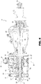
Figure 4 is a section along the line IV-IV inFigure 2 ; -
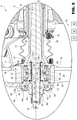
Figure 5 is an enlarged view of certain details inFigure 4 ; and -
Figure 6 shows, on a highly enlarged scale, further details of a second embodiment of the anti-torque rotor inFigures 1 to 5 . - Referring to
Figure 1 , reference numeral 1 indicates, in particular, a helicopter basically comprising: - a
fuselage 2; - one or
more turbines 5; - a
main rotor 3 positioned on the top of thefuselage 2 and rotatable about an axis A; and - an
anti-torque rotor 4 located at a tail end of thefuselage 2 and rotatable about an axis of its own, transversal to axis A. - The helicopter 1 also comprises a
transmission unit 11, which transmits motive power from theturbines 5 to themain rotor 3. - In turn, the
transmission unit 11 comprises: - a
gear train 12, which transmits motive power from theturbine 5 to therotor 3; and - a
shaft 13, which transmits motive power from thegear train 12 torotor 4. - In a known manner,
rotor 3 is adapted to provide orientable thrust that enables lift-off and forward flight of the helicopter 1. -
Rotor 4 generates a thrust, which causes a counter torque on thefuselage 2. - This counter torque is directed in the opposite direction to the torque exerted by
rotor 3. - According to the amount of thrust generated by
rotor 4, it is therefore possible to orient the helicopter 1 according to a desired yaw angle, or vary said yaw angle depending on the manoeuvre that it is wished to perform. - Referring to
Figures 2 to 5 ,rotor 4 basically comprises: - a
mast 6 rotatable about an axis A and operatively connected to theshaft 13 in a known manner; - a plurality of
blades 8, numbering three in the case shown, which extend in a cantilever fashion along respective axes B transversal to axis A; and - a
hub 9 externally fastened to a portion of themast 6, integrally rotating with themast 6 about axis A and on which theblades 8 are hinged. - More specifically, the
blades 8 are hinged on thehub 9 so as to be: - integrally rotatable with the
hub 9 and themast 6 about axis A; and - tiltable about their respective axes B by the same angles and simultaneously in time, so as to vary the respective angles of attack.
- In particular, the
hub 9 comprises a plurality ofconnection elements 27 projecting radially with respect to axis A for connection to therespective blades 8. Eachblade 8 also comprises aroot portion 14 arranged radially inward with respect to axis A and hinged on the associatedconnection element 27 of thehub 9. - In order to vary the aforementioned angles of attack, the
rotor 4 also comprises: - a flight control 15 (only schematically shown in
Figure 1 ) operable by the pilot, for example a pedal; - a
control rod 10 sliding parallel to axis A and operable by theflight control 15, by means of a mechanical connection or a fly-by-wire method; - an
element 16 rotating integrally with themast 6 about axis A and connected to theblades 8 in an eccentric manner with respect to the associated axes B; and - a
bearing 17 interposed between therod 10 andelement 16 and sliding, jointly with therod 10, parallel to axis A. - More specifically, the
mast 6 is hollow. - The
mast 6 also comprises (Figures 4 and5 ) : - an
axial end 20; - an
axial end 21, open and opposite to end 20; and - a
main portion 22 interposed between the axial ends 20 and 21 and on which thehub 9 is fitted. - The
main portion 22 also defines aflange 19 adapted to receive motive power from theshaft 13. - More specifically, the
mast 6 has a maximum diameter at theflange 19, and a progressively decreasing diameter proceeding from theflange 19 towards theends - The
rod 10 is partly housed inside themast 6. - The
rod 10 also comprises: - an
end 23; - an
end 24, axially opposite to end 23; and - a
main body 25 running throughends mast 6. Ends 23 and 24 are located externally to themast 6 and on the sides ofends - The
main body 25 is operatively connected to theflight control 15 by a lever mechanism (not shown) or by a wireless control link. -
Element 16, in turn, comprises (Figure 5 ): - a
tubular body 40, partly housed in themast 6 and connected to themast 6 in a sliding manner with respect to axis A, and partly housing therod 10; - a
flange 42 extending orthogonally to axis A and fastened to thetubular body 40 on the end opposite to themast 6; and - a plurality of levers 43 (
Figure 4 ) hinged onflange 42 about respective axes C transversal to axis A and hinged onrespective blades 8 in eccentric positions with respect to the associated axes B. -
Flange 42 and thebearing 17 are housed outside themast 6 and surround therod 10. - More specifically,
flange 42 and thebearing 17 are arranged on the end opposite to ends 20 and 23 with respect to ends 21 and 24. -
Flange 42 is connected to themast 6 by a single, variable-length bellowscoupling 44, which enables sliding along the axis A. - The
levers 43 are generally inclined with respect to axis A and extend fromflange 42 towards ends 20 and 23. - The translation of the
rod 10 along axis A causes, via thebearing 17, the translation ofelement 16. - Following the sliding of
element 16 along axis A, thelevers 43 change their inclination with respect to axis A by the same mutually identical angles, causing the simultaneous rotation of theblades 8 about their respective axes B by the same mutually equal angles. - In particular, the
levers 43 are hinged on theroot portions 14 of therespective blades 8. - The
bearing 17 is able to transmit axial loads parallel to axis A in both directions. - In other words, the
bearing 17 is configured in such a way that translation of therod 10 along axis A in both directions causes the translation ofelement 16 in the same directions. - The bearing 17 thus defines a transmission unit, which connects the
rod 10 andelement 16 in an axially integral and angularly movable manner with respect to axis A. - The
bearing 17, in turn, comprises: - an
outer ring 30 integrally rotating withelement 16; - an
inner ring 31 integrally sliding with therod 10; and - a plurality of rolling
bodies 32, a double ring of balls in the case shown, rolling onrespective raceways respective rings - In the case shown,
ring 31 has twoshoulders ring 30 and defining respective axial abutment surfaces for the rollingbodies 32. The rollingbodies 32 are, in particular, axially interposed between theshoulders - Furthermore,
ring 31 is made in two half-rings, arranged axially in contact with each other in the case shown. -
Ring 30 comprises ashoulder 37 axially interposed betweenshoulders ring 31 and defining respective abutment surfaces for the rollingbodies 32.Shoulder 37 is axially interposed between the rollingbodies 32 on a plane of symmetry of thebearing 17 radial to axis A. - Furthermore,
outer ring 30 is fastened on thetubular body 40 ofelement 16 on the opposite side to flange 42 in a direction radial to axis A. - The
rotor 4 also comprises a further motivepower transmission unit 45 operatively connected to therod 10 and toelement 16. -
Transmission unit 45 is available: - in an active configuration, in which it causes
element 16 to slide along axis A, following the translation of saidrod 10 along axis A; or - in an inactive configuration, in which it is disengaged from
element 16. - In greater detail,
transmission unit 45 is set in the active configuration in the event of failure of thebearing 17. - Hereinafter in this description, the term "failure" of the
bearing 17 means any operating condition in which thebearing 17 is no longer able to transmit an axial load from therod 10 toelement 16, i.e. to cause the axial translation in both directions ofelement 16, following the axial translation of therod 10. - By way of non-limitative example, a first "failure" operating condition occurs when
inner ring 31 of thebearing 17 is driven in rotation by the rollingbodies 32 and, due to friction, generates a twisting moment on therod 10. - A second "failure" operating condition occurs when the rolling
bodies 32 of thebearing 17 breaks, so that therod 10 becomes axially movable with respect toelement 16. - Otherwise, the
transmission unit 45 is set in the inactive configuration when the bearing 17 correctly allows the relative rotation ofelement 16 with respect to therod 10 and prevents any relative translation betweenelement 16 and therod 10. - The
rotor 4 also comprises detection means 50, which comprise: - a
sensor 51 adapted to generate a first signal associated with the failure of thebearing 17; and/or - a
sensor 52 adapted to generate a second signal associated with thetransmission unit 45 being in the active configuration. -
Transmission unit 45 basically comprises (Figures 4 and5 ): - a
cylindrical body 60, a nut in the case shown, integral with therod 10 and comprising anannular ridge 61 projecting radially from the side opposite to therod 10; and - a
ring 63 integral withelement 16 and provided with aseat 64 open towards axis A and engaged by theridge 61. - The
ridge 61 is delimited in the axial direction by twowalls - In the case shown, the
ridge 61 has a trapezoidal profile and comprises afurther wall 67 axially interposed betweenwalls wall 67 extends parallel to axis A. - In particular,
walls rod 10, and extend symmetrically with respect to a plane radial to axis A. -
Seat 64 is delimited in the axial direction by twowalls - In the case shown,
seat 64 also has a trapezoidal profile and comprises afurther wall 73 axially interposed betweenwalls wall 73 extends parallel to axis A. Similarly towalls walls rod 10, and extending symmetrically with respect to a plane radial to axis A. - The
ridge 61 engages theseat 64 with axial and radial play with respect to axis A. - More specifically, when the
transmission unit 45 is set in the inactive configuration, theridge 61 is axially set apart fromseat 64, i.e. bothwalls ridge 61 are set apart from therespective walls seat 64, as shown inFigure 5 . - Contrariwise, when
transmission unit 45 is set in the active configuration, theridge 61 makes axial contact with theseat 64. More specifically,wall 71 makes contact withwall 65, orwall 72 makes contact withwall 66, ensuring that the sliding of therod 10 in both directions parallel to axis A causeselement 16 to slide in both directions. - Furthermore,
wall 73 of theseat 64 is radially set apart fromwall 67 of theridge 61. - In particular, the
cylindrical body 60 is connected to therod 10 by a threadedconnection 80. -
Transmission unit 45 also comprises alock nut 81, which is screwed onto therod 10 and is arranged in axial abutment against thecylindrical body 60 on the end axially opposite to thebearing 17. - In particular, the
lock nut 81 is screwed onend 24 of therod 10. -
Ring 63 is formed by two half-rings - More specifically, half-
ring 83 is axially interposed between half-ring 82 and thebearing 17. - Half-
ring 83 is also in axial contact with thebearing 17. - The half-
rings seat 64. - In particular, the
ridge 61 and theseat 64 are coated with alow friction material 150. - More specifically,
wall 71 makes contact withwall 65, orwall 72 makes contact withwall 66. - Preferably, the
rotor 4 also comprises asleeve 90, radially interposed betweenring 31 and therod 10, and axially interposed between therod 10 and thecylindrical body 60. - In greater detail, the
sleeve 90 extend coaxially to therod 10. - The
sleeve 90 basically comprises: - a
main body 91; and - an
axial end ridge 92, which has a diameter greater than themain body 91 and projects radially from themain body 91 towardselement 16 from the side opposite to axis A. - In greater detail, the
main body 91 comprises: - a radially
outer surface 93 that makes contact withring 31 of thebearing 17; and - a radially
inner surface 94 that makes contact with asurface 18 of therod 10 radially external with respect to axis A. - The
ridge 92 defines an axial end of thesleeve 90 facing towardsend 23 of therod 10 and arranged in abutment against anannular shoulder 121 of therod 10. - The
cylindrical body 60 also comprises anend surface 140, extending radially and arranged in contact withring 31. - Advantageously, the
rotor 4 comprises aninterface 120 made of an antifriction material interposed between therod 10 and thebearing 17, so as to allow rotation of theentire bearing 17 with respect to therod 10 about axis A, in the event of failure of thebearing 17. - The
interface 120 comprises a first coating in an antifriction material extending axially and arranged on thesurface 94 of thesleeve 90 and onsurface 18 of therod 10. - The
interface 120 also comprises a second coating extending radially onshoulder 121 and onsurface 122 of theridge 92 in contact withshoulder 121 and axially opposite to ring 31 of thebearing 17. - The
interface 120 is adapted to prevent undesired rotation of therod 10 about axis A. This undesired rotation could occur if, following a failure condition of thebearing 17, the rollingbodies 32 transmit a twisting moment to ring 31, and consequently, by friction, to thesleeve 90. - In the case shown, the
sleeve 90 is made of steel and surfaces 93 are 94 are coated with a hard tungsten oxide. - Alternatively, the
sleeve 90 is made of bronze and has a structure with cavities that entrap lubricant. - The material of
surface 18 and surfaces 93 and 94 has a coefficient of friction such as to avoid, in the aforementioned failure condition, the undesired rotation of thesleeve 90 transmitting a twisting moment to therod 10 sufficient to cause undesired rotation of therod 10. - The
interface 120 also comprises a third coating deposited onsurface 140 in contact withring 31 of thebearing 17. -
Ring 30 of thebearing 17 is axially secured, by respective parts axially opposite to each other, between thetubular body 40 ofelement 16 andring 63. -
Ring 31 of thebearing 17 is axially secured, by respective parts axially opposite to each other, between theridge 92 of thesleeve 90 and thecylindrical body 60. - The detection means 50 also comprise a
sensor 53 adapted to generate a third signal associated with the rotation of thesleeve 90 about axis A. - Furthermore, the
sensor 51 is adapted to detect at least one of the temperature and acceleration of thebearing 17 and/or thesleeve 90. - In use, operation of
rotor 3 generates thrust that enables sustaining the helicopter 1 in the air and forward flight of the helicopter 1. - Operation of
rotor 3 also generates torque on thefuselage 2 that is balanced by the counter-torque generated by the thrust ofrotor 4. - In order to control the yaw angle of the helicopter 1, the pilot operates
flight control 15, so as to adjust the pitch of theblades 8 ofrotor 4, and consequently the thrust generated byrotor 4. - During operation of
rotor 4, themast 6 is driven in rotation about axis A by theshaft 13 and drives thehub 9,element 16 and theblades 8 in rotation about axis A. Therod 10, instead, remains angularly fixed with respect to axis A. - The operation of
rotor 4 is described below, starting from a condition in which thebearing 17 works correctly andtransmission unit 45 is consequently set in the inactive configuration. - In this condition, operation of
flight control 15 causes translation of therod 10 in a given direction along axis A. - This translation causes integral translation of the
bearing 17 andelement 16 along axis A. - In consequence,
element 16 moves away from (or closer to) theblades 8 and changes the inclination of thelevers 43 with respect to axis B, increasing (or decreasing) the angle of attack of theblades 18. - This movement of the
levers 43 causes the simultaneous rotation by equal angles of theblades 8 about the associated axes B and the consequent adjustment of the angles of attack of theblades 8. - If, following failure of the
bearing 17, the rollingbodies 32 improperly transfer a twisting moment to ring 31, and therefore to thesleeve 90, the first and second coatings of theinterface 120 prevent therod 10 from being driven in rotation. - More specifically, the antifriction material, of
surfaces surface 122 andshoulder 121 forming the second coating, prevents the undesired rotation of thesleeve 90 from transmitting a twisting moment to therod 10 sufficient to cause undesired rotation of therod 10. - The antifriction material of the third coating of the
interface 120 deposited onsurface 140 prevents undesired rotation ofring 31 of the bearing 17 from causing undesired rotation ofring 63 and therod 10. - In the event of undesired rotation of the
sleeve 90,sensor 53 generates the third signal, which informs the pilot of the hazard condition. - In addition,
sensor 51 detects the temperature and acceleration of thebearing 17 and ofsleeve 90 and, in cases where these values implicate a failure state of thebearing 17, generates the first signal. - Furthermore, in the above-described condition,
walls ridge 61 are axially set apart from therespective walls seat 64, as shown inFigure 5 . - In consequence, the
transmission unit 45 formed by thecylindrical body 60 andring 63 does not perform an active role in the transmission of movement from therod 10 toelement 16. - In the event of failure, the
bearing 17 is no longer able to transmit an axial load from therod 10 toelement 16, i.e. to cause integral translation of therod 10 andelement 16 parallel to axis A. - In this situation,
transmission unit 45 is activated, which enables preserving controllability of theanti-torque rotor 4, at least for a predetermined period of time. - In greater detail, operation of
flight control 15 causes translation of therod 10 andring 63 up to a position where theridge 61 makes axial contact with theseat 64 ofring 63. More specifically, wall 65 (66) of theridge 61 first makes contact with and then axially pushes wall 71 (72) of theseat 64 ofring 63. - In this way, the
transmission unit 45 is in the active configuration, and translation of therod 10 continues to cause the translation ofelement 16, via thecylindrical body 60 andring 63. - Activation of
transmission unit 45 generates a small amount of play onelement 16 corresponding to the over-travel that therod 10 must cover to bring theridge 61 into abutment against theseat 64. -
Sensor 52 generates the second signal, which informs the pilot thattransmission unit 45 is in the active configuration. - Referring to
Figure 6 , reference numeral 4' indicates an anti-torque rotor according to a second embodiment of the present invention. - Rotor 4' is similar to
rotor 4 and will be described below only with regard to the differences from the latter; where possible, identical or equivalent parts ofrotors 4 and 4' will be indicated with the same reference numerals. - In particular, rotor 4' differs from
rotor 4 in that, in order to reduce friction between theridge 61 and theseat 64, it comprises: - a
bearing 100 interposed betweenwall 65 ofridge 61 andwall 71 of theseat 64; and - a
bearing 101 interposed betweenwall 66 of theridge 61 andwall 72 of theseat 64. - Preferably, the
bearings - In particular, each bearing 100 (101) comprises:
- a
ring 103 fastened to wall 66 (67); - a
ring 104 fastened to wall 71 (72); and - a plurality of rolling
bodies 105, which are interposed between therings - In the case shown, the
rings - In the case shown, the rolling
bodies 105 are needles having respective axes inclined with respect to axis A. - The operation of rotor 4' is similar to that of
rotor 4 and is therefore not described in detail. - From examination of the characteristics of the
rotor 4 and 4' according to the present invention, the advantages that can be achieved therewith are evident. - If the rolling
bodies 32 improperly transmit a twisting moment to ring 31 and thesleeve 90, causing them to rotate following failure of thebearing 17, the interface 102 in antifriction material substantially limits the risk of this twisting moment being transmitted to therod 10. - In this way, the risk that the
rod 10 becomes damaged by this twisting moment and thatrotor 4 or 4' consequently becomes uncontrollable is substantially limited, without adding further bearings, unlike the solutions of known type mentioned in the introductory part of this description. -
Sensor 53 generates the third signal, which informs the pilot of the hazard condition and that it is advisable to land as soon as possible. - In particular, when set in the active configuration,
transmission unit 45 causeselement 16 to slide, following the translation of therod 10 parallel to axis A. - Due to this,
transmission unit 45 defines an additional and redundant transmission path of control from therod 10 toelement 16 with respect to thebearing 17. - In this way,
transmission unit 45 ensures controllability of the angle of attack of theblades 8, even in the event of failure of thebearing 17. - More specifically, in the case of damage to the rolling
bodies 32 that results in physical separation ofrings rod 10 brings theridge 61 into abutment against theseat 64. In this way, the correct translation ofelement 16 and the consequent controllability of the angle of attack of theblades 8 and therotor 4 are ensured. - Once the
ridge 61 is in abutment against theseat 64,sensor 52 generates the second signal, which informs the pilot thattransmission unit 45 is in the active configuration. In this way, the pilot is informed that it is advisable to land as soon as possible. - Finally, it is clear that modifications and variants can be made with regard to the
rotor 4 and 4' described and illustrated herein without departing from the scope defined by the claims. - In particular, the interface 102 could comprise only one or two of the first, second and third coatings.
Claims (15)
- An anti-torque rotor (4, 4') for a helicopter (1), comprising:- a mast (6), rotatable about a first axis (A);- a plurality of blades (8), hinged on said mast (6), extending along respective second axes (B) transversal to said first axis (A) and rotatable about respective said second axes (B) to alter the respective angles of attack;- a control element (16), sliding along said first axis (A) with respect to said mast (6), integrally rotating with said mast (6), and operatively connected to said blades (8) to cause the rotation of said blades (8) about respective said second axes (B) following a translation of said element (16) along said axis (A) ;- a control rod (10), sliding axially along said first axis (A) with respect to said mast (6) and angularly fixed with respect to said first axis (A); and- a connection element (17), interposed between said control rod (10) and said control element (16), sliding along said first axis (A) with respect to said mast (6) and integrally with said control rod (10), and configured to enable the relative rotation of said control element (16) with respect to said control rod (10) about said first axis (A) in a correct operating condition; characterized in that it comprises an interface (120) made of an antifriction material interposed between said control rod (10) and said connection element (17), so as to enable the rotation of said connection element (17) with respect to said control rod (10) about said first axis (A) in the event of failure of said connection element (17).
- A rotor according to claim 1, characterized in that it comprises a tubular element (90) radially interposed between said control rod (10) and said connection element (17), and axially sliding integrally with said control rod (10) and said connection element (17);
said interface (120) comprising at least a first surface (94) of said tubular element (90), which is arranged is contact with said control rod (10), so as to enable the rotation of said tubular element (90) jointly with said connection element (17), with respect to said control rod (10). - A rotor according to claim 2, characterized in that said interface (120) comprises the entire said tubular element (90).
- A rotor according to claim 2 or 3, characterized in that said interface (120) comprises a second surface (18) of said control rod (10) having an axial extension and arranged in contact with said first surface (94).
- A rotor according to any of claims 2 to 4, characterized in that said tubular element (90), in turn, comprises:- a main body (91) radially interposed between said connection element (17) and said control rod (10); and- a first axial end ridge (92), which radially projects from said main body (91) towards said connection element (17).
- A rotor according to claim 5, characterized in that said interface (120) further comprises a third surface (122) of said first ridge (92) arranged in abutment against a shoulder (121) of said control rod (10).
- A rotor according to claim 6, characterized in that said interface (120) further comprises said shoulder (121) of said control rod (10) in contact with said third surface (122).
- A rotor according to any of claims 2 to 7, characterized in that it comprises at least a first sensor (53) adapted to detect the rotation of said annular element (90).
- A rotor according to any of claims 2 to 8, characterized in that said connection element (17) comprises an antifriction bearing (17);
said bearing (17), in turn, comprising:- a first ring (30) integrally rotating with said control element (16) about said first axis (A);- a second ring (31) radially internal to said first ring (30) with respect to said first axis (A) and integrally sliding with said control rod (10) along said first axis (A); and- a plurality of rolling bodies (32), which are interposed between said first and second rings (30, 31) and adapted to roll on respective raceways (33, 34) of said first and second rings (31, 32);said second ring (31) being in contact with said tubular element (90) on the side opposite to said rolling bodies (32) along a direction radial to said first axis (A). - A rotor according to any of the preceding claims, characterized in that it comprises a transmission unit (45), which is operatively connected to said control rod (10) and to said control element (16);
said transmission unit (45) being selectively available:- in an active configuration, wherein it causes said control element (16) to slide, following the translation of said control rod (16), along said first axis (A); or- in an inactive configuration, wherein it is disengaged from said control element (16). - A rotor according to claim 10, characterized in that said transmission unit (45) is arranged in said active configuration in the event of failure of said connection element (17);
said transmission unit (45) being arranged in said inactive configuration when said connection element (17) enables relative rotation of said control element (16) with respect to said control rod (10). - A rotor according to claim 10 or 11, characterized in that it comprises a second sensor (52) adapted to generate a signal associated with the fact of said transmission unit (45) being in said active configuration.
- A rotor according to claim 11 or 12, characterized in that said transmission unit (45), in turn, comprises:- a second annular ridge (61), axially integral with said control rod (10) and radially projecting from said control rod (10); and- a seat (64) engaged by said second ridge (61) and angularly integral with said control element (16).
- A rotor according to claim 13, when dependent upon any of claims 5 to 12, characterized in that said transmission unit (45) comprises a sleeve (60) mounted coaxially on said control rod (10) and from which said second ridge (61) projects from the side radially opposite to said control rod (10);
said second ring (31) being axially blocked between said sleeve (60) and said first radially projecting ridge (92) of said tubular element (90);
said interface (120) comprising a fourth surface (140) of said sleeve (60) arranged in contact with said second ring (31). - A helicopter comprising:- a fuselage (2);- a main rotor (3); and- an anti-torque rotor (4, 4') according to any of the preceding claims.
Priority Applications (6)
| Application Number | Priority Date | Filing Date | Title |
|---|---|---|---|
| EP19180441.8A EP3753850B1 (en) | 2019-06-17 | 2019-06-17 | Anti-torque rotor for a helicopter |
| CN202080003060.2A CN113396103B (en) | 2019-06-17 | 2020-05-26 | Reactive torque rotor for helicopter |
| US17/059,710 US11577829B2 (en) | 2019-06-17 | 2020-05-26 | Anti-torque rotor for a helicopter |
| JP2020564732A JP7424995B2 (en) | 2019-06-17 | 2020-05-26 | Anti-torque rotor for helicopter |
| KR1020207037646A KR20220019604A (en) | 2019-06-17 | 2020-05-26 | Anti-torque rotors for helicopters |
| PCT/IB2020/054977 WO2020254894A1 (en) | 2019-06-17 | 2020-05-26 | Anti-torque rotor for a helicopter |
Applications Claiming Priority (1)
| Application Number | Priority Date | Filing Date | Title |
|---|---|---|---|
| EP19180441.8A EP3753850B1 (en) | 2019-06-17 | 2019-06-17 | Anti-torque rotor for a helicopter |
Publications (2)
| Publication Number | Publication Date |
|---|---|
| EP3753850A1 true EP3753850A1 (en) | 2020-12-23 |
| EP3753850B1 EP3753850B1 (en) | 2021-08-04 |
Family
ID=67437396
Family Applications (1)
| Application Number | Title | Priority Date | Filing Date |
|---|---|---|---|
| EP19180441.8A Active EP3753850B1 (en) | 2019-06-17 | 2019-06-17 | Anti-torque rotor for a helicopter |
Country Status (6)
| Country | Link |
|---|---|
| US (1) | US11577829B2 (en) |
| EP (1) | EP3753850B1 (en) |
| JP (1) | JP7424995B2 (en) |
| KR (1) | KR20220019604A (en) |
| CN (1) | CN113396103B (en) |
| WO (1) | WO2020254894A1 (en) |
Cited By (5)
| Publication number | Priority date | Publication date | Assignee | Title |
|---|---|---|---|---|
| CN112623212A (en) * | 2020-12-29 | 2021-04-09 | 中国航天空气动力技术研究院 | Unmanned aerial vehicle screw displacement device |
| US20220297832A1 (en) * | 2019-06-17 | 2022-09-22 | Leonardo S.P.A. | Anti-torque rotor for a helicopter |
| WO2022237933A1 (en) * | 2021-05-10 | 2022-11-17 | Schaeffler Technologies AG & Co. KG | Double-row ball bearing |
| EP4166803A1 (en) | 2021-10-18 | 2023-04-19 | Airbus Helicopters | Power transmission box and associated aircraft |
| EP4292928A1 (en) * | 2022-06-17 | 2023-12-20 | Microtecnica S.r.l. | Tail rotor bearing condition monitoring |
Families Citing this family (4)
| Publication number | Priority date | Publication date | Assignee | Title |
|---|---|---|---|---|
| US11427315B2 (en) * | 2019-06-26 | 2022-08-30 | Textron Innovations Inc. | Rotor blade control system |
| US11964754B2 (en) * | 2021-12-22 | 2024-04-23 | Lockheed Martin Corporation | Bearing assembly |
| CN114148507B (en) * | 2021-12-31 | 2023-11-03 | 广东汇天航空航天科技有限公司 | Pitch control device and aircraft |
| CN118770604A (en) * | 2024-07-26 | 2024-10-15 | 广东高德星光智能科技有限公司 | Tail drive assembly for unmanned helicopter |
Citations (9)
| Publication number | Priority date | Publication date | Assignee | Title |
|---|---|---|---|---|
| US3183043A (en) * | 1962-10-18 | 1965-05-11 | Westinghouse Electric Corp | Fail-safe bearing structure |
| US3508241A (en) * | 1967-09-06 | 1970-04-21 | Bendix Corp | Bearing failure sensing device |
| US4058353A (en) * | 1975-04-09 | 1977-11-15 | Messerschmitt-Bolkow-Blohm Gesellschaft Mit Beschrankter Haftung | Roller bearing assembly with failsafe mechanism |
| WO1993002916A1 (en) * | 1991-08-02 | 1993-02-18 | The Boeing Company | Ducted fan and pitch controls for tail rotor of rotary wing aircraft |
| US5407386A (en) * | 1993-02-04 | 1995-04-18 | United Technologies Corporation | Fail safe drive shaft system |
| US20070009194A1 (en) * | 2003-08-29 | 2007-01-11 | Johannes Schelbert | Bearing unit for a revolving radial load |
| FR3021374A1 (en) * | 2014-05-26 | 2015-11-27 | Motorisations Aeronautiques | INTEGRATED EMERGENCY BEARING BEARING SYSTEM |
| US9359073B2 (en) | 2013-08-02 | 2016-06-07 | Sikorsky Aircraft Corporation | Aircraft tail rotor system |
| EP3216696A1 (en) * | 2014-08-08 | 2017-09-13 | LEONARDO S.p.A. | Helicopter |
Family Cites Families (11)
| Publication number | Priority date | Publication date | Assignee | Title |
|---|---|---|---|---|
| JPS548877Y2 (en) * | 1972-02-18 | 1979-04-23 | ||
| IT1161529B (en) * | 1983-10-26 | 1987-03-18 | Agusta Aeronaut Costr | ASSEMBLY OF ANTI-COPY ROTOR FOR HELICOPTERS |
| US5597138A (en) * | 1991-09-30 | 1997-01-28 | Arlton; Paul E. | Yaw control and stabilization system for helicopters |
| FR2684351B1 (en) * | 1991-12-02 | 1994-02-04 | Aerospatiale Ste Nationale Indle | MULTI-BLADE ROTOR WITH VARIABLE PIT, ESPECIALLY FOR A TAILLIGHT REAR AIRCRAFT AIRCRAFT SYSTEM. |
| GB2274634A (en) * | 1993-01-30 | 1994-08-03 | Westland Helicopters | Controlling helicopter anti-torque rotor. |
| US9260186B1 (en) * | 2010-09-09 | 2016-02-16 | Groen Brothers Aviation, Inc. | Oil lubricated swashplate |
| US20150321756A1 (en) * | 2014-05-08 | 2015-11-12 | Hirobo Co., Ltd. | Rotor Head of Remote Control Helicopter and Remote Control Helicopter |
| US10272996B2 (en) * | 2015-02-05 | 2019-04-30 | Sikorsky Aircraft Corporation | Abrasion resistant pivot bearing |
| CN106005389B (en) * | 2016-05-27 | 2018-01-23 | 燕山大学 | Lifting airscrew compound motion parallel drive unit |
| CN207725606U (en) * | 2017-08-09 | 2018-08-14 | 中国航空工业集团公司西安飞行自动控制研究所 | A kind of rotor wing unmanned aerial vehicle tail-rotor distance changing mechanism |
| CN210027885U (en) * | 2018-11-06 | 2020-02-07 | 珠海隆华直升机科技有限公司 | Adjustable variable pitch mechanism of helicopter and helicopter |
-
2019
- 2019-06-17 EP EP19180441.8A patent/EP3753850B1/en active Active
-
2020
- 2020-05-26 JP JP2020564732A patent/JP7424995B2/en active Active
- 2020-05-26 CN CN202080003060.2A patent/CN113396103B/en active Active
- 2020-05-26 KR KR1020207037646A patent/KR20220019604A/en active Pending
- 2020-05-26 WO PCT/IB2020/054977 patent/WO2020254894A1/en not_active Ceased
- 2020-05-26 US US17/059,710 patent/US11577829B2/en active Active
Patent Citations (9)
| Publication number | Priority date | Publication date | Assignee | Title |
|---|---|---|---|---|
| US3183043A (en) * | 1962-10-18 | 1965-05-11 | Westinghouse Electric Corp | Fail-safe bearing structure |
| US3508241A (en) * | 1967-09-06 | 1970-04-21 | Bendix Corp | Bearing failure sensing device |
| US4058353A (en) * | 1975-04-09 | 1977-11-15 | Messerschmitt-Bolkow-Blohm Gesellschaft Mit Beschrankter Haftung | Roller bearing assembly with failsafe mechanism |
| WO1993002916A1 (en) * | 1991-08-02 | 1993-02-18 | The Boeing Company | Ducted fan and pitch controls for tail rotor of rotary wing aircraft |
| US5407386A (en) * | 1993-02-04 | 1995-04-18 | United Technologies Corporation | Fail safe drive shaft system |
| US20070009194A1 (en) * | 2003-08-29 | 2007-01-11 | Johannes Schelbert | Bearing unit for a revolving radial load |
| US9359073B2 (en) | 2013-08-02 | 2016-06-07 | Sikorsky Aircraft Corporation | Aircraft tail rotor system |
| FR3021374A1 (en) * | 2014-05-26 | 2015-11-27 | Motorisations Aeronautiques | INTEGRATED EMERGENCY BEARING BEARING SYSTEM |
| EP3216696A1 (en) * | 2014-08-08 | 2017-09-13 | LEONARDO S.p.A. | Helicopter |
Cited By (8)
| Publication number | Priority date | Publication date | Assignee | Title |
|---|---|---|---|---|
| US20220297832A1 (en) * | 2019-06-17 | 2022-09-22 | Leonardo S.P.A. | Anti-torque rotor for a helicopter |
| US12006028B2 (en) * | 2019-06-17 | 2024-06-11 | Leonardo S.P.A. | Transmission unit of an anti-torque rotor for a helicopter |
| CN112623212A (en) * | 2020-12-29 | 2021-04-09 | 中国航天空气动力技术研究院 | Unmanned aerial vehicle screw displacement device |
| WO2022237933A1 (en) * | 2021-05-10 | 2022-11-17 | Schaeffler Technologies AG & Co. KG | Double-row ball bearing |
| EP4166803A1 (en) | 2021-10-18 | 2023-04-19 | Airbus Helicopters | Power transmission box and associated aircraft |
| FR3128260A1 (en) | 2021-10-18 | 2023-04-21 | Airbus Helicopters | Angular contact ball bearing, power transmission box and related aircraft, power transmission method |
| US11807354B2 (en) | 2021-10-18 | 2023-11-07 | Airbus Helicopters | Gearbox and associated aircraft |
| EP4292928A1 (en) * | 2022-06-17 | 2023-12-20 | Microtecnica S.r.l. | Tail rotor bearing condition monitoring |
Also Published As
| Publication number | Publication date |
|---|---|
| EP3753850B1 (en) | 2021-08-04 |
| KR20220019604A (en) | 2022-02-17 |
| JP7424995B2 (en) | 2024-01-30 |
| US11577829B2 (en) | 2023-02-14 |
| US20210261244A1 (en) | 2021-08-26 |
| CN113396103B (en) | 2024-07-05 |
| JP2022537848A (en) | 2022-08-31 |
| WO2020254894A1 (en) | 2020-12-24 |
| CN113396103A (en) | 2021-09-14 |
Similar Documents
| Publication | Publication Date | Title |
|---|---|---|
| US11577829B2 (en) | Anti-torque rotor for a helicopter | |
| EP3757000B1 (en) | Anti-torque rotor for a helicopter | |
| US12006028B2 (en) | Transmission unit of an anti-torque rotor for a helicopter | |
| EP3757003B1 (en) | Anti-torque rotor for a helicopter | |
| RU2797602C2 (en) | Helicopter tail rotor | |
| RU2799272C1 (en) | Helicopter tail rotor |
Legal Events
| Date | Code | Title | Description |
|---|---|---|---|
| STAA | Information on the status of an ep patent application or granted ep patent |
Free format text: STATUS: EXAMINATION IS IN PROGRESS |
|
| PUAI | Public reference made under article 153(3) epc to a published international application that has entered the european phase |
Free format text: ORIGINAL CODE: 0009012 |
|
| 17P | Request for examination filed |
Effective date: 20191217 |
|
| AK | Designated contracting states |
Kind code of ref document: A1 Designated state(s): AL AT BE BG CH CY CZ DE DK EE ES FI FR GB GR HR HU IE IS IT LI LT LU LV MC MK MT NL NO PL PT RO RS SE SI SK SM TR |
|
| AX | Request for extension of the european patent |
Extension state: BA ME |
|
| GRAP | Despatch of communication of intention to grant a patent |
Free format text: ORIGINAL CODE: EPIDOSNIGR1 |
|
| STAA | Information on the status of an ep patent application or granted ep patent |
Free format text: STATUS: GRANT OF PATENT IS INTENDED |
|
| RIC1 | Information provided on ipc code assigned before grant |
Ipc: B64C 27/54 20060101ALN20210111BHEP Ipc: B64C 27/59 20060101ALI20210111BHEP Ipc: B64C 27/82 20060101AFI20210111BHEP Ipc: B64C 27/78 20060101ALI20210111BHEP Ipc: B64C 11/32 20060101ALI20210111BHEP Ipc: F16C 19/52 20060101ALI20210111BHEP Ipc: B64C 27/605 20060101ALI20210111BHEP Ipc: F16C 39/02 20060101ALI20210111BHEP Ipc: F16C 21/00 20060101ALI20210111BHEP |
|
| RIC1 | Information provided on ipc code assigned before grant |
Ipc: F16C 19/52 20060101ALI20210119BHEP Ipc: B64C 27/54 20060101ALN20210119BHEP Ipc: F16C 39/02 20060101ALI20210119BHEP Ipc: B64C 27/82 20060101AFI20210119BHEP Ipc: B64C 11/32 20060101ALI20210119BHEP Ipc: B64C 27/78 20060101ALI20210119BHEP Ipc: B64C 27/59 20060101ALI20210119BHEP Ipc: B64C 27/605 20060101ALI20210119BHEP Ipc: F16C 21/00 20060101ALI20210119BHEP |
|
| INTG | Intention to grant announced |
Effective date: 20210210 |
|
| GRAS | Grant fee paid |
Free format text: ORIGINAL CODE: EPIDOSNIGR3 |
|
| GRAA | (expected) grant |
Free format text: ORIGINAL CODE: 0009210 |
|
| STAA | Information on the status of an ep patent application or granted ep patent |
Free format text: STATUS: THE PATENT HAS BEEN GRANTED |
|
| AK | Designated contracting states |
Kind code of ref document: B1 Designated state(s): AL AT BE BG CH CY CZ DE DK EE ES FI FR GB GR HR HU IE IS IT LI LT LU LV MC MK MT NL NO PL PT RO RS SE SI SK SM TR |
|
| REG | Reference to a national code |
Ref country code: GB Ref legal event code: FG4D |
|
| REG | Reference to a national code |
Ref country code: AT Ref legal event code: REF Ref document number: 1416742 Country of ref document: AT Kind code of ref document: T Effective date: 20210815 |
|
| REG | Reference to a national code |
Ref country code: CH Ref legal event code: EP |
|
| REG | Reference to a national code |
Ref country code: DE Ref legal event code: R096 Ref document number: 602019006556 Country of ref document: DE |
|
| REG | Reference to a national code |
Ref country code: IE Ref legal event code: FG4D |
|
| REG | Reference to a national code |
Ref country code: LT Ref legal event code: MG9D |
|
| REG | Reference to a national code |
Ref country code: NL Ref legal event code: MP Effective date: 20210804 |
|
| REG | Reference to a national code |
Ref country code: AT Ref legal event code: MK05 Ref document number: 1416742 Country of ref document: AT Kind code of ref document: T Effective date: 20210804 |
|
| PG25 | Lapsed in a contracting state [announced via postgrant information from national office to epo] |
Ref country code: NO Free format text: LAPSE BECAUSE OF FAILURE TO SUBMIT A TRANSLATION OF THE DESCRIPTION OR TO PAY THE FEE WITHIN THE PRESCRIBED TIME-LIMIT Effective date: 20211104 Ref country code: PT Free format text: LAPSE BECAUSE OF FAILURE TO SUBMIT A TRANSLATION OF THE DESCRIPTION OR TO PAY THE FEE WITHIN THE PRESCRIBED TIME-LIMIT Effective date: 20211206 Ref country code: HR Free format text: LAPSE BECAUSE OF FAILURE TO SUBMIT A TRANSLATION OF THE DESCRIPTION OR TO PAY THE FEE WITHIN THE PRESCRIBED TIME-LIMIT Effective date: 20210804 Ref country code: BG Free format text: LAPSE BECAUSE OF FAILURE TO SUBMIT A TRANSLATION OF THE DESCRIPTION OR TO PAY THE FEE WITHIN THE PRESCRIBED TIME-LIMIT Effective date: 20211104 Ref country code: AT Free format text: LAPSE BECAUSE OF FAILURE TO SUBMIT A TRANSLATION OF THE DESCRIPTION OR TO PAY THE FEE WITHIN THE PRESCRIBED TIME-LIMIT Effective date: 20210804 Ref country code: LT Free format text: LAPSE BECAUSE OF FAILURE TO SUBMIT A TRANSLATION OF THE DESCRIPTION OR TO PAY THE FEE WITHIN THE PRESCRIBED TIME-LIMIT Effective date: 20210804 Ref country code: FI Free format text: LAPSE BECAUSE OF FAILURE TO SUBMIT A TRANSLATION OF THE DESCRIPTION OR TO PAY THE FEE WITHIN THE PRESCRIBED TIME-LIMIT Effective date: 20210804 Ref country code: ES Free format text: LAPSE BECAUSE OF FAILURE TO SUBMIT A TRANSLATION OF THE DESCRIPTION OR TO PAY THE FEE WITHIN THE PRESCRIBED TIME-LIMIT Effective date: 20210804 Ref country code: RS Free format text: LAPSE BECAUSE OF FAILURE TO SUBMIT A TRANSLATION OF THE DESCRIPTION OR TO PAY THE FEE WITHIN THE PRESCRIBED TIME-LIMIT Effective date: 20210804 Ref country code: SE Free format text: LAPSE BECAUSE OF FAILURE TO SUBMIT A TRANSLATION OF THE DESCRIPTION OR TO PAY THE FEE WITHIN THE PRESCRIBED TIME-LIMIT Effective date: 20210804 |
|
| PG25 | Lapsed in a contracting state [announced via postgrant information from national office to epo] |
Ref country code: PL Free format text: LAPSE BECAUSE OF FAILURE TO SUBMIT A TRANSLATION OF THE DESCRIPTION OR TO PAY THE FEE WITHIN THE PRESCRIBED TIME-LIMIT Effective date: 20210804 Ref country code: LV Free format text: LAPSE BECAUSE OF FAILURE TO SUBMIT A TRANSLATION OF THE DESCRIPTION OR TO PAY THE FEE WITHIN THE PRESCRIBED TIME-LIMIT Effective date: 20210804 Ref country code: GR Free format text: LAPSE BECAUSE OF FAILURE TO SUBMIT A TRANSLATION OF THE DESCRIPTION OR TO PAY THE FEE WITHIN THE PRESCRIBED TIME-LIMIT Effective date: 20211105 |
|
| PG25 | Lapsed in a contracting state [announced via postgrant information from national office to epo] |
Ref country code: NL Free format text: LAPSE BECAUSE OF FAILURE TO SUBMIT A TRANSLATION OF THE DESCRIPTION OR TO PAY THE FEE WITHIN THE PRESCRIBED TIME-LIMIT Effective date: 20210804 |
|
| PG25 | Lapsed in a contracting state [announced via postgrant information from national office to epo] |
Ref country code: DK Free format text: LAPSE BECAUSE OF FAILURE TO SUBMIT A TRANSLATION OF THE DESCRIPTION OR TO PAY THE FEE WITHIN THE PRESCRIBED TIME-LIMIT Effective date: 20210804 |
|
| REG | Reference to a national code |
Ref country code: DE Ref legal event code: R097 Ref document number: 602019006556 Country of ref document: DE |
|
| PG25 | Lapsed in a contracting state [announced via postgrant information from national office to epo] |
Ref country code: SM Free format text: LAPSE BECAUSE OF FAILURE TO SUBMIT A TRANSLATION OF THE DESCRIPTION OR TO PAY THE FEE WITHIN THE PRESCRIBED TIME-LIMIT Effective date: 20210804 Ref country code: SK Free format text: LAPSE BECAUSE OF FAILURE TO SUBMIT A TRANSLATION OF THE DESCRIPTION OR TO PAY THE FEE WITHIN THE PRESCRIBED TIME-LIMIT Effective date: 20210804 Ref country code: RO Free format text: LAPSE BECAUSE OF FAILURE TO SUBMIT A TRANSLATION OF THE DESCRIPTION OR TO PAY THE FEE WITHIN THE PRESCRIBED TIME-LIMIT Effective date: 20210804 Ref country code: EE Free format text: LAPSE BECAUSE OF FAILURE TO SUBMIT A TRANSLATION OF THE DESCRIPTION OR TO PAY THE FEE WITHIN THE PRESCRIBED TIME-LIMIT Effective date: 20210804 Ref country code: CZ Free format text: LAPSE BECAUSE OF FAILURE TO SUBMIT A TRANSLATION OF THE DESCRIPTION OR TO PAY THE FEE WITHIN THE PRESCRIBED TIME-LIMIT Effective date: 20210804 Ref country code: AL Free format text: LAPSE BECAUSE OF FAILURE TO SUBMIT A TRANSLATION OF THE DESCRIPTION OR TO PAY THE FEE WITHIN THE PRESCRIBED TIME-LIMIT Effective date: 20210804 |
|
| PLBE | No opposition filed within time limit |
Free format text: ORIGINAL CODE: 0009261 |
|
| STAA | Information on the status of an ep patent application or granted ep patent |
Free format text: STATUS: NO OPPOSITION FILED WITHIN TIME LIMIT |
|
| 26N | No opposition filed |
Effective date: 20220506 |
|
| PG25 | Lapsed in a contracting state [announced via postgrant information from national office to epo] |
Ref country code: MC Free format text: LAPSE BECAUSE OF FAILURE TO SUBMIT A TRANSLATION OF THE DESCRIPTION OR TO PAY THE FEE WITHIN THE PRESCRIBED TIME-LIMIT Effective date: 20210804 |
|
| REG | Reference to a national code |
Ref country code: CH Ref legal event code: PL |
|
| REG | Reference to a national code |
Ref country code: BE Ref legal event code: MM Effective date: 20220630 |
|
| PG25 | Lapsed in a contracting state [announced via postgrant information from national office to epo] |
Ref country code: LU Free format text: LAPSE BECAUSE OF NON-PAYMENT OF DUE FEES Effective date: 20220617 Ref country code: LI Free format text: LAPSE BECAUSE OF NON-PAYMENT OF DUE FEES Effective date: 20220630 Ref country code: IE Free format text: LAPSE BECAUSE OF NON-PAYMENT OF DUE FEES Effective date: 20220617 Ref country code: CH Free format text: LAPSE BECAUSE OF NON-PAYMENT OF DUE FEES Effective date: 20220630 |
|
| PG25 | Lapsed in a contracting state [announced via postgrant information from national office to epo] |
Ref country code: BE Free format text: LAPSE BECAUSE OF NON-PAYMENT OF DUE FEES Effective date: 20220630 |
|
| P01 | Opt-out of the competence of the unified patent court (upc) registered |
Effective date: 20231005 |
|
| PG25 | Lapsed in a contracting state [announced via postgrant information from national office to epo] |
Ref country code: MK Free format text: LAPSE BECAUSE OF FAILURE TO SUBMIT A TRANSLATION OF THE DESCRIPTION OR TO PAY THE FEE WITHIN THE PRESCRIBED TIME-LIMIT Effective date: 20210804 Ref country code: CY Free format text: LAPSE BECAUSE OF FAILURE TO SUBMIT A TRANSLATION OF THE DESCRIPTION OR TO PAY THE FEE WITHIN THE PRESCRIBED TIME-LIMIT Effective date: 20210804 |
|
| PG25 | Lapsed in a contracting state [announced via postgrant information from national office to epo] |
Ref country code: HU Free format text: LAPSE BECAUSE OF FAILURE TO SUBMIT A TRANSLATION OF THE DESCRIPTION OR TO PAY THE FEE WITHIN THE PRESCRIBED TIME-LIMIT; INVALID AB INITIO Effective date: 20190617 |
|
| PG25 | Lapsed in a contracting state [announced via postgrant information from national office to epo] |
Ref country code: MT Free format text: LAPSE BECAUSE OF FAILURE TO SUBMIT A TRANSLATION OF THE DESCRIPTION OR TO PAY THE FEE WITHIN THE PRESCRIBED TIME-LIMIT Effective date: 20210804 |
|
| PGFP | Annual fee paid to national office [announced via postgrant information from national office to epo] |
Ref country code: DE Payment date: 20250626 Year of fee payment: 7 |
|
| PGFP | Annual fee paid to national office [announced via postgrant information from national office to epo] |
Ref country code: GB Payment date: 20250617 Year of fee payment: 7 |
|
| PGFP | Annual fee paid to national office [announced via postgrant information from national office to epo] |
Ref country code: IT Payment date: 20250605 Year of fee payment: 7 |
|
| PGFP | Annual fee paid to national office [announced via postgrant information from national office to epo] |
Ref country code: FR Payment date: 20250624 Year of fee payment: 7 |