EP3753759A1 - Connecting and closing device for articulated vehicle, corresponding articulated vehicle and method - Google Patents
Connecting and closing device for articulated vehicle, corresponding articulated vehicle and method Download PDFInfo
- Publication number
- EP3753759A1 EP3753759A1 EP20180340.0A EP20180340A EP3753759A1 EP 3753759 A1 EP3753759 A1 EP 3753759A1 EP 20180340 A EP20180340 A EP 20180340A EP 3753759 A1 EP3753759 A1 EP 3753759A1
- Authority
- EP
- European Patent Office
- Prior art keywords
- tubular elements
- connection device
- fluid
- tubular
- units
- Prior art date
- Legal status (The legal status is an assumption and is not a legal conclusion. Google has not performed a legal analysis and makes no representation as to the accuracy of the status listed.)
- Granted
Links
Images



Classifications
-
- B—PERFORMING OPERATIONS; TRANSPORTING
- B60—VEHICLES IN GENERAL
- B60D—VEHICLE CONNECTIONS
- B60D5/00—Gangways for coupled vehicles, e.g. of concertina type
- B60D5/003—Bellows for interconnecting vehicle parts
-
- B—PERFORMING OPERATIONS; TRANSPORTING
- B61—RAILWAYS
- B61D—BODY DETAILS OR KINDS OF RAILWAY VEHICLES
- B61D17/00—Construction details of vehicle bodies
- B61D17/04—Construction details of vehicle bodies with bodies of metal; with composite, e.g. metal and wood body structures
- B61D17/20—Communication passages between coaches; Adaptation of coach ends therefor
- B61D17/22—Communication passages between coaches; Adaptation of coach ends therefor flexible, e.g. bellows
-
- B—PERFORMING OPERATIONS; TRANSPORTING
- B62—LAND VEHICLES FOR TRAVELLING OTHERWISE THAN ON RAILS
- B62D—MOTOR VEHICLES; TRAILERS
- B62D47/00—Motor vehicles or trailers predominantly for carrying passengers
- B62D47/02—Motor vehicles or trailers predominantly for carrying passengers for large numbers of passengers, e.g. omnibus
- B62D47/025—Motor vehicles or trailers predominantly for carrying passengers for large numbers of passengers, e.g. omnibus articulated buses with interconnecting passageway, e.g. bellows
Definitions
- This invention relates to a device for connecting and closing articulated road vehicles, for example articulated buses, trams, or vehicles designed to circulate on rails.
- the connecting zone is closed inside a connecting and closing device shaped to define a tunnel for passage between the two carriages, to which it is connected.
- connection device is connected to the free ends of the two carriages, in such a way that the device deforms when the bus adopts configurations wherein the two carriages are not are aligned with each other.
- connection devices comprise a supporting structure which increases the weight of the connection device, and this results in, in use, an additional energy consumption of the vehicle as well as a reduction of the useful life of the shock absorbing system of the vehicle.
- One aim of this invention is to provide a connecting and closing device for carriages of articulated vehicles, in particular articulated buses, which is lightweight and ensures the necessary functionality.
- a further aim of this invention is to provide a connection device which is particularly simple, practical and flexible, so as to be able to adapt to the various needs during use of the vehicle, for example along a bend in the case of relative movements, even significant, between the two units.
- the invention can be applied, for example, to articulated buses, trams or vehicles designed to circulate on rails.
- Figure 1 illustrates a connection device 1 according to one or more embodiments mounted on an articulated bus 2 comprising two units 3.
- the connection device 1 may be mounted on the bus 2 for joining together the rooms of the two adjacent units (or carriages) 3.
- the articulated bus 2 also comprises a connecting and articulated joint interposed between the units to allow the relative movement, such that the connection device 1 is able to close the space between the two units 3 at the connecting joint.
- connection device 1 is located at an articulated joint (not illustrated in Figure 1 ) for connecting between the two carriages 3 which allows the relative movement.
- the passage of the passengers is generally allowed at the articulated jointing the connecting zone between the carriages or unit 3.
- the connection device 1 comprises a plurality of inflatable tubular elements 10 made of flexible material, for example PVC, polyvinyl chloride and, more generally, elastomers.
- the flexible materials may comprise materials used for making tyres, for example rubber mixes, if necessary with structural stabilising elements.
- the tubular elements 10 are located alongside one another, for example each tubular element 10 may be joined to the one or more immediately adjacent tubular elements 10.
- the plurality of tubular elements 10 forms a tunnel-like structure for passage and connection between the two carriages 3.
- a first and a second end 1a and 1b of the tunnel structure are coupled directly or indirectly, preferably constrained, to two respective free ends 3a and 3b of the two carriages 3, in such a way that the connection device 1 deforms when the bus 2 adopts configurations wherein the two carriages 3 are not aligned with each other, as occurs, for example, along bends during normal travel.
- the tunnel structure of the connection device 1 has an upper wall 1c and a first and second side wall 1d and 1e, with the upper wall 1c and side walls 1d, 1e interposed between the first and second ends 1a and 1b of the connection device 1.
- Figure 2A shows a front view of the connection device 1 and Figure 2B shows a top view of the connection device 1 along the section B-B shown in Figure 2A .
- One or more of the tubular elements 10 may comprise one or more openings 12 configured for introducing fluid, preferably a gas, even more preferably air, inside the one or more tubular elements 10.
- the tubular element 10 at one of the two ends 1a, 1b of the structure formed by the plurality of tubular elements 10 may comprise the at least one opening 12.
- both of the tubular elements 10 at the opposite ends of the tunnel structure, that is to say, the tubular elements 10 at the ends 1a, 1b of the connection device 1 may comprise a respective opening 12.
- the one or more openings 12 may be on frames of the connection device 1 at the ends 1a, 1b.
- the tubular elements 10 can be inflated and, once inflated, the tunnel structure is substantially self-supporting.
- the structure formed by the plurality of tubular elements 10 is able to connect the units 3 of the articulated bus even when these units are misaligned and at the same time it is able to support itself, that is to say, without using supporting structures.
- the tubular elements 10 which do not comprise an opening 12 can also be inflated.
- Each passage 14 may be formed at any point of a contact area between one tubular element 10 and the adjacent one in the pair of tubular elements 10.
- the contact area may comprise one or more passages 14.
- the passages 14 may be located on the contact area at the upper wall 1c of the connection element 1. Again for example, the passages 14 may be located, for each pair of adjacent tubular elements 10, at a same point along the length of the tubular elements 10.
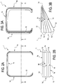
- Figure 3A shows a front view of the connection device 1 when the units 3 coupled to the device 1 are misaligned
- Figure 3B shows a top view of the connection device 1 along the section C-C shown in Figure 3A
- the tubular elements 10 of the connection device 1 are configured to be compressed, in particular at one or both of the side walls 1d, 1e, when the two units 3 of the articulated bus 2 are misaligned, for example on a bend.
- the passages 14 may be positioned alternately at the opposite ends of a length of the tubular elements 10 for pairs of adjacent tubular elements 10.
- the passages 14 may be positioned alternately at the opposite ends of a length of the tubular elements 10 for pairs of adjacent tubular elements 10.
- Figure 4 shows a top view of the connection device 1 according to one or more embodiments, wherein the same references used for the previous drawings indicate the same elements having the same technical/functional features.
- the passages 14 may be located at opposite ends of the upper wall 1c.
- FIG. 5 shows a top view of the connection device 1 according to one or more embodiments, wherein the same references used for the previous drawings indicate the same elements having the same technical/functional features.
- each of the tubular elements 10 may be isolated from the other tubular elements 10 (that is, it does not comprise any passage 14) and may comprise a respective opening 12.
- each of the tubular elements 10 may be independently inflated and be watertight relative to the adjacent tubular elements 10.
- the fluid escapes only from the broken tubular element 10, without resulting in the total deflation of the structure.
- the openings 12 may be located in a lower portion of the tubular elements 10, for example in a portion in contact with the connecting and articulated joint of the bus 2.
- the one or more openings 12 of the connection device 1 may be coupled directly or indirectly to a source of fluid 16 which generates pressurised fluid, for example a fan and/or a compressor, configured for introducing fluid inside the plurality of tubular elements 10.
- a source of fluid 16 which generates pressurised fluid
- a fan and/or a compressor configured for introducing fluid inside the plurality of tubular elements 10.
- the pressure inside the tubular elements may be between 0.01 MPa and 0.2 MPa, preferably between 0.02 MPa and 0.15 MPa, more preferably between 0.04 MPa and 0.1 MPa.
- the operating pressure may be defined as a function of the source of fluid 16 selected.
- the opening 12 of a connection device 1 as described with reference to any one of the preceding drawings may be coupled to the source of fluid 16 by means of a valve 17, configured to allow the transfer of fluid from or to the plurality of tubular elements 10 when open.
- the valve 17 may be open for introducing and/or extracting fluid, whilst it may remain closed otherwise.
- the valve 17 may be coupled to the source of fluid 16 and open during the inflation of the tubular elements 10 and may be uncoupled and closed once the tubular elements 10 are inflated, so that the structure formed by the plurality of tubular elements 10 becomes sealed (when the tubular elements 10 are not inflated).
- the open valve 17 may be coupled, directly or indirectly, to the source of fluid 16 during inflation of the tubular elements 10.
- valve 17 may be coupled to an inflatable relief element, for example a balloon.
- the coupling between the valve 17 and the inflatable relief element allows the tunnel-like structure of the sealed connection device 1 to be maintained when the tubular elements 10 are not inflated.
- the fluid may escape from the tubular elements 10, for example through the opening 12.
- the relief element initially deflated
- the relief element may receive fluid when necessary, for example when the tubular elements 10 are compressed and the pressure of the fluid inside them increases.
- the source of pressurised fluid 16 may, in use, remain coupled, directly or indirectly, for example by means of the valve 17, to the one or more openings 12.
- the source of fluid 16 may be configured to adjust a flow of fluid as a function of a pressure inside the plurality of tubular elements 10, so as to maintain a predetermined pressure, for example a constant pressure, inside the self-supporting structure comprising the plurality of tubular elements 10.
- the fluid may escape from the tubular elements 10, for example through the opening 12.
- the source of fluid 16 may be configured for extracting and/or introducing fluid, for example air, from or in the opening 12, with a quantity such as to maintain a predetermined pressure, for example constant, inside the tubular elements 10, so as to compensate for the compression of the tubular elements 10 following relative movements of the units 3.
- one or more or all of the tubular elements 10 may comprise a plurality of micro-holes 18.
- the micro-holes 18 may be positioned at the side walls 1d, 1e and/or at the upper wall 1c, towards the inside of the articulated bus 2, that is, towards an inner portion 1f of the tunnel structure of the connection device 1.
- the plurality of micro-holes 18 may be configured for transferring the fluid from the one or more or all the tubular elements 10 towards the inner portion 1f of the tunnel structure of the connection device 1.
- the micro-holes 18 may be between 0.1 mm and 5 mm, preferably between 0.2 mm and 2.5 mm, more preferably between 0.4 mm and 1.5 mm, even more preferably between 0.8 mm and 1.2 mm.
- the source of fluid 16 may be configured to keep a predetermined pressure compensating both the compression of the tubular elements 10 following relative movements of the units 3 and the escape of fluid through the micro-holes 18.
- the operating pressure may be defined as a function of the source of fluid 16 selected and of the size of the micro-holes 18.
- the presence of micro-holes 18 makes it possible to extract fluid from the tubular elements 10 and insert it inside the articulated bus 2.
- the source of fluid 16 may be configured for sucking air from the inside of one or both the units 3 of the articulated bus 2, and introducing the sucked air inside the tubular elements 10.
- the air which passes through the micro-holes 18 is approximately at the same temperature as the air inside the units 3 of the articulated bus 2.
- one or more embodiments may relate to a system 4 for connecting and closing mountable on an articulated bus and treatment of the air between the two units 3 of an articulated vehicle 2.
- the connecting and closing system 4 comprises a connection device 1 as described with reference to Figure 8 , that is to say, comprising a plurality of micro-holes 18 in one, more or all the tubular elements 10 towards the inner portion 1f of the tunnel structure formed by the plurality of tubular elements 10.
- the connecting and closing system 4 comprises a thermal treatment system 20, coupled directly or indirectly to the one or more openings 12 and configured for thermally treating the fluid comprising air inserted inside the plurality of tubular elements 10, for example for heating or cooling the air in the plurality of tubular elements 10.
- the thermal treatment plant 4 may be coupled to the opening 12 on a same line with respect to the source of fluid 16.
- the thermal treatment plant 20 is illustrated downstream of the source of pressurised fluid 16, however it is possible to locate it upstream, or on a line for connection to the opening 12 alternative to that of the source of pressurised fluid 16.
- the thermal treatment plant 20 may comprise a heat exchanger 22, configured for cooling and/or heating the fluid, for example the air inside the plurality of tubular elements 10.
- a heat exchanger 22 configured for cooling and/or heating the fluid, for example the air inside the plurality of tubular elements 10.
- the air which escapes from the plurality of micro-holes 18 towards the inside of the connecting portion 1f between the two units 3 of the articulated bus 2 can be conditioned.
- the presence of micro-holes 18 may allow hot or cold air to be introduced, depending on the season, in the connecting portion between the units 3 of the bus 2, which conventionally is colder or hotter than the rest of the bus 2.
- the heat exchanger 20 may be located close to the engine (not illustrated) of the bus 2 and may be configured to use the heat generated by the engine of the bus 2 for heating the fluid inside the plurality of tubular elements 10.
- One or more embodiments relate to a method for operating a device 1 for connecting and closing the space between two units 3 of an articulated vehicle 2.
- the method comprises:
- the method can comprise the step of adjusting a flow of fluid as a function of a pressure inside the plurality of tubular elements 10, so as to maintain a predetermined pressure, for example constant, inside the plurality of tubular elements 10.
- the method can comprise the steps of:
- the method may comprise the step of maintaining the tunnel structure of the connection device 1 in a sealed fashion, when the tubular elements 10 are not inflated.
Landscapes
- Engineering & Computer Science (AREA)
- Mechanical Engineering (AREA)
- Chemical & Material Sciences (AREA)
- Combustion & Propulsion (AREA)
- Transportation (AREA)
- Life Sciences & Earth Sciences (AREA)
- Wood Science & Technology (AREA)
- Air-Conditioning For Vehicles (AREA)
- Forklifts And Lifting Vehicles (AREA)
- Lock And Its Accessories (AREA)
- Quick-Acting Or Multi-Walled Pipe Joints (AREA)
Abstract
Description
- This invention relates to a device for connecting and closing articulated road vehicles, for example articulated buses, trams, or vehicles designed to circulate on rails.
- With reference, as a non-limiting example, to an articulated bus, it is known that between the two carriages of the bus there is a rotatable platform (known as "rack'), the purpose of which is also that of allowing both the passage and the standing of passengers in the connecting zone between the carriages. The connecting zone must inevitably guarantee safe conditions even when the bus goes round a bend, that is to say, even when the two carriages are not aligned with each other allowing a tunnel-like free passage.
- For that purpose, the connecting zone is closed inside a connecting and closing device shaped to define a tunnel for passage between the two carriages, to which it is connected.
- More specifically, the ends of the connection device are connected to the free ends of the two carriages, in such a way that the device deforms when the bus adopts configurations wherein the two carriages are not are aligned with each other.
- The conventional connection devices comprise a supporting structure which increases the weight of the connection device, and this results in, in use, an additional energy consumption of the vehicle as well as a reduction of the useful life of the shock absorbing system of the vehicle.
- One aim of this invention, therefore, is to provide a connecting and closing device for carriages of articulated vehicles, in particular articulated buses, which is lightweight and ensures the necessary functionality.
- A further aim of this invention is to provide a connection device which is particularly simple, practical and flexible, so as to be able to adapt to the various needs during use of the vehicle, for example along a bend in the case of relative movements, even significant, between the two units.
- The technical characteristics of the invention, with reference to the above aims, are clearly described in the claims below and its advantages are apparent from the detailed description which follows, with reference to the accompanying drawings which illustrate a preferred embodiments of the invention provided merely by way of example without restricting the scope of the inventive concept, and in which:
-
Figure 1 shows an articulated vehicle, in particular a bus, equipped with a connecting and closing device in accordance with the invention; -
Figures 2A and 2B are a front view and a top view of a connection device according to the invention, -
Figures 3A and 3B are a front view and a top view of a connection device according to the invention, -
Figures 4 to 7 illustrate aspects of connection devices according to one or more embodiments of the invention, and -
Figure 8 shows a system for connecting and closing and thermal treatment according to the invention. - In this invention, reference will be made for simplicity to a device designed for installation between carriages of an articulated bus, however this solution may be applied to any type of articulated vehicle.
- In effect, the invention can be applied, for example, to articulated buses, trams or vehicles designed to circulate on rails.
- All the embodiments described with reference to a connection of articulated bus carriages are provided purely by way of non-limiting example.
-
Figure 1 illustrates aconnection device 1 according to one or more embodiments mounted on an articulatedbus 2 comprising twounits 3. Theconnection device 1 may be mounted on thebus 2 for joining together the rooms of the two adjacent units (or carriages) 3. The articulatedbus 2 also comprises a connecting and articulated joint interposed between the units to allow the relative movement, such that theconnection device 1 is able to close the space between the twounits 3 at the connecting joint. - The
connection device 1 is located at an articulated joint (not illustrated inFigure 1 ) for connecting between the twocarriages 3 which allows the relative movement. The passage of the passengers is generally allowed at the articulated jointing the connecting zone between the carriages orunit 3. - The
connection device 1 comprises a plurality of inflatabletubular elements 10 made of flexible material, for example PVC, polyvinyl chloride and, more generally, elastomers. The flexible materials may comprise materials used for making tyres, for example rubber mixes, if necessary with structural stabilising elements. Thetubular elements 10 are located alongside one another, for example eachtubular element 10 may be joined to the one or more immediately adjacenttubular elements 10. The plurality oftubular elements 10 forms a tunnel-like structure for passage and connection between the twocarriages 3. - In particular, a first and a
second end free ends carriages 3, in such a way that theconnection device 1 deforms when thebus 2 adopts configurations wherein the twocarriages 3 are not aligned with each other, as occurs, for example, along bends during normal travel. The tunnel structure of theconnection device 1 has anupper wall 1c and a first andsecond side wall upper wall 1c andside walls second ends connection device 1. - According to one or more embodiments,
Figure 2A shows a front view of theconnection device 1 andFigure 2B shows a top view of theconnection device 1 along the section B-B shown inFigure 2A . - One or more of the
tubular elements 10 may comprise one ormore openings 12 configured for introducing fluid, preferably a gas, even more preferably air, inside the one or moretubular elements 10. For example, thetubular element 10 at one of the twoends tubular elements 10 may comprise the at least oneopening 12. As illustrated inFigures 2A, 2B , both of thetubular elements 10 at the opposite ends of the tunnel structure, that is to say, thetubular elements 10 at theends connection device 1, may comprise arespective opening 12. For example, the one ormore openings 12 may be on frames of theconnection device 1 at theends - According to one or more embodiments, by means of the one or
more openings 12, thetubular elements 10 can be inflated and, once inflated, the tunnel structure is substantially self-supporting. In other words, once inflated, the structure formed by the plurality oftubular elements 10 is able to connect theunits 3 of the articulated bus even when these units are misaligned and at the same time it is able to support itself, that is to say, without using supporting structures. - According to one or more embodiments, there may be further openings or
passages 14 at each point of contact between pairs of adjacenttubular elements 10, with thepassages 14 configured to allow the passage of fluid between thetubular elements 10 in the pair. In this way, even if only one or both of thetubular elements 10 at theends opening 12, thetubular elements 10 which do not comprise anopening 12 can also be inflated. - Each
passage 14 may be formed at any point of a contact area between onetubular element 10 and the adjacent one in the pair oftubular elements 10. For each pair of adjacenttubular elements 10, the contact area may comprise one ormore passages 14. - For example, but without limiting the scope of the invention, as illustrated in
Figure 2B , thepassages 14 may be located on the contact area at theupper wall 1c of theconnection element 1. Again for example, thepassages 14 may be located, for each pair of adjacenttubular elements 10, at a same point along the length of thetubular elements 10. - According to one or more embodiments,
Figure 3A shows a front view of theconnection device 1 when theunits 3 coupled to thedevice 1 are misaligned, andFigure 3B shows a top view of theconnection device 1 along the section C-C shown inFigure 3A . Thetubular elements 10 of theconnection device 1 are configured to be compressed, in particular at one or both of theside walls units 3 of the articulatedbus 2 are misaligned, for example on a bend. - As may be seen in
Figure 3B , relative to the situation wherein twounits 3 of the articulatedbus 2 are misaligned, for example along a bend, when portions of thetubular elements 10 at thesecond side wall 1e are compressed, portions of thetubular elements 10 at thefirst side wall 1d are stretched, as a result of an increased pressure inside thetubular elements 10. In this way, when one or moretubular elements 10 are compressed, the fluid contained inside them, subjected to a greater pressure, may be divided along a length of thetubular elements 10. - According to one or more embodiments, the
passages 14 may be positioned alternately at the opposite ends of a length of thetubular elements 10 for pairs of adjacenttubular elements 10. Advantageously, in this way almost the integrity of atubular element 10 can be inflated before the fluid starts to flow in the nexttubular element 10. -
Figure 4 shows a top view of theconnection device 1 according to one or more embodiments, wherein the same references used for the previous drawings indicate the same elements having the same technical/functional features. InFigure 4 , thepassages 14 may be located at opposite ends of theupper wall 1c. -
Figure 5 shows a top view of theconnection device 1 according to one or more embodiments, wherein the same references used for the previous drawings indicate the same elements having the same technical/functional features. InFigure 5 , each of thetubular elements 10 may be isolated from the other tubular elements 10 (that is, it does not comprise any passage 14) and may comprise arespective opening 12. In other words, each of thetubular elements 10 may be independently inflated and be watertight relative to the adjacenttubular elements 10. Advantageously, in this way, if a twist is formed in atubular element 10 in the structure, the fluid escapes only from the brokentubular element 10, without resulting in the total deflation of the structure. - The
openings 12 may be located in a lower portion of thetubular elements 10, for example in a portion in contact with the connecting and articulated joint of thebus 2. - As illustrated in
Figure 6 , the one ormore openings 12 of theconnection device 1, as described with reference to any one of the preceding drawings, may be coupled directly or indirectly to a source offluid 16 which generates pressurised fluid, for example a fan and/or a compressor, configured for introducing fluid inside the plurality oftubular elements 10. - The pressure inside the tubular elements (differential relative to that of the outside environment) may be between 0.01 MPa and 0.2 MPa, preferably between 0.02 MPa and 0.15 MPa, more preferably between 0.04 MPa and 0.1 MPa. The operating pressure may be defined as a function of the source of
fluid 16 selected. - As illustrated in
Figure 7 , theopening 12 of aconnection device 1 as described with reference to any one of the preceding drawings may be coupled to the source offluid 16 by means of a valve 17, configured to allow the transfer of fluid from or to the plurality oftubular elements 10 when open. In other words, the valve 17 may be open for introducing and/or extracting fluid, whilst it may remain closed otherwise. - According to one or more embodiments, the valve 17 may be coupled to the source of
fluid 16 and open during the inflation of thetubular elements 10 and may be uncoupled and closed once thetubular elements 10 are inflated, so that the structure formed by the plurality oftubular elements 10 becomes sealed (when thetubular elements 10 are not inflated). - According to one or more embodiments, the open valve 17 may be coupled, directly or indirectly, to the source of
fluid 16 during inflation of thetubular elements 10. - According to another aspect, the valve 17 may be coupled to an inflatable relief element, for example a balloon.
- In this way, the coupling between the valve 17 and the inflatable relief element allows the tunnel-like structure of the sealed
connection device 1 to be maintained when thetubular elements 10 are not inflated. When one or more portions of thetubular elements 10 are compressed, the fluid may escape from thetubular elements 10, for example through theopening 12. For this reason, the relief element (initially deflated) may receive fluid when necessary, for example when thetubular elements 10 are compressed and the pressure of the fluid inside them increases. - According to one or more embodiments, the source of pressurised
fluid 16 may, in use, remain coupled, directly or indirectly, for example by means of the valve 17, to the one ormore openings 12. The source offluid 16 may be configured to adjust a flow of fluid as a function of a pressure inside the plurality oftubular elements 10, so as to maintain a predetermined pressure, for example a constant pressure, inside the self-supporting structure comprising the plurality oftubular elements 10. - When one or more portions of the
tubular elements 10 are compressed, the fluid may escape from thetubular elements 10, for example through theopening 12. In this case, the source offluid 16 may be configured for extracting and/or introducing fluid, for example air, from or in theopening 12, with a quantity such as to maintain a predetermined pressure, for example constant, inside thetubular elements 10, so as to compensate for the compression of thetubular elements 10 following relative movements of theunits 3. - According to one or more embodiments, when the source of
fluid 16 remains coupled, in use, to the one ormore openings 12, one or more or all of thetubular elements 10 may comprise a plurality ofmicro-holes 18. - As illustrated in
Figure 8 , the micro-holes 18 may be positioned at theside walls upper wall 1c, towards the inside of the articulatedbus 2, that is, towards aninner portion 1f of the tunnel structure of theconnection device 1. The plurality ofmicro-holes 18 may be configured for transferring the fluid from the one or more or all thetubular elements 10 towards theinner portion 1f of the tunnel structure of theconnection device 1. The micro-holes 18 may be between 0.1 mm and 5 mm, preferably between 0.2 mm and 2.5 mm, more preferably between 0.4 mm and 1.5 mm, even more preferably between 0.8 mm and 1.2 mm. - In this case, the source of
fluid 16 may be configured to keep a predetermined pressure compensating both the compression of thetubular elements 10 following relative movements of theunits 3 and the escape of fluid through the micro-holes 18. The operating pressure may be defined as a function of the source offluid 16 selected and of the size of the micro-holes 18. Advantageously, the presence ofmicro-holes 18 makes it possible to extract fluid from thetubular elements 10 and insert it inside the articulatedbus 2. - According to one or more embodiments, the source of
fluid 16 may be configured for sucking air from the inside of one or both theunits 3 of the articulatedbus 2, and introducing the sucked air inside thetubular elements 10. Advantageously, in this way the air which passes through the micro-holes 18 is approximately at the same temperature as the air inside theunits 3 of the articulatedbus 2. - As illustrated in
Figure 8 , one or more embodiments may relate to a system 4 for connecting and closing mountable on an articulated bus and treatment of the air between the twounits 3 of an articulatedvehicle 2. The connecting and closing system 4 comprises aconnection device 1 as described with reference toFigure 8 , that is to say, comprising a plurality ofmicro-holes 18 in one, more or all thetubular elements 10 towards theinner portion 1f of the tunnel structure formed by the plurality oftubular elements 10. - The connecting and closing system 4 comprises a
thermal treatment system 20, coupled directly or indirectly to the one ormore openings 12 and configured for thermally treating the fluid comprising air inserted inside the plurality oftubular elements 10, for example for heating or cooling the air in the plurality oftubular elements 10. - As illustrated in
Figure 8 , the thermal treatment plant 4 may be coupled to theopening 12 on a same line with respect to the source offluid 16. For example, thethermal treatment plant 20 is illustrated downstream of the source of pressurisedfluid 16, however it is possible to locate it upstream, or on a line for connection to theopening 12 alternative to that of the source of pressurisedfluid 16. - The
thermal treatment plant 20 may comprise aheat exchanger 22, configured for cooling and/or heating the fluid, for example the air inside the plurality oftubular elements 10. In this way, the air which escapes from the plurality ofmicro-holes 18 towards the inside of the connectingportion 1f between the twounits 3 of the articulatedbus 2 can be conditioned. Advantageously, the presence ofmicro-holes 18 may allow hot or cold air to be introduced, depending on the season, in the connecting portion between theunits 3 of thebus 2, which conventionally is colder or hotter than the rest of thebus 2. - According to one or more embodiments, the
heat exchanger 20 may be located close to the engine (not illustrated) of thebus 2 and may be configured to use the heat generated by the engine of thebus 2 for heating the fluid inside the plurality oftubular elements 10. - One or more embodiments relate to a method for operating a
device 1 for connecting and closing the space between twounits 3 of an articulatedvehicle 2. The method comprises: - preparing a
connection device 1 according to one or more embodiments, - preparing a
source 16 which generates pressurised fluid, - inflating the plurality of
tubular elements 10 of theconnection device 1 using the one ormore openings 12. - The method can comprise the step of adjusting a flow of fluid as a function of a pressure inside the plurality of
tubular elements 10, so as to maintain a predetermined pressure, for example constant, inside the plurality oftubular elements 10. - The method can comprise the steps of:
- preparing a plurality of
micro-holes 18 in one, more or all thetubular elements 10, positioned towards aninner portion 1f of the tunnel structure of theconnection device 1, and - transferring the fluid from the
tubular elements 10 comprising the micro-holes 18 towards theinner portion 1f of the tunnel structure of theconnection device 1 using the micro-holes 18. - The method may comprise the step of maintaining the tunnel structure of the
connection device 1 in a sealed fashion, when thetubular elements 10 are not inflated.
Claims (17)
- A device (1) for connecting and closing the space between two units (3) of an articulated vehicle (2), comprising:- a plurality of inflatable tubular elements (10) which are made of flexible material, the tubular elements (10) in the plurality of tubular elements (10) positioned one alongside the other and forming a tunnel structure having an upper wall (1c) and two side walls (1d, 1e), the structure having two ends (1a, 1b) which can be coupled to respective ends (3a, 3b) of said two units (3) of the articulated vehicle (2),- at least one opening (12) for introducing fluid inside at least one tubular element (10) in the plurality of tubular elements (10),wherein the structure formed by the plurality of tubular elements (10), when inflated, is substantially self-supporting.
- The connection device according to claim 1, wherein at least one tubular element (10) at one of said two ends (1a, 1b) of the structure formed by the plurality of tubular elements (10) comprises the at least one opening (12).
- The connection device according to claim 1 or 2, wherein the tubular elements (10) are configured to be compressed, preferably at one or both of the two side walls (1d, 1e).
- The connection device according to any one of the preceding claims, wherein, at each point of contact between pairs of adjacent tubular properties (10), there is at least one further opening (14) to allow the passage of fluid between the tubular elements (10) in the pair.
- The connection device according to any one of claims 1 to 3, wherein each tubular element (10) in the plurality of tubular elements (10):- is isolated from the other tubular elements (10) in the plurality of tubular elements (10), and- comprises a respective opening (12).
- The connection device according to any one of the preceding claims, wherein the at least one opening (12) can be coupled to a source (16) which generates pressurised fluid and is configured to introduce fluid into the plurality of tubular elements (10).
- The connection device according to any one of the preceding claims, wherein the tunnel structure is configured to be closed in a watertight fashion.
- The connection device according to claim 6, wherein the source (16) of pressurised fluid is coupled in use to the at least one opening (12) and is configured for adjusting a flow of fluid as a function of a pressure inside the plurality of tubular elements (10), so as to maintain a predetermined pressure inside said plurality of tubular elements (10).
- The connection device according to claim 8, wherein at least one tubular element (10) in the plurality of tubular elements (10) comprises a plurality of micro-holes (18), positioned towards an inner portion of the tunnel structure of the connection device (1) and configured for transferring the fluid from said at least one tubular element (10) towards said inner portion of the tunnel structure of the connection device (1).
- A system (1) for connecting and closing and thermal treatment of the space between two units (3) of an articulated vehicle (2), comprising:- a connection and closing device according to claim 8,- a thermal treatment plant configured for thermally treating the fluid, comprising air, inserted inside the plurality of tubular elements 10.
- The system (1) for connection and closing and treating the air according to claim 10, wherein the thermal treatment plant (20) comprises a heat exchanger (22), configured to cool and/or heat the fluid comprising air inside the plurality of tubular elements (10).
- An articulated vehicle (2), comprising:- at least two units (3);- a connecting joint and junction interposed between the units to allow the relative movement; and- a connection device (1) according to any one of claims 1 to 9, configured to close the space between the two units (3) at said connecting joint.
- The articulated vehicle (2) according to claim 12, comprising:- a connection device (1) according to claim 9, and- a thermal treatment plant (20) according to claim 10 or 11.
- A method for operating a device for connecting and closing the space between two units (3) of an articulated vehicle (2), the process comprising:- preparing a connection device (1) according to any one of claims 1 to 9,- preparing a source (16) which generates pressurised fluid,- inflating the plurality of tubular elements (10) of said connection device (1) by means of the at least one opening (12).
- The method according to claim 14, comprising a step of adjusting a flow of fluid as a function of a pressure inside the plurality of tubular elements (10), so as to maintain a predetermined pressure inside said plurality of tubular elements (10).
- The method according to claim 15, comprising the steps of:- preparing a plurality of micro-holes (18) in at least one tubular element (10) in the plurality of tubular elements (10), positioned towards an inner portion (1f) of the tunnel structure of the connection device (1), and- transferring the fluid from said at least one tubular element (10) towards said inner portion (1f) of the tunnel structure of the connection device (1) by means of said plurality of micro-holes (18).
- The method according to claim 14, comprising the step of closing the tunnel structure of the connection device (1) in a watertight fashion.
Priority Applications (1)
| Application Number | Priority Date | Filing Date | Title |
|---|---|---|---|
| PL20180340T PL3753759T3 (en) | 2019-06-21 | 2020-06-16 | Connecting and closing device for articulated vehicle, corresponding articulated vehicle and method |
Applications Claiming Priority (1)
| Application Number | Priority Date | Filing Date | Title |
|---|---|---|---|
| IT102019000009846A IT201900009846A1 (en) | 2019-06-21 | 2019-06-21 | CONNECTION AND LOCKING DEVICE FOR ARTICULATED VEHICLE, CORRESPONDING ARTICULATED VEHICLE AND PROCEDURE. |
Publications (2)
| Publication Number | Publication Date |
|---|---|
| EP3753759A1 true EP3753759A1 (en) | 2020-12-23 |
| EP3753759B1 EP3753759B1 (en) | 2022-03-30 |
Family
ID=68234262
Family Applications (1)
| Application Number | Title | Priority Date | Filing Date |
|---|---|---|---|
| EP20180340.0A Active EP3753759B1 (en) | 2019-06-21 | 2020-06-16 | Connecting and closing device for articulated vehicle, corresponding articulated vehicle and method |
Country Status (3)
| Country | Link |
|---|---|
| EP (1) | EP3753759B1 (en) |
| IT (1) | IT201900009846A1 (en) |
| PL (1) | PL3753759T3 (en) |
Cited By (2)
| Publication number | Priority date | Publication date | Assignee | Title |
|---|---|---|---|---|
| CN112550327A (en) * | 2020-12-25 | 2021-03-26 | 常州今创风挡系统有限公司 | Inflatable outer windshield |
| CN112606858A (en) * | 2020-12-25 | 2021-04-06 | 常州今创风挡系统有限公司 | Outer windshield |
Citations (5)
| Publication number | Priority date | Publication date | Assignee | Title |
|---|---|---|---|---|
| DE939817C (en) * | 1953-09-24 | 1956-03-01 | Alweg Forschung | Elastic bellows connection, especially for vehicles |
| EP0067944A2 (en) * | 1981-06-24 | 1982-12-29 | Messerschmitt-Bölkow-Blohm Gesellschaft mit beschränkter Haftung | Coach communication passage for high speed rail vehicles |
| DE4104239A1 (en) * | 1990-11-12 | 1992-05-14 | Huebner Gummi & Kunststoff | Folding passageway between two carriages of high speed train - makes use of interpositioned hoses inflatable according to travelling speed |
| DE19802123A1 (en) * | 1997-01-22 | 1998-07-23 | Jenbacher Energiesysteme Ag | Flexible bellows connection for railway carriages |
| DE102017121325A1 (en) * | 2017-09-14 | 2019-03-14 | HÜBNER GmbH & Co. KG | articulated vehicle |
-
2019
- 2019-06-21 IT IT102019000009846A patent/IT201900009846A1/en unknown
-
2020
- 2020-06-16 EP EP20180340.0A patent/EP3753759B1/en active Active
- 2020-06-16 PL PL20180340T patent/PL3753759T3/en unknown
Patent Citations (5)
| Publication number | Priority date | Publication date | Assignee | Title |
|---|---|---|---|---|
| DE939817C (en) * | 1953-09-24 | 1956-03-01 | Alweg Forschung | Elastic bellows connection, especially for vehicles |
| EP0067944A2 (en) * | 1981-06-24 | 1982-12-29 | Messerschmitt-Bölkow-Blohm Gesellschaft mit beschränkter Haftung | Coach communication passage for high speed rail vehicles |
| DE4104239A1 (en) * | 1990-11-12 | 1992-05-14 | Huebner Gummi & Kunststoff | Folding passageway between two carriages of high speed train - makes use of interpositioned hoses inflatable according to travelling speed |
| DE19802123A1 (en) * | 1997-01-22 | 1998-07-23 | Jenbacher Energiesysteme Ag | Flexible bellows connection for railway carriages |
| DE102017121325A1 (en) * | 2017-09-14 | 2019-03-14 | HÜBNER GmbH & Co. KG | articulated vehicle |
Cited By (4)
| Publication number | Priority date | Publication date | Assignee | Title |
|---|---|---|---|---|
| CN112550327A (en) * | 2020-12-25 | 2021-03-26 | 常州今创风挡系统有限公司 | Inflatable outer windshield |
| CN112606858A (en) * | 2020-12-25 | 2021-04-06 | 常州今创风挡系统有限公司 | Outer windshield |
| CN112606858B (en) * | 2020-12-25 | 2024-07-30 | 常州今创风挡系统有限公司 | Outer windshield |
| CN112550327B (en) * | 2020-12-25 | 2025-01-14 | 常州今创风挡系统有限公司 | Inflatable outer windshield |
Also Published As
| Publication number | Publication date |
|---|---|
| PL3753759T3 (en) | 2022-06-06 |
| BR102020012439A2 (en) | 2021-08-17 |
| IT201900009846A1 (en) | 2020-12-21 |
| EP3753759B1 (en) | 2022-03-30 |
Similar Documents
| Publication | Publication Date | Title |
|---|---|---|
| EP3753759B1 (en) | Connecting and closing device for articulated vehicle, corresponding articulated vehicle and method | |
| US10792962B2 (en) | All-terrain vehicle and its suspension | |
| CN107097623A (en) | Inflatable door seal | |
| EP1703814B1 (en) | Conditioning garments | |
| CN109159790B (en) | Automatic inflation and deflation outer windshield and motor train unit | |
| CN108146185B (en) | Defrosting control device, air conditioner and defrosting control method of air conditioner | |
| BR112018068067B1 (en) | Valve assembly, hubcap and automatic tire inflation system | |
| KR102061365B1 (en) | Device for maintaining and changing the pressure in tyres | |
| RU205744U1 (en) | MOBILE PNEUMATIC FRAME MODULE | |
| BR102020012439B1 (en) | CONNECTION AND CLOSING DEVICE FOR ARTICULATED VEHICLE, CORRESPONDING ARTICULATED VEHICLE AND METHOD | |
| CN103231628B (en) | Vacuum tyre tire-burst safety device | |
| CN209600205U (en) | A kind of dedicated armoring air-conditioning device of panzer | |
| CN117445959A (en) | Inflatable outer windshield, rail vehicle and control method | |
| EP3612446A1 (en) | Aircraft auxiliary power unit exhaust pipe seals and methods | |
| US1464085A (en) | Pneumatic tire | |
| CN207565268U (en) | Defrosting control device and air conditioner | |
| CN121129520A (en) | A positional adjustment device for epilepsy patients and its usage method | |
| CN214088273U (en) | Uniform heating device for glass tempering production | |
| DE602005004667D1 (en) | System for air conditioning an environment, in particular the passenger compartment of a motor vehicle | |
| CN219589139U (en) | Energy-saving device of air conditioning unit | |
| CN220238592U (en) | Adsorbent activation device | |
| CN210132988U (en) | Inflatable door seal for loading and unloading goods of warehouse truck | |
| ITGE960046A1 (en) | HEATING OR COOLING SYSTEM FOR SEATS PREFERABLY OF MOTOR VEHICLES. | |
| BR112021013540A2 (en) | ROUGH-COOLING ARRANGEMENT FOR ROUGH-COOLING GLASS SHEETS, AND METHOD FOR ROUGH-COOLING GLASS SHEETS FORMED IN A ROUGH-COOLING ARRANGEMENT | |
| OA18181A (en) | All-terrain vehicle and suspension for an allrerrain vehicle |
Legal Events
| Date | Code | Title | Description |
|---|---|---|---|
| PUAI | Public reference made under article 153(3) epc to a published international application that has entered the european phase |
Free format text: ORIGINAL CODE: 0009012 |
|
| STAA | Information on the status of an ep patent application or granted ep patent |
Free format text: STATUS: THE APPLICATION HAS BEEN PUBLISHED |
|
| AK | Designated contracting states |
Kind code of ref document: A1 Designated state(s): AL AT BE BG CH CY CZ DE DK EE ES FI FR GB GR HR HU IE IS IT LI LT LU LV MC MK MT NL NO PL PT RO RS SE SI SK SM TR |
|
| AX | Request for extension of the european patent |
Extension state: BA ME |
|
| STAA | Information on the status of an ep patent application or granted ep patent |
Free format text: STATUS: REQUEST FOR EXAMINATION WAS MADE |
|
| 17P | Request for examination filed |
Effective date: 20210618 |
|
| RBV | Designated contracting states (corrected) |
Designated state(s): AL AT BE BG CH CY CZ DE DK EE ES FI FR GB GR HR HU IE IS IT LI LT LU LV MC MK MT NL NO PL PT RO RS SE SI SK SM TR |
|
| GRAP | Despatch of communication of intention to grant a patent |
Free format text: ORIGINAL CODE: EPIDOSNIGR1 |
|
| STAA | Information on the status of an ep patent application or granted ep patent |
Free format text: STATUS: GRANT OF PATENT IS INTENDED |
|
| INTG | Intention to grant announced |
Effective date: 20211027 |
|
| GRAS | Grant fee paid |
Free format text: ORIGINAL CODE: EPIDOSNIGR3 |
|
| GRAA | (expected) grant |
Free format text: ORIGINAL CODE: 0009210 |
|
| STAA | Information on the status of an ep patent application or granted ep patent |
Free format text: STATUS: THE PATENT HAS BEEN GRANTED |
|
| AK | Designated contracting states |
Kind code of ref document: B1 Designated state(s): AL AT BE BG CH CY CZ DE DK EE ES FI FR GB GR HR HU IE IS IT LI LT LU LV MC MK MT NL NO PL PT RO RS SE SI SK SM TR |
|
| REG | Reference to a national code |
Ref country code: GB Ref legal event code: FG4D |
|
| REG | Reference to a national code |
Ref country code: CH Ref legal event code: EP |
|
| REG | Reference to a national code |
Ref country code: AT Ref legal event code: REF Ref document number: 1478854 Country of ref document: AT Kind code of ref document: T Effective date: 20220415 |
|
| REG | Reference to a national code |
Ref country code: DE Ref legal event code: R096 Ref document number: 602020002412 Country of ref document: DE |
|
| REG | Reference to a national code |
Ref country code: IE Ref legal event code: FG4D |
|
| REG | Reference to a national code |
Ref country code: LT Ref legal event code: MG9D |
|
| PG25 | Lapsed in a contracting state [announced via postgrant information from national office to epo] |
Ref country code: SE Free format text: LAPSE BECAUSE OF FAILURE TO SUBMIT A TRANSLATION OF THE DESCRIPTION OR TO PAY THE FEE WITHIN THE PRESCRIBED TIME-LIMIT Effective date: 20220330 Ref country code: RS Free format text: LAPSE BECAUSE OF FAILURE TO SUBMIT A TRANSLATION OF THE DESCRIPTION OR TO PAY THE FEE WITHIN THE PRESCRIBED TIME-LIMIT Effective date: 20220330 Ref country code: NO Free format text: LAPSE BECAUSE OF FAILURE TO SUBMIT A TRANSLATION OF THE DESCRIPTION OR TO PAY THE FEE WITHIN THE PRESCRIBED TIME-LIMIT Effective date: 20220630 Ref country code: LT Free format text: LAPSE BECAUSE OF FAILURE TO SUBMIT A TRANSLATION OF THE DESCRIPTION OR TO PAY THE FEE WITHIN THE PRESCRIBED TIME-LIMIT Effective date: 20220330 Ref country code: HR Free format text: LAPSE BECAUSE OF FAILURE TO SUBMIT A TRANSLATION OF THE DESCRIPTION OR TO PAY THE FEE WITHIN THE PRESCRIBED TIME-LIMIT Effective date: 20220330 Ref country code: BG Free format text: LAPSE BECAUSE OF FAILURE TO SUBMIT A TRANSLATION OF THE DESCRIPTION OR TO PAY THE FEE WITHIN THE PRESCRIBED TIME-LIMIT Effective date: 20220630 |
|
| REG | Reference to a national code |
Ref country code: NL Ref legal event code: MP Effective date: 20220330 |
|
| REG | Reference to a national code |
Ref country code: AT Ref legal event code: MK05 Ref document number: 1478854 Country of ref document: AT Kind code of ref document: T Effective date: 20220330 |
|
| PG25 | Lapsed in a contracting state [announced via postgrant information from national office to epo] |
Ref country code: LV Free format text: LAPSE BECAUSE OF FAILURE TO SUBMIT A TRANSLATION OF THE DESCRIPTION OR TO PAY THE FEE WITHIN THE PRESCRIBED TIME-LIMIT Effective date: 20220330 Ref country code: GR Free format text: LAPSE BECAUSE OF FAILURE TO SUBMIT A TRANSLATION OF THE DESCRIPTION OR TO PAY THE FEE WITHIN THE PRESCRIBED TIME-LIMIT Effective date: 20220701 Ref country code: FI Free format text: LAPSE BECAUSE OF FAILURE TO SUBMIT A TRANSLATION OF THE DESCRIPTION OR TO PAY THE FEE WITHIN THE PRESCRIBED TIME-LIMIT Effective date: 20220330 |
|
| PG25 | Lapsed in a contracting state [announced via postgrant information from national office to epo] |
Ref country code: NL Free format text: LAPSE BECAUSE OF FAILURE TO SUBMIT A TRANSLATION OF THE DESCRIPTION OR TO PAY THE FEE WITHIN THE PRESCRIBED TIME-LIMIT Effective date: 20220330 |
|
| PG25 | Lapsed in a contracting state [announced via postgrant information from national office to epo] |
Ref country code: SM Free format text: LAPSE BECAUSE OF FAILURE TO SUBMIT A TRANSLATION OF THE DESCRIPTION OR TO PAY THE FEE WITHIN THE PRESCRIBED TIME-LIMIT Effective date: 20220330 Ref country code: SK Free format text: LAPSE BECAUSE OF FAILURE TO SUBMIT A TRANSLATION OF THE DESCRIPTION OR TO PAY THE FEE WITHIN THE PRESCRIBED TIME-LIMIT Effective date: 20220330 Ref country code: RO Free format text: LAPSE BECAUSE OF FAILURE TO SUBMIT A TRANSLATION OF THE DESCRIPTION OR TO PAY THE FEE WITHIN THE PRESCRIBED TIME-LIMIT Effective date: 20220330 Ref country code: PT Free format text: LAPSE BECAUSE OF FAILURE TO SUBMIT A TRANSLATION OF THE DESCRIPTION OR TO PAY THE FEE WITHIN THE PRESCRIBED TIME-LIMIT Effective date: 20220801 Ref country code: ES Free format text: LAPSE BECAUSE OF FAILURE TO SUBMIT A TRANSLATION OF THE DESCRIPTION OR TO PAY THE FEE WITHIN THE PRESCRIBED TIME-LIMIT Effective date: 20220330 Ref country code: EE Free format text: LAPSE BECAUSE OF FAILURE TO SUBMIT A TRANSLATION OF THE DESCRIPTION OR TO PAY THE FEE WITHIN THE PRESCRIBED TIME-LIMIT Effective date: 20220330 Ref country code: CZ Free format text: LAPSE BECAUSE OF FAILURE TO SUBMIT A TRANSLATION OF THE DESCRIPTION OR TO PAY THE FEE WITHIN THE PRESCRIBED TIME-LIMIT Effective date: 20220330 Ref country code: AT Free format text: LAPSE BECAUSE OF FAILURE TO SUBMIT A TRANSLATION OF THE DESCRIPTION OR TO PAY THE FEE WITHIN THE PRESCRIBED TIME-LIMIT Effective date: 20220330 |
|
| PG25 | Lapsed in a contracting state [announced via postgrant information from national office to epo] |
Ref country code: IS Free format text: LAPSE BECAUSE OF FAILURE TO SUBMIT A TRANSLATION OF THE DESCRIPTION OR TO PAY THE FEE WITHIN THE PRESCRIBED TIME-LIMIT Effective date: 20220730 Ref country code: AL Free format text: LAPSE BECAUSE OF FAILURE TO SUBMIT A TRANSLATION OF THE DESCRIPTION OR TO PAY THE FEE WITHIN THE PRESCRIBED TIME-LIMIT Effective date: 20220330 |
|
| REG | Reference to a national code |
Ref country code: DE Ref legal event code: R097 Ref document number: 602020002412 Country of ref document: DE |
|
| PG25 | Lapsed in a contracting state [announced via postgrant information from national office to epo] |
Ref country code: MC Free format text: LAPSE BECAUSE OF FAILURE TO SUBMIT A TRANSLATION OF THE DESCRIPTION OR TO PAY THE FEE WITHIN THE PRESCRIBED TIME-LIMIT Effective date: 20220330 Ref country code: DK Free format text: LAPSE BECAUSE OF FAILURE TO SUBMIT A TRANSLATION OF THE DESCRIPTION OR TO PAY THE FEE WITHIN THE PRESCRIBED TIME-LIMIT Effective date: 20220330 |
|
| PLBE | No opposition filed within time limit |
Free format text: ORIGINAL CODE: 0009261 |
|
| STAA | Information on the status of an ep patent application or granted ep patent |
Free format text: STATUS: NO OPPOSITION FILED WITHIN TIME LIMIT |
|
| REG | Reference to a national code |
Ref country code: BE Ref legal event code: MM Effective date: 20220630 |
|
| 26N | No opposition filed |
Effective date: 20230103 |
|
| PG25 | Lapsed in a contracting state [announced via postgrant information from national office to epo] |
Ref country code: LU Free format text: LAPSE BECAUSE OF NON-PAYMENT OF DUE FEES Effective date: 20220616 Ref country code: IE Free format text: LAPSE BECAUSE OF NON-PAYMENT OF DUE FEES Effective date: 20220616 |
|
| PG25 | Lapsed in a contracting state [announced via postgrant information from national office to epo] |
Ref country code: SI Free format text: LAPSE BECAUSE OF FAILURE TO SUBMIT A TRANSLATION OF THE DESCRIPTION OR TO PAY THE FEE WITHIN THE PRESCRIBED TIME-LIMIT Effective date: 20220330 Ref country code: BE Free format text: LAPSE BECAUSE OF NON-PAYMENT OF DUE FEES Effective date: 20220630 |
|
| P01 | Opt-out of the competence of the unified patent court (upc) registered |
Effective date: 20230513 |
|
| REG | Reference to a national code |
Ref country code: CH Ref legal event code: PL |
|
| PG25 | Lapsed in a contracting state [announced via postgrant information from national office to epo] |
Ref country code: MK Free format text: LAPSE BECAUSE OF FAILURE TO SUBMIT A TRANSLATION OF THE DESCRIPTION OR TO PAY THE FEE WITHIN THE PRESCRIBED TIME-LIMIT Effective date: 20220330 Ref country code: CY Free format text: LAPSE BECAUSE OF FAILURE TO SUBMIT A TRANSLATION OF THE DESCRIPTION OR TO PAY THE FEE WITHIN THE PRESCRIBED TIME-LIMIT Effective date: 20220330 Ref country code: CH Free format text: LAPSE BECAUSE OF NON-PAYMENT OF DUE FEES Effective date: 20230630 |
|
| PG25 | Lapsed in a contracting state [announced via postgrant information from national office to epo] |
Ref country code: HU Free format text: LAPSE BECAUSE OF FAILURE TO SUBMIT A TRANSLATION OF THE DESCRIPTION OR TO PAY THE FEE WITHIN THE PRESCRIBED TIME-LIMIT; INVALID AB INITIO Effective date: 20200616 |
|
| PG25 | Lapsed in a contracting state [announced via postgrant information from national office to epo] |
Ref country code: TR Free format text: LAPSE BECAUSE OF FAILURE TO SUBMIT A TRANSLATION OF THE DESCRIPTION OR TO PAY THE FEE WITHIN THE PRESCRIBED TIME-LIMIT Effective date: 20220330 |
|
| PG25 | Lapsed in a contracting state [announced via postgrant information from national office to epo] |
Ref country code: MT Free format text: LAPSE BECAUSE OF FAILURE TO SUBMIT A TRANSLATION OF THE DESCRIPTION OR TO PAY THE FEE WITHIN THE PRESCRIBED TIME-LIMIT Effective date: 20220330 |
|
| GBPC | Gb: european patent ceased through non-payment of renewal fee |
Effective date: 20240616 |
|
| PG25 | Lapsed in a contracting state [announced via postgrant information from national office to epo] |
Ref country code: GB Free format text: LAPSE BECAUSE OF NON-PAYMENT OF DUE FEES Effective date: 20240616 |
|
| PGFP | Annual fee paid to national office [announced via postgrant information from national office to epo] |
Ref country code: PL Payment date: 20250602 Year of fee payment: 6 Ref country code: DE Payment date: 20250626 Year of fee payment: 6 |
|
| PGFP | Annual fee paid to national office [announced via postgrant information from national office to epo] |
Ref country code: FR Payment date: 20250624 Year of fee payment: 6 |
|
| PGFP | Annual fee paid to national office [announced via postgrant information from national office to epo] |
Ref country code: IT Payment date: 20250612 Year of fee payment: 6 |