EP3753487A1 - Multi-arm probe rendering - Google Patents
Multi-arm probe rendering Download PDFInfo
- Publication number
- EP3753487A1 EP3753487A1 EP20180659.3A EP20180659A EP3753487A1 EP 3753487 A1 EP3753487 A1 EP 3753487A1 EP 20180659 A EP20180659 A EP 20180659A EP 3753487 A1 EP3753487 A1 EP 3753487A1
- Authority
- EP
- European Patent Office
- Prior art keywords
- electrodes
- deflectable arms
- deflectable
- shaft
- position coordinates
- Prior art date
- Legal status (The legal status is an assumption and is not a legal conclusion. Google has not performed a legal analysis and makes no representation as to the accuracy of the status listed.)
- Withdrawn
Links
- 239000000523 sample Substances 0.000 title claims abstract description 75
- 238000009877 rendering Methods 0.000 title description 8
- 238000000034 method Methods 0.000 claims abstract description 40
- 238000012545 processing Methods 0.000 claims abstract description 36
- 238000013507 mapping Methods 0.000 claims description 8
- 230000000747 cardiac effect Effects 0.000 description 5
- 238000004070 electrodeposition Methods 0.000 description 5
- 230000006870 function Effects 0.000 description 4
- 208000037265 diseases, disorders, signs and symptoms Diseases 0.000 description 3
- 230000000694 effects Effects 0.000 description 3
- 238000003780 insertion Methods 0.000 description 3
- 230000037431 insertion Effects 0.000 description 3
- 230000033764 rhythmic process Effects 0.000 description 3
- 230000004913 activation Effects 0.000 description 2
- 238000001994 activation Methods 0.000 description 2
- 210000005242 cardiac chamber Anatomy 0.000 description 2
- 239000007943 implant Substances 0.000 description 2
- 210000000056 organ Anatomy 0.000 description 2
- 238000002679 ablation Methods 0.000 description 1
- 230000008901 benefit Effects 0.000 description 1
- 238000002591 computed tomography Methods 0.000 description 1
- 238000006073 displacement reaction Methods 0.000 description 1
- 208000014674 injury Diseases 0.000 description 1
- 230000002262 irrigation Effects 0.000 description 1
- 238000003973 irrigation Methods 0.000 description 1
- 238000002595 magnetic resonance imaging Methods 0.000 description 1
- 239000011159 matrix material Substances 0.000 description 1
- 238000005259 measurement Methods 0.000 description 1
- 238000012986 modification Methods 0.000 description 1
- 230000004048 modification Effects 0.000 description 1
- 230000003287 optical effect Effects 0.000 description 1
- 230000009466 transformation Effects 0.000 description 1
- 230000008733 trauma Effects 0.000 description 1
- 230000002792 vascular Effects 0.000 description 1
Images


Classifications
-
- A—HUMAN NECESSITIES
- A61—MEDICAL OR VETERINARY SCIENCE; HYGIENE
- A61B—DIAGNOSIS; SURGERY; IDENTIFICATION
- A61B5/00—Measuring for diagnostic purposes; Identification of persons
- A61B5/06—Devices, other than using radiation, for detecting or locating foreign bodies ; Determining position of diagnostic devices within or on the body of the patient
- A61B5/061—Determining position of a probe within the body employing means separate from the probe, e.g. sensing internal probe position employing impedance electrodes on the surface of the body
- A61B5/063—Determining position of a probe within the body employing means separate from the probe, e.g. sensing internal probe position employing impedance electrodes on the surface of the body using impedance measurements
-
- A—HUMAN NECESSITIES
- A61—MEDICAL OR VETERINARY SCIENCE; HYGIENE
- A61B—DIAGNOSIS; SURGERY; IDENTIFICATION
- A61B5/00—Measuring for diagnostic purposes; Identification of persons
- A61B5/06—Devices, other than using radiation, for detecting or locating foreign bodies ; Determining position of diagnostic devices within or on the body of the patient
- A61B5/065—Determining position of the probe employing exclusively positioning means located on or in the probe, e.g. using position sensors arranged on the probe
- A61B5/068—Determining position of the probe employing exclusively positioning means located on or in the probe, e.g. using position sensors arranged on the probe using impedance sensors
-
- A—HUMAN NECESSITIES
- A61—MEDICAL OR VETERINARY SCIENCE; HYGIENE
- A61B—DIAGNOSIS; SURGERY; IDENTIFICATION
- A61B34/00—Computer-aided surgery; Manipulators or robots specially adapted for use in surgery
- A61B34/20—Surgical navigation systems; Devices for tracking or guiding surgical instruments, e.g. for frameless stereotaxis
-
- A—HUMAN NECESSITIES
- A61—MEDICAL OR VETERINARY SCIENCE; HYGIENE
- A61B—DIAGNOSIS; SURGERY; IDENTIFICATION
- A61B5/00—Measuring for diagnostic purposes; Identification of persons
- A61B5/05—Detecting, measuring or recording for diagnosis by means of electric currents or magnetic fields; Measuring using microwaves or radio waves
- A61B5/053—Measuring electrical impedance or conductance of a portion of the body
-
- A—HUMAN NECESSITIES
- A61—MEDICAL OR VETERINARY SCIENCE; HYGIENE
- A61B—DIAGNOSIS; SURGERY; IDENTIFICATION
- A61B5/00—Measuring for diagnostic purposes; Identification of persons
- A61B5/05—Detecting, measuring or recording for diagnosis by means of electric currents or magnetic fields; Measuring using microwaves or radio waves
- A61B5/053—Measuring electrical impedance or conductance of a portion of the body
- A61B5/0538—Measuring electrical impedance or conductance of a portion of the body invasively, e.g. using a catheter
-
- A—HUMAN NECESSITIES
- A61—MEDICAL OR VETERINARY SCIENCE; HYGIENE
- A61B—DIAGNOSIS; SURGERY; IDENTIFICATION
- A61B5/00—Measuring for diagnostic purposes; Identification of persons
- A61B5/06—Devices, other than using radiation, for detecting or locating foreign bodies ; Determining position of diagnostic devices within or on the body of the patient
- A61B5/061—Determining position of a probe within the body employing means separate from the probe, e.g. sensing internal probe position employing impedance electrodes on the surface of the body
- A61B5/062—Determining position of a probe within the body employing means separate from the probe, e.g. sensing internal probe position employing impedance electrodes on the surface of the body using magnetic field
-
- A—HUMAN NECESSITIES
- A61—MEDICAL OR VETERINARY SCIENCE; HYGIENE
- A61B—DIAGNOSIS; SURGERY; IDENTIFICATION
- A61B5/00—Measuring for diagnostic purposes; Identification of persons
- A61B5/06—Devices, other than using radiation, for detecting or locating foreign bodies ; Determining position of diagnostic devices within or on the body of the patient
- A61B5/065—Determining position of the probe employing exclusively positioning means located on or in the probe, e.g. using position sensors arranged on the probe
- A61B5/066—Superposing sensor position on an image of the patient, e.g. obtained by ultrasound or x-ray imaging
-
- A—HUMAN NECESSITIES
- A61—MEDICAL OR VETERINARY SCIENCE; HYGIENE
- A61B—DIAGNOSIS; SURGERY; IDENTIFICATION
- A61B5/00—Measuring for diagnostic purposes; Identification of persons
- A61B5/24—Detecting, measuring or recording bioelectric or biomagnetic signals of the body or parts thereof
- A61B5/25—Bioelectric electrodes therefor
- A61B5/279—Bioelectric electrodes therefor specially adapted for particular uses
- A61B5/28—Bioelectric electrodes therefor specially adapted for particular uses for electrocardiography [ECG]
- A61B5/283—Invasive
- A61B5/287—Holders for multiple electrodes, e.g. electrode catheters for electrophysiological study [EPS]
-
- A—HUMAN NECESSITIES
- A61—MEDICAL OR VETERINARY SCIENCE; HYGIENE
- A61B—DIAGNOSIS; SURGERY; IDENTIFICATION
- A61B5/00—Measuring for diagnostic purposes; Identification of persons
- A61B5/68—Arrangements of detecting, measuring or recording means, e.g. sensors, in relation to patient
- A61B5/6846—Arrangements of detecting, measuring or recording means, e.g. sensors, in relation to patient specially adapted to be brought in contact with an internal body part, i.e. invasive
- A61B5/6847—Arrangements of detecting, measuring or recording means, e.g. sensors, in relation to patient specially adapted to be brought in contact with an internal body part, i.e. invasive mounted on an invasive device
- A61B5/6852—Catheters
- A61B5/6857—Catheters with a distal pigtail shape
-
- A—HUMAN NECESSITIES
- A61—MEDICAL OR VETERINARY SCIENCE; HYGIENE
- A61B—DIAGNOSIS; SURGERY; IDENTIFICATION
- A61B5/00—Measuring for diagnostic purposes; Identification of persons
- A61B5/74—Details of notification to user or communication with user or patient; User input means
- A61B5/742—Details of notification to user or communication with user or patient; User input means using visual displays
- A61B5/7425—Displaying combinations of multiple images regardless of image source, e.g. displaying a reference anatomical image with a live image
-
- A—HUMAN NECESSITIES
- A61—MEDICAL OR VETERINARY SCIENCE; HYGIENE
- A61B—DIAGNOSIS; SURGERY; IDENTIFICATION
- A61B5/00—Measuring for diagnostic purposes; Identification of persons
- A61B5/74—Details of notification to user or communication with user or patient; User input means
- A61B5/742—Details of notification to user or communication with user or patient; User input means using visual displays
- A61B5/743—Displaying an image simultaneously with additional graphical information, e.g. symbols, charts, function plots
-
- A—HUMAN NECESSITIES
- A61—MEDICAL OR VETERINARY SCIENCE; HYGIENE
- A61B—DIAGNOSIS; SURGERY; IDENTIFICATION
- A61B90/00—Instruments, implements or accessories specially adapted for surgery or diagnosis and not covered by any of the groups A61B1/00 - A61B50/00, e.g. for luxation treatment or for protecting wound edges
- A61B90/36—Image-producing devices or illumination devices not otherwise provided for
-
- A—HUMAN NECESSITIES
- A61—MEDICAL OR VETERINARY SCIENCE; HYGIENE
- A61B—DIAGNOSIS; SURGERY; IDENTIFICATION
- A61B18/00—Surgical instruments, devices or methods for transferring non-mechanical forms of energy to or from the body
- A61B18/04—Surgical instruments, devices or methods for transferring non-mechanical forms of energy to or from the body by heating
- A61B18/12—Surgical instruments, devices or methods for transferring non-mechanical forms of energy to or from the body by heating by passing a current through the tissue to be heated, e.g. high-frequency current
- A61B18/14—Probes or electrodes therefor
- A61B18/1492—Probes or electrodes therefor having a flexible, catheter-like structure, e.g. for heart ablation
-
- A—HUMAN NECESSITIES
- A61—MEDICAL OR VETERINARY SCIENCE; HYGIENE
- A61B—DIAGNOSIS; SURGERY; IDENTIFICATION
- A61B34/00—Computer-aided surgery; Manipulators or robots specially adapted for use in surgery
- A61B34/20—Surgical navigation systems; Devices for tracking or guiding surgical instruments, e.g. for frameless stereotaxis
- A61B2034/2046—Tracking techniques
- A61B2034/2051—Electromagnetic tracking systems
-
- A—HUMAN NECESSITIES
- A61—MEDICAL OR VETERINARY SCIENCE; HYGIENE
- A61B—DIAGNOSIS; SURGERY; IDENTIFICATION
- A61B34/00—Computer-aided surgery; Manipulators or robots specially adapted for use in surgery
- A61B34/20—Surgical navigation systems; Devices for tracking or guiding surgical instruments, e.g. for frameless stereotaxis
- A61B2034/2068—Surgical navigation systems; Devices for tracking or guiding surgical instruments, e.g. for frameless stereotaxis using pointers, e.g. pointers having reference marks for determining coordinates of body points
-
- A—HUMAN NECESSITIES
- A61—MEDICAL OR VETERINARY SCIENCE; HYGIENE
- A61B—DIAGNOSIS; SURGERY; IDENTIFICATION
- A61B34/00—Computer-aided surgery; Manipulators or robots specially adapted for use in surgery
- A61B34/20—Surgical navigation systems; Devices for tracking or guiding surgical instruments, e.g. for frameless stereotaxis
- A61B2034/2072—Reference field transducer attached to an instrument or patient
-
- A—HUMAN NECESSITIES
- A61—MEDICAL OR VETERINARY SCIENCE; HYGIENE
- A61B—DIAGNOSIS; SURGERY; IDENTIFICATION
- A61B90/00—Instruments, implements or accessories specially adapted for surgery or diagnosis and not covered by any of the groups A61B1/00 - A61B50/00, e.g. for luxation treatment or for protecting wound edges
- A61B90/36—Image-producing devices or illumination devices not otherwise provided for
- A61B2090/364—Correlation of different images or relation of image positions in respect to the body
-
- A—HUMAN NECESSITIES
- A61—MEDICAL OR VETERINARY SCIENCE; HYGIENE
- A61B—DIAGNOSIS; SURGERY; IDENTIFICATION
- A61B2562/00—Details of sensors; Constructional details of sensor housings or probes; Accessories for sensors
- A61B2562/02—Details of sensors specially adapted for in-vivo measurements
- A61B2562/0223—Magnetic field sensors
-
- A—HUMAN NECESSITIES
- A61—MEDICAL OR VETERINARY SCIENCE; HYGIENE
- A61B—DIAGNOSIS; SURGERY; IDENTIFICATION
- A61B5/00—Measuring for diagnostic purposes; Identification of persons
- A61B5/68—Arrangements of detecting, measuring or recording means, e.g. sensors, in relation to patient
- A61B5/6846—Arrangements of detecting, measuring or recording means, e.g. sensors, in relation to patient specially adapted to be brought in contact with an internal body part, i.e. invasive
- A61B5/6847—Arrangements of detecting, measuring or recording means, e.g. sensors, in relation to patient specially adapted to be brought in contact with an internal body part, i.e. invasive mounted on an invasive device
- A61B5/6852—Catheters
- A61B5/6859—Catheters with multiple distal splines
Definitions
- the present invention relates to medical devices, and in particular, but not exclusively, to multi-arm probes.
- a representation of the tracked probe may be displayed over a previously acquired body-part scan such as a CT, which is registered with a position tracking system tracking the probe, thereby allowing a physician to successfully navigate the probe in the body-part.
- a body-part scan such as a CT
- a position tracking system tracking the probe, thereby allowing a physician to successfully navigate the probe in the body-part.
- US Patent Publication 2017/0332971 of Macneil, et al. describes a system to generate a representation of a rhythm disorder that includes identifying remote or polar sources associated with a cardiac rhythm disorder. The system includes generating a representation based on cardiac information signals received from sensors by transformation of spline-sensor locations of a catheter to x-y coordinate pairs of locations.
- a first offset is determined resulting from a perturbation to corresponding x-y coordinate pairs of locations associated with the representation, the first offset displacing coordinate pairs of sensor locations of the representation by at least one unit of displacement in a first direction.
- a remote source associated with a cardiac rhythm disorder is identified when activations associated with the cardiac information signals rotate in sequence at least once, or emanate centrifugally for at least a first time period, the source being identified based on the representation as displaced.
- US Patent Publication 2018/0303361 of Wu, et al. describes a catheter adapted for high density mapping and/or ablation of a tissue surface and has a distal electrode array with offset spine loops, each spine loop having at least a pair of linear portions and a distal portion connecting the pair of linear portions, and one or more electrodes on each linear portion.
- the linear portions of the plurality of offset spine loops are arranged in-plane of a single common plane, and the distal portions of the plurality of offset spine loops are arranged off-plane from the single common plane.
- US Patent 6,574,492 to Ben-Haim, et al. describes a catheter for measuring physiological signals in a heart and comprises a structure at a distal end of the catheter wherein the structure has a plurality of arms, an electrode fixed to each arm and a device for generating position information located on each arm.
- the arms are located near the long axis of the catheter during insertion of the catheter within a heart and the arms are spreadable apart and away from the long axis of the catheter when the structure is within the heart.
- US Patent Publication 2015/0351652 of Marecki, et al. describes an expandable electrode assembly for use in a cardiac mapping procedure and includes multiple bipolar electrode pairs including a first electrode located on an outer surface and a second electrode located on an inner surface of the individual splines forming the expandable electrode assembly. Such an electrode arrangement may produce improved electrical activation signals which may be used to produce a more accurate map of the electrical activity of a patient's heart.
- a medical procedure system including a plurality of body surface electrodes configured to be applied to a skin surface of a living subject, a probe configured for inserting into a body-part of the living subject and including a shaft, a plurality of deflectable arms having respective proximal ends connected to a distal end of the shaft, a position sensor disposed on the shaft in a predefined spatial relation to the proximal ends of the deflectable arms, and multiple electrodes disposed at different, respective locations along each of the deflectable arms, and processing circuitry configured to measure electrical readings of the position sensor, compute first position coordinates of the proximal ends of the deflectable arms responsively to the measured electrical readings and the predefined spatial relation between the position sensor and the proximal ends of the deflectable arms, measure an indication of electrical impedances between the body surface electrodes and at least two of the multiple electrodes of each of the deflectable arms, compute second position coordinates of each of the at least two
- the processing circuitry is configured to compute third position coordinates of at least some of the multiple electrodes of each of the deflectable arms responsively to the respective fitted curve and the respective locations of the at least some multiple electrodes along the respective deflectable arm, and render to the display a graphical representation of the probe including a graphical representation of the shaft, and a graphical representation of the deflectable arms and the multiple electrodes responsively to the computed third position coordinates.
- the system includes a probe connector configured to couple the position sensor, and the at least two electrodes of each of the deflectable arms to the processing circuitry.
- the position sensor includes at least one shaft electrode, the processing circuitry being configured to measure another indication of electrical impedances between the body surface electrodes and the at least one shaft electrode, and compute the first position coordinates of the proximal ends of the deflectable arms responsively to the other indication of electrical impedances and the predefined spatial relation between the position sensor and the proximal ends of the deflectable arms.
- At least two electrodes of each of the deflectable arms include only some of the multiple electrodes of each of the deflectable arms.
- the at least two electrodes of respective ones of the deflectable arms include a respective one of the multiple electrodes disposed furthest from the shaft.
- the at least two electrodes include one of the multiple electrodes closest to a weakest part of the respective one of the deflectable arms, and the at least two electrodes of each of the deflectable arms include only some of the multiple electrodes of each of the deflectable arms
- the position sensor includes a magnetic sensor and at least one shaft electrode, the system further including a least one magnetic field radiator configured to transmit alternating magnetic fields into a region where the body-part is located, the magnetic sensor being configured to detect at least part of the transmitted alternating magnetic fields, the processing circuitry being configured to create a mapping between indications of electrical impedance and positions in a magnetic coordinate frame of the at least one magnetic field radiator.
- the processing circuitry is configured to fit the curve for each of the deflectable arms based on a Bezier curve.
- the at least two electrodes of respective ones of the deflectable arms include a respective one of the multiple electrodes disposed furthest from the shaft, and the at least two electrodes include one of the multiple electrodes closest to a weakest part of the respective one of the deflectable arms.
- a medical procedure method including applying a plurality of body surface electrodes to a skin surface of a living subject, inserting a probe into a body-part of the living subject, the probe including a shaft, a plurality of deflectable arms having respective proximal ends connected to a distal end of the shaft, a position sensor disposed on the shaft in a predefined spatial relation to the proximal ends of the deflectable arms, and multiple electrodes disposed at different, respective locations along each of the deflectable arms, measuring electrical readings of the position sensor, computing first position coordinates of the proximal ends of the deflectable arms responsively to the measured electrical readings and the predefined spatial relation between the position sensor and the proximal ends of the deflectable arms, measuring an indication of electrical impedances between the body surface electrodes and at least two of the multiple electrodes of each of the deflectable arms, computing second position coordinates of each of the at least two electrodes on each of the deflect
- the method includes computing third position coordinates of at least some of the multiple electrodes of each of the deflectable arms responsively to the respective fitted curve and the respective locations of the at least some multiple electrodes along the respective deflectable arm, and wherein the rendering including rendering to the display a graphical representation of the probe including a graphical representation of the shaft, and a graphical representation of the deflectable arms and the multiple electrodes responsively to the computed third position coordinates.
- the position sensor includes at least one shaft electrode, the method further including measuring another indication of electrical impedances between the body surface electrodes and the at least one shaft electrode, and computing the first position coordinates of the proximal ends of the deflectable arms responsively to the other indication of electrical impedances and the predefined spatial relation between the position sensor and the proximal ends of the deflectable arms.
- At least two electrodes of each of the deflectable arms include only some of the multiple electrodes of each of the deflectable arms.
- the at least two electrodes of respective ones of the deflectable arms include a respective one of the multiple electrodes disposed furthest from the shaft.
- the at least two electrodes include one of the multiple electrodes closest to a weakest part of the respective one of the deflectable arms, and the at least two electrodes of each of the deflectable arms include only some of the multiple electrodes of each of the deflectable arms
- the position sensor includes a magnetic sensor and at least one shaft electrode, the method further including transmitting alternating magnetic fields into a region where the body-part is located, detecting at least part of the transmitted alternating magnetic fields by the magnetic sensor, and creating a mapping between indications of electrical impedance and positions in a magnetic coordinate frame.
- the fitting includes fitting the curve for each of the deflectable arms based on a Bezier curve.
- the at least two electrodes of respective ones of the deflectable arms include a respective one of the multiple electrodes disposed furthest from the shaft, and the at least two electrodes include one of the multiple electrodes closest to a weakest part of the respective one of the deflectable arms.
- a representation of a tracked probe may be displayed over a previously acquired body-part scan such as a CT image, which is registered with a position tracking system tracking the probe, thereby allowing a physician to successfully navigate the probe in the body-part.
- the number of position sensors which may be connected to a position tracking system may be limited by the capabilities of the position tracking system. For example, if the probe includes fifty electrodes for position tracking, but the position tracking system has a smaller number of input terminals, such as twenty terminals, for connection to the electrodes, computing the locations of only twenty of the electrodes may not provide an accurate enough picture of the various parts of the probe.
- An example of a fifty-electrode probe is the Octaray® catheter produced by Biosense Webster Inc., of Irvine, CA, USA.
- the Octaray includes eight deflectable arms disposed at the distal end of a shaft, with each of the deflectable arms including six electrodes and another two electrodes disposed on the shaft on either side of a magnetic sensor.
- An example of a five-arm probe is the Pentaray® catheter of Biosense Webster Inc.
- Embodiments of the invention provide a system and method that address these problems, in order to accurately estimate the disposition of a probe having multiple deflectable arms within the body of a living subject. These embodiments take advantage of prior knowledge of the geometrical and mechanical properties of the probe, and particularly of its arms, in order to produce an accurate graphical representation of the probe while using only a small number of position sensors along each of the arms. Thus, the present embodiments improve the reliability of image display while reducing the data input requirements of the system.
- each of the arms has a proximal end connected to a shaft of the probe and a distal end furthest from the shaft.
- the distal end has free movement subject to the flexibility of the arm and the various obstacles encountered in the body of the living subject.
- the arms include electrodes disposed at different, respective locations along each deflectable arm.
- the probe may include any suitable number of deflectable arms, for example, but not limited to, five or eight.
- Each of the arms may include any suitable number of electrodes, for example, but not limited to, two or more electrodes.
- each arm is estimated based on fitting a curve to computed position coordinates of at least three points along the respective arm.
- the disposition of each of the arms may be estimated based on position data provided by a minimal number of arm electrodes, which is particularly advantageous when the position tracking system has a smaller number of input terminals for connection to the electrodes.
- the position coordinates of one of the points (first point) used in the curve fitting may be based on computed position coordinates of an electrode disposed close to the distal tip of the respective arm.
- the position coordinates of another one of the points (second point) used in the curve fitting may be based on computed position coordinates of the proximal end of the respective arm.
- the position coordinates of the proximal end of the respective arm may be computed based on position sensing of a position sensor disposed on the shaft and a predefined spatial relation between the shaft position sensor and the proximal end of the respective arm.
- the position coordinates of yet another point (third point) used in the curve fitting may be based on the computed position coordinates of an electrode disposed on the respective arm between the electrode close to the distal tip and the proximal end of the respective arm.
- the computed position coordinates of the third point are used in the curve fitting may be selected based on the electrode closest to the weakest part of each arm.
- the weakest part of the arm is typically the part of the arm that bends through the largest angle and/or with the smallest bend radius, and therefore provides particularly relevant data for use in fitting the curves to estimate the dispositions of the deflectable arms.
- Processing circuitry measures electrical readings of the position sensor disposed on the shaft and computes first position coordinates of the proximal ends of the deflectable arms responsively to the measured electrical readings and the predefined spatial relation between the position sensor and the proximal ends of the deflectable arms.
- body surface electrodes are applied to the skin surface of the living subject.
- the processing circuitry measures an indication of electrical impedances between the body surface electrodes and the arm electrodes used to provide position coordinates used in the curve fitting.
- the arm electrodes used in the curve fitting may comprise only some of the multiple electrodes of each of the deflectable arms. In other embodiment, the arm electrodes used in the curve fitting may comprise all of the electrodes of each of the deflectable arms.
- the processing circuitry computes second position coordinates of each of the electrodes used in the curve fitting responsively to the indication of the electrical impedances.
- the processing circuitry fits a respective curve corresponding to each of the deflectable arms responsively to the respective first position coordinates of the proximal end of the respective arm and the second position coordinates of each of the respective electrodes. Fitting the curves may be based on a Bezier curve or any other suitable curve fitting method.
- the processing circuitry computes position coordinates of at least some, and generally all, of the electrodes of each of the deflectable arms responsively to the respective fitted curve and the respective locations of the electrodes (for which the computing is currently being performed) along the respective deflectable arm.
- the computation estimates where the electrodes would be positioned assuming that the electrodes are positioned along the respective fitted curve and the electrodes are located on the respective fitted curve according to the known locations of the electrodes along each of the arms.
- the processing circuitry renders to a display a graphical representation of the probe including a graphical representation of the shaft, and a graphical representation of the deflectable arms with the electrodes responsively to the computed positions of the electrodes.
- the graphical representation of each deflectable arm may be based on connecting the computed position coordinates of the electrodes of the respective deflectable arm, the computed position of the proximal end of the respective deflectable arm, and the end of the respective deflectable arm (computed from a known length of the arm from the proximal end) with straight lines or curves.
- Representations of the electrodes may be rendered on the deflectable arms according to the computed position coordinates of the electrodes.
- Fig. 1 is a schematic view of a medical procedure system 20 constructed and operative in accordance with an embodiment of the present invention.
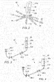
- Fig. 2 is a schematic view of a probe 40 for use in the system 20 of Fig. 1 .
- the medical procedure system 20 is used to determine the position of the probe 40, seen in an inset 25 of Fig. 1 and in more detail in Fig. 2 .
- the probe 40 includes a shaft 22 and a plurality of deflectable arms 54 (only some labeled for the sake of simplicity) for inserting into a body-part of a living subject.
- the deflectable arms 54 have respective proximal ends connected to the distal end of the shaft 22.
- the probe 40 includes a position sensor 53 disposed on the shaft 22 in a predefined spatial relation to the proximal ends of the deflectable arms 54.
- the position sensor 53 may include a magnetic sensor 50 and/or at least one shaft electrode 52.
- the magnetic sensor 50 may include at least one coil, for example, but not limited to, a dual-axis or a triple axis coil arrangement to provide position data for location and orientation including roll.
- the probe 40 includes multiple electrodes 55 (only some are labeled in Fig. 2 for the sake of simplicity) disposed at different, respective locations along each of the deflectable arms 54.
- the probe 40 may be used for mapping electrical activity in a heart of the living subject using the electrodes 55, or for performing any other suitable function in a body-part of a living subject.
- the medical procedure system 20 may determine a position and orientation of the shaft 22 of the probe 40 based on signals provided by the magnetic sensor 50 and/or the shaft electrodes 52 (proximal-electrode 52a and distal-electrode 52b) fitted on the shaft 22, on either side of the magnetic sensor 50.
- the proximal-electrode 52a, the distal-electrode 52b, the magnetic sensor 50 and at least some of the electrodes 55 are connected by wires running through the shaft 22 via a probe connector 35 to various driver circuitries in a console 24.
- at least two of the electrodes 55 of each of the deflectable arms 54, the shaft electrodes 52, and the magnetic sensor 50 are connected to the driver circuitries in the console 24 via the probe connector 35.
- the distal-electrode 52b and/or the proximal electrode 52a may be omitted.
- Fig. 2 The illustration shown in Fig. 2 is chosen purely for the sake of conceptual clarity. Other configurations of shaft electrodes 52 and electrodes 55 are possible. Additional functionalities may be included in the position sensor 53. Elements which are not relevant to the disclosed embodiments of the invention, such as irrigation ports, are omitted for the sake of clarity.
- a physician 30 navigates the probe 40 to a target location in a body part (e.g., a heart 26) of a patient 28 by manipulating the shaft 22 using a manipulator 32 near the proximal end of the probe 40 and/or deflection from a sheath 23.
- the probe 40 is inserted through the sheath 23, with the deflectable arms 54 gathered together, and only after the probe 40 is retracted from the sheath 23, the deflectable arms 54 are able to spread and regain their intended functional shape.
- the sheath 23 also serves to minimize vascular trauma on its way to the target location.
- Console 24 comprises processing circuitry 41, typically a general-purpose computer and a suitable front end and interface circuits 44 for generating signals in, and/or receiving signals from, body surface electrodes 49 which are attached by wires running through a cable 39 to the chest and to the back, or any other suitable skin surface, of the patient 28.
- processing circuitry 41 typically a general-purpose computer and a suitable front end and interface circuits 44 for generating signals in, and/or receiving signals from, body surface electrodes 49 which are attached by wires running through a cable 39 to the chest and to the back, or any other suitable skin surface, of the patient 28.
- Console 24 further comprises a magnetic-sensing sub-system.
- the patient 28 is placed in a magnetic field generated by a pad containing at least one magnetic field radiator 42, which is driven by a unit 43 disposed in the console 24.
- the magnetic field radiator(s) 42 is configured to transmit alternating magnetic fields into a region where the body-part (e.g., the heart 26) is located.
- the magnetic fields generated by the magnetic field radiator(s) 42 generate direction signals in the magnetic sensor 50.
- the magnetic sensor 50 is configured to detect at least part of the transmitted alternating magnetic fields and provide the direction signals as corresponding electrical inputs to the processing circuitry 41.
- the processing circuitry 41 uses the position-signals received from the shaft electrodes 52, the magnetic sensor 50 and the electrodes 55 to estimate a position of the probe 40 inside an organ, such as inside a cardiac chamber. In some embodiments, the processing circuitry 41 correlates the position signals received from the electrodes 52, 55 with previously acquired magnetic location-calibrated position signals, to estimate the position of the probe 40 inside a cardiac chamber. The position coordinates of the shaft electrodes 52 and the electrodes 55 may be determined by the processing circuitry 41 based on, among other inputs, measured impedances, or on proportions of currents distribution, between the electrodes 52, 55 and the body surface electrodes 49.
- the console 24 drives a display 27, which shows the distal end of the probe 40 inside the heart 26.
- the method of position sensing using current distribution measurements and/or external magnetic fields is implemented in various medical applications, for example, in the Carto® system, produced by Biosense Webster Inc. (Irvine, California), and is described in detail in U.S. Patents 5,391,199 , 6,690,963 , 6,484,118 , 6,239,724 , 6,618,612 , 6,332,089 , 7,756,576 , 7,869,865 , and 7,848,787 , in PCT Patent Publication WO 96/05768 , and in U.S. Patent Application Publications 2002/0065455 A1 , 2003/0120150 A1 and 2004/0068178 A1 , whose disclosures are all incorporated herein by reference.
- the Carto®3 system applies an Active Current Location (ACL) impedance-based position-tracking method.
- ACL Active Current Location
- the processing circuitry 41 is configured to create a mapping (e.g., current-position matrix (CPM)) between indications of electrical impedance and positions in a magnetic coordinate frame of the magnetic field radiator(s) 42.
- the processing circuitry 41 estimates the positions of the shaft electrodes 52 and the electrodes 55 by performing a lookup in the CPM.
- a mapping e.g., current-position matrix (CPM)
- Processing circuitry 41 is typically programmed in software to carry out the functions described herein.
- the software may be downloaded to the computer in electronic form, over a network, for example, or it may, alternatively or additionally, be provided and/or stored on non-transitory tangible media, such as magnetic, optical, or electronic memory.
- Fig. 1 shows only elements related to the disclosed techniques, for the sake of simplicity and clarity.
- the system 20 typically comprises additional modules and elements that are not directly related to the disclosed techniques, and thus are intentionally omitted from Fig. 1 and from the corresponding description.
- Fig. 3 is a schematic view of one of the deflectable arms 54 of the probe 40 of Fig. 2.
- Fig. 3 shows the electrodes 55 labeled individually from 55-1 to 55-6.
- the electrode 55-1 is closest to the distal end of the deflectable arm 54, while the electrode 55-6 is closest to the proximal end of the deflectable arm 54.
- the electrode 55-3 is closest to the weakest part of the deflectable arm 54 which in Fig. 3 is indicated by the deflectable arm 54 being the most curved near the electrode 55-3.
- Fig. 4 is a schematic view of the arm 54 of Fig. 3 illustrating computation of position coordinates of a proximal end 57 of the deflectable arm 54 of Fig. 3 .
- the proximal end 57 of the deflectable arm 54 may be computed responsively to: the predefined spatial relation between the position sensor 53 (e.g., the magnetic sensor 50 and/or the shaft electrodes 52) and the proximal ends 57 of the deflectable arms 54; and computed position coordinates of the magnetic sensor 50 and/or computed position coordinates of the shaft electrodes 52.
- the electrodes 55-1 and 55-3 (which comprise a minority of the six electrodes 55 on the deflectable arm 54) have been selected in the example of Fig. 4 to be connected to the console 24 ( Fig. 1 ) via the probe connector 35 ( Fig. 1 ) to provide signals for use in computing the position coordinates of the electrodes 55-1 and 55-3. Therefore, for the eight deflectable arms 54 of the probe 40 there are sixteen connections from the electrodes 55 and two connections from the shaft electrode 52 to the console 24 via the probe connector 35. It should be noted that more other electrodes 55 may be connected to the console 24 or an auxiliary unit for measuring electrical activity of the body-part (e.g., the heart 26).
- the electrode 55-1 is the closest to the distal end of the deflectable arm 54 (and therefore furthest from the shaft 22) while the electrode 55-3 is closest to the weakest part of the deflectable arm 54. Therefore, the electrodes 55-1, 55-3 are suitable candidates for use in fitting a curve to determine the shape of the deflectable arm 54.
- the computed position coordinates of the electrodes 55-1, 55-3 and the proximal end 57 provide data for fitting a curve, described in more detail with reference to Fig. 5 .
- Fig. 5 is a schematic view of the arm 54 of Fig. 3 illustrating fitting a curve 59 based on the computed position coordinates of the proximal end 57 of the deflectable arm 54 and computed position coordinates of two electrodes 55-1, 55-3 of the deflectable arm 54.
- the fitting of the curve 59 may be performed using any suitable curve fitting method, for example, but not limited to, a Bezier curve.
- a Bezier curve is a smooth curve that is typically defined by two end points (e.g., the position coordinates of the electrode 55-1 and the proximal end 57) and at least one midpoint (e.g., the position coordinates of the electrode 55-3).
- the Bezier method defines a curve which goes through the two end-points and is influenced (e.g., pulled) by the mid-point(s).
- the Bezier curve may, or may not, go through the midpoint(s).
- a quadratic Bezier curve may be used to provide curve fitting for three data points.
- a cubic Bezier curve may be used to provide curve fitting for four data points.
- Higher order Bezier curves may be used to provide curve fitting for more than four data points.
- Fig. 6 is a schematic view illustrating computed electrode positions along the fitted curve 59 of Fig. 5 .
- Position coordinates of at least some, and generally all, of the multiple electrodes 55 of each of the deflectable arms 54 are computed responsively to the respective fitted curve 59 and the respective locations of the multiple electrodes 55 (for which the computing is currently being performed) along the respective deflectable arm 54.
- the computation step uses the respective fitted curve 59 and the known locations of the electrodes 55 along the respective deflectable arm 54 as input to compute (estimate) the positions of the electrodes 55 assuming the electrodes 55 are located on the respective fitted curve 59 according to the known locations of the electrodes 55 along the respective arm 54.
- the known locations (spacing) of the electrodes 55 along the arms 54 may be used to compute the position coordinates of the electrodes 55 along the respective curve 59 either starting at the end of the respective curve 59 corresponding with the position of the electrode 55-1 or from the end of the respective curve 59 corresponding with the proximal end 57.
- Fig. 7 is a schematic view of a graphical representation of part of the probe 40 of Fig. 2 on a display screen rendered according to the computed electrode positions of Fig. 6 .
- the graphical representation of each deflectable arm 55 may be based on connecting the computed electrode positions of the respective arm 54, the computed position of the proximal end 57 of the respective arm 54, and the end of the respective arm 54 (computed from the known length of the respective arm 54 from its proximal end 57) with straight lines or curves.
- Representations of the electrodes 55 may be rendered on the deflectable arms 54 according to the computed position coordinates of the electrodes 55 (computed in the step of block 72).
- the shaft 22 may be computed based on the computed positions of the shaft electrode(s) 52 and/or the magnetic sensor 50.
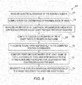
- Fig. 8 is a flowchart 60 including exemplary steps in a method for use in the system 20 of Fig. 1 .
- the processing circuitry 41 is configured to measure (block 62) electrical readings of the position sensor 53.
- the processing circuitry 41 is configured to compute (block 64) position coordinates of the proximal ends 57 of the deflectable arms 54 responsively to the measured electrical readings and the predefined spatial relation between the position sensor 53 and the proximal ends 57 of the deflectable arms 54.
- the position coordinates of the proximal end 57 may be computed based on a computed position of the magnetic sensor 50.
- the processing circuitry 41 is configured to measure an indication of electrical impedances between the body surface electrodes 49 and the shaft electrode(s) 52 and compute the position coordinates of the proximal ends 57 of the deflectable arms 54 responsively to the measured indication of electrical impedances and the predefined spatial relation between the position sensor 53 (e.g., the shaft electrode(s) 52) and the proximal ends 57 of the deflectable arms 54.
- the processing circuitry 41 is configured to measure (block 66) an indication of electrical impedances between the body surface electrodes 49 and at least two of the multiple electrodes 55 (e.g., the electrode 55-1, and the electrode 55-3) of each of the deflectable arms 54.
- the processing circuitry 41 is configured to compute (block 68) position coordinates of each of the at least two electrodes 55 on each of the deflectable arms 54 responsively to the indication of the electrical impedances measured in the step of block 66.
- the processing circuitry 41 is configured to fit (block 70) a respective curve 59 corresponding to each deflectable arm 54 responsively to the respective position coordinates of the position sensor 53 and the position coordinates of each of the respective at least two electrodes 55.
- the processing circuitry 41 is configured to fit the curve 59 for each of the deflectable arms 54 based on a Bezier curve.
- the fitting of the curve 59 may be performed according to any suitable curve fitting method.
- the processing circuitry 41 is configured to compute (block 72) position coordinates of at least some, and generally all, of the multiple electrodes 55 of each of the deflectable arms 54 responsively to the respective fitted curve 59 and the respective locations of the multiple electrodes 55 (for which the computing is currently being performed) along the respective deflectable arm 54.
- the computation step of block 72 estimates where the electrodes 55 would be positioned assuming that the electrodes 55 are positioned along the respective fitted curve 59.
- the computation step of block 72 uses the respective fitted curve 59 and the known locations of the electrodes 55 along the respective deflectable arm 54 as input to compute (estimate) the positions of the electrodes 55 assuming the electrodes 55 are located on the respective fitted curve 59 according to the known locations of the electrodes 55 along each of the arms 54.
- the known locations (spacing) of the electrodes 55 along the arms 54 may be used to compute the position coordinates of the electrodes 55 along the respective curve 59 either starting at the end of the respective curve 59 corresponding with the position of the electrode 55-1 or from the end of the respective curve 59 corresponding with the proximal end 57.
- the processing circuitry 41 is configured to render (block 74) to the display 27 a graphical representation of the probe 40 including a graphical representation of the shaft 22, and a graphical representation of the deflectable arms 54 including the electrode 55 responsively to the computed position coordinates of the electrodes 55 (which were computed responsively to the respective fitted curve 57.
- the graphical representation of each deflectable arm 54 may be based on connecting the computed position coordinates of the electrodes 55 (computed in the step of block 72) of the respective arm 54, the computed position of the proximal end 57 of the respective arm 54, and the end of the respective arm 54 (from the known length of the respective arm 54 from the proximal end 57) with straight lines or curves.
- Representations of the electrodes 55 may be rendered on the deflectable arms 54 according to the computed position coordinates of the electrodes 55 (computed in the step of block 72).
- the shaft 22 may be computed based on the computed positions of the shaft electrode(s) 52 and/or the magnetic sensor 50.
- FIG. 2 An example of a graphical representation of the probe 40 is shown in Fig. 2 and a portion of the probe 40 is shown in Fig. 7 .
- the representation of the probe 40 and the relevant spine 54 with electrodes 55-1; 55-2; 55-3; 55-4; 55-5; and 55-6 of probe 40 may be displayed on display screen 27 ( Fig. 1 ) over a previously acquired body-part scan such as a CT scan or MRI scan of the heart (or any other organ), which is registered and merged with a position tracking system (e.g., Carto 3 system by Biosense Ltd., Irvine, CA) tracking the probe 40, thereby allowing the physician 30 to successfully navigate the probe 40 in the body-part in real-time by observing the display screen 27.
- a position tracking system e.g., Carto 3 system by Biosense Ltd., Irvine, CA
- all of the spines 54 and their respective electrodes for probe 40 can also be determined and rendered visually with all spines and electrodes (e.g., Fig. 2 ) on a display screen overlaying anatomical images previously acquired or generated by the Carto3 system.
Landscapes
- Health & Medical Sciences (AREA)
- Life Sciences & Earth Sciences (AREA)
- Engineering & Computer Science (AREA)
- Surgery (AREA)
- Public Health (AREA)
- Veterinary Medicine (AREA)
- Biomedical Technology (AREA)
- Heart & Thoracic Surgery (AREA)
- Medical Informatics (AREA)
- Molecular Biology (AREA)
- Animal Behavior & Ethology (AREA)
- General Health & Medical Sciences (AREA)
- Pathology (AREA)
- Physics & Mathematics (AREA)
- Biophysics (AREA)
- Nuclear Medicine, Radiotherapy & Molecular Imaging (AREA)
- Radiology & Medical Imaging (AREA)
- Human Computer Interaction (AREA)
- Robotics (AREA)
- Physiology (AREA)
- Cardiology (AREA)
- Oral & Maxillofacial Surgery (AREA)
- Gynecology & Obstetrics (AREA)
- Measurement And Recording Of Electrical Phenomena And Electrical Characteristics Of The Living Body (AREA)
Abstract
Description
- The present invention relates to medical devices, and in particular, but not exclusively, to multi-arm probes.
- Tracking the position of intrabody probes, such as insertion tubes, catheters and implants, is required for many medical procedures. A representation of the tracked probe may be displayed over a previously acquired body-part scan such as a CT, which is registered with a position tracking system tracking the probe, thereby allowing a physician to successfully navigate the probe in the body-part. For example,
US Patent Publication 2017/0332971 of Macneil, et al. , describes a system to generate a representation of a rhythm disorder that includes identifying remote or polar sources associated with a cardiac rhythm disorder. The system includes generating a representation based on cardiac information signals received from sensors by transformation of spline-sensor locations of a catheter to x-y coordinate pairs of locations. A first offset is determined resulting from a perturbation to corresponding x-y coordinate pairs of locations associated with the representation, the first offset displacing coordinate pairs of sensor locations of the representation by at least one unit of displacement in a first direction. A remote source associated with a cardiac rhythm disorder is identified when activations associated with the cardiac information signals rotate in sequence at least once, or emanate centrifugally for at least a first time period, the source being identified based on the representation as displaced. -
US Patent Publication 2018/0303361 of Wu, et al. , describes a catheter adapted for high density mapping and/or ablation of a tissue surface and has a distal electrode array with offset spine loops, each spine loop having at least a pair of linear portions and a distal portion connecting the pair of linear portions, and one or more electrodes on each linear portion. The linear portions of the plurality of offset spine loops are arranged in-plane of a single common plane, and the distal portions of the plurality of offset spine loops are arranged off-plane from the single common plane. -
US Patent 6,574,492 to Ben-Haim, et al. , describes a catheter for measuring physiological signals in a heart and comprises a structure at a distal end of the catheter wherein the structure has a plurality of arms, an electrode fixed to each arm and a device for generating position information located on each arm. The arms are located near the long axis of the catheter during insertion of the catheter within a heart and the arms are spreadable apart and away from the long axis of the catheter when the structure is within the heart. -
US Patent Publication 2015/0351652 of Marecki, et al. , describes an expandable electrode assembly for use in a cardiac mapping procedure and includes multiple bipolar electrode pairs including a first electrode located on an outer surface and a second electrode located on an inner surface of the individual splines forming the expandable electrode assembly. Such an electrode arrangement may produce improved electrical activation signals which may be used to produce a more accurate map of the electrical activity of a patient's heart. - There is provided in accordance with an embodiment of the present disclosure, a medical procedure system, including a plurality of body surface electrodes configured to be applied to a skin surface of a living subject, a probe configured for inserting into a body-part of the living subject and including a shaft, a plurality of deflectable arms having respective proximal ends connected to a distal end of the shaft, a position sensor disposed on the shaft in a predefined spatial relation to the proximal ends of the deflectable arms, and multiple electrodes disposed at different, respective locations along each of the deflectable arms, and processing circuitry configured to measure electrical readings of the position sensor, compute first position coordinates of the proximal ends of the deflectable arms responsively to the measured electrical readings and the predefined spatial relation between the position sensor and the proximal ends of the deflectable arms, measure an indication of electrical impedances between the body surface electrodes and at least two of the multiple electrodes of each of the deflectable arms, compute second position coordinates of each of the at least two electrodes on each of the deflectable arms responsively to the indication of the electrical impedances, fit a respective curve corresponding to each of the deflectable arms responsively to the respective first position coordinates of the proximal end of the respective deflectable arm and the second position coordinates of each of the respective at least two electrodes, and render to the display a graphical representation of the probe including a graphical representation of the shaft, and a graphical representation of the deflectable arms responsively to the respective fitted curve.
- Further in accordance with an embodiment of the present disclosure the processing circuitry is configured to compute third position coordinates of at least some of the multiple electrodes of each of the deflectable arms responsively to the respective fitted curve and the respective locations of the at least some multiple electrodes along the respective deflectable arm, and render to the display a graphical representation of the probe including a graphical representation of the shaft, and a graphical representation of the deflectable arms and the multiple electrodes responsively to the computed third position coordinates.
- Still further in accordance with an embodiment of the present disclosure, the system includes a probe connector configured to couple the position sensor, and the at least two electrodes of each of the deflectable arms to the processing circuitry.
- Additionally in accordance with an embodiment of the present disclosure the position sensor includes at least one shaft electrode, the processing circuitry being configured to measure another indication of electrical impedances between the body surface electrodes and the at least one shaft electrode, and compute the first position coordinates of the proximal ends of the deflectable arms responsively to the other indication of electrical impedances and the predefined spatial relation between the position sensor and the proximal ends of the deflectable arms.
- Moreover, in accordance with an embodiment of the present disclosure at least two electrodes of each of the deflectable arms include only some of the multiple electrodes of each of the deflectable arms.
- Further in accordance with an embodiment of the present disclosure the at least two electrodes of respective ones of the deflectable arms include a respective one of the multiple electrodes disposed furthest from the shaft.
- Still further in accordance with an embodiment of the present disclosure the at least two electrodes include one of the multiple electrodes closest to a weakest part of the respective one of the deflectable arms, and the at least two electrodes of each of the deflectable arms include only some of the multiple electrodes of each of the deflectable arms
- Additionally in accordance with an embodiment of the present disclosure the position sensor includes a magnetic sensor and at least one shaft electrode, the system further including a least one magnetic field radiator configured to transmit alternating magnetic fields into a region where the body-part is located, the magnetic sensor being configured to detect at least part of the transmitted alternating magnetic fields, the processing circuitry being configured to create a mapping between indications of electrical impedance and positions in a magnetic coordinate frame of the at least one magnetic field radiator.
- Moreover, in accordance with an embodiment of the present disclosure the processing circuitry is configured to fit the curve for each of the deflectable arms based on a Bezier curve.
- Further in accordance with an embodiment of the present disclosure the at least two electrodes of respective ones of the deflectable arms include a respective one of the multiple electrodes disposed furthest from the shaft, and the at least two electrodes include one of the multiple electrodes closest to a weakest part of the respective one of the deflectable arms.
- There is also provided in accordance with another embodiment of the present disclosure, a medical procedure method, including applying a plurality of body surface electrodes to a skin surface of a living subject, inserting a probe into a body-part of the living subject, the probe including a shaft, a plurality of deflectable arms having respective proximal ends connected to a distal end of the shaft, a position sensor disposed on the shaft in a predefined spatial relation to the proximal ends of the deflectable arms, and multiple electrodes disposed at different, respective locations along each of the deflectable arms, measuring electrical readings of the position sensor, computing first position coordinates of the proximal ends of the deflectable arms responsively to the measured electrical readings and the predefined spatial relation between the position sensor and the proximal ends of the deflectable arms, measuring an indication of electrical impedances between the body surface electrodes and at least two of the multiple electrodes of each of the deflectable arms, computing second position coordinates of each of the at least two electrodes on each of the deflectable arms responsively to the indication of the electrical impedances, fitting a respective curve corresponding to each of the deflectable arms responsively to the respective first position coordinates of the proximal end of the respective deflectable arm and the second position coordinates of each of the respective at least two electrodes, and rendering to a display a graphical representation of the probe including a graphical representation of the shaft, and a graphical representation of the deflectable arms responsively to the respective fitted curve.
- Still further in accordance with an embodiment of the present disclosure, the method includes computing third position coordinates of at least some of the multiple electrodes of each of the deflectable arms responsively to the respective fitted curve and the respective locations of the at least some multiple electrodes along the respective deflectable arm, and wherein the rendering including rendering to the display a graphical representation of the probe including a graphical representation of the shaft, and a graphical representation of the deflectable arms and the multiple electrodes responsively to the computed third position coordinates.
- Additionally in accordance with an embodiment of the present disclosure the position sensor includes at least one shaft electrode, the method further including measuring another indication of electrical impedances between the body surface electrodes and the at least one shaft electrode, and computing the first position coordinates of the proximal ends of the deflectable arms responsively to the other indication of electrical impedances and the predefined spatial relation between the position sensor and the proximal ends of the deflectable arms.
- Moreover, in accordance with an embodiment of the present disclosure at least two electrodes of each of the deflectable arms include only some of the multiple electrodes of each of the deflectable arms.
- Further in accordance with an embodiment of the present disclosure the at least two electrodes of respective ones of the deflectable arms include a respective one of the multiple electrodes disposed furthest from the shaft.
- Still further in accordance with an embodiment of the present disclosure the at least two electrodes include one of the multiple electrodes closest to a weakest part of the respective one of the deflectable arms, and the at least two electrodes of each of the deflectable arms include only some of the multiple electrodes of each of the deflectable arms
- Additionally in accordance with an embodiment of the present disclosure the position sensor includes a magnetic sensor and at least one shaft electrode, the method further including transmitting alternating magnetic fields into a region where the body-part is located, detecting at least part of the transmitted alternating magnetic fields by the magnetic sensor, and creating a mapping between indications of electrical impedance and positions in a magnetic coordinate frame.
- Moreover, in accordance with an embodiment of the present disclosure the fitting includes fitting the curve for each of the deflectable arms based on a Bezier curve.
- Further in accordance with an embodiment of the present disclosure the at least two electrodes of respective ones of the deflectable arms include a respective one of the multiple electrodes disposed furthest from the shaft, and the at least two electrodes include one of the multiple electrodes closest to a weakest part of the respective one of the deflectable arms.
- The present invention will be understood from the following detailed description, taken in conjunction with the drawings in which:
-
Fig. 1 is a schematic view of a medical procedure system constructed and operative in accordance with an embodiment of the present invention; -
Fig. 2 is a schematic view of a probe for use in the system ofFig. 1 ; -
Fig. 3 is a schematic view of one of the deflectable arms of the probe ofFig. 2 ; -
Fig. 4 is a schematic view of the arm ofFig. 3 illustrating computation of position coordinates of a proximal end of the deflectable arm ofFig. 3 ; -
Fig. 5 is a schematic view of the arm ofFig. 3 illustrating fitting a curve based on the computed position coordinates of the proximal end of the deflectable arm and computed position coordinates of two electrodes of the deflectable arm; -
Fig. 6 is a schematic view illustrating computed electrode positions along the fitted curve ofFig. 5 ; -
Fig. 7 is a schematic view of a graphical representation of part of the probe ofFig. 2 rendered as a graphical overlay into an image of the heart according to the computed electrode positions ofFig. 6 ; and -
Fig. 8 is a flowchart including exemplary steps in a method for use in the system ofFig. 1 . - As mentioned above, tracking the position of intrabody probes, such as insertion tubes, catheters and implants, is required for many medical procedures. A representation of a tracked probe may be displayed over a previously acquired body-part scan such as a CT image, which is registered with a position tracking system tracking the probe, thereby allowing a physician to successfully navigate the probe in the body-part.
- Accurately rendering the tracked probe to a display may be difficult due to various reasons. For example, if the probe is flexible or deflectable, computing the location of the various parts of the probe may be limited by the number and location of position sensors on the probe.
- In some systems, the number of position sensors which may be connected to a position tracking system may be limited by the capabilities of the position tracking system. For example, if the probe includes fifty electrodes for position tracking, but the position tracking system has a smaller number of input terminals, such as twenty terminals, for connection to the electrodes, computing the locations of only twenty of the electrodes may not provide an accurate enough picture of the various parts of the probe. An example of a fifty-electrode probe is the Octaray® catheter produced by Biosense Webster Inc., of Irvine, CA, USA. The Octaray includes eight deflectable arms disposed at the distal end of a shaft, with each of the deflectable arms including six electrodes and another two electrodes disposed on the shaft on either side of a magnetic sensor. An example of a five-arm probe is the Pentaray® catheter of Biosense Webster Inc.
- Embodiments of the invention provide a system and method that address these problems, in order to accurately estimate the disposition of a probe having multiple deflectable arms within the body of a living subject. These embodiments take advantage of prior knowledge of the geometrical and mechanical properties of the probe, and particularly of its arms, in order to produce an accurate graphical representation of the probe while using only a small number of position sensors along each of the arms. Thus, the present embodiments improve the reliability of image display while reducing the data input requirements of the system.
- In the disclosed embodiments, each of the arms has a proximal end connected to a shaft of the probe and a distal end furthest from the shaft. The distal end has free movement subject to the flexibility of the arm and the various obstacles encountered in the body of the living subject. The arms include electrodes disposed at different, respective locations along each deflectable arm. The probe may include any suitable number of deflectable arms, for example, but not limited to, five or eight. Each of the arms may include any suitable number of electrodes, for example, but not limited to, two or more electrodes.
- The disposition of each arm is estimated based on fitting a curve to computed position coordinates of at least three points along the respective arm. As will be explained in more detail below, the disposition of each of the arms may be estimated based on position data provided by a minimal number of arm electrodes, which is particularly advantageous when the position tracking system has a smaller number of input terminals for connection to the electrodes.
- The position coordinates of one of the points (first point) used in the curve fitting may be based on computed position coordinates of an electrode disposed close to the distal tip of the respective arm.
- The position coordinates of another one of the points (second point) used in the curve fitting may be based on computed position coordinates of the proximal end of the respective arm. In some embodiments, the position coordinates of the proximal end of the respective arm may be computed based on position sensing of a position sensor disposed on the shaft and a predefined spatial relation between the shaft position sensor and the proximal end of the respective arm.
- The position coordinates of yet another point (third point) used in the curve fitting may be based on the computed position coordinates of an electrode disposed on the respective arm between the electrode close to the distal tip and the proximal end of the respective arm. In some embodiments, the computed position coordinates of the third point are used in the curve fitting may be selected based on the electrode closest to the weakest part of each arm. The weakest part of the arm is typically the part of the arm that bends through the largest angle and/or with the smallest bend radius, and therefore provides particularly relevant data for use in fitting the curves to estimate the dispositions of the deflectable arms.
- Processing circuitry measures electrical readings of the position sensor disposed on the shaft and computes first position coordinates of the proximal ends of the deflectable arms responsively to the measured electrical readings and the predefined spatial relation between the position sensor and the proximal ends of the deflectable arms.
- For the purposes of tracking the electrode locations on the probe, body surface electrodes are applied to the skin surface of the living subject. The processing circuitry measures an indication of electrical impedances between the body surface electrodes and the arm electrodes used to provide position coordinates used in the curve fitting. In some embodiments, the arm electrodes used in the curve fitting may comprise only some of the multiple electrodes of each of the deflectable arms. In other embodiment, the arm electrodes used in the curve fitting may comprise all of the electrodes of each of the deflectable arms.
- The processing circuitry computes second position coordinates of each of the electrodes used in the curve fitting responsively to the indication of the electrical impedances.
- The processing circuitry fits a respective curve corresponding to each of the deflectable arms responsively to the respective first position coordinates of the proximal end of the respective arm and the second position coordinates of each of the respective electrodes. Fitting the curves may be based on a Bezier curve or any other suitable curve fitting method.
- The processing circuitry computes position coordinates of at least some, and generally all, of the electrodes of each of the deflectable arms responsively to the respective fitted curve and the respective locations of the electrodes (for which the computing is currently being performed) along the respective deflectable arm. The computation estimates where the electrodes would be positioned assuming that the electrodes are positioned along the respective fitted curve and the electrodes are located on the respective fitted curve according to the known locations of the electrodes along each of the arms.
- The processing circuitry renders to a display a graphical representation of the probe including a graphical representation of the shaft, and a graphical representation of the deflectable arms with the electrodes responsively to the computed positions of the electrodes. The graphical representation of each deflectable arm may be based on connecting the computed position coordinates of the electrodes of the respective deflectable arm, the computed position of the proximal end of the respective deflectable arm, and the end of the respective deflectable arm (computed from a known length of the arm from the proximal end) with straight lines or curves. Representations of the electrodes may be rendered on the deflectable arms according to the computed position coordinates of the electrodes.
- Documents incorporated by reference herein are to be considered an integral part of the application except that, to the extent that any terms are defined in these incorporated documents in a manner that conflicts with definitions made explicitly or implicitly in the present specification, only the definitions in the present specification should be considered.
- Reference is now made to
Fig. 1 , which is a schematic view of amedical procedure system 20 constructed and operative in accordance with an embodiment of the present invention. Reference is also made toFig. 2 , which is a schematic view of aprobe 40 for use in thesystem 20 ofFig. 1 . - The
medical procedure system 20 is used to determine the position of theprobe 40, seen in aninset 25 ofFig. 1 and in more detail inFig. 2 . Theprobe 40 includes ashaft 22 and a plurality of deflectable arms 54 (only some labeled for the sake of simplicity) for inserting into a body-part of a living subject. Thedeflectable arms 54 have respective proximal ends connected to the distal end of theshaft 22. - The
probe 40 includes aposition sensor 53 disposed on theshaft 22 in a predefined spatial relation to the proximal ends of thedeflectable arms 54. Theposition sensor 53 may include amagnetic sensor 50 and/or at least one shaft electrode 52. Themagnetic sensor 50 may include at least one coil, for example, but not limited to, a dual-axis or a triple axis coil arrangement to provide position data for location and orientation including roll. Theprobe 40 includes multiple electrodes 55 (only some are labeled inFig. 2 for the sake of simplicity) disposed at different, respective locations along each of thedeflectable arms 54. Typically, theprobe 40 may be used for mapping electrical activity in a heart of the living subject using theelectrodes 55, or for performing any other suitable function in a body-part of a living subject. - The
medical procedure system 20 may determine a position and orientation of theshaft 22 of theprobe 40 based on signals provided by themagnetic sensor 50 and/or the shaft electrodes 52 (proximal-electrode 52a and distal-electrode 52b) fitted on theshaft 22, on either side of themagnetic sensor 50. The proximal-electrode 52a, the distal-electrode 52b, themagnetic sensor 50 and at least some of theelectrodes 55 are connected by wires running through theshaft 22 via aprobe connector 35 to various driver circuitries in aconsole 24. In some embodiments, at least two of theelectrodes 55 of each of thedeflectable arms 54, the shaft electrodes 52, and themagnetic sensor 50 are connected to the driver circuitries in theconsole 24 via theprobe connector 35. In some embodiments, the distal-electrode 52b and/or theproximal electrode 52a may be omitted. - The illustration shown in
Fig. 2 is chosen purely for the sake of conceptual clarity. Other configurations of shaft electrodes 52 andelectrodes 55 are possible. Additional functionalities may be included in theposition sensor 53. Elements which are not relevant to the disclosed embodiments of the invention, such as irrigation ports, are omitted for the sake of clarity. - A
physician 30 navigates theprobe 40 to a target location in a body part (e.g., a heart 26) of a patient 28 by manipulating theshaft 22 using amanipulator 32 near the proximal end of theprobe 40 and/or deflection from asheath 23. Theprobe 40 is inserted through thesheath 23, with thedeflectable arms 54 gathered together, and only after theprobe 40 is retracted from thesheath 23, thedeflectable arms 54 are able to spread and regain their intended functional shape. By containingdeflectable arms 54 together, thesheath 23 also serves to minimize vascular trauma on its way to the target location. -
Console 24 comprises processingcircuitry 41, typically a general-purpose computer and a suitable front end andinterface circuits 44 for generating signals in, and/or receiving signals from,body surface electrodes 49 which are attached by wires running through acable 39 to the chest and to the back, or any other suitable skin surface, of thepatient 28. -
Console 24 further comprises a magnetic-sensing sub-system. Thepatient 28 is placed in a magnetic field generated by a pad containing at least onemagnetic field radiator 42, which is driven by aunit 43 disposed in theconsole 24. The magnetic field radiator(s) 42 is configured to transmit alternating magnetic fields into a region where the body-part (e.g., the heart 26) is located. The magnetic fields generated by the magnetic field radiator(s) 42 generate direction signals in themagnetic sensor 50. Themagnetic sensor 50 is configured to detect at least part of the transmitted alternating magnetic fields and provide the direction signals as corresponding electrical inputs to theprocessing circuitry 41. - In some embodiments, the
processing circuitry 41 uses the position-signals received from the shaft electrodes 52, themagnetic sensor 50 and theelectrodes 55 to estimate a position of theprobe 40 inside an organ, such as inside a cardiac chamber. In some embodiments, theprocessing circuitry 41 correlates the position signals received from theelectrodes 52, 55 with previously acquired magnetic location-calibrated position signals, to estimate the position of theprobe 40 inside a cardiac chamber. The position coordinates of the shaft electrodes 52 and theelectrodes 55 may be determined by theprocessing circuitry 41 based on, among other inputs, measured impedances, or on proportions of currents distribution, between theelectrodes 52, 55 and thebody surface electrodes 49. Theconsole 24 drives adisplay 27, which shows the distal end of theprobe 40 inside theheart 26. - The method of position sensing using current distribution measurements and/or external magnetic fields is implemented in various medical applications, for example, in the Carto® system, produced by Biosense Webster Inc. (Irvine, California), and is described in detail in
U.S. Patents 5,391,199 ,6,690,963 ,6,484,118 ,6,239,724 ,6,618,612 ,6,332,089 ,7,756,576 ,7,869,865 , and7,848,787 , inPCT Patent Publication WO 96/05768 U.S. Patent Application Publications 2002/0065455 A1 ,2003/0120150 A1 and2004/0068178 A1 , whose disclosures are all incorporated herein by reference. - The Carto®3 system applies an Active Current Location (ACL) impedance-based position-tracking method. In some embodiments, using the ACL method, the
processing circuitry 41 is configured to create a mapping (e.g., current-position matrix (CPM)) between indications of electrical impedance and positions in a magnetic coordinate frame of the magnetic field radiator(s) 42. Theprocessing circuitry 41 estimates the positions of the shaft electrodes 52 and theelectrodes 55 by performing a lookup in the CPM. -
Processing circuitry 41 is typically programmed in software to carry out the functions described herein. The software may be downloaded to the computer in electronic form, over a network, for example, or it may, alternatively or additionally, be provided and/or stored on non-transitory tangible media, such as magnetic, optical, or electronic memory. -
Fig. 1 shows only elements related to the disclosed techniques, for the sake of simplicity and clarity. Thesystem 20 typically comprises additional modules and elements that are not directly related to the disclosed techniques, and thus are intentionally omitted fromFig. 1 and from the corresponding description. - Reference is now made to
Fig. 3 , which is a schematic view of one of thedeflectable arms 54 of theprobe 40 ofFig. 2. Fig. 3 shows theelectrodes 55 labeled individually from 55-1 to 55-6. The electrode 55-1 is closest to the distal end of thedeflectable arm 54, while the electrode 55-6 is closest to the proximal end of thedeflectable arm 54. The electrode 55-3 is closest to the weakest part of thedeflectable arm 54 which inFig. 3 is indicated by thedeflectable arm 54 being the most curved near the electrode 55-3. - Reference is now made to
Fig. 4 , which is a schematic view of thearm 54 ofFig. 3 illustrating computation of position coordinates of aproximal end 57 of thedeflectable arm 54 ofFig. 3 . Theproximal end 57 of thedeflectable arm 54 may be computed responsively to: the predefined spatial relation between the position sensor 53 (e.g., themagnetic sensor 50 and/or the shaft electrodes 52) and the proximal ends 57 of thedeflectable arms 54; and computed position coordinates of themagnetic sensor 50 and/or computed position coordinates of the shaft electrodes 52. - The electrodes 55-1 and 55-3 (which comprise a minority of the six
electrodes 55 on the deflectable arm 54) have been selected in the example ofFig. 4 to be connected to the console 24 (Fig. 1 ) via the probe connector 35 (Fig. 1 ) to provide signals for use in computing the position coordinates of the electrodes 55-1 and 55-3. Therefore, for the eightdeflectable arms 54 of theprobe 40 there are sixteen connections from theelectrodes 55 and two connections from the shaft electrode 52 to theconsole 24 via theprobe connector 35. It should be noted that moreother electrodes 55 may be connected to theconsole 24 or an auxiliary unit for measuring electrical activity of the body-part (e.g., the heart 26). - As mentioned above with reference to
Fig. 3 , the electrode 55-1 is the closest to the distal end of the deflectable arm 54 (and therefore furthest from the shaft 22) while the electrode 55-3 is closest to the weakest part of thedeflectable arm 54. Therefore, the electrodes 55-1, 55-3 are suitable candidates for use in fitting a curve to determine the shape of thedeflectable arm 54. - The computed position coordinates of the electrodes 55-1, 55-3 and the
proximal end 57 provide data for fitting a curve, described in more detail with reference toFig. 5 . - Reference is now made to
Fig. 5 , which is a schematic view of thearm 54 ofFig. 3 illustrating fitting acurve 59 based on the computed position coordinates of theproximal end 57 of thedeflectable arm 54 and computed position coordinates of two electrodes 55-1, 55-3 of thedeflectable arm 54. - The fitting of the
curve 59 may be performed using any suitable curve fitting method, for example, but not limited to, a Bezier curve. A Bezier curve is a smooth curve that is typically defined by two end points (e.g., the position coordinates of the electrode 55-1 and the proximal end 57) and at least one midpoint (e.g., the position coordinates of the electrode 55-3). The Bezier method defines a curve which goes through the two end-points and is influenced (e.g., pulled) by the mid-point(s). The Bezier curve may, or may not, go through the midpoint(s). - A quadratic Bezier curve may be used to provide curve fitting for three data points. A quadratic Bezier curve is the path traced by the function B(t) given points P0, P1 and P2, where

- A cubic Bezier curve may be used to provide curve fitting for four data points. A cubic Bezier curve is the path traced by the function B(t) given points P0, P1, P2, and P3 where

- Higher order Bezier curves may be used to provide curve fitting for more than four data points.
- Reference is now made to
Fig. 6 , which is a schematic view illustrating computed electrode positions along the fittedcurve 59 ofFig. 5 . - Position coordinates of at least some, and generally all, of the
multiple electrodes 55 of each of thedeflectable arms 54 are computed responsively to the respective fittedcurve 59 and the respective locations of the multiple electrodes 55 (for which the computing is currently being performed) along the respectivedeflectable arm 54. The computation estimates where theelectrodes 55 would be positioned assuming that theelectrodes 55 are positioned along the respective fittedcurve 59. The computation step uses the respective fittedcurve 59 and the known locations of theelectrodes 55 along the respectivedeflectable arm 54 as input to compute (estimate) the positions of theelectrodes 55 assuming theelectrodes 55 are located on the respective fittedcurve 59 according to the known locations of theelectrodes 55 along therespective arm 54. For example, the known locations (spacing) of theelectrodes 55 along thearms 54 may be used to compute the position coordinates of theelectrodes 55 along therespective curve 59 either starting at the end of therespective curve 59 corresponding with the position of the electrode 55-1 or from the end of therespective curve 59 corresponding with theproximal end 57. - Reference is now made to
Fig. 7 , which is a schematic view of a graphical representation of part of theprobe 40 ofFig. 2 on a display screen rendered according to the computed electrode positions ofFig. 6 . The graphical representation of eachdeflectable arm 55 may be based on connecting the computed electrode positions of therespective arm 54, the computed position of theproximal end 57 of therespective arm 54, and the end of the respective arm 54 (computed from the known length of therespective arm 54 from its proximal end 57) with straight lines or curves. Representations of theelectrodes 55 may be rendered on thedeflectable arms 54 according to the computed position coordinates of the electrodes 55 (computed in the step of block 72). Theshaft 22 may be computed based on the computed positions of the shaft electrode(s) 52 and/or themagnetic sensor 50. Reference is now made toFig. 8 , which is aflowchart 60 including exemplary steps in a method for use in thesystem 20 ofFig. 1 . Reference is also made toFigs. 1 and5 . - The
processing circuitry 41 is configured to measure (block 62) electrical readings of theposition sensor 53. Theprocessing circuitry 41 is configured to compute (block 64) position coordinates of the proximal ends 57 of thedeflectable arms 54 responsively to the measured electrical readings and the predefined spatial relation between theposition sensor 53 and the proximal ends 57 of thedeflectable arms 54. - In some embodiments, the position coordinates of the
proximal end 57 may be computed based on a computed position of themagnetic sensor 50. - In some embodiments, the
processing circuitry 41 is configured to measure an indication of electrical impedances between thebody surface electrodes 49 and the shaft electrode(s) 52 and compute the position coordinates of the proximal ends 57 of thedeflectable arms 54 responsively to the measured indication of electrical impedances and the predefined spatial relation between the position sensor 53 (e.g., the shaft electrode(s) 52) and the proximal ends 57 of thedeflectable arms 54. - The
processing circuitry 41 is configured to measure (block 66) an indication of electrical impedances between thebody surface electrodes 49 and at least two of the multiple electrodes 55 (e.g., the electrode 55-1, and the electrode 55-3) of each of thedeflectable arms 54. Theprocessing circuitry 41 is configured to compute (block 68) position coordinates of each of the at least twoelectrodes 55 on each of thedeflectable arms 54 responsively to the indication of the electrical impedances measured in the step ofblock 66. - The
processing circuitry 41 is configured to fit (block 70) arespective curve 59 corresponding to eachdeflectable arm 54 responsively to the respective position coordinates of theposition sensor 53 and the position coordinates of each of the respective at least twoelectrodes 55. In some embodiments, theprocessing circuitry 41 is configured to fit thecurve 59 for each of thedeflectable arms 54 based on a Bezier curve. In other embodiments, the fitting of thecurve 59 may be performed according to any suitable curve fitting method. - The
processing circuitry 41 is configured to compute (block 72) position coordinates of at least some, and generally all, of themultiple electrodes 55 of each of thedeflectable arms 54 responsively to the respective fittedcurve 59 and the respective locations of the multiple electrodes 55 (for which the computing is currently being performed) along the respectivedeflectable arm 54. The computation step ofblock 72 estimates where theelectrodes 55 would be positioned assuming that theelectrodes 55 are positioned along the respective fittedcurve 59. The computation step ofblock 72 uses the respective fittedcurve 59 and the known locations of theelectrodes 55 along the respectivedeflectable arm 54 as input to compute (estimate) the positions of theelectrodes 55 assuming theelectrodes 55 are located on the respective fittedcurve 59 according to the known locations of theelectrodes 55 along each of thearms 54. For example, the known locations (spacing) of theelectrodes 55 along thearms 54 may be used to compute the position coordinates of theelectrodes 55 along therespective curve 59 either starting at the end of therespective curve 59 corresponding with the position of the electrode 55-1 or from the end of therespective curve 59 corresponding with theproximal end 57. - The
processing circuitry 41 is configured to render (block 74) to the display 27 a graphical representation of theprobe 40 including a graphical representation of theshaft 22, and a graphical representation of thedeflectable arms 54 including theelectrode 55 responsively to the computed position coordinates of the electrodes 55 (which were computed responsively to the respective fittedcurve 57. The graphical representation of eachdeflectable arm 54 may be based on connecting the computed position coordinates of the electrodes 55 (computed in the step of block 72) of therespective arm 54, the computed position of theproximal end 57 of therespective arm 54, and the end of the respective arm 54 (from the known length of therespective arm 54 from the proximal end 57) with straight lines or curves. Representations of theelectrodes 55 may be rendered on thedeflectable arms 54 according to the computed position coordinates of the electrodes 55 (computed in the step of block 72). Theshaft 22 may be computed based on the computed positions of the shaft electrode(s) 52 and/or themagnetic sensor 50. - An example of a graphical representation of the
probe 40 is shown inFig. 2 and a portion of theprobe 40 is shown inFig. 7 . The representation of theprobe 40 and therelevant spine 54 with electrodes 55-1; 55-2; 55-3; 55-4; 55-5; and 55-6 ofprobe 40 may be displayed on display screen 27 (Fig. 1 ) over a previously acquired body-part scan such as a CT scan or MRI scan of the heart (or any other organ), which is registered and merged with a position tracking system (e.g., Carto 3 system by Biosense Ltd., Irvine, CA) tracking theprobe 40, thereby allowing thephysician 30 to successfully navigate theprobe 40 in the body-part in real-time by observing thedisplay screen 27. By extension of the technique described and illustrated here, all of thespines 54 and their respective electrodes forprobe 40 can also be determined and rendered visually with all spines and electrodes (e.g.,Fig. 2 ) on a display screen overlaying anatomical images previously acquired or generated by the Carto3 system. - Various features of the invention which are, for clarity, described in the contexts of separate embodiments may also be provided in combination in a single embodiment. Conversely, various features of the invention which are, for brevity, described in the context of a single embodiment may also be provided separately or in any suitable sub-combination.
- The embodiments described above are cited by way of example, and the present invention is not limited by what has been particularly shown and described hereinabove. Rather the scope of the invention includes both combinations and subcombinations of the various features described hereinabove, as well as variations and modifications thereof which would occur to persons skilled in the art upon reading the foregoing description and which are not disclosed in the prior art.
-
- 1. A medical procedure method, comprising:
- applying a plurality of body surface electrodes to a skin surface of a living subject;
- inserting a probe into a body-part of the living subject, the probe comprising: a shaft; a plurality of deflectable arms having respective proximal ends connected to a distal end of the shaft; a position sensor disposed on the shaft in a predefined spatial relation to the proximal ends of the deflectable arms; and multiple electrodes disposed at different, respective locations along each of the deflectable arms;
- measuring electrical readings of the position sensor;
- computing first position coordinates of the proximal ends of the deflectable arms responsively to the measured electrical readings and the predefined spatial relation between the position sensor and the proximal ends of the deflectable arms;
- measuring an indication of electrical impedances between the body surface electrodes and at least two of the multiple electrodes of each of the deflectable arms;
- computing second position coordinates of each of the at least two electrodes on each of the deflectable arms responsively to the indication of the electrical impedances;
- fitting a respective curve corresponding to each of the deflectable arms responsively to the respective first position coordinates of the proximal end of the respective deflectable arm and the second position coordinates of each of the respective at least two electrodes; and
- rendering to a display a graphical representation of the probe including a graphical representation of the shaft, and a graphical representation of the deflectable arms responsively to the respective fitted curve.
- 2. The method according to aspect 1, further comprising computing third position coordinates of at least some of the multiple electrodes of each of the deflectable arms responsively to the respective fitted curve and the respective locations of the at least some multiple electrodes along the respective deflectable arm, and wherein the rendering including rendering to the display a graphical representation of the probe including a graphical representation of the shaft, and a graphical representation of the deflectable arms and the multiple electrodes responsively to the computed third position coordinates.
- 3. The method according to aspect 1, wherein the position sensor includes at least one shaft electrode, the method further comprising:
measuring another indication of electrical impedances between the body surface electrodes and the at least one shaft electrode; and
computing the first position coordinates of the proximal ends of the deflectable arms responsively to the other indication of electrical impedances and the predefined spatial relation between the position sensor and the proximal ends of the deflectable arms. - 4. The method according to aspect 1, wherein at least two electrodes of each of the deflectable arms comprise only some of the multiple electrodes of each of the deflectable arms.
- 5. The method according to aspect 1, wherein the at least two electrodes of respective ones of the deflectable arms include a respective one of the multiple electrodes disposed furthest from the shaft.
- 6. The method according to aspect 5, wherein: the at least two electrodes include one of the multiple electrodes closest to a weakest part of the respective one of the deflectable arms; and the at least two electrodes of each of the deflectable arms comprise only some of the multiple electrodes of each of the deflectable arms.
- 7. The method according to aspect 6, wherein the position sensor comprises a magnetic sensor and at least one shaft electrode, the method further comprising: transmitting alternating magnetic fields into a region where the body-part is located; detecting at least part of the transmitted alternating magnetic fields by the magnetic sensor; and creating a mapping between indications of electrical impedance and positions in a magnetic coordinate frame.
- 8. The method according to aspect 1, wherein the fitting includes fitting the curve for each of the deflectable arms based on a Bezier curve.
- 9. The method according to aspect 8, wherein: the at least two electrodes of respective ones of the deflectable arms include a respective one of the multiple electrodes disposed furthest from the shaft; and the at least two electrodes include one of the multiple electrodes closest to a weakest part of the respective one of the deflectable arms.
Claims (10)
- A medical procedure system, comprising:a plurality of body surface electrodes configured to be applied to a skin surface of a living subject;a probe configured for inserting into a body-part of the living subject and comprising: a shaft; a plurality of deflectable arms having respective proximal ends connected to a distal end of the shaft; a position sensor disposed on the shaft in a predefined spatial relation to the proximal ends of the deflectable arms; and multiple electrodes disposed at different, respective locations along each of the deflectable arms; andprocessing circuitry configured to:measure electrical readings of the position sensor;compute first position coordinates of the proximal ends of the deflectable arms responsively to the measured electrical readings and the predefined spatial relation between the position sensor and the proximal ends of the deflectable arms;measure an indication of electrical impedances between the body surface electrodes and at least two of the multiple electrodes of each of the deflectable arms;compute second position coordinates of each of the at least two electrodes on each of the deflectable arms responsively to the indication of the electrical impedances;fit a respective curve corresponding to each of the deflectable arms responsively to the respective first position coordinates of the proximal end of the respective deflectable arm and the second position coordinates of each of the respective at least two electrodes; andrender to the display a graphical representation of the probe including a graphical representation of the shaft, and a graphical representation of the deflectable arms responsively to the respective fitted curve.
- The system according to claim 1, wherein the processing circuitry is configured to:compute third position coordinates of at least some of the multiple electrodes of each of the deflectable arms responsively to the respective fitted curve and the respective locations of the at least some multiple electrodes along the respective deflectable arm; andrender to the display a graphical representation of the probe including a graphical representation of the shaft, and a graphical representation of the deflectable arms and the multiple electrodes responsively to the computed third position coordinates.
- The system according to claim 1, further comprising a probe connector configured to couple the position sensor, and the at least two electrodes of each of the deflectable arms to the processing circuitry.
- The system according to claim 1, wherein the position sensor includes at least one shaft electrode, the processing circuitry being configured to:measure another indication of electrical impedances between the body surface electrodes and the at least one shaft electrode; andcompute the first position coordinates of the proximal ends of the deflectable arms responsively to the other indication of electrical impedances and the predefined spatial relation between the position sensor and the proximal ends of the deflectable arms.
- The system according to claim 1, wherein at least two electrodes of each of the deflectable arms comprise only some of the multiple electrodes of each of the deflectable arms.
- The system according to claim 1, wherein the at least two electrodes of respective ones of the deflectable arms include a respective one of the multiple electrodes disposed furthest from the shaft.
- The system according to claim 6, wherein: the at least two electrodes include one of the multiple electrodes closest to a weakest part of the respective one of the deflectable arms; and the at least two electrodes of each of the deflectable arms comprise only some of the multiple electrodes of each of the deflectable arms.
- The system according to claim 7, wherein the position sensor comprises a magnetic sensor and at least one shaft electrode; the system further comprising a least one magnetic field radiator configured to transmit alternating magnetic fields into a region where the body-part is located, the magnetic sensor being configured to detect at least part of the transmitted alternating magnetic fields; the processing circuitry being configured to create a mapping between indications of electrical impedance and positions in a magnetic coordinate frame of the at least one magnetic field radiator.
- The system according to claim 1, wherein the processing circuitry is configured to fit the curve for each of the deflectable arms based on a Bezier curve.
- The system according to claim 9, wherein: the at least two electrodes of respective ones of the deflectable arms include a respective one of the multiple electrodes disposed furthest from the shaft; and the at least two electrodes include one of the multiple electrodes closest to a weakest part of the respective one of the deflectable arms.
Applications Claiming Priority (1)
| Application Number | Priority Date | Filing Date | Title |
|---|---|---|---|
| US16/446,335 US20200397338A1 (en) | 2019-06-19 | 2019-06-19 | Multi-Arm Probe Rendering |
Publications (1)
| Publication Number | Publication Date |
|---|---|
| EP3753487A1 true EP3753487A1 (en) | 2020-12-23 |
Family
ID=71108395
Family Applications (1)
| Application Number | Title | Priority Date | Filing Date |
|---|---|---|---|
| EP20180659.3A Withdrawn EP3753487A1 (en) | 2019-06-19 | 2020-06-18 | Multi-arm probe rendering |
Country Status (4)
| Country | Link |
|---|---|
| US (1) | US20200397338A1 (en) |
| EP (1) | EP3753487A1 (en) |
| JP (1) | JP2021000446A (en) |
| CN (1) | CN112107365A (en) |
Cited By (1)
| Publication number | Priority date | Publication date | Assignee | Title |
|---|---|---|---|---|
| WO2025074181A1 (en) * | 2023-10-05 | 2025-04-10 | Medtronic, Inc. | Integrated electromagnetic and impedance sensor for catheters |
Families Citing this family (4)
| Publication number | Priority date | Publication date | Assignee | Title |
|---|---|---|---|---|
| WO2023059509A1 (en) * | 2021-10-04 | 2023-04-13 | Boston Scientific Scimed Inc. | Systems and methods for deployment detection of electroporation ablation catheters |
| US12488491B2 (en) * | 2022-07-26 | 2025-12-02 | Biosense Webster (Israel) Ltd. | Tracking coordinates of electrodes |
| IL304562B1 (en) * | 2022-07-26 | 2026-03-01 | Biosense Webster Israel Ltd | Tracking coordinates of electrodes with bezier curves |
| US20250255674A1 (en) * | 2024-02-14 | 2025-08-14 | Biosense Webster (Israel) Ltd. | Methods for real time tracking of a catheter spline |
Citations (19)
| Publication number | Priority date | Publication date | Assignee | Title |
|---|---|---|---|---|
| US5391199A (en) | 1993-07-20 | 1995-02-21 | Biosense, Inc. | Apparatus and method for treating cardiac arrhythmias |
| WO1996005768A1 (en) | 1994-08-19 | 1996-02-29 | Biosense, Inc. | Medical diagnosis, treatment and imaging systems |
| US6239724B1 (en) | 1997-12-30 | 2001-05-29 | Remon Medical Technologies, Ltd. | System and method for telemetrically providing intrabody spatial position |
| US6332089B1 (en) | 1996-02-15 | 2001-12-18 | Biosense, Inc. | Medical procedures and apparatus using intrabody probes |
| US20020065455A1 (en) | 1995-01-24 | 2002-05-30 | Shlomo Ben-Haim | Medical diagnosis, treatment and imaging systems |
| US6484118B1 (en) | 2000-07-20 | 2002-11-19 | Biosense, Inc. | Electromagnetic position single axis system |
| US6574492B1 (en) | 1996-01-08 | 2003-06-03 | Biosense, Inc. | Catheter having multiple arms with electrode and position sensor |
| US20030120150A1 (en) | 2001-12-21 | 2003-06-26 | Assaf Govari | Wireless position sensor |
| US6618612B1 (en) | 1996-02-15 | 2003-09-09 | Biosense, Inc. | Independently positionable transducers for location system |
| US20040068178A1 (en) | 2002-09-17 | 2004-04-08 | Assaf Govari | High-gradient recursive locating system |
| US7756576B2 (en) | 2005-08-26 | 2010-07-13 | Biosense Webster, Inc. | Position sensing and detection of skin impedance |
| US7848787B2 (en) | 2005-07-08 | 2010-12-07 | Biosense Webster, Inc. | Relative impedance measurement |
| US7869865B2 (en) | 2005-01-07 | 2011-01-11 | Biosense Webster, Inc. | Current-based position sensing |
| US20150351652A1 (en) | 2014-06-04 | 2015-12-10 | Boston Scientific Scimed, Inc. | Electrode assembly |
| CN106606372A (en) * | 2016-08-30 | 2017-05-03 | 四川锦江电子科技有限公司 | Three-dimensional positioning method for multi-electrode catheter and method of same |
| EP3181046A1 (en) * | 2015-12-18 | 2017-06-21 | Biosense Webster (Israel) Ltd. | Sheath visualization method by means of impedance localization and magnetic information |
| US20170332971A1 (en) | 2016-05-18 | 2017-11-23 | Topera, Inc. | System and method to identify remote sources associated with a biological rhythm disorder |
| US20180303361A1 (en) | 2015-06-29 | 2018-10-25 | Biosense Webster (Israel) Ltd. | Catheter having closed loop array with in-plane linear electrode portion |
| EP3449821A1 (en) * | 2017-08-21 | 2019-03-06 | Biosense Webster (Israel) Ltd. | Advanced current location (acl) automatic map rotation to detect holes in current position map (cpm) mapping |
-
2019
- 2019-06-19 US US16/446,335 patent/US20200397338A1/en not_active Abandoned
-
2020
- 2020-06-18 EP EP20180659.3A patent/EP3753487A1/en not_active Withdrawn
- 2020-06-18 JP JP2020105216A patent/JP2021000446A/en active Pending
- 2020-06-19 CN CN202010566265.3A patent/CN112107365A/en active Pending
Patent Citations (20)
| Publication number | Priority date | Publication date | Assignee | Title |
|---|---|---|---|---|
| US5391199A (en) | 1993-07-20 | 1995-02-21 | Biosense, Inc. | Apparatus and method for treating cardiac arrhythmias |
| WO1996005768A1 (en) | 1994-08-19 | 1996-02-29 | Biosense, Inc. | Medical diagnosis, treatment and imaging systems |
| US20020065455A1 (en) | 1995-01-24 | 2002-05-30 | Shlomo Ben-Haim | Medical diagnosis, treatment and imaging systems |
| US6690963B2 (en) | 1995-01-24 | 2004-02-10 | Biosense, Inc. | System for determining the location and orientation of an invasive medical instrument |
| US6574492B1 (en) | 1996-01-08 | 2003-06-03 | Biosense, Inc. | Catheter having multiple arms with electrode and position sensor |
| US6332089B1 (en) | 1996-02-15 | 2001-12-18 | Biosense, Inc. | Medical procedures and apparatus using intrabody probes |
| US6618612B1 (en) | 1996-02-15 | 2003-09-09 | Biosense, Inc. | Independently positionable transducers for location system |
| US6239724B1 (en) | 1997-12-30 | 2001-05-29 | Remon Medical Technologies, Ltd. | System and method for telemetrically providing intrabody spatial position |
| US6484118B1 (en) | 2000-07-20 | 2002-11-19 | Biosense, Inc. | Electromagnetic position single axis system |
| US20030120150A1 (en) | 2001-12-21 | 2003-06-26 | Assaf Govari | Wireless position sensor |
| US20040068178A1 (en) | 2002-09-17 | 2004-04-08 | Assaf Govari | High-gradient recursive locating system |
| US7869865B2 (en) | 2005-01-07 | 2011-01-11 | Biosense Webster, Inc. | Current-based position sensing |
| US7848787B2 (en) | 2005-07-08 | 2010-12-07 | Biosense Webster, Inc. | Relative impedance measurement |
| US7756576B2 (en) | 2005-08-26 | 2010-07-13 | Biosense Webster, Inc. | Position sensing and detection of skin impedance |
| US20150351652A1 (en) | 2014-06-04 | 2015-12-10 | Boston Scientific Scimed, Inc. | Electrode assembly |
| US20180303361A1 (en) | 2015-06-29 | 2018-10-25 | Biosense Webster (Israel) Ltd. | Catheter having closed loop array with in-plane linear electrode portion |
| EP3181046A1 (en) * | 2015-12-18 | 2017-06-21 | Biosense Webster (Israel) Ltd. | Sheath visualization method by means of impedance localization and magnetic information |
| US20170332971A1 (en) | 2016-05-18 | 2017-11-23 | Topera, Inc. | System and method to identify remote sources associated with a biological rhythm disorder |
| CN106606372A (en) * | 2016-08-30 | 2017-05-03 | 四川锦江电子科技有限公司 | Three-dimensional positioning method for multi-electrode catheter and method of same |
| EP3449821A1 (en) * | 2017-08-21 | 2019-03-06 | Biosense Webster (Israel) Ltd. | Advanced current location (acl) automatic map rotation to detect holes in current position map (cpm) mapping |
Cited By (1)
| Publication number | Priority date | Publication date | Assignee | Title |
|---|---|---|---|---|
| WO2025074181A1 (en) * | 2023-10-05 | 2025-04-10 | Medtronic, Inc. | Integrated electromagnetic and impedance sensor for catheters |
Also Published As
| Publication number | Publication date |
|---|---|
| JP2021000446A (en) | 2021-01-07 |
| CN112107365A (en) | 2020-12-22 |
| US20200397338A1 (en) | 2020-12-24 |
Similar Documents
| Publication | Publication Date | Title |
|---|---|---|
| US12539085B2 (en) | Accurate basket catheter tracking | |
| EP3673799B1 (en) | Accurate balloon computation and visualization | |
| AU2005234715B2 (en) | Current-based position sensing | |
| US20200397338A1 (en) | Multi-Arm Probe Rendering | |
| US8532738B2 (en) | Visualization of catheter-tissue contact by map distortion | |
| EP2666411A1 (en) | Position sensing using electric dipole fields | |
| EP3666184B1 (en) | Combining catheter visualization from different coordinate frames | |
| CN110542371B (en) | Catheter positioning using current position combined with magnetic field sensing | |
| JP2025010063A (en) | System and method for shape tracking of intrabody objects subject to deformation - Patents.com | |
| US10806365B2 (en) | Impedance-based position tracking performance using principal component analysis | |
| US12419693B2 (en) | Applying ablation signals to both sides of tissue |
Legal Events
| Date | Code | Title | Description |
|---|---|---|---|
| PUAI | Public reference made under article 153(3) epc to a published international application that has entered the european phase |
Free format text: ORIGINAL CODE: 0009012 |
|
| STAA | Information on the status of an ep patent application or granted ep patent |
Free format text: STATUS: THE APPLICATION HAS BEEN PUBLISHED |
|
| AK | Designated contracting states |
Kind code of ref document: A1 Designated state(s): AL AT BE BG CH CY CZ DE DK EE ES FI FR GB GR HR HU IE IS IT LI LT LU LV MC MK MT NL NO PL PT RO RS SE SI SK SM TR |
|
| AX | Request for extension of the european patent |
Extension state: BA ME |
|
| STAA | Information on the status of an ep patent application or granted ep patent |
Free format text: STATUS: REQUEST FOR EXAMINATION WAS MADE |
|
| 17P | Request for examination filed |
Effective date: 20210622 |
|
| RBV | Designated contracting states (corrected) |
Designated state(s): AL AT BE BG CH CY CZ DE DK EE ES FI FR GB GR HR HU IE IS IT LI LT LU LV MC MK MT NL NO PL PT RO RS SE SI SK SM TR |
|
| STAA | Information on the status of an ep patent application or granted ep patent |
Free format text: STATUS: THE APPLICATION HAS BEEN WITHDRAWN |
|
| 18W | Application withdrawn |
Effective date: 20220121 |