EP3753479A1 - Extension of electrocardiography (ecg) acquisition capabilities of catheter-based cardiac system - Google Patents
Extension of electrocardiography (ecg) acquisition capabilities of catheter-based cardiac system Download PDFInfo
- Publication number
- EP3753479A1 EP3753479A1 EP20180660.1A EP20180660A EP3753479A1 EP 3753479 A1 EP3753479 A1 EP 3753479A1 EP 20180660 A EP20180660 A EP 20180660A EP 3753479 A1 EP3753479 A1 EP 3753479A1
- Authority
- EP
- European Patent Office
- Prior art keywords
- unipolar
- analog
- signals
- signal
- digital
- Prior art date
- Legal status (The legal status is an assumption and is not a legal conclusion. Google has not performed a legal analysis and makes no representation as to the accuracy of the status listed.)
- Granted
Links
Images


Classifications
-
- A—HUMAN NECESSITIES
- A61—MEDICAL OR VETERINARY SCIENCE; HYGIENE
- A61B—DIAGNOSIS; SURGERY; IDENTIFICATION
- A61B5/00—Measuring for diagnostic purposes; Identification of persons
- A61B5/68—Arrangements of detecting, measuring or recording means, e.g. sensors, in relation to patient
- A61B5/6846—Arrangements of detecting, measuring or recording means, e.g. sensors, in relation to patient specially adapted to be brought in contact with an internal body part, i.e. invasive
- A61B5/6847—Arrangements of detecting, measuring or recording means, e.g. sensors, in relation to patient specially adapted to be brought in contact with an internal body part, i.e. invasive mounted on an invasive device
- A61B5/6852—Catheters
-
- A—HUMAN NECESSITIES
- A61—MEDICAL OR VETERINARY SCIENCE; HYGIENE
- A61B—DIAGNOSIS; SURGERY; IDENTIFICATION
- A61B5/00—Measuring for diagnostic purposes; Identification of persons
- A61B5/24—Detecting, measuring or recording bioelectric or biomagnetic signals of the body or parts thereof
- A61B5/25—Bioelectric electrodes therefor
- A61B5/279—Bioelectric electrodes therefor specially adapted for particular uses
- A61B5/28—Bioelectric electrodes therefor specially adapted for particular uses for electrocardiography [ECG]
- A61B5/283—Invasive
- A61B5/287—Holders for multiple electrodes, e.g. electrode catheters for electrophysiological study [EPS]
-
- A—HUMAN NECESSITIES
- A61—MEDICAL OR VETERINARY SCIENCE; HYGIENE
- A61B—DIAGNOSIS; SURGERY; IDENTIFICATION
- A61B5/00—Measuring for diagnostic purposes; Identification of persons
- A61B5/24—Detecting, measuring or recording bioelectric or biomagnetic signals of the body or parts thereof
- A61B5/25—Bioelectric electrodes therefor
- A61B5/279—Bioelectric electrodes therefor specially adapted for particular uses
- A61B5/28—Bioelectric electrodes therefor specially adapted for particular uses for electrocardiography [ECG]
- A61B5/282—Holders for multiple electrodes
-
- A—HUMAN NECESSITIES
- A61—MEDICAL OR VETERINARY SCIENCE; HYGIENE
- A61B—DIAGNOSIS; SURGERY; IDENTIFICATION
- A61B5/00—Measuring for diagnostic purposes; Identification of persons
- A61B5/24—Detecting, measuring or recording bioelectric or biomagnetic signals of the body or parts thereof
- A61B5/30—Input circuits therefor
- A61B5/307—Input circuits therefor specially adapted for particular uses
- A61B5/308—Input circuits therefor specially adapted for particular uses for electrocardiography [ECG]
-
- A—HUMAN NECESSITIES
- A61—MEDICAL OR VETERINARY SCIENCE; HYGIENE
- A61B—DIAGNOSIS; SURGERY; IDENTIFICATION
- A61B5/00—Measuring for diagnostic purposes; Identification of persons
- A61B5/24—Detecting, measuring or recording bioelectric or biomagnetic signals of the body or parts thereof
- A61B5/316—Modalities, i.e. specific diagnostic methods
- A61B5/318—Heart-related electrical modalities, e.g. electrocardiography [ECG]
- A61B5/346—Analysis of electrocardiograms
-
- A—HUMAN NECESSITIES
- A61—MEDICAL OR VETERINARY SCIENCE; HYGIENE
- A61B—DIAGNOSIS; SURGERY; IDENTIFICATION
- A61B5/00—Measuring for diagnostic purposes; Identification of persons
- A61B5/68—Arrangements of detecting, measuring or recording means, e.g. sensors, in relation to patient
- A61B5/6846—Arrangements of detecting, measuring or recording means, e.g. sensors, in relation to patient specially adapted to be brought in contact with an internal body part, i.e. invasive
- A61B5/6847—Arrangements of detecting, measuring or recording means, e.g. sensors, in relation to patient specially adapted to be brought in contact with an internal body part, i.e. invasive mounted on an invasive device
- A61B5/6852—Catheters
- A61B5/6858—Catheters with a distal basket, e.g. expandable basket
-
- A—HUMAN NECESSITIES
- A61—MEDICAL OR VETERINARY SCIENCE; HYGIENE
- A61B—DIAGNOSIS; SURGERY; IDENTIFICATION
- A61B5/00—Measuring for diagnostic purposes; Identification of persons
- A61B5/68—Arrangements of detecting, measuring or recording means, e.g. sensors, in relation to patient
- A61B5/6846—Arrangements of detecting, measuring or recording means, e.g. sensors, in relation to patient specially adapted to be brought in contact with an internal body part, i.e. invasive
- A61B5/6867—Arrangements of detecting, measuring or recording means, e.g. sensors, in relation to patient specially adapted to be brought in contact with an internal body part, i.e. invasive specially adapted to be attached or implanted in a specific body part
- A61B5/6869—Heart
-
- A—HUMAN NECESSITIES
- A61—MEDICAL OR VETERINARY SCIENCE; HYGIENE
- A61B—DIAGNOSIS; SURGERY; IDENTIFICATION
- A61B5/00—Measuring for diagnostic purposes; Identification of persons
- A61B5/72—Signal processing specially adapted for physiological signals or for diagnostic purposes
-
- A—HUMAN NECESSITIES
- A61—MEDICAL OR VETERINARY SCIENCE; HYGIENE
- A61B—DIAGNOSIS; SURGERY; IDENTIFICATION
- A61B5/00—Measuring for diagnostic purposes; Identification of persons
- A61B5/72—Signal processing specially adapted for physiological signals or for diagnostic purposes
- A61B5/7203—Signal processing specially adapted for physiological signals or for diagnostic purposes for noise prevention, reduction or removal
-
- A—HUMAN NECESSITIES
- A61—MEDICAL OR VETERINARY SCIENCE; HYGIENE
- A61B—DIAGNOSIS; SURGERY; IDENTIFICATION
- A61B5/00—Measuring for diagnostic purposes; Identification of persons
- A61B5/72—Signal processing specially adapted for physiological signals or for diagnostic purposes
- A61B5/7225—Details of analogue processing, e.g. isolation amplifier, gain or sensitivity adjustment, filtering, baseline or drift compensation
-
- A—HUMAN NECESSITIES
- A61—MEDICAL OR VETERINARY SCIENCE; HYGIENE
- A61B—DIAGNOSIS; SURGERY; IDENTIFICATION
- A61B2505/00—Evaluating, monitoring or diagnosing in the context of a particular type of medical care
- A61B2505/05—Surgical care
-
- A—HUMAN NECESSITIES
- A61—MEDICAL OR VETERINARY SCIENCE; HYGIENE
- A61B—DIAGNOSIS; SURGERY; IDENTIFICATION
- A61B2562/00—Details of sensors; Constructional details of sensor housings or probes; Accessories for sensors
- A61B2562/04—Arrangements of multiple sensors of the same type
- A61B2562/046—Arrangements of multiple sensors of the same type in a matrix array
-
- A—HUMAN NECESSITIES
- A61—MEDICAL OR VETERINARY SCIENCE; HYGIENE
- A61B—DIAGNOSIS; SURGERY; IDENTIFICATION
- A61B2562/00—Details of sensors; Constructional details of sensor housings or probes; Accessories for sensors
- A61B2562/22—Arrangements of medical sensors with cables or leads; Connectors or couplings specifically adapted for medical sensors
- A61B2562/221—Arrangements of sensors with cables or leads, e.g. cable harnesses
- A61B2562/222—Electrical cables or leads therefor, e.g. coaxial cables or ribbon cables
-
- A—HUMAN NECESSITIES
- A61—MEDICAL OR VETERINARY SCIENCE; HYGIENE
- A61B—DIAGNOSIS; SURGERY; IDENTIFICATION
- A61B2562/00—Details of sensors; Constructional details of sensor housings or probes; Accessories for sensors
- A61B2562/22—Arrangements of medical sensors with cables or leads; Connectors or couplings specifically adapted for medical sensors
- A61B2562/225—Connectors or couplings
- A61B2562/227—Sensors with electrical connectors
-
- H—ELECTRICITY
- H03—ELECTRONIC CIRCUITRY
- H03M—CODING; DECODING; CODE CONVERSION IN GENERAL
- H03M1/00—Analogue/digital conversion; Digital/analogue conversion
- H03M1/12—Analogue/digital converters
- H03M1/50—Analogue/digital converters with intermediate conversion to time interval
- H03M1/52—Input signal integrated with linear return to datum
Definitions
- the present invention relates generally to the acquisition and processing of electrophysiological signals, and particularly the processing of electrocardiogram (ECG) signals acquired using a catheter.
- ECG electrocardiogram
- Electrocardiography is a well-established cardiac diagnostic technique.
- Various techniques were proposed in the patent literature for measuring ECG signals.
- U.S. Patent 9,398,862 describes, in some aspects, a method that includes measuring unipolar signals at one or more electrodes in response to electrical activity in a heart cavity.
- signals are measured over several heart beats, either at a single catheter location within the heart chamber or over several locations.
- the method also includes determining, based at least in part on Laplace's equation, bipolar physiological information at multiple locations of a surface based on the measured unipolar signals and positions of the one or more electrodes with respect to the surface.
- Chinese Patent application Publication 2018/11333583 describes ECG pulse wave propagation time measurement methods and measuring apparatus.
- a synchronization acquisition method measures the pulse wave signal, extracts the pulse wave signal and an ECG feature point, and calculates the pulse transit time. According to ECG calculation of Presystolic period and using the calculated pulse transit time minus the Presystolic period, the method obtains pulse wave propagation time.
- the present invention removes the Presystolic period influence and improves the measurement accuracy of the pulse wave propagation times.
- a method includes receiving (i) an analog body-surface signal from one or more body-surface electrodes attached externally to a patient, and (ii) multiple analog unipolar signals from multiple unipolar electrodes of a probe inserted in an organ of the patient.
- a first unipolar electrode is assigned, from among the multiple unipolar electrodes, to serve as a common electrical ground and a common timing reference for the analog unipolar signals and the analog body-surface signal.
- the analog unipolar signals are digitized to produce respective digital unipolar signals by sampling the analog unipolar signals relative to a digital ground.
- an analog bipolar signal between the first unipolar electrode and a second unipolar electrode of the probe and (ii) a digital bipolar signal formed from respective digital unipolar signals derived from the first unipolar electrode and the second unipolar electrode.
- a ground offset and a timing offset between the analog bipolar signal and the digital bipolar signal are estimated, while the first unipolar electrode is connected to the digital ground.
- the ground offset and the timing offset are applied in measuring a third unipolar signal, sensed by a third unipolar electrode of the catheter, relative to the body-surface signal.
- the analog unipolar signals and the digital unipolar signals include electrocardiograms.
- the analog body-surface signal includes a Wilson Central Terminal (WCT) signal.
- WCT Wilson Central Terminal
- an apparatus including circuitry and a processor.
- the circuitry is configured to: (a) receive an analog body-surface signal from one or more body-surface electrodes attached externally to a patient, (b) receive multiple analog unipolar signals from multiple unipolar electrodes of a probe inserted in an organ of the patient, (c) assign, from among the multiple unipolar electrodes, a first unipolar electrode to serve as a common electrical ground and a common timing reference for the analog unipolar signals and the analog body-surface signal, (d) digitize the analog unipolar signals to produce respective digital unipolar signals by sampling the analog unipolar signals relative to a digital ground, and (e) define (i) an analog bipolar signal between the first unipolar electrode and a second unipolar electrode of the probe and (ii) a digital bipolar signal formed from respective digital unipolar signals derived from the first unipolar electrode and the second unipolar electrode.
- the processor is configured to estimate a ground offset and a timing offset between the analog bipolar signal and the digital bipolar signal, while the first unipolar electrode is connected to the digital ground, and apply the ground offset and the timing offset in measuring a third unipolar signal, sensed by a third unipolar electrode of the probe, relative to the body-surface signal.
- Legacy catheter-based cardiac systems are sometimes configured to measure a limited number of signals, e.g., up to several tens of electrocardiogram (ECG) channels.
- ECG electrocardiogram
- Modern diagnostic catheters may have many more electrodes, e.g., 256 electrodes that are inside an organ (e.g., heart) of the subject.
- signals from such a catheter e.g., a 256-channel basket catheter
- an analog to digital converter (ADC) module (referred to herein as an “ADC dongle” or simply “dongle”) is inserted between the diagnostic catheter and the legacy catheter-based system.
- ADC analog to digital converter
- WCT Wilson Central Terminal
- legacy system which is formed from three body surface electrodes attached to the skin of a patient.
- WCT ground is obtained by averaging the three external active limb electrode voltages measured with respect to the return ground electrode, which is further described in " True Unipolar ECG Machine for Wilson Central Terminal Measurements" by Gaetano D. Gargiulo, The MARCS Institute, University of Western Sydney, Kingswood, NSW2747, Australia, May 2015 , and " Wilson's Central Terminal, the keystone to electrogram recording - What, where and why?" published April 23, 2013 by John Silberbauer, EP Fellow, San Raffaele Hospital, Milan , which are incorporated by reference in the Appendix.
- the first problem is that the electrical ground of the ADC dongle, relative to which unipolar signals are digitized, and the ground of the legacy catheter-based system (e.g., WCT ground) are different. Therefore, the digitized unipolar amplitudes inputted from the catheter will have wrong amplitudes on the legacy catheter-based system.
- the ground of the legacy catheter-based system e.g., WCT ground
- the second problem is that the timing (e.g., signal phase) of the digitized signals and the timing of the WCT ground of the legacy catheter-based system are unrelated.
- the desynchronized signals digitized catheter signals vs. analog ground signals
- Embodiments of the present invention that are described hereinafter provide apparatuses and methods to overcome the lack of common ground and lack of signal synchronization described above between a legacy system and a modern diagnostic catheter coupled via a digital link.
- the disclosed techniques enable, for example, accurate measurement of multiple unipolar ECG signals using a legacy system.
- a disclosed apparatus in order to overcome the lack of common ground and lack of signal synchronization described above.
- the apparatus comprises interface circuitry of the legacy system, which is configured to receive an analog body-surface signal from one or more body-surface electrodes attached externally to the patient (e.g., a WCT ground signal).
- the disclosed apparatus further comprises an additional (e.g., an add-on or a stand-alone) circuitry comprising an ADC module, wherein the additional circuitry is configured to receive multiple analog unipolar signals from multiple unipolar electrodes of a probe inserted in an organ of the patient, assign, from among the multiple unipolar electrodes, a first unipolar electrode to serve as a common electrical ground and a common timing reference for the analog unipolar signals and the analog body-surface signal, digitize the analog unipolar signals to produce respective digital unipolar signals by sampling the analog unipolar signals relative to a digital ground, and define (i) an analog bipolar signal between the first unipolar electrode and a second unipolar electrode of the probe and (ii) a digital bipolar signal formed from respective digital unipolar signals derived from the first unipolar electrode and the second unipolar electrode.
- an additional circuitry comprising an ADC module
- the disclosed apparatus further comprises a processor of the legacy system that is configured to estimate a ground offset and a timing offset between the analog bipolar signal and the digital bipolar signal, while the first unipolar electrode is connected to the digital ground, and apply the ground offset and the timing offset in measuring a third unipolar signal, sensed by a third unipolar electrode of the probe (e.g., catheter), relative to the body-surface signal.
- a processor of the legacy system that is configured to estimate a ground offset and a timing offset between the analog bipolar signal and the digital bipolar signal, while the first unipolar electrode is connected to the digital ground, and apply the ground offset and the timing offset in measuring a third unipolar signal, sensed by a third unipolar electrode of the probe (e.g., catheter), relative to the body-surface signal.
- the disclosed technique sacrifices one of the electrodes of the probe, and uses this electrode to serve as a common ground and a common timing reference between the digitized signals and for the original analog signals.
- the processor of the legacy system commands the interface circuitry to apply high-pass filtering (i.e., "skews") to both the analog bipolar signal input and the digital bipolar signals.
- the two bipolar signals are then routed into a cross-correlator circuit of the legacy system that cross-correlates the two bipolar signals.
- the processor uses the cross-correlated bipolar signals, the processor synchronizes the clocks of the legacy system and the dongle signals to cancel the timing offset between the analog and digital bipolar signals.
- the processor of the legacy system calculate a respective unipolar signal acquired by the third electrode of the probe.
- the processor is programmed in software containing a particular algorithm that enables the processor to conduct each of the processor related steps and functions outlined above.
- the disclosed technique provides a simple and effective means to enable the legacy system to accurately measure multiple unipolar signals acquired by multiple electrodes of a modern catheter.
- the disclosed technique may increase the availability of modern catheter-based diagnostic services.
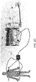
- Fig. 1 is a schematic, pictorial illustration of a catheter-based electrophysiological sensing system 20, in accordance with an embodiment of the present invention.
- System 20 may be, for example, a CARTO® 3 system, produced by Biosense-Webster, Irvine, California.
- system 20 comprises a catheter 21, having a shaft 22 that is navigated by a physician 30 into a heart 26 of a patient 28.
- physician 30 inserts shaft 22 through a sheath 23, while manipulating shaft 22 using a manipulator 32 near the proximal end of the catheter.
- catheter 21 may be used for any suitable diagnostic purpose, such as electrophysiological mapping of heart 26.
- An ECG recording instrument 35 may receive various types of ECG signals sensed by system 20 during the process.
- a distal end of shaft 22 of catheter 21 is fitted with a multi-electrode basket catheter 40.
- Inset 45 shows an arrangement of multiple sensing-electrodes 48 (i.e., 256 or more channels) of basket catheter 40.
- the proximal end of catheter 21 is connected by ADC dongle 50 to a control console 24.
- ADC dongle 50 accommodates extra channels from multiple electrodes 48 by digitizing all the catheter channels and transmitting the digitized signals to a digital link 51 of control console 24.
- Console 24 comprises a processor 41, typically a general-purpose computer, with suitable front end and interface circuits 38 for receiving ECG signals as well as non-ECG signals (such as position signals) from sensing-electrodes 48 of catheter 21. Electrodes 48 may include 256 or more sensing n electrodes and each electrode of electrode 48 will be referenced as "electrode 48 #1, #2, #3... #n" disposed inside or near the heart.
- processor 41 is connected to sensing electrodes 48 via wires running within shaft 22.
- Interface circuits 38 are further configured to receive ECG signals as well as non-ECG signals from surface body electrodes 49. Typically, electrodes 49 are attached to the skin around the chest and legs of patient 28. Processor 41 is connected to electrodes 49 by wires running through a cable 39 to receive signals from electrodes 49.
- a Wilson Central Terminal may be formed by three of the four named body surface electrodes 49, and a resulting ECG signal, V WCT , is received by interface circuits 38.
- system 20 has two of the catheter electrodes connected also to interface circuits 38 via a first split cable 52. In this way the legacy system directly receives the analog bipolar signal.
- the two aforementioned catheter electrodes provide the digital bipolar signal relative to a digital ground formed by a second spilt cable 54 electrically grounding one of the electrodes to a ground of dongle 50.
- Wirings 52 and 54 enable processor 41 of legacy system 20 to synchronize the two bipolar signals, and subsequently to accurately derive and present catheter unipolar ECG signals from electrodes 48 on legacy system 20, as described below.
- Processor 41 is typically programmed in software to carry out the functions described herein.
- the software may be downloaded to the processor in electronic form, over a network, for example, or it may, alternatively or additionally, be provided and/or stored on non-transitory tangible media, such as magnetic, optical, or electronic memory.
- processor 41 runs a dedicated algorithm as disclosed herein, included in Fig. 3 , that enables processor 41 to perform the disclosed steps, as further described below.
- Figs. 2A-2C are pictorial illustrations and an electrical diagram of an apparatus 100 that enables the system of Fig. 1 measuring unipolar signals from catheter 21, in accordance with an embodiment of the present invention.
- interface circuits 38 receive electrical signals from surface body electrodes 49 via cable 39. Electrodes 49 are typically attached to the patient skin around the chest and legs of patient 28. Four of electrodes 49 are shown: MA (right arm), LA (left arm), ML (right leg), LL (left leg). A Wilson Central Terminal (WCT) is formed by three of the four shown body surface electrodes 49, and a resulting ECG signal, V WCT , is received by interface circuits 38, as shown in Fig. 2B .
- WCT Wilson Central Terminal
- electrodes 48 #1 and #2 are wired by cable 52 into an input socket of interface circuits 38, which directly receives, in this way, an analog bipolar signal V 12 .
- any other two electrodes 48 of the 256 or more electrodes of catheter 21 may be used, and there is no loss of generality in using electrodes #1 and #2.
- All 256 or more of electrodes 48, also including electrodes #1 and #2, are connected to interface circuits 38 via dongle 50 that is plugged into a socket of digital link 51.
- electrode #1 is grounded inside dongle 50 via cable 54 to a ground of ADC dongle 50.
- FIG. 2C the schematic arrangement shown in Fig. 2A (for the CARTO® 3 system of Fig. 1 ) can be implemented with body surface sensors "BS" connected to the patient-interface-unit (PIU).
- the PIU is also connected to dongle 50 with the diagnostic catheter 48.
- both the circuit 38 and processor 41 are combined into the PIU.
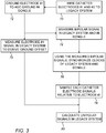
- Fig. 3 is a flow chart that schematically illustrates a method for measuring multiple unipolar signals from a catheter using the system of Fig. 1 , in accordance with an embodiment of the present invention.
- the algorithm according to the present embodiment carries out a process that begins with wiring catheter 21 electrode 48 #1 (i.e., the first electrode) and 48 electrode 48 #2 (e.g., from among the 256 electrodes of catheter 21) directly to interface circuits 38 of system 20 before signals from the two are digitized, at a first wiring step 70.
- electrode 48 #1 is grounded to a ground of ADC dongle 50.
- the analog potential of electrode 48 #1 is measured by interface circuits 38 and compared with the WCT potential to derive ground offset V 1 - V WCT .
- interface circuits 38 measure an analog bipolar signal and a digital bipolar signal that was digitalized from same source of the analog bipolar signal, at bipolar signals measurement step 76.
- interface circuits 38 synchronizes the clocks of system 20 and ADC dongle 50, at a clock synchronization step 76.
- catheter signals from each electrode are digitally sampled relative to electrode 48 #1, by ADC dongle 50.
- processor 41 calculates, using Eq. 1, a respective unipolar signal relative to the WCT ground.
Landscapes
- Health & Medical Sciences (AREA)
- Life Sciences & Earth Sciences (AREA)
- Engineering & Computer Science (AREA)
- Public Health (AREA)
- Biophysics (AREA)
- Pathology (AREA)
- Physics & Mathematics (AREA)
- Biomedical Technology (AREA)
- Heart & Thoracic Surgery (AREA)
- Medical Informatics (AREA)
- Molecular Biology (AREA)
- Surgery (AREA)
- Animal Behavior & Ethology (AREA)
- General Health & Medical Sciences (AREA)
- Veterinary Medicine (AREA)
- Cardiology (AREA)
- Physiology (AREA)
- Signal Processing (AREA)
- Artificial Intelligence (AREA)
- Computer Vision & Pattern Recognition (AREA)
- Psychiatry (AREA)
- Power Engineering (AREA)
- Measurement And Recording Of Electrical Phenomena And Electrical Characteristics Of The Living Body (AREA)
- Media Introduction/Drainage Providing Device (AREA)
- Ultra Sonic Daignosis Equipment (AREA)
- Pharmaceuticals Containing Other Organic And Inorganic Compounds (AREA)
- Materials For Medical Uses (AREA)
- Acyclic And Carbocyclic Compounds In Medicinal Compositions (AREA)
Abstract
Description
- This application claims the benefit of
U.S. Provisional Patent Application 62/863,679, filed June 19, 2019 - The present invention relates generally to the acquisition and processing of electrophysiological signals, and particularly the processing of electrocardiogram (ECG) signals acquired using a catheter.
- Electrocardiography (ECG) is a well-established cardiac diagnostic technique. Various techniques were proposed in the patent literature for measuring ECG signals. For example,
U.S. Patent 9,398,862 - As another example, Chinese Patent application Publication
2018/11333583 - A method includes receiving (i) an analog body-surface signal from one or more body-surface electrodes attached externally to a patient, and (ii) multiple analog unipolar signals from multiple unipolar electrodes of a probe inserted in an organ of the patient. A first unipolar electrode is assigned, from among the multiple unipolar electrodes, to serve as a common electrical ground and a common timing reference for the analog unipolar signals and the analog body-surface signal. The analog unipolar signals are digitized to produce respective digital unipolar signals by sampling the analog unipolar signals relative to a digital ground. The following are defined:(i) an analog bipolar signal between the first unipolar electrode and a second unipolar electrode of the probe and (ii) a digital bipolar signal formed from respective digital unipolar signals derived from the first unipolar electrode and the second unipolar electrode. A ground offset and a timing offset between the analog bipolar signal and the digital bipolar signal are estimated, while the first unipolar electrode is connected to the digital ground.
- The ground offset and the timing offset are applied in measuring a third unipolar signal, sensed by a third unipolar electrode of the catheter, relative to the body-surface signal.
- In some embodiments, the analog unipolar signals and the digital unipolar signals include electrocardiograms.
- In some embodiments, the analog body-surface signal includes a Wilson Central Terminal (WCT) signal.
- There is additionally provided, in accordance with another embodiment of the present invention, an apparatus including circuitry and a processor. The circuitry is configured to: (a) receive an analog body-surface signal from one or more body-surface electrodes attached externally to a patient, (b) receive multiple analog unipolar signals from multiple unipolar electrodes of a probe inserted in an organ of the patient, (c) assign, from among the multiple unipolar electrodes, a first unipolar electrode to serve as a common electrical ground and a common timing reference for the analog unipolar signals and the analog body-surface signal, (d) digitize the analog unipolar signals to produce respective digital unipolar signals by sampling the analog unipolar signals relative to a digital ground, and (e) define (i) an analog bipolar signal between the first unipolar electrode and a second unipolar electrode of the probe and (ii) a digital bipolar signal formed from respective digital unipolar signals derived from the first unipolar electrode and the second unipolar electrode. The processor is configured to estimate a ground offset and a timing offset between the analog bipolar signal and the digital bipolar signal, while the first unipolar electrode is connected to the digital ground, and apply the ground offset and the timing offset in measuring a third unipolar signal, sensed by a third unipolar electrode of the probe, relative to the body-surface signal.
- The present invention will be more fully understood from the following detailed description of the embodiments thereof, taken together with the drawings in which:
-
-
Fig. 1 is a schematic, pictorial illustration of a catheter-based electrophysiological sensing system, in accordance with an embodiment of the present invention; -
Figs. 2A-2C are pictorial illustrations and an electrical diagram of an apparatus that enables the system ofFig. 1 to measure unipolar signals from a catheter, in accordance with an embodiment of the present invention; and -
Fig. 3 is a flow chart that schematically illustrates a method for measuring multiple unipolar signals from a catheter using the system ofFig. 1 , in accordance with an embodiment of the present invention. - Legacy catheter-based cardiac systems are sometimes configured to measure a limited number of signals, e.g., up to several tens of electrocardiogram (ECG) channels. Modern diagnostic catheters, however, may have many more electrodes, e.g., 256 electrodes that are inside an organ (e.g., heart) of the subject. To accommodate the extra channels of modern diagnostic catheters, signals from such a catheter (e.g., a 256-channel basket catheter) may be transmitted to a legacy catheter-based system via a digital communication link, to process all of the channels.
- To have the analog signals from the catheter transmitted via the digital link, an analog to digital converter (ADC) module (referred to herein as an "ADC dongle" or simply "dongle") is inserted between the diagnostic catheter and the legacy catheter-based system.
- Some clinical applications require acquiring the catheter signals as unipolar signals relative to a Wilson Central Terminal (WCT) ground coupled to a legacy system, which is formed from three body surface electrodes attached to the skin of a patient. WCT ground is obtained by averaging the three external active limb electrode voltages measured with respect to the return ground electrode, which is further described in "True Unipolar ECG Machine for Wilson Central Terminal Measurements" by Gaetano D. Gargiulo, The MARCS Institute, University of Western Sydney, Kingswood, NSW2747, Australia, May 2015, and "Wilson's Central Terminal, the keystone to electrogram recording - What, where and why?" published April 23, 2013 by John Silberbauer, EP Fellow, San Raffaele Hospital, Milan, which are incorporated by reference in the Appendix.
- Two problems arise when the legacy system processor comes to derive and analyze unipolar signals relative to a WCT ground using the digitized signals from any of the internally disposed catheter's 256 ECG channels.
- The first problem is that the electrical ground of the ADC dongle, relative to which unipolar signals are digitized, and the ground of the legacy catheter-based system (e.g., WCT ground) are different. Therefore, the digitized unipolar amplitudes inputted from the catheter will have wrong amplitudes on the legacy catheter-based system.
- The second problem is that the timing (e.g., signal phase) of the digitized signals and the timing of the WCT ground of the legacy catheter-based system are unrelated. The desynchronized signals (digitized catheter signals vs. analog ground signals) cannot thus be related one to the other (even if there were no issue of ground amplitude).
- Embodiments of the present invention that are described hereinafter provide apparatuses and methods to overcome the lack of common ground and lack of signal synchronization described above between a legacy system and a modern diagnostic catheter coupled via a digital link. The disclosed techniques enable, for example, accurate measurement of multiple unipolar ECG signals using a legacy system.
- In some embodiments, a disclosed apparatus is provided in order to overcome the lack of common ground and lack of signal synchronization described above. The apparatus comprises interface circuitry of the legacy system, which is configured to receive an analog body-surface signal from one or more body-surface electrodes attached externally to the patient (e.g., a WCT ground signal).
- The disclosed apparatus further comprises an additional (e.g., an add-on or a stand-alone) circuitry comprising an ADC module, wherein the additional circuitry is configured to receive multiple analog unipolar signals from multiple unipolar electrodes of a probe inserted in an organ of the patient, assign, from among the multiple unipolar electrodes, a first unipolar electrode to serve as a common electrical ground and a common timing reference for the analog unipolar signals and the analog body-surface signal, digitize the analog unipolar signals to produce respective digital unipolar signals by sampling the analog unipolar signals relative to a digital ground, and define (i) an analog bipolar signal between the first unipolar electrode and a second unipolar electrode of the probe and (ii) a digital bipolar signal formed from respective digital unipolar signals derived from the first unipolar electrode and the second unipolar electrode.
- The disclosed apparatus further comprises a processor of the legacy system that is configured to estimate a ground offset and a timing offset between the analog bipolar signal and the digital bipolar signal, while the first unipolar electrode is connected to the digital ground, and apply the ground offset and the timing offset in measuring a third unipolar signal, sensed by a third unipolar electrode of the probe (e.g., catheter), relative to the body-surface signal.
- In other words, the disclosed technique sacrifices one of the electrodes of the probe, and uses this electrode to serve as a common ground and a common timing reference between the digitized signals and for the original analog signals.
- To estimate the timing offset, the processor of the legacy system commands the interface circuitry to apply high-pass filtering (i.e., "skews") to both the analog bipolar signal input and the digital bipolar signals. The two bipolar signals are then routed into a cross-correlator circuit of the legacy system that cross-correlates the two bipolar signals. In an embodiment, using the cross-correlated bipolar signals, the processor synchronizes the clocks of the legacy system and the dongle signals to cancel the timing offset between the analog and digital bipolar signals.
- To apply the ground offset in measuring the third unipolar signal, after the timing offset was applied, , the processor of the legacy system calculate a respective unipolar signal acquired by the third electrode of the probe. The processor can calculate the unipolar voltage by calculating from any third catheter electrode X, the value of V x-V WCT, X=1, 2, ..., 256, i.e., for a digitized signal from any catheter electrode which is transmitted via the digital link, as described below.
- Typically, the processor is programmed in software containing a particular algorithm that enables the processor to conduct each of the processor related steps and functions outlined above.
- The disclosed technique provides a simple and effective means to enable the legacy system to accurately measure multiple unipolar signals acquired by multiple electrodes of a modern catheter. Thus, the disclosed technique may increase the availability of modern catheter-based diagnostic services.
-
Fig. 1 is a schematic, pictorial illustration of a catheter-basedelectrophysiological sensing system 20, in accordance with an embodiment of the present invention.System 20 may be, for example, a CARTO® 3 system, produced by Biosense-Webster, Irvine, California. As seen,system 20 comprises acatheter 21, having ashaft 22 that is navigated by aphysician 30 into aheart 26 of apatient 28. In the pictured example,physician 30inserts shaft 22 through asheath 23, while manipulatingshaft 22 using amanipulator 32 near the proximal end of the catheter. - In the embodiment described herein,
catheter 21 may be used for any suitable diagnostic purpose, such as electrophysiological mapping ofheart 26. AnECG recording instrument 35 may receive various types of ECG signals sensed bysystem 20 during the process. - As shown in
inset 25, a distal end ofshaft 22 ofcatheter 21 is fitted with amulti-electrode basket catheter 40. Inset 45 shows an arrangement of multiple sensing-electrodes 48 (i.e., 256 or more channels) ofbasket catheter 40. The proximal end ofcatheter 21 is connected byADC dongle 50 to acontrol console 24.ADC dongle 50 accommodates extra channels frommultiple electrodes 48 by digitizing all the catheter channels and transmitting the digitized signals to adigital link 51 ofcontrol console 24. -
Console 24 comprises aprocessor 41, typically a general-purpose computer, with suitable front end andinterface circuits 38 for receiving ECG signals as well as non-ECG signals (such as position signals) from sensing-electrodes 48 ofcatheter 21.Electrodes 48 may include 256 or more sensing n electrodes and each electrode ofelectrode 48 will be referenced as "electrode 48 #1, #2, #3... #n" disposed inside or near the heart. For this purpose,processor 41 is connected to sensingelectrodes 48 via wires running withinshaft 22.Interface circuits 38 are further configured to receive ECG signals as well as non-ECG signals fromsurface body electrodes 49. Typically,electrodes 49 are attached to the skin around the chest and legs ofpatient 28.Processor 41 is connected toelectrodes 49 by wires running through acable 39 to receive signals fromelectrodes 49. - Four of
surface body electrodes 49 are named according to standard ECG protocols: MA (right arm), LA (left arm), ML (right leg), and LL (left leg). A Wilson Central Terminal (WCT) may be formed by three of the four namedbody surface electrodes 49, and a resulting ECG signal, V WCT, is received byinterface circuits 38. - To overcome the above described lack of synchronization between signals acquired by
catheter electrodes 48 andsurface body electrodes 49,system 20 has two of the catheter electrodes connected also to interfacecircuits 38 via afirst split cable 52. In this way the legacy system directly receives the analog bipolar signal. In addition, the two aforementioned catheter electrodes provide the digital bipolar signal relative to a digital ground formed by a second spiltcable 54 electrically grounding one of the electrodes to a ground ofdongle 50. Wirings 52 and 54 enableprocessor 41 oflegacy system 20 to synchronize the two bipolar signals, and subsequently to accurately derive and present catheter unipolar ECG signals fromelectrodes 48 onlegacy system 20, as described below. -
Processor 41 is typically programmed in software to carry out the functions described herein. The software may be downloaded to the processor in electronic form, over a network, for example, or it may, alternatively or additionally, be provided and/or stored on non-transitory tangible media, such as magnetic, optical, or electronic memory. In particular,processor 41 runs a dedicated algorithm as disclosed herein, included inFig. 3 , that enablesprocessor 41 to perform the disclosed steps, as further described below. -
Figs. 2A-2C are pictorial illustrations and an electrical diagram of anapparatus 100 that enables the system ofFig. 1 measuring unipolar signals fromcatheter 21, in accordance with an embodiment of the present invention. - As seen in
Fig. 2A ,interface circuits 38 receive electrical signals fromsurface body electrodes 49 viacable 39.Electrodes 49 are typically attached to the patient skin around the chest and legs ofpatient 28. Four ofelectrodes 49 are shown: MA (right arm), LA (left arm), ML (right leg), LL (left leg). A Wilson Central Terminal (WCT) is formed by three of the four shownbody surface electrodes 49, and a resulting ECG signal, V WCT, is received byinterface circuits 38, as shown inFig. 2B . - As further seen in
Fig. 2B ,electrodes 48 #1 and #2 are wired bycable 52 into an input socket ofinterface circuits 38, which directly receives, in this way, an analog bipolar signal V12 . Note that any other twoelectrodes 48 of the 256 or more electrodes ofcatheter 21 may be used, and there is no loss of generality in usingelectrodes # 1 and #2. All 256 or more ofelectrodes 48, also includingelectrodes # 1 and #2, are connected to interfacecircuits 38 viadongle 50 that is plugged into a socket ofdigital link 51. As seen,electrode # 1 is grounded insidedongle 50 viacable 54 to a ground ofADC dongle 50. -
Processor 41 receives, viaADC dongle 50 viadigital link 51 ininterface circuits 38, an input set of signals comprising the set of measured and digitized bipolar signals, (V x-V 1), X=2, ..., n where n is 256 or more.Processor 41 further directly receives, viainterface circuits 38, a measured ground offset signal (V 1-V WCT) that the processor can now add to the synchronized digitized signals bipolar signals, (V x-V 1) to derive unipolar signals.Processor 41 derives each of the remining 255 unipolar signals V x-V WCT, (i.e., relative to V WCT) by calculating the following additive calculation:
- As shown in
Fig. 2C , the schematic arrangement shown inFig. 2A (for the CARTO® 3 system ofFig. 1 ) can be implemented with body surface sensors "BS" connected to the patient-interface-unit (PIU). The PIU is also connected to dongle 50 with thediagnostic catheter 48. In this prototype, both thecircuit 38 andprocessor 41 are combined into the PIU. -
Fig. 3 is a flow chart that schematically illustrates a method for measuring multiple unipolar signals from a catheter using the system ofFig. 1 , in accordance with an embodiment of the present invention. The algorithm according to the present embodiment carries out a process that begins withwiring catheter 21electrode 48 #1 (i.e., the first electrode) and 48electrode 48 #2 (e.g., from among the 256 electrodes of catheter 21) directly to interfacecircuits 38 ofsystem 20 before signals from the two are digitized, at afirst wiring step 70. At asecond wiring step 72,electrode 48 #1 is grounded to a ground ofADC dongle 50. - At a ground offset
extraction step 73, the analog potential ofelectrode 48 #1 is measured byinterface circuits 38 and compared with the WCT potential to derive ground offset V 1-V WCT. - In parallel,
interface circuits 38 measure an analog bipolar signal and a digital bipolar signal that was digitalized from same source of the analog bipolar signal, at bipolarsignals measurement step 76. - Using the measured analog and digital bipolar signals,
interface circuits 38 synchronizes the clocks ofsystem 20 andADC dongle 50, at aclock synchronization step 76. - At a
sampling step 78, catheter signals from each electrode are digitally sampled relative to electrode 48 #1, byADC dongle 50. - Finally, at a unipolar
signal calculation step 80, for a third digitized signal from anyelectrode 48 different thanelectrodes 48 #1 and #2,processor 41 calculates, using Eq. 1, a respective unipolar signal relative to the WCT ground. - The example configurations shown in the figures are chosen purely for the sake of conceptual clarity. In alternative embodiments, the disclosed techniques may use other suitable configurations comprising other wiring schemes, different standalone interfaces, and other types of catheters than a basket catheter.
- It will be appreciated that the embodiments described above are cited by way of example, and that the present invention is not limited to what has been particularly shown and described hereinabove. Rather, the scope of the present invention includes both combinations and subcombinations of the various features described hereinabove, as well as variations and modifications thereof which would occur to persons skilled in the art upon reading the foregoing description and which are not disclosed in the prior art. Documents incorporated by reference in the present patent application are to be considered an integral part of the application except that to the extent any terms are defined in these incorporated documents in a manner that conflicts with the definitions made explicitly or implicitly in the present specification, only the definitions in the present specification should be considered.
Claims (8)
- A method, comprising:receiving (i) an analog body-surface signal from one or more body-surface electrodes attached externally to a patient, and (ii) multiple analog unipolar signals from multiple unipolar electrodes of a probe inserted in an organ of the patient;assigning, from among the multiple unipolar electrodes, a first unipolar electrode to serve as a common electrical ground and a common timing reference for the analog unipolar signals and the analog body-surface signal;digitizing the analog unipolar signals to produce respective digital unipolar signals by sampling the analog unipolar signals relative to a digital ground;defining (i) an analog bipolar signal between the first unipolar electrode and a second unipolar electrode of the probe and (ii) a digital bipolar signal formed from respective digital unipolar signals derived from the first unipolar electrode and the second unipolar electrode;estimating a ground offset and a timing offset between the analog bipolar signal and the digital bipolar signal, while the first unipolar electrode is connected to the digital ground; andapplying the ground offset and the timing offset in measuring a third unipolar signal, sensed by a third unipolar electrode of the probe, relative to the body-surface signal.
- The method according to claim 1, wherein the analog unipolar signals and the digital unipolar signals comprise electrocardiograms.
- The method according to claim 1, wherein the analog body-surface signal comprises a Wilson Central Terminal (WCT) signal.
- An apparatus, comprising:circuitry, which is configured to:receive an analog body-surface signal from one or more body-surface electrodes attached externally to a patient;receive multiple analog unipolar signals from multiple unipolar electrodes of a probe inserted in an organ of the patient;assign, from among the multiple unipolar electrodes, a first unipolar electrode to serve as a common electrical ground and a common timing reference for the analog unipolar signals and the analog body-surface signal;digitize the analog unipolar signals to produce respective digital unipolar signals by sampling the analog unipolar signals relative to a digital ground;and
define (i) an analog bipolar signal between the first unipolar electrode and a second unipolar electrode of the probe and (ii) a digital bipolar signal formed from respective digital unipolar signals derived from the first unipolar electrode and the second unipolar electrode; anda processor, which is configured to:estimate a ground offset and a timing offset between the analog bipolar signal and the digital bipolar signal, while the first unipolar electrode is connected to the digital ground; andapply the ground offset and the timing offset in measuring a third unipolar signal, sensed by a third unipolar electrode of the probe, relative to the body-surface signal. - The apparatus according to claim 4, wherein the interface circuitry and the processor are included in a legacy system.
- The apparatus according to claim 4, wherein the analog unipolar signals and the digital unipolar signals comprise electrocardiograms.
- The apparatus according to claim 4, wherein the analog body-surface signal comprises a Wilson Central Terminal (WCT) signal.
- The apparatus according to claim 4, wherein the interface circuitry comprises a multi-channel digital link configured to receive digitized signals from the probe.
Applications Claiming Priority (2)
| Application Number | Priority Date | Filing Date | Title |
|---|---|---|---|
| US201962863679P | 2019-06-19 | 2019-06-19 | |
| US16/817,545 US11504042B2 (en) | 2019-06-19 | 2020-03-12 | Extension of electrocardiography (ECG) acquisition capabilities of catheter-based cardiac system |
Publications (2)
| Publication Number | Publication Date |
|---|---|
| EP3753479A1 true EP3753479A1 (en) | 2020-12-23 |
| EP3753479B1 EP3753479B1 (en) | 2022-07-13 |
Family
ID=71108396
Family Applications (1)
| Application Number | Title | Priority Date | Filing Date |
|---|---|---|---|
| EP20180660.1A Active EP3753479B1 (en) | 2019-06-19 | 2020-06-18 | Extension of electrocardiography (ecg) acquisition capabilities of catheter-based cardiac system |
Country Status (5)
| Country | Link |
|---|---|
| US (2) | US11504042B2 (en) |
| EP (1) | EP3753479B1 (en) |
| JP (1) | JP7686376B2 (en) |
| CN (1) | CN112315475B (en) |
| IL (1) | IL275215B2 (en) |
Families Citing this family (38)
| Publication number | Priority date | Publication date | Assignee | Title |
|---|---|---|---|---|
| US10905329B2 (en) | 2016-06-09 | 2021-02-02 | Biosense Webster (Israel) Ltd. | Multi-function conducting elements for a catheter |
| US12029545B2 (en) | 2017-05-30 | 2024-07-09 | Biosense Webster (Israel) Ltd. | Catheter splines as location sensors |
| US20190314083A1 (en) | 2018-04-11 | 2019-10-17 | Biosense Webster (Israel) Ltd. | Flexible Multi-Arm Catheter with Diametrically Opposed Sensing Electrodes |
| US11045628B2 (en) | 2018-12-11 | 2021-06-29 | Biosense Webster (Israel) Ltd. | Balloon catheter with high articulation |
| US11207016B2 (en) | 2018-12-28 | 2021-12-28 | Biosense Webster (Israel) Ltd. | Mapping ECG signals using a multipole electrode assembly |
| US11850051B2 (en) | 2019-04-30 | 2023-12-26 | Biosense Webster (Israel) Ltd. | Mapping grid with high density electrode array |
| US11712172B2 (en) | 2019-07-18 | 2023-08-01 | Biosense Webster (Israel) Ltd. | Visual guidance for positioning a distal end of a medical probe |
| US11759150B2 (en) | 2019-08-27 | 2023-09-19 | Biosense Webster (Israel) Ltd. | Accurate basket catheter tracking |
| US11950930B2 (en) | 2019-12-12 | 2024-04-09 | Biosense Webster (Israel) Ltd. | Multi-dimensional acquisition of bipolar signals from a catheter |
| US11517218B2 (en) | 2019-12-20 | 2022-12-06 | Biosense Webster (Israel) Ltd. | Selective graphical presentation of electrophysiological parameters |
| US12232874B2 (en) | 2020-05-29 | 2025-02-25 | Biosense Webster (Israel) Ltd. | Electrode apparatus for diagnosis of arrhythmias |
| US11987017B2 (en) | 2020-06-08 | 2024-05-21 | Biosense Webster (Israel) Ltd. | Features to assist in assembly and testing of devices |
| US11406308B2 (en) * | 2020-07-14 | 2022-08-09 | Biosense Webster (Israel) Ltd. | Visualization and recordation system interface with virtual ground for biomedical system and methods |
| US12048479B2 (en) | 2020-09-10 | 2024-07-30 | Biosense Webster (Israel) Ltd. | Surface mounted electrode catheter |
| US11950840B2 (en) | 2020-09-22 | 2024-04-09 | Biosense Webster (Israel) Ltd. | Basket catheter having insulated ablation electrodes |
| US11950841B2 (en) | 2020-09-22 | 2024-04-09 | Biosense Webster (Israel) Ltd. | Basket catheter having insulated ablation electrodes and diagnostic electrodes |
| US12082875B2 (en) | 2020-09-24 | 2024-09-10 | Biosense Webster (Israel) Ltd | Balloon catheter having a coil for sensing tissue temperature and position of the balloon |
| US11974803B2 (en) | 2020-10-12 | 2024-05-07 | Biosense Webster (Israel) Ltd. | Basket catheter with balloon |
| US12201786B2 (en) | 2020-12-17 | 2025-01-21 | Biosense Webster (Israel) Ltd. | Measurement of distal end dimension of catheters using magnetic fields |
| US11918383B2 (en) | 2020-12-21 | 2024-03-05 | Biosense Webster (Israel) Ltd. | Visualizing performance of catheter electrodes |
| US12064170B2 (en) | 2021-05-13 | 2024-08-20 | Biosense Webster (Israel) Ltd. | Distal assembly for catheter with lumens running along spines |
| US12364426B2 (en) | 2021-08-12 | 2025-07-22 | Biosense Webster (Israel) Ltd. | Electro-anatomical mapping and annotation presented in electrophysiological procedures |
| US12004804B2 (en) | 2021-09-09 | 2024-06-11 | Biosense Webster (Israel) Ltd. | Basket catheter with mushroom shape distal tip |
| US12478424B2 (en) | 2021-09-10 | 2025-11-25 | Biosense Webster (Israel) Ltd. | Staggered pairs of biased ablation electrodes on basket catheter |
| US12011280B2 (en) | 2021-10-04 | 2024-06-18 | Biosense Webster (Israel) Ltd. | Electrophysiological mapping in the presence of injury current |
| US12533489B2 (en) | 2021-10-08 | 2026-01-27 | Biosense Webster (Israel) Ltd. | Measuring tissue proximity for multi-electrode catheter |
| US12419683B2 (en) | 2021-12-22 | 2025-09-23 | Biosense Webster (Israel) Ltd. | Irreversible electroporation with shorted electrodes |
| US12440263B2 (en) | 2022-01-20 | 2025-10-14 | Biosense Webster (Israel) Ltd. | Systems and methods for tripodic spines forming a spherical basket for improved tissue contact and current delivery |
| US12446946B2 (en) | 2022-01-20 | 2025-10-21 | Biosense Webster (Israel) Ltd. | Systems and methods for a single spiral electrode assembly forming a spherical basket for improved tissue contact and current delivery |
| US12484961B2 (en) | 2022-01-20 | 2025-12-02 | Biosense Webster (Israel) Ltd. | Mechanical retainer systems for electrodes of a basket catheter, and methods of the same |
| US12616517B2 (en) | 2022-03-25 | 2026-05-05 | Biosense Webster (Israel) Ltd. | Expandable basket assemblies with linear spine patterns for improved tissue contact and methods for making thereof |
| US12471989B2 (en) | 2022-04-28 | 2025-11-18 | Biosense Webster (Israel) Ltd. | Strengthened expandable baskets for medical probes and medical probes containing strengthen expandable baskets |
| US12616518B2 (en) | 2022-04-28 | 2026-05-05 | Biosense Webster (Israel) Ltd. | Barrel electrodes for a basket catheter, and methods of the same |
| CN115956919B (en) * | 2022-12-07 | 2023-11-17 | 上海类比半导体技术有限公司 | Offset self-calibration circuit, method, chip and system |
| US12616519B2 (en) | 2022-12-15 | 2026-05-05 | Biosense Webster (Israel) Ltd. | Basket assembly with atraumatic tip electrode and methods of making thereof |
| US12533185B2 (en) | 2022-12-28 | 2026-01-27 | Biosense Webster (Israel) Ltd. | Basket end effector with distal position sensor |
| US12521035B2 (en) | 2022-12-29 | 2026-01-13 | Biosense Webster (Israel) Ltd. | Cylindrical cage systems and methods for distributed tissue contact for mapping and ablation |
| US20240423555A1 (en) * | 2023-06-23 | 2024-12-26 | Biosense Webster (Israel) Ltd. | System and Method of Synchronization of Biopotential Signals |
Citations (5)
| Publication number | Priority date | Publication date | Assignee | Title |
|---|---|---|---|---|
| US5764541A (en) * | 1995-12-22 | 1998-06-09 | Hermann Finance Corporation Ltd. | Microprocessor controlled sensor signal conditioning circuit |
| WO2001014001A1 (en) * | 1999-08-20 | 2001-03-01 | Cardiac Pacemakers, Inc. | Cardiac rhythm management system with differential sensing channel |
| US20040097813A1 (en) * | 2002-11-19 | 2004-05-20 | Jonathan Williams | Method and device for correcting in -vivo sensor drift |
| US9398862B2 (en) | 2009-04-23 | 2016-07-26 | Rhythmia Medical, Inc. | Multi-electrode mapping system |
| EP3320838A1 (en) * | 2016-11-14 | 2018-05-16 | Biosense Webster (Israel) Ltd. | Asic with switching noise reduction |
Family Cites Families (7)
| Publication number | Priority date | Publication date | Assignee | Title |
|---|---|---|---|---|
| CA2337240C (en) * | 1998-07-16 | 2011-01-25 | Universite De Montreal | Disturbance-free electromyographic probe |
| US20070078353A1 (en) | 2005-10-04 | 2007-04-05 | Welch Allyn, Inc. | Method and apparatus for removing baseline wander from an ECG signal |
| US9005193B2 (en) * | 2010-11-08 | 2015-04-14 | Biosense Webster (Israel) Ltd. | Multichannel ablation with frequency differentiation |
| JP2018514279A (en) | 2015-05-08 | 2018-06-07 | セント・ジュード・メディカル,カーディオロジー・ディヴィジョン,インコーポレイテッド | System and method for real-time electrophysiological mapping |
| US10905329B2 (en) | 2016-06-09 | 2021-02-02 | Biosense Webster (Israel) Ltd. | Multi-function conducting elements for a catheter |
| US10645017B2 (en) * | 2018-05-09 | 2020-05-05 | Biosig Technologies, Inc. | Systems, apparatus, and methods for conveying biomedical signals between a patient and monitoring and treatment devices |
| CN109222941A (en) | 2018-11-09 | 2019-01-18 | 中科数字健康科学研究院(南京)有限公司 | A kind of measurement method and measuring device of pulse wave propagation time |
-
2020
- 2020-03-12 US US16/817,545 patent/US11504042B2/en active Active
- 2020-06-08 IL IL275215A patent/IL275215B2/en unknown
- 2020-06-18 JP JP2020105211A patent/JP7686376B2/en active Active
- 2020-06-18 EP EP20180660.1A patent/EP3753479B1/en active Active
- 2020-06-19 CN CN202010564440.5A patent/CN112315475B/en active Active
-
2022
- 2022-10-31 US US17/977,156 patent/US20230052985A1/en active Pending
Patent Citations (5)
| Publication number | Priority date | Publication date | Assignee | Title |
|---|---|---|---|---|
| US5764541A (en) * | 1995-12-22 | 1998-06-09 | Hermann Finance Corporation Ltd. | Microprocessor controlled sensor signal conditioning circuit |
| WO2001014001A1 (en) * | 1999-08-20 | 2001-03-01 | Cardiac Pacemakers, Inc. | Cardiac rhythm management system with differential sensing channel |
| US20040097813A1 (en) * | 2002-11-19 | 2004-05-20 | Jonathan Williams | Method and device for correcting in -vivo sensor drift |
| US9398862B2 (en) | 2009-04-23 | 2016-07-26 | Rhythmia Medical, Inc. | Multi-electrode mapping system |
| EP3320838A1 (en) * | 2016-11-14 | 2018-05-16 | Biosense Webster (Israel) Ltd. | Asic with switching noise reduction |
Non-Patent Citations (2)
| Title |
|---|
| GAETANO D. GARGIULO: "True Unipolar ECG Machine for Wilson Central Terminal Measurements", May 2015, THE MARCS INSTITUTE, UNIVERSITY OF WESTERN SYDNEY |
| JOHN SILBERBAUER: "Wilson's Central Terminal, the keystone to electrogram recording - What, where and why?", 23 April 2013, SAN RAFFAELE HOSPITAL |
Also Published As
| Publication number | Publication date |
|---|---|
| US20200397328A1 (en) | 2020-12-24 |
| US20230052985A1 (en) | 2023-02-16 |
| US11504042B2 (en) | 2022-11-22 |
| CN112315475A (en) | 2021-02-05 |
| IL275215A (en) | 2020-12-31 |
| IL275215B1 (en) | 2023-04-01 |
| CN112315475B (en) | 2025-06-03 |
| JP2021000445A (en) | 2021-01-07 |
| IL275215B2 (en) | 2023-08-01 |
| JP7686376B2 (en) | 2025-06-02 |
| EP3753479B1 (en) | 2022-07-13 |
Similar Documents
| Publication | Publication Date | Title |
|---|---|---|
| EP3753479B1 (en) | Extension of electrocardiography (ecg) acquisition capabilities of catheter-based cardiac system | |
| US11596324B2 (en) | Combined active current location (ACL) and tissue proximity indication (TPI) system | |
| JP6234795B2 (en) | Multi-channel ECG measurement | |
| CN107666856A (en) | Magnetic Sensing Provides Geometry Information | |
| EP3662825A1 (en) | Coronary sinus (cs) catheter movement detection | |
| EP3777659A1 (en) | Electroanatomical map re-annotation | |
| EP3449816B1 (en) | Medical system comprising a patch for simultaneously sensing ecg signals and impedance-indicative electrical signals | |
| RU2422084C2 (en) | Device for watching electrodes inside patient's body and method of its realisation | |
| EP3583895A1 (en) | Identifying orthogonal sets of active current location (acl) patches | |
| EP3656301B1 (en) | Compensating for artifacts while tracking an intrabody probe | |
| EP3607882B1 (en) | Reducing capacitance effects in active current location (acl) | |
| US20250090043A1 (en) | System and Method of Synchronization of Location Signals | |
| CN110623656A (en) | Improve signal quality in multiplexed systems by actively disconnecting unused connections | |
| CN121622275A (en) | Systems and methods for position sensing |
Legal Events
| Date | Code | Title | Description |
|---|---|---|---|
| PUAI | Public reference made under article 153(3) epc to a published international application that has entered the european phase |
Free format text: ORIGINAL CODE: 0009012 |
|
| STAA | Information on the status of an ep patent application or granted ep patent |
Free format text: STATUS: THE APPLICATION HAS BEEN PUBLISHED |
|
| AK | Designated contracting states |
Kind code of ref document: A1 Designated state(s): AL AT BE BG CH CY CZ DE DK EE ES FI FR GB GR HR HU IE IS IT LI LT LU LV MC MK MT NL NO PL PT RO RS SE SI SK SM TR |
|
| AX | Request for extension of the european patent |
Extension state: BA ME |
|
| STAA | Information on the status of an ep patent application or granted ep patent |
Free format text: STATUS: REQUEST FOR EXAMINATION WAS MADE |
|
| 17P | Request for examination filed |
Effective date: 20210513 |
|
| RBV | Designated contracting states (corrected) |
Designated state(s): AL AT BE BG CH CY CZ DE DK EE ES FI FR GB GR HR HU IE IS IT LI LT LU LV MC MK MT NL NO PL PT RO RS SE SI SK SM TR |
|
| GRAP | Despatch of communication of intention to grant a patent |
Free format text: ORIGINAL CODE: EPIDOSNIGR1 |
|
| STAA | Information on the status of an ep patent application or granted ep patent |
Free format text: STATUS: GRANT OF PATENT IS INTENDED |
|
| RIC1 | Information provided on ipc code assigned before grant |
Ipc: H03M 1/52 20060101ALN20210929BHEP Ipc: A61B 5/333 20210101ALI20210929BHEP Ipc: A61B 5/30 20210101ALI20210929BHEP Ipc: A61B 5/287 20210101ALI20210929BHEP Ipc: A61B 5/282 20210101ALI20210929BHEP Ipc: H03M 1/12 20060101ALI20210929BHEP Ipc: A61B 5/00 20060101AFI20210929BHEP |
|
| INTG | Intention to grant announced |
Effective date: 20211022 |
|
| GRAJ | Information related to disapproval of communication of intention to grant by the applicant or resumption of examination proceedings by the epo deleted |
Free format text: ORIGINAL CODE: EPIDOSDIGR1 |
|
| STAA | Information on the status of an ep patent application or granted ep patent |
Free format text: STATUS: REQUEST FOR EXAMINATION WAS MADE |
|
| GRAP | Despatch of communication of intention to grant a patent |
Free format text: ORIGINAL CODE: EPIDOSNIGR1 |
|
| STAA | Information on the status of an ep patent application or granted ep patent |
Free format text: STATUS: GRANT OF PATENT IS INTENDED |
|
| INTC | Intention to grant announced (deleted) | ||
| RIC1 | Information provided on ipc code assigned before grant |
Ipc: H03M 1/52 20060101ALN20220126BHEP Ipc: A61B 5/333 20210101ALI20220126BHEP Ipc: A61B 5/30 20210101ALI20220126BHEP Ipc: A61B 5/287 20210101ALI20220126BHEP Ipc: A61B 5/282 20210101ALI20220126BHEP Ipc: H03M 1/12 20060101ALI20220126BHEP Ipc: A61B 5/00 20060101AFI20220126BHEP |
|
| INTG | Intention to grant announced |
Effective date: 20220302 |
|
| RIC1 | Information provided on ipc code assigned before grant |
Ipc: H03M 1/52 20060101ALN20220218BHEP Ipc: A61B 5/333 20210101ALI20220218BHEP Ipc: A61B 5/30 20210101ALI20220218BHEP Ipc: A61B 5/287 20210101ALI20220218BHEP Ipc: A61B 5/282 20210101ALI20220218BHEP Ipc: H03M 1/12 20060101ALI20220218BHEP Ipc: A61B 5/00 20060101AFI20220218BHEP |
|
| GRAS | Grant fee paid |
Free format text: ORIGINAL CODE: EPIDOSNIGR3 |
|
| GRAA | (expected) grant |
Free format text: ORIGINAL CODE: 0009210 |
|
| STAA | Information on the status of an ep patent application or granted ep patent |
Free format text: STATUS: THE PATENT HAS BEEN GRANTED |
|
| RAP3 | Party data changed (applicant data changed or rights of an application transferred) |
Owner name: BIOSENSE WEBSTER (ISRAEL) LTD. |
|
| AK | Designated contracting states |
Kind code of ref document: B1 Designated state(s): AL AT BE BG CH CY CZ DE DK EE ES FI FR GB GR HR HU IE IS IT LI LT LU LV MC MK MT NL NO PL PT RO RS SE SI SK SM TR |
|
| REG | Reference to a national code |
Ref country code: CH Ref legal event code: EP |
|
| REG | Reference to a national code |
Ref country code: DE Ref legal event code: R096 Ref document number: 602020003963 Country of ref document: DE |
|
| REG | Reference to a national code |
Ref country code: AT Ref legal event code: REF Ref document number: 1503854 Country of ref document: AT Kind code of ref document: T Effective date: 20220815 |
|
| REG | Reference to a national code |
Ref country code: IE Ref legal event code: FG4D |
|
| REG | Reference to a national code |
Ref country code: NL Ref legal event code: FP |
|
| REG | Reference to a national code |
Ref country code: LT Ref legal event code: MG9D |
|
| PG25 | Lapsed in a contracting state [announced via postgrant information from national office to epo] |
Ref country code: SE Free format text: LAPSE BECAUSE OF FAILURE TO SUBMIT A TRANSLATION OF THE DESCRIPTION OR TO PAY THE FEE WITHIN THE PRESCRIBED TIME-LIMIT Effective date: 20220713 Ref country code: RS Free format text: LAPSE BECAUSE OF FAILURE TO SUBMIT A TRANSLATION OF THE DESCRIPTION OR TO PAY THE FEE WITHIN THE PRESCRIBED TIME-LIMIT Effective date: 20220713 Ref country code: PT Free format text: LAPSE BECAUSE OF FAILURE TO SUBMIT A TRANSLATION OF THE DESCRIPTION OR TO PAY THE FEE WITHIN THE PRESCRIBED TIME-LIMIT Effective date: 20221114 Ref country code: NO Free format text: LAPSE BECAUSE OF FAILURE TO SUBMIT A TRANSLATION OF THE DESCRIPTION OR TO PAY THE FEE WITHIN THE PRESCRIBED TIME-LIMIT Effective date: 20221013 Ref country code: LV Free format text: LAPSE BECAUSE OF FAILURE TO SUBMIT A TRANSLATION OF THE DESCRIPTION OR TO PAY THE FEE WITHIN THE PRESCRIBED TIME-LIMIT Effective date: 20220713 Ref country code: LT Free format text: LAPSE BECAUSE OF FAILURE TO SUBMIT A TRANSLATION OF THE DESCRIPTION OR TO PAY THE FEE WITHIN THE PRESCRIBED TIME-LIMIT Effective date: 20220713 Ref country code: FI Free format text: LAPSE BECAUSE OF FAILURE TO SUBMIT A TRANSLATION OF THE DESCRIPTION OR TO PAY THE FEE WITHIN THE PRESCRIBED TIME-LIMIT Effective date: 20220713 Ref country code: ES Free format text: LAPSE BECAUSE OF FAILURE TO SUBMIT A TRANSLATION OF THE DESCRIPTION OR TO PAY THE FEE WITHIN THE PRESCRIBED TIME-LIMIT Effective date: 20220713 |
|
| REG | Reference to a national code |
Ref country code: AT Ref legal event code: MK05 Ref document number: 1503854 Country of ref document: AT Kind code of ref document: T Effective date: 20220713 |
|
| PG25 | Lapsed in a contracting state [announced via postgrant information from national office to epo] |
Ref country code: PL Free format text: LAPSE BECAUSE OF FAILURE TO SUBMIT A TRANSLATION OF THE DESCRIPTION OR TO PAY THE FEE WITHIN THE PRESCRIBED TIME-LIMIT Effective date: 20220713 Ref country code: IS Free format text: LAPSE BECAUSE OF FAILURE TO SUBMIT A TRANSLATION OF THE DESCRIPTION OR TO PAY THE FEE WITHIN THE PRESCRIBED TIME-LIMIT Effective date: 20221113 Ref country code: HR Free format text: LAPSE BECAUSE OF FAILURE TO SUBMIT A TRANSLATION OF THE DESCRIPTION OR TO PAY THE FEE WITHIN THE PRESCRIBED TIME-LIMIT Effective date: 20220713 Ref country code: GR Free format text: LAPSE BECAUSE OF FAILURE TO SUBMIT A TRANSLATION OF THE DESCRIPTION OR TO PAY THE FEE WITHIN THE PRESCRIBED TIME-LIMIT Effective date: 20221014 |
|
| REG | Reference to a national code |
Ref country code: DE Ref legal event code: R097 Ref document number: 602020003963 Country of ref document: DE |
|
| PG25 | Lapsed in a contracting state [announced via postgrant information from national office to epo] |
Ref country code: SM Free format text: LAPSE BECAUSE OF FAILURE TO SUBMIT A TRANSLATION OF THE DESCRIPTION OR TO PAY THE FEE WITHIN THE PRESCRIBED TIME-LIMIT Effective date: 20220713 Ref country code: RO Free format text: LAPSE BECAUSE OF FAILURE TO SUBMIT A TRANSLATION OF THE DESCRIPTION OR TO PAY THE FEE WITHIN THE PRESCRIBED TIME-LIMIT Effective date: 20220713 Ref country code: DK Free format text: LAPSE BECAUSE OF FAILURE TO SUBMIT A TRANSLATION OF THE DESCRIPTION OR TO PAY THE FEE WITHIN THE PRESCRIBED TIME-LIMIT Effective date: 20220713 Ref country code: CZ Free format text: LAPSE BECAUSE OF FAILURE TO SUBMIT A TRANSLATION OF THE DESCRIPTION OR TO PAY THE FEE WITHIN THE PRESCRIBED TIME-LIMIT Effective date: 20220713 Ref country code: AT Free format text: LAPSE BECAUSE OF FAILURE TO SUBMIT A TRANSLATION OF THE DESCRIPTION OR TO PAY THE FEE WITHIN THE PRESCRIBED TIME-LIMIT Effective date: 20220713 |
|
| PLBE | No opposition filed within time limit |
Free format text: ORIGINAL CODE: 0009261 |
|
| STAA | Information on the status of an ep patent application or granted ep patent |
Free format text: STATUS: NO OPPOSITION FILED WITHIN TIME LIMIT |
|
| PG25 | Lapsed in a contracting state [announced via postgrant information from national office to epo] |
Ref country code: SK Free format text: LAPSE BECAUSE OF FAILURE TO SUBMIT A TRANSLATION OF THE DESCRIPTION OR TO PAY THE FEE WITHIN THE PRESCRIBED TIME-LIMIT Effective date: 20220713 Ref country code: EE Free format text: LAPSE BECAUSE OF FAILURE TO SUBMIT A TRANSLATION OF THE DESCRIPTION OR TO PAY THE FEE WITHIN THE PRESCRIBED TIME-LIMIT Effective date: 20220713 |
|
| 26N | No opposition filed |
Effective date: 20230414 |
|
| PG25 | Lapsed in a contracting state [announced via postgrant information from national office to epo] |
Ref country code: AL Free format text: LAPSE BECAUSE OF FAILURE TO SUBMIT A TRANSLATION OF THE DESCRIPTION OR TO PAY THE FEE WITHIN THE PRESCRIBED TIME-LIMIT Effective date: 20220713 |
|
| PG25 | Lapsed in a contracting state [announced via postgrant information from national office to epo] |
Ref country code: SI Free format text: LAPSE BECAUSE OF FAILURE TO SUBMIT A TRANSLATION OF THE DESCRIPTION OR TO PAY THE FEE WITHIN THE PRESCRIBED TIME-LIMIT Effective date: 20220713 |
|
| PG25 | Lapsed in a contracting state [announced via postgrant information from national office to epo] |
Ref country code: MC Free format text: LAPSE BECAUSE OF FAILURE TO SUBMIT A TRANSLATION OF THE DESCRIPTION OR TO PAY THE FEE WITHIN THE PRESCRIBED TIME-LIMIT Effective date: 20220713 |
|
| PG25 | Lapsed in a contracting state [announced via postgrant information from national office to epo] |
Ref country code: MC Free format text: LAPSE BECAUSE OF FAILURE TO SUBMIT A TRANSLATION OF THE DESCRIPTION OR TO PAY THE FEE WITHIN THE PRESCRIBED TIME-LIMIT Effective date: 20220713 |
|
| REG | Reference to a national code |
Ref country code: CH Ref legal event code: PL |
|
| REG | Reference to a national code |
Ref country code: BE Ref legal event code: MM Effective date: 20230630 |
|
| PG25 | Lapsed in a contracting state [announced via postgrant information from national office to epo] |
Ref country code: LU Free format text: LAPSE BECAUSE OF NON-PAYMENT OF DUE FEES Effective date: 20230618 |
|
| REG | Reference to a national code |
Ref country code: IE Ref legal event code: MM4A |
|
| PG25 | Lapsed in a contracting state [announced via postgrant information from national office to epo] |
Ref country code: LU Free format text: LAPSE BECAUSE OF NON-PAYMENT OF DUE FEES Effective date: 20230618 |
|
| PG25 | Lapsed in a contracting state [announced via postgrant information from national office to epo] |
Ref country code: IE Free format text: LAPSE BECAUSE OF NON-PAYMENT OF DUE FEES Effective date: 20230618 |
|
| PG25 | Lapsed in a contracting state [announced via postgrant information from national office to epo] |
Ref country code: IE Free format text: LAPSE BECAUSE OF NON-PAYMENT OF DUE FEES Effective date: 20230618 Ref country code: CH Free format text: LAPSE BECAUSE OF NON-PAYMENT OF DUE FEES Effective date: 20230630 |
|
| PG25 | Lapsed in a contracting state [announced via postgrant information from national office to epo] |
Ref country code: BE Free format text: LAPSE BECAUSE OF NON-PAYMENT OF DUE FEES Effective date: 20230630 |
|
| PG25 | Lapsed in a contracting state [announced via postgrant information from national office to epo] |
Ref country code: BG Free format text: LAPSE BECAUSE OF FAILURE TO SUBMIT A TRANSLATION OF THE DESCRIPTION OR TO PAY THE FEE WITHIN THE PRESCRIBED TIME-LIMIT Effective date: 20220713 |
|
| PG25 | Lapsed in a contracting state [announced via postgrant information from national office to epo] |
Ref country code: BG Free format text: LAPSE BECAUSE OF FAILURE TO SUBMIT A TRANSLATION OF THE DESCRIPTION OR TO PAY THE FEE WITHIN THE PRESCRIBED TIME-LIMIT Effective date: 20220713 |
|
| PGFP | Annual fee paid to national office [announced via postgrant information from national office to epo] |
Ref country code: NL Payment date: 20250516 Year of fee payment: 6 |
|
| PGFP | Annual fee paid to national office [announced via postgrant information from national office to epo] |
Ref country code: DE Payment date: 20250429 Year of fee payment: 6 |
|
| PGFP | Annual fee paid to national office [announced via postgrant information from national office to epo] |
Ref country code: GB Payment date: 20250501 Year of fee payment: 6 |
|
| PGFP | Annual fee paid to national office [announced via postgrant information from national office to epo] |
Ref country code: IT Payment date: 20250522 Year of fee payment: 6 |
|
| PGFP | Annual fee paid to national office [announced via postgrant information from national office to epo] |
Ref country code: FR Payment date: 20250508 Year of fee payment: 6 |
|
| PG25 | Lapsed in a contracting state [announced via postgrant information from national office to epo] |
Ref country code: CY Free format text: LAPSE BECAUSE OF FAILURE TO SUBMIT A TRANSLATION OF THE DESCRIPTION OR TO PAY THE FEE WITHIN THE PRESCRIBED TIME-LIMIT; INVALID AB INITIO Effective date: 20200618 |
|
| PG25 | Lapsed in a contracting state [announced via postgrant information from national office to epo] |
Ref country code: HU Free format text: LAPSE BECAUSE OF FAILURE TO SUBMIT A TRANSLATION OF THE DESCRIPTION OR TO PAY THE FEE WITHIN THE PRESCRIBED TIME-LIMIT; INVALID AB INITIO Effective date: 20200618 |
|
| PG25 | Lapsed in a contracting state [announced via postgrant information from national office to epo] |
Ref country code: TR Free format text: LAPSE BECAUSE OF FAILURE TO SUBMIT A TRANSLATION OF THE DESCRIPTION OR TO PAY THE FEE WITHIN THE PRESCRIBED TIME-LIMIT Effective date: 20220713 |