EP3753478A1 - System and method for calculating cardiac pulse transit or arrival time information - Google Patents
System and method for calculating cardiac pulse transit or arrival time information Download PDFInfo
- Publication number
- EP3753478A1 EP3753478A1 EP20180451.5A EP20180451A EP3753478A1 EP 3753478 A1 EP3753478 A1 EP 3753478A1 EP 20180451 A EP20180451 A EP 20180451A EP 3753478 A1 EP3753478 A1 EP 3753478A1
- Authority
- EP
- European Patent Office
- Prior art keywords
- signal
- audio signal
- generating
- calculating
- phase
- Prior art date
- Legal status (The legal status is an assumption and is not a legal conclusion. Google has not performed a legal analysis and makes no representation as to the accuracy of the status listed.)
- Withdrawn
Links
Images




Classifications
-
- A—HUMAN NECESSITIES
- A61—MEDICAL OR VETERINARY SCIENCE; HYGIENE
- A61B—DIAGNOSIS; SURGERY; IDENTIFICATION
- A61B5/00—Measuring for diagnostic purposes; Identification of persons
- A61B5/72—Signal processing specially adapted for physiological signals or for diagnostic purposes
- A61B5/7235—Details of waveform analysis
- A61B5/725—Details of waveform analysis using specific filters therefor, e.g. Kalman or adaptive filters
-
- A—HUMAN NECESSITIES
- A61—MEDICAL OR VETERINARY SCIENCE; HYGIENE
- A61B—DIAGNOSIS; SURGERY; IDENTIFICATION
- A61B5/00—Measuring for diagnostic purposes; Identification of persons
- A61B5/02—Detecting, measuring or recording for evaluating the cardiovascular system, e.g. pulse, heart rate, blood pressure or blood flow
- A61B5/0205—Simultaneously evaluating both cardiovascular conditions and different types of body conditions, e.g. heart and respiratory condition
-
- A—HUMAN NECESSITIES
- A61—MEDICAL OR VETERINARY SCIENCE; HYGIENE
- A61B—DIAGNOSIS; SURGERY; IDENTIFICATION
- A61B5/00—Measuring for diagnostic purposes; Identification of persons
- A61B5/02—Detecting, measuring or recording for evaluating the cardiovascular system, e.g. pulse, heart rate, blood pressure or blood flow
- A61B5/021—Measuring pressure in heart or blood vessels
- A61B5/02108—Measuring pressure in heart or blood vessels from analysis of pulse wave characteristics
- A61B5/02116—Measuring pressure in heart or blood vessels from analysis of pulse wave characteristics of pulse wave amplitude
-
- A—HUMAN NECESSITIES
- A61—MEDICAL OR VETERINARY SCIENCE; HYGIENE
- A61B—DIAGNOSIS; SURGERY; IDENTIFICATION
- A61B5/00—Measuring for diagnostic purposes; Identification of persons
- A61B5/02—Detecting, measuring or recording for evaluating the cardiovascular system, e.g. pulse, heart rate, blood pressure or blood flow
- A61B5/021—Measuring pressure in heart or blood vessels
- A61B5/02108—Measuring pressure in heart or blood vessels from analysis of pulse wave characteristics
- A61B5/02125—Measuring pressure in heart or blood vessels from analysis of pulse wave characteristics of pulse wave propagation time
-
- A—HUMAN NECESSITIES
- A61—MEDICAL OR VETERINARY SCIENCE; HYGIENE
- A61B—DIAGNOSIS; SURGERY; IDENTIFICATION
- A61B5/00—Measuring for diagnostic purposes; Identification of persons
- A61B5/02—Detecting, measuring or recording for evaluating the cardiovascular system, e.g. pulse, heart rate, blood pressure or blood flow
- A61B5/021—Measuring pressure in heart or blood vessels
- A61B5/022—Measuring pressure in heart or blood vessels by applying pressure to close blood vessels, e.g. against the skin; Ophthalmodynamometers
- A61B5/0225—Measuring pressure in heart or blood vessels by applying pressure to close blood vessels, e.g. against the skin; Ophthalmodynamometers the pressure being controlled by electric signals, e.g. derived from Korotkoff sounds
-
- A—HUMAN NECESSITIES
- A61—MEDICAL OR VETERINARY SCIENCE; HYGIENE
- A61B—DIAGNOSIS; SURGERY; IDENTIFICATION
- A61B5/00—Measuring for diagnostic purposes; Identification of persons
- A61B5/24—Detecting, measuring or recording bioelectric or biomagnetic signals of the body or parts thereof
- A61B5/316—Modalities, i.e. specific diagnostic methods
- A61B5/318—Heart-related electrical modalities, e.g. electrocardiography [ECG]
-
- A—HUMAN NECESSITIES
- A61—MEDICAL OR VETERINARY SCIENCE; HYGIENE
- A61B—DIAGNOSIS; SURGERY; IDENTIFICATION
- A61B5/00—Measuring for diagnostic purposes; Identification of persons
- A61B5/48—Other medical applications
- A61B5/4803—Speech analysis specially adapted for diagnostic purposes
-
- A—HUMAN NECESSITIES
- A61—MEDICAL OR VETERINARY SCIENCE; HYGIENE
- A61B—DIAGNOSIS; SURGERY; IDENTIFICATION
- A61B5/00—Measuring for diagnostic purposes; Identification of persons
- A61B5/72—Signal processing specially adapted for physiological signals or for diagnostic purposes
- A61B5/7203—Signal processing specially adapted for physiological signals or for diagnostic purposes for noise prevention, reduction or removal
-
- A—HUMAN NECESSITIES
- A61—MEDICAL OR VETERINARY SCIENCE; HYGIENE
- A61B—DIAGNOSIS; SURGERY; IDENTIFICATION
- A61B5/00—Measuring for diagnostic purposes; Identification of persons
- A61B5/72—Signal processing specially adapted for physiological signals or for diagnostic purposes
- A61B5/7228—Signal modulation applied to the input signal sent to patient or subject; Demodulation to recover the physiological signal
-
- A—HUMAN NECESSITIES
- A61—MEDICAL OR VETERINARY SCIENCE; HYGIENE
- A61B—DIAGNOSIS; SURGERY; IDENTIFICATION
- A61B5/00—Measuring for diagnostic purposes; Identification of persons
- A61B5/72—Signal processing specially adapted for physiological signals or for diagnostic purposes
- A61B5/7235—Details of waveform analysis
- A61B5/7253—Details of waveform analysis characterised by using transforms
-
- G—PHYSICS
- G10—MUSICAL INSTRUMENTS; ACOUSTICS
- G10L—SPEECH ANALYSIS TECHNIQUES OR SPEECH SYNTHESIS; SPEECH RECOGNITION; SPEECH OR VOICE PROCESSING TECHNIQUES; SPEECH OR AUDIO CODING OR DECODING
- G10L25/00—Speech or voice analysis techniques not restricted to a single one of groups G10L15/00 - G10L21/00
- G10L25/48—Speech or voice analysis techniques not restricted to a single one of groups G10L15/00 - G10L21/00 specially adapted for particular use
- G10L25/51—Speech or voice analysis techniques not restricted to a single one of groups G10L15/00 - G10L21/00 specially adapted for particular use for comparison or discrimination
- G10L25/66—Speech or voice analysis techniques not restricted to a single one of groups G10L15/00 - G10L21/00 specially adapted for particular use for comparison or discrimination for extracting parameters related to health condition
-
- A—HUMAN NECESSITIES
- A61—MEDICAL OR VETERINARY SCIENCE; HYGIENE
- A61B—DIAGNOSIS; SURGERY; IDENTIFICATION
- A61B5/00—Measuring for diagnostic purposes; Identification of persons
- A61B5/02—Detecting, measuring or recording for evaluating the cardiovascular system, e.g. pulse, heart rate, blood pressure or blood flow
- A61B5/026—Measuring blood flow
- A61B5/0295—Measuring blood flow using plethysmography, i.e. measuring the variations in the volume of a body part as modified by the circulation of blood therethrough, e.g. impedance plethysmography
-
- G—PHYSICS
- G10—MUSICAL INSTRUMENTS; ACOUSTICS
- G10L—SPEECH ANALYSIS TECHNIQUES OR SPEECH SYNTHESIS; SPEECH RECOGNITION; SPEECH OR VOICE PROCESSING TECHNIQUES; SPEECH OR AUDIO CODING OR DECODING
- G10L21/00—Speech or voice signal processing techniques to produce another audible or non-audible signal, e.g. visual or tactile, in order to modify its quality or its intelligibility
- G10L21/02—Speech enhancement, e.g. noise reduction or echo cancellation
- G10L21/0208—Noise filtering
-
- G—PHYSICS
- G10—MUSICAL INSTRUMENTS; ACOUSTICS
- G10L—SPEECH ANALYSIS TECHNIQUES OR SPEECH SYNTHESIS; SPEECH RECOGNITION; SPEECH OR VOICE PROCESSING TECHNIQUES; SPEECH OR AUDIO CODING OR DECODING
- G10L25/00—Speech or voice analysis techniques not restricted to a single one of groups G10L15/00 - G10L21/00
- G10L25/90—Pitch determination of speech signals
Definitions
- the present description relates generally to electronic systems for calculating cardiac pulse transit time (PTT) or pulse arrival time (PAT) information and more specifically to an electronic system for calculating cardiac pulse transit/arrival time using a primary cardiac pulse signal and an electronic audio signal input.
- PTT cardiac pulse transit time
- PAT pulse arrival time
- Pulse Wave Velocity i.e., the speed of a pressure pulse propagating along the arterial wall
- PWV Pulse Wave Velocity
- PAT Pulse Arrival Time
- PWV can be computed as a ratio between the distance the pulse travels and the transit/arrival times (PTT or PAT). Pulse transit time methods can be also used as proxy measurements for arterial stiffness.
- a new and improved system and method for non-invasively calculating cardiac pulse transit or arrival time information is proposed herein, which allow calculating a subject's cardiac pulse transit or arrival time using a primary cardiac pulse signal recorded from said subject (used as time reference for the pulse) and fiducial points detected in an electronic audio signal generated by the subject.
- the electronic system is advantageously able to calculate a subject's cardiac pulse transit or arrival time using calculations in the time-domain.
- the electronic system advantageously makes use of synchronized voice and cardiac signals for calculating pulse arrival time information.
- the electronic system is advantageously able to process cardiac signals preserving the phases of the signal (or relative phases).
- the electronic system can advantageously process the audio and cardiac signal and provide PTT/PAT information in real-time, while the subject is generating the audio signal.
- the electronic system can process the audio and cardiac signal and provide PTT/PAT information beat by beat.
- additional statistics can be computed based on the beat by beat information (e.g. average N beats to provide a more robust output).
- the electronic system advantageously provides for a synchronous demodulation of the audio signal based on the fundamental frequency of a vowel audio sound.
- the system can automatically adapt to different subjects' voices, thus avoiding the need for training configuration phases.
- the method herein described advantageously exposes hard to measure cardiovascular parameters.
- the solution can be implemented in a wearable sensor or integrated in a distributed electronic device network.
- the method of the invention can also be implemented as a software solution on, for example, a smartphone or an offline system based on recorded (but synchronized) signals.
- an electronic system for calculating a subject's cardiac pulse transit time or pulse arrival time information using a primary cardiac pulse signal and an electronic audio signal
- the electronic audio signal comprises information representative of a human voice signal in the time domain, said human voice signal comprising a vowel audio sound of a certain duration and a fundamental frequency
- the electronic system comprises: a signal receiving module configured for receiving the electronic audio signal and the primary cardiac pulse signal, wherein the electronic audio signal and the primary cardiac pulse signal are synchronized time domain signals; an audio processing module configured for generating a power spectral profile of a section of the electronic audio signal, and for detecting the fundamental frequency of the generated power spectral profile; a denoising module configured for filtering the received audio signal within a band around at least the detected fundamental frequency and thereby generating a denoised audio signal; a signal transformation module configured for generating a time domain intermediate signal that captures frequency, amplitude and/or phase of the denoised audio signal; a beat detection module configured for
- the signal source is the heart, and the timing is from the first signal to be generated in time (the primary cardiac pulse signal) to the electronic audio signal (which receives the pulse later).
- the primary cardiac pulse signal is an ECG signal
- the outcome is pulse arrival time (PAT).
- PPG pulse transit time
- PTT pulse transit time
- the signal transformation module is configured for receiving the denoised audio signal and calculating the Hilbert transform; the complex autocorrelation with M samples delay; and the instantaneous frequency, thereby generating a time domain intermediate signal capturing the frequency of the denoised audio signal.
- the signal transformation module is configured for generating an in-phase and quadrature signal of the denoised audio signal, with a carrier having a frequency that is the fundamental frequency; and calculating the L2 norm of the in-phase and quadrature signals, thereby generating a time domain intermediate signal capturing the amplitude of the denoised audio signal.
- the signal transformation module is configured for generating an in-phase and quadrature signal of the denoised audio signal, with a carrier having a frequency that is the fundamental frequency; and calculating the phase of the in-phase and quadrature signals, thereby generating a time domain intermediate signal capturing the phase of the denoised audio signal.
- the denoising module is further configured for filtering the received audio signal also within bands around one or more multiples of the detected fundamental frequency and for generating one or more denoised audio signals.
- the denoising module is configured for generating a plurality of denoised audio signals and the signal transformation module is configured for combining calculation results from each of the denoised audio signals.
- the invention also relates to an electronic device comprising the electronic system for calculating cardiac pulse transit or arrival time information of a subject according to embodiments herein described.
- the invention also relates to a method for, in an electronic system or device, calculating cardiac pulse transit or arrival time information of a subject, between a primary cardiac pulse signal and an electronic audio signal, wherein the electronic audio signal comprises information representative of a human voice signal in the time domain, said human voice signal comprising a vowel audio sound of a certain duration and a fundamental frequency; and the method comprising: receiving the electronic audio signal and the primary cardiac pulse signal, wherein the electronic audio signal and the primary cardiac pulse signal are synchronized time domain signals; generating a power spectral profile of a section of the electronic audio signal, and detecting the fundamental frequency of the generated power spectral profile; filtering the received audio signal within a band around at least the detected fundamental frequency and thereby generating a denoised audio signal; generating a time domain intermediate signal that captures frequency, amplitude and/or phase of the denoised audio signal; and detecting at least one intermediate signal fiducial point within a human cardiac band in the intermediate signal; detecting at least one primary cardiac pulse fiducial point
- the step of generating a time domain intermediate signal that captures frequency of the denoised audio signal comprises: calculating a Hilbert transform; calculating a complex autocorrelation with M samples delay; and calculating the instantaneous frequency.
- the step of generating a time domain intermediate signal that captures amplitude of the denoised audio signal comprises: generating an in-phase and a quadrature signal of the denoised audio signal, with a carrier having a frequency that is the fundamental frequency; and calculating the L2 norm of the in-phase and quadrature signals.
- the step of generating a time domain intermediate signal that captures the phase of the denoised audio signal (545) comprises: generating an in-phase and a quadrature signal of the denoised audio signal, with a carrier having a frequency that is the fundamental frequency; and calculating the phase of the in-phase and quadrature signals.
- the invention also relates to a computer program product comprising computer program code means adapted for calculating cardiac pulse transit or arrival time information of a subject, according to the methods herein described when said program is run on a computer, and to a computer readable storage medium comprising such computer program.
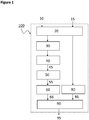
- Figure 1 shows a first general block diagram of an example system 100 for calculating cardiac pulse transit/arrival time information between a primary cardiac pulse signal 15 and an electronic audio signal 10.
- the system comprises a signal receiving module 20, an audio processing module 30, a denoising module 40, a signal transformation module 50, a beat detection module 60, a primary cardiac pulse beat detection module 80, and a cardiac pulse transit/arrival time module 90.
- calculating pulse transit time information may be understood as calculating PTT and/or PAT information.
- the electronic audio signal 10 comprises information representative of a subject's voice signal in the time domain.
- the subject's voice signal comprises a vowel audio sound of a certain duration and a fundamental frequency ( F0 in Figure 4 ).
- the electronic audio signal 10 may comprise a vowel audio sound that the subject has to sustain for a certain period or a vowel sound that is extracted from the subject's speech (e.g. by recognizing a vowel sound that has a certain duration or by stitching a plurality of vowel sounds).
- the electronic audio signal 10 may comprise a vowel audio sound having a certain minimum duration so as to comprise a detectable fundamental frequency characteristic of that subject.
- the electronic audio signal 10 may be a real-time signal or may be a non-real time recorded signal that can be also postprocessed with a latency or in non-real time.
- the electronic primary cardiac pulse signal 15 comprises information representative of the subject's cardiac pulse in the time domain.
- the electronic cardiac pulse signal may be an electrocardiogram signal (ECG), an impedance cardiogram signal (ICG), a cardiac ultrasound signal recorded by an echogram or sonogram, a heart sound signal from a stethoscope sensor, a photoplethysmogram signal (PPG), an impedance plethysmogram signal (IPG), a speckle plethysmogram signal (SPG), or a pressure signal from a piezo sensor.
- the electronic primary cardiac pulse signal 15 may be a real-time signal or may be a non-real time recorded signal that can be also postprocessed with a latency or in non-real time. According to example embodiments, the electronic cardiac pulse signal is used as a source timing reference for the computation of transit/arrival times with respect to the electronic audio signal 10.
- the signal receiving module 20 is configured for receiving the electronic audio signal 10, e.g. from an audio sensor or transducer, such as for example a microphone, and the electronic primary cardiac pulse signal 15, e.g. from ECG electrodes connected to the subject's body.
- the signal receiving module 20 may comprise wired or wireless transmission/receiving means to receive such electronic signals.
- the signal receiving module 20 may comprise a storage or memory in which such electronic audio signals are temporarily or permanently stored.
- the signal receiving module 20 may just comprise means for reading the electronic signals from a memory or storage unit.
- the electronic audio signal is an analogue or digital audio signal in the kHz range.
- the signal receiving module 20 may comprise analogue to digital conversion and audio signal conditioning means. According to some embodiments, the signal receiving module 20 receives the electronic audio signal and the primary cardiac pulse signal in a synchronized manner, that is, wherein the electronic audio signal and the primary cardiac pulse signal are synchronized in the time domain. According to some example embodiments, the synchronization between the primary cardiac pulse signal and the audio signal is performed in hardware, meaning that the digitizing circuits for both signals share the same clock. In some example embodiments, when each of the digitizing circuits receives a sample (or a reduced group of them) the digitizing circuit also collects the timestamp, which has a common clock source for both signals. According to some example embodiments, even if using an independent clock for each of the signals, a software-based synchronization may also be performed.
- the audio processing module 30 is configured for generating a power spectral profile of a section of the electronic audio signal 10 and detecting the fundamental frequency ( F0 in Figure 4 ) of the generated power spectral profile.
- a small portion of the voice is extracted from the electronic audio signal 10, and from it a power spectral profile is computed (see Figure 4 ).
- from the power spectral profile, around the first peak detected is considered the fundamental frequency of the voice signal.
- the audio processing module 30 may be also configured for calculating or detecting subsequent harmonics of the fundamental frequency, located at around 2, 3, 4, ...N times the fundamental frequency.
- the denoising module 40 is configured for filtering the received audio signal within a band around at least the detected fundamental frequency and thereby generating a denoised audio signal 45.
- the denoising unit performs a bandpass filtering of the electronic audio signal 10 around the fundamental frequency F0 to reduce the sources of noise and avoid aliasing.
- the bandpass filtering can be done up to about +/- 10Hz around the fundamental frequency.
- the denoising module may be further configured for filtering the received electronic audio signal 10 also within bands around one or more harmonics or multiples of the detected fundamental frequency ( 2F0,3F0, ...NF0 in Figure 4 ) and for generating one or more denoised audio signals.
- the bandpass filtering can be also done up to about +/- 10Hz around the harmonics.
- the denoising module 40 may generate a first denoised audio signal for the fundamental frequency and a second denoised audio signal for one of the corresponding harmonics.
- the denoising module 40 may generate also denoised audio signals for each of the harmonics (e.g. bandpass filtering the electronic audio signal 10 around the harmonic NF0 ).
- the denoising module may generate one denoised audio signal by bandpass filtering of the electronic audio signal 10 around the fundamental frequency F0 and around one or more harmonics.
- the signal transformation module 50 is configured for generating a time domain intermediate signal 55 that captures frequency, amplitude and/or phase of the generated denoised audio signal 45.
- the signal transformation module may be configured for calculating the Hilbert transform of the denoised audio signal, the complex autocorrelation with M samples delay, and the instantaneous frequency, thereby generating a time domain intermediate signal capturing the frequency of the denoised audio signal.
- the signal transformation module may be configured for generating an in-phase and quadrature signal of the denoised audio signal, with a carrier having a frequency that is the fundamental frequency, and calculating the L2 norm of the in-phase and quadrature signals over time, thereby generating a time domain intermediate signal capturing the amplitude of the denoised audio signal.
- the signal transformation module may be configured for generating an in-phase and quadrature signal of the denoised audio signal, with a carrier having a frequency that is the fundamental frequency; and calculating the phase of the in-phase and quadrature signals, thereby generating a time domain intermediate signal capturing the phase of the denoised audio signal.
- the signal transformation module is configured for combining calculated results from each of the denoised audio signals.
- the beat detection module 60 is configured for detecting at least one intermediate signal fiducial point 66 within a human cardiac band in the intermediate signal 55.
- said human cardiac band is around 40 to 200 bpm or 0.6Hz to 3.5Hz.
- the beat detection module is configured for detecting heartbeat information within a human cardiac band in the intermediate signal, on the time domain.
- said beat detection module is configured for extracting at least a time fiducial point from the intermediate signal 55, which is representative of the subject's heartbeat.
- such detected fiducial points may be based on peak detection in the signal or its derivatives, zero crossings or other time domain fiducial points.
- said beat detection module 60 is configured for detecting a plurality of intermediate signal fiducial points, representative of beat by beat information of the subject's heartbeats.
- the beat detection module may be configured for performing a bandpass filtering of the intermediate signal around a human cardiac band.
- the primary cardiac pulse beat detection module 80 is configured for detecting at least one primary cardiac pulse fiducial point 86 within a human cardiac band, in the primary cardiac pulse signal 15.
- said human cardiac band is around 40 to 200 bpm or 0.6Hz to 3.5Hz.
- the primary cardiac pulse beat detection module is configured for detecting cardiac pulse information, within a human cardiac band, on the time domain.
- said primary cardiac pulse beat detection module is configured for extracting at least a time fiducial point from the cardiac pulse signal 15, which is representative of the subject's heartbeat.
- the cardiac pulse signal 15 is an ECG signal
- the primary cardiac pulse beat detection module may be configured for detecting R peak fiducial points.
- the primary cardiac pulse beat detection module may be configured for detecting B fiducial points.
- the beat detection module may be configured for performing a bandpass filtering of the intermediate signal around a human cardiac band.
- the cardiac pulse transit/arrival time module 90 is configured for calculating pulse transit time information 95 between at least one of the detected primary cardiac signal fiducial points 86 and at least one of the detected intermediate signal fiducial points 66. According to example embodiments, the cardiac pulse transit/arrival time module 90 is configured for calculating a time difference between at least one detected primary cardiac signal fiducial point and at least one detected intermediate signal fiducial point corresponding to the same subject's heartbeat. According to example embodiments, the cardiac pulse transit/arrival time module 90 is configured for receiving timing information about a plurality of detected fiducial points from the primary cardiac pulse signal and the intermediate signal and for calculating timing differences (PTT/PAT) for a plurality of the subject's heart beats, e.g. one PTT/PAT value per beat. According to example embodiments, the cardiac pulse transit/arrival time module 90 may also calculate statistically filtered (e.g. mean or median) PTT/PAT values.
- PTT/PAT timing differences
- the system 100 for calculating cardiac pulse transit time information is configured for removing transition sections (e.g. start and end of audio signal recordings) when calculating transit/arrival times.
- the system 100 for calculating cardiac pulse transit time information is configured for accounting for and compensating any delays, either systematic (setup dependent) or introduced by the system while processing the electronic audio signal 10 and the primary cardiac pulse signal 15.
- systematic delays may include hardware, software and/or measurement principle delays.
- measurement principle additive time offset can come from the time the voice needs to travel the distance between the vocal chords and the microphone collecting audio (in which voice travels at the speed of sound).
- System-introduced delays include processing delays for instance when signals are filtered.
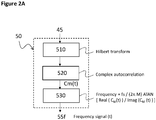
- Figure 2A shows a block diagram of a first example signal transformation module 50 configured for generating a time domain intermediate signal 55f that captures the frequency of the generated denoised audio signal 45.
- the signal transformation module is configured for calculating the Hilbert transform of the received denoised audio signal, calculating the complex autocorrelation of the Hilbert transform with M samples delay C M (t), calculating the instantaneous frequency and low pass filtering the instantaneous frequency signal to avoid aliasing.
- the signal transformation module 50 may further be configured for down sampling the instantaneous frequency signal, which may be advantageous for real-time operation processing.
- the down-sampling is done to a human cardiac-like sampling frequency, e.g. 256 Hz.
- Figure 2B shows a block diagram of a second example signal transformation module 50 configured for generating a time domain intermediate signal 55a that captures the amplitude of the generated denoised audio signal 45.
- the signal transformation module is configured for generating an in-phase I(t) and quadrature Q(t) signal of the denoised audio signal, with a carrier having a frequency that is the fundamental frequency and calculating the L2 norm of the in-phase and quadrature signals.
- the signal transformation module is configured for: generating a sine wave having the fundamental frequency, and multiplying the denoised audio signal by said sine wave, thereby generating the in-phase signal I(t); generating a cosine wave having the fundamental frequency, and multiplying the denoised audio signal by said cosine wave, thereby generating the quadrature signal Q(t); and calculating the sample-by-sample square root of the sum of the squares of the in-phase and quadrature signals over time.
- the signal transformation module 50 may further be configured for low pass filtering and/or down sampling the in-phase I(t) and/or the quadrature signal Q(t), which may be advantageous for avoiding aliasing or for real-time operation processing.
- the down-sampling is done to a human cardiac-like sampling frequency, e.g. 256 Hz.
- Figure 2C shows a block diagram of a third example signal transformation module 50 configured for generating a time domain intermediate signal 55p that captures the amplitude of the generated denoised audio signal 45.
- the signal transformation module is configured for generating an in-phase I(t) and quadrature Q(t) signal of the denoised audio signal, with a carrier having a frequency that is the fundamental frequency and calculating the phase of the in-phase and quadrature signals.
- the signal transformation module is configured for: generating a sine wave having the fundamental frequency, and multiplying the denoised audio signal by said sine wave, thereby generating the in-phase signal I(t) ; generating a cosine wave having the fundamental frequency, and multiplying the denoised audio signal by said cosine wave, thereby generating the quadrature signal Q(t); and calculating the arctangent of the in-phase signal divided by the quadrature signal.
- the signal transformation module may be configured for compensating the phase by 2 pi shifts in order to enforce signal continuity.
- the signal transformation module 50 may further be configured for low pass filtering and/or down sampling the in-phase I(t) and/or the quadrature signal Q(t), which may be advantageous for avoiding aliasing or for real-time operation processing.
- the down-sampling is done to a human cardiac-like sampling frequency, e.g. 256 Hz.
- Figure 3 shows a block diagram of a fourth example signal transformation module 50 configured for generating a time domain intermediate signal 55a that captures the amplitude of a plurality of generated denoised audio signal 45.
- the signal transformation module is configured for: generating an in-phase I(t) and quadrature Q(t) signal for each of a plurality of denoised audio signals (e.g. one corresponding to the fundamental frequency and at least another one corresponding to one harmonic), with a carrier having a frequency that is the fundamental frequency; calculating the modulus of the in-phase and quadrature signals; and combining calculated amplitude results from each of the denoised audio signals.
- a plurality of denoised audio signals e.g. one corresponding to the fundamental frequency and at least another one corresponding to one harmonic
- the signal transformation module is configured for: generating an in-phase I(t) and quadrature Q(t) signal for each of a plurality of denoised audio signals (e.g. one corresponding to the fundamental frequency and at least another one corresponding to one harmonic), with a carrier having a frequency that is the fundamental frequency; combining generated in-phase I(t) and quadrature Q(t) signal values for each of the denoised audio signals; and calculating the modulus of the combined in-phase and quadrature signals.
- a plurality of denoised audio signals e.g. one corresponding to the fundamental frequency and at least another one corresponding to one harmonic
- Figure 3 only shows an example for a signal transformation module 50 configured for generating a time domain intermediate signal 55a that captures the amplitude of a plurality of generated denoised audio signals 45, similar combinations can be done for a signal transformation module 50 configured for generating a time domain intermediate signal 55p that captures the phase of a plurality of generated denoised audio signals 45.
- the signal transformation module is configured for: combining the received denoised audio signals; calculating the Hilbert transform of the combined audio signals; calculating the complex autocorrelation with M samples delay C M (t) ; calculating the instantaneous frequency, and low pass filtering the instantaneous frequency signal.
- the signal transformation module is configured for: calculating the Hilbert transform of each of the received denoised audio signals; calculating the complex autocorrelation with M samples delay C M (t) of each of the received denoised audio signals; calculating the instantaneous frequency for each of the C M (t) ; combining the instantaneous frequencies and low pass filtering the instantaneous frequency signal.
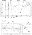
- Figure 4 illustrates a graph of an example electronic audio signal 10 in frequency domain, comprising a vowel audio sound having a fundamental frequency F0, and a plurality of harmonics 2F0, 3F0, 4F0, ...NF0.
- Further example demodulation signals generated by the signal transformation module 50 are also shown together with the synthetically generated cosine signal with frequencies F0 and a plurality of harmonics 2F0, 3F0, 4F0 used in the demodulation process.
- the frequency content of the input signal at the DC level is low to non-existing, whereas the demodulated signal levels in the DC area reflects the contents of the bands around the harmonics in the input signal. Such bandwidth contains the cardiac information to be decoded.
- Figure 5 illustrates a graph, in time domain (left) and frequency domain (right), of an example intermediate signal 55p with phase information, generated by the signal transformation module 50.
- the intermediate signal 55p is compared with a primary cardiac pulse signal pz from a piezo-based sensor in the thumb measuring volumetric displacement.
- the time domain graph (left) shows how the pulsatility of the signal 55p is similar to that of the primary cardiac pulse piezo signal pz .
- the frequency domain signal (right) reflects that the fundamental frequency of both the signals 55p (highest frequency peak) and reference pz (first peak) are in the exact same frequency location.
- the signal transformation beat detection module 60 may provide information based on any of the time domain intermediate signals 55 generated by the signal transformation module 50. According to example embodiments, the signal transformation beat detection module 60 may provide multiple information based on a plurality of time domain intermediate signals 55f, 55a, 55p generated by the signal transformation module 50. According to example embodiments, the signal transformation beat detection module 60 may provide information based on a weighted or quality-related values derived from a plurality of time domain intermediate signals 55f, 55a, 55p. In consequence, according to example embodiments, the cardiac pulse transit/arrival time module 90 may therefore provide pulse transit/arrival time information based on any of the time domain intermediate signals 55 generated by the signal transformation module 50.
- the cardiac pulse transit/arrival time module 90 may provide multiple pulse transit/arrival time information based on a plurality of time domain intermediate signals 55f, 55a, 55p generated by the signal transformation module 50. According to example embodiments, the cardiac pulse transit time module 90 may provide pulse transit/arrival time information based on a weighted or quality-related values derived from a plurality of time domain intermediate signals 55f, 55a, 55p.
- the system 100 for calculating cardiac pulse transit/arrival time information may be implemented according to hardware and/or software state of the art techniques, comprising for example a microprocessor, microcontroller or digital signal processor that can understand and execute software program instructions. Some programmable hardware logic, ASIC and/or memory means may be specifically designed also for executing the method or parts of it according to example embodiments of the invention.
- the system may be implemented in an electronic device.
- the electronic device may be a wearable or a tethered device.
- the system may work in real time, almost real time (with a latency) or in post-processing.
- Figure 6 shows an example flow diagram 200 for calculating cardiac pulse transit/arrival time information of a subject, between a primary cardiac pulse signal 215 and an electronic audio signal 210.
- the method may be implemented in an electronic system or device, such as the ones described herein, or in a computer or processing unit.
- the electronic audio signal comprises information representative of a human voice signal in the time domain, said human voice signal comprises a vowel audio sound of a certain duration and a fundamental frequency.
- the method comprises: 220, receiving the electronic audio signal and the primary cardiac pulse signal, wherein the electronic audio signal and the primary cardiac pulse signal are synchronized time domain signals; 230, generating a power spectral profile of a section of the electronic audio signal, and detecting the fundamental frequency of the generated power spectral profile; 240, filtering the received audio signal within a band around at least the detected fundamental frequency and thereby generating a denoised audio signal 245; 250, generating a time domain intermediate signal 255 that captures frequency, amplitude and/or phase of the denoised audio signal; 260, detecting at least one intermediate signal fiducial point 266 within a human cardiac band in the intermediate signal 255; 280, detecting at least one primary cardiac pulse fiducial point 286 within a human cardiac band in the primary cardiac pulse signal 215; and 290, calculating pulse transit/arrival time information 295 between the at least one detected primary cardiac signal fiducial point 286 and the at least one detected intermediate signal fiducial point 266.
- said human cardiac band is around 40 to 200 bpm or 0.6Hz to 3.5Hz.
- the step 260 of detecting at least one intermediate signal fiducial point may comprise performing a bandpass filtering of the intermediate signal around a human cardiac band.
- the step 260 of detecting at least one intermediate signal fiducial point 266 comprises detecting fiducial points within a human cardiac band in the intermediate signal, on the time domain.
- the step 260 of detecting at least one intermediate signal fiducial point 266 comprises extracting at least a time fiducial point from the intermediate signal 255, which is representative of the subject's heartbeat.
- such detection of fiducial points may be based on peak detection in the signal or its derivatives, zero crossings or other time domain fiducial points.
- the step 260 of detecting at least one intermediate signal fiducial point comprises detecting a plurality of intermediate signal fiducial points, representative of beat by beat information of the subject's heartbeats.
- the step 280 of detecting at least one primary cardiac pulse fiducial point may comprise performing a bandpass filtering of the primary cardiac pulse signal around a human cardiac band.
- the step 280 of detecting at least one primary cardiac pulse fiducial point comprises detecting fiducial points within a human cardiac band in the primary cardiac pulse signal, on the time domain.
- the step 280 of detecting at least one primary cardiac pulse fiducial point comprises extracting at least a time fiducial point from the cardiac pulse signal 215, which is representative of the subject's heartbeat.
- the step 280 of detecting at least one primary cardiac pulse fiducial point comprises detecting one or more R peak fiducial points.
- the step 280 of detecting at least one primary cardiac pulse fiducial point comprises detecting one or more B fiducial points.
- the step 290 of calculating pulse transit/arrival time information 295 comprises calculating a time difference between at least one detected primary cardiac signal fiducial point and at least one detected intermediate signal fiducial point corresponding to the same subject's heartbeat.
- the step 290 of calculating pulse transit/arrival time information 295 comprises receiving timing information about a plurality of detected fiducial points from the primary cardiac pulse reference signal and the intermediate signal and calculating timing differences (PTT/PAT) for a plurality of the subject's heartbeats, e.g. one PTT/PAT value per beat.
- the step 290 of calculating pulse transit time information 295 comprises calculating statistically filtered (e.g. mean or median) PTT/PAT values.
- the method 200 for calculating cardiac pulse transit/arrival time information comprises removing transition sections (e.g. start and end portions of the electronic audio signal) when calculating transit/arrival times.
- the method 200 for calculating cardiac pulse transit/arrival time information comprises accounting for and compensating any delays introduced by the electronic system while processing the electronic audio signal 10 and a primary cardiac pulse signal 15.
- Figure 7A shows a first example flow diagram for the step 250 of generating a time domain intermediate signal 255f that captures frequency information.
- the method comprises: 2510, calculating a Hilbert transform of the denoised audio signal 245; 2520, calculating a complex autocorrelation with M samples delay of the Hilbert transform; and 2530, calculating the instantaneous frequency.
- Figure 7B shows a second example flow diagram for the step 250 of generating a time domain intermediate signal 255a that captures amplitude information.
- the method comprises: 2550, generating an in-phase and a quadrature signal of the denoised audio signal 245, with a carrier having a frequency that is the fundamental frequency; and 2560, calculating the L2 norm of the in-phase and quadrature signals.
- Figure 7C shows a third example flow diagram for the step 250 of generating a time domain intermediate signal 255p that captures phase information.
- the method comprises: 2550, generating an in-phase and a quadrature signal of the denoised audio signal, with a carrier having a frequency that is the fundamental frequency; and 2570, calculating the phase of the in-phase and quadrature signals.
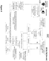
- Figure 8 shows a second example flow diagram 200' for calculating cardiac pulse transit time information of a subject, from an electronic audio signal 210 and a primary cardiac pulse signal 215.
- the electronic audio signal 210 may be generated by an audio acquisition module comprising a sensor (microphone), digitizer and signal conditioning of the audio signal. The output of the acquisition is a digital audio signal at a voice like sample rate (in the kHz range).
- the primary cardiac pulse signal 215 may be generated by a corresponding acquisition module comprising an analogue front end and digitizing circuitry, resulting in a digital signal in the time domain. The primary cardiac pulse signal is going to be used as time reference for arrival time computation.
- the acquisition of the electronic audio signal 210 and the primary cardiac pulse signal 215 is performed under synchronization of both signal acquisition modules.
- the synchronization between the primary cardiac pulse signal and the electronic audio signal is performed in hardware, meaning that the digitizer circuits share the same clock.
- the digitizer when each of the two digitizers receives a sample (or a reduced group of them) the digitizer also collects the timestamp, which has a common clock source in both of them.
- independent clocks may be used, and synchronization of the signals may be performed using software or other hardware means.
- the electronic audio signal 210 and the primary cardiac pulse signal 215 may be just stored on a memory or storage unit and read.
- the electronic audio signal 210 and the primary cardiac pulse signal 215 may be just received by wired or wireless transmission means.
- the method comprises extracting a power spectral profile of a small section of the electronic audio signal.
- a small portion of the voice is extracted and from it a power spectral profile is computed.
- the method comprises detecting the fundamental frequency of the voice signal from the power spectral profile.
- the first peak of the power spectral profile is the fundamental frequency. Based on the detection of the fundamental frequency the subsequent harmonics should be at 2, 3, 4, etc times the fundamental frequency.
- the method can be performed up to N harmonics.
- the method comprises:
- the method further comprises: optionally, performing a bandpass of the frequency, amplitude and phase signals: the extracted frequency, amplitude and phase modulations in the voice are filtered in the bandwidth of interest of Cardiac systems. This is roughly in the bandwidth corresponding to heart rates between 40 and 200 beats per minute.
- bandpass filtering the filtering delay of the pulse needs to be controlled and accounted for, as it needs to be compensated. This delay may also be accounted for by design or compensated during a configuration phase.
- the method further comprises: extracting frequency, amplitude and phase relevant points from the signal related to heart beat information.
- one or more time fiducial points are extracted from the amplitude and phase, which is characteristic of every beat in the signal.
- Such fiducial point can be based on peak detection in the signal or its derivatives, zero crossings or other time domain fiducial points. It should be characteristic for each of the beats.
- the method may further comprise filtering the primary cardiac pulse signal in the bandwidth of interest of cardiac systems. This is roughly in the bandwidth corresponding to heart rates between 40 and 180 beats per minute.
- the method further comprises extracting time fiducial points from the primary cardiac pulse, which is characteristic of every beat in the signal. For instance, in an ECG signal this would be the R peak detector, or in an ICG signal the B point. Multiple options of fiducial points are possible for the multiple signals used as time reference. The fiducial points found and its timing, referred to the original clock are reported.
- the method further comprises correcting for any delay, e.g. filtering, up/down sampling, introduced in any stage by the system in the primary cardiac pulse and/or electronic audio signal paths.
- any delay e.g. filtering, up/down sampling, introduced in any stage by the system in the primary cardiac pulse and/or electronic audio signal paths.
- the method further comprises computing the differences between the timing of the fiducial points of the cardiac reference pulse signal and the timing of the fiducial points of the frequency, amplitude and phase signals. These differences may be calculated for every beat (one value per beat) and can be potentially statistically filtered (mean, median, etc).
- the method further comprises removing the transition sections of the voice (startup and end of recording) due to frequency variations.
- the method calculates pulse arrival time from cardiac pulse to frequency modulated voice timing (per beat); pulse arrival time from cardiac pulse to amplitude modulated voice timing (per beat); and/or pulse arrival time from cardiac pulse to phase modulated voice timing (per beat).
- Figure 9 shows a third example flow diagram 200" for calculating cardiac pulse transit time information of a subject, from an electronic audio signal 210 and a primary cardiac pulse signal 215.
- the denoised audio signal can be also processed at once (not per harmonic as in Figure 8 ).
- the step of filtering the received audio signal within a band around at least the detected fundamental frequency and thereby generating a denoised audio signal 245, comprises performing multiple band pass filters preserving the bandwidth around all the selected N harmonics (e.g. typically +/- 10Hz around each of the harmonics). This may be a composite filtering resulting from linearly combining filters for all the harmonics.
Landscapes
- Health & Medical Sciences (AREA)
- Life Sciences & Earth Sciences (AREA)
- Engineering & Computer Science (AREA)
- Public Health (AREA)
- Physics & Mathematics (AREA)
- General Health & Medical Sciences (AREA)
- Biomedical Technology (AREA)
- Veterinary Medicine (AREA)
- Heart & Thoracic Surgery (AREA)
- Medical Informatics (AREA)
- Molecular Biology (AREA)
- Surgery (AREA)
- Animal Behavior & Ethology (AREA)
- Biophysics (AREA)
- Pathology (AREA)
- Physiology (AREA)
- Cardiology (AREA)
- Signal Processing (AREA)
- Computer Vision & Pattern Recognition (AREA)
- Psychiatry (AREA)
- Artificial Intelligence (AREA)
- Vascular Medicine (AREA)
- Audiology, Speech & Language Pathology (AREA)
- Ophthalmology & Optometry (AREA)
- Pulmonology (AREA)
- Epidemiology (AREA)
- Computational Linguistics (AREA)
- Human Computer Interaction (AREA)
- Acoustics & Sound (AREA)
- Multimedia (AREA)
- Measuring Pulse, Heart Rate, Blood Pressure Or Blood Flow (AREA)
Abstract
A device for calculating a subject's cardiac pulse transit time or pulse arrival time information is configured for receiving an electronic audio signal with information representative of a human voice signal and a primary cardiac pulse signal (15), generating a power spectral profile of a section of the electronic audio signal (10), and detecting a fundamental frequency (F0) of the generated power spectral profile; generating a denoised audio signal (45); generating a time-domain intermediate signal (55) that captures frequency, amplitude and/or phase of the denoised audio signal (45); detecting at least one intermediate signal fiducial point (66), within a human cardiac band, in the intermediate signal (55); detecting at least one primary cardiac pulse fiducial point (86), within a human cardiac band, in the primary cardiac pulse signal (15); and calculating pulse transit time or pulse arrival time information (95) between the at least one detected primary cardiac signal fiducial point (86) and the at least one detected intermediate signal fiducial point (66).
Description
- The present description relates generally to electronic systems for calculating cardiac pulse transit time (PTT) or pulse arrival time (PAT) information and more specifically to an electronic system for calculating cardiac pulse transit/arrival time using a primary cardiac pulse signal and an electronic audio signal input.
- Continuous, non-invasive and cuff-less estimation of arterial blood pressure (BP) gained emerging interest for health care applications. Instead of commonly used cuff-based measurements, changes in the Pulse Wave Velocity (PWV), i.e., the speed of a pressure pulse propagating along the arterial wall, can be an alternative approach for a continuous, non-invasive and indirect BP measurement. As a surrogate of PWV, an indirect estimation of BP can be also obtained with the use of Pulse Transit Time (PTT) or Pulse Arrival Time (PAT). PWV can be computed as a ratio between the distance the pulse travels and the transit/arrival times (PTT or PAT). Pulse transit time methods can be also used as proxy measurements for arterial stiffness. Therefore, there is an increasing interest for PTT/PAT calculation techniques that can be used as a cardiovascular variable or as an indicator for blood pressure (both systemic and pulmonary) and arterial stiffness. An example technique is disclosed in " Pulse Transit Time Measurement using Seismocardiogram and In-Ear Acoustic Sensor", by C. Yang et al, 2016 IEEE Biomedical Circuits and Systems Conference (BioCAS), pp. 188-191, 2016.
- There is a motivation to improve current state of the art electronic systems and methods for non-invasive calculation of cardiac pulse transit or arrival times.
- A new and improved system and method for non-invasively calculating cardiac pulse transit or arrival time information is proposed herein, which allow calculating a subject's cardiac pulse transit or arrival time using a primary cardiac pulse signal recorded from said subject (used as time reference for the pulse) and fiducial points detected in an electronic audio signal generated by the subject. According to example embodiments, the electronic system is advantageously able to calculate a subject's cardiac pulse transit or arrival time using calculations in the time-domain. According to an example embodiment, the electronic system advantageously makes use of synchronized voice and cardiac signals for calculating pulse arrival time information. According to an example embodiment, the electronic system is advantageously able to process cardiac signals preserving the phases of the signal (or relative phases). According to an example embodiment, the electronic system can advantageously process the audio and cardiac signal and provide PTT/PAT information in real-time, while the subject is generating the audio signal. According to an example embodiment, the electronic system can process the audio and cardiac signal and provide PTT/PAT information beat by beat. According to example embodiments, additional statistics can be computed based on the beat by beat information (e.g. average N beats to provide a more robust output). According to an example embodiment, the electronic system advantageously provides for a synchronous demodulation of the audio signal based on the fundamental frequency of a vowel audio sound. According to an example embodiment, the system can automatically adapt to different subjects' voices, thus avoiding the need for training configuration phases. According to an example embodiment, the method herein described advantageously exposes hard to measure cardiovascular parameters. According to an example embodiment, the solution can be implemented in a wearable sensor or integrated in a distributed electronic device network. The method of the invention can also be implemented as a software solution on, for example, a smartphone or an offline system based on recorded (but synchronized) signals.
- According to an example embodiment, there is provided an electronic system for calculating a subject's cardiac pulse transit time or pulse arrival time information using a primary cardiac pulse signal and an electronic audio signal, wherein the electronic audio signal comprises information representative of a human voice signal in the time domain, said human voice signal comprising a vowel audio sound of a certain duration and a fundamental frequency; and wherein the electronic system comprises: a signal receiving module configured for receiving the electronic audio signal and the primary cardiac pulse signal, wherein the electronic audio signal and the primary cardiac pulse signal are synchronized time domain signals; an audio processing module configured for generating a power spectral profile of a section of the electronic audio signal, and for detecting the fundamental frequency of the generated power spectral profile; a denoising module configured for filtering the received audio signal within a band around at least the detected fundamental frequency and thereby generating a denoised audio signal; a signal transformation module configured for generating a time domain intermediate signal that captures frequency, amplitude and/or phase of the denoised audio signal; a beat detection module configured for detecting at least one intermediate signal fiducial point, within a human cardiac band, in the intermediate signal; a primary cardiac pulse beat detection module configured for detecting at least one primary cardiac pulse fiducial point, within a human cardiac band, in the primary cardiac pulse signal; a cardiac pulse transit/arrival time module configured for calculating pulse transit time or pulse arrival time information between the at least one detected primary cardiac signal fiducial point and the at least one detected intermediate signal fiducial point.
- According to an example embodiment, the signal source is the heart, and the timing is from the first signal to be generated in time (the primary cardiac pulse signal) to the electronic audio signal (which receives the pulse later). According to an example embodiment, if the primary cardiac pulse signal is an ECG signal, the outcome is pulse arrival time (PAT). According to example embodiments, if the primary pulse is a PPG or ICG signal the outcome would be pulse transit time (PTT).
- According to an example embodiment, the signal transformation module is configured for receiving the denoised audio signal and calculating the Hilbert transform; the complex autocorrelation with M samples delay; and the instantaneous frequency, thereby generating a time domain intermediate signal capturing the frequency of the denoised audio signal.
- According to an example embodiment, the signal transformation module is configured for generating an in-phase and quadrature signal of the denoised audio signal, with a carrier having a frequency that is the fundamental frequency; and calculating the L2 norm of the in-phase and quadrature signals, thereby generating a time domain intermediate signal capturing the amplitude of the denoised audio signal.
- According to an example embodiment, the signal transformation module is configured for generating an in-phase and quadrature signal of the denoised audio signal, with a carrier having a frequency that is the fundamental frequency; and calculating the phase of the in-phase and quadrature signals, thereby generating a time domain intermediate signal capturing the phase of the denoised audio signal.
- According to an example embodiment, the denoising module is further configured for filtering the received audio signal also within bands around one or more multiples of the detected fundamental frequency and for generating one or more denoised audio signals.
- According to an example embodiment, the denoising module is configured for generating a plurality of denoised audio signals and the signal transformation module is configured for combining calculation results from each of the denoised audio signals.
- The invention also relates to an electronic device comprising the electronic system for calculating cardiac pulse transit or arrival time information of a subject according to embodiments herein described.
- The invention also relates to a method for, in an electronic system or device, calculating cardiac pulse transit or arrival time information of a subject, between a primary cardiac pulse signal and an electronic audio signal, wherein the electronic audio signal comprises information representative of a human voice signal in the time domain, said human voice signal comprising a vowel audio sound of a certain duration and a fundamental frequency; and the method comprising: receiving the electronic audio signal and the primary cardiac pulse signal, wherein the electronic audio signal and the primary cardiac pulse signal are synchronized time domain signals; generating a power spectral profile of a section of the electronic audio signal, and detecting the fundamental frequency of the generated power spectral profile; filtering the received audio signal within a band around at least the detected fundamental frequency and thereby generating a denoised audio signal; generating a time domain intermediate signal that captures frequency, amplitude and/or phase of the denoised audio signal; and detecting at least one intermediate signal fiducial point within a human cardiac band in the intermediate signal; detecting at least one primary cardiac pulse fiducial point within a human cardiac band in the primary cardiac pulse signal; calculating pulse transit or arrival time information between the at least one detected primary cardiac signal fiducial point and the at least one detected intermediate signal fiducial point.
- According to an example embodiment, the step of generating a time domain intermediate signal that captures frequency of the denoised audio signal, comprises: calculating a Hilbert transform; calculating a complex autocorrelation with M samples delay; and calculating the instantaneous frequency.
- According to an example embodiment, the step of generating a time domain intermediate signal that captures amplitude of the denoised audio signal, comprises: generating an in-phase and a quadrature signal of the denoised audio signal, with a carrier having a frequency that is the fundamental frequency; and calculating the L2 norm of the in-phase and quadrature signals.
- According to an example embodiment, the step of generating a time domain intermediate signal that captures the phase of the denoised audio signal (545), comprises: generating an in-phase and a quadrature signal of the denoised audio signal, with a carrier having a frequency that is the fundamental frequency; and calculating the phase of the in-phase and quadrature signals.
- The invention also relates to a computer program product comprising computer program code means adapted for calculating cardiac pulse transit or arrival time information of a subject, according to the methods herein described when said program is run on a computer, and to a computer readable storage medium comprising such computer program.
- The above and other aspects of the system and method according to the present description will be shown and explained with reference to the non-restrictive example embodiments described hereinafter.
-
Figure 1 shows a first general block diagram of an example system for calculating cardiac pulse transit or arrival time information. -
Figure 2A shows a block diagram of a first example signal transformation module. -
Figure 2B shows a block diagram of a second example signal transformation module. -
Figure 2C shows a block diagram of a third example signal transformation module. -
Figure 3 shows a block diagram of a fourth example signal transformation module. -
Figure 4 illustrates a graph of an example electronic audio signal comprising a vowel audio sound having a fundamental frequency, in relation to other signals generated by the electronic system based on that fundamental frequency. -
Figure 5 illustrates a graph of an example time domain intermediate signal with phase information, generated by the signal transformation module, and the comparison of the intermediate signal and a primary cardiac pulse signal in the frequency domain, showing the same location of the first harmonic. -
Figure 6 shows a first example flow diagram for calculating cardiac pulse transit or arrival time information. -
Figure 7A shows a first example flow diagram for generating a time domain intermediate signal that captures frequency information. -
Figure 7B shows a second example flow diagram for generating a time domain intermediate signal that captures amplitude information. -
Figure 7C shows a third example flow diagram for generating a time domain intermediate signal that captures phase information. -
Figure 8 shows a second example flow diagram for calculating cardiac pulse transit or arrival time information. -
Figure 9 shows a third example flow diagram for calculating cardiac pulse transit or arrival time information. - In the following, in the description of example embodiments, various features may be grouped together in a single embodiment, figure, or description thereof for the purpose of streamlining the disclosure and aiding in the understanding of one or more of the various inventive aspects. This is however not to be interpreted as the invention requiring more features than the ones expressly recited in the main claim. Furthermore, combinations of features of different embodiments are meant to be within the scope of the invention, as would be clearly understood by those skilled in the art. Additionally, in other instances, well-known methods, structures and techniques have not been shown in detail in order not to obscure the conciseness of the description.
-
Figure 1 shows a first general block diagram of anexample system 100 for calculating cardiac pulse transit/arrival time information between a primarycardiac pulse signal 15 and anelectronic audio signal 10. The system comprises asignal receiving module 20, anaudio processing module 30, adenoising module 40, asignal transformation module 50, abeat detection module 60, a primary cardiac pulsebeat detection module 80, and a cardiac pulse transit/arrival time module 90. In the following description, according to some examples, calculating pulse transit time information may be understood as calculating PTT and/or PAT information. - The
electronic audio signal 10 comprises information representative of a subject's voice signal in the time domain. The subject's voice signal comprises a vowel audio sound of a certain duration and a fundamental frequency (F0 inFigure 4 ). In some embodiments, theelectronic audio signal 10 may comprise a vowel audio sound that the subject has to sustain for a certain period or a vowel sound that is extracted from the subject's speech (e.g. by recognizing a vowel sound that has a certain duration or by stitching a plurality of vowel sounds). According to example embodiments, theelectronic audio signal 10 may comprise a vowel audio sound having a certain minimum duration so as to comprise a detectable fundamental frequency characteristic of that subject. Theelectronic audio signal 10 may be a real-time signal or may be a non-real time recorded signal that can be also postprocessed with a latency or in non-real time. - The electronic primary
cardiac pulse signal 15 comprises information representative of the subject's cardiac pulse in the time domain. According to example embodiments, the electronic cardiac pulse signal may be an electrocardiogram signal (ECG), an impedance cardiogram signal (ICG), a cardiac ultrasound signal recorded by an echogram or sonogram, a heart sound signal from a stethoscope sensor, a photoplethysmogram signal (PPG), an impedance plethysmogram signal (IPG), a speckle plethysmogram signal (SPG), or a pressure signal from a piezo sensor. According to example embodiments, the electronic primarycardiac pulse signal 15 may be a real-time signal or may be a non-real time recorded signal that can be also postprocessed with a latency or in non-real time. According to example embodiments, the electronic cardiac pulse signal is used as a source timing reference for the computation of transit/arrival times with respect to theelectronic audio signal 10. - The
signal receiving module 20 is configured for receiving theelectronic audio signal 10, e.g. from an audio sensor or transducer, such as for example a microphone, and the electronic primarycardiac pulse signal 15, e.g. from ECG electrodes connected to the subject's body. In some embodiments, thesignal receiving module 20 may comprise wired or wireless transmission/receiving means to receive such electronic signals. In some embodiments, thesignal receiving module 20 may comprise a storage or memory in which such electronic audio signals are temporarily or permanently stored. In some embodiments, thesignal receiving module 20 may just comprise means for reading the electronic signals from a memory or storage unit. In example embodiments, the electronic audio signal is an analogue or digital audio signal in the kHz range. In some example embodiments, thesignal receiving module 20 may comprise analogue to digital conversion and audio signal conditioning means. According to some embodiments, thesignal receiving module 20 receives the electronic audio signal and the primary cardiac pulse signal in a synchronized manner, that is, wherein the electronic audio signal and the primary cardiac pulse signal are synchronized in the time domain. According to some example embodiments, the synchronization between the primary cardiac pulse signal and the audio signal is performed in hardware, meaning that the digitizing circuits for both signals share the same clock. In some example embodiments, when each of the digitizing circuits receives a sample (or a reduced group of them) the digitizing circuit also collects the timestamp, which has a common clock source for both signals. According to some example embodiments, even if using an independent clock for each of the signals, a software-based synchronization may also be performed. - The
audio processing module 30 is configured for generating a power spectral profile of a section of theelectronic audio signal 10 and detecting the fundamental frequency (F0 inFigure 4 ) of the generated power spectral profile. According to an example embodiment, a small portion of the voice is extracted from theelectronic audio signal 10, and from it a power spectral profile is computed (seeFigure 4 ). According to example embodiments, from the power spectral profile, around the first peak detected is considered the fundamental frequency of the voice signal. According to example embodiments, theaudio processing module 30 may be also configured for calculating or detecting subsequent harmonics of the fundamental frequency, located at around 2, 3, 4, ...N times the fundamental frequency. - The
denoising module 40 is configured for filtering the received audio signal within a band around at least the detected fundamental frequency and thereby generating adenoised audio signal 45. According to example embodiments, the denoising unit performs a bandpass filtering of theelectronic audio signal 10 around the fundamental frequency F0 to reduce the sources of noise and avoid aliasing. According to example embodiments, the bandpass filtering can be done up to about +/- 10Hz around the fundamental frequency. According to example embodiments, the denoising module may be further configured for filtering the receivedelectronic audio signal 10 also within bands around one or more harmonics or multiples of the detected fundamental frequency (2F0,3F0, ...NF0 inFigure 4 ) and for generating one or more denoised audio signals. According to example embodiments, the bandpass filtering can be also done up to about +/- 10Hz around the harmonics. For example, according to example embodiments, thedenoising module 40 may generate a first denoised audio signal for the fundamental frequency and a second denoised audio signal for one of the corresponding harmonics. Thedenoising module 40 may generate also denoised audio signals for each of the harmonics (e.g. bandpass filtering theelectronic audio signal 10 around the harmonic NF0). According to example embodiments, the denoising module may generate one denoised audio signal by bandpass filtering of theelectronic audio signal 10 around the fundamental frequency F0 and around one or more harmonics. - The
signal transformation module 50 is configured for generating a time domainintermediate signal 55 that captures frequency, amplitude and/or phase of the generateddenoised audio signal 45. According to example embodiments, the signal transformation module may be configured for calculating the Hilbert transform of the denoised audio signal, the complex autocorrelation with M samples delay, and the instantaneous frequency, thereby generating a time domain intermediate signal capturing the frequency of the denoised audio signal. According to example embodiments, the signal transformation module may be configured for generating an in-phase and quadrature signal of the denoised audio signal, with a carrier having a frequency that is the fundamental frequency, and calculating the L2 norm of the in-phase and quadrature signals over time, thereby generating a time domain intermediate signal capturing the amplitude of the denoised audio signal. According to example embodiments, the signal transformation module may be configured for generating an in-phase and quadrature signal of the denoised audio signal, with a carrier having a frequency that is the fundamental frequency; and calculating the phase of the in-phase and quadrature signals, thereby generating a time domain intermediate signal capturing the phase of the denoised audio signal. According to example embodiments, when thedenoising module 40 is configured for generating a plurality of denoisedaudio signal 45 corresponding to the detected fundamental frequency and one or more harmonics, the signal transformation module is configured for combining calculated results from each of the denoised audio signals. - The
beat detection module 60 is configured for detecting at least one intermediate signalfiducial point 66 within a human cardiac band in theintermediate signal 55. According to example embodiments, said human cardiac band is around 40 to 200 bpm or 0.6Hz to 3.5Hz. According to example embodiments, the beat detection module is configured for detecting heartbeat information within a human cardiac band in the intermediate signal, on the time domain. According to example embodiments, said beat detection module is configured for extracting at least a time fiducial point from theintermediate signal 55, which is representative of the subject's heartbeat. According to some embodiments, such detected fiducial points may be based on peak detection in the signal or its derivatives, zero crossings or other time domain fiducial points. According to embodiments, saidbeat detection module 60 is configured for detecting a plurality of intermediate signal fiducial points, representative of beat by beat information of the subject's heartbeats. According to example embodiments, the beat detection module may be configured for performing a bandpass filtering of the intermediate signal around a human cardiac band. - The primary cardiac pulse beat
detection module 80 is configured for detecting at least one primary cardiac pulsefiducial point 86 within a human cardiac band, in the primarycardiac pulse signal 15. According to example embodiments, said human cardiac band is around 40 to 200 bpm or 0.6Hz to 3.5Hz. According to example embodiments, the primary cardiac pulse beat detection module is configured for detecting cardiac pulse information, within a human cardiac band, on the time domain. According to example embodiments, said primary cardiac pulse beat detection module is configured for extracting at least a time fiducial point from thecardiac pulse signal 15, which is representative of the subject's heartbeat. According to some examples, when thecardiac pulse signal 15 is an ECG signal, the primary cardiac pulse beat detection module may be configured for detecting R peak fiducial points. According to some examples, when thecardiac pulse signal 15 is an ICG signal, the primary cardiac pulse beat detection module may be configured for detecting B fiducial points. According to example embodiments, the beat detection module may be configured for performing a bandpass filtering of the intermediate signal around a human cardiac band. - The cardiac pulse transit/
arrival time module 90 is configured for calculating pulsetransit time information 95 between at least one of the detected primary cardiac signalfiducial points 86 and at least one of the detected intermediate signal fiducial points 66. According to example embodiments, the cardiac pulse transit/arrival time module 90 is configured for calculating a time difference between at least one detected primary cardiac signal fiducial point and at least one detected intermediate signal fiducial point corresponding to the same subject's heartbeat. According to example embodiments, the cardiac pulse transit/arrival time module 90 is configured for receiving timing information about a plurality of detected fiducial points from the primary cardiac pulse signal and the intermediate signal and for calculating timing differences (PTT/PAT) for a plurality of the subject's heart beats, e.g. one PTT/PAT value per beat. According to example embodiments, the cardiac pulse transit/arrival time module 90 may also calculate statistically filtered (e.g. mean or median) PTT/PAT values. - According to example embodiments, the
system 100 for calculating cardiac pulse transit time information is configured for removing transition sections (e.g. start and end of audio signal recordings) when calculating transit/arrival times. - According to example embodiments, the
system 100 for calculating cardiac pulse transit time information is configured for accounting for and compensating any delays, either systematic (setup dependent) or introduced by the system while processing theelectronic audio signal 10 and the primarycardiac pulse signal 15. According to example embodiments, systematic delays may include hardware, software and/or measurement principle delays. For example measurement principle additive time offset can come from the time the voice needs to travel the distance between the vocal chords and the microphone collecting audio (in which voice travels at the speed of sound). System-introduced delays include processing delays for instance when signals are filtered. -
Figure 2A shows a block diagram of a first examplesignal transformation module 50 configured for generating a time domainintermediate signal 55f that captures the frequency of the generateddenoised audio signal 45. According to example embodiments, the signal transformation module is configured for calculating the Hilbert transform of the received denoised audio signal, calculating the complex autocorrelation of the Hilbert transform with M samples delay CM(t), calculating the instantaneous frequency and low pass filtering the instantaneous frequency signal to avoid aliasing. According to example embodiments, thesignal transformation module 50 may further be configured for down sampling the instantaneous frequency signal, which may be advantageous for real-time operation processing. According to example embodiments, the down-sampling is done to a human cardiac-like sampling frequency, e.g. 256 Hz. -
Figure 2B shows a block diagram of a second examplesignal transformation module 50 configured for generating a time domainintermediate signal 55a that captures the amplitude of the generateddenoised audio signal 45. According to example embodiments, the signal transformation module is configured for generating an in-phase I(t) and quadrature Q(t) signal of the denoised audio signal, with a carrier having a frequency that is the fundamental frequency and calculating the L2 norm of the in-phase and quadrature signals. According to example embodiments, the signal transformation module is configured for: generating a sine wave having the fundamental frequency, and multiplying the denoised audio signal by said sine wave, thereby generating the in-phase signal I(t); generating a cosine wave having the fundamental frequency, and multiplying the denoised audio signal by said cosine wave, thereby generating the quadrature signal Q(t); and calculating the sample-by-sample square root of the sum of the squares of the in-phase and quadrature signals over time. According to example embodiments, thesignal transformation module 50 may further be configured for low pass filtering and/or down sampling the in-phase I(t) and/or the quadrature signal Q(t), which may be advantageous for avoiding aliasing or for real-time operation processing. According to example embodiments, the down-sampling is done to a human cardiac-like sampling frequency, e.g. 256 Hz. -
Figure 2C shows a block diagram of a third examplesignal transformation module 50 configured for generating a time domainintermediate signal 55p that captures the amplitude of the generateddenoised audio signal 45. According to example embodiments, the signal transformation module is configured for generating an in-phase I(t) and quadrature Q(t) signal of the denoised audio signal, with a carrier having a frequency that is the fundamental frequency and calculating the phase of the in-phase and quadrature signals. According to example embodiments, the signal transformation module is configured for: generating a sine wave having the fundamental frequency, and multiplying the denoised audio signal by said sine wave, thereby generating the in-phase signal I(t); generating a cosine wave having the fundamental frequency, and multiplying the denoised audio signal by said cosine wave, thereby generating the quadrature signal Q(t); and calculating the arctangent of the in-phase signal divided by the quadrature signal. According to example embodiments, the signal transformation module may be configured for compensating the phase by 2 pi shifts in order to enforce signal continuity. According to example embodiments, thesignal transformation module 50 may further be configured for low pass filtering and/or down sampling the in-phase I(t) and/or the quadrature signal Q(t), which may be advantageous for avoiding aliasing or for real-time operation processing. According to example embodiments, the down-sampling is done to a human cardiac-like sampling frequency, e.g. 256 Hz. -
Figure 3 shows a block diagram of a fourth examplesignal transformation module 50 configured for generating a time domainintermediate signal 55a that captures the amplitude of a plurality of generateddenoised audio signal 45. According to example embodiments, the signal transformation module is configured for: generating an in-phase I(t) and quadrature Q(t) signal for each of a plurality of denoised audio signals (e.g. one corresponding to the fundamental frequency and at least another one corresponding to one harmonic), with a carrier having a frequency that is the fundamental frequency; calculating the modulus of the in-phase and quadrature signals; and combining calculated amplitude results from each of the denoised audio signals. According to example embodiments, the signal transformation module is configured for: generating an in-phase I(t) and quadrature Q(t) signal for each of a plurality of denoised audio signals (e.g. one corresponding to the fundamental frequency and at least another one corresponding to one harmonic), with a carrier having a frequency that is the fundamental frequency; combining generated in-phase I(t) and quadrature Q(t) signal values for each of the denoised audio signals; and calculating the modulus of the combined in-phase and quadrature signals. - Although
Figure 3 only shows an example for asignal transformation module 50 configured for generating a time domainintermediate signal 55a that captures the amplitude of a plurality of generated denoised audio signals 45, similar combinations can be done for asignal transformation module 50 configured for generating a time domainintermediate signal 55p that captures the phase of a plurality of generated denoised audio signals 45. According to example embodiments, the signal transformation module is configured for: combining the received denoised audio signals; calculating the Hilbert transform of the combined audio signals; calculating the complex autocorrelation with M samples delay CM(t); calculating the instantaneous frequency, and low pass filtering the instantaneous frequency signal. According to example embodiments, the signal transformation module is configured for: calculating the Hilbert transform of each of the received denoised audio signals; calculating the complex autocorrelation with M samples delay CM(t) of each of the received denoised audio signals; calculating the instantaneous frequency for each of the CM(t); combining the instantaneous frequencies and low pass filtering the instantaneous frequency signal. -
Figure 4 illustrates a graph of an exampleelectronic audio signal 10 in frequency domain, comprising a vowel audio sound having a fundamental frequency F0, and a plurality of harmonics 2F0, 3F0, 4F0, ...NF0. Further example demodulation signals generated by thesignal transformation module 50 are also shown together with the synthetically generated cosine signal with frequencies F0 and a plurality of harmonics 2F0, 3F0, 4F0 used in the demodulation process. It shall be noted that the frequency content of the input signal at the DC level is low to non-existing, whereas the demodulated signal levels in the DC area reflects the contents of the bands around the harmonics in the input signal. Such bandwidth contains the cardiac information to be decoded. -
Figure 5 illustrates a graph, in time domain (left) and frequency domain (right), of an exampleintermediate signal 55p with phase information, generated by thesignal transformation module 50. Theintermediate signal 55p is compared with a primary cardiac pulse signal pz from a piezo-based sensor in the thumb measuring volumetric displacement. The time domain graph (left) shows how the pulsatility of thesignal 55p is similar to that of the primary cardiac pulse piezo signal pz. The frequency domain signal (right) reflects that the fundamental frequency of both thesignals 55p (highest frequency peak) and reference pz (first peak) are in the exact same frequency location. - According to example embodiments, the signal transformation beat
detection module 60 may provide information based on any of the time domainintermediate signals 55 generated by thesignal transformation module 50. According to example embodiments, the signal transformation beatdetection module 60 may provide multiple information based on a plurality of time domainintermediate signals signal transformation module 50. According to example embodiments, the signal transformation beatdetection module 60 may provide information based on a weighted or quality-related values derived from a plurality of time domainintermediate signals arrival time module 90 may therefore provide pulse transit/arrival time information based on any of the time domainintermediate signals 55 generated by thesignal transformation module 50. According to example embodiments, the cardiac pulse transit/arrival time module 90 may provide multiple pulse transit/arrival time information based on a plurality of time domainintermediate signals signal transformation module 50. According to example embodiments, the cardiac pulsetransit time module 90 may provide pulse transit/arrival time information based on a weighted or quality-related values derived from a plurality of time domainintermediate signals - It shall be noted that the
system 100 for calculating cardiac pulse transit/arrival time information according to embodiments of the invention may be implemented according to hardware and/or software state of the art techniques, comprising for example a microprocessor, microcontroller or digital signal processor that can understand and execute software program instructions. Some programmable hardware logic, ASIC and/or memory means may be specifically designed also for executing the method or parts of it according to example embodiments of the invention. The system may be implemented in an electronic device. The electronic device may be a wearable or a tethered device. The system may work in real time, almost real time (with a latency) or in post-processing. -
Figure 6 shows an example flow diagram 200 for calculating cardiac pulse transit/arrival time information of a subject, between a primarycardiac pulse signal 215 and anelectronic audio signal 210. The method may be implemented in an electronic system or device, such as the ones described herein, or in a computer or processing unit. The electronic audio signal comprises information representative of a human voice signal in the time domain, said human voice signal comprises a vowel audio sound of a certain duration and a fundamental frequency. The method comprises: 220, receiving the electronic audio signal and the primary cardiac pulse signal, wherein the electronic audio signal and the primary cardiac pulse signal are synchronized time domain signals; 230, generating a power spectral profile of a section of the electronic audio signal, and detecting the fundamental frequency of the generated power spectral profile; 240, filtering the received audio signal within a band around at least the detected fundamental frequency and thereby generating adenoised audio signal 245; 250, generating a time domainintermediate signal 255 that captures frequency, amplitude and/or phase of the denoised audio signal; 260, detecting at least one intermediate signalfiducial point 266 within a human cardiac band in theintermediate signal 255; 280, detecting at least one primary cardiac pulsefiducial point 286 within a human cardiac band in the primarycardiac pulse signal 215; and 290, calculating pulse transit/arrival time information 295 between the at least one detected primary cardiac signalfiducial point 286 and the at least one detected intermediate signalfiducial point 266. - According to example embodiments, said human cardiac band is around 40 to 200 bpm or 0.6Hz to 3.5Hz. According to example embodiments, the
step 260 of detecting at least one intermediate signal fiducial point may comprise performing a bandpass filtering of the intermediate signal around a human cardiac band. According to example embodiments, thestep 260 of detecting at least one intermediate signalfiducial point 266 comprises detecting fiducial points within a human cardiac band in the intermediate signal, on the time domain. According to example embodiments, thestep 260 of detecting at least one intermediate signalfiducial point 266 comprises extracting at least a time fiducial point from theintermediate signal 255, which is representative of the subject's heartbeat. According to some example embodiments, such detection of fiducial points may be based on peak detection in the signal or its derivatives, zero crossings or other time domain fiducial points. According to example embodiments, thestep 260 of detecting at least one intermediate signal fiducial point comprises detecting a plurality of intermediate signal fiducial points, representative of beat by beat information of the subject's heartbeats. - According to example embodiments, the
step 280 of detecting at least one primary cardiac pulse fiducial point may comprise performing a bandpass filtering of the primary cardiac pulse signal around a human cardiac band. According to example embodiments, thestep 280 of detecting at least one primary cardiac pulse fiducial point comprises detecting fiducial points within a human cardiac band in the primary cardiac pulse signal, on the time domain. According to example embodiments, thestep 280 of detecting at least one primary cardiac pulse fiducial point comprises extracting at least a time fiducial point from thecardiac pulse signal 215, which is representative of the subject's heartbeat. According to some examples, when thecardiac pulse signal 215 is an ECG signal, thestep 280 of detecting at least one primary cardiac pulse fiducial point comprises detecting one or more R peak fiducial points. According to some examples, when thecardiac pulse signal 215 is an ICG signal, thestep 280 of detecting at least one primary cardiac pulse fiducial point comprises detecting one or more B fiducial points. - According to example embodiments, the
step 290 of calculating pulse transit/arrival time information 295 comprises calculating a time difference between at least one detected primary cardiac signal fiducial point and at least one detected intermediate signal fiducial point corresponding to the same subject's heartbeat. According to example embodiments, thestep 290 of calculating pulse transit/arrival time information 295 comprises receiving timing information about a plurality of detected fiducial points from the primary cardiac pulse reference signal and the intermediate signal and calculating timing differences (PTT/PAT) for a plurality of the subject's heartbeats, e.g. one PTT/PAT value per beat. According to example embodiments, thestep 290 of calculating pulsetransit time information 295 comprises calculating statistically filtered (e.g. mean or median) PTT/PAT values. - According to example embodiments, the
method 200 for calculating cardiac pulse transit/arrival time information comprises removing transition sections (e.g. start and end portions of the electronic audio signal) when calculating transit/arrival times. According to example embodiments, themethod 200 for calculating cardiac pulse transit/arrival time information comprises accounting for and compensating any delays introduced by the electronic system while processing theelectronic audio signal 10 and a primarycardiac pulse signal 15. -
Figure 7A shows a first example flow diagram for thestep 250 of generating a time domainintermediate signal 255f that captures frequency information. The method comprises: 2510, calculating a Hilbert transform of thedenoised audio signal 245; 2520, calculating a complex autocorrelation with M samples delay of the Hilbert transform; and 2530, calculating the instantaneous frequency. -
Figure 7B shows a second example flow diagram for thestep 250 of generating a time domainintermediate signal 255a that captures amplitude information. The method comprises: 2550, generating an in-phase and a quadrature signal of thedenoised audio signal 245, with a carrier having a frequency that is the fundamental frequency; and 2560, calculating the L2 norm of the in-phase and quadrature signals. -
Figure 7C shows a third example flow diagram for thestep 250 of generating a time domainintermediate signal 255p that captures phase information. The method comprises: 2550, generating an in-phase and a quadrature signal of the denoised audio signal, with a carrier having a frequency that is the fundamental frequency; and 2570, calculating the phase of the in-phase and quadrature signals. -
Figure 8 shows a second example flow diagram 200' for calculating cardiac pulse transit time information of a subject, from anelectronic audio signal 210 and a primarycardiac pulse signal 215. According to an example embodiment, theelectronic audio signal 210 may be generated by an audio acquisition module comprising a sensor (microphone), digitizer and signal conditioning of the audio signal. The output of the acquisition is a digital audio signal at a voice like sample rate (in the kHz range). According to an example embodiment, the primarycardiac pulse signal 215 may be generated by a corresponding acquisition module comprising an analogue front end and digitizing circuitry, resulting in a digital signal in the time domain. The primary cardiac pulse signal is going to be used as time reference for arrival time computation. According to example embodiments, the acquisition of theelectronic audio signal 210 and the primarycardiac pulse signal 215 is performed under synchronization of both signal acquisition modules. According to example embodiments, the synchronization between the primary cardiac pulse signal and the electronic audio signal is performed in hardware, meaning that the digitizer circuits share the same clock. According to example embodiments, when each of the two digitizers receives a sample (or a reduced group of them) the digitizer also collects the timestamp, which has a common clock source in both of them. According to example embodiments, independent clocks may be used, and synchronization of the signals may be performed using software or other hardware means. According to example embodiments, theelectronic audio signal 210 and the primarycardiac pulse signal 215 may be just stored on a memory or storage unit and read. According to embodiments, theelectronic audio signal 210 and the primarycardiac pulse signal 215 may be just received by wired or wireless transmission means. According to an example embodiment, the method comprises extracting a power spectral profile of a small section of the electronic audio signal. According to embodiments, a small portion of the voice is extracted and from it a power spectral profile is computed. According to an example embodiment, the method comprises detecting the fundamental frequency of the voice signal from the power spectral profile. According to an embodiment, the first peak of the power spectral profile is the fundamental frequency. Based on the detection of the fundamental frequency the subsequent harmonics should be at 2, 3, 4, etc times the fundamental frequency. The method can be performed up to N harmonics. According to preferred embodiments, the method is performed for N=4, as higher number of harmonics do not provide substantially better results but represent a higher computation expense. According to an example embodiment, for each of the harmonics until N, the method comprises: - 1. Denoising the signal around the harmonic to reduce the sources of noise, e.g. typically +/- 10Hz around the Harmonic;
- 2a. Demodulating the signal following these steps
- Generating a Sine of the frequency of the Harmonic;
- Multiplying the filtered harmonic signal by the Sine, which results in the I(t) signal (In-phase);
- Optionally: low pass filtering the I(t) signal to avoid aliasing
- Optionally: down sampling the I(t) signal to a Cardiac-like (256Hz for instance) sampling frequency.
- Generating a Cosine of the frequency of the Harmonic;
- Multiplying the filtered harmonic signal by the Cosine, which results in the Q(t) signal (Quadrature);
- Optionally: Low pass filtering the Q(t) signal to avoid aliasing;
- Optionally: Down sampling the Q(t) signal to a Cardiac-like (256Hz for instance) sampling frequency.
- 2b. Performing complex autocorrelation, as alternative or in addition to demodulation method 2a, following these steps:
- Calculating the Hilbert transform of the signal;
- Calculating the complex autocorrelation with m samples delay: CM (t);
- Calculating the phase, φ(t), of the complex autocorrelation signal, i.e. the arctangent of the real divided by the complex part of CM(t);
- Calculating the instantaneous frequency from the phase by f = fs∗φ(t) / (2π m), where fs is sampling frequency;
- Low pass filtering the Cm(t) signal to avoid aliasing;
- Optionally: Down sampling the Cm(t) signal to a cardiac-like (256Hz for instance) sampling frequency.
- 3. Combining Harmonic results. The results from the harmonics need to be combined to generate a consolidated amplitude and phase signals. Two of the possible options for combination are the following:
- 3.1 Option 1: summing all the results: get the sum of I(t) for all harmonics, and same for Q(t). Then compute the frequency, amplitude and phase. Amplitude is the square root of the sum of the squares of I(t) and Q(t). Phase is the arctangent of I(t)/Q(t), which may be compensated by 2 pi shifts. Instantaneous frequency: calculate the phase, φ(t), of the complex autocorrelation signal, i.e. the arctangent of the real divided by the complex part of Cm(t). The instantaneous frequency is calculated from phase, φ(t) by finst = fs∗φ(t) / (2π m). fs is sampling frequency.
- 3.2 Option 2: Calculating all amplitude and phase and sum: for each of the harmonics compute an amplitude and phase, sum the results.
- According to an example embodiment, the method further comprises: optionally, performing a bandpass of the frequency, amplitude and phase signals: the extracted frequency, amplitude and phase modulations in the voice are filtered in the bandwidth of interest of Cardiac systems. This is roughly in the bandwidth corresponding to heart rates between 40 and 200 beats per minute. When bandpass filtering is applied, the filtering delay of the pulse needs to be controlled and accounted for, as it needs to be compensated. This delay may also be accounted for by design or compensated during a configuration phase.
- According to an example embodiment, the method further comprises: extracting frequency, amplitude and phase relevant points from the signal related to heart beat information. According to an example embodiment, one or more time fiducial points are extracted from the amplitude and phase, which is characteristic of every beat in the signal. Such fiducial point can be based on peak detection in the signal or its derivatives, zero crossings or other time domain fiducial points. It should be characteristic for each of the beats.
- According to an example embodiment, the method may further comprise filtering the primary cardiac pulse signal in the bandwidth of interest of cardiac systems. This is roughly in the bandwidth corresponding to heart rates between 40 and 180 beats per minute.
- According to an example embodiment, the method further comprises extracting time fiducial points from the primary cardiac pulse, which is characteristic of every beat in the signal. For instance, in an ECG signal this would be the R peak detector, or in an ICG signal the B point. Multiple options of fiducial points are possible for the multiple signals used as time reference. The fiducial points found and its timing, referred to the original clock are reported.
- According to an example embodiment, the method further comprises correcting for any delay, e.g. filtering, up/down sampling, introduced in any stage by the system in the primary cardiac pulse and/or electronic audio signal paths.
- According to an example embodiment, the method further comprises computing the differences between the timing of the fiducial points of the cardiac reference pulse signal and the timing of the fiducial points of the frequency, amplitude and phase signals. These differences may be calculated for every beat (one value per beat) and can be potentially statistically filtered (mean, median, etc). According to an example embodiment, the method further comprises removing the transition sections of the voice (startup and end of recording) due to frequency variations. According to an example embodiment, the method calculates pulse arrival time from cardiac pulse to frequency modulated voice timing (per beat); pulse arrival time from cardiac pulse to amplitude modulated voice timing (per beat); and/or pulse arrival time from cardiac pulse to phase modulated voice timing (per beat).
-
Figure 9 shows a third example flow diagram 200" for calculating cardiac pulse transit time information of a subject, from anelectronic audio signal 210 and a primarycardiac pulse signal 215. According to an example embodiment, as an alternative to the block diagram per harmonic as shown inFigure 8 , the denoised audio signal can be also processed at once (not per harmonic as inFigure 8 ). According to an example embodiment, the step of filtering the received audio signal within a band around at least the detected fundamental frequency and thereby generating adenoised audio signal 245, comprises performing multiple band pass filters preserving the bandwidth around all the selected N harmonics (e.g. typically +/- 10Hz around each of the harmonics). This may be a composite filtering resulting from linearly combining filters for all the harmonics. According to an example embodiment, for the demodulation option, demodulating the signal by - Generating a signal including the sum of sines of the first N harmonics:

- Generating a signal including the sum of cosines of the first N harmonics:

- Multiplying the filtered audio by x(t) to get I(t)
- Multiplying the filtered audio by y(t) to get Q(t)
- According to an example embodiment, for the complex autocorrelation: performing the Hilbert transform of the filtered signal containing all harmonics (instead of doing it per harmonic). The other processing steps are equal as described above for
Figure 8 .
Claims (13)
- An electronic system (100) for calculating a subject's cardiac pulse transit time or pulse arrival time information, using a primary cardiac pulse signal (15) and an electronic audio signal (10), wherein the electronic audio signal comprises information representative of a human voice signal in the time-domain, said human voice signal comprising a vowel audio sound of a certain duration and a fundamental frequency (F0); and wherein the electronic system comprises:a signal receiving module (20) configured for receiving the electronic audio signal and the primary cardiac pulse signal, wherein the electronic audio signal and the primary cardiac pulse signal are synchronized time-domain signals;an audio processing module (30) configured for generating a power spectral profile of a section of the electronic audio signal (10), and for detecting the fundamental frequency (F0) of the generated power spectral profile;a denoising module (40) configured for filtering the received audio signal within a band around at least the detected fundamental frequency (F0) and thereby generating a denoised audio signal (45);a signal transformation module (50) configured for generating a time-domain intermediate signal (55) that captures a frequency, an amplitude and/or a phase of the denoised audio signal (45);a beat detection module (60) configured for detecting at least one intermediate signal fiducial point (66), within a human cardiac band, in the intermediate signal (55);a primary cardiac pulse beat detection module (80) configured for detecting at least one primary cardiac pulse fiducial point (86), within a human cardiac band, in the primary cardiac pulse signal (15); anda cardiac pulse transit/arrival time module (90) configured for calculating pulse transit time or pulse arrival time information (95) between the at least one detected primary cardiac signal fiducial point (86) and the at least one detected intermediate signal fiducial point (66).
- The system (100) according to claim 1, wherein the signal transformation module (50) is configured for receiving the denoised audio signal (45) and calculating a Hilbert transform (501); a complex autocorrelation with M samples delay (520); and an instantaneous frequency (530), thereby generating a time-domain intermediate signal (55f) that captures the frequency of the denoised audio signal (45).
- The system (100) according to any preceding claim, wherein the signal transformation module (50) is configured for generating (550) an in-phase (I) and quadrature (Q) signal of the denoised audio signal, with a carrier having a frequency that is the fundamental frequency (F0); and calculating the L2 norm (560) of the in-phase and quadrature signals, thereby generating a time domain intermediate signal (55a) capturing the amplitude of the denoised audio signal (45).
- The system (100) according to any preceding claim, wherein the signal transformation module (50) is configured for generating (550) an in-phase (I) and quadrature (Q) signal of the denoised audio signal, with a carrier having a frequency that is the fundamental frequency (F0); and calculating the phase (570) of the in-phase and quadrature signals, thereby generating a time-domain intermediate signal (55p) capturing the phase of the denoised audio signal (45).
- The system (100) according to any preceding claim, wherein the denoising module (40) is further configured for filtering the received audio signal also within bands around one or more multiples of the detected fundamental frequency (F0) and for generating one or more denoised audio signals (45).
- The system (100) according to claim 5, wherein the denoising module (40) is configured for generating a plurality of denoised audio signals (45) and the signal transformation module (50) is configured for combining calculation results (580) from each of the denoised audio signals (45).
- An electronic device comprising the electronic system (100) for calculating cardiac pulse transit time or pulse arrival time information of a subject according to any of the preceding claims.
- A method (200) for, in an electronic system or device, calculating cardiac pulse transit time or pulse arrival time information of a subject, using a primary cardiac pulse signal (215) and an electronic audio signal (210), wherein the electronic audio signal comprises information representative of a human voice signal in the time domain, said human voice signal comprising a vowel audio sound of a certain duration and a fundamental frequency (F0); and the method comprising:receiving (220) the electronic audio signal and the primary cardiac pulse signal, wherein the electronic audio signal and the primary cardiac pulse signal are synchronized time-domain signals;generating (230) a power spectral profile of a section of the electronic audio signal, and detecting the fundamental frequency (F0) in the generated power spectral profile;filtering (240) the received audio signal within a band around at least the detected fundamental frequency (F0) and thereby generating a denoised audio signal (245);generating (250) a time-domain intermediate signal (255) that captures a frequency, an amplitude and/or a phase of the denoised audio signal (245); anddetecting (260) at least one intermediate signal fiducial point (266) within a human cardiac band in the intermediate signal (255);detecting (280) at least one primary cardiac pulse fiducial point (286) within a human cardiac band in the primary cardiac pulse signal (215);calculating (290) pulse transit time or pulse arrival time information (295) between the at least one detected primary cardiac signal fiducial point (286) and the at least one detected intermediate signal fiducial point (266).
- The method according to claim 8, wherein the step of generating (250) a time-domain intermediate signal (255f) that captures the frequency of the denoised audio signal (245) comprises: calculating (2510) a Hilbert transform; calculating (2520) a complex autocorrelation with M samples delay; and calculating (2530) an instantaneous frequency.
- The method according to claims 8 or 9, wherein the step of generating (250) a time-domain intermediate signal (255a) that captures the amplitude of the denoised audio signal (245), comprises: generating (2550) an in-phase (I) and a quadrature (Q) signal of the denoised audio signal (45), with a carrier having a frequency that is the fundamental frequency (F0); and calculating (2560) the L2 norm of the in-phase and quadrature signals.
- The method according to any of claims 8 to 10, wherein the step of generating (250) a time-domain intermediate signal (255p) that captures the phase of the denoised audio signal (545), comprises: generating (2550) an in-phase (I) and a quadrature (Q) signal of the denoised audio signal (45), with a carrier having a frequency that is the fundamental frequency (F0); and calculating (2570) the phase of the in-phase and quadrature signals.
- A computer program product comprising computer program code means adapted for calculating cardiac pulse transit time or pulse arrival time information of a subject, according to the method of any of claims 8 to 11 when said program is run on a computer.
- A computer readable storage medium comprising a computer program according to claim 12.
Applications Claiming Priority (1)
| Application Number | Priority Date | Filing Date | Title |
|---|---|---|---|
| EP19180537 | 2019-06-17 |
Publications (1)
| Publication Number | Publication Date |
|---|---|
| EP3753478A1 true EP3753478A1 (en) | 2020-12-23 |
Family
ID=67211477
Family Applications (1)
| Application Number | Title | Priority Date | Filing Date |
|---|---|---|---|
| EP20180451.5A Withdrawn EP3753478A1 (en) | 2019-06-17 | 2020-06-17 | System and method for calculating cardiac pulse transit or arrival time information |
Country Status (2)
| Country | Link |
|---|---|
| US (1) | US11911136B2 (en) |
| EP (1) | EP3753478A1 (en) |
Families Citing this family (1)
| Publication number | Priority date | Publication date | Assignee | Title |
|---|---|---|---|---|
| WO2022139818A1 (en) * | 2020-12-22 | 2022-06-30 | Google Llc | Systems and method for ppg using an audio sensor with a wearable device |
Family Cites Families (1)
| Publication number | Priority date | Publication date | Assignee | Title |
|---|---|---|---|---|
| WO2020092786A1 (en) | 2018-10-31 | 2020-05-07 | Northwestern University | Apparatus and method for non-invasively measuring physiological parameters of mammal subject and applications thereof |
-
2020
- 2020-06-15 US US16/901,385 patent/US11911136B2/en active Active
- 2020-06-17 EP EP20180451.5A patent/EP3753478A1/en not_active Withdrawn
Non-Patent Citations (5)
| Title |
|---|
| ABDELWADOOD MESLEH ET AL: "Heart Rate Extraction from Vowel Speech Signals", JOURNAL OF COMPUTER SCIENCE AND TECHNOLOGY, KLUWER ACADEMIC PUBLISHERS, BO, vol. 27, no. 6, 15 November 2012 (2012-11-15), pages 1243 - 1251, XP035147779, ISSN: 1860-4749, DOI: 10.1007/S11390-012-1300-6 * |
| C. YANG ET AL.: "Pulse Transit Time Measurement using Seismocardiogram and In-Ear Acoustic Sensor", 2016 IEEE BIOMEDICAL CIRCUITS AND SYSTEMS CONFERENCE (BIOCAS, 2016, pages 188 - 191, XP033051043, DOI: 10.1109/BioCAS.2016.7833763 |
| DATABASE MEDLINE [online] US NATIONAL LIBRARY OF MEDICINE (NLM), BETHESDA, MD, US; February 1989 (1989-02-01), ORLIKOFF R F ET AL: "Fundamental frequency modulation of the human voice by the heartbeat: preliminary results and possible mechanisms.", XP002800510, Database accession no. NLM2926003 * |
| ORLIKOFF ROBERT F. , BAKEN R.J.: "Fundamental frequency modulation of the human voice by the heartbeat: Preliminaryresults and possible mechanisms", FEB 1989, vol. 85, no. 2, February 1989 (1989-02-01), pages 888 - 893, XP002800829, ISSN: 0001-4966, DOI: 10.1121/1.397560 * |
| YANG CHENXI ET AL: "Pulse transit time measurement using seismocardiogram and in-ear acoustic sensor", 2016 IEEE BIOMEDICAL CIRCUITS AND SYSTEMS CONFERENCE (BIOCAS), IEEE, 17 October 2016 (2016-10-17), pages 188 - 191, XP033051043, DOI: 10.1109/BIOCAS.2016.7833763 * |
Also Published As
| Publication number | Publication date |
|---|---|
| US11911136B2 (en) | 2024-02-27 |
| US20200390348A1 (en) | 2020-12-17 |
Similar Documents
| Publication | Publication Date | Title |
|---|---|---|
| Segers et al. | Assessment of pressure wave reflection: getting the timing right! | |
| JP2006526460A5 (en) | ||
| US20150150515A1 (en) | Respiration rate extraction from cardiac signals | |
| Madhav et al. | Estimation of respiration rate from ECG, BP and PPG signals using empirical mode decomposition | |
| CN110141196B (en) | Peripheral arterial vessel elasticity evaluation system based on double-triangle blood flow model | |
| CN103479343B (en) | Central aortic pressure detection system and method based on oscillating sphygmomanometer signals | |
| JP5521906B2 (en) | Blood pressure estimation device | |
| JP3946108B2 (en) | Heart rate variability analyzer, heart rate variability analysis method, and heart rate variability analysis program | |
| CN102711597B (en) | Pulse wave velocity determinator and pulse wave velocity measure program | |
| EP3133985A1 (en) | A method and a device for non invasive blood pressure measurement | |
| Selvaraj et al. | A novel approach using time–frequency analysis of pulse-oximeter data to detect progressive hypovolemia in spontaneously breathing healthy subjects | |
| JP2024525911A (en) | SYSTEM AND METHOD FOR PTT-BASED BLOOD PRESSURE ESTIMATION FROM THE FACE - Patent application | |
| Kong et al. | Heart rate tracking using a wearable photoplethysmographic sensor during treadmill exercise | |
| JP2016182165A (en) | Biological signal processing device, biological signal processing program, computer readable recording medium recording biological signal processing program and biological signal processing method | |
| Emrani et al. | A novel framework for pulse pressure wave analysis using persistent homology | |
| Kong et al. | Heart rate estimation using PPG signal during treadmill exercise | |
| US11911136B2 (en) | System and method for calculating cardiac pulse transit or arrival time information | |
| US20260065924A1 (en) | Heart sound signal quality assessment method, electronic device and readable storage medium | |
| Xie et al. | Heart rate estimation from ballistocardiography based on hilbert transform and phase vocoder | |
| JPH11128185A (en) | Heart rate variability analysis method and apparatus | |
| EP3754656B1 (en) | System and method for calculating cardiovascular heartbeat information from an electronic audio signal | |
| Lee et al. | Digital envelope detector for blood pressure measurement using an oscillometric method | |
| Hoang et al. | A fully automated algorithm for heart rate detection in post-dive precordial Doppler ultrasound. | |
| JP2014050681A (en) | Ultrasonic measuring apparatus and blood vessel diameter calculation method | |
| Yuqi et al. | Application of the visual auscultatory blood pressure measuring system |
Legal Events
| Date | Code | Title | Description |
|---|---|---|---|
| PUAI | Public reference made under article 153(3) epc to a published international application that has entered the european phase |
Free format text: ORIGINAL CODE: 0009012 |
|
| STAA | Information on the status of an ep patent application or granted ep patent |
Free format text: STATUS: THE APPLICATION HAS BEEN PUBLISHED |
|
| AK | Designated contracting states |
Kind code of ref document: A1 Designated state(s): AL AT BE BG CH CY CZ DE DK EE ES FI FR GB GR HR HU IE IS IT LI LT LU LV MC MK MT NL NO PL PT RO RS SE SI SK SM TR |
|
| AX | Request for extension of the european patent |
Extension state: BA ME |
|
| STAA | Information on the status of an ep patent application or granted ep patent |
Free format text: STATUS: THE APPLICATION IS DEEMED TO BE WITHDRAWN |
|
| 18D | Application deemed to be withdrawn |
Effective date: 20210624 |