EP3752893B1 - Battery orientation system - Google Patents
Battery orientation system Download PDFInfo
- Publication number
- EP3752893B1 EP3752893B1 EP19771247.4A EP19771247A EP3752893B1 EP 3752893 B1 EP3752893 B1 EP 3752893B1 EP 19771247 A EP19771247 A EP 19771247A EP 3752893 B1 EP3752893 B1 EP 3752893B1
- Authority
- EP
- European Patent Office
- Prior art keywords
- battery
- orientation
- gravity
- processor
- accelerometer
- Prior art date
- Legal status (The legal status is an assumption and is not a legal conclusion. Google has not performed a legal analysis and makes no representation as to the accuracy of the status listed.)
- Active
Links
Images




Classifications
-
- H—ELECTRICITY
- H01—ELECTRIC ELEMENTS
- H01M—PROCESSES OR MEANS, e.g. BATTERIES, FOR THE DIRECT CONVERSION OF CHEMICAL ENERGY INTO ELECTRICAL ENERGY
- H01M10/00—Secondary cells; Manufacture thereof
- H01M10/42—Methods or arrangements for servicing or maintenance of secondary cells or secondary half-cells
- H01M10/48—Accumulators combined with arrangements for measuring, testing or indicating the condition of cells, e.g. the level or density of the electrolyte
-
- G—PHYSICS
- G01—MEASURING; TESTING
- G01C—MEASURING DISTANCES, LEVELS OR BEARINGS; SURVEYING; NAVIGATION; GYROSCOPIC INSTRUMENTS; PHOTOGRAMMETRY OR VIDEOGRAMMETRY
- G01C9/00—Measuring inclination, e.g. by clinometers, by levels
- G01C9/02—Details
- G01C9/06—Electric or photoelectric indication or reading means
-
- H—ELECTRICITY
- H01—ELECTRIC ELEMENTS
- H01M—PROCESSES OR MEANS, e.g. BATTERIES, FOR THE DIRECT CONVERSION OF CHEMICAL ENERGY INTO ELECTRICAL ENERGY
- H01M10/00—Secondary cells; Manufacture thereof
- H01M10/42—Methods or arrangements for servicing or maintenance of secondary cells or secondary half-cells
- H01M10/425—Structural combination with electronic components, e.g. electronic circuits integrated to the outside of the casing
-
- H—ELECTRICITY
- H01—ELECTRIC ELEMENTS
- H01M—PROCESSES OR MEANS, e.g. BATTERIES, FOR THE DIRECT CONVERSION OF CHEMICAL ENERGY INTO ELECTRICAL ENERGY
- H01M10/00—Secondary cells; Manufacture thereof
- H01M10/42—Methods or arrangements for servicing or maintenance of secondary cells or secondary half-cells
- H01M10/425—Structural combination with electronic components, e.g. electronic circuits integrated to the outside of the casing
- H01M10/4257—Smart batteries, e.g. electronic circuits inside the housing of the cells or batteries
-
- H—ELECTRICITY
- H01—ELECTRIC ELEMENTS
- H01M—PROCESSES OR MEANS, e.g. BATTERIES, FOR THE DIRECT CONVERSION OF CHEMICAL ENERGY INTO ELECTRICAL ENERGY
- H01M10/00—Secondary cells; Manufacture thereof
- H01M10/42—Methods or arrangements for servicing or maintenance of secondary cells or secondary half-cells
- H01M10/425—Structural combination with electronic components, e.g. electronic circuits integrated to the outside of the casing
- H01M2010/4271—Battery management systems including electronic circuits, e.g. control of current or voltage to keep battery in healthy state, cell balancing
-
- H—ELECTRICITY
- H01—ELECTRIC ELEMENTS
- H01M—PROCESSES OR MEANS, e.g. BATTERIES, FOR THE DIRECT CONVERSION OF CHEMICAL ENERGY INTO ELECTRICAL ENERGY
- H01M10/00—Secondary cells; Manufacture thereof
- H01M10/42—Methods or arrangements for servicing or maintenance of secondary cells or secondary half-cells
- H01M10/425—Structural combination with electronic components, e.g. electronic circuits integrated to the outside of the casing
- H01M2010/4278—Systems for data transfer from batteries, e.g. transfer of battery parameters to a controller, data transferred between battery controller and main controller
-
- H—ELECTRICITY
- H01—ELECTRIC ELEMENTS
- H01M—PROCESSES OR MEANS, e.g. BATTERIES, FOR THE DIRECT CONVERSION OF CHEMICAL ENERGY INTO ELECTRICAL ENERGY
- H01M2220/00—Batteries for particular applications
- H01M2220/10—Batteries in stationary systems, e.g. emergency power source in plant
-
- Y—GENERAL TAGGING OF NEW TECHNOLOGICAL DEVELOPMENTS; GENERAL TAGGING OF CROSS-SECTIONAL TECHNOLOGIES SPANNING OVER SEVERAL SECTIONS OF THE IPC; TECHNICAL SUBJECTS COVERED BY FORMER USPC CROSS-REFERENCE ART COLLECTIONS [XRACs] AND DIGESTS
- Y02—TECHNOLOGIES OR APPLICATIONS FOR MITIGATION OR ADAPTATION AGAINST CLIMATE CHANGE
- Y02E—REDUCTION OF GREENHOUSE GAS [GHG] EMISSIONS, RELATED TO ENERGY GENERATION, TRANSMISSION OR DISTRIBUTION
- Y02E60/00—Enabling technologies; Technologies with a potential or indirect contribution to GHG emissions mitigation
- Y02E60/10—Energy storage using batteries
Definitions
- the present invention relates to a system and method for monitoring the status of utility boxes at the time of installation and while in service including a battery orientation of batteries in the utility boxes.
- electrical connections may deteriorate for a variety of reasons, such as aging, harsh treatment, removal and insertion of a meter or operation in poor environments.
- a deteriorated electrical connection may exhibit increased temperature prior to catastrophic failure of the electrical connection.
- a resistance of the electrical connection may increase.
- power dissipation and a corresponding thermal temperature of the electrical connection may likewise increase.
- U.S. Pat. 5,086,292 entitled “Tamper detection device for utility meter” describes a system for detection of tampering with a utility meter provides not only an indication that tampering has occurred but also sufficient information to enable an estimation of actual consumption to be made as opposed to the tampered metered consumption.
- the device in the '292 patent includes a plurality of tampering sensors sensing tilt, electric field, magnetic field, temperature, sound, reverse rotation of a moving element and excessive difference between metered consumption and an approximate actual consumption.
- U.S. Pat. 5,877,703 entitled “Utility meter transmitter assembly for subsurface installations” describes an improved assembly for housing electronics for remote reading of meter reading data in a subsurface enclosure includes a first inner enclosure of metal for housing the receiver/transmitter circuitry, a second inner enclosure for housing a battery and an outer enclosure of plastic which encloses both of the inner enclosures and additionally provides a sealed compartment for an antenna.
- U.S. Pat. 7,432,823 entitled “Tamper detection apparatus for electrical meters” describes a tamper detection apparatus for an electric meter installed at a facility supplied power through an electrical distribution system.
- a sensor of the '823 patent senses movement of the meter more than a predetermined amount with respect to the receptacle, whether or not electricity is flowing through the meter, and produces a tampering signal when this occurs.
- Generation of a tampering signal results in a tamper alert signal being transmitted to the system through a two-way communications path established between the facility and the system.
- U.S. Pat. 8.352,191 entitled “Seismic detection in electricity meters” describes an arrangement for recording seismic events includes an electricity meter sensor circuit, a digital processing circuit, and an accelerometer operably connected to the digital processing circuit.
- the accelerometer in the ⁇ 191 patent is configured to provide signals representative of seismic information to the digital processing circuit.
- a memory in the ⁇ 191 patent is configured to store data records relating to at least some of the seismic information.
- a tamper-detect energy meter may include metering circuitry, a processor, a tamper detect switch, and a cover with a switch interface surface.
- the tamper detect switch may be triggered from an open circuit state to a closed circuit state as the switch interface surface of the cover contacts the tamper detect switch during removal.
- U.S. Pat. 8.797,169 entitled “Systems and methods for sensing and indicating orientation of electrical equipment with passive cooling” describes a system for sensing and indicating orientation of electrical equipment comprises an orientation sensor and control logic.
- the control logic in the ⁇ 169 patent is configured to compare predefined data with an orientation of the electrical equipment sensed by the orientation sensor in order to determine whether the sensed orientation of the equipment is within an acceptable range such that sufficient cooling by a cooling system is likely to occur. If the sensed orientation of the equipment is not within the acceptable range, the control logic in the ⁇ 169 patent transmits a notification signal so that corrective action can occur.
- U.S. Pat. 8.978,443 entitled "Shock detection in a utility meter having reporting capability” describes an arrangement for use in a utility meter which includes an accelerometer, a processing circuit, and a source of power.
- the accelerometer in the '443 patent is configured to detect impact force on a utility meter housing.
- the processing circuit in the '443 patent is operably coupled to receive information representative of detected shock events from the accelerometer, and is configured to store information regarding detected shock events in a non-volatile memory.
- U.S. Pat. Appl. Publ. No. 2016/0351028 entitled "Tamper Detection In Utility Meters” describes devices to detect utility theft, as well as methods of their use.
- the devices in the '028 publication are utility meters that have a positioning detector; a microprocessor connected to receive readings from the positioning detector; a memory storage device in communication with the microprocessor, and at least one power source to provide power to the microprocessor and the memory storage device. Combining positioning readings with theft detection algorithms allows increased accuracy in the automated detection of theft, even when grid power is not available to power the accelerometer or compass.
- WO 2017/173221 A1 discloses a system for detecting gravitational orientation of a battery, comprising an accelerometer fixed relative to a battery and a battery housing including the battery, a processor programmed to receive one or more signals from the accelerometer and compute a gravity direction from the one or more signals and determine if the battery or the battery housing is in a storage mode orientation or operation mode orientation based at least on the gravity direction computed from the one or more signals from the accelerometer.
- US 2017/279164 A1 describes a network of gravitational orientation detectors, comprising a plurality of sensors with each sensor having a battery (cf. par. 27), an accelerometer fixed relative to the battery and a processor programmed to receive one or more signals from the accelerometer, and compute a gravity direction from the one or more signals.
- WO 2017/218679 A1 discloses a system for detecting gravitational orientation of a battery using an electronic gyroscope and a gravitational accelerometer delivering signals to a processor for determining the orientation of the battery with respect to gravity.
- FR 2 991 509 A1 discloses also a system for detecting gravitational orientation of a battery using an accelerometer fixed relative to the battery and delivering signals to a processor for determining the orientation of the battery with respect to gravity, for determining in particular whether the orientation is abnormal.
- a particular problem addressed by this invention is knowing the gravitational orientation of batteries installed in electronic equipment in positions underground or otherwise not accessible for long periods of time or else when having to access the installed positions would cause a significant downtime or expense to the gas, water, or electric utility.
- the electronic equipment installed in these remote (or otherwise inaccessible) positions has to operate as long as possible on the available battery life.
- the battery life can be supplemented by an axillary power source such as 120 volts on an electric line or perhaps a solar cell or photoelectric converter.
- the remote box is underground and not accessible to other power sources. Even if the batteries have access to other sources of power, a battery lifetime is dependent on the number of charge cycles. Therefore, having one cycle of battery discharge last as long as possible is advantageous.
- the inventors have realized that, since the battery life can be adversely affected by the gravitation-orientation of the battery, it was important to detect the battery orientation especially at the time of installation.
- a battery in the utility box contains a liquid (or fluid-type) electrolyte and because of its internal construction is sensitive to orientation. It is preferred to keep the positive terminal of the battery in an upright or horizontal position. If the positive terminal of the battery is pointing downward, the life of the battery can be greatly reduced.
- a battery housing for example which can uniquely fix a direction of one or more batteries relative to the battery housing, an accelerometer attached to the battery or the battery housing, and a processor programmed to receive one or more signals from the accelerometer, compute a gravity direction (e.g., from a gravity vector) from the one or more signals, and determine if battery is in a sub-optimum orientation for battery life based on the gravity direction and a relative alignment of the gravity direction to the battery or the battery housing.
- a gravity direction e.g., from a gravity vector
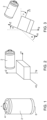
- Figure 1 is a schematic of an acceptable battery gravitational orientation in which the positive terminal of the battery is located on the top side of the battery in a vertical plane.
- Figure 2 is a schematic of another acceptable battery gravitational orientation in which the positive terminal of the battery is located in a horizontal plane.
- Figure 3 is a schematic of a problematic battery gravitational orientation in which the positive terminal of the battery is tilted down from a horizontal plane, causing a reduced battery life.
- the present invention is not limited to any theory as to the degradation of a battery lifetime upon its orientation relative to gravity being held or maintained under a sub-optimum orientation, the origin of the degradation is related to the cathode's location in a fixed area whereas the electrolyte (e.g., a mixture of zinc chloride and water or potassium hydroxide and water or thionyl chloride with an electrolyte salt) may fall or drain away from the cathode (the positive terminal) under the influence of gravity.
- the electrolyte e.g., a mixture of zinc chloride and water or potassium hydroxide and water or thionyl chloride with an electrolyte salt
- the lifetime of the battery with the uncovered electrode(s) is reduced because of the lack of the same available electrode area as compared to when the battery had the entire area of the electrodes covered.
- This problem of electrode(s) being uncovered under in the sub-optimum orientation typically is more severe with larger batteries which have larger empty spaces for the electrolyte to fall into.
- the battery orientation not result in an electrolyte disposition therein where the electrolyte uncovers a part of the electrodes.
- the battery housing may also be opaque.
- an accelerometer is fixed to the battery or the battery housing (or to the utility box).
- a processor in communication with the accelerometer determines if battery is in a sub-optimum orientation for battery life based on the gravity direction and a relative alignment of the gravity direction to the battery housing.
- the gravity direction is derived from a gravity vector calculated from measurements received from a three-axis accelerometer.
- Figures 2 and 3 illustrate how the three acceleration components yield a gravity vector, from which a direction of the gravity vector relative to the battery can be derived.
- the accelerometer is fixed to the battery housing, a direction of the gravity vector relative to the housing can be derived, from which the gravity direction relative to the battery can be derived. See Figures 6 and 7 and the description below.
- the gravity direction is derived from a single axis accelerometer that is aligned with the anode-cathode axis of the battery.
- a positive gravitation direction would mean that the positive side of the battery is pointed upwards, therefore acceptable.
- a negative gravitation direction would mean that the negative side of the battery is pointed upwards, therefore unacceptable.
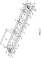
- FIG 4 is a schematic of an in-line multiple battery housing of the invention with a three-axis accelerometer disposed thereon.
- the battery housing 8 is similar to that described in U.S. Pat. No. 3,859,140 (the entire contents of which are incorporated herein in its entirety).
- Battery housing 8 in this embodiment includes a U-shaped rigid plastic trough 10 of an electrically insulating material having a curved bottom wall portion for conforming generally to the configuration of cylindrical battery cells 12.
- Trough 10 can have a pair of strengthening edge flanges extending along the side wall lips. Extending inwardly and upwardly from the inner surface of the trough side walls are optional opposing pairs of fingers 16 having lower curved surfaces for engaging and blocking the cylindrical battery cells 12 against removal from trough 10. While shown holding multiple battery cells 12, the battery housing of this type could be made such that it holds only one battery cell 12.
- Each end wall 18, 20 as shown can have a rectangular recess at 22 which is open to the interior of trough 10 and which extends to form a slot-like opening 23 at the top inner edge of wall 18, 20 forming the trough end lip 29.
- Each recess 22 can have a pair of opposing lip flanges 24 and 26 along the sides of the recess 22 defining opposing parallel grooves 28 and 30 extending to the opening 23.
- the recess 22 in end plate 18 can have a fixed contact in the form of an electrically conductive plate 32 having parallel edges snug fit in grooves 28 and 30 to secure plate 32 in a position for electrical contact with a top button contact of the battery cell 12.
- the recess 22 in end plate 20 can have an opposing electrical contact providing a snug fit in the grooves 28 and 30.
- Each recess 22 may also be provided with a bottom port 36 through which an extension or lead of the electrical contact 32 or 34 can project as seen at 38 for connection to external circuitry.
- the three-axis accelerometer is a part of processor 50 attached to the battery housing 8, although the accelerometer could be merely in communication with processor 50 and disposed on another part of the battery housing or fixed to the utility box.
- a processor such as processor 50 noted above is programmed to receive one or more signals from a accelerometer, compute a gravity vector from the one or more signals, derive a gravity direction from the gravity vector, and determine if battery is in a sub-optimum orientation for battery life based on a) the gravity direction and a relative alignment of the gravity direction to the battery housing, and b) knowledge of the battery deployment inside the housing 8.
- the battery housing of this invention can be different from the in-line configuration shown in Figure 4 .
- Figure 5 is a schematic of a paired battery housing of the invention upon which an accelerometer could be disposed thereon.
- the battery housing 8 shown in Figure 5 is similar to that described in U.S. Pat. No. 4,161,568 (the entire contents of which are incorporated herein in its entirety).
- the battery housing 8 may be formed of molded plastic, for example.
- battery housing 8 holds four conventional C-size battery cells 12. As is well known, such battery cells are generally cylindrical and have terminals of the polarities of each battery pointed in the same direction.
- the positive terminals 130 are buttons protruding from one end of the dry cells, and the negative terminals 132 are part of the opposite end of the dry cells.
- a pin and flange mechanism 55 secures the batteries once the batteries are placed in compartments 112 and 114.
- Each compartment 112 and 114 is provided with appropriate contacts for engaging adjacent battery terminals.
- a contact 134 is provided at one end of compartment 114 and a contact 136 is provided at the opposite end of compartment 112.
- a straight extension 140 of contact 136 may pass through a notch at one end of common side wall 120 and be electrically connected to the contacts.
- Contacts may be springs as shown or other metal posts or plates which make electrical contact to the battery posts. Contacts 134 and 136 ensure that the batteries are urged into engagement with one another and that electrical continuity between the contacts of the batteries is established.
- External lead structures, flange 46 and center tap 47 provide for an electrical connection through the housing 8. In this embodiment of the invention, the sub-optimal orientation would exist when any one of the cathodes of the batteries are pointed downward.
- a three-axis accelerometer is attached to side wall 118.
- a single-axis accelerometer is attached to side wall 118 and aligned parallel the longitudinal axis of the batteries.
- a positive gravitation direction would mean that the positive side of the battery is pointed upwards, therefore acceptable.
- a negative gravitation direction would mean that the negative side of the battery is pointed upwards, therefore unacceptable.
- gravitation-orientation refers to the orientation of battery's cathode or anode relative to the direction of gravity.
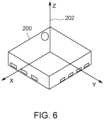
- FIG. 6 is a simplified schematic of a three-axis accelerometer 200 installed for example on a battery housing (not shown).
- the three-axis accelerometer 200 is represented schematically by the x-, y-, and z-axis vectors, with the z-axis enumerated as 202.
- a three-axis accelerometer can be used to detect acceleration in any direction. When the device is at rest, the only acceleration detected is that of gravity. Regardless of the orientation of the three-axis accelerometer 200, the gravity vector is 1g (9.8m/s 2 .)
- the gravity vector can be determined by looking at the magnitudes and polarities of the acceleration in each of the three axes, and optionally summing them through vector addition. In this manner, the exact orientation of the battery housing (or utility box if connected thereto in a fixed orientation) relative to gravity can be determined.
- Figure 7 is a schematic showing the resolving of the gravity vector along the three-axes of the three-axis accelerometer 200 shown in Figure 6 .
- the three-axis accelerometer provides a processor such as for example processor 50 in Figure 4 with the acceleration magnitudes along the x-axis, y-axis, and z-axis.
- the processor through vector addition (noted above) can determine the direction of gravity.
- the three-axis accelerometer 200 has a known orientation when mounted to the utility box, then the gravitational orientation of the utility box is known.
- the battery housing and battery orientation relative to the utility box is known, then the gravitational orientation of the batteries can be calculated.
- a similar calculation would follow if the three-axis accelerometer 200 were mounted with the z-axis off-normal to the utility box.
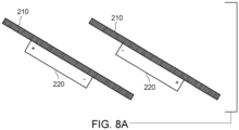
- Figure 8A is a schematic of a utility service line 210 (water, gas, fluid, electricity) with two gravitation-orientations of the batteries in utility box 220, one with the positive side terminal uphill of its negative side terminal (preferred) and one with the negative side terminal uphill of its positive side terminal (sub-optimum).
- the installer has another dilemma to resolve with regard to the proper installation of a utility box. That is for installation along a utility service line that is tilted, rotation of the utility box can change the battery's gravitation-orientation from preferred to non-preferred.
- Figure 8B is schematic perspective of utility service 240, a register 250, and an electronic counter 260 of a coupled to each other.
- the orientation of the batteries inside counter 260 is denoted by the "+" and "-" symbols thereon.
- Register 250 typically measures water, fluid, gas, or electrical flow and communicates with the electronic counter 260.
- a flow meter is attached to water register 250.
- a piezoelectric counter in the water register 250 produces output pulses from water flow through.
- the electronic counter 260 contain circuitry therein powered at least by batteries (not shown).
- the orientation of the batteries in electronic counter 260 is determined at the time of installation to see if the batteries are in an acceptable orientation.
- installation of utility service 240, a register 250, and an electronic counter 260 may occur without the batteries being installed at that time.
- the installer uses the gravitational orientation of the battery housing as the guide for proper installation. Late, when the batteries are installed, the gravitational orientation information can be verified.
- processor 50 provides a signal outside of the utility box 220 which is an indication of the battery's gravitation-orientation (or the battery housing's gravitational orientation), including whether the battery is in a sub-optimum gravitation-orientation or an acceptable gravitation orientation.
- a problematic installation that is when it turns out that the positive-side terminal is tilted downward, the installation can be halted, and the installer instructed to re-orient the utility box containing the battery.
- processor 50 determines that the battery is oriented in a sub-optimum orientation, a message is broadcast to either the installer or to a central server or both alerting personnel to the improper battery orientation. Alternatively, the message can be stored for later retrieval.
- Processor 50 is programmed with a conversion, given the uniquely fixed position of the three-axis accelerometer to the battery housing and/or the fixed orientation of the battery inside the battery housing (depending on the type of battery housing: in-line or paired).
- the measured gravity vector reveals the gravity direction and thus the battery gravitation orientation. If it is found that the battery is in a non-ideal orientation, processor 50 can send a message that the installation can be halted, and the installer instructed to re-orient the unit, as noted above.
- processor 50 can send a signal is transmitted to the utility server (or otherwise to another party) as validation of proper installation.
- FIG 8C is a schematic of a battery sleeve 225 (containing therein an accelerometer and a processor) in which the unit is directly attached to battery 230.
- the processor of battery sleeve 225 functions as the processors described above. In this embodiment, the processor only needs to be programmed with the relative orientation of the accelerometer to the longitudinal axis of the battery 230.
- a change in the orientation of the battery housing inside the utility box can be determined by comparing the current state of the three vectors with the originally captured state. In this embodiment, if the difference between the current state and the starting state exceeds a certain threshold, the unit can be considered tilted, and an alarm is triggered or a notification sent to the utility server.
- Meters are frequently installed and mounted in meter pans which are in turn mounted in fixed and rigid positions on utility poles or the sides of buildings.
- Several types of events can dislodge the meters or pans from their intended installation positions. Some of these events include vehicle collision, storms, earthquakes, and drought induced soil subsidence. Disturbance of the meters and their attached electrical wiring can result in electrical shorts, high temperature connections, and fires. Tampering with the meter by its removal from the socket by unauthorized personnel will also cause movement of the meter from its installation position. Remedial action taken based upon detection of this dislodging can mitigate further damage or loss of property.
- an internal processor can monitor the accelerometer for changes in position (translation in one or more of the three physical directions) or orientation (rotation in one or more of the three physical axis).
- the battery or battery housing gravitational orientation becomes a flag or status indicative of an untampered or a tampered state.
- the processor can take multiple actions.
- the processor could declare an alarm state. In this alarm state, the processor could cause the alarm to be reported on the meter's display if one is available, or if a communication channel is available if could report the alarm via the communication channel. It the meter has an internal service disconnect switch, the processor could disconnect service in the event of an alarm.
- the installation of the three axis accelerometer with the battery housing provides the capability to detect tampering or an environmental impact on a utility box. For example, by removing a register from a meter body, water could continue to flow but the register would no longer detect it. Accordingly, in one example, the three-axis accelerometer with the battery housing is installed in the register. Removal of the register would generate a change in the orientation vectors and alert the utility to the tampering event.
- the movement of the ground relative to the utility meter pulls the utility meter and typically twists the meter box gradually as the soil or ground subsides.
- processor 50 would detect a slow and gradual change in position or orientation of the accelerometer, the battery, the battery housing, or the utility box that exceeds a fixed or programmable threshold. The movement would distinguish from higher frequency tamper events or seismic shaking or weather conditions. Essentially, the processor would be programmed to track the average position per day (or other preprogrammed time period) and monitor the change in the average position. As before, the processor can take multiple actions. The processor could declare an alarm state. In this alarm state, the processor could cause the alarm to be reported on the meter's display if one is available, or if a communication channel is available if could report the alarm via the communication channel. It the meter has an internal service disconnect switch, the processor could disconnect service in the event of an alarm.
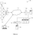
- Figure 9 depicts a communication system 100 by which for example the utility boxes 113 can communicate to a utility server 101 or to the installer via a controller 115.
- Utility server 101 can be coupled to a data center 103 that includes databases where acquired data from the three axis accelerometer or externally acquired data can be stored and optionally time-stamped.
- System 100 may be coupled via a firewall 105 to a wired or wireless network 111 which communicates to utility boxes 113.
- System 100 can also be accessed via protective firewalls 107 protecting a utility company's virtual private network 109.
- Bi-directional communication may occur between each utility box113 and system 100 via point of presence (POP) 115.
- POP point of presence
- Internet communication devices such as personal computer 117 (or smart phone) may access utility boxes 113 and system 100.
- the hardware design is not limiting of this invention, and may comprise the controller 115 with program memory, a liquid crystal display or other known displays; a directional sensing infra-red disk interface, an infrared data association (IrDA) communications port for diagnostics; non-volatile memory for data reading/ storage; a real-time clock for time stamping of data measurements; and a serial port to interface with various wired or wireless communication modules.
- Controller 115 which may be a mobile controller can include processor 50 or a functional equivalent thereof, such as a central processing unit (CPU) and/or at least one application specific processor (ASP).
- Controller 115 may include one or more circuits or be a circuit that utilizes a computer readable medium, such as a memory circuit (e.g., ROM, EPROM, EEPROM, flash memory, static memory, DRAM, SDRAM, and their equivalents), configured to control the processor to perform and/or control the processes and systems of this disclosure.
- a computer readable medium such as a memory circuit (e.g., ROM, EPROM, EEPROM, flash memory, static memory, DRAM, SDRAM, and their equivalents), configured to control the processor to perform and/or control the processes and systems of this disclosure.
- the computer readable medium can include the methods and algorithms discussed therein as well as gravitation-orientation log files.
- controller 50 may be a stationary work station monitored or monitorable by site personnel or remotely monitored by the utility provider.
- Each utility box 113 is capable of monitoring the gravitation-orientation in real time. Additionally, data such as utility usage readings, or high frequency vibrations, or long term orientation drifts can be taken at programmed predetermined intervals and can be stored in a non-volatile memory at the box 113 or the utility server 101. Each box 113 can periodically establish a link to system 100.
- the presence of the three-axis accelerometer in the utility box 113 permits the installer or utility provider to be provided with gravitation-orientation at the time of installation and at programmed report times or query times thereafter.
- the utility box 113 senses the gravitation-orientation and sends a signal to the installer's phone (or other network) that the utility box has been placed in an orientation with the battery in one of the preferred directions.
- the utility box having determined that its battery is placed in the proper direction sends a notification to the installer and then ceases communication with the installer or the utility server 101, unless the box is subsequently moved beyond some threshold value.
- An alert can be sent if the gravitation-orientation changes more than a preprogrammed amount, as a possible indication of tampering
- utility box 113 transmits a signal over a network to a central server that its battery position is not in the preferred orientation. At that point the utility can contact a service technician to correct the problem.
- utility box 113 senses that there is been substantial movement of the utility overtime. This movement might suggest that the installation placed the utility box 113 in an unstable situation, in which case the installer will be notified of the problem.
- the presence of the three-axis accelerometer in utility box 113 permits a recording over time of a change in the gravity vector. If this change is repetitive and indicative of excessive environmental vibrations, then the lifetime of the electronic equipment inside the utility box could be adversely affected. In this case, an alert can be provided to service personnel or a central server that the environmental conditions are not the most appropriate for the longevity of the utility box. Situations where this attribute may be most important is where the utility box is attached to a machine whose components are rotating at a significant speed. That is the utility box may be associated with an electric motor turning a reciprocating device or revolving device. Should the reciprocating device or the revolving device become unbalanced, vibrations will be transmitted to the utility box the utility box sensing the excessive vibration it can then alert a service person or a central router as to the vibrational disturbance.
- the network of utility boxes 113 shown in Figure 9 may be above ground on utility poles.
- Weather conditions such as wind and ice storms would result in the gravitation-orientation vectors changing over time.
- a processor in the utility box or the utility server measures a long-term drift in the orientation such as from the ground subsidence noted above.
- Alert conditions can be programmed when the long-term drift exceeds a threshold. Due the presence of short-term variations such as noted above, the average orientation is calculated for example on a weekly basis, and the averaged positions per week are then compared to a threshold to ascertain a long term change in orientation.
- a processor in utility box 113 (or utility server 101) is programmed to recognize and differentiate between at least one of seismic events or soil subsidence or weather events based on a temporal period of the disturbances.
- the network of utility boxes 113 shown in Figure 9 could sense and report seismic activity.
- the widespread adoption of utility boxes 113 with the three axis-axis accelerometers would result in a sensor network capable of monitoring the degree of movement of "standard" fixtures (telephone poles, building walls, underground walls). These sensors would then represent more accurate/direct measures of the effect of seismic activity than distributed Richter scale sensors measuring the strength of the earthquake from which the impact of which would be surmised.
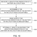
- FIG. 10 is a flowchart depicting a computerized method example.
- step 1001 measure a gravitation-orientation of a battery (or a battery housing) in a utility box.
- step 1005 issue a validation if the gravitation-orientation of the battery (or the battery housing) in the utility box is acceptable.
- the computerized method embodied for example in processor 50 can provide the installer or utility provider with gravitation-orientation at the time of installation and at programmed report times or query times thereafter.
- the computerized method can sense the gravitation-orientation and sends a signal to the installer's phone that the utility box has been placed in an orientation with the battery in one of the preferred directions or in a sub-optimum orientation.
- the computerized method embodied for example in processor 50 can store acquired data from the three axis accelerometer or externally acquired data. Regardless, the acquired data can be time-stamped. The computerized method can monitor the gravitation-orientation in real time. The computerized method can distinguish between high frequency vibrations or long term orientation drifts and provide appropriate alerts.
- the computerized method embodied for example in processor 50 can record over time of a change in the gravity vector.
- the computerized method can assess if this change is repetitive and indicative of excessive environmental vibrations. In that case, the computerized method can send an alert to service personnel or a central server that the environmental conditions are not the most appropriate for the longevity of the utility box.
- the computerized method can track the amount of displacements during adverse environmental conditions and alert the utility if a planned service interruption should be implemented prior to a catastrophic interruption of service.
- the computerized method can sense and report seismic activity.
Landscapes
- Engineering & Computer Science (AREA)
- General Chemical & Material Sciences (AREA)
- Manufacturing & Machinery (AREA)
- Chemical & Material Sciences (AREA)
- Chemical Kinetics & Catalysis (AREA)
- Electrochemistry (AREA)
- Microelectronics & Electronic Packaging (AREA)
- Physics & Mathematics (AREA)
- General Physics & Mathematics (AREA)
- Radar, Positioning & Navigation (AREA)
- Remote Sensing (AREA)
- Arrangements For Transmission Of Measured Signals (AREA)
- Secondary Cells (AREA)
Description
- This application claims priority to
U.S. Serial No. 15/928,630 filed March 22, 2018 - The present invention relates to a system and method for monitoring the status of utility boxes at the time of installation and while in service including a battery orientation of batteries in the utility boxes.
- In utility boxes, electrical connections may deteriorate for a variety of reasons, such as aging, harsh treatment, removal and insertion of a meter or operation in poor environments. A deteriorated electrical connection may exhibit increased temperature prior to catastrophic failure of the electrical connection. For example, if an electrical connection is oxidized or corroded, or if a mechanical deterioration (e.g., reduced spring force in the meter socket jaws) results in poor connection between contacts in an electrical connection, a resistance of the electrical connection may increase. When the resistance of an electrical connection increases, power dissipation and a corresponding thermal temperature of the electrical connection may likewise increase.
- Besides these environmental factors, tampering and improper installation can adversely affect the lifetime and longevity of utility boxes in service.
- The following patent documents (the contents of which are incorporated herein by reference in their entirety) describe techniques used prior to the present invention for monitoring the status of utility boxes at the time of installation and while in service.
-
U.S. Pat. 5,086,292 entitled "Tamper detection device for utility meter" describes a system for detection of tampering with a utility meter provides not only an indication that tampering has occurred but also sufficient information to enable an estimation of actual consumption to be made as opposed to the tampered metered consumption. The device in the '292 patent includes a plurality of tampering sensors sensing tilt, electric field, magnetic field, temperature, sound, reverse rotation of a moving element and excessive difference between metered consumption and an approximate actual consumption. -
U.S. Pat. 5,877,703 entitled "Utility meter transmitter assembly for subsurface installations" describes an improved assembly for housing electronics for remote reading of meter reading data in a subsurface enclosure includes a first inner enclosure of metal for housing the receiver/transmitter circuitry, a second inner enclosure for housing a battery and an outer enclosure of plastic which encloses both of the inner enclosures and additionally provides a sealed compartment for an antenna. -
U.S. Pat. 7,432,823 entitled "Tamper detection apparatus for electrical meters" describes a tamper detection apparatus for an electric meter installed at a facility supplied power through an electrical distribution system. A sensor of the '823 patent senses movement of the meter more than a predetermined amount with respect to the receptacle, whether or not electricity is flowing through the meter, and produces a tampering signal when this occurs. Generation of a tampering signal results in a tamper alert signal being transmitted to the system through a two-way communications path established between the facility and the system. -
U.S. Pat. 8.352,191 entitled "Seismic detection in electricity meters" describes an arrangement for recording seismic events includes an electricity meter sensor circuit, a digital processing circuit, and an accelerometer operably connected to the digital processing circuit. The accelerometer in the ` 191 patent is configured to provide signals representative of seismic information to the digital processing circuit. A memory in the ` 191 patent is configured to store data records relating to at least some of the seismic information. -
U.S. Pat. 8.754,634 entitled "System and method for tamper detection in a utility meter" describes systems and methods for detecting the removal of a meter cover are provided. For example, a tamper-detect energy meter may include metering circuitry, a processor, a tamper detect switch, and a cover with a switch interface surface. In the '634 patent, the tamper detect switch may be triggered from an open circuit state to a closed circuit state as the switch interface surface of the cover contacts the tamper detect switch during removal. -
U.S. Pat. 8.797,169 entitled "Systems and methods for sensing and indicating orientation of electrical equipment with passive cooling" describes a system for sensing and indicating orientation of electrical equipment comprises an orientation sensor and control logic. The control logic in the ` 169 patent is configured to compare predefined data with an orientation of the electrical equipment sensed by the orientation sensor in order to determine whether the sensed orientation of the equipment is within an acceptable range such that sufficient cooling by a cooling system is likely to occur. If the sensed orientation of the equipment is not within the acceptable range, the control logic in the ` 169 patent transmits a notification signal so that corrective action can occur. -
U.S. Pat. 8.978,443 entitled "Shock detection in a utility meter having reporting capability" describes an arrangement for use in a utility meter which includes an accelerometer, a processing circuit, and a source of power. The accelerometer in the '443 patent is configured to detect impact force on a utility meter housing. The processing circuit in the '443 patent is operably coupled to receive information representative of detected shock events from the accelerometer, and is configured to store information regarding detected shock events in a non-volatile memory. -
U.S. Pat. Appl. Publ. No. 2016/0351028 entitled "Tamper Detection In Utility Meters" describes devices to detect utility theft, as well as methods of their use. The devices in the '028 publication are utility meters that have a positioning detector; a microprocessor connected to receive readings from the positioning detector; a memory storage device in communication with the microprocessor, and at least one power source to provide power to the microprocessor and the memory storage device. Combining positioning readings with theft detection algorithms allows increased accuracy in the automated detection of theft, even when grid power is not available to power the accelerometer or compass. -
WO 2017/173221 A1 discloses a system for detecting gravitational orientation of a battery, comprising an accelerometer fixed relative to a battery and a battery housing including the battery, a processor programmed to receive one or more signals from the accelerometer and compute a gravity direction from the one or more signals and determine if the battery or the battery housing is in a storage mode orientation or operation mode orientation based at least on the gravity direction computed from the one or more signals from the accelerometer. -
US 2017/279164 A1 describes a network of gravitational orientation detectors, comprising a plurality of sensors with each sensor having a battery (cf. par. 27), an accelerometer fixed relative to the battery and a processor programmed to receive one or more signals from the accelerometer, and compute a gravity direction from the one or more signals. -
WO 2017/218679 A1 discloses a system for detecting gravitational orientation of a battery using an electronic gyroscope and a gravitational accelerometer delivering signals to a processor for determining the orientation of the battery with respect to gravity. -
FR 2 991 509 A1 - In one embodiment, there is provided a system for battery gravitational orientation detection, according to independent claim 1.
- In one embodiment, there is provided a method for battery gravitational orientation detection, according to
independent claim 8. - In one embodiment, there is provided a network of gravitational orientation detectors, according to claim 14.
- It is to be understood that both the foregoing general description of the invention and the following detailed description are exemplary, but are not restrictive of the invention.
- A more complete appreciation of the invention and many of the attendant advantages thereof will be readily obtained as the same becomes better understood by reference to the following detailed description when considered in connection with the accompanying drawing, wherein:
-
FIG. 1 is a schematic of a battery gravitational orientation in which the positive terminal of the battery is located on the top side of the battery in a vertical plane; -
FIG. 2 is a schematic of another acceptable battery orientation in which the positive terminal of the battery is located in a horizontal plane; -
FIG. 3 is a schematic of a problematic battery orientation in which the positive terminal of the battery is tilted down from a horizontal plane, causing a reduced battery life; -
FIG. 4 is a schematic depicting a battery housing with a three axis -axis accelerometer installed thereon; -
FIG. 5 is a schematic of another battery housing of the invention with a three-axis accelerometer disposed thereon; -
FIG. 6 is a simplified schematic of a three-axis accelerometer; -
FIG. 7 is a schematic showing the resolving of the gravity vector along the three-axes of the three-axis accelerometer; -
FIG. 8A is a schematic of a utility service with two gravitation-orientations of the battery in utility box; -
Figure 8B is schematic showing two orientations of a utility box coupled to a utility service line; -
Figure 8C is a schematic of a processor unit (containing therein an accelerometer and a processor) in which the unit is directly attached to a battery; -
FIG. 9 is a schematic of a communication system connecting utility boxes to a utility server or to an installer or a controller; and -
FIG 10 is a flowchart depicting an example of a method for battery gravitational orientation detection. - One problem that is faced by a utility is that of knowing the status of utility boxes at installation and after installation.
- A particular problem addressed by this invention is knowing the gravitational orientation of batteries installed in electronic equipment in positions underground or otherwise not accessible for long periods of time or else when having to access the installed positions would cause a significant downtime or expense to the gas, water, or electric utility. In this case, the electronic equipment installed in these remote (or otherwise inaccessible) positions has to operate as long as possible on the available battery life. In some cases, the battery life can be supplemented by an axillary power source such as 120 volts on an electric line or perhaps a solar cell or photoelectric converter. However, in many situations, the remote box is underground and not accessible to other power sources. Even if the batteries have access to other sources of power, a battery lifetime is dependent on the number of charge cycles. Therefore, having one cycle of battery discharge last as long as possible is advantageous.
- To extend battery life, electronic equipment is often designed to run on duty cycles and/or to run only after wake-up calls, which can conserve a battery's charge and prolong the battery lifetime. However, these measures do not serve to extend a battery's life in actual use charging or discharging. Rather, these measures merely extend the time before the battery dies.
- The inventors have realized that, since the battery life can be adversely affected by the gravitation-orientation of the battery, it was important to detect the battery orientation especially at the time of installation.
- According to the invention, a battery in the utility box contains a liquid (or fluid-type) electrolyte and because of its internal construction is sensitive to orientation. It is preferred to keep the positive terminal of the battery in an upright or horizontal position. If the positive terminal of the battery is pointing downward, the life of the battery can be greatly reduced.
- Accordingly, in one illustration example, there is provided a battery housing for example which can uniquely fix a direction of one or more batteries relative to the battery housing, an accelerometer attached to the battery or the battery housing, and a processor programmed to receive one or more signals from the accelerometer, compute a gravity direction (e.g., from a gravity vector) from the one or more signals, and determine if battery is in a sub-optimum orientation for battery life based on the gravity direction and a relative alignment of the gravity direction to the battery or the battery housing.
-
Figure 1 is a schematic of an acceptable battery gravitational orientation in which the positive terminal of the battery is located on the top side of the battery in a vertical plane.Figure 2 is a schematic of another acceptable battery gravitational orientation in which the positive terminal of the battery is located in a horizontal plane.Figure 3 is a schematic of a problematic battery gravitational orientation in which the positive terminal of the battery is tilted down from a horizontal plane, causing a reduced battery life. According to one embodiment of the invention, it is preferable to design a utility box where the battery installation is maintained in one of the preferred the directions and is not held or maintained in the adverse position with a cathode pointing in a downward direction. - While the present invention is not limited to any theory as to the degradation of a battery lifetime upon its orientation relative to gravity being held or maintained under a sub-optimum orientation, the origin of the degradation is related to the cathode's location in a fixed area whereas the electrolyte (e.g., a mixture of zinc chloride and water or potassium hydroxide and water or thionyl chloride with an electrolyte salt) may fall or drain away from the cathode (the positive terminal) under the influence of gravity. In a sub-optimum orientation, at the top of a battery cell, there is a space having an area of the anode and cathode not covered by the electrolyte. Under this arrangement, the lifetime of the battery with the uncovered electrode(s) is reduced because of the lack of the same available electrode area as compared to when the battery had the entire area of the electrodes covered. This problem of electrode(s) being uncovered under in the sub-optimum orientation typically is more severe with larger batteries which have larger empty spaces for the electrolyte to fall into. In general, because of this problem, one can expect the battery lifetimes to be reduced up to 40% in some battery designs upon improper gravitational alignment of the battery. Accordingly, it is preferable that the battery orientation not result in an electrolyte disposition therein where the electrolyte uncovers a part of the electrodes.
- While it may seem straightforward to ensure that the battery is in the proper orientation, because of the hidden aspect of the battery orientation inside the utility box being installed, there is no guarantee that the installer in the field has placed the utility itself in an orientation which preserves the battery orientation. For example, if the utility box is opaque, then the installer will not know the battery orientation inside the utility box. Furthermore, the battery housing may also be opaque.
- As noted above, an accelerometer is fixed to the battery or the battery housing (or to the utility box). A processor in communication with the accelerometer (typically but not necessarily a three-axis accelerometer) determines if battery is in a sub-optimum orientation for battery life based on the gravity direction and a relative alignment of the gravity direction to the battery housing.
- In one embodiment of the invention, the gravity direction is derived from a gravity vector calculated from measurements received from a three-axis accelerometer.
Figures 2 and 3 illustrate how the three acceleration components yield a gravity vector, from which a direction of the gravity vector relative to the battery can be derived. Furthermore, in one embodiment of the invention, the accelerometer is fixed to the battery housing, a direction of the gravity vector relative to the housing can be derived, from which the gravity direction relative to the battery can be derived. SeeFigures 6 and7 and the description below. - In one example, not part of the invention, the gravity direction is derived from a single axis accelerometer that is aligned with the anode-cathode axis of the battery. A positive gravitation direction would mean that the positive side of the battery is pointed upwards, therefore acceptable. Conversely, a negative gravitation direction would mean that the negative side of the battery is pointed upwards, therefore unacceptable.
-
Figure 4 is a schematic of an in-line multiple battery housing of the invention with a three-axis accelerometer disposed thereon. Thebattery housing 8 is similar to that described inU.S. Pat. No. 3,859,140 (the entire contents of which are incorporated herein in its entirety).Battery housing 8 in this embodiment includes a U-shaped rigidplastic trough 10 of an electrically insulating material having a curved bottom wall portion for conforming generally to the configuration ofcylindrical battery cells 12.Trough 10 can have a pair of strengthening edge flanges extending along the side wall lips. Extending inwardly and upwardly from the inner surface of the trough side walls are optional opposing pairs offingers 16 having lower curved surfaces for engaging and blocking thecylindrical battery cells 12 against removal fromtrough 10. While shown holdingmultiple battery cells 12, the battery housing of this type could be made such that it holds only onebattery cell 12. - Each
end wall trough 10 and which extends to form a slot-like opening 23 at the top inner edge ofwall trough end lip 29. Eachrecess 22 can have a pair of opposinglip flanges recess 22 defining opposingparallel grooves opening 23. - The
recess 22 inend plate 18 can have a fixed contact in the form of an electrically conductive plate 32 having parallel edges snug fit ingrooves battery cell 12. At the other end of the holder, therecess 22 inend plate 20 can have an opposing electrical contact providing a snug fit in thegrooves recess 22 may also be provided with abottom port 36 through which an extension or lead of theelectrical contact 32 or 34 can project as seen at 38 for connection to external circuitry. In one embodiment of the invention, the three-axis accelerometer is a part ofprocessor 50 attached to thebattery housing 8, although the accelerometer could be merely in communication withprocessor 50 and disposed on another part of the battery housing or fixed to the utility box. - In this embodiment of the invention, the sub-optimal orientation would exist when the cathode (button) of the
battery cell 12 is pointed downward. Thus, in one embodiment of this invention, a processor (such asprocessor 50 noted above) is programmed to receive one or more signals from a accelerometer, compute a gravity vector from the one or more signals, derive a gravity direction from the gravity vector, and determine if battery is in a sub-optimum orientation for battery life based on a) the gravity direction and a relative alignment of the gravity direction to the battery housing, and b) knowledge of the battery deployment inside thehousing 8. - In another embodiment, the battery housing of this invention can be different from the in-line configuration shown in
Figure 4 .Figure 5 is a schematic of a paired battery housing of the invention upon which an accelerometer could be disposed thereon. Thebattery housing 8 shown inFigure 5 is similar to that described inU.S. Pat. No. 4,161,568 (the entire contents of which are incorporated herein in its entirety). Thebattery housing 8 may be formed of molded plastic, for example. As shown,battery housing 8 holds four conventional C-size battery cells 12. As is well known, such battery cells are generally cylindrical and have terminals of the polarities of each battery pointed in the same direction. Thepositive terminals 130 are buttons protruding from one end of the dry cells, and thenegative terminals 132 are part of the opposite end of the dry cells. A pin andflange mechanism 55 secures the batteries once the batteries are placed incompartments 112 and 114. - Each
compartment 112 and 114 is provided with appropriate contacts for engaging adjacent battery terminals. Acontact 134 is provided at one end of compartment 114 and acontact 136 is provided at the opposite end ofcompartment 112. Astraight extension 140 ofcontact 136 may pass through a notch at one end ofcommon side wall 120 and be electrically connected to the contacts. Contacts may be springs as shown or other metal posts or plates which make electrical contact to the battery posts.Contacts flange 46 andcenter tap 47 provide for an electrical connection through thehousing 8. In this embodiment of the invention, the sub-optimal orientation would exist when any one of the cathodes of the batteries are pointed downward. - In one embodiment, a three-axis accelerometer is attached to
side wall 118. In another embodiment, a single-axis accelerometer is attached toside wall 118 and aligned parallel the longitudinal axis of the batteries. Here, as noted above, a positive gravitation direction would mean that the positive side of the battery is pointed upwards, therefore acceptable. Conversely, a negative gravitation direction would mean that the negative side of the battery is pointed upwards, therefore unacceptable. - As used herein, gravitation-orientation refers to the orientation of battery's cathode or anode relative to the direction of gravity.
-
Figure 6 is a simplified schematic of a three-axis accelerometer 200 installed for example on a battery housing (not shown). The three-axis accelerometer 200 is represented schematically by the x-, y-, and z-axis vectors, with the z-axis enumerated as 202. A three-axis accelerometer can be used to detect acceleration in any direction. When the device is at rest, the only acceleration detected is that of gravity. Regardless of the orientation of the three-axis accelerometer 200, the gravity vector is 1g (9.8m/s2.) The gravity vector can be determined by looking at the magnitudes and polarities of the acceleration in each of the three axes, and optionally summing them through vector addition. In this manner, the exact orientation of the battery housing (or utility box if connected thereto in a fixed orientation) relative to gravity can be determined. -
Figure 7 is a schematic showing the resolving of the gravity vector along the three-axes of the three-axis accelerometer 200 shown inFigure 6 . In one embodiment of the invention, the three-axis accelerometer provides a processor such as forexample processor 50 inFigure 4 with the acceleration magnitudes along the x-axis, y-axis, and z-axis. The processor through vector addition (noted above) can determine the direction of gravity. Assuming that the three-axis accelerometer 200 has a known orientation when mounted to the utility box, then the gravitational orientation of the utility box is known. Assuming that the battery housing and battery orientation relative to the utility box is known, then the gravitational orientation of the batteries can be calculated. A similar calculation would follow if the three-axis accelerometer 200 were mounted with the z-axis off-normal to the utility box. -
Figure 8A is a schematic of a utility service line 210 (water, gas, fluid, electricity) with two gravitation-orientations of the batteries inutility box 220, one with the positive side terminal uphill of its negative side terminal (preferred) and one with the negative side terminal uphill of its positive side terminal (sub-optimum). Here, the installer has another dilemma to resolve with regard to the proper installation of a utility box. That is for installation along a utility service line that is tilted, rotation of the utility box can change the battery's gravitation-orientation from preferred to non-preferred. -
Figure 8B is schematic perspective ofutility service 240, aregister 250, and anelectronic counter 260 of a coupled to each other. The orientation of the batteries insidecounter 260 is denoted by the "+" and "-" symbols thereon.Register 250 typically measures water, fluid, gas, or electrical flow and communicates with theelectronic counter 260. In one embodiment of the invention, a flow meter is attached towater register 250. A piezoelectric counter in thewater register 250 produces output pulses from water flow through. Theelectronic counter 260 contain circuitry therein powered at least by batteries (not shown). In one embodiment of the invention, the orientation of the batteries inelectronic counter 260 is determined at the time of installation to see if the batteries are in an acceptable orientation. As seen in the depictions inFigure 8B , there is a degree of freedom in rotating the electronic counter and register around theutility service 240. If the batteries inside theelectronic counter 260 are horizontally aligned, then the rotation around theutility service 240 presents no circumstance where the battery orientation is unacceptable. However, if theutility service 240 is mounted vertically as shown, then rotation of the electronic counter would in one circumstance have the cathodes pointed up (acceptable on right hand side) and in another circumstance have the cathodes pointed down (unacceptable on left hand side). - In one example, installation of
utility service 240, aregister 250, and anelectronic counter 260 may occur without the batteries being installed at that time. The installer uses the gravitational orientation of the battery housing as the guide for proper installation. Late, when the batteries are installed, the gravitational orientation information can be verified. - Accordingly, in one embodiment of the invention,
processor 50 provides a signal outside of theutility box 220 which is an indication of the battery's gravitation-orientation (or the battery housing's gravitational orientation), including whether the battery is in a sub-optimum gravitation-orientation or an acceptable gravitation orientation. In a problematic installation, that is when it turns out that the positive-side terminal is tilted downward, the installation can be halted, and the installer instructed to re-orient the utility box containing the battery. Thus, in one embodiment of the invention, whenprocessor 50 determines that the battery is oriented in a sub-optimum orientation, a message is broadcast to either the installer or to a central server or both alerting personnel to the improper battery orientation. Alternatively, the message can be stored for later retrieval. - More specifically, in the case where the utility box has been mounted, the magnitude and polarity of the vectors are first captured.
Processor 50 is programmed with a conversion, given the uniquely fixed position of the three-axis accelerometer to the battery housing and/or the fixed orientation of the battery inside the battery housing (depending on the type of battery housing: in-line or paired). The measured gravity vector reveals the gravity direction and thus the battery gravitation orientation. If it is found that the battery is in a non-ideal orientation,processor 50 can send a message that the installation can be halted, and the installer instructed to re-orient the unit, as noted above. In one embodiment of the invention, after installation and confirmation of an acceptable battery gravitation orientation,processor 50 can send a signal is transmitted to the utility server (or otherwise to another party) as validation of proper installation. -
Figure 8C is a schematic of a battery sleeve 225 (containing therein an accelerometer and a processor) in which the unit is directly attached tobattery 230. The processor ofbattery sleeve 225 functions as the processors described above. In this embodiment, the processor only needs to be programmed with the relative orientation of the accelerometer to the longitudinal axis of thebattery 230. - In one embodiment of the invention, by capturing the magnitude and polarity of the gravitational vectors when the device is first installed, a change in the orientation of the battery housing inside the utility box (and likewise a change in the orientation of the utility box) can be determined by comparing the current state of the three vectors with the originally captured state. In this embodiment, if the difference between the current state and the starting state exceeds a certain threshold, the unit can be considered tilted, and an alarm is triggered or a notification sent to the utility server.
- Because only the difference between initial and current state is used in this calculation, the starting orientation of the utility box is not needed. In other words, a tilt event can be detected regardless of the initial orientation of the utility box or the battery housing. This provides an advantage over mechanical sensors which are designed to be installed in a given orientation.
- Meters are frequently installed and mounted in meter pans which are in turn mounted in fixed and rigid positions on utility poles or the sides of buildings. Several types of events can dislodge the meters or pans from their intended installation positions. Some of these events include vehicle collision, storms, earthquakes, and drought induced soil subsidence. Disturbance of the meters and their attached electrical wiring can result in electrical shorts, high temperature connections, and fires. Tampering with the meter by its removal from the socket by unauthorized personnel will also cause movement of the meter from its installation position. Remedial action taken based upon detection of this dislodging can mitigate further damage or loss of property. By adding a multiple axis accelerometer to the internal circuitry of a meter (or in general to a utility box), an internal processor can monitor the accelerometer for changes in position (translation in one or more of the three physical directions) or orientation (rotation in one or more of the three physical axis). In this embodiment, the battery or battery housing gravitational orientation becomes a flag or status indicative of an untampered or a tampered state.
- If the internal processor detects a change in position or orientation that exceeds a fixed or programmable threshold, the processor can take multiple actions. The processor could declare an alarm state. In this alarm state, the processor could cause the alarm to be reported on the meter's display if one is available, or if a communication channel is available if could report the alarm via the communication channel. It the meter has an internal service disconnect switch, the processor could disconnect service in the event of an alarm.
- In one example, the installation of the three axis accelerometer with the battery housing provides the capability to detect tampering or an environmental impact on a utility box. For example, by removing a register from a meter body, water could continue to flow but the register would no longer detect it. Accordingly, in one example, the three-axis accelerometer with the battery housing is installed in the register. Removal of the register would generate a change in the orientation vectors and alert the utility to the tampering event.
- In parts of Canada recently, drought induced soil subsidence has placed stress on utility meters attached to buildings, in particular stress at the electrical joints/connections connecting the utility lines to the meter. Fires at these stressed electrical joints/connections are possible.
- The movement of the ground relative to the utility meter pulls the utility meter and typically twists the meter box gradually as the soil or ground subsides.
- Here, in the present example,
processor 50 would detect a slow and gradual change in position or orientation of the accelerometer, the battery, the battery housing, or the utility box that exceeds a fixed or programmable threshold. The movement would distinguish from higher frequency tamper events or seismic shaking or weather conditions. Essentially, the processor would be programmed to track the average position per day (or other preprogrammed time period) and monitor the change in the average position. As before, the processor can take multiple actions. The processor could declare an alarm state. In this alarm state, the processor could cause the alarm to be reported on the meter's display if one is available, or if a communication channel is available if could report the alarm via the communication channel. It the meter has an internal service disconnect switch, the processor could disconnect service in the event of an alarm. - In accordance with an example,
Figure 9 depicts acommunication system 100 by which for example theutility boxes 113 can communicate to autility server 101 or to the installer via acontroller 115.Utility server 101 can be coupled to adata center 103 that includes databases where acquired data from the three axis accelerometer or externally acquired data can be stored and optionally time-stamped. -
System 100 may be coupled via afirewall 105 to a wired orwireless network 111 which communicates toutility boxes 113.System 100 can also be accessed viaprotective firewalls 107 protecting a utility company's virtualprivate network 109. Bi-directional communication may occur between each utility box113 andsystem 100 via point of presence (POP) 115. In addition, Internet communication devices such as personal computer 117 (or smart phone) may accessutility boxes 113 andsystem 100. - The hardware design is not limiting of this invention, and may comprise the
controller 115 with program memory, a liquid crystal display or other known displays; a directional sensing infra-red disk interface, an infrared data association (IrDA) communications port for diagnostics; non-volatile memory for data reading/ storage; a real-time clock for time stamping of data measurements; and a serial port to interface with various wired or wireless communication modules.Controller 115 which may be a mobile controller can includeprocessor 50 or a functional equivalent thereof, such as a central processing unit (CPU) and/or at least one application specific processor (ASP). Controller 115 (or processor 50) may include one or more circuits or be a circuit that utilizes a computer readable medium, such as a memory circuit (e.g., ROM, EPROM, EEPROM, flash memory, static memory, DRAM, SDRAM, and their equivalents), configured to control the processor to perform and/or control the processes and systems of this disclosure. The computer readable medium can include the methods and algorithms discussed therein as well as gravitation-orientation log files. - In one embodiment of the invention, instructions from
processor 50 regarding the battery gravitational orientation is transmitted tomobile controller 115 for communication to an installer or service technicians. In a complex where there are multiple utility boxes of the present invention,controller 50 may be a stationary work station monitored or monitorable by site personnel or remotely monitored by the utility provider. - Each
utility box 113 is capable of monitoring the gravitation-orientation in real time. Additionally, data such as utility usage readings, or high frequency vibrations, or long term orientation drifts can be taken at programmed predetermined intervals and can be stored in a non-volatile memory at thebox 113 or theutility server 101. Eachbox 113 can periodically establish a link tosystem 100. - In one embodiment of the invention, the presence of the three-axis accelerometer in the
utility box 113 permits the installer or utility provider to be provided with gravitation-orientation at the time of installation and at programmed report times or query times thereafter. - In one embodiment of the invention, the
utility box 113 senses the gravitation-orientation and sends a signal to the installer's phone (or other network) that the utility box has been placed in an orientation with the battery in one of the preferred directions. In one embodiment of the invention, the utility box having determined that its battery is placed in the proper direction sends a notification to the installer and then ceases communication with the installer or theutility server 101, unless the box is subsequently moved beyond some threshold value. An alert can be sent if the gravitation-orientation changes more than a preprogrammed amount, as a possible indication of tampering - In one embodiment of the invention,
utility box 113 transmits a signal over a network to a central server that its battery position is not in the preferred orientation. At that point the utility can contact a service technician to correct the problem. - In one embodiment of the invention,
utility box 113 senses that there is been substantial movement of the utility overtime. This movement might suggest that the installation placed theutility box 113 in an unstable situation, in which case the installer will be notified of the problem. - In one embodiment of the invention, the presence of the three-axis accelerometer in
utility box 113 permits a recording over time of a change in the gravity vector. If this change is repetitive and indicative of excessive environmental vibrations, then the lifetime of the electronic equipment inside the utility box could be adversely affected. In this case, an alert can be provided to service personnel or a central server that the environmental conditions are not the most appropriate for the longevity of the utility box. Situations where this attribute may be most important is where the utility box is attached to a machine whose components are rotating at a significant speed. That is the utility box may be associated with an electric motor turning a reciprocating device or revolving device. Should the reciprocating device or the revolving device become unbalanced, vibrations will be transmitted to the utility box the utility box sensing the excessive vibration it can then alert a service person or a central router as to the vibrational disturbance. - In another example, the network of
utility boxes 113 shown inFigure 9 may be above ground on utility poles. Weather conditions such as wind and ice storms would result in the gravitation-orientation vectors changing over time. By tracking the amount of displacements during those adverse environmental conditions, planned service interruptions could be implemented prior to catastrophic interruption of service. By contrast, in one embodiment of the invention, a processor in the utility box or the utility server measures a long-term drift in the orientation such as from the ground subsidence noted above. Alert conditions can be programmed when the long-term drift exceeds a threshold. Due the presence of short-term variations such as noted above, the average orientation is calculated for example on a weekly basis, and the averaged positions per week are then compared to a threshold to ascertain a long term change in orientation. In one embodiment of the invention, a processor in utility box 113 (or utility server 101) is programmed to recognize and differentiate between at least one of seismic events or soil subsidence or weather events based on a temporal period of the disturbances. - In another example, the network of
utility boxes 113 shown inFigure 9 could sense and report seismic activity. In one embodiment of the invention, in earthquake zones, the widespread adoption ofutility boxes 113 with the three axis-axis accelerometers would result in a sensor network capable of monitoring the degree of movement of "standard" fixtures (telephone poles, building walls, underground walls). These sensors would then represent more accurate/direct measures of the effect of seismic activity than distributed Richter scale sensors measuring the strength of the earthquake from which the impact of which would be surmised. -
FIG. 10 is a flowchart depicting a computerized method example. - At
step 1001, measure a gravitation-orientation of a battery (or a battery housing) in a utility box. At step 1002, determine if the gravitation-orientation of the battery in the utility box is acceptable. Atstep 1003, issue an alert if the gravitation-orientation of the battery (or the battery housing) in the utility box is unacceptable. Optionally, atstep 1005, issue a validation if the gravitation-orientation of the battery (or the battery housing) in the utility box is acceptable. - The computerized method embodied for example in
processor 50 can provide the installer or utility provider with gravitation-orientation at the time of installation and at programmed report times or query times thereafter. The computerized method can sense the gravitation-orientation and sends a signal to the installer's phone that the utility box has been placed in an orientation with the battery in one of the preferred directions or in a sub-optimum orientation. - The computerized method embodied for example in
processor 50 can store acquired data from the three axis accelerometer or externally acquired data. Regardless, the acquired data can be time-stamped. The computerized method can monitor the gravitation-orientation in real time. The computerized method can distinguish between high frequency vibrations or long term orientation drifts and provide appropriate alerts. - The computerized method embodied for example in
processor 50 can record over time of a change in the gravity vector. The computerized method can assess if this change is repetitive and indicative of excessive environmental vibrations. In that case, the computerized method can send an alert to service personnel or a central server that the environmental conditions are not the most appropriate for the longevity of the utility box. - The computerized method can track the amount of displacements during adverse environmental conditions and alert the utility if a planned service interruption should be implemented prior to a catastrophic interruption of service. The computerized method can sense and report seismic activity.
- Numerous modifications and variations of the present invention are possible in light of the above teachings. It is therefore to be understood that within the scope of the appended claims, the invention may be practiced otherwise than as specifically described herein.
Claims (14)
- A system for battery gravitational orientation detection, comprising:an accelerometer (200) fixed relative to a battery (12) or a battery housing (8) including the battery (12), wherein the battery (12) contains a liquid or fluid-type electrolyte;wherein the accelerometer (200) is attached to a utility box (113) having therein the battery (12) or battery housing (8) and is oriented in a fixed direction relative to the battery (12) or the battery housing (8); a processor (50) programmed toreceive, from the accelerometer (200), one or more signals at a time of installation of the utility box (113) and at a subsequent report time that each indicate a direction of gravity vector,compute a change of gravity direction between the time of installation and the subsequent report time based on each of the indicated direction of gravity vector, anddetermine whether the battery (12) or the battery housing (8) is moved to a sub-optimum battery life orientation with the cathode of the battery tilted downward from a horizontal plane based on the computed change of gravity direction being more than a preprogrammed amount and on the fixed orientation of the accelerometer (200) relative to the battery (12) or battery housing (8).
- The system of claim 1, wherein the processor is programmed to communicate the sub-optimum battery life orientation to a field technician or a utility provider.
- The system of claim 1, wherein the battery of the battery housing has a preset orientation relative to the utility box.
- The system of claim 1, wherein the processor is programmed to communicate a change in orientation of the battery or battery housing after installation to a utility provider.
- The system of claim 1, wherein the accelerometer is a three-axis accelerometer configured to provide signals to the processor related to a first direction of gravity.
- The system of claim 5, wherein:the processor is programmed to convert the first direction of gravity for the accelerometer into a second direction of gravity for the battery or the battery housing, andthe processor is programmed to associate the second direction of gravity with a battery gravitational orientation.
- The system of claim 6, wherein the processor is programmed to at least one of store an alert and transmit the alert when the battery or the battery housing is in the sub-optimum orientation, orthe processor is programmed to at least one of store a status confirmation and transmit the status confirmation when the battery or the battery housing is in a proper orientation, orthe processor stores chronologically at least one of the first direction of gravity or the second direction of gravity, orthe processor transmits an alert when changes in at least one of the first direction of gravity or the second direction of gravity exceeds a threshold.
- The system of claim 1, wherein the accelerometer is attached to the battery housing and is oriented in a fixed direction relative to the battery housing.
- The system of claim 1, wherein the sub-optimum orientation for battery life comprises a cathode of one of the batteries tilted downward by more than a programmed percentage from the horizontal plane.
- The system of claim 1, wherein the processor comprises circuitry for registering gas or liquid fluid flow through a meter and communicating the fluid flow to a utility provider.
- The system of claim 1, wherein:the accelerometer is configured to provide one or more signals representative of an orientation of the battery or the battery housing relative to gravity; andthe processor is programmed to:store the one or more signals at a time of installation of the utility box having the battery or the battery housing,compare the one or more signals at the time of installation to subsequent signals from the accelerometer, andthereby detect a change in the orientation of the battery or the battery housing.
- The system of claim 11, wherein the processor comprises circuitry for at least one of storing the change in orientation and communicating the change in orientation to a utility provider.
- A method using the system of claim 1 for battery gravitational orientation detection, comprising:using the accelerometer (200) to generate one or more signals at a time of installation of the utility box (113) and at a subsequent report time that each indicate a direction of gravity vector,computing a change of gravity direction between the time of installation and the subsequent report time based on each of the indicated direction of gravity vector,determining whether the battery (12) or the battery housing (8)is moved to a sub-optimum battery life orientation with the cathode of the battery tilted downward from a horizontal plane, based on the computed change of gravity direction being more than a preprogrammed amount and on the fixed orientation of the accelerometer (200) relative to the battery (12) or battery housing (8); andissuing an alert in response to determining that the battery (12) or the battery housing (8) is moved to a sub-optimum battery life orientation.
- A network of gravitational orientation detectors, comprising:a plurality of systems for battery gravitational orientation detection according to anyone of claims 1 to 12,a wired or wireless communication network (111),a utility server (101) in communication with the plurality of systems via a controller (115) and a firewall (105) through the communication network (111).
Applications Claiming Priority (2)
| Application Number | Priority Date | Filing Date | Title |
|---|---|---|---|
| US15/928,630 US10916815B2 (en) | 2018-03-22 | 2018-03-22 | Battery orientation system |
| PCT/US2019/023508 WO2019183434A1 (en) | 2018-03-22 | 2019-03-22 | Battery orientation system |
Publications (4)
| Publication Number | Publication Date |
|---|---|
| EP3752893A1 EP3752893A1 (en) | 2020-12-23 |
| EP3752893A4 EP3752893A4 (en) | 2021-12-01 |
| EP3752893B1 true EP3752893B1 (en) | 2024-12-25 |
| EP3752893C0 EP3752893C0 (en) | 2024-12-25 |
Family
ID=67985620
Family Applications (1)
| Application Number | Title | Priority Date | Filing Date |
|---|---|---|---|
| EP19771247.4A Active EP3752893B1 (en) | 2018-03-22 | 2019-03-22 | Battery orientation system |
Country Status (5)
| Country | Link |
|---|---|
| US (1) | US10916815B2 (en) |
| EP (1) | EP3752893B1 (en) |
| CA (1) | CA3094362A1 (en) |
| MX (1) | MX2020009603A (en) |
| WO (1) | WO2019183434A1 (en) |
Families Citing this family (3)
| Publication number | Priority date | Publication date | Assignee | Title |
|---|---|---|---|---|
| US10916815B2 (en) * | 2018-03-22 | 2021-02-09 | Sensus Spectrum, Llc | Battery orientation system |
| US20220200070A1 (en) * | 2020-12-23 | 2022-06-23 | Brunswick Corporation | Marine battery with water ingress and shock detection |
| KR20220148006A (en) * | 2021-04-28 | 2022-11-04 | 현대자동차주식회사 | System and method for battery module alignment inspection |
Family Cites Families (36)
| Publication number | Priority date | Publication date | Assignee | Title |
|---|---|---|---|---|
| US5086292A (en) * | 1989-10-31 | 1992-02-04 | Iris Systems Inc. | Tamper detection device for utility meter |
| US5107203A (en) * | 1990-11-26 | 1992-04-21 | Schlumberger Industries Inc. | Sealed utility meter having internal automatic disconnection |
| US5994892A (en) * | 1996-07-31 | 1999-11-30 | Sacramento Municipal Utility District | Integrated circuit design automatic utility meter: apparatus & method |
| US5877703A (en) | 1997-08-12 | 1999-03-02 | Badger Meter, Inc. | Utility meter transmitter assembly for subsurface installations |
| CA2304250C (en) | 1997-12-24 | 2005-02-08 | Abb Power T & D Company Inc. | Method and apparatus for detecting and reporting a power outage |
| US6205867B1 (en) | 1998-10-07 | 2001-03-27 | American Electric Power, Inc. | Power line sag monitor |
| US7432823B2 (en) | 2005-11-09 | 2008-10-07 | Distribution Control Systems, Inc. | Tamper detection apparatus for electrical meters |
| US8970393B2 (en) * | 2006-03-31 | 2015-03-03 | Itron, Inc. | Data analysis system, such as a theft scenario analysis system for automated utility metering |
| US8352191B2 (en) | 2009-01-02 | 2013-01-08 | Landis+Gyr, Inc. | Seismic detection in electricity meters |
| US9933146B2 (en) * | 2009-01-16 | 2018-04-03 | Mag Instrument, Inc. | Portable lighting devices |
| US20100273041A1 (en) | 2009-04-24 | 2010-10-28 | Gm Global Technology Operations, Inc. | Temperature management system |
| KR101097248B1 (en) * | 2009-10-26 | 2011-12-21 | 삼성에스디아이 주식회사 | Protection circuit and protection method of battery pack, and an electronic bicycle |
| US20110161136A1 (en) | 2009-11-25 | 2011-06-30 | Patrick Faith | Customer mapping using mobile device with an accelerometer |
| WO2011123808A2 (en) * | 2010-04-02 | 2011-10-06 | Boston-Power, Inc. | Battery pack safety techniques |
| US20120016544A1 (en) | 2010-07-14 | 2012-01-19 | Sinoelectric Powertrain Corporation | Electric vehicle rollover detection system and method |
| US8978443B2 (en) | 2010-09-02 | 2015-03-17 | Landis+Gyr Inc. | Shock detection in a utility meter having reporting capability |
| US8322215B2 (en) * | 2010-09-13 | 2012-12-04 | Itron, Inc. | Accelerometer based removal and inversion tamper detection and tap switch feature |
| US20120259567A1 (en) * | 2011-04-07 | 2012-10-11 | 9058-5878 Québec Inc. (Video Assist) | Intelligent battery pack |
| US8797169B1 (en) | 2011-04-14 | 2014-08-05 | Adtran, Inc. | Systems and methods for sensing and indicating orientation of electrical equipment with passive cooling |
| US8730042B2 (en) * | 2011-10-05 | 2014-05-20 | General Electric Company | Systems and methods for detecting tampering associated with a utility meter |
| US9121883B2 (en) * | 2011-10-14 | 2015-09-01 | Landis+Gyr, Inc. | Magnetic tampering detection and correction in a utility meter |
| US20130110426A1 (en) * | 2011-11-02 | 2013-05-02 | General Electric Company | Energy meter interface system and method |
| US8754634B2 (en) | 2011-11-14 | 2014-06-17 | General Electric Company | System and method for tamper detection in a utility meter |
| TW201349627A (en) * | 2012-05-31 | 2013-12-01 | Emerald Battery Technologies Co Ltd | Battery monitoring and protection device and system and method thereof |
| US9344151B2 (en) * | 2012-11-21 | 2016-05-17 | Facebook, Inc. | Power line communication monitor |
| US9671254B2 (en) * | 2014-09-18 | 2017-06-06 | Mueller International, Llc | Magnetic sensing to detect tampering with a utility meter |
| US11033694B2 (en) | 2014-09-22 | 2021-06-15 | Koninklijke Philips N.V. | Inhaler with orientation sensor |
| US9893535B2 (en) | 2015-02-13 | 2018-02-13 | Energous Corporation | Systems and methods for determining optimal charging positions to maximize efficiency of power received from wirelessly delivered sound wave energy |
| US10326171B2 (en) * | 2016-03-24 | 2019-06-18 | Flow-Rite Controls, Ltd. | Intelligent monitoring systems for liquid electrolyte batteries |
| WO2017173221A1 (en) | 2016-03-31 | 2017-10-05 | Elitise Llc | Battery module with orientation detection for alternate operative states |
| US20160351028A1 (en) * | 2016-04-12 | 2016-12-01 | Neptune Technology Group Inc. | Tamper Detection In Utility Meters |
| KR102795944B1 (en) * | 2016-06-14 | 2025-04-16 | 존 이. 워터스 | Battery modules and systems for remote command and control of same |
| US11182987B2 (en) * | 2018-02-08 | 2021-11-23 | Geotab Inc. | Telematically providing remaining effective life indications for operational vehicle components |
| US10916815B2 (en) * | 2018-03-22 | 2021-02-09 | Sensus Spectrum, Llc | Battery orientation system |
| US10628706B2 (en) * | 2018-05-11 | 2020-04-21 | Ambient AI, Inc. | Systems and methods for intelligent and interpretive analysis of sensor data and generating spatial intelligence using machine learning |
| MX2019009277A (en) * | 2018-08-06 | 2020-02-07 | Tti Macao Commercial Offshore Ltd | Battery pack including a battery pack black box. |
-
2018
- 2018-03-22 US US15/928,630 patent/US10916815B2/en active Active
-
2019
- 2019-03-22 WO PCT/US2019/023508 patent/WO2019183434A1/en not_active Ceased
- 2019-03-22 MX MX2020009603A patent/MX2020009603A/en unknown
- 2019-03-22 CA CA3094362A patent/CA3094362A1/en active Pending
- 2019-03-22 EP EP19771247.4A patent/EP3752893B1/en active Active
Also Published As
| Publication number | Publication date |
|---|---|
| MX2020009603A (en) | 2020-10-07 |
| WO2019183434A1 (en) | 2019-09-26 |
| EP3752893A4 (en) | 2021-12-01 |
| US10916815B2 (en) | 2021-02-09 |
| EP3752893C0 (en) | 2024-12-25 |
| EP3752893A1 (en) | 2020-12-23 |
| US20190296404A1 (en) | 2019-09-26 |
| CA3094362A1 (en) | 2019-09-26 |
Similar Documents
| Publication | Publication Date | Title |
|---|---|---|
| US10401169B2 (en) | Enhanced power transmission tower condition monitoring system for overhead power systems | |
| EP3752893B1 (en) | Battery orientation system | |
| US20190166413A1 (en) | Monitor for Underground Infrastructure | |
| JP6350665B2 (en) | Sensor module and manhole information collection processing system | |
| US20070103334A1 (en) | Tamper detection apparatus for electrical meters | |
| JP5156503B2 (en) | Measuring system and inclinometer | |
| JP6268893B2 (en) | Level detection device and level monitoring system | |
| JP5270232B2 (en) | Measuring system and inclinometer | |
| US8352191B2 (en) | Seismic detection in electricity meters | |
| CN110346415A (en) | Pile local scour based on optics and electricity in situ monitors system | |
| CN206133045U (en) | Rain gage bucket is from detecting system | |
| US20220099704A1 (en) | Cable harness and asset indicator device for a data communication sensing and monitoring system | |
| CN215003745U (en) | Water supply pipeline marking device based on wisdom is patrolled and examined | |
| EP3824254B1 (en) | System, method, and computer program product for wake up of a water meter | |
| EP4121785B1 (en) | Electric meter installation issue detection based on orientation change | |
| EP3752842B1 (en) | Cut wire detection system, method, and computer program product | |
| KR20000071948A (en) | Remote magnetism pluviometer using PCS Network | |
| CN223871112U (en) | Intelligent water immersion and external damage monitoring and early warning intelligent device based on wireless narrowband communication | |
| CN220121321U (en) | Gas monitoring equipment | |
| CN109184791A (en) | A kind of underground engineering and deep basal pit pre-warning system for monitoring | |
| KR200356868Y1 (en) | Remote metering device for detecting pulse signal with real-time | |
| US20240304920A1 (en) | Intrinsically-safe battery assembly for wireless field devices | |
| CN108399444A (en) | A kind of cabinet equipment positioning system and method | |
| CN109254260B (en) | Recovery meter calibration and detection device and calibration and detection method used in substation | |
| PL224540B1 (en) | Detector to detect changes in location of the equipment elements, preferably the sanitary manhole covers |
Legal Events
| Date | Code | Title | Description |
|---|---|---|---|
| STAA | Information on the status of an ep patent application or granted ep patent |
Free format text: STATUS: THE INTERNATIONAL PUBLICATION HAS BEEN MADE |
|
| PUAI | Public reference made under article 153(3) epc to a published international application that has entered the european phase |
Free format text: ORIGINAL CODE: 0009012 |
|
| STAA | Information on the status of an ep patent application or granted ep patent |
Free format text: STATUS: REQUEST FOR EXAMINATION WAS MADE |
|
| 17P | Request for examination filed |
Effective date: 20200914 |
|
| AK | Designated contracting states |
Kind code of ref document: A1 Designated state(s): AL AT BE BG CH CY CZ DE DK EE ES FI FR GB GR HR HU IE IS IT LI LT LU LV MC MK MT NL NO PL PT RO RS SE SI SK SM TR |
|
| AX | Request for extension of the european patent |
Extension state: BA ME |
|
| DAV | Request for validation of the european patent (deleted) | ||
| DAX | Request for extension of the european patent (deleted) | ||
| REG | Reference to a national code |
Ref country code: DE Ref legal event code: R079 Free format text: PREVIOUS MAIN CLASS: G06F0001260000 Ipc: G01C0009060000 Ref document number: 602019063977 Country of ref document: DE |
|
| A4 | Supplementary search report drawn up and despatched |
Effective date: 20211103 |
|
| RIC1 | Information provided on ipc code assigned before grant |
Ipc: H01H 35/02 20060101ALI20211027BHEP Ipc: H01H 35/00 20060101ALI20211027BHEP Ipc: G06F 1/26 20060101ALI20211027BHEP Ipc: H01M 10/48 20060101ALI20211027BHEP Ipc: H01M 10/42 20060101ALI20211027BHEP Ipc: G01C 9/06 20060101AFI20211027BHEP |
|
| STAA | Information on the status of an ep patent application or granted ep patent |
Free format text: STATUS: EXAMINATION IS IN PROGRESS |
|
| 17Q | First examination report despatched |
Effective date: 20231123 |
|
| GRAP | Despatch of communication of intention to grant a patent |
Free format text: ORIGINAL CODE: EPIDOSNIGR1 |
|
| STAA | Information on the status of an ep patent application or granted ep patent |
Free format text: STATUS: GRANT OF PATENT IS INTENDED |
|
| INTG | Intention to grant announced |
Effective date: 20240716 |
|
| GRAS | Grant fee paid |
Free format text: ORIGINAL CODE: EPIDOSNIGR3 |
|
| GRAA | (expected) grant |
Free format text: ORIGINAL CODE: 0009210 |
|
| STAA | Information on the status of an ep patent application or granted ep patent |
Free format text: STATUS: THE PATENT HAS BEEN GRANTED |
|
| AK | Designated contracting states |
Kind code of ref document: B1 Designated state(s): AL AT BE BG CH CY CZ DE DK EE ES FI FR GB GR HR HU IE IS IT LI LT LU LV MC MK MT NL NO PL PT RO RS SE SI SK SM TR |
|
| REG | Reference to a national code |
Ref country code: GB Ref legal event code: FG4D |
|
| REG | Reference to a national code |
Ref country code: CH Ref legal event code: EP |
|
| REG | Reference to a national code |
Ref country code: DE Ref legal event code: R096 Ref document number: 602019063977 Country of ref document: DE |
|
| REG | Reference to a national code |
Ref country code: IE Ref legal event code: FG4D |
|
| U01 | Request for unitary effect filed |
Effective date: 20250115 |
|
| U07 | Unitary effect registered |
Designated state(s): AT BE BG DE DK EE FI FR IT LT LU LV MT NL PT RO SE SI Effective date: 20250121 |
|
| PG25 | Lapsed in a contracting state [announced via postgrant information from national office to epo] |
Ref country code: HR Free format text: LAPSE BECAUSE OF FAILURE TO SUBMIT A TRANSLATION OF THE DESCRIPTION OR TO PAY THE FEE WITHIN THE PRESCRIBED TIME-LIMIT Effective date: 20241225 |
|
| PG25 | Lapsed in a contracting state [announced via postgrant information from national office to epo] |
Ref country code: NO Free format text: LAPSE BECAUSE OF FAILURE TO SUBMIT A TRANSLATION OF THE DESCRIPTION OR TO PAY THE FEE WITHIN THE PRESCRIBED TIME-LIMIT Effective date: 20250325 |
|
| PG25 | Lapsed in a contracting state [announced via postgrant information from national office to epo] |
Ref country code: GR Free format text: LAPSE BECAUSE OF FAILURE TO SUBMIT A TRANSLATION OF THE DESCRIPTION OR TO PAY THE FEE WITHIN THE PRESCRIBED TIME-LIMIT Effective date: 20250326 |
|
| PG25 | Lapsed in a contracting state [announced via postgrant information from national office to epo] |
Ref country code: RS Free format text: LAPSE BECAUSE OF FAILURE TO SUBMIT A TRANSLATION OF THE DESCRIPTION OR TO PAY THE FEE WITHIN THE PRESCRIBED TIME-LIMIT Effective date: 20250325 |
|
| U20 | Renewal fee for the european patent with unitary effect paid |
Year of fee payment: 7 Effective date: 20250327 |
|
| PG25 | Lapsed in a contracting state [announced via postgrant information from national office to epo] |
Ref country code: SM Free format text: LAPSE BECAUSE OF FAILURE TO SUBMIT A TRANSLATION OF THE DESCRIPTION OR TO PAY THE FEE WITHIN THE PRESCRIBED TIME-LIMIT Effective date: 20241225 |
|
| PG25 | Lapsed in a contracting state [announced via postgrant information from national office to epo] |
Ref country code: PL Free format text: LAPSE BECAUSE OF FAILURE TO SUBMIT A TRANSLATION OF THE DESCRIPTION OR TO PAY THE FEE WITHIN THE PRESCRIBED TIME-LIMIT Effective date: 20241225 |
|
| PG25 | Lapsed in a contracting state [announced via postgrant information from national office to epo] |
Ref country code: ES Free format text: LAPSE BECAUSE OF FAILURE TO SUBMIT A TRANSLATION OF THE DESCRIPTION OR TO PAY THE FEE WITHIN THE PRESCRIBED TIME-LIMIT Effective date: 20241225 |
|
| PG25 | Lapsed in a contracting state [announced via postgrant information from national office to epo] |
Ref country code: IS Free format text: LAPSE BECAUSE OF FAILURE TO SUBMIT A TRANSLATION OF THE DESCRIPTION OR TO PAY THE FEE WITHIN THE PRESCRIBED TIME-LIMIT Effective date: 20250425 |
|
| PG25 | Lapsed in a contracting state [announced via postgrant information from national office to epo] |
Ref country code: SK Free format text: LAPSE BECAUSE OF FAILURE TO SUBMIT A TRANSLATION OF THE DESCRIPTION OR TO PAY THE FEE WITHIN THE PRESCRIBED TIME-LIMIT Effective date: 20241225 |
|
| PG25 | Lapsed in a contracting state [announced via postgrant information from national office to epo] |
Ref country code: CZ Free format text: LAPSE BECAUSE OF FAILURE TO SUBMIT A TRANSLATION OF THE DESCRIPTION OR TO PAY THE FEE WITHIN THE PRESCRIBED TIME-LIMIT Effective date: 20241225 |
|
| PG25 | Lapsed in a contracting state [announced via postgrant information from national office to epo] |
Ref country code: MC Free format text: LAPSE BECAUSE OF FAILURE TO SUBMIT A TRANSLATION OF THE DESCRIPTION OR TO PAY THE FEE WITHIN THE PRESCRIBED TIME-LIMIT Effective date: 20241225 |
|
| REG | Reference to a national code |
Ref country code: CH Ref legal event code: H13 Free format text: ST27 STATUS EVENT CODE: U-0-0-H10-H13 (AS PROVIDED BY THE NATIONAL OFFICE) Effective date: 20251023 |
|
| PLBE | No opposition filed within time limit |
Free format text: ORIGINAL CODE: 0009261 |
|
| STAA | Information on the status of an ep patent application or granted ep patent |
Free format text: STATUS: NO OPPOSITION FILED WITHIN TIME LIMIT |
|
| U1N | Appointed representative for the unitary patent procedure changed after the registration of the unitary effect |
Representative=s name: SANTARELLI; FR |
|
| 26N | No opposition filed |
Effective date: 20250926 |
|
| PG25 | Lapsed in a contracting state [announced via postgrant information from national office to epo] |
Ref country code: CH Free format text: LAPSE BECAUSE OF NON-PAYMENT OF DUE FEES Effective date: 20250331 |
|
| PG25 | Lapsed in a contracting state [announced via postgrant information from national office to epo] |
Ref country code: IE Free format text: LAPSE BECAUSE OF NON-PAYMENT OF DUE FEES Effective date: 20250322 |
|
| PGFP | Annual fee paid to national office [announced via postgrant information from national office to epo] |
Ref country code: GB Payment date: 20260327 Year of fee payment: 8 |