EP3752726B1 - Onboard fuel separation for octane-on-demand using membrane distillation - Google Patents
Onboard fuel separation for octane-on-demand using membrane distillation Download PDFInfo
- Publication number
- EP3752726B1 EP3752726B1 EP19704086.8A EP19704086A EP3752726B1 EP 3752726 B1 EP3752726 B1 EP 3752726B1 EP 19704086 A EP19704086 A EP 19704086A EP 3752726 B1 EP3752726 B1 EP 3752726B1
- Authority
- EP
- European Patent Office
- Prior art keywords
- channel
- fuel
- retentate
- permeate
- membrane
- Prior art date
- Legal status (The legal status is an assumption and is not a legal conclusion. Google has not performed a legal analysis and makes no representation as to the accuracy of the status listed.)
- Active
Links
Images



Classifications
-
- B—PERFORMING OPERATIONS; TRANSPORTING
- B01—PHYSICAL OR CHEMICAL PROCESSES OR APPARATUS IN GENERAL
- B01D—SEPARATION
- B01D61/00—Processes of separation using semi-permeable membranes, e.g. dialysis, osmosis or ultrafiltration; Apparatus, accessories or auxiliary operations specially adapted therefor
- B01D61/36—Pervaporation; Membrane distillation; Liquid permeation
- B01D61/364—Membrane distillation
-
- F—MECHANICAL ENGINEERING; LIGHTING; HEATING; WEAPONS; BLASTING
- F02—COMBUSTION ENGINES; HOT-GAS OR COMBUSTION-PRODUCT ENGINE PLANTS
- F02M—SUPPLYING COMBUSTION ENGINES IN GENERAL WITH COMBUSTIBLE MIXTURES OR CONSTITUENTS THEREOF
- F02M37/00—Apparatus or systems for feeding liquid fuel from storage containers to carburettors or fuel-injection apparatus; Arrangements for purifying liquid fuel specially adapted for, or arranged on, internal-combustion engines
- F02M37/22—Arrangements for purifying liquid fuel specially adapted for, or arranged on, internal-combustion engines, e.g. arrangements in the feeding system
- F02M37/30—Arrangements for purifying liquid fuel specially adapted for, or arranged on, internal-combustion engines, e.g. arrangements in the feeding system characterised by heating means
-
- B—PERFORMING OPERATIONS; TRANSPORTING
- B01—PHYSICAL OR CHEMICAL PROCESSES OR APPARATUS IN GENERAL
- B01D—SEPARATION
- B01D61/00—Processes of separation using semi-permeable membranes, e.g. dialysis, osmosis or ultrafiltration; Apparatus, accessories or auxiliary operations specially adapted therefor
- B01D61/36—Pervaporation; Membrane distillation; Liquid permeation
- B01D61/366—Apparatus therefor
-
- C—CHEMISTRY; METALLURGY
- C10—PETROLEUM, GAS OR COKE INDUSTRIES; TECHNICAL GASES CONTAINING CARBON MONOXIDE; FUELS; LUBRICANTS; PEAT
- C10G—CRACKING HYDROCARBON OILS; PRODUCTION OF LIQUID HYDROCARBON MIXTURES, e.g. BY DESTRUCTIVE HYDROGENATION, OLIGOMERISATION, POLYMERISATION; RECOVERY OF HYDROCARBON OILS FROM OIL-SHALE, OIL-SAND, OR GASES; REFINING MIXTURES MAINLY CONSISTING OF HYDROCARBONS; REFORMING OF NAPHTHA; MINERAL WAXES
- C10G31/00—Refining of hydrocarbon oils, in the absence of hydrogen, by methods not otherwise provided for
- C10G31/09—Refining of hydrocarbon oils, in the absence of hydrogen, by methods not otherwise provided for by filtration
-
- F—MECHANICAL ENGINEERING; LIGHTING; HEATING; WEAPONS; BLASTING
- F02—COMBUSTION ENGINES; HOT-GAS OR COMBUSTION-PRODUCT ENGINE PLANTS
- F02D—CONTROLLING COMBUSTION ENGINES
- F02D19/00—Controlling engines characterised by their use of non-liquid fuels, pluralities of fuels, or non-fuel substances added to the combustible mixtures
- F02D19/06—Controlling engines characterised by their use of non-liquid fuels, pluralities of fuels, or non-fuel substances added to the combustible mixtures peculiar to engines working with pluralities of fuels, e.g. alternatively with light and heavy fuel oil, other than engines indifferent to the fuel consumed
- F02D19/0639—Controlling engines characterised by their use of non-liquid fuels, pluralities of fuels, or non-fuel substances added to the combustible mixtures peculiar to engines working with pluralities of fuels, e.g. alternatively with light and heavy fuel oil, other than engines indifferent to the fuel consumed characterised by the type of fuels
- F02D19/0649—Liquid fuels having different boiling temperatures, volatilities, densities, viscosities, cetane or octane numbers
-
- F—MECHANICAL ENGINEERING; LIGHTING; HEATING; WEAPONS; BLASTING
- F02—COMBUSTION ENGINES; HOT-GAS OR COMBUSTION-PRODUCT ENGINE PLANTS
- F02D—CONTROLLING COMBUSTION ENGINES
- F02D19/00—Controlling engines characterised by their use of non-liquid fuels, pluralities of fuels, or non-fuel substances added to the combustible mixtures
- F02D19/06—Controlling engines characterised by their use of non-liquid fuels, pluralities of fuels, or non-fuel substances added to the combustible mixtures peculiar to engines working with pluralities of fuels, e.g. alternatively with light and heavy fuel oil, other than engines indifferent to the fuel consumed
- F02D19/0663—Details on the fuel supply system, e.g. tanks, valves, pipes, pumps, rails, injectors or mixers
- F02D19/0668—Treating or cleaning means; Fuel filters
- F02D19/0671—Means to generate or modify a fuel, e.g. reformers, electrolytic cells or membranes
-
- B—PERFORMING OPERATIONS; TRANSPORTING
- B01—PHYSICAL OR CHEMICAL PROCESSES OR APPARATUS IN GENERAL
- B01D—SEPARATION
- B01D2311/00—Details relating to membrane separation process operations and control
- B01D2311/12—Addition of chemical agents
-
- B—PERFORMING OPERATIONS; TRANSPORTING
- B01—PHYSICAL OR CHEMICAL PROCESSES OR APPARATUS IN GENERAL
- B01D—SEPARATION
- B01D2311/00—Details relating to membrane separation process operations and control
- B01D2311/13—Use of sweep gas
-
- B—PERFORMING OPERATIONS; TRANSPORTING
- B01—PHYSICAL OR CHEMICAL PROCESSES OR APPARATUS IN GENERAL
- B01D—SEPARATION
- B01D2325/00—Details relating to properties of membranes
- B01D2325/36—Hydrophilic membranes
-
- F—MECHANICAL ENGINEERING; LIGHTING; HEATING; WEAPONS; BLASTING
- F02—COMBUSTION ENGINES; HOT-GAS OR COMBUSTION-PRODUCT ENGINE PLANTS
- F02D—CONTROLLING COMBUSTION ENGINES
- F02D41/00—Electrical control of supply of combustible mixture or its constituents
- F02D41/0025—Controlling engines characterised by use of non-liquid fuels, pluralities of fuels, or non-fuel substances added to the combustible mixtures
-
- Y—GENERAL TAGGING OF NEW TECHNOLOGICAL DEVELOPMENTS; GENERAL TAGGING OF CROSS-SECTIONAL TECHNOLOGIES SPANNING OVER SEVERAL SECTIONS OF THE IPC; TECHNICAL SUBJECTS COVERED BY FORMER USPC CROSS-REFERENCE ART COLLECTIONS [XRACs] AND DIGESTS
- Y02—TECHNOLOGIES OR APPLICATIONS FOR MITIGATION OR ADAPTATION AGAINST CLIMATE CHANGE
- Y02T—CLIMATE CHANGE MITIGATION TECHNOLOGIES RELATED TO TRANSPORTATION
- Y02T10/00—Road transport of goods or passengers
- Y02T10/10—Internal combustion engine [ICE] based vehicles
- Y02T10/30—Use of alternative fuels, e.g. biofuels
Definitions
- the present disclosure is directed to systems and methods for separating fuels based on relative volatility and diffusivity.
- the present disclosure is directed to on-board systems and methods for separating fuel in vehicles for subsequent use in an internal combustion engine.
- crude oil is still one of the primary sources of the world's energy.
- gasoline a derivative of crude oil, remains a primary fuel for internal combustion engines.
- US20170368504 disclose an on-board fuel separation system includes a supply fuel tank configured to store an input fuel stream; a fuel separator fluidly coupled to the supply fuel tank and configured to separate the input fuel stream into a first fractional fuel stream and a second fractional fuel stream.
- the fuel separator includes a membrane that includes a plurality of pores sized based on a molecular size of one or more components of the first fractional fuel stream.
- the system includes a first fractional fuel tank fluidly coupled to the fuel separator to receive the first fractional fuel stream passed through the membrane and defined by a first auto-ignition characteristic value.
- the system includes a second fractional fuel stream coupled to the fuel separator to receive the second fractional fuel stream from the fuel separator that is defined by a second auto-ignition characteristic value that is different than the first auto-ignition characteristic value.
- US20100121559 discloses a fuel management system for using water for on-board vehicular separation of ethanol from ethanol-gasoline blends is described.
- Water or a water-alcohol mixture from a secondary tank is mixed with the ethanol-gasoline blend resulting in separation of the ethanol.
- the consumption of the externally supplied liquid from a secondary tank can be decreased to less than 1% of the gasoline consumption. This allows for long refilling periods for the externally supplied fluid.
- a water-based fluid is directly injected into the cylinders of a spark ignition engine to eliminate knocking without causing misfire.
- an alcohol-based fluid is also used in those circumstances where injection of the water-based fluid may cause misfire.
- US20170145969 discloses an internal combustion engine fuel supply system includes a first fuel tank, a separator, and circuitry.
- the first fuel tank is to store fuel.
- the separator is connected to the first fuel tank to separate the fuel supplied from the first fuel tank into a high octane fuel and a low octane fuel which are to be supplied to an internal combustion engine.
- the high octane fuel has a first octane number.
- the low octane fuel has a second octane number lower than the first octane number.
- the circuitry is configured to determine whether fuel has been supplied to the first fuel tank, and to operate the separator to separate the fuel into the high octane fuel and the low octane fuel when it is determined that fuel has been supplied to the first fuel tank.
- US20090247805 discloses a method for isomerising typically paraffinic hydrocarbon fractions having 5-7 carbon atoms consisting in using a membrane separation unit which is supplied by an overhead flux from a deisohexaniser which makes it possible to maximise the isopentane quantity in isomerate. Said invention makes it possible to definitely improve the isomerate RON and MON indices by the inventive method.
- US20080128350 discloses a water separation unit includes a water separation portion.
- the water separation portion includes a component separation wall, a liquid chamber, and a gas chamber.
- the separation wall divides the water separation portion between the liquid chamber and the gas chamber.
- Liquid fuel is led to the liquid chamber.
- the separation wall includes a separation membrane, which water selectively permeates to be separated from liquid fuel in the liquid chamber. Water passing through the separation wall is temporarily stored in the gas chamber.
- a fuel supply apparatus supplies liquid fuel in a fuel tank to an internal-combustion engine.
- the apparatus includes the water separation unit.
- the water separation portion is disposed integrally in one of the fuel tank and a passage leading from a filler opening into the fuel tank, such that the liquid chamber is located above the gas chamber in a vertical direction of the water separation portion.
- a system for on-board fuel separation using membrane distillation in which the system is mounted in a vehicle.
- the system includes a source fuel tank that comprises liquid fuel, and a pump configured to deliver the liquid fuel from the source fuel tank.
- the liquid fuel can be gasoline, naphtha, or diesel fuel.
- the system also includes a membrane module that comprises a hydrophilic membrane, a retentate channel, and a permeate channel.
- the retentate and permeate channels are disposed on opposing sides of the hydrophilic membrane, and the retentate channel and permeate channel are configured to receive the liquid fuel from the source fuel tank via respective feed channels.
- the membrane module is also configured to separate the liquid fuel into a high octane fraction that remains in the retentate channel and a low octane fraction that diffuses through the hydrophilic membrane to the permeate channel.
- the hydrophilic membrane can be in the form of a flat sheet, a hollow fiber, or a spiral wound.
- the system further includes a low octane fuel tank configured to receive the low octane fraction from the permeate channel and a high octane fuel tank configured to receive the high octane fraction from the retentate channel.
- the system also includes an engine fluidly connected to the permeate channel and retentate channel and configured to selectively receive at least a portion of the low octane fraction and at least a portion of t he high octane fraction.
- the system can further include a preheater configured to preheat the liquid fuel prior to delivery of the liquid fuel to the retentate and permeate channels of the membrane module.
- the system can include a heat exchanger fluidly connected to the retentate channel and configured to maintain the temperature of the retentate channel to enhance separation of the high octane fraction from the low octane fraction in the membrane module.
- only the retentate channel is configured to receive the liquid fuel from the source fuel tank via a feed channel.
- the system further includes a gas channel fluidly connected to the permeate channel and configured to deliver a sweeping gas to the permeate channel.
- the system can include a flash tank fluidly connected to the permeate channel and configured to selectively receive at least a portion of the low octane fraction and the sweeping gas, and to separate the low octane fraction from the sweeping gas.
- the membrane module is further configured to receive a solvent for enhancing the separation of the low octane and high octane fractions, and a flash tank is further configured to separate the high octane fraction from the solvent.
- a method for on-board fuel separation in a vehicle using membrane distillation is provided.
- the liquid fuel is pumped from the source fuel tank to the membrane module.
- the liquid fuel is then separated via the membrane module into a high octane fraction and a low octane fraction, where the high octane fraction collects in the retentate channel and the low octane fraction diffuses through the hydrophilic membrane to the permeate channel.
- At least a portion of the hot octane fraction is selectively delivered from the retentate channel to the high octane fuel tank or to the engine of the vehicle.
- at least a portion of the low octane fraction is selectively delivered to the low octane fuel tank or to the engine of the vehicle.
- the liquid fuel is preheated prior to its delivery to the membrane module.
- the retentate channel is heated via a heat exchanger to enhance separation of the hot octane fraction from the low octane fraction.
- the heat exchanger can produce heat using a hot coolant or an exhaust gas.
- a sweeping gas stream is passed through the permeate channel to produce a mixture of sweeping gas and the low octane fraction, the low octane fraction is condensed in a condenser prior to delivery of the low octane fraction to the engine or the low octane fuel tank, and the low octane fraction is separated from the sweeping gas via a flash tank prior to delivery of the low octane fraction to the low octane fuel tank.
- a solvent is supplied to the retentate channel of the membrane module, such that the solvent enhances the separation of the low octane and high octane fractions, and the high octane fraction is then separated from the solvent via flash distillation in a flash tank.
- the present application describes on-board systems and methods for separating fuel.
- the application describes systems and methods for on-board fuel separation using membrane distillation.
- the present application targets challenges associated with, among other things, gasoline fuel efficiency for internal combustion engines and carbon emissions, and provides solutions to such technical challenges.
- the on-board system comprises a source fuel tank for housing liquid fuel (e.g., gasoline) and a pump for delivering the liquid fuel from the source fuel tank to a membrane module.
- the membrane module can include a membrane, a retentate channel, and a permeate channel.
- the membrane module is configured to separate the liquid fuel into a high octane fraction and a low octane fraction, where the high octane fraction collects in the retentate channel and the low octane fraction diffuses through the membrane to the permeate channel.
- the high octane and low octane fractions are then be passed to respective fuel storage tanks or to the engine for use as fuel.
- the present methods use membrane distillation (e.g., sweeping gas membrane distillation, direct contact membrane distillation) for separating the source fuel into two separate fuel components.
- the membrane can act as a vapor-liquid interface and a liquid barrier.
- the separation of the fuel can be based on relative volatility and diffusivity through the membrane pores and the driving force of separation is generally chemical potential, which relates to vapor pressure difference and temperature difference.
- a partially or fully miscible solvent can be added to the liquid fuel to alter the vapor pressures and thereby enhance the separation process.
- the present method uses less energy than conventional distillation process.
- the present systems and methods can separate fuel components based on their relative volatility, molecular diffusion in air, and/or Knudsen diffusion in pores. This allows the system to separate a source fuel into two fuels of varying octane numbers (i.e., a low octane fuel and a high octane fuel) to improve engine efficiency and fuel economy. Similarly, the present systems and methods can also be used to separate certain fuels (e.g., diesel fuels) into low cetane and high cetane fuel components, or high and low volatility components. Another advantage is that the membrane used in the present systems and methods does not need to be designed with selective permeability since it acts as a liquid-phase interface rather than a selective barrier. The separation of the fuel can be achieved by creating a partial vapor pressure difference between the two channels of the membrane module and by creating a temperature difference. In both cases, a chemical potential difference is created to drive the low octane components to the permeate channel.
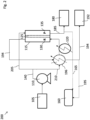
- Fig. 1 displays a diagram of an exemplary on-board fuel separation system 100 in a sweeping gas membrane distillation configuration in accordance with one or more embodiments.
- the system 100 is generally mounted within a vehicle (e.g., automobile) and operatively connected to the powertrain system of the vehicle. The operating conditions of the system 100 and the powertrain system of the vehicle are such that they ensure smooth and efficient vehicle operation.
- the system 100 includes a source fuel tank 105 for storage of the source fuel.
- the source fuel is a conventional liquid fuel such as gasoline, naphtha, or diesel.
- System 100 further comprises a pump 110 and membrane module 115, where the pump 110 is configured to send the liquid fuel from the source fuel tank 105 to the membrane module 115.
- the pump 110 can be part of the existing fuel rail in the vehicle.
- the liquid fuel can be heated via a preheater 120 before reaching the membrane module 115.
- a membrane 125 is used separate the vapor molecules of the liquid fuel from the liquid molecules of the liquid fuel based on relative volatility and diffusivity.
- the membrane 125 is a hydrophilic membrane that is generally impermeable to liquid.
- the membrane 125 can be of various forms and shapes, including in the form of a flat sheet, a hollow fiber, or a spiral wound.
- the membrane 125 of the present systems does not act as a selective barrier in that it does not separate the liquid fuel based on selective molecular size permeability or the solubility of the different components of the liquid fuel. Further, the membrane 125 does not act as a chemically selective barrier.
- the membrane 125 acts as a liquid-gas interface such that vapor molecules of the liquid fuel permeate through the membrane 125, while the liquid molecules of the fuel do not.
- the membrane 125 is "passive" in the sense that it does not actively cause the separation of the liquid fuel.
- the membrane 125 acts as a porous, physical barrier between the liquid and vapor phase of the liquid fuel.
- the liquid fuel in the membrane 125 has a temperature that is below the bubble point temperature of the liquid fuel to avoid boiling of the fuel.
- the membrane 125 is generally hydrophilic because the fuel use in the present systems is generally organic and hydrophobic. Thus, in order to prevent membrane wetting (i.e., filling of the membrane pores with liquid), the material of the membrane 125 provides high surface tension so that the liquid portion of the organic fuel cannot enter the membrane pores.
- the membrane module 115 further includes a retentate channel 130 and a permeate channel 135.
- the liquid fuel flows from the source tank 105 through feed conduit 140 and enters the membrane module 115 via the retentate channel 130.
- the low octane, high relative volatility component or fraction (vapor component) of the liquid fuel diffuse through the membrane 125 to the permeate channel 135, while the high octane, low relative volatility component or fraction (liquid component) of the liquid fuel remains and collects in the retentate channel 130.
- separation of the high and low octane components is enhanced by a sweeping gas stream (e.g., air at ambient temperature) that enters the permeate channel 135 via gas conduit 145.
- a sweeping gas stream e.g., air at ambient temperature
- the air from the air intake of the engine can be used as the sweeping gas stream.
- an additional air intake unrelated to the engine can be used to provide the sweeping gas for the system.
- inert gas can be used as the sweeping gas for facilitating separation of the components of the liquid fuel after contact with the membrane.
- the sweeping gas enhances the temperature difference and the vapor pressure difference between the permeate channel 135 and the retentate channel 130, thereby causing increased permeation of the low octane component through the membrane 125 and into the permeate channel 135.
- the low octane components that diffuse into the permeate channel 135 are then carried by the sweeping gas out of the permeate channel 135 via a conduit 150.
- the membrane module 115 can separate the source diesel fuel into components in a similar fashion as it separates gasoline fuel. For example, high relative volatility components of the diesel fuel diffuse through the membrane 125 to the permeate channel 135, while the low relative volatility components of the diesel fuel remains and collects in the retentate channel 130.
- the mixture of the sweeping gas and the low octane component (permeate) are then directed through the conduit 150 to a condenser 155.
- the liquid fuel from source tank 105 can optionally pass through the condenser 155 (prior to entry into the membrane module 115) as the permeate and sweeping gas is also passing through the condenser 155.
- the liquid fuel and the permeate-sweeping gas mixture enter the condenser via separate inlets and remain separated within the condenser 155 (e.g., in separate conduits)
- the lower temperature of the liquid fuel causes the permeate (low octane component) to condense into a liquid phase, thereby separating it from the sweeping gas
- the condensed low octane component can then be selectively directed to the engine 160 of the vehicle via conduit 165 for use as fuel or can be directed to a flash tank 170 via conduit 175. Controlling whether the low octane component is directed to the engine 160 or to a flash tank 170 can be controlled via a valve.
- the determination as to whether the low octane components are directed to the engine 160 or the flash tank 170 is controlled via a feedback control system.
- a combination of engine and system data can be used by the system to control the valve position, and thus control whether the low octane components are direct to the engine or to storage by way of the flash tank 170.
- the system in the vehicle can be programmed to run at a different conditions based on the engine response to the fuel. For example, the engine response to the fuel can be used to automatically select the best operating conditions for the engine.
- the knock detector is used to adjust engine parameters to the fuel.
- the low octane component is further separated from the sweeping gas, and the resulting, separated low octane component is then directed to a low octane fuel tank 180 via conduit 185.
- the separated sweeping gas can then be recycled back to gas conduit 145 via conduit 190 for reintroduction into the permeate channel 135.
- the high octane component (retentate) that collects in the retentate channel 130 is then selectively directed to a high octane fuel tank 192 via conduit 194 or can be directed to the engine 160 via conduit 195.
- the high octane components can comprise aromatic compounds, for example.
- a heat exchanger 196 can be operatively connected to the retentate channel 130 to keep the temperature in the channel 130 constant, thereby enhancing the separation of the high and low octane components.
- the source for the heat in the heat exchanger 196 can be, for example, a hot coolant or an exhaust gas. In the embodiment shown in Fig.
- the heat exchanger 196 can also act as another preheater for the liquid fuel before it reaches the membrane module 115 by utilizing the hot retentate thermal energy.
- the preheater 120 can then be used to further heat the liquid feed to the desired temperature before it enters the membrane module 115.
- a solvent can be added to the liquid fuel to alter the vapor pressure of the liquid fuel and thus enhance the separation of the high and low octane components.
- the solvent can be housed in a separate tank (not shown) operatively connected to the feed channel 140 such that the solvent can be mixed with the liquid fuel prior to liquid fuel reaching the membrane module 115.
- the solvent can be a partially or fully miscible solvent.
- solvents such as triethylene glycol (TEG) and heterocyclic solvents can be used with fuels that are high in oxygenates and aromatics to enhance separation of the fuel components, as TEG and heterocyclic solvents tend to interact strongly with oxygenates and aromatics.
- the solvent's primary function is to extract certain components with certain functional groups from the liquid fuel or to alter the partial vapor pressure of the fuel to enhance separation of the fuel components. Whether components are extracted or whether partial vapor pressure is altered depends upon the solvent used, the amount of solvent used, and the composition of the liquid fuel. Depending on the solvent used, the solvent can extract either high octane or low octane components (or, for diesel fuels, low cetane or high cetane components). In embodiments in which a solvent is used, the solvent collects with the high octane component in the retentate channel 130.
- the high octane component can be subsequently directed to a flash tank (not shown) to undergo flash distillation to separate the high octane component from the solvent prior to high octane component being delivered to the high octane fuel tank 192 or the engine 160.
- Fig. 2 displays a diagram of an exemplary on-board fuel separation system 200 in accordance with one or more embodiments.
- the system 200 is similar to the system 100 of exemplified in Fig. 1 , except in system 200, separation of the fuel components is accomplished via direct contact membrane distillation rather than a sweeping gas membrane distillation.
- System 200 as exemplified at Fig. 2 , can comprise several of the same components as are included in system 100, such as a source fuel tank 105, a pump 110, a membrane module 115 (including membrane 125, retentate channel 130 and permeate channel 135), a preheater 120, a low octane fuel tank 180, and a high octane fuel tank 192.
- liquid fuel from the source tank 105 is pumped (via pum110) to both the permeate channel 135 and the retentate channel 130.
- the liquid fuel is delivered via pump 110 to the feed channel 140.
- the feed channel 140 is then split into a permeate feed channel 205 and a retentate feed channel 210, where the permeate feed channel 205 delivers a portion of the liquid fuel to the permeate channel 135, and the retentate feed channel 210 delivers a portion of the liquid fuel to the retentate channel 130.
- both the permeate channel 135 and the retentate channel 130 begin with the fuel having the same octane.
- the portion of the liquid fuel delivered to the retentate channel 130 can be first delivered to a heat exchanger 196 for heating of the fuel prior to its delivery to the retentate channel 130.
- the retentate channel 130 is thus maintained at a higher temperature than the permeate channel 135 due to preheating of the liquid fuel delivered retentate channel.
- This temperature difference between the retentate channel 130 and the permeate channel 135 creates a vapor pressure difference between the channels, thereby resulting in low octane components in the retentate channel 130 permeating through the hydrophilic membrane 125 to the permeate channel 135, where the permeating components contact the colder liquid fuel.
- octane value for the fuel component in the permeate channel 135 decreases, while the octane value for the fuel component in the retentate channel 130 increases.
- the permeate (predominately low octane components) are selectively delivered from the permeate channel 135 to the low octane fuel tank 180 via conduit 185 or delivered to the engine 160 via conduit 165.
- the retentate (predominately high octane components) are delivered from the retentate channel 130 to the high octane fuel tank 192 via conduit 194 or can be selectively directed to the engine 160 via conduit 195.
- the retentate can pass through the heat exchanger 196, thereby transferring heat to the liquid fuel in the retentate feed channel 210 before it reaches the retentate channel 130. As a result, the retentate is cooled prior to being delivered to the high octane fuel tank 192 or the engine 160.
- a solvent can be added to the liquid fuel to alter the vapor pressure of the liquid fuel and thus enhance the separation of the high and low octane components.
- the solvent collects with the high octane component in the retentate channel 130.
- the high octane component can be subsequently directed to a flash tank (not shown) to undergo flash distillation to separate the high octane component from the solvent prior to high octane component being delivered to the high octane fuel tank 192 or the engine 160.
- the primary driving force of the separation of low and high octane components (fractions) via membrane distillation is chemical potential, specifically the chemical potential difference between the retentate and permeate channels.
- chemical potential difference between the channels the greater the driving force is and thus the greater the separation between the components is.
- Temperature and partial pressure difference contribute to overall chemical potential difference between the retentate and permeate channels.
- the temperature difference between the retentate channel and the permeate channel helps to create differences in partial pressure between the channels, which creates and maintains the flux of low octane components that permeates the membrane into the permeate channel.
- the temperature and partial pressure differences between the retentate and permeate channels further creates a difference between the channels in chemical potential, which is a function of temperature, pressure, and composition.
- the temperature and partial pressure differences between the retentate and permeate channels, and as a result the separation of the low and high octane components, are further enhanced in embodiments of the present systems that utilize both a sweeping gas in the permeate channel and a heat exchanger operatively connected to the retentate channel.
- the sweeping gas in the permeate channel and the heat exchanger connected to the retentate channel act in a complementary fashion to create an even greater difference in temperature and partial pressure between the two channels than in embodiments in which only one of a sweeping gas or a heat exchanger are used.
- Utilization of the present systems and methods allow octane-on-demand systems to operate more efficiently.
- the present systems can be configured such that the engine consumes the separated high octane components.
- the present systems can be configured such that the engine consumes the separated low octane components.
- the present systems and methods improve fuel efficiency for internal combustion engines.
- the present systems and methods allow high octane components to be separated from normal fuel streams, the usage of complex processes in refineries to produce high octane fuels is reduced, thereby reducing greenhouse gas emissions (e.g., COz emissions).
- the present systems also provide an advantage over current systems, such as current octane-on-demand systems, in that the present system allows a user to use the same conventional fuel used at gas stations.
- the user can fill the source fuel tank 105 with conventional fuel just as a user would fill up the tank of any other vehicle.
- a vehicle that utilizes the present system can operate more efficiently, as the system separates the conventional fuel into high and low octane components, which allows the engine to utilize high octane components during periods of high load, and low octane components during periods of low load.
- Figs. 3A-3B and Figs. 4A-4B illustrate the performance of exemplary flat plate membrane distillation systems in separating a 91 gasoline surrogate fuel into low octane and high octane fuels in accordance with one or more embodiments of the present application.
- Figs. 3A-3B shows how volumetric fraction ( Fig. 3A ) and octane rating ( Fig. 3B ) change with retentate temperature respectively in a sweeping gas membrane distillation configuration (SGMD) when the permeate channel consists of air at ambient temperature.
- SGMD sweeping gas membrane distillation configuration
- Fig. 4A-4B shows how volumetric fraction and octane rating changes with retentate temperature respectively in a direct contact membrane distillation (DCMD) configuration in accordance with one or more embodiments of the present application.
- the permeate channel consists of 91 gasoline surrogate fuel at ambient temperature.
- Fig. 4A shows that, as the retentate temperature increases in the direct contact configuration, the volumetric fraction of permeate increases since more components are able to change into gas phase and penetrate the membrane.
- octane rating separation increases since the retentate channel becomes more concentrated in the high octane components ( Fig. 4B ).
Landscapes
- Engineering & Computer Science (AREA)
- Chemical & Material Sciences (AREA)
- Oil, Petroleum & Natural Gas (AREA)
- Water Supply & Treatment (AREA)
- Combustion & Propulsion (AREA)
- Mechanical Engineering (AREA)
- General Engineering & Computer Science (AREA)
- Chemical Kinetics & Catalysis (AREA)
- General Chemical & Material Sciences (AREA)
- Organic Chemistry (AREA)
- Production Of Liquid Hydrocarbon Mixture For Refining Petroleum (AREA)
- Separation Using Semi-Permeable Membranes (AREA)
Description
- The present disclosure is directed to systems and methods for separating fuels based on relative volatility and diffusivity. In particular, the present disclosure is directed to on-board systems and methods for separating fuel in vehicles for subsequent use in an internal combustion engine.
- While newer, greener energy sources and methods for utilizing such sources continue to be explored, crude oil is still one of the primary sources of the world's energy. As such, gasoline, a derivative of crude oil, remains a primary fuel for internal combustion engines.
- In order to increase fuel efficiency and reduce carbon emissions from gasoline, new systems, such as octane-on-demand systems, are being developed in which the engine can make use of lower quality fuels. While these systems have shown promise, they still remain inefficient in their utilization of gasoline and require extensive and costly modification to existing vehicles in order to implement the system.
- Accordingly, there is a need for a solution that increases fuel efficiency for internal combustion engines, reduces carbon emissions, and yet remains cost-effective.
-
US20170368504 disclose an on-board fuel separation system includes a supply fuel tank configured to store an input fuel stream; a fuel separator fluidly coupled to the supply fuel tank and configured to separate the input fuel stream into a first fractional fuel stream and a second fractional fuel stream. The fuel separator includes a membrane that includes a plurality of pores sized based on a molecular size of one or more components of the first fractional fuel stream. The system includes a first fractional fuel tank fluidly coupled to the fuel separator to receive the first fractional fuel stream passed through the membrane and defined by a first auto-ignition characteristic value. The system includes a second fractional fuel stream coupled to the fuel separator to receive the second fractional fuel stream from the fuel separator that is defined by a second auto-ignition characteristic value that is different than the first auto-ignition characteristic value. -
US20100121559 discloses a fuel management system for using water for on-board vehicular separation of ethanol from ethanol-gasoline blends is described. Water or a water-alcohol mixture from a secondary tank is mixed with the ethanol-gasoline blend resulting in separation of the ethanol. By using on-board vehicular separation, the consumption of the externally supplied liquid from a secondary tank can be decreased to less than 1% of the gasoline consumption. This allows for long refilling periods for the externally supplied fluid. In another embodiment, a water-based fluid is directly injected into the cylinders of a spark ignition engine to eliminate knocking without causing misfire. In a further embodiment, an alcohol-based fluid is also used in those circumstances where injection of the water-based fluid may cause misfire. -
US20170145969 discloses an internal combustion engine fuel supply system includes a first fuel tank, a separator, and circuitry. The first fuel tank is to store fuel. The separator is connected to the first fuel tank to separate the fuel supplied from the first fuel tank into a high octane fuel and a low octane fuel which are to be supplied to an internal combustion engine. The high octane fuel has a first octane number. The low octane fuel has a second octane number lower than the first octane number. The circuitry is configured to determine whether fuel has been supplied to the first fuel tank, and to operate the separator to separate the fuel into the high octane fuel and the low octane fuel when it is determined that fuel has been supplied to the first fuel tank. -
US20090247805 discloses a method for isomerising typically paraffinic hydrocarbon fractions having 5-7 carbon atoms consisting in using a membrane separation unit which is supplied by an overhead flux from a deisohexaniser which makes it possible to maximise the isopentane quantity in isomerate. Said invention makes it possible to definitely improve the isomerate RON and MON indices by the inventive method. -
US20080128350 discloses a water separation unit includes a water separation portion. The water separation portion includes a component separation wall, a liquid chamber, and a gas chamber. The separation wall divides the water separation portion between the liquid chamber and the gas chamber. Liquid fuel is led to the liquid chamber. The separation wall includes a separation membrane, which water selectively permeates to be separated from liquid fuel in the liquid chamber. Water passing through the separation wall is temporarily stored in the gas chamber. A fuel supply apparatus supplies liquid fuel in a fuel tank to an internal-combustion engine. The apparatus includes the water separation unit. The water separation portion is disposed integrally in one of the fuel tank and a passage leading from a filler opening into the fuel tank, such that the liquid chamber is located above the gas chamber in a vertical direction of the water separation portion. - The present application describes systems and methods for on-board fuel separation forming the basis for the invention set forth in
claims 1, 6 and 13. According to a first aspect, a system for on-board fuel separation using membrane distillation is provided in which the system is mounted in a vehicle. The system includes a source fuel tank that comprises liquid fuel, and a pump configured to deliver the liquid fuel from the source fuel tank. In at least one aspect, the liquid fuel can be gasoline, naphtha, or diesel fuel. - The system also includes a membrane module that comprises a hydrophilic membrane, a retentate channel, and a permeate channel. The retentate and permeate channels are disposed on opposing sides of the hydrophilic membrane, and the retentate channel and permeate channel are configured to receive the liquid fuel from the source fuel tank via respective feed channels. The membrane module is also configured to separate the liquid fuel into a high octane fraction that remains in the retentate channel and a low octane fraction that diffuses through the hydrophilic membrane to the permeate channel. The hydrophilic membrane can be in the form of a flat sheet, a hollow fiber, or a spiral wound.
- The system further includes a low octane fuel tank configured to receive the low octane fraction from the permeate channel and a high octane fuel tank configured to receive the high octane fraction from the retentate channel. The system also includes an engine fluidly connected to the permeate channel and retentate channel and configured to selectively receive at least a portion of the low octane fraction and at least a portion of t he high octane fraction.
- According to another aspect, the system can further include a preheater configured to preheat the liquid fuel prior to delivery of the liquid fuel to the retentate and permeate channels of the membrane module.
- According to another aspect, the system can include a heat exchanger fluidly connected to the retentate channel and configured to maintain the temperature of the retentate channel to enhance separation of the high octane fraction from the low octane fraction in the membrane module.
- According to another aspect, only the retentate channel is configured to receive the liquid fuel from the source fuel tank via a feed channel. In accordance with this aspect, the system further includes a gas channel fluidly connected to the permeate channel and configured to deliver a sweeping gas to the permeate channel. In at least one aspect, the system can include a flash tank fluidly connected to the permeate channel and configured to selectively receive at least a portion of the low octane fraction and the sweeping gas, and to separate the low octane fraction from the sweeping gas.
- According to another aspect, the membrane module is further configured to receive a solvent for enhancing the separation of the low octane and high octane fractions, and a flash tank is further configured to separate the high octane fraction from the solvent.
- According to another aspect, a method for on-board fuel separation in a vehicle using membrane distillation is provided. In the method, the liquid fuel is pumped from the source fuel tank to the membrane module. The liquid fuel is then separated via the membrane module into a high octane fraction and a low octane fraction, where the high octane fraction collects in the retentate channel and the low octane fraction diffuses through the hydrophilic membrane to the permeate channel. At least a portion of the hot octane fraction is selectively delivered from the retentate channel to the high octane fuel tank or to the engine of the vehicle. Similarly, at least a portion of the low octane fraction is selectively delivered to the low octane fuel tank or to the engine of the vehicle.
- According to another aspect of the method, the liquid fuel is preheated prior to its delivery to the membrane module.
- According to another aspect of the method, the retentate channel is heated via a heat exchanger to enhance separation of the hot octane fraction from the low octane fraction. The heat exchanger can produce heat using a hot coolant or an exhaust gas.
- According to another aspect of the method, a sweeping gas stream is passed through the permeate channel to produce a mixture of sweeping gas and the low octane fraction, the low octane fraction is condensed in a condenser prior to delivery of the low octane fraction to the engine or the low octane fuel tank, and the low octane fraction is separated from the sweeping gas via a flash tank prior to delivery of the low octane fraction to the low octane fuel tank.
- According to another aspect of the method, a solvent is supplied to the retentate channel of the membrane module, such that the solvent enhances the separation of the low octane and high octane fractions, and the high octane fraction is then separated from the solvent via flash distillation in a flash tank.
- These and other aspects, features, and advantages can be appreciated from the accompanying description of certain embodiments of the invention and the accompanying drawing figures and claims.
-
-
Fig. 1 displays a schematic of an exemplary on-board fuel separation system that utilizes sweeping gas membrane distillation in accordance with one or more embodiments; -
Fig. 2 displays a schematic of an exemplary on-board fuel separation system that utilizes direct contact membrane distillation in accordance with one or more embodiments; -
Fig. 3A displays a graph showing how volumetric fraction changes with retentate temperature in the separation system utilizing sweeping gas membrane distillation (SGMD) in accordance with one or more embodiments; -
Fig. 3B displays a graph showing how Research Octane Number (RON) changes with retentate temperature in the separation system utilizing sweeping gas membrane distillation (SGMD) in accordance with one or more embodiments; -
Fig. 4A displays a graph showing how volumetric fraction changes with retentate temperature in the separation system utilizing direct contact membrane distillation (DCMD) in accordance with one or more embodiments; and -
Fig. 4B displays a graph showing how Research Octane Number (RON) changes with retentate temperature in the separation system utilizing direct contact membrane distillation (DCMD) in accordance with one or more embodiments. - The present application describes on-board systems and methods for separating fuel. In particular, the application describes systems and methods for on-board fuel separation using membrane distillation. The present application targets challenges associated with, among other things, gasoline fuel efficiency for internal combustion engines and carbon emissions, and provides solutions to such technical challenges.
- In one or more embodiments, the on-board system comprises a source fuel tank for housing liquid fuel (e.g., gasoline) and a pump for delivering the liquid fuel from the source fuel tank to a membrane module. The membrane module can include a membrane, a retentate channel, and a permeate channel. The membrane module is configured to separate the liquid fuel into a high octane fraction and a low octane fraction, where the high octane fraction collects in the retentate channel and the low octane fraction diffuses through the membrane to the permeate channel. The high octane and low octane fractions are then be passed to respective fuel storage tanks or to the engine for use as fuel.
- The present methods use membrane distillation (e.g., sweeping gas membrane distillation, direct contact membrane distillation) for separating the source fuel into two separate fuel components. The membrane can act as a vapor-liquid interface and a liquid barrier. The separation of the fuel can be based on relative volatility and diffusivity through the membrane pores and the driving force of separation is generally chemical potential, which relates to vapor pressure difference and temperature difference. In certain embodiments, a partially or fully miscible solvent can be added to the liquid fuel to alter the vapor pressures and thereby enhance the separation process. The present method uses less energy than conventional distillation process.
- The present systems and methods can separate fuel components based on their relative volatility, molecular diffusion in air, and/or Knudsen diffusion in pores. This allows the system to separate a source fuel into two fuels of varying octane numbers (i.e., a low octane fuel and a high octane fuel) to improve engine efficiency and fuel economy. Similarly, the present systems and methods can also be used to separate certain fuels (e.g., diesel fuels) into low cetane and high cetane fuel components, or high and low volatility components. Another advantage is that the membrane used in the present systems and methods does not need to be designed with selective permeability since it acts as a liquid-phase interface rather than a selective barrier. The separation of the fuel can be achieved by creating a partial vapor pressure difference between the two channels of the membrane module and by creating a temperature difference. In both cases, a chemical potential difference is created to drive the low octane components to the permeate channel.
- The referenced on-board systems and methods for separating fuel are now described more fully with reference to the accompanying drawings, in which one or more illustrated embodiments and/or arrangements of the systems and methods are shown. The systems and methods of the present application are not limited in any way to the illustrated embodiments and/or arrangements as the illustrated embodiments and/or arrangements. It should be understood that the systems and methods as shown in the accompanying figures are merely exemplary of the systems and methods of the present application, which can be embodied in various forms as appreciated by one skilled in the art. Therefore, it is to be understood that any structural and functional details disclosed herein are not to be interpreted as limiting the systems and methods, but rather are provided as a representative embodiment and/or arrangement for teaching one skilled in the art one or more ways to implement the systems and methods.
-
Fig. 1 displays a diagram of an exemplary on-boardfuel separation system 100 in a sweeping gas membrane distillation configuration in accordance with one or more embodiments. Thesystem 100 is generally mounted within a vehicle (e.g., automobile) and operatively connected to the powertrain system of the vehicle. The operating conditions of thesystem 100 and the powertrain system of the vehicle are such that they ensure smooth and efficient vehicle operation. Thesystem 100 includes asource fuel tank 105 for storage of the source fuel. In one or more embodiments, the source fuel is a conventional liquid fuel such as gasoline, naphtha, or diesel.System 100 further comprises apump 110 andmembrane module 115, where thepump 110 is configured to send the liquid fuel from thesource fuel tank 105 to themembrane module 115. In one or more embodiments, thepump 110 can be part of the existing fuel rail in the vehicle. In at least one embodiment, the liquid fuel can be heated via apreheater 120 before reaching themembrane module 115. - In the
membrane module 115, amembrane 125 is used separate the vapor molecules of the liquid fuel from the liquid molecules of the liquid fuel based on relative volatility and diffusivity. Themembrane 125 is a hydrophilic membrane that is generally impermeable to liquid. Themembrane 125 can be of various forms and shapes, including in the form of a flat sheet, a hollow fiber, or a spiral wound. Themembrane 125 of the present systems does not act as a selective barrier in that it does not separate the liquid fuel based on selective molecular size permeability or the solubility of the different components of the liquid fuel. Further, themembrane 125 does not act as a chemically selective barrier. Rather, themembrane 125 acts as a liquid-gas interface such that vapor molecules of the liquid fuel permeate through themembrane 125, while the liquid molecules of the fuel do not. As such, themembrane 125 is "passive" in the sense that it does not actively cause the separation of the liquid fuel. Instead, themembrane 125 acts as a porous, physical barrier between the liquid and vapor phase of the liquid fuel. In one or more embodiments, the liquid fuel in themembrane 125 has a temperature that is below the bubble point temperature of the liquid fuel to avoid boiling of the fuel. - The
membrane 125 is generally hydrophilic because the fuel use in the present systems is generally organic and hydrophobic. Thus, in order to prevent membrane wetting (i.e., filling of the membrane pores with liquid), the material of themembrane 125 provides high surface tension so that the liquid portion of the organic fuel cannot enter the membrane pores. - The
membrane module 115 further includes aretentate channel 130 and apermeate channel 135. In one or more embodiments, the liquid fuel flows from thesource tank 105 throughfeed conduit 140 and enters themembrane module 115 via theretentate channel 130. Based on relative volatility and diffusivity, the low octane, high relative volatility component or fraction (vapor component) of the liquid fuel diffuse through themembrane 125 to thepermeate channel 135, while the high octane, low relative volatility component or fraction (liquid component) of the liquid fuel remains and collects in theretentate channel 130. - In the embodiment shown in
Fig. 1 , separation of the high and low octane components is enhanced by a sweeping gas stream (e.g., air at ambient temperature) that enters thepermeate channel 135 viagas conduit 145. In one or more embodiments, the air from the air intake of the engine can be used as the sweeping gas stream. In other embodiments, an additional air intake unrelated to the engine can be used to provide the sweeping gas for the system. In at least one embodiment, inert gas can be used as the sweeping gas for facilitating separation of the components of the liquid fuel after contact with the membrane. As it passes through thepermeate channel 135, the sweeping gas enhances the temperature difference and the vapor pressure difference between thepermeate channel 135 and theretentate channel 130, thereby causing increased permeation of the low octane component through themembrane 125 and into thepermeate channel 135. The low octane components that diffuse into thepermeate channel 135 are then carried by the sweeping gas out of thepermeate channel 135 via aconduit 150. For embodiments in which diesel fuel is the source fuel, themembrane module 115 can separate the source diesel fuel into components in a similar fashion as it separates gasoline fuel. For example, high relative volatility components of the diesel fuel diffuse through themembrane 125 to thepermeate channel 135, while the low relative volatility components of the diesel fuel remains and collects in theretentate channel 130. - The mixture of the sweeping gas and the low octane component (permeate) are then directed through the
conduit 150 to acondenser 155. At thecondenser 155, the liquid fuel fromsource tank 105 can optionally pass through the condenser 155 (prior to entry into the membrane module 115) as the permeate and sweeping gas is also passing through thecondenser 155. The liquid fuel and the permeate-sweeping gas mixture enter the condenser via separate inlets and remain separated within the condenser 155 (e.g., in separate conduits) The lower temperature of the liquid fuel causes the permeate (low octane component) to condense into a liquid phase, thereby separating it from the sweeping gas The condensed low octane component can then be selectively directed to theengine 160 of the vehicle viaconduit 165 for use as fuel or can be directed to aflash tank 170 viaconduit 175. Controlling whether the low octane component is directed to theengine 160 or to aflash tank 170 can be controlled via a valve. In one or more embodiments, the determination as to whether the low octane components are directed to theengine 160 or theflash tank 170 is controlled via a feedback control system. In at least one embodiment, a combination of engine and system data can be used by the system to control the valve position, and thus control whether the low octane components are direct to the engine or to storage by way of theflash tank 170. Additionally, in certain embodiments the system in the vehicle can be programmed to run at a different conditions based on the engine response to the fuel. For example, the engine response to the fuel can be used to automatically select the best operating conditions for the engine. There is a parallel practice now in gasoline engines, where the knock detector is used to adjust engine parameters to the fuel. In theflash tank 170, the low octane component is further separated from the sweeping gas, and the resulting, separated low octane component is then directed to a lowoctane fuel tank 180 viaconduit 185. The separated sweeping gas can then be recycled back togas conduit 145 viaconduit 190 for reintroduction into thepermeate channel 135. - The high octane component (retentate) that collects in the
retentate channel 130 is then selectively directed to a highoctane fuel tank 192 viaconduit 194 or can be directed to theengine 160 viaconduit 195. The high octane components can comprise aromatic compounds, for example. In at least one embodiment, aheat exchanger 196 can be operatively connected to theretentate channel 130 to keep the temperature in thechannel 130 constant, thereby enhancing the separation of the high and low octane components. The source for the heat in theheat exchanger 196 can be, for example, a hot coolant or an exhaust gas. In the embodiment shown inFig. 1 , theheat exchanger 196 can also act as another preheater for the liquid fuel before it reaches themembrane module 115 by utilizing the hot retentate thermal energy. Thepreheater 120 can then be used to further heat the liquid feed to the desired temperature before it enters themembrane module 115. - In at least one embodiment, a solvent can be added to the liquid fuel to alter the vapor pressure of the liquid fuel and thus enhance the separation of the high and low octane components. The solvent can be housed in a separate tank (not shown) operatively connected to the
feed channel 140 such that the solvent can be mixed with the liquid fuel prior to liquid fuel reaching themembrane module 115. The solvent can be a partially or fully miscible solvent. In certain embodiments, solvents such as triethylene glycol (TEG) and heterocyclic solvents can be used with fuels that are high in oxygenates and aromatics to enhance separation of the fuel components, as TEG and heterocyclic solvents tend to interact strongly with oxygenates and aromatics. The solvent's primary function is to extract certain components with certain functional groups from the liquid fuel or to alter the partial vapor pressure of the fuel to enhance separation of the fuel components. Whether components are extracted or whether partial vapor pressure is altered depends upon the solvent used, the amount of solvent used, and the composition of the liquid fuel. Depending on the solvent used, the solvent can extract either high octane or low octane components (or, for diesel fuels, low cetane or high cetane components). In embodiments in which a solvent is used, the solvent collects with the high octane component in theretentate channel 130. Accordingly, the high octane component can be subsequently directed to a flash tank (not shown) to undergo flash distillation to separate the high octane component from the solvent prior to high octane component being delivered to the highoctane fuel tank 192 or theengine 160. -
Fig. 2 displays a diagram of an exemplary on-boardfuel separation system 200 in accordance with one or more embodiments. Thesystem 200 is similar to thesystem 100 of exemplified inFig. 1 , except insystem 200, separation of the fuel components is accomplished via direct contact membrane distillation rather than a sweeping gas membrane distillation.System 200, as exemplified atFig. 2 , can comprise several of the same components as are included insystem 100, such as asource fuel tank 105, apump 110, a membrane module 115 (includingmembrane 125,retentate channel 130 and permeate channel 135), apreheater 120, a lowoctane fuel tank 180, and a highoctane fuel tank 192. - In the
system 200, liquid fuel from thesource tank 105 is pumped (via pum110) to both thepermeate channel 135 and theretentate channel 130. In particular, as shown inFig. 2 , the liquid fuel is delivered viapump 110 to thefeed channel 140. Thefeed channel 140 is then split into apermeate feed channel 205 and aretentate feed channel 210, where thepermeate feed channel 205 delivers a portion of the liquid fuel to thepermeate channel 135, and theretentate feed channel 210 delivers a portion of the liquid fuel to theretentate channel 130. As such, both thepermeate channel 135 and theretentate channel 130 begin with the fuel having the same octane. - In one or more embodiments, the portion of the liquid fuel delivered to the
retentate channel 130 can be first delivered to aheat exchanger 196 for heating of the fuel prior to its delivery to theretentate channel 130. Theretentate channel 130 is thus maintained at a higher temperature than thepermeate channel 135 due to preheating of the liquid fuel delivered retentate channel. This temperature difference between theretentate channel 130 and thepermeate channel 135 creates a vapor pressure difference between the channels, thereby resulting in low octane components in theretentate channel 130 permeating through thehydrophilic membrane 125 to thepermeate channel 135, where the permeating components contact the colder liquid fuel. As such, as the low octane components permeate into thepermeate channel 135, octane value for the fuel component in thepermeate channel 135 decreases, while the octane value for the fuel component in theretentate channel 130 increases. - After separation of the low and high octane components in the membrane module, the permeate (predominately low octane components) are selectively delivered from the
permeate channel 135 to the lowoctane fuel tank 180 viaconduit 185 or delivered to theengine 160 viaconduit 165. Similarly, the retentate (predominately high octane components) are delivered from theretentate channel 130 to the highoctane fuel tank 192 viaconduit 194 or can be selectively directed to theengine 160 viaconduit 195. In at least one embodiment, the retentate can pass through theheat exchanger 196, thereby transferring heat to the liquid fuel in theretentate feed channel 210 before it reaches theretentate channel 130. As a result, the retentate is cooled prior to being delivered to the highoctane fuel tank 192 or theengine 160. - Like
system 100, in at least one embodiment ofsystem 200, a solvent can be added to the liquid fuel to alter the vapor pressure of the liquid fuel and thus enhance the separation of the high and low octane components. In embodiments in which a solvent is used, the solvent collects with the high octane component in theretentate channel 130. Accordingly, in this embodiment, the high octane component can be subsequently directed to a flash tank (not shown) to undergo flash distillation to separate the high octane component from the solvent prior to high octane component being delivered to the highoctane fuel tank 192 or theengine 160. - In the embodiments exemplified in system 100 (sweeping gas membrane distillation) and system 200 (direct contact membrane distillation), the primary driving force of the separation of low and high octane components (fractions) via membrane distillation is chemical potential, specifically the chemical potential difference between the retentate and permeate channels. The greater the chemical potential difference between the channels, the greater the driving force is and thus the greater the separation between the components is. Temperature and partial pressure difference contribute to overall chemical potential difference between the retentate and permeate channels. In particular, the temperature difference between the retentate channel and the permeate channel helps to create differences in partial pressure between the channels, which creates and maintains the flux of low octane components that permeates the membrane into the permeate channel. The temperature and partial pressure differences between the retentate and permeate channels further creates a difference between the channels in chemical potential, which is a function of temperature, pressure, and composition. The temperature and partial pressure differences between the retentate and permeate channels, and as a result the separation of the low and high octane components, are further enhanced in embodiments of the present systems that utilize both a sweeping gas in the permeate channel and a heat exchanger operatively connected to the retentate channel. The sweeping gas in the permeate channel and the heat exchanger connected to the retentate channel act in a complementary fashion to create an even greater difference in temperature and partial pressure between the two channels than in embodiments in which only one of a sweeping gas or a heat exchanger are used.
- Utilization of the present systems and methods allow octane-on-demand systems to operate more efficiently. In particular, at high load and high engine speed conditions, the present systems can be configured such that the engine consumes the separated high octane components. Conversely, at low load and low engine speed conditions, the present systems can be configured such that the engine consumes the separated low octane components. As such, the present systems and methods improve fuel efficiency for internal combustion engines. Moreover, because the present systems and methods allow high octane components to be separated from normal fuel streams, the usage of complex processes in refineries to produce high octane fuels is reduced, thereby reducing greenhouse gas emissions (e.g., COz emissions).
- The present systems also provide an advantage over current systems, such as current octane-on-demand systems, in that the present system allows a user to use the same conventional fuel used at gas stations. In other words, the user can fill the
source fuel tank 105 with conventional fuel just as a user would fill up the tank of any other vehicle. However, a vehicle that utilizes the present system can operate more efficiently, as the system separates the conventional fuel into high and low octane components, which allows the engine to utilize high octane components during periods of high load, and low octane components during periods of low load. -
Figs. 3A-3B andFigs. 4A-4B illustrate the performance of exemplary flat plate membrane distillation systems in separating a 91 gasoline surrogate fuel into low octane and high octane fuels in accordance with one or more embodiments of the present application. - More specifically,
Figs. 3A-3B shows how volumetric fraction (Fig. 3A ) and octane rating (Fig. 3B ) change with retentate temperature respectively in a sweeping gas membrane distillation configuration (SGMD) when the permeate channel consists of air at ambient temperature. As shown inFig. 3A , as the retentate temperature increases, the volumetric fraction of permeate increases since more components are able to change into gas phase and penetrate the membrane. Similarly, as displayed in the graph ofFig. 3B , as the retentate temperature increases, octane rating separation increases since the retentate channel becomes more concentrated in the high octane components. - Similarly,
Fig. 4A-4B shows how volumetric fraction and octane rating changes with retentate temperature respectively in a direct contact membrane distillation (DCMD) configuration in accordance with one or more embodiments of the present application. In these examples, the permeate channel consists of 91 gasoline surrogate fuel at ambient temperature. Like the sweeping gas configuration,Fig. 4A shows that, as the retentate temperature increases in the direct contact configuration, the volumetric fraction of permeate increases since more components are able to change into gas phase and penetrate the membrane. Also, as the retentate temperature increases, octane rating separation increases since the retentate channel becomes more concentrated in the high octane components (Fig. 4B ). - It should be understood that although much of the foregoing description has been directed to systems and methods for on-board separation of fuel, the system and methods disclosed herein can be similarly deployed and/or implemented in scenarios, situations, and settings far beyond the referenced scenarios. It should be further understood that any such implementation and/or deployment is within the scope of the system and methods described herein.
- It is to be further understood that like numerals in the drawings represent like elements through the several figures, and that not all components and/or steps described and illustrated with reference to the figures are required for all embodiments or arrangements. Further, the terminology used herein is for the purpose of describing particular embodiments only and is not intended to be limiting of the invention. As used herein, the singular forms "a", "an" and "the" are intended to include the plural forms as well, unless the context clearly indicates otherwise. It will be further understood that the terms ""including," "comprising," or "having," "containing," "involving," and variations thereof herein, when used in this specification, specify the presence of stated features, integers, steps, operations, elements, and/or components, but do not preclude the presence or addition of one or more other features, integers, steps, operations, elements, components, and/or groups thereof.
- It should be noted that use of ordinal terms such as "first," "second," "third," etc., in the claims to modify a claim element does not by itself connote any priority, precedence, or order of one claim element over another or the temporal order in which acts of a method are performed, but are used merely as labels to distinguish one claim element having a certain name from another element having a same name (but for use of the ordinal term) to distinguish the claim elements.
- The subject matter described above is provided by way of illustration only and should not be construed as limiting. Various modifications and changes can be made to the subject matter described herein without following the example embodiments and applications illustrated and described, and without departing from the scope of the present invention, which is set forth in the following claims.
Claims (19)
- A system for on-board fuel separation using membrane distillation, the system being mounted in a vehicle, comprising:- a source fuel tank (105) comprising liquid fuel;- a pump (110) configured to deliver the liquid fuel from the source fuel tank (105);- a membrane module (115) comprising a hydrophilic membrane (125), a retentate channel (130), and a permeate channel (135), the retentate and permeate channels being disposed on opposing sides of the hydrophilic membrane (125), wherein the retentate channel (130) and the permeate channel (135) are configured to receive the liquid fuel from the source fuel tank (105) via a feed channel (140, 205, 210), and wherein the membrane module (115) is configured to separate the liquid fuel via membrane distillation in which temperature and partial pressure differences between the retentate and permeate channels create a chemical potential difference between the retentate channel (130) and permeate channel (135) such that a high octane fraction remains in the retentate channel (130) and a low octane fraction diffuses through the hydrophilic membrane (125) to the permeate channel (135);- a low octane fuel tank (180) configured to receive the low octane fraction from the permeate channel (135);- a high octane fuel tank (192) configured to receive the high octane fraction from the retentate channel (130); and- an engine (160) fluidly connected to the permeate channel (135) and the retentate channel (130), and configured to selectively receive at least a portion of the low octane fraction and at least a portion of the high octane fraction.
- The system of claim 1, further comprising:
a preheater (120) configured to preheat the liquid fuel prior to delivery of the liquid fuel to the retentate (130) and permeate (135) channels of the membrane module (115). - The system of claim 1, wherein the hydrophilic membrane (125) is in the form of a flat sheet, a hollow fiber, or a spiral wound.
- The system of claim 1, further comprising:
a heat exchanger (196) fluidly connected to the retentate channel (130) and configured to maintain the temperature of the retentate channel (130) to enhance separation of the high octane fraction from the low octane fraction in the membrane module (115). - The system of claim 1, wherein the liquid fuel is gasoline, naphtha, or diesel fuel.
- A system for on-board fuel separation using membrane distillation, the system being mounted in a vehicle and comprising:- a source fuel tank (105) comprising liquid fuel;- a pump (110) configured to deliver the liquid fuel from the source fuel tank (105);- a membrane module (115) comprising a hydrophilic membrane (125), a retentate channel (130), and a permeate channel (135), the retentate and permeate channels being disposed on opposing sides of the hydrophilic membrane (125), wherein the retentate channel (130) is configured to receive the liquid fuel from the source fuel tank (105) via a feed channel (140), and wherein the membrane module (115) is configured to separate the liquid fuel via membrane distillation in which temperature and partial pressure differences between the retentate and permeate channels create a chemical potential difference between the retentate channel (130) and permeate channel (135) such that a high octane fraction remains in the retentate channel (130) and a low octane fraction diffuses through the hydrophilic membrane (125) to the permeate channel (135);- a gas channel (145) fluidly connected to the permeate channel (135) and configured to deliver a sweeping gas to the permeate channel (135);- a flash tank (170) fluidly connected to the permeate channel (135) and configured to selectively receive at least a portion of the low octane fraction and the sweeping gas, and to separate the low octane fraction from the sweeping gas;- a low octane fuel tank (180) configured to receive the separated low octane fraction from flash tank (170);- a high octane fuel tank (192) configured to receive the high octane fraction from the retentate channel (130); and- an engine (160) fluidly connected to the permeate channel (135) and configured to selectively receive at least a portion of the low octane fraction and at least a portion of the high octane fraction.
- The system of claim 6, further comprising:
a preheater (120) configured to preheat the liquid fuel prior to delivery of the liquid fuel to the retentate channel (130) of the membrane module (115). - The system of claim 6, further comprising:
a condenser (155) fluidly connected to the permeate channel (135) and the feed channel (140), and configured to condense the low octane fraction prior to delivery of the low octane fraction to the engine (160) or the low octane fuel tank (180). - The system of claim 6, wherein the hydrophilic membrane (125) is in the form of a flat sheet, a hollow fiber, or a spiral wound.
- The system of claim 6, further comprising:
a heat exchanger (196) fluidly connected to the retentate channel (130) and configured to maintain the temperature of the retentate channel (130) to enhance separation of the high octane fraction from the low octane fraction in the membrane module (115). - The system of claim 6, wherein the liquid fuel is gasoline, naphtha, or diesel fuel.
- The system of claim 6, wherein the feed channel (140) is further configured to receive a solvent for enhancing the separation of the low octane and high octane fractions, and wherein a second flash tank is further configured to separate the high octane fraction from the solvent.
- A method for on-board fuel separation in a vehicle using membrane distillation, the method comprising:- pumping liquid fuel from a source fuel tank (105) to a membrane module (115), wherein the membrane module (115) comprises a hydrophilic membrane (125), a retentate channel (130), and a permeate channel (135), the retentate and permeate channels being disposed on opposing sides of the hydrophilic membrane (125);- supplying a solvent to the liquid fuel upstream of the membrane module (115) before pumping the liquid fuel into the membrane module;- separating, via the membrane module (115), the liquid fuel into a high octane fraction and a low octane fraction via membrane distillation in which temperature and partial pressure differences between the retentate and permeate channels create a chemical potential difference between the retentate channel (130) and permeate channel (135), wherein the high octane fraction collects in the retentate channel (130) and the low octane fraction diffuses through the hydrophilic membrane (125) to the permeate channel (135), and wherein the solvent enhances the separation of the low octane and high octane fractions in the membrane module (115);- separating the high octane fraction from the solvent via flash distillation in a flash tank;- selectively delivering at least a portion of the high octane fraction from the flash tank to a high octane fuel tank (192) or to an engine (160) of the vehicle; and- selectively delivering at least a portion of the low octane fraction from the permeate channel (135) to a low octane fuel tank (180) or to the engine (160) of the vehicle.
- The method of claim 13, further comprising:
preheating the liquid fuel prior to its delivery to the membrane module (115). - The method of claim 13, further comprising:
heating the retentate channel (130) via a heat exchanger to enhance separation of the high octane fraction from the low octane fraction. - The method of claim 15, wherein the heat exchanger (196) produces heat using a hot coolant or an exhaust gas.
- The method of claim 13, further comprising:- passing a sweeping gas stream through the permeate channel (135) to produce a mixture of sweeping gas and the low octane fraction;- condensing the low octane fraction in a condenser (155) prior to delivery of the low octane fraction to the engine (160) or the low octane fuel tank (180); and- separating the low octane fraction from the sweeping gas via another flash tank (170) prior to delivery of the low octane fraction to the low octane fuel tank (180).
- The method of claim 13, wherein the hydrophilic membrane (125) is in the form of a flat sheet, a hollow fiber, or a spiral wound.
- The method of claim 13, wherein the liquid fuel is gasoline, naphtha, or diesel fuel.
Applications Claiming Priority (2)
| Application Number | Priority Date | Filing Date | Title |
|---|---|---|---|
| US15/896,690 US10697412B2 (en) | 2018-02-14 | 2018-02-14 | Onboard fuel separation for octane-on-demand using membrane distillation |
| PCT/US2019/013130 WO2019160628A1 (en) | 2018-02-14 | 2019-01-11 | Onboard fuel separation for octane-on-demand using membrane distillation |
Publications (2)
| Publication Number | Publication Date |
|---|---|
| EP3752726A1 EP3752726A1 (en) | 2020-12-23 |
| EP3752726B1 true EP3752726B1 (en) | 2023-06-14 |
Family
ID=65352107
Family Applications (1)
| Application Number | Title | Priority Date | Filing Date |
|---|---|---|---|
| EP19704086.8A Active EP3752726B1 (en) | 2018-02-14 | 2019-01-11 | Onboard fuel separation for octane-on-demand using membrane distillation |
Country Status (8)
| Country | Link |
|---|---|
| US (1) | US10697412B2 (en) |
| EP (1) | EP3752726B1 (en) |
| JP (1) | JP2021514441A (en) |
| KR (1) | KR102685940B1 (en) |
| CN (1) | CN111742131B (en) |
| SA (1) | SA520412476B1 (en) |
| SG (1) | SG11202007602PA (en) |
| WO (1) | WO2019160628A1 (en) |
Families Citing this family (2)
| Publication number | Priority date | Publication date | Assignee | Title |
|---|---|---|---|---|
| EP4288190A4 (en) * | 2021-02-02 | 2025-07-16 | Delta S Energy Inc | Thermal diffusion membrane, devices, systems and methods |
| US11339754B1 (en) | 2021-05-07 | 2022-05-24 | Saudi Arabian Oil Company | Vehicle system with fuel separation system and method of using same |
Family Cites Families (36)
| Publication number | Priority date | Publication date | Assignee | Title |
|---|---|---|---|---|
| US2930754A (en) | 1954-07-16 | 1960-03-29 | Pan American Refining Corp | Method of separating hydrocarbons |
| US4802987A (en) * | 1984-02-24 | 1989-02-07 | Exxon Research And Engineering Company | Selective permeation of aromatic hydrocarbons through polyethylene glycol impregnated regenerated cellulose or cellulose acetate membranes |
| US5045206A (en) | 1990-12-05 | 1991-09-03 | Exxon Research & Engineering Company | Selective multi-ring aromatics extraction using a porous, non-selective partition membrane barrier |
| US6663778B1 (en) * | 1999-10-12 | 2003-12-16 | Mansour S. Bader | Process for the treatment of aqueous streams containing inorganics |
| US6711893B2 (en) * | 2001-03-27 | 2004-03-30 | Toyota Jidosha Kabushiki Kaisha | Fuel supply apparatus for an internal combustion engine |
| US6972093B2 (en) | 2003-01-30 | 2005-12-06 | Exxonmobil Research And Engineering Company | Onboard fuel separation apparatus for an automobile |
| JP4244786B2 (en) * | 2003-11-07 | 2009-03-25 | トヨタ自動車株式会社 | In-vehicle fuel separator |
| FR2862311B1 (en) * | 2003-11-14 | 2008-05-30 | Inst Francais Du Petrole | PROCESS FOR PRODUCING HIGH OCTANE INDEXES FROM A C5 / C6 CUT USING A MENBRANE SEPARATION UNIT |
| US20060037589A1 (en) | 2004-08-17 | 2006-02-23 | Ramesh Gupta | Heat pipe for heating of gasoline for on-board octane segregation |
| US7803275B2 (en) | 2006-07-14 | 2010-09-28 | Exxonmobil Research And Engineering Company | Membrane separation process using mixed vapor-liquid feed |
| JP5019028B2 (en) * | 2006-12-04 | 2012-09-05 | 株式会社デンソー | Fuel supply device for internal combustion engine |
| WO2009006307A1 (en) * | 2007-06-28 | 2009-01-08 | Trans Ionics Corporation | Benzene recovery process |
| JP2009036151A (en) * | 2007-08-03 | 2009-02-19 | Nissan Motor Co Ltd | Starter for internal combustion engine |
| US8118009B2 (en) | 2007-12-12 | 2012-02-21 | Ford Global Technologies, Llc | On-board fuel vapor separation for multi-fuel vehicle |
| US8051828B2 (en) * | 2007-12-27 | 2011-11-08 | Exxonmobil Research And Engineering Company | Multiple fuel system for internal combustion engines |
| US8141356B2 (en) | 2008-01-16 | 2012-03-27 | Ford Global Technologies, Llc | Ethanol separation using air from turbo compressor |
| US7845315B2 (en) | 2008-05-08 | 2010-12-07 | Ford Global Technologies, Llc | On-board water addition for fuel separation system |
| WO2010053857A1 (en) | 2008-11-04 | 2010-05-14 | Ethanol Boosting Systems, Llc | Water based systems for direct injection knock prevention in spark ignition engines |
| US8211300B2 (en) * | 2008-12-22 | 2012-07-03 | Exxonmobil Research And Engineering Company | Vehicle-mounted fuel separation system |
| US8747492B2 (en) * | 2010-02-02 | 2014-06-10 | Celanese International Corporation | Ethanol/fuel blends for use as motor fuels |
| US8668750B2 (en) * | 2010-02-02 | 2014-03-11 | Celanese International Corporation | Denatured fuel ethanol compositions for blending with gasoline or diesel fuel for use as motor fuels |
| US8258363B2 (en) | 2010-09-27 | 2012-09-04 | Phillips 66 Company | Separation of aromatics with pervaporation membrane |
| US8580111B2 (en) * | 2010-11-29 | 2013-11-12 | Toyota Jidosha Kabushiki Kaisha | Device for separating fuel components |
| EP2726727B1 (en) | 2011-06-30 | 2016-03-02 | Corning Incorporated | Replaceable fuel separation unit |
| US8603300B2 (en) * | 2011-09-15 | 2013-12-10 | United Technologies Corporation | Fuel fractionation using membrane distillation |
| JP5638586B2 (en) * | 2012-06-18 | 2014-12-10 | 本田技研工業株式会社 | Fuel supply device |
| JP5502153B2 (en) * | 2012-07-09 | 2014-05-28 | 本田技研工業株式会社 | Fuel supply device |
| JP2014037786A (en) * | 2012-08-13 | 2014-02-27 | Honda Motor Co Ltd | Fuel supply device |
| JP5681160B2 (en) * | 2012-11-02 | 2015-03-04 | 本田技研工業株式会社 | Fuel separator and separator state determination method |
| EP2919894B1 (en) * | 2012-11-16 | 2020-01-15 | ExxonMobil Research and Engineering Company | Improved membrane separation process using mixed vapor-liquid feed |
| US9382854B2 (en) * | 2013-08-22 | 2016-07-05 | Ford Global Technologies, Llc | Octane separation system and operating method |
| US9664147B2 (en) * | 2013-10-24 | 2017-05-30 | Ford Global Technologies, Llc | Fuel separation system for reducing parasitic losses |
| US9732018B2 (en) * | 2014-02-11 | 2017-08-15 | Saudi Arabian Oil Company | Process for production of mixed butanols and diisobutenes as fuel blending components |
| US10190554B2 (en) * | 2014-04-07 | 2019-01-29 | Honda Motor Co., Ltd. | Fuel supply device |
| JP2017096179A (en) * | 2015-11-25 | 2017-06-01 | 本田技研工業株式会社 | Fuel supply device for internal combustion engine |
| US10124294B2 (en) | 2016-06-23 | 2018-11-13 | Saudi Arabian Oil Company | On-board fuel adjustment by molecular separation |
-
2018
- 2018-02-14 US US15/896,690 patent/US10697412B2/en active Active
-
2019
- 2019-01-11 CN CN201980010478.3A patent/CN111742131B/en not_active Expired - Fee Related
- 2019-01-11 JP JP2020540604A patent/JP2021514441A/en active Pending
- 2019-01-11 WO PCT/US2019/013130 patent/WO2019160628A1/en not_active Ceased
- 2019-01-11 KR KR1020207026023A patent/KR102685940B1/en active Active
- 2019-01-11 EP EP19704086.8A patent/EP3752726B1/en active Active
- 2019-01-11 SG SG11202007602PA patent/SG11202007602PA/en unknown
-
2020
- 2020-07-21 SA SA520412476A patent/SA520412476B1/en unknown
Also Published As
| Publication number | Publication date |
|---|---|
| CN111742131A (en) | 2020-10-02 |
| JP2021514441A (en) | 2021-06-10 |
| CN111742131B (en) | 2023-11-14 |
| SG11202007602PA (en) | 2020-09-29 |
| KR20200116514A (en) | 2020-10-12 |
| SA520412476B1 (en) | 2022-02-02 |
| US20190249630A1 (en) | 2019-08-15 |
| KR102685940B1 (en) | 2024-07-16 |
| EP3752726A1 (en) | 2020-12-23 |
| WO2019160628A1 (en) | 2019-08-22 |
| US10697412B2 (en) | 2020-06-30 |
Similar Documents
| Publication | Publication Date | Title |
|---|---|---|
| EP1443202B1 (en) | An onboard fuel separation apparatus for an automobile | |
| EP1381768B1 (en) | Use and method involving a membrane for segragating and supplying fuels to a spark ignition engine | |
| EP3417166B1 (en) | Adjusting a fuel composition on-board a vehicle | |
| US7493897B2 (en) | Fuel supply apparatus and fuel supply control apparatus for internal-combustion engine | |
| US8257583B2 (en) | Vehicle mounted fuel separation apparatus | |
| US11719200B2 (en) | Separating a fuel on-board a vehicle | |
| GB2455865A (en) | I.c. engine fuel rail assembly including a fuel separation membrane | |
| EP3417165B1 (en) | Adjusting a fuel on-board a vehicle | |
| EP3752726B1 (en) | Onboard fuel separation for octane-on-demand using membrane distillation | |
| Partridge et al. | Onboard gasoline separation for improved vehicle efficiency | |
| WO2014113020A1 (en) | Fuel separation method | |
| US10124294B2 (en) | On-board fuel adjustment by molecular separation | |
| US11339754B1 (en) | Vehicle system with fuel separation system and method of using same | |
| US10900423B2 (en) | On-board separation process | |
| JP2008095666A (en) | Fuel component separation device for internal combustion engine | |
| JP2011241803A (en) | Fuel supply control apparatus of internal combustion engine |
Legal Events
| Date | Code | Title | Description |
|---|---|---|---|
| STAA | Information on the status of an ep patent application or granted ep patent |
Free format text: STATUS: UNKNOWN |
|
| STAA | Information on the status of an ep patent application or granted ep patent |
Free format text: STATUS: THE INTERNATIONAL PUBLICATION HAS BEEN MADE |
|
| PUAI | Public reference made under article 153(3) epc to a published international application that has entered the european phase |
Free format text: ORIGINAL CODE: 0009012 |
|
| STAA | Information on the status of an ep patent application or granted ep patent |
Free format text: STATUS: REQUEST FOR EXAMINATION WAS MADE |
|
| 17P | Request for examination filed |
Effective date: 20200904 |
|
| AK | Designated contracting states |
Kind code of ref document: A1 Designated state(s): AL AT BE BG CH CY CZ DE DK EE ES FI FR GB GR HR HU IE IS IT LI LT LU LV MC MK MT NL NO PL PT RO RS SE SI SK SM TR |
|
| AX | Request for extension of the european patent |
Extension state: BA ME |
|
| DAV | Request for validation of the european patent (deleted) | ||
| DAX | Request for extension of the european patent (deleted) | ||
| GRAP | Despatch of communication of intention to grant a patent |
Free format text: ORIGINAL CODE: EPIDOSNIGR1 |
|
| STAA | Information on the status of an ep patent application or granted ep patent |
Free format text: STATUS: GRANT OF PATENT IS INTENDED |
|
| INTG | Intention to grant announced |
Effective date: 20230125 |
|
| GRAS | Grant fee paid |
Free format text: ORIGINAL CODE: EPIDOSNIGR3 |
|
| GRAA | (expected) grant |
Free format text: ORIGINAL CODE: 0009210 |
|
| STAA | Information on the status of an ep patent application or granted ep patent |
Free format text: STATUS: THE PATENT HAS BEEN GRANTED |
|
| AK | Designated contracting states |
Kind code of ref document: B1 Designated state(s): AL AT BE BG CH CY CZ DE DK EE ES FI FR GB GR HR HU IE IS IT LI LT LU LV MC MK MT NL NO PL PT RO RS SE SI SK SM TR |
|
| REG | Reference to a national code |
Ref country code: CH Ref legal event code: EP |
|
| REG | Reference to a national code |
Ref country code: DE Ref legal event code: R096 Ref document number: 602019030979 Country of ref document: DE |
|
| P01 | Opt-out of the competence of the unified patent court (upc) registered |
Effective date: 20230529 |
|
| REG | Reference to a national code |
Ref country code: AT Ref legal event code: REF Ref document number: 1579401 Country of ref document: AT Kind code of ref document: T Effective date: 20230715 |
|
| REG | Reference to a national code |
Ref country code: LT Ref legal event code: MG9D |
|
| REG | Reference to a national code |
Ref country code: NL Ref legal event code: MP Effective date: 20230614 |
|
| PG25 | Lapsed in a contracting state [announced via postgrant information from national office to epo] |
Ref country code: SE Free format text: LAPSE BECAUSE OF FAILURE TO SUBMIT A TRANSLATION OF THE DESCRIPTION OR TO PAY THE FEE WITHIN THE PRESCRIBED TIME-LIMIT Effective date: 20230614 Ref country code: NO Free format text: LAPSE BECAUSE OF FAILURE TO SUBMIT A TRANSLATION OF THE DESCRIPTION OR TO PAY THE FEE WITHIN THE PRESCRIBED TIME-LIMIT Effective date: 20230914 Ref country code: ES Free format text: LAPSE BECAUSE OF FAILURE TO SUBMIT A TRANSLATION OF THE DESCRIPTION OR TO PAY THE FEE WITHIN THE PRESCRIBED TIME-LIMIT Effective date: 20230614 |
|
| REG | Reference to a national code |
Ref country code: AT Ref legal event code: MK05 Ref document number: 1579401 Country of ref document: AT Kind code of ref document: T Effective date: 20230614 |
|
| PG25 | Lapsed in a contracting state [announced via postgrant information from national office to epo] |
Ref country code: RS Free format text: LAPSE BECAUSE OF FAILURE TO SUBMIT A TRANSLATION OF THE DESCRIPTION OR TO PAY THE FEE WITHIN THE PRESCRIBED TIME-LIMIT Effective date: 20230614 Ref country code: NL Free format text: LAPSE BECAUSE OF FAILURE TO SUBMIT A TRANSLATION OF THE DESCRIPTION OR TO PAY THE FEE WITHIN THE PRESCRIBED TIME-LIMIT Effective date: 20230614 Ref country code: LV Free format text: LAPSE BECAUSE OF FAILURE TO SUBMIT A TRANSLATION OF THE DESCRIPTION OR TO PAY THE FEE WITHIN THE PRESCRIBED TIME-LIMIT Effective date: 20230614 Ref country code: LT Free format text: LAPSE BECAUSE OF FAILURE TO SUBMIT A TRANSLATION OF THE DESCRIPTION OR TO PAY THE FEE WITHIN THE PRESCRIBED TIME-LIMIT Effective date: 20230614 Ref country code: HR Free format text: LAPSE BECAUSE OF FAILURE TO SUBMIT A TRANSLATION OF THE DESCRIPTION OR TO PAY THE FEE WITHIN THE PRESCRIBED TIME-LIMIT Effective date: 20230614 Ref country code: GR Free format text: LAPSE BECAUSE OF FAILURE TO SUBMIT A TRANSLATION OF THE DESCRIPTION OR TO PAY THE FEE WITHIN THE PRESCRIBED TIME-LIMIT Effective date: 20230915 |
|
| PG25 | Lapsed in a contracting state [announced via postgrant information from national office to epo] |
Ref country code: FI Free format text: LAPSE BECAUSE OF FAILURE TO SUBMIT A TRANSLATION OF THE DESCRIPTION OR TO PAY THE FEE WITHIN THE PRESCRIBED TIME-LIMIT Effective date: 20230614 |
|
| PG25 | Lapsed in a contracting state [announced via postgrant information from national office to epo] |
Ref country code: SK Free format text: LAPSE BECAUSE OF FAILURE TO SUBMIT A TRANSLATION OF THE DESCRIPTION OR TO PAY THE FEE WITHIN THE PRESCRIBED TIME-LIMIT Effective date: 20230614 |
|
| PG25 | Lapsed in a contracting state [announced via postgrant information from national office to epo] |
Ref country code: IS Free format text: LAPSE BECAUSE OF FAILURE TO SUBMIT A TRANSLATION OF THE DESCRIPTION OR TO PAY THE FEE WITHIN THE PRESCRIBED TIME-LIMIT Effective date: 20231014 |
|
| PG25 | Lapsed in a contracting state [announced via postgrant information from national office to epo] |
Ref country code: SM Free format text: LAPSE BECAUSE OF FAILURE TO SUBMIT A TRANSLATION OF THE DESCRIPTION OR TO PAY THE FEE WITHIN THE PRESCRIBED TIME-LIMIT Effective date: 20230614 Ref country code: SK Free format text: LAPSE BECAUSE OF FAILURE TO SUBMIT A TRANSLATION OF THE DESCRIPTION OR TO PAY THE FEE WITHIN THE PRESCRIBED TIME-LIMIT Effective date: 20230614 Ref country code: RO Free format text: LAPSE BECAUSE OF FAILURE TO SUBMIT A TRANSLATION OF THE DESCRIPTION OR TO PAY THE FEE WITHIN THE PRESCRIBED TIME-LIMIT Effective date: 20230614 Ref country code: PT Free format text: LAPSE BECAUSE OF FAILURE TO SUBMIT A TRANSLATION OF THE DESCRIPTION OR TO PAY THE FEE WITHIN THE PRESCRIBED TIME-LIMIT Effective date: 20231016 Ref country code: IS Free format text: LAPSE BECAUSE OF FAILURE TO SUBMIT A TRANSLATION OF THE DESCRIPTION OR TO PAY THE FEE WITHIN THE PRESCRIBED TIME-LIMIT Effective date: 20231014 Ref country code: EE Free format text: LAPSE BECAUSE OF FAILURE TO SUBMIT A TRANSLATION OF THE DESCRIPTION OR TO PAY THE FEE WITHIN THE PRESCRIBED TIME-LIMIT Effective date: 20230614 Ref country code: CZ Free format text: LAPSE BECAUSE OF FAILURE TO SUBMIT A TRANSLATION OF THE DESCRIPTION OR TO PAY THE FEE WITHIN THE PRESCRIBED TIME-LIMIT Effective date: 20230614 Ref country code: AT Free format text: LAPSE BECAUSE OF FAILURE TO SUBMIT A TRANSLATION OF THE DESCRIPTION OR TO PAY THE FEE WITHIN THE PRESCRIBED TIME-LIMIT Effective date: 20230614 |
|
| PG25 | Lapsed in a contracting state [announced via postgrant information from national office to epo] |
Ref country code: PL Free format text: LAPSE BECAUSE OF FAILURE TO SUBMIT A TRANSLATION OF THE DESCRIPTION OR TO PAY THE FEE WITHIN THE PRESCRIBED TIME-LIMIT Effective date: 20230614 |
|
| REG | Reference to a national code |
Ref country code: DE Ref legal event code: R097 Ref document number: 602019030979 Country of ref document: DE |
|
| PLBE | No opposition filed within time limit |
Free format text: ORIGINAL CODE: 0009261 |
|
| STAA | Information on the status of an ep patent application or granted ep patent |
Free format text: STATUS: NO OPPOSITION FILED WITHIN TIME LIMIT |
|
| PG25 | Lapsed in a contracting state [announced via postgrant information from national office to epo] |
Ref country code: DK Free format text: LAPSE BECAUSE OF FAILURE TO SUBMIT A TRANSLATION OF THE DESCRIPTION OR TO PAY THE FEE WITHIN THE PRESCRIBED TIME-LIMIT Effective date: 20230614 |
|
| PG25 | Lapsed in a contracting state [announced via postgrant information from national office to epo] |
Ref country code: SI Free format text: LAPSE BECAUSE OF FAILURE TO SUBMIT A TRANSLATION OF THE DESCRIPTION OR TO PAY THE FEE WITHIN THE PRESCRIBED TIME-LIMIT Effective date: 20230614 |
|
| 26N | No opposition filed |
Effective date: 20240315 |
|
| PG25 | Lapsed in a contracting state [announced via postgrant information from national office to epo] |
Ref country code: SI Free format text: LAPSE BECAUSE OF FAILURE TO SUBMIT A TRANSLATION OF THE DESCRIPTION OR TO PAY THE FEE WITHIN THE PRESCRIBED TIME-LIMIT Effective date: 20230614 Ref country code: IT Free format text: LAPSE BECAUSE OF FAILURE TO SUBMIT A TRANSLATION OF THE DESCRIPTION OR TO PAY THE FEE WITHIN THE PRESCRIBED TIME-LIMIT Effective date: 20230614 |
|
| REG | Reference to a national code |
Ref country code: DE Ref legal event code: R119 Ref document number: 602019030979 Country of ref document: DE |
|
| PG25 | Lapsed in a contracting state [announced via postgrant information from national office to epo] |
Ref country code: MC Free format text: LAPSE BECAUSE OF FAILURE TO SUBMIT A TRANSLATION OF THE DESCRIPTION OR TO PAY THE FEE WITHIN THE PRESCRIBED TIME-LIMIT Effective date: 20230614 |
|
| PG25 | Lapsed in a contracting state [announced via postgrant information from national office to epo] |
Ref country code: MC Free format text: LAPSE BECAUSE OF FAILURE TO SUBMIT A TRANSLATION OF THE DESCRIPTION OR TO PAY THE FEE WITHIN THE PRESCRIBED TIME-LIMIT Effective date: 20230614 |
|
| REG | Reference to a national code |
Ref country code: CH Ref legal event code: PL |
|
| PG25 | Lapsed in a contracting state [announced via postgrant information from national office to epo] |
Ref country code: LU Free format text: LAPSE BECAUSE OF NON-PAYMENT OF DUE FEES Effective date: 20240111 |
|
| GBPC | Gb: european patent ceased through non-payment of renewal fee |
Effective date: 20240111 |
|
| PG25 | Lapsed in a contracting state [announced via postgrant information from national office to epo] |
Ref country code: LU Free format text: LAPSE BECAUSE OF NON-PAYMENT OF DUE FEES Effective date: 20240111 |
|
| PG25 | Lapsed in a contracting state [announced via postgrant information from national office to epo] |
Ref country code: DE Free format text: LAPSE BECAUSE OF NON-PAYMENT OF DUE FEES Effective date: 20240801 |
|
| PG25 | Lapsed in a contracting state [announced via postgrant information from national office to epo] |
Ref country code: GB Free format text: LAPSE BECAUSE OF NON-PAYMENT OF DUE FEES Effective date: 20240111 |
|
| PG25 | Lapsed in a contracting state [announced via postgrant information from national office to epo] |
Ref country code: BE Free format text: LAPSE BECAUSE OF NON-PAYMENT OF DUE FEES Effective date: 20240131 |
|
| PG25 | Lapsed in a contracting state [announced via postgrant information from national office to epo] |
Ref country code: FR Free format text: LAPSE BECAUSE OF NON-PAYMENT OF DUE FEES Effective date: 20240131 |
|
| PG25 | Lapsed in a contracting state [announced via postgrant information from national office to epo] |
Ref country code: CH Free format text: LAPSE BECAUSE OF NON-PAYMENT OF DUE FEES Effective date: 20240131 |
|
| PG25 | Lapsed in a contracting state [announced via postgrant information from national office to epo] |
Ref country code: GB Free format text: LAPSE BECAUSE OF NON-PAYMENT OF DUE FEES Effective date: 20240111 Ref country code: FR Free format text: LAPSE BECAUSE OF NON-PAYMENT OF DUE FEES Effective date: 20240131 Ref country code: DE Free format text: LAPSE BECAUSE OF NON-PAYMENT OF DUE FEES Effective date: 20240801 Ref country code: CH Free format text: LAPSE BECAUSE OF NON-PAYMENT OF DUE FEES Effective date: 20240131 Ref country code: BE Free format text: LAPSE BECAUSE OF NON-PAYMENT OF DUE FEES Effective date: 20240131 |
|
| REG | Reference to a national code |
Ref country code: BE Ref legal event code: MM Effective date: 20240131 |
|
| PG25 | Lapsed in a contracting state [announced via postgrant information from national office to epo] |
Ref country code: BG Free format text: LAPSE BECAUSE OF FAILURE TO SUBMIT A TRANSLATION OF THE DESCRIPTION OR TO PAY THE FEE WITHIN THE PRESCRIBED TIME-LIMIT Effective date: 20230614 |
|
| PG25 | Lapsed in a contracting state [announced via postgrant information from national office to epo] |
Ref country code: BG Free format text: LAPSE BECAUSE OF FAILURE TO SUBMIT A TRANSLATION OF THE DESCRIPTION OR TO PAY THE FEE WITHIN THE PRESCRIBED TIME-LIMIT Effective date: 20230614 |
|
| PG25 | Lapsed in a contracting state [announced via postgrant information from national office to epo] |
Ref country code: IE Free format text: LAPSE BECAUSE OF NON-PAYMENT OF DUE FEES Effective date: 20240111 |
|
| PG25 | Lapsed in a contracting state [announced via postgrant information from national office to epo] |
Ref country code: IE Free format text: LAPSE BECAUSE OF NON-PAYMENT OF DUE FEES Effective date: 20240111 |
|
| PG25 | Lapsed in a contracting state [announced via postgrant information from national office to epo] |
Ref country code: CY Free format text: LAPSE BECAUSE OF FAILURE TO SUBMIT A TRANSLATION OF THE DESCRIPTION OR TO PAY THE FEE WITHIN THE PRESCRIBED TIME-LIMIT; INVALID AB INITIO Effective date: 20190111 |
|
| PG25 | Lapsed in a contracting state [announced via postgrant information from national office to epo] |
Ref country code: HU Free format text: LAPSE BECAUSE OF FAILURE TO SUBMIT A TRANSLATION OF THE DESCRIPTION OR TO PAY THE FEE WITHIN THE PRESCRIBED TIME-LIMIT; INVALID AB INITIO Effective date: 20190111 |
|
| PG25 | Lapsed in a contracting state [announced via postgrant information from national office to epo] |
Ref country code: TR Free format text: LAPSE BECAUSE OF FAILURE TO SUBMIT A TRANSLATION OF THE DESCRIPTION OR TO PAY THE FEE WITHIN THE PRESCRIBED TIME-LIMIT Effective date: 20230614 |