EP3752719B1 - Support de palier de turboreacteur obtenu par fabrication additive - Google Patents
Support de palier de turboreacteur obtenu par fabrication additive Download PDFInfo
- Publication number
- EP3752719B1 EP3752719B1 EP19716971.7A EP19716971A EP3752719B1 EP 3752719 B1 EP3752719 B1 EP 3752719B1 EP 19716971 A EP19716971 A EP 19716971A EP 3752719 B1 EP3752719 B1 EP 3752719B1
- Authority
- EP
- European Patent Office
- Prior art keywords
- bearing support
- upstream
- enclosure
- sleeve
- downstream
- Prior art date
- Legal status (The legal status is an assumption and is not a legal conclusion. Google has not performed a legal analysis and makes no representation as to the accuracy of the status listed.)
- Active
Links
Images


Classifications
-
- F—MECHANICAL ENGINEERING; LIGHTING; HEATING; WEAPONS; BLASTING
- F01—MACHINES OR ENGINES IN GENERAL; ENGINE PLANTS IN GENERAL; STEAM ENGINES
- F01D—NON-POSITIVE DISPLACEMENT MACHINES OR ENGINES, e.g. STEAM TURBINES
- F01D25/00—Component parts, details, or accessories, not provided for in, or of interest apart from, other groups
- F01D25/16—Arrangement of bearings; Supporting or mounting bearings in casings
- F01D25/162—Bearing supports
- F01D25/164—Flexible supports; Vibration damping means associated with the bearing
-
- F—MECHANICAL ENGINEERING; LIGHTING; HEATING; WEAPONS; BLASTING
- F01—MACHINES OR ENGINES IN GENERAL; ENGINE PLANTS IN GENERAL; STEAM ENGINES
- F01D—NON-POSITIVE DISPLACEMENT MACHINES OR ENGINES, e.g. STEAM TURBINES
- F01D25/00—Component parts, details, or accessories, not provided for in, or of interest apart from, other groups
- F01D25/18—Lubricating arrangements
- F01D25/183—Sealing means
-
- B—PERFORMING OPERATIONS; TRANSPORTING
- B22—CASTING; POWDER METALLURGY
- B22F—WORKING METALLIC POWDER; MANUFACTURE OF ARTICLES FROM METALLIC POWDER; MAKING METALLIC POWDER; APPARATUS OR DEVICES SPECIALLY ADAPTED FOR METALLIC POWDER
- B22F10/00—Additive manufacturing of workpieces or articles from metallic powder
- B22F10/20—Direct sintering or melting
-
- B—PERFORMING OPERATIONS; TRANSPORTING
- B22—CASTING; POWDER METALLURGY
- B22F—WORKING METALLIC POWDER; MANUFACTURE OF ARTICLES FROM METALLIC POWDER; MAKING METALLIC POWDER; APPARATUS OR DEVICES SPECIALLY ADAPTED FOR METALLIC POWDER
- B22F10/00—Additive manufacturing of workpieces or articles from metallic powder
- B22F10/80—Data acquisition or data processing
-
- B—PERFORMING OPERATIONS; TRANSPORTING
- B22—CASTING; POWDER METALLURGY
- B22F—WORKING METALLIC POWDER; MANUFACTURE OF ARTICLES FROM METALLIC POWDER; MAKING METALLIC POWDER; APPARATUS OR DEVICES SPECIALLY ADAPTED FOR METALLIC POWDER
- B22F5/00—Manufacture of workpieces or articles from metallic powder characterised by the special shape of the product
- B22F5/009—Manufacture of workpieces or articles from metallic powder characterised by the special shape of the product of turbine components other than turbine blades
-
- B—PERFORMING OPERATIONS; TRANSPORTING
- B33—ADDITIVE MANUFACTURING TECHNOLOGY
- B33Y—ADDITIVE MANUFACTURING, i.e. MANUFACTURING OF THREE-DIMENSIONAL [3D] OBJECTS BY ADDITIVE DEPOSITION, ADDITIVE AGGLOMERATION OR ADDITIVE LAYERING, e.g. BY 3D PRINTING, STEREOLITHOGRAPHY OR SELECTIVE LASER SINTERING
- B33Y80/00—Products made by additive manufacturing
-
- F—MECHANICAL ENGINEERING; LIGHTING; HEATING; WEAPONS; BLASTING
- F05—INDEXING SCHEMES RELATING TO ENGINES OR PUMPS IN VARIOUS SUBCLASSES OF CLASSES F01-F04
- F05D—INDEXING SCHEME FOR ASPECTS RELATING TO NON-POSITIVE-DISPLACEMENT MACHINES OR ENGINES, GAS-TURBINES OR JET-PROPULSION PLANTS
- F05D2220/00—Application
- F05D2220/30—Application in turbines
- F05D2220/32—Application in turbines in gas turbines
- F05D2220/321—Application in turbines in gas turbines for a special turbine stage
- F05D2220/3213—Application in turbines in gas turbines for a special turbine stage an intermediate stage of the turbine
-
- F—MECHANICAL ENGINEERING; LIGHTING; HEATING; WEAPONS; BLASTING
- F05—INDEXING SCHEMES RELATING TO ENGINES OR PUMPS IN VARIOUS SUBCLASSES OF CLASSES F01-F04
- F05D—INDEXING SCHEME FOR ASPECTS RELATING TO NON-POSITIVE-DISPLACEMENT MACHINES OR ENGINES, GAS-TURBINES OR JET-PROPULSION PLANTS
- F05D2230/00—Manufacture
- F05D2230/20—Manufacture essentially without removing material
- F05D2230/22—Manufacture essentially without removing material by sintering
-
- F—MECHANICAL ENGINEERING; LIGHTING; HEATING; WEAPONS; BLASTING
- F05—INDEXING SCHEMES RELATING TO ENGINES OR PUMPS IN VARIOUS SUBCLASSES OF CLASSES F01-F04
- F05D—INDEXING SCHEME FOR ASPECTS RELATING TO NON-POSITIVE-DISPLACEMENT MACHINES OR ENGINES, GAS-TURBINES OR JET-PROPULSION PLANTS
- F05D2230/00—Manufacture
- F05D2230/20—Manufacture essentially without removing material
- F05D2230/23—Manufacture essentially without removing material by permanently joining parts together
-
- F—MECHANICAL ENGINEERING; LIGHTING; HEATING; WEAPONS; BLASTING
- F05—INDEXING SCHEMES RELATING TO ENGINES OR PUMPS IN VARIOUS SUBCLASSES OF CLASSES F01-F04
- F05D—INDEXING SCHEME FOR ASPECTS RELATING TO NON-POSITIVE-DISPLACEMENT MACHINES OR ENGINES, GAS-TURBINES OR JET-PROPULSION PLANTS
- F05D2230/00—Manufacture
- F05D2230/30—Manufacture with deposition of material
- F05D2230/31—Layer deposition
-
- F—MECHANICAL ENGINEERING; LIGHTING; HEATING; WEAPONS; BLASTING
- F05—INDEXING SCHEMES RELATING TO ENGINES OR PUMPS IN VARIOUS SUBCLASSES OF CLASSES F01-F04
- F05D—INDEXING SCHEME FOR ASPECTS RELATING TO NON-POSITIVE-DISPLACEMENT MACHINES OR ENGINES, GAS-TURBINES OR JET-PROPULSION PLANTS
- F05D2230/00—Manufacture
- F05D2230/50—Building or constructing in particular ways
- F05D2230/53—Building or constructing in particular ways by integrally manufacturing a component, e.g. by milling from a billet or one piece construction
-
- F—MECHANICAL ENGINEERING; LIGHTING; HEATING; WEAPONS; BLASTING
- F05—INDEXING SCHEMES RELATING TO ENGINES OR PUMPS IN VARIOUS SUBCLASSES OF CLASSES F01-F04
- F05D—INDEXING SCHEME FOR ASPECTS RELATING TO NON-POSITIVE-DISPLACEMENT MACHINES OR ENGINES, GAS-TURBINES OR JET-PROPULSION PLANTS
- F05D2240/00—Components
- F05D2240/50—Bearings
-
- F—MECHANICAL ENGINEERING; LIGHTING; HEATING; WEAPONS; BLASTING
- F05—INDEXING SCHEMES RELATING TO ENGINES OR PUMPS IN VARIOUS SUBCLASSES OF CLASSES F01-F04
- F05D—INDEXING SCHEME FOR ASPECTS RELATING TO NON-POSITIVE-DISPLACEMENT MACHINES OR ENGINES, GAS-TURBINES OR JET-PROPULSION PLANTS
- F05D2260/00—Function
- F05D2260/98—Lubrication
-
- Y—GENERAL TAGGING OF NEW TECHNOLOGICAL DEVELOPMENTS; GENERAL TAGGING OF CROSS-SECTIONAL TECHNOLOGIES SPANNING OVER SEVERAL SECTIONS OF THE IPC; TECHNICAL SUBJECTS COVERED BY FORMER USPC CROSS-REFERENCE ART COLLECTIONS [XRACs] AND DIGESTS
- Y02—TECHNOLOGIES OR APPLICATIONS FOR MITIGATION OR ADAPTATION AGAINST CLIMATE CHANGE
- Y02P—CLIMATE CHANGE MITIGATION TECHNOLOGIES IN THE PRODUCTION OR PROCESSING OF GOODS
- Y02P10/00—Technologies related to metal processing
- Y02P10/25—Process efficiency
-
- Y—GENERAL TAGGING OF NEW TECHNOLOGICAL DEVELOPMENTS; GENERAL TAGGING OF CROSS-SECTIONAL TECHNOLOGIES SPANNING OVER SEVERAL SECTIONS OF THE IPC; TECHNICAL SUBJECTS COVERED BY FORMER USPC CROSS-REFERENCE ART COLLECTIONS [XRACs] AND DIGESTS
- Y02—TECHNOLOGIES OR APPLICATIONS FOR MITIGATION OR ADAPTATION AGAINST CLIMATE CHANGE
- Y02T—CLIMATE CHANGE MITIGATION TECHNOLOGIES RELATED TO TRANSPORTATION
- Y02T50/00—Aeronautics or air transport
- Y02T50/60—Efficient propulsion technologies, e.g. for aircraft
Definitions
- the present invention relates to the formation of an aircraft engine bearing support by additive manufacturing.
- a turbofan engine comprises an inlet sleeve receiving the air upstream which is sucked in by a low pressure compressor, before being divided into a central primary flow and a secondary flow surrounding the primary flow. After passing the low pressure compressor, the secondary flow is propelled downstream to generate thrust by being blown around the primary flow, the upstream and downstream being defined with respect to the direction of fluid flow in the turbojet engine .
- the primary flow After passing the low pressure compressor, the primary flow passes through a high pressure compressor before reaching a combustion chamber. This primary flow is then expanded in a high pressure turbine connected in rotation with the high pressure compressor, then in a low pressure turbine connected in rotation with the low pressure compressor, before being expelled downstream.
- the high-pressure compressor and the high-pressure turbine form part of a high-pressure body which surrounds a low-pressure trunnion while rotating at a different speed from the latter, this low-pressure trunnion bearing the low pressure compressor and low pressure turbine.
- the low pressure trunnion and the high pressure body are carried upstream and downstream by bearings housed in enclosures isolating them from the rest of the engine.
- Each bearing is lubricated by oil circulating in the enclosure which surrounds it, and which is delimited by fixed elements and by the rotating element which passes through it.
- Such a bearing is carried by a support while being surrounded by the enclosure.
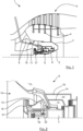
- FIG. 1 shows according to a design possibility that the invention proposes to improve, a section of a part of a turbojet engine 1 shows a low pressure journal 2, at the downstream end of which is secured a shroud 3 which extends radially to be secured to discs 4 of a low pressure turbine 5 extending around a downstream portion of journal 2.
- the journal 2 is surrounded in its downstream region by a bearing support 6 which carries a sleeve 7 intended to receive a roller bearing 8 to support the downstream part of the journal 2, and which is secured to a fixed element 9 of the motor located at its upstream, via a cone 10.
- This cone 10 widens from its downstream portion where it is secured to the support 6, towards its upstream portion where it is secured to the fixed element 9.
- the cone 10 is surrounded by a cylindrical element 11 secured to its upstream portion which it extends downstream, to delimit with this cone 10 and with the shroud 3 a portion of an enclosure 12 containing the bearing.
- a skirt 13 and two members of revolution 14 and 15 extend the central region of the cone 10 respectively upstream and downstream, this skirt and these members having external diameters of the order of the internal diameter of the cone 10.
- An upstream support 16 comprising a crown by which it is fixed upstream of the skirt 13 carries a segmented radial seal 17 which delimits an enclosure 18 upstream of the bearing 8.
- the element of revolution 14 delimits together with the pin 2 two concentric enclosures 19 and 20 located downstream of bearing 8.
- these components namely the support 6, the cone 10, the cylindrical element 11, the skirt 13, the element 14 and the upstream support 16 are fixed to each other. others according to different processes including in particular TIG welding.
- the sleeve 7 comprises a cylindrical main portion engaged in the central region of the cone 10, and this main portion is extended by a squirrel cage portion through which this sleeve 7 is rigidly secured to an upstream end of the skirt 13.
- annular space extending between the sleeve 7 and the central portion of the cone 10 is hydraulically pressurized, to radially constrain the sleeve 7 in order to ensure that it grips the outer race of the bearing which it receives when the motor is in service.
- Such an arrangement also called compression damper or " squeeze film ", is described in the patent document EP1650449 .
- the segmented radial seal 17 has its upstream face which is covered by a flange of revolution 21 with a conical internal edge making it possible to introduce a pressure drop upstream of this seal 17.
- a nozzle 22 visible on the figure 2 extends radially to introduce oil into the enclosure 18 to cool the seal 17 and lubricate the bearing 8. This oil is collected by a return path 23 visible on the picture 3 communicating the lower portions of the enclosures 18, 19 and 20, with one or more elements not shown to ensure its circulation and its cooling.
- a design such as that of figures 1 to 3 results from design and manufacturing solutions that the invention proposes to improve.
- the design and manufacture of a bearing support are complex and expensive operations involving a multiplicity of processes.
- Other bearing supports according to the prior art are known from the publications EP 3 214 273 A1 And US 2016/290164 A1 .
- the object of the invention is to provide a solution to remedy this drawback.
- the subject of the invention is a bearing support according to claim 1.
- This design and manufacturing solution makes it possible to reduce the bulk and mass of the bearing support by eliminating in particular the bolted connection elements. It also makes it possible to reduce this mass due to the fact that the fatigue resistance of the material resulting from laser fusion is greater than that of the material resulting from foundry, which makes it possible to reduce the quantity of material constituting the bearing support by reducing in particular its thickness. at different points.
- the invention also relates to a bearing support thus defined, comprising an upstream segmented radial seal support extending the upstream skirt.
- the invention also relates to a bearing support thus defined, comprising a nozzle protruding from an internal face of the upstream skirt in the upstream enclosure to cool and lubricate the upstream enclosure.
- the invention also relates to a bearing support thus defined, comprising a sleeve intended to receive an outer roller bearing race surrounding the journal, this sleeve being surrounded by the central portion, and in which the sleeve is extended by a squirrel by which it is rigidly secured to an upstream end of the upstream skirt.
- the invention also relates to a bearing support thus defined, in which the sleeve is spaced radially from the central portion which surrounds it to delimit an annular space intended to receive a hydraulic flow.
- the invention also relates to a bearing support thus defined, comprising a supply channel for the annular space surrounding the sleeve, this channel passing through the conical element.
- the invention also relates to a bearing support thus defined, comprising an oil return path connected to the upstream enclosure and/or to the downstream enclosure via a collector, this oil return path passing through the conical element.
- the invention also relates to a turbojet comprising a bearing support thus defined.
- the basic idea of the invention is to form by additive manufacturing the assembly of the bearing support including the cone with its central portion supporting the journal as well as the cylindrical element extending and surrounding this cone, with the upstream skirt and the downstream elements of revolution which delimit the enclosures surrounding the central portion.
- the invention makes it possible to integrate three functions directly into the raw part constituting the bearing support, namely a squirrel cage and a sleeve held by the latter, a segmented radial joint support, and a shock absorber. compression for the sleeve as well as other additional functions detailed below.
- the bearing support according to the invention which appears on the figure 4 , where it is identified by 26 comprises a cone 27 which widens upstream from a central portion of revolution 28 towards a non-visible portion of connection to a fixed element located at the level of the edge of largest diameter of this conical element 27.
- This support 26 has an overall shape of revolution around an axis AX corresponding to the longitudinal axis of the engine in which it is intended to be mounted, and it is oriented in such a way that the cone 27 opens or flares towards the upstream AM of the engine and tightens towards the downstream AV of the engine with respect to the direction of advance of the engine in service.
- This cone is surrounded by a cylindrical member or cylinder 29 which extends its edge of larger diameter downstream, to delimit with this cone 27 an upstream portion of a peripheral enclosure 31.
- This bearing support 26 comprises an upstream skirt 32 carried by the cone 27 to delimit an upstream enclosure 33 of the central portion 28, this skirt having a conical shape reducing from the cone 27 which carries it towards an upstream end 34 of this skirt.
- the upstream end 34 of the skirt is extended by an upstream support 36 intended to receive a segmented radial seal, not shown on the figure 4 , ensuring at the level of the enclosure 33 upstream a seal between the bearing support and the rotary trunnion, not shown.
- this upstream support 36 comprises on its internal face, downstream of the portion for receiving the segmented radial seal, wipers 37 intended to complete the sealing provided by the segmented radial seal, these wipers being in contact with an external face of revolution of the trunnion not shown.
- This bearing support 26 comprises in its downstream portion a first element of revolution 38 carried by the cone 27, in the form of a wall which surrounds the central portion 28 while narrowing downstream, delimiting a first downstream enclosure 39
- This first element of revolution carries on its internal face wipers 41 coming into contact with an outer face of the trunnion, not shown, to ensure sealing downstream of the enclosure 39.
- a second element of revolution 42 is carried by the first element of revolution 38, forming another wall of revolution which flares out downstream to delimit a second downstream enclosure 43.
- This second element of revolution bears on its internal face wipers 44 coming into contact with an outer face of the trunnion, not shown, to ensure sealing downstream of the enclosure 39.
- This support 26 comprises inside its central portion 28 a sleeve 46 intended to receive an outer ring, not shown, of a roller bearing surrounding the pin, not shown, that this support 26.
- the central portion 28 comprises an annular element 47 extending the cone 27, and the sleeve 46 extends inside the annular element 47 while being spaced radially therefrom by an annular space marked 48
- the sleeve 46 is not connected directly to the annular element 47 so as to benefit from radial mobility with respect to this annular element 47, this sleeve thus having a flexible assembly.
- a spacer ring can be provided to be engaged in the annular space 48, so as to improve its sealing and hydraulic circulation.
- the upstream end of this sleeve 46 is extended by a squirrel cage structure 49 via which the sleeve 46 is connected to the upstream end 34 of the skirt 32.
- the maintenance of the sleeve 46 is ensured only by the squirrel cage 49.
- the squirrel cage structure 49 is mainly formed of a series of columns 51 oriented parallel to the axis AX being regularly spaced from each other around this axis.
- This squirrel cage by means of which the sleeve is connected to the rest of the bearing support makes it possible to ensure a flexible maintenance of the bearing by compared to the rest of the support, the openings separating its columns give it a significantly lower rigidity than the other parts of the support which are solid.
- the bearing support 26 made in one piece also incorporates a channel 52 for supplying oil to the annular space 48, so as to form a " squeeze film " as detailed in the patent document EP1650449 .
- This channel 52 comprises a downstream portion 53 located downstream of the cone 27, of radial orientation and which is directly connected to the annular space 48, and an upstream portion 54 oriented parallel to the axis AX, which crosses the cone 27 so as to be connected to a hydraulic supply member, not shown.
- the skirt 32 carries on its internal face a nozzle 56 oriented towards the axis of revolution AX, comprising a body 57 which extends radially towards the axis AX between two columns 51 ending in a nozzle 58.
- This nozzle 58 is thus located radially in the central region of the enclosure 33, and radially between the segmented radial seal and the roller bearing. This nozzle 58 can thus diffuse oil into the enclosure 33 to cool the segmented radial seal and lubricate the roller bearing.
- the body 57 of the nozzle extends between two columns to constitute a stoppage in rotation of the cage and a rotational blocking of this cage in the event of rupture of the columns.
- the bearing support 26 formed from a single piece resulting from additive manufacturing also comprises an integrated oil return path 59 visible on the figure 6 .
- This path has the general shape of a tubular channel with an orientation substantially parallel to the axis AX.
- This path 59 extends from a collector 61 located downstream of the cone 27, and into which the upstream enclosure 33 and the first downstream enclosure 39 open, and it crosses the cone 27 to present an upstream end 62 located substantially in line with the fixing portion of the bearing support 26.
- the integration of this oil return path directly into the bearing support produces by additive manufacturing makes it possible to dispense with a drilling which had to be carried out by vibratory drilling in the state of the art.
- the use of additive manufacturing makes it possible to significantly optimize the mass of the bearing support according to the invention, because the fatigue resistance of the material produced by additive manufacturing is greater than the fatigue resistance conventional materials such as foundry, forging or machining.
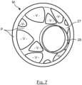
- the figure 7 shows the product of a numerical simulation determining the distribution or the topology of the material to form the bearing support in relation to the stresses and stress cycles it undergoes, without taking into account the additional functional constraints of the sealing type and others.
- the model obtained marked by M which describes a part of the bearing support 26 comprising its cone 27, fixing face, and its central portion 28, comprises solid parts P and empty parts, marked by V which correspond to scoops of ventilation not shown in the other figures.
- the finished bearing support designed for and resulting from additive manufacturing, comprises less material than the bearing support of the State of the technique consisting of an assembly of forged parts and molded, in other words allowing a significant saving in mass.
- wipers 37, 41, 44 they are formed in an abradable material different from the material forming the rest of the bearing support. These wipers can be formed with the rest of the bearing support by additive manufacturing by varying the composition of the powders deposited locally at these wipers so as to locally constitute an abradable material there.
Landscapes
- Engineering & Computer Science (AREA)
- Mechanical Engineering (AREA)
- General Engineering & Computer Science (AREA)
- Rolling Contact Bearings (AREA)
- Chemical & Material Sciences (AREA)
- Combustion & Propulsion (AREA)
- Structures Of Non-Positive Displacement Pumps (AREA)
- Supercharger (AREA)
- Sliding-Contact Bearings (AREA)
Description
- La présente invention concerne la formation d'un support de palier de moteur d'aéronef par fabrication additive.
- Un turboréacteur à double flux comporte une manche d'entrée recevant l'air en amont qui est aspiré par un compresseur basse pression, avant d'être divisé en un flux primaire central et un flux secondaire entourant le flux primaire. Après avoir passé le compresseur basse pression, le flux secondaire est propulsé vers l'aval pour générer une poussée en étant soufflé autour du flux primaire, l'amont et l'aval étant définis par rapport au sens d'écoulement de fluide dans le turboréacteur.
- Après avoir passé le compresseur basse pression, le flux primaire traverse un compresseur haute pression avant d'atteindre une chambre de combustion. Ce flux primaire est ensuite détendu dans une turbine haute pression liée en rotation avec le compresseur haute pression, puis dans une turbine basse pression liée en rotation au compresseur basse pression, avant d'être expulsé vers l'aval.
- Dans le cas d'un turboréacteur double corps, le compresseur haute pression et la turbine haute pression font partie d'un corps haute pression qui entoure un tourillon basse pression en tournant à une vitesse différente de celui-ci, ce tourillon basse pression portant le compresseur basse pression et la turbine basse pression.
- Le tourillon basse pression et le corps haute pression sont portés en amont et en aval, par des paliers logés dans des enceintes les isolant du reste du moteur. Chaque palier est lubrifié par de l'huile circulant dans l'enceinte qui l'entoure, et qui est délimitée par des éléments fixes et par l'élément rotatif qui la traverse. Un tel palier est porté par un support tout en étant entouré par l'enceinte.
- La
figure 1 montre selon une possibilité de conception que l'invention se propose d'améliorer, une section d'une partie d'un turboréacteur 1 fait apparaître un tourillon basse pression 2, à l'extrémité aval duquel est solidarisée une virole 3 qui s'étend radialement pour être solidarisée à des disques 4 d'une turbine basse pression 5 s'étendant autour d'une portion aval du tourillon 2. - Le tourillon 2 est entouré dans sa région aval par un support de palier 6 qui porte un manchon 7 destiné à recevoir un roulement à rouleaux 8 pour supporter la partie aval du tourillon 2, et qui est solidarisé à un élément fixe 9 du moteur situé à son amont, par l'intermédiaire d'un cône 10. Ce cône 10 s'évase depuis sa portion aval où il est solidarisé au support 6, vers sa portion amont où il est solidarisé à l'élément fixe 9.
- Le cône 10 est entouré par un élément cylindrique 11 solidarisé à sa portion amont qu'il prolonge vers l'aval, pour délimiter avec ce cône 10 et avec la virole 3 une portion d'une enceinte 12 renfermant le palier.
- Comme visible sur la
figure 2 , une jupe 13 et deux organes de révolution 14 et 15 prolongent la région centrale du cône 10 respectivement vers l'amont et vers l'aval, cette jupe et ces organes ayant des diamètres externes de l'ordre du diamètre interne du cône 10. Un support amont 16 comportant une couronne par laquelle il est fixé à l'amont de la jupe 13 porte un joint radial segmenté 17 qui délimite une enceinte 18 en amont du roulement 8. L'élément de révolution 14 délimite conjointement avec le tourillon 2 deux enceintes concentriques 19 et 20 situées en aval du roulement 8. - Compte tenu des contraintes de fabrication et de montage liées aux techniques connues, ces composants, à savoir le support 6, le cône 10, l'élément cylindrique 11 la jupe 13, l'élément 14 et le support amont 16 sont fixés les uns aux autres selon différents procédés incluant notamment le soudage TIG.
- Comme visible de manière plus détaillée sur la
figure 3 , le manchon 7 comporte une portion principale cylindrique engagée dans la région centrale du cône 10, et cette portion principale est prolongée par une portion en cage d'écureuil par l'intermédiaire de laquelle ce manchon 7 est rigidement solidarisé à une extrémité amont de la jupe 13. - Complémentairement, un espace annulaire s'étendant entre le manchon 7 et la portion centrale du cône 10 est pressurisé hydrauliquement, pour contraindre radialement le manchon 7 afin d'assurer qu'il serre la bague externe du roulement qu'il reçoit lorsque le moteur est en service. Un tel agencement, encore dénommé à amortisseur de compression ou « squeeze film », est décrit dans le document de brevet
EP1650449 . - Le joint radial segmenté 17 a sa face amont qui est couverte par un flasque de révolution 21 à bord interne conique permettant d'introduire une perte de charge en amont de ce joint 17.
- Complémentairement, un gicleur 22 visible sur la
figure 2 s'étend radialement pour introduire de l'huile dans l'enceinte 18 pour refroidir le joint 17 et lubrifier le roulement 8. Cette huile est collectée par un chemin de retour 23 visible sur lafigure 3 mettant en communication les portions inférieures des enceintes 18, 19 et 20, avec un ou des éléments non représentés pour assurer sa circulation et son refroidissement. - Une conception telle que celle des
figures 1 à 3 résulte de solutions de conception et de fabrication que l'invention se propose d'améliorer. D'une manière générale, la conception et la fabrication d'un support de palier sont des opérations complexes et coûteuses impliquant une multiplicité de processus. D'autres supports de palier selon l'art antérieur sont connus des publicationsEP 3 214 273 A1 etUS 2016/290164 A1 . - Le but de l'invention est d'apporter une solution pour remédier à cet inconvénient.
- A cet effet, l'invention a pour objet un support de palier selon la revendication 1.
- Cette solution de conception et de fabrication permet de réduire l'encombrement et la masse du support de palier en supprimant notamment les éléments de liaison boulonnées. Elle permet également de réduire cette masse du fait que la tenue à la fatigue du matériau issu de fusion laser est supérieure à celle du matériau issu de fonderie, ce qui permet de réduire la quantité de matière constituant le support de palier en réduisant notamment son épaisseur en différents points.
- L'invention concerne également un support de palier ainsi défini, comportant un support amont de joint radial segmenté prolongeant la jupe amont.
- L'invention concerne également un support de palier ainsi défini, comportant un gicleur dépassant d'une face interne de la jupe amont dans l'enceinte amont pour refroidir et lubrifier l'enceinte amont.
- L'invention concerne également un support de palier ainsi défini, comportant un manchon destiné à recevoir une bague externe de roulement à rouleaux entourant le tourillon, ce manchon étant entouré par la portion centrale, et dans lequel le manchon est prolongé par une cage d'écureuil par laquelle il est rigidement solidarisé à une extrémité amont de la jupe amont.
- L'invention concerne également un support de palier ainsi défini, dans lequel le manchon est espacé radialement de la portion centrale qui l'entoure pour délimiter un espace annulaire destiné à recevoir un flux hydraulique.
- L'invention concerne également un support de palier ainsi défini, comprenant un canal d'alimentation de l'espace annulaire entourant le manchon, ce canal traversant l'élément conique.
- L'invention concerne également un support de palier ainsi défini, comprenant un chemin de retour d'huile relié à l'enceinte amont et/ou à l'enceinte aval par l'intermédiaire d'un collecteur, ce chemin de retour d'huile traversant l'élément conique.
- L'invention a également pour objet un turboréacteur comportant un support de palier ainsi défini.
-
- La
figure 1 déjà décrite est une vue schématique en coupe d'une section d'une partie aval d'un turboréacteur ; - La
figure 2 déjà décrite est une vue en coupe d'une portion de section de partie aval d'un turboréacteur ; - La
figure 3 déjà décrite est une demi-vue en coupe du support palier ; - La
figure 4 est une demi-vue en coupe du support palier selon l'invention ; - La
figure 5 est une vue partielle en perspective de l'intérieur de l'enceinte amont du support de palier selon l'invention qui comporte un gicleur ; - La
figure 6 est une vue en coupe de la moitié inférieure du support de palier selon l'invention comportant un chemin de retour d'huile ; - La
figure 7 est une représentation en perspective d'une distribution de matière pour un support de palier selon l'invention. - L'idée à la base de l'invention est de former par fabrication additive l'ensemble du support de palier incluant le cône avec sa portion centrale de supportage du tourillon ainsi que l'élément cylindrique prolongeant et entourant ce cône, avec la jupe amont et les éléments de révolution aval qui délimitent les enceintes entourant la portion centrale.
- En pratique, l'invention permet d'intégrer trois fonctions directement dans la pièce brute constituant le support de palier, à savoir une cage d'écureuil et un manchon maintenu par celle-ci, un support de joint radial segmenté, et un amortisseur de compression pour le manchon ainsi que d'autres fonctions additionnelles détaillées dans la suite.
- Le support de palier selon l'invention qui apparaît sur la
figure 4 , où il est repéré par 26 comporte un cône 27 qui s'évase vers l'amont depuis une portion centrale de révolution 28 vers une portion non visible de solidarisation à un élément fixe située au niveau du bord de plus grand diamètre de cet élément conique 27. - Ce support 26 a une forme globale de révolution autour d'un axe AX correspondant à l'axe longitudinal du moteur dans lequel il est destiné à être monté, et il est orienté de telle manière que le cône 27 s'ouvre ou s'évase vers l'amont AM du moteur et se resserre vers l'aval AV du moteur par rapport au sens d'avancement du moteur en service.
- Ce cône est entouré par un organe cylindrique ou cylindre 29 qui prolonge vers l'aval son bord de plus grand diamètre, pour délimiter avec ce cône 27 une portion amont d'une enceinte périphérique 31. Ce support de palier 26 comporte une jupe amont 32 portée par le cône 27 pour délimiter une enceinte amont 33 de la portion centrale 28, cette jupe ayant une forme conique se réduisant depuis le cône 27 qui la porte vers une extrémité amont 34 de cette jupe.
- L'extrémité amont 34 de la jupe est prolongée par un support amont 36 destiné à recevoir un joint radial segmenté non représenté sur la
figure 4 , assurant au niveau de l'amont de l'enceinte 33 une étanchéité entre le support de palier et le tourillon rotatif non représenté. Complémentairement, ce support amont 36 comporte à sa face interne, en aval de la portion de réception du joint radial segmenté, des léchettes 37 destinées à compléter l'étanchéité apportée par le joint radial segmenté, ces léchettes étant au contact d'une face externe de révolution du tourillon non représenté. - Ce support de palier 26 comporte dans sa portion aval un premier élément de révolution 38 porté par le cône 27, sous forme d'une paroi qui entoure la portion centrale 28 tout en se rétrécissant vers l'aval, en délimitant une première enceinte aval 39. Ce premier élément de révolution porte à sa face interne des léchettes 41 venant au contact d'une face externe du tourillon non représenté pour assurer une étanchéité de l'aval de l'enceinte 39.
- Un second élément de révolution 42 est porté par le premier élément de révolution 38, en constituant une autre paroi de révolution qui s'évase vers l'aval pour délimiter une seconde enceinte aval 43. Ce second élément de révolution porte à sa face interne des léchettes 44 venant au contact d'une face externe du tourillon non représenté pour assurer une étanchéité de l'aval de l'enceinte 39.
- Ce support 26 comporte à l'intérieur de sa portion centrale 28 un manchon 46 destiné à recevoir une bague externe non représentée d'un roulement à rouleaux entourant le tourillon non représenté que ce support 26.
- Plus particulièrement, la portion centrale 28 comprend un élément annulaire 47 prolongeant le cône 27, et le manchon 46 s'étend à l'intérieur de l'élément annulaire 47 tout en étant espacé radialement ce celui-ci par un espace annulaire repéré par 48. Le manchon 46 n'est pas relié directement à l'élément annulaire 47 de manière à bénéficier d'une mobilité radiale par rapport à cet élément annulaire 47, ce manchon ayant ainsi un montage souple.
- Complémentairement, un anneau intercalaire non représenté peut être prévu pour être engagé dans l'espace annulaire 48, de manière à en améliorer l'étanchéité et la circulation hydraulique.
- Comme visible sur la
figure 4 , l'extrémité amont de ce manchon 46 est prolongée par une structure de cage d'écureuil 49 par l'intermédiaire de laquelle le manchon 46 est raccordé à l'extrémité amont 34 de la jupe 32. Le maintien du manchon 46 est assuré uniquement par la cage d'écureuil 49. Comme visible sur lesfigures 4 et5 , la structure de cage d'écureuil 49 est formée principalement d'une série de colonnettes 51 orientées parallèlement à l'axe AX en étant régulièrement espacées les unes des autres autour de cet axe. - Cette cage d'écureuil par l'intermédiaire de laquelle le manchon est relié au reste du support de palier permet d'assurer un maintien souple du palier par rapport au reste du support, les ajourements séparant ses colonnettes lui confèrent une rigidité significativement inférieure aux autres parties du support qui sont pleines.
- Comme visible sur la
figure 4 , le support de palier 26 fabriqué d'un seul tenant intègre également un canal 52 d'alimentation en huile de l'espace annulaire 48, de manière à former un « squeeze film » tel que détaillé dans le document de brevetEP1650449 . - Ce canal 52 comporte une portion aval 53 situé à l'aval du cône 27, d'orientation radiale et qui est directement raccordée à l'espace annulaire 48, et une portion amont 54 orientée parallèlement à l'axe AX, qui traverse le cône 27 de manière à être raccordée à un organe d'alimentation hydraulique non représenté.
- Comme il ressort de la
figure 4 , l'enceinte amont 33 est traversée par les colonnettes 51 sans que celles-ci ne la séparent en plusieurs parties. - Complémentairement, la jupe 32 porte à sa face interne un gicleur 56 orienté vers l'axe de révolution AX, comportant un corps 57 qui s'étend radialement vers l'axe AX entre deux colonnettes 51 se terminant par une buse 58. Cette buse 58 est ainsi située radialement en région centrale de l'enceinte 33, et radialement entre le joint radial segmenté et le roulement à rouleaux. Cette buse 58 peut ainsi diffuser dans l'enceinte 33 de l'huile pour refroidir le joint radial segmenté et lubrifier le roulement à rouleaux.
- Le corps 57 du gicleur s'étend entre deux colonnettes pour constituer un arrêt en rotation de la cage et de blocage en rotation de cette cage en cas de rupture de colonnettes.
- Comme visible sur la
figure 6 , le support de palier 26 formé d'une seule pièce issue de fabrication additive comporte également un chemin de retour d'huile intégré 59 visible sur lafigure 6 . Ce chemin a une forme générale de canal tubulaire d'orientation sensiblement parallèle à l'axe AX. Ce chemin 59 s'étend depuis un collecteur 61 situé en aval du cône 27, et dans lequel débouchent l'enceinte amont 33 et la première enceinte aval 39, et il traverse le cône 27 pour présenter une extrémité amont 62 située sensiblement au droit de la portion de fixation du support de palier 26. En pratique, l'intégration de ce chemin de retour d'huile à même le support de palier produit par fabrication additive permet de se dispenser d'un perçage qui devait être réalisé par perçage vibratoire dans l'Etat de la technique. - D'une manière générale, le recours à la fabrication additive permet d'optimiser significativement la masse du support de palier selon l'invention, du fait que la tenue à la fatigue du matériau produit par fabrication additive est supérieure à la tenue à la fatigue des matériaux classiques tels qu'issus de fonderie, de forgeage ou d'usinage.
- A titre d'exemple, la
figure 7 montre le produit d'une simulation numérique déterminant la distribution ou la topologie de la matière pour former le support de palier par rapport aux efforts et cycles de sollicitation qu'il subit, sans prendre en compte les contraintes fonctionnelles supplémentaires du type étanchéité et autres. - Le modèle obtenu repéré par M, qui décrit une partie du support de palier 26 comprenant son cône 27, face de fixation, et sa portion centrale 28, comporte des parties pleines P et des parties vides, repérées par V qui correspondent à des écopes de ventilation non représentées sur les autres figures.
- D'une manière plus générale, il ressort de cette modélisation M que le support de palier fini, conçu pour et issu de fabrication additive comporte moins de matière que le support de palier de l'Etat de la technique consistant en un assemblage de pièces forgées et moulées, permettant autrement dit un gain de masse significatif.
- En ce qui concerne les léchettes 37, 41, 44, elles sont formées dans un matériau abradable différent du matériau formant le reste du support de palier. Ces léchettes peuvent être formées avec le reste du support de palier par fabrication additive en faisant varier la composition des poudres déposées localement au niveau de ces léchettes de manière à y constituer localement un matériau abradable.
Claims (8)
- Support de palier (26), destiné à être solidarisé à un élément fixe de turboréacteur pour supporter un tourillon, le support de palier (26) comportant:- un élément conique (27) qui s'évase depuis une portion centrale (28) de supportage du tourillon vers une portion de solidarisation à l'élément fixe ;- une jupe amont (32) portée par l'élément conique pour délimiter une enceinte amont (33) pour la portion centrale (28) ; et- au moins un élément de révolution aval (38, 42) porté par l'élément conique (27) pour délimiter une enceinte aval (39, 43) pour la portion centrale (28) ;caractérisé en ce quele support de palier comprend un organe cylindrique (29) prolongeant la portion de solidarisation à l'élément fixe tout en entourant l'élément conique (27);et en ce que ce support de palier (26) est fabriqué en une seule pièce obtenue par fabrication additive.
- Support de palier (26) selon la revendication 1, comportant un support amont (36) de joint radial segmenté prolongeant la jupe amont (32).
- Support de palier (26) selon la revendication 1 ou 2, comportant un gicleur (56) dépassant d'une face interne de la jupe amont (32) dans l'enceinte amont (33) pour refroidir et lubrifier l'enceinte amont (33).
- Support de palier (26) selon l'une des revendications 1 à 3, comportant un manchon (46) destiné à recevoir une bague externe de roulement à rouleaux entourant le tourillon, ce manchon (46) étant entouré par la portion centrale (28), et dans lequel le manchon (46) est prolongé par une cage d'écureuil (49) par laquelle il est rigidement solidarisé à une extrémité amont (34) de la jupe amont (32).
- Support de palier (26) selon la revendication 4, dans lequel le manchon (46) est espacé radialement de la portion centrale (28) qui l'entoure pour délimiter un espace annulaire (48) destiné à recevoir un flux hydraulique.
- Support de palier (26) selon la revendication 5, comprenant un canal (52) d'alimentation de l'espace annulaire (48) entourant le manchon (46), ce canal (52) traversant l'élément conique (27).
- Support de palier (26) selon l'une des revendications précédentes, comprenant un chemin de retour d'huile (59) relié à l'enceinte amont et/ou à l'enceinte aval par l'intermédiaire d'un collecteur (61), ce chemin de retour d'huile (59) traversant l'élément conique (27).
- Turboréacteur comportant un support de palier (26) tel que défini dans l'une des revendications précédentes.
Applications Claiming Priority (2)
| Application Number | Priority Date | Filing Date | Title |
|---|---|---|---|
| FR1852557A FR3079265B1 (fr) | 2018-03-23 | 2018-03-23 | Support de palier de turboreacteur obtenu par fabrication additive |
| PCT/FR2019/050630 WO2019180375A1 (fr) | 2018-03-23 | 2019-03-20 | Support de palier de turboreacteur obtenu par fabrication additive |
Publications (2)
| Publication Number | Publication Date |
|---|---|
| EP3752719A1 EP3752719A1 (fr) | 2020-12-23 |
| EP3752719B1 true EP3752719B1 (fr) | 2023-02-15 |
Family
ID=62816714
Family Applications (1)
| Application Number | Title | Priority Date | Filing Date |
|---|---|---|---|
| EP19716971.7A Active EP3752719B1 (fr) | 2018-03-23 | 2019-03-20 | Support de palier de turboreacteur obtenu par fabrication additive |
Country Status (5)
| Country | Link |
|---|---|
| US (1) | US11585236B2 (fr) |
| EP (1) | EP3752719B1 (fr) |
| CN (1) | CN111902611B (fr) |
| FR (1) | FR3079265B1 (fr) |
| WO (1) | WO2019180375A1 (fr) |
Families Citing this family (10)
| Publication number | Priority date | Publication date | Assignee | Title |
|---|---|---|---|---|
| FR3097900B1 (fr) * | 2019-06-26 | 2021-06-04 | Safran Aircraft Engines | Support de palier de sortie de turbomachine |
| US11377977B2 (en) * | 2020-01-07 | 2022-07-05 | Raytheon Technologies Corporation | Lubrication network for an attritable engine |
| US11313248B2 (en) | 2020-05-05 | 2022-04-26 | Raytheon Technologies Corporation | 3-D lattice bearing support structure |
| DE202021104006U1 (de) | 2021-07-27 | 2021-08-04 | MTU Aero Engines AG | Lagerkäfig für ein Strahltriebwerk |
| FR3127262B1 (fr) * | 2021-09-17 | 2026-03-13 | Safran Aircraft Engines | Détecteur du contact mécanique d’une cage souple radial avec un manchon entourant cette cage dans un palier de turboréacteur |
| US12460559B2 (en) * | 2022-11-07 | 2025-11-04 | Rtx Corporation | Support structure and spring for bearing compartment |
| US20240151266A1 (en) * | 2022-11-07 | 2024-05-09 | Rtx Corporation | Thermal zone cooling in a bearing compartment |
| US12516610B2 (en) * | 2022-11-07 | 2026-01-06 | Rtx Corporation | Oil passage built into bearing compartment spring |
| US12473842B2 (en) * | 2022-11-07 | 2025-11-18 | Rtx Corporation | Annular oil distributor for bearing chamber |
| US12421872B2 (en) * | 2022-11-07 | 2025-09-23 | Rtx Corporation | Spring damping for bearing compartment |
Family Cites Families (12)
| Publication number | Priority date | Publication date | Assignee | Title |
|---|---|---|---|---|
| FR2876758B1 (fr) | 2004-10-19 | 2008-04-18 | Snecma Moteurs Sa | Dispositif de support et de guidage d'un arbre en rotation |
| US20110278801A1 (en) * | 2010-05-11 | 2011-11-17 | Morgan Construction Company | Neck seal |
| ITCO20120059A1 (it) * | 2012-12-13 | 2014-06-14 | Nuovo Pignone Srl | Metodi per produrre pale cave sagomate in 3d di turbomacchine mediante produzione additiva, pale cave di turbomacchina e turbomacchine |
| PL402185A1 (pl) * | 2012-12-21 | 2014-06-23 | General Electric Company | Połączona instalacja ściekowa do silników turbinowych |
| US20150224743A1 (en) * | 2014-02-11 | 2015-08-13 | General Electric Company | Additively manufactured article |
| DE102014208040B4 (de) * | 2014-04-29 | 2019-09-12 | MTU Aero Engines AG | Lagerkäfig und Lagereinrichtung mit einem derartigen Lagerkäfig sowie Verfahren zum Ausbilden, Reparieren und/oder Austauschen eines solchen Lagerkäfigs |
| EP3075471B1 (fr) * | 2015-03-30 | 2021-11-03 | MTU Aero Engines AG | Procédé de fabrication d'une partie de boîtier de turbine à gaz par méthode de fabrication additive |
| FR3036437B1 (fr) * | 2015-05-22 | 2017-05-05 | Snecma | Ensemble de turbomachine pour lubrifier un support de palier |
| US10113483B2 (en) * | 2016-02-23 | 2018-10-30 | General Electric Company | Sump housing for a gas turbine engine |
| FR3053728B1 (fr) * | 2016-07-07 | 2022-01-21 | Safran Aircraft Engines | Support de palier en deux pieces |
| US10436065B2 (en) * | 2016-08-18 | 2019-10-08 | United Technologies Corporation | Resilient bearing mount with integral damper fluid passage for a geared turbofan engine |
| FR3056656B1 (fr) * | 2016-09-29 | 2018-12-07 | Safran Aircraft Engines | Enceinte lubrifiee pour turbomachine d'aeronef, limitant la retention de lubrifiant lors du tangage |
-
2018
- 2018-03-23 FR FR1852557A patent/FR3079265B1/fr active Active
-
2019
- 2019-03-20 US US16/982,795 patent/US11585236B2/en active Active
- 2019-03-20 CN CN201980021404.XA patent/CN111902611B/zh active Active
- 2019-03-20 EP EP19716971.7A patent/EP3752719B1/fr active Active
- 2019-03-20 WO PCT/FR2019/050630 patent/WO2019180375A1/fr not_active Ceased
Also Published As
| Publication number | Publication date |
|---|---|
| US11585236B2 (en) | 2023-02-21 |
| EP3752719A1 (fr) | 2020-12-23 |
| FR3079265B1 (fr) | 2020-04-17 |
| WO2019180375A1 (fr) | 2019-09-26 |
| CN111902611B (zh) | 2022-11-08 |
| FR3079265A1 (fr) | 2019-09-27 |
| US20210062679A1 (en) | 2021-03-04 |
| CN111902611A (zh) | 2020-11-06 |
Similar Documents
| Publication | Publication Date | Title |
|---|---|---|
| WO2019180375A1 (fr) | Support de palier de turboreacteur obtenu par fabrication additive | |
| EP3615848B1 (fr) | Porte-satellites a cage pour un reducteur de vitesse a train epicycloïdal | |
| EP3752310B1 (fr) | Optimisation des supportages pour la fabrication additive de piece avec un evidement | |
| EP3749840B1 (fr) | Support de palier pour moteur d'aéronef fabrique par fabrication additive | |
| EP4222052B1 (fr) | Module de turbomachine equipe d'une helice et d'aubes de stator portees par deux carters et turbomachine correspondante | |
| EP3818257B1 (fr) | Dégazeur centrifuge monobloc | |
| FR2987416A1 (fr) | Dispositif de lubrification d'un reducteur epicycloidal. | |
| CA3012406A1 (fr) | Rouet de distribution d'huile avec partitionnement axial et reducteur a train epicycloidal equipe d'un tel rouet | |
| FR2987402A1 (fr) | Dispositif de lubrification d'un reducteur epicycloidal compatible d'un montage modulaire. | |
| FR3075866A1 (fr) | Tube de degazage pour une turbomachine d'aeronef a reducteur | |
| FR3014478A1 (fr) | Assemblage pour turbomachine d'aeronef comprenant un dispositif de circulation de fluide a conception amelioree vis-a-vis des risques de fuite | |
| EP3807508A1 (fr) | Porte-satellites tournant pour un reducteur mecanique d'une turbomachine | |
| EP4034755B1 (fr) | Dispositif de refroidissement par jets d'air d'un carter de turbine | |
| WO2019180364A1 (fr) | Optimisation des supports pour la fabrication additive d'une piece | |
| EP4479632B1 (fr) | Turbomachine pour un aeronef | |
| EP3990753B1 (fr) | Support de palier de sortie de turbomachine | |
| EP4102109A1 (fr) | Piece mecanique pour une turbomachine d'aeronef et turbomachine correspondante | |
| FR3052487A1 (fr) | Element tubulaire de rotor a section etoilee pour une turbomachine | |
| EP4374048B1 (fr) | Manchon rapporté sur un arbre basse pression dans une turbomachine | |
| FR3082266A1 (fr) | Dispositif de repartition d'huile pour un porte-satellites tournant d'un reducteur mecanique d'une turbomachine | |
| BE1023377B1 (fr) | Carter a bossages de compresseur de turbomachine axiale | |
| FR3118989A1 (fr) | Couronne de ventilation du support de palier arrière d'une turbomachine d'aéronef |
Legal Events
| Date | Code | Title | Description |
|---|---|---|---|
| STAA | Information on the status of an ep patent application or granted ep patent |
Free format text: STATUS: UNKNOWN |
|
| STAA | Information on the status of an ep patent application or granted ep patent |
Free format text: STATUS: THE INTERNATIONAL PUBLICATION HAS BEEN MADE |
|
| PUAI | Public reference made under article 153(3) epc to a published international application that has entered the european phase |
Free format text: ORIGINAL CODE: 0009012 |
|
| STAA | Information on the status of an ep patent application or granted ep patent |
Free format text: STATUS: REQUEST FOR EXAMINATION WAS MADE |
|
| 17P | Request for examination filed |
Effective date: 20200915 |
|
| AK | Designated contracting states |
Kind code of ref document: A1 Designated state(s): AL AT BE BG CH CY CZ DE DK EE ES FI FR GB GR HR HU IE IS IT LI LT LU LV MC MK MT NL NO PL PT RO RS SE SI SK SM TR |
|
| AX | Request for extension of the european patent |
Extension state: BA ME |
|
| DAV | Request for validation of the european patent (deleted) | ||
| DAX | Request for extension of the european patent (deleted) | ||
| GRAP | Despatch of communication of intention to grant a patent |
Free format text: ORIGINAL CODE: EPIDOSNIGR1 |
|
| STAA | Information on the status of an ep patent application or granted ep patent |
Free format text: STATUS: GRANT OF PATENT IS INTENDED |
|
| INTG | Intention to grant announced |
Effective date: 20220927 |
|
| GRAS | Grant fee paid |
Free format text: ORIGINAL CODE: EPIDOSNIGR3 |
|
| GRAA | (expected) grant |
Free format text: ORIGINAL CODE: 0009210 |
|
| STAA | Information on the status of an ep patent application or granted ep patent |
Free format text: STATUS: THE PATENT HAS BEEN GRANTED |
|
| AK | Designated contracting states |
Kind code of ref document: B1 Designated state(s): AL AT BE BG CH CY CZ DE DK EE ES FI FR GB GR HR HU IE IS IT LI LT LU LV MC MK MT NL NO PL PT RO RS SE SI SK SM TR |
|
| REG | Reference to a national code |
Ref country code: CH Ref legal event code: EP Ref country code: GB Ref legal event code: FG4D Free format text: NOT ENGLISH |
|
| REG | Reference to a national code |
Ref country code: DE Ref legal event code: R096 Ref document number: 602019025275 Country of ref document: DE |
|
| REG | Reference to a national code |
Ref country code: AT Ref legal event code: REF Ref document number: 1548324 Country of ref document: AT Kind code of ref document: T Effective date: 20230315 Ref country code: IE Ref legal event code: FG4D Free format text: LANGUAGE OF EP DOCUMENT: FRENCH |
|
| REG | Reference to a national code |
Ref country code: LT Ref legal event code: MG9D |
|
| REG | Reference to a national code |
Ref country code: NL Ref legal event code: MP Effective date: 20230215 |
|
| REG | Reference to a national code |
Ref country code: AT Ref legal event code: MK05 Ref document number: 1548324 Country of ref document: AT Kind code of ref document: T Effective date: 20230215 |
|
| PG25 | Lapsed in a contracting state [announced via postgrant information from national office to epo] |
Ref country code: RS Free format text: LAPSE BECAUSE OF FAILURE TO SUBMIT A TRANSLATION OF THE DESCRIPTION OR TO PAY THE FEE WITHIN THE PRESCRIBED TIME-LIMIT Effective date: 20230215 Ref country code: PT Free format text: LAPSE BECAUSE OF FAILURE TO SUBMIT A TRANSLATION OF THE DESCRIPTION OR TO PAY THE FEE WITHIN THE PRESCRIBED TIME-LIMIT Effective date: 20230615 Ref country code: NO Free format text: LAPSE BECAUSE OF FAILURE TO SUBMIT A TRANSLATION OF THE DESCRIPTION OR TO PAY THE FEE WITHIN THE PRESCRIBED TIME-LIMIT Effective date: 20230515 Ref country code: NL Free format text: LAPSE BECAUSE OF FAILURE TO SUBMIT A TRANSLATION OF THE DESCRIPTION OR TO PAY THE FEE WITHIN THE PRESCRIBED TIME-LIMIT Effective date: 20230215 Ref country code: LV Free format text: LAPSE BECAUSE OF FAILURE TO SUBMIT A TRANSLATION OF THE DESCRIPTION OR TO PAY THE FEE WITHIN THE PRESCRIBED TIME-LIMIT Effective date: 20230215 Ref country code: LT Free format text: LAPSE BECAUSE OF FAILURE TO SUBMIT A TRANSLATION OF THE DESCRIPTION OR TO PAY THE FEE WITHIN THE PRESCRIBED TIME-LIMIT Effective date: 20230215 Ref country code: HR Free format text: LAPSE BECAUSE OF FAILURE TO SUBMIT A TRANSLATION OF THE DESCRIPTION OR TO PAY THE FEE WITHIN THE PRESCRIBED TIME-LIMIT Effective date: 20230215 Ref country code: ES Free format text: LAPSE BECAUSE OF FAILURE TO SUBMIT A TRANSLATION OF THE DESCRIPTION OR TO PAY THE FEE WITHIN THE PRESCRIBED TIME-LIMIT Effective date: 20230215 Ref country code: AT Free format text: LAPSE BECAUSE OF FAILURE TO SUBMIT A TRANSLATION OF THE DESCRIPTION OR TO PAY THE FEE WITHIN THE PRESCRIBED TIME-LIMIT Effective date: 20230215 |
|
| PG25 | Lapsed in a contracting state [announced via postgrant information from national office to epo] |
Ref country code: SE Free format text: LAPSE BECAUSE OF FAILURE TO SUBMIT A TRANSLATION OF THE DESCRIPTION OR TO PAY THE FEE WITHIN THE PRESCRIBED TIME-LIMIT Effective date: 20230215 Ref country code: PL Free format text: LAPSE BECAUSE OF FAILURE TO SUBMIT A TRANSLATION OF THE DESCRIPTION OR TO PAY THE FEE WITHIN THE PRESCRIBED TIME-LIMIT Effective date: 20230215 Ref country code: IS Free format text: LAPSE BECAUSE OF FAILURE TO SUBMIT A TRANSLATION OF THE DESCRIPTION OR TO PAY THE FEE WITHIN THE PRESCRIBED TIME-LIMIT Effective date: 20230615 Ref country code: GR Free format text: LAPSE BECAUSE OF FAILURE TO SUBMIT A TRANSLATION OF THE DESCRIPTION OR TO PAY THE FEE WITHIN THE PRESCRIBED TIME-LIMIT Effective date: 20230516 Ref country code: FI Free format text: LAPSE BECAUSE OF FAILURE TO SUBMIT A TRANSLATION OF THE DESCRIPTION OR TO PAY THE FEE WITHIN THE PRESCRIBED TIME-LIMIT Effective date: 20230215 |
|
| PG25 | Lapsed in a contracting state [announced via postgrant information from national office to epo] |
Ref country code: SM Free format text: LAPSE BECAUSE OF FAILURE TO SUBMIT A TRANSLATION OF THE DESCRIPTION OR TO PAY THE FEE WITHIN THE PRESCRIBED TIME-LIMIT Effective date: 20230215 Ref country code: RO Free format text: LAPSE BECAUSE OF FAILURE TO SUBMIT A TRANSLATION OF THE DESCRIPTION OR TO PAY THE FEE WITHIN THE PRESCRIBED TIME-LIMIT Effective date: 20230215 Ref country code: EE Free format text: LAPSE BECAUSE OF FAILURE TO SUBMIT A TRANSLATION OF THE DESCRIPTION OR TO PAY THE FEE WITHIN THE PRESCRIBED TIME-LIMIT Effective date: 20230215 Ref country code: DK Free format text: LAPSE BECAUSE OF FAILURE TO SUBMIT A TRANSLATION OF THE DESCRIPTION OR TO PAY THE FEE WITHIN THE PRESCRIBED TIME-LIMIT Effective date: 20230215 Ref country code: CZ Free format text: LAPSE BECAUSE OF FAILURE TO SUBMIT A TRANSLATION OF THE DESCRIPTION OR TO PAY THE FEE WITHIN THE PRESCRIBED TIME-LIMIT Effective date: 20230215 |
|
| REG | Reference to a national code |
Ref country code: CH Ref legal event code: PL |
|
| REG | Reference to a national code |
Ref country code: DE Ref legal event code: R097 Ref document number: 602019025275 Country of ref document: DE |
|
| PG25 | Lapsed in a contracting state [announced via postgrant information from national office to epo] |
Ref country code: SK Free format text: LAPSE BECAUSE OF FAILURE TO SUBMIT A TRANSLATION OF THE DESCRIPTION OR TO PAY THE FEE WITHIN THE PRESCRIBED TIME-LIMIT Effective date: 20230215 |
|
| REG | Reference to a national code |
Ref country code: BE Ref legal event code: MM Effective date: 20230331 |
|
| PLBE | No opposition filed within time limit |
Free format text: ORIGINAL CODE: 0009261 |
|
| STAA | Information on the status of an ep patent application or granted ep patent |
Free format text: STATUS: NO OPPOSITION FILED WITHIN TIME LIMIT |
|
| PG25 | Lapsed in a contracting state [announced via postgrant information from national office to epo] |
Ref country code: LU Free format text: LAPSE BECAUSE OF NON-PAYMENT OF DUE FEES Effective date: 20230320 |
|
| PG25 | Lapsed in a contracting state [announced via postgrant information from national office to epo] |
Ref country code: MC Free format text: LAPSE BECAUSE OF FAILURE TO SUBMIT A TRANSLATION OF THE DESCRIPTION OR TO PAY THE FEE WITHIN THE PRESCRIBED TIME-LIMIT Effective date: 20230215 |
|
| REG | Reference to a national code |
Ref country code: IE Ref legal event code: MM4A |
|
| 26N | No opposition filed |
Effective date: 20231116 |
|
| PG25 | Lapsed in a contracting state [announced via postgrant information from national office to epo] |
Ref country code: SI Free format text: LAPSE BECAUSE OF FAILURE TO SUBMIT A TRANSLATION OF THE DESCRIPTION OR TO PAY THE FEE WITHIN THE PRESCRIBED TIME-LIMIT Effective date: 20230215 Ref country code: MC Free format text: LAPSE BECAUSE OF FAILURE TO SUBMIT A TRANSLATION OF THE DESCRIPTION OR TO PAY THE FEE WITHIN THE PRESCRIBED TIME-LIMIT Effective date: 20230215 Ref country code: LI Free format text: LAPSE BECAUSE OF NON-PAYMENT OF DUE FEES Effective date: 20230331 Ref country code: IE Free format text: LAPSE BECAUSE OF NON-PAYMENT OF DUE FEES Effective date: 20230320 Ref country code: CH Free format text: LAPSE BECAUSE OF NON-PAYMENT OF DUE FEES Effective date: 20230331 |
|
| PG25 | Lapsed in a contracting state [announced via postgrant information from national office to epo] |
Ref country code: BE Free format text: LAPSE BECAUSE OF NON-PAYMENT OF DUE FEES Effective date: 20230331 |
|
| PG25 | Lapsed in a contracting state [announced via postgrant information from national office to epo] |
Ref country code: IT Free format text: LAPSE BECAUSE OF FAILURE TO SUBMIT A TRANSLATION OF THE DESCRIPTION OR TO PAY THE FEE WITHIN THE PRESCRIBED TIME-LIMIT Effective date: 20230215 |
|
| PG25 | Lapsed in a contracting state [announced via postgrant information from national office to epo] |
Ref country code: BG Free format text: LAPSE BECAUSE OF FAILURE TO SUBMIT A TRANSLATION OF THE DESCRIPTION OR TO PAY THE FEE WITHIN THE PRESCRIBED TIME-LIMIT Effective date: 20230215 |
|
| PG25 | Lapsed in a contracting state [announced via postgrant information from national office to epo] |
Ref country code: BG Free format text: LAPSE BECAUSE OF FAILURE TO SUBMIT A TRANSLATION OF THE DESCRIPTION OR TO PAY THE FEE WITHIN THE PRESCRIBED TIME-LIMIT Effective date: 20230215 |
|
| PG25 | Lapsed in a contracting state [announced via postgrant information from national office to epo] |
Ref country code: CY Free format text: LAPSE BECAUSE OF FAILURE TO SUBMIT A TRANSLATION OF THE DESCRIPTION OR TO PAY THE FEE WITHIN THE PRESCRIBED TIME-LIMIT; INVALID AB INITIO Effective date: 20190320 |
|
| PG25 | Lapsed in a contracting state [announced via postgrant information from national office to epo] |
Ref country code: HU Free format text: LAPSE BECAUSE OF FAILURE TO SUBMIT A TRANSLATION OF THE DESCRIPTION OR TO PAY THE FEE WITHIN THE PRESCRIBED TIME-LIMIT; INVALID AB INITIO Effective date: 20190320 |
|
| PG25 | Lapsed in a contracting state [announced via postgrant information from national office to epo] |
Ref country code: TR Free format text: LAPSE BECAUSE OF FAILURE TO SUBMIT A TRANSLATION OF THE DESCRIPTION OR TO PAY THE FEE WITHIN THE PRESCRIBED TIME-LIMIT Effective date: 20230215 |
|
| PGFP | Annual fee paid to national office [announced via postgrant information from national office to epo] |
Ref country code: GB Payment date: 20260324 Year of fee payment: 8 |
|
| PGFP | Annual fee paid to national office [announced via postgrant information from national office to epo] |
Ref country code: DE Payment date: 20260320 Year of fee payment: 8 |
|
| PGFP | Annual fee paid to national office [announced via postgrant information from national office to epo] |
Ref country code: FR Payment date: 20260324 Year of fee payment: 8 |